

Feathermerchant
-
Posts
59 -
Joined
-
Last visited
Content Type
Profiles
Forums
Gallery
Events
Everything posted by Feathermerchant
-
Daniel, contact Dave Stevens at the Lumberyard. He is at Bodyplan@aol.com.
-
Guidance, Encouragement, or just a Sanity Check
Feathermerchant replied to RFP's topic in Wood ship model kits
Hi Rob, forgot to mention that John F. Leavitt published an historical paperback called "The Charles W. Morgan" through Mystic seaport. The book included ships plans for the Morgan. John was Associate Curator at Mystic seaport. Original published in 1973 and reprinted in 1998.....feathermerchant -
Guidance, Encouragement, or just a Sanity Check
Feathermerchant replied to RFP's topic in Wood ship model kits
Hi Rob, isn't it nice to have so much encouragement. I built the Morgan starting in 2000 and finished her in 2004. The kit was from Marine Model and solid hull and was bought from an Episcopalian pastor who started the original build in the 70's. The kit was of the Morgan when she was in the movie "Java". Included with the kit was a set of plans from Mystic seaport as she was in the 1895-1906 period and a contact number for Mystic Seaport. It took a bit of bashing to change her appearance. I had her on display at the Manitowoc Model Ship Show and she now is displayed in my sons accounting office conference room. I get to visit it periodically. Two things; 1, you and your lovely wife should visit the Morgan at Mystic (she is a living museum) and 2, when you have questions call them, they are the experts. It is not often that you can walk the deck of a square rigged ship that you are in the process of modeling.............feathermerchant -
Guidance, Encouragement, or just a Sanity Check
Feathermerchant replied to RFP's topic in Wood ship model kits
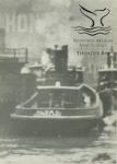
Rob, I'm 79 and building a Skipjack with my next project the scratch-build of the brig "Leon" (Underhills) followed by a scratch-build of a late 1800's tug "Alva B". That should get me into my 90's. Would also encourage you to find and join a ship modeling club. Good modeling................feathermerchant. -
Jack, nice job. Building the same vessel. Just finished the deck and installing the hatch comings. Not been following MSW for a while, but will be following your build. Interested in how you do the dredge A-frame and winders. Feathermerchant
- 250 replies
-
- 3
-

-
- willie l bennett
- model shipways
- (and 1 more)
-
Cap'n'Bob, Thanks for the picture and description. Still think the dredge will damage the hull when pulled up on deck. The roller are at the widest breath of the skipjack so the cable should be off the side of the hull, but the dredge is wide and, from what I can see, the only thing that would keep the dredge off the side of the hull would be the man tending the dredge. I checked some pictures I had from the 2010 NRG conference and the tour of St. Michael's. There was a skipjack on the rails and looking from the stern the side rail, where the dredge would come up was badly chewed up, but then the skipjack itself looked like a wreck................. feathermerchant .
-
Looking at my plans for the Bennett, I can see the rollers (a horizontal one and one at an angle at the aft end of the horizontal one) with a guard below it that the cable would run on. Still think that as the dredge came up the side of the skipjack would get beat up. Have a watercolor of a derelict skipjack showing a beat up side, but that could be just artist interpretation.
-
I am presently building the skipjack "Bennett" and enjoying reading about your progress since you are way ahead of me. One question about the dredge: Do you know if it was dropped over the side or thrown out away from the side of the skipjack? I am trying to visualize how the seaman worked putting the dredge into the water while the vessel was underway. I don't see any booms with pulleys that woud keep the dredge off the side of the vessel. Thanks.
-
Intro to Card Models Intro and Table of Contents
Feathermerchant replied to ccoyle's topic in Card and Paper Models
Chris, thanks for the tutorial on card modeling. I am in the process of building an intro presentation on card modeling for my ship modeling club. My initial model was the "Monitor" from the National Marine Sanctuary and sold through the Maritime Museum at Newport News, VA. I am now working on "Scalescenes.com" Cargo Ship and have downloaded Walden Model Co. "Imperial Russian Yacht "Livadia"". Do you have an updated list of card model vendors? In reading through part III, I noticed that neither Scale Scenes or Walden Models was on your list. Thanks again. . -
I think I have figured out how the lookout accessed the "crowsnest". I have a picture of the ship, underway, taken sometime between 1914 and 1933 when she was renamed "Banfora". The shrouds on the foremast and aft mast are rigged so that the first (forward) shroud is attached to the mast by a bolt and then each of the next three shrouds are attached to the mast in progression, one-above-the-other. Thus the shrouds and ratlines twist so that the seaman, as he climbed, would start facing thwart ship but end facing the stern. There is a second set of shrouds (2) that are attached to the lower set and continue up the mast to access the mast light. I have two conclusions: One-the seaman could not access the crowsnest from the shrouds unless he climbed up to where the shrouds are bolted to the mast, accessed the mast and then slide down the mast to the crowsnest. Don't think that happened. Second-The shrouds are to support the mast. The ratlines were added only for the seaman to access the upper part of the mast for sail handling. (Yes, she could be rigged with fore-&-aft sails (The builders plans show the sails rigged)). Here is the interesting part, the lower shrouds are rigged with ratlines both port and starboard, but the upper set of shrouds, also rigged with ratlines are only rigged on the starboard side. It now appears the there had to be either a ladder attached to the exterior of the mast or the ladder was inside the mast and there is a hatch at the bottom of the mast and one aft of the crowsnest. Neither can be seen on the photo or the plans that I received from the builder.
-
Stockholm tar, interesting moniker. My dad was born in Stockholm in 1902 and emigrated to the U.S. in 1926 on the S.S. Gripsholm. I think your response to my question is correct. I have a pictures of the "Insulinde" at sea and you can see the shrouds and ratlines going above the crow's nest. There is also shown a single set of ratlines on the starboard side of both masts that is fastened above the lights near the cap of the masts. The folk art model was built in Jakarta by a local craftsman based on what he saw on the ship. Since the shrouds and ratlines go above the crow's nest it would appear that the lookout either a door at the rear of the crow's nest or some way the climb out of the lookout post to access the ratlines which pass close behind the crow's nest. Lacking any hard evidence one way or the other, I will go with the "jump down, climb up" access to and from the crow's nest. Thanks....................bill
-
I am restoring a 1914 steel Dutch built passenger freighter. The foremast contains shrouds and ratlines to access the crow's nest and the lights higher up on the mast. My question is: How did the seaman enter and exit the crow's nest? Did they climb in and out over the edge or was there a ladder inside or a hatch at the back of the crow's nest? The circular walls of the crow's nest would reach a little below the seaman's arm pits. Thanks.
-
Model was built, as far as I can tell, by either someone who sailed on her or worked on her, when she was the "Insulinde" (1914 - 1918). She sits in a drydock when complete. I would classify her as "folk art" rather then an accurate model of the original ship. She was bought at a antique dealer in Atlanta in the early 80's and restored (cleaned and painted) then sat on a desk top before a north facing window. Owner passed 2012 and in the ligudation of his ship models was sold to the new owner who would like the model restored to a more accurate depiction of the original ship. I agree with you on restoration on a model staying with in a family and have done many of those. This is a new owner with no ties to the original builder so he gets to set the restoration standards. As far as the cargod posts and booms, it appears that the ration is cargo booms are 1/2 the size of the posts. So the new posts will be 1/4" and the cargo booms will be 1/8". Thanks for the input. Back to cleaning decks.
-
I have started the restoration of the 1914 Dutch built, steel, passenger/freighter "Insulande" and have run into a problem with scale. The drawings are 1:96 or 1/8" = 1'. The model is a "folk art" build at roughly the same scale. The problem is: the cargo booms look to large in diameter for the scale. Measured the cargo booms are 1/4" dia, which at 1:96 is 24" diameter. The drawing shows the booms at 1/16" which is 6" dia. With all the books in my library, only one deals with steel ships (American Merchant Seamans Manual). It shows pictures of the cargo booms but does not show the boom size. From the pictures I estimate the booms should be 3/32" - 1/8" or 9" - 12" dia. Anybody have a more definitive reference source that would provide boom dia? Thanks....................feathermerchant