3DShipWright
-
Posts
249 -
Joined
-
Last visited
Content Type
Profiles
Forums
Gallery
Events
Everything posted by 3DShipWright
-
Nate's PANDORA in 3D
3DShipWright replied to 3DShipWright's topic in CAD and 3D Modelling/Drafting Plans with Software
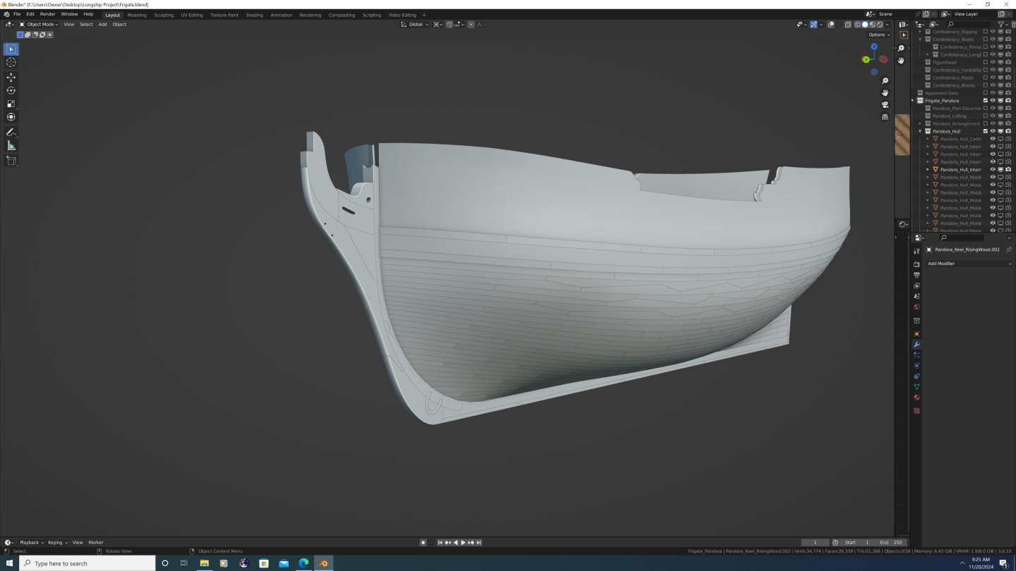
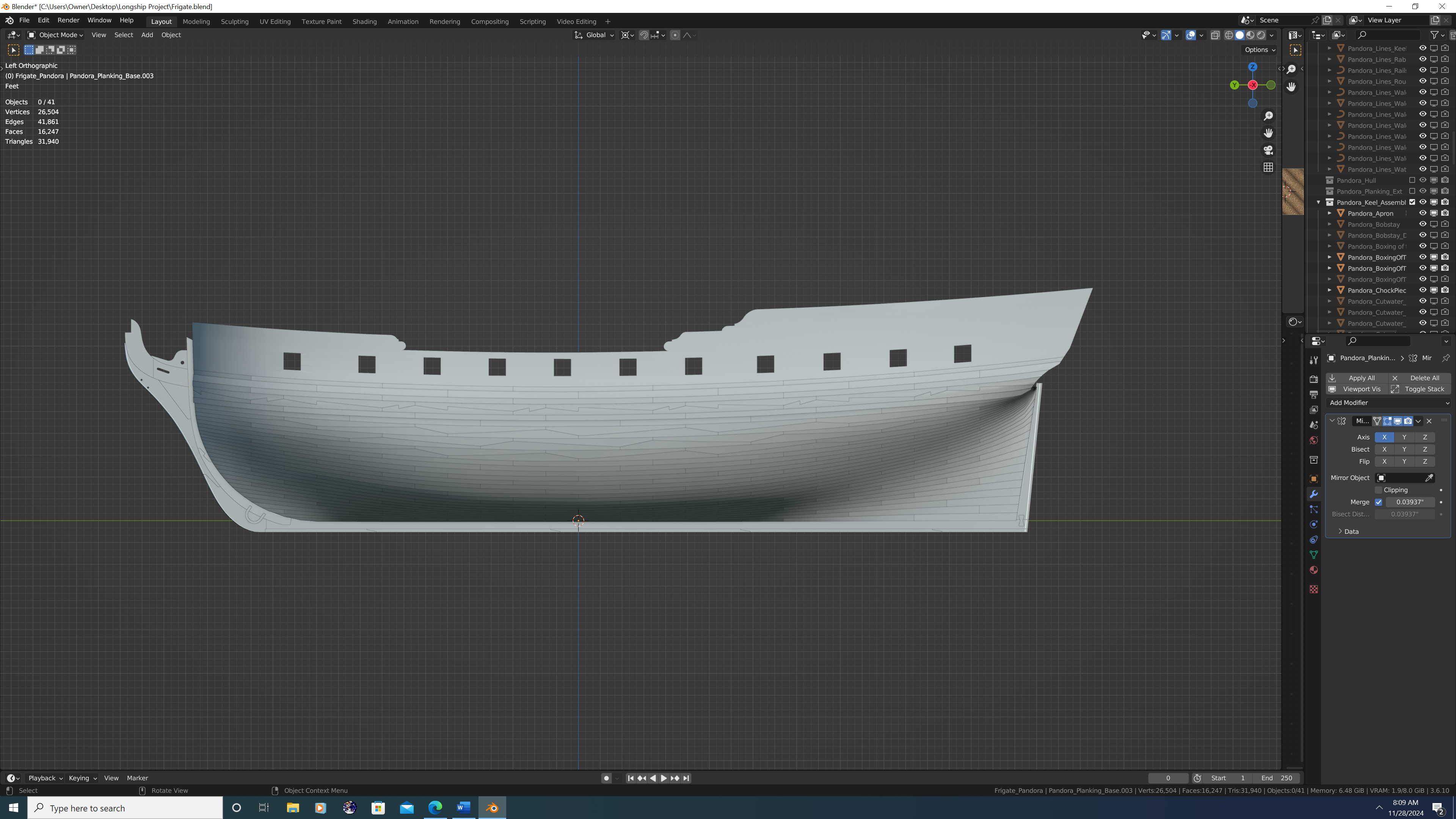
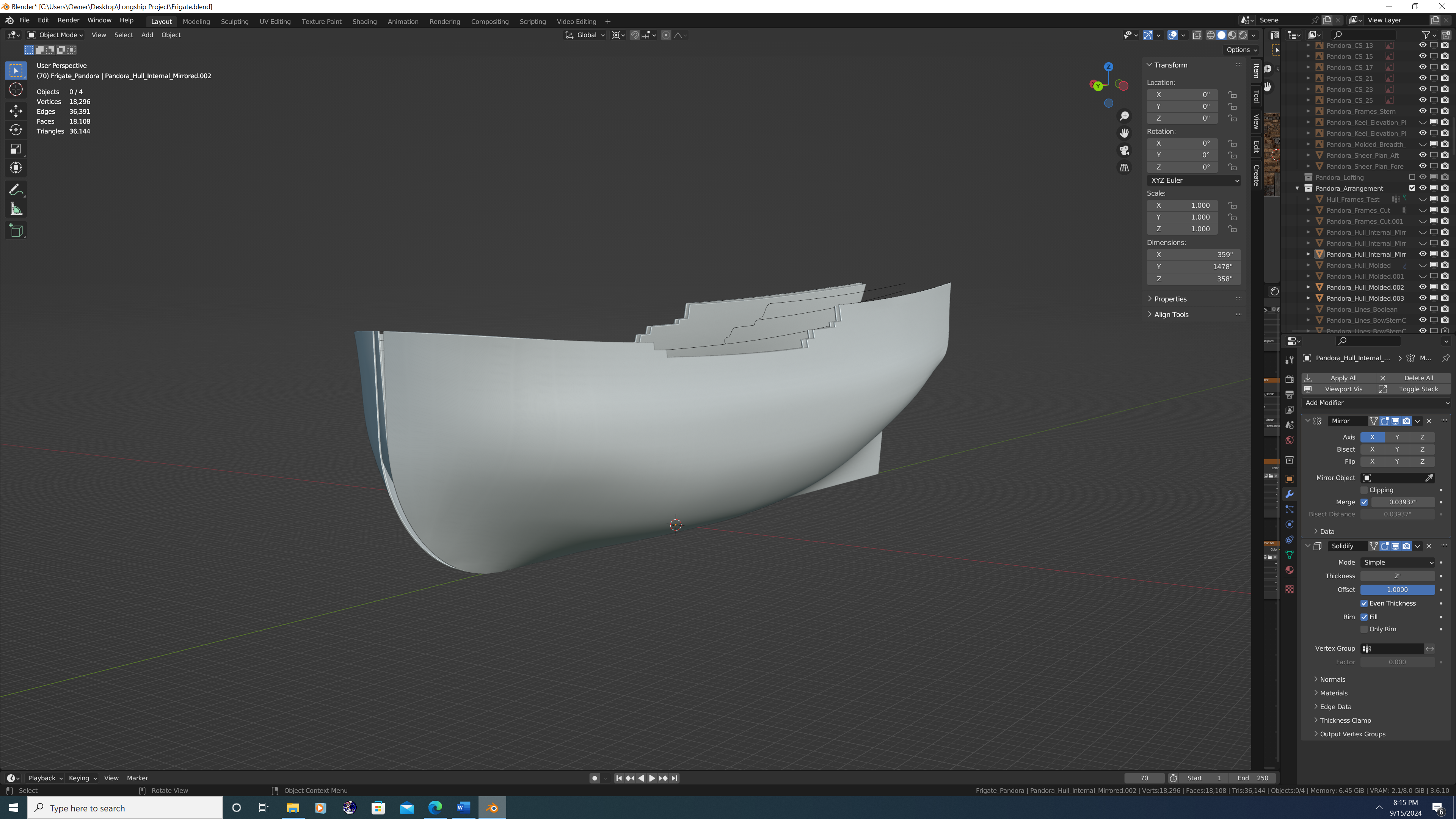
Current state of the project - I will bridge the gap in an upcoming post, but presently, I'm finishing the external planking.
-
And yes, I know that is not Pandora Executive Summary After deliberation, I am taking on the HMS Pandora as my next project. Pandora will be a digital build using multiple software packages, and will be optimized for printed artwork or film. The model will also be rigged for animation for use in film, though I myself do not plan on animating it. The model will be high-poly, and of high historical fidelity which is why it will be documented as comprehensively as possible here on the Model Ship World website. The targeted accuracy is a less than 1% deviation from any credible historical source across all conceivable metrics. This applies to all components modelled About this Build Log I think my biggest asset and greatest hope of completing Pandora is you – the MSW community and the overwhelming knowledge you guys (and gals) have of ship building. I received excellent feedback on all three of my previous builds, yet I am chronically at fault of two things, namely: a. Not seeking out advice when I have a question or run into issues during the build. and… b. Not sticking to the topic or theme of the build log. The latter is especially bad. For example: with Confederacy, I began the build log as an actual step-by-step tutorial of 3D ship modelling in blender, then when that became unsustainable, I moved to posting screenshots of my progress accompanied by short update logs and upcoming tasks. Towards the end I didn’t even finish posts that were supposed to be a ‘part 1 of 2’ or something similar. With my 3D longboat, I am proud to say that I have at least finished the project (gallery photos coming soon! No, really, I promise. Lol). However, I opened that topic thinking I would turn it into a showcase of how to correctly turn a single model into multiple boats in a 3D render and have them look convincing. But it turns out that doing just one was hard enough. Fact is, I simply need more overall discipline in my work. And Pandora is going to be an absolute BEAST to model correctly. I don’t expect her to be perfect – that would be an impossible standard – but I do expect myself to be far more patient than in the past. Framework The theme and structure of this log will be simple: A 3D PANDORA build log. I will still talk at length about how I achieved certain results within the software and call out a few features by name, but I’m going to shy away from anything that is more step-by-step. Not guarding any trade secrets here, it’s just that as my skill has improved, so have the complexity of my workflows. At this point I fear my methods won’t be understood by anyone unless I make a video tutorial. Most of this project will be done in Blender. The final product will be digital, and I find blender to be the best intermediary software between. However, as I’m intending this to be a comprehensive, historically accurate build, I will attempt to be ‘software agnostic’ especially in the early stages of the build. As far as my pre- and post-production needs are concerned, Adobe pretty much corners the market. And even within Blender, I’m making extensive use of 3rd party CAD addons that will allow blender to do 90% of what DelftShip does on the hull front. Margin of Error The allowable margin of error for this project is 1% across all metrics. This is not intended to shield me from mistakes. I will make plenty of mistakes along the way. When I do, call them/me out. Full stop. This is important, not only from an educational perspective, but because unchecked mistakes compound and in extreme cases can even break the project. Rather, this buffer will serve the inevitable reconciliation between imported plans. Even after hours removing distortion in a highly capable software like Photoshop, then further hours spent positioning the images in Blender, there will inevitably be things that won’t line up properly. Excited to get into it with y'all. Stay tuned!!!
.thumb.png.c354f90ad67dca7b2750dc298fbd2ade.png)
-
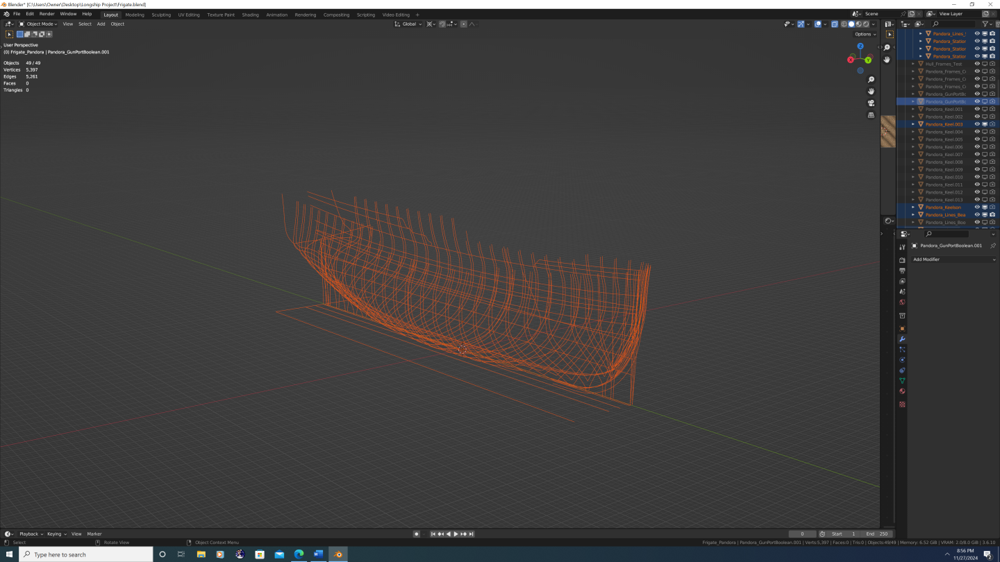
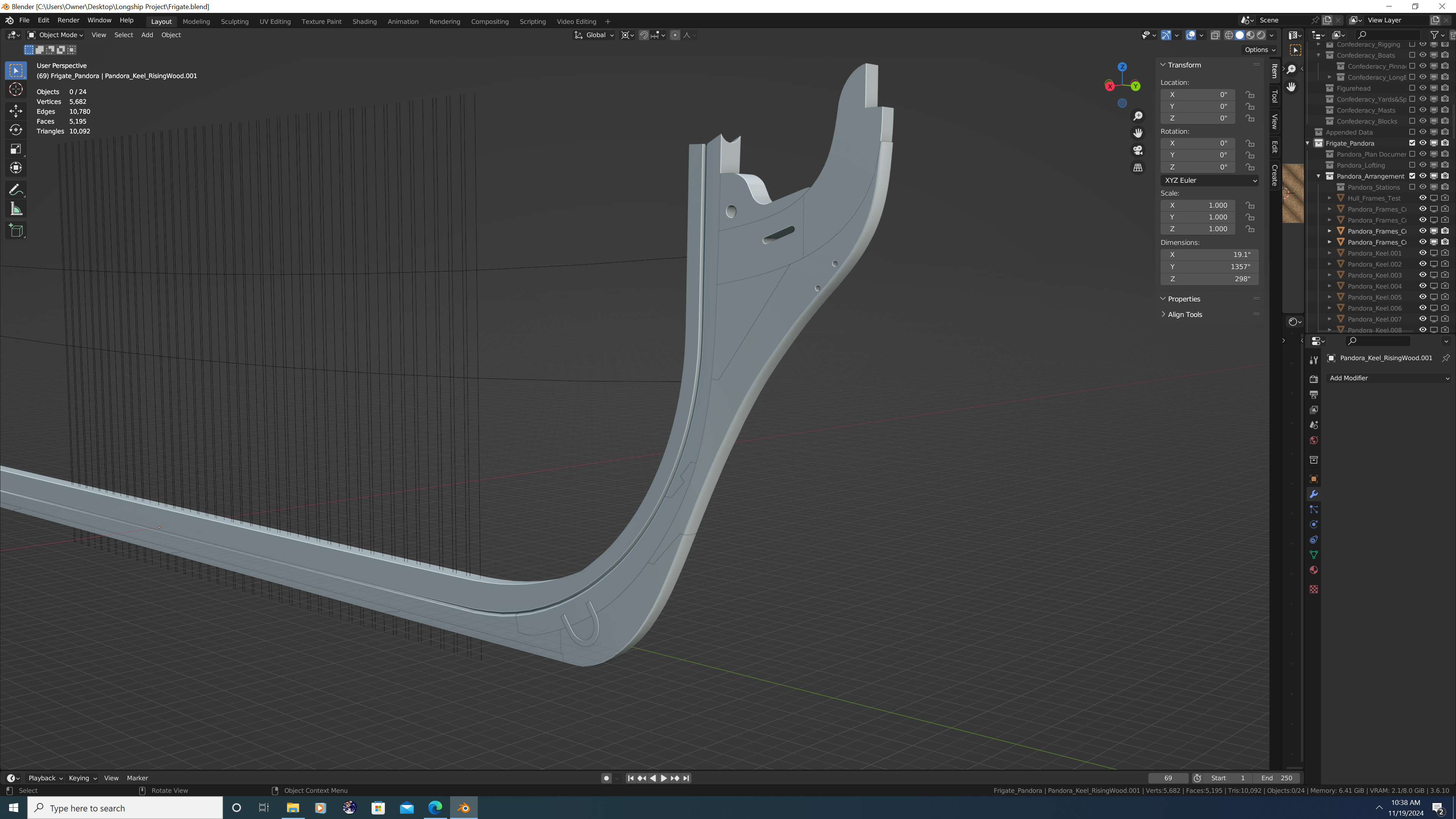
Thanks Thukydides. With regards to your comment above can you be more specific? Are you talking about... The overall profile of the cutwater? (See below) [Also note: model is a work in progress, Apron net yet complete] OR Are you talking about the arrangement of the pieces themselves? (see below) I've seen plenty of examples where the general shape of the cutwater/knee of the head looks as depicted on Pandora (Swan and Porcupine class post ships almost all have the same profile) so I'm guessing you are talking about how the particular pieces are arranged, correct? Assuming you are talking about the latter, where do you think the error lies? I'm of the general assumption that - where possible - fewer overall pieces are preferred from a stability standpoint - which is why the lacing/mainpiece is a single piece of wood, and also why the bobstay holes were cut there and not in a dedicated bobstay piece. Also, remember that these are small ships, and it is perfectly plausible to get each of the components above from the trunk of an oak tree. Anyway, please elaborate on which line you believe was marked off incorrectly, and how you think that might affect the design. Happy to take any feedback under consideration. If it helps, my initial question was if there is any 'sandwiching' that occurs between the boxing of the stem and the gripe, lacing, chock, and gammoning piece? Thanks again, -N


-
@Arthur Goulart - BTW, I didn't mean to seem negative on Rhino.... still a good software, and I'm excited to follow your build.
-
@Arthur Goulart No - most people here use Blender, especially as of late. @Loracs To each his own, but personally, I'd recommend Blender... Rhino may be easier to learn, but it doesn't come close to Blender in terms of features/functionality. I say that honestly and with no ego; it's simply a fact. Blenders' actual competitors are pro studio software like Maya or 3DS Max, but Blender is free. And as a newbie, don't you ultimately want a software you can grow into? Again, to each their own. Best of luck whatever you decide, -Nate
-
@Gregory and @druxey - Thank you both! It was quite eye-opening to learn just how informal and variable stem construction was, especially compared with how precisely designed, documented and measured other components were. Scantling tables give us precise dimensions for gun ports, height above the decks, etc. One could write a novel on room and space calculations. But the stem pieces? 'Well, that depends largely on the shipyard and available timber.' Like, really??? Don't get me wrong, as a 3D artist, I enjoy modeling the parts where I have more creative leeway. I'm just surprised, is all. Anyway, that's not to suggest I'm going to go completely off the cuff. What I think I'll do is to study up on multiple types of stem construction for similar ships of that period, that way I can ensure all the small joint details of my version of Pandora are historically plausible, if not historically accurate. Thanks again, -N.
-
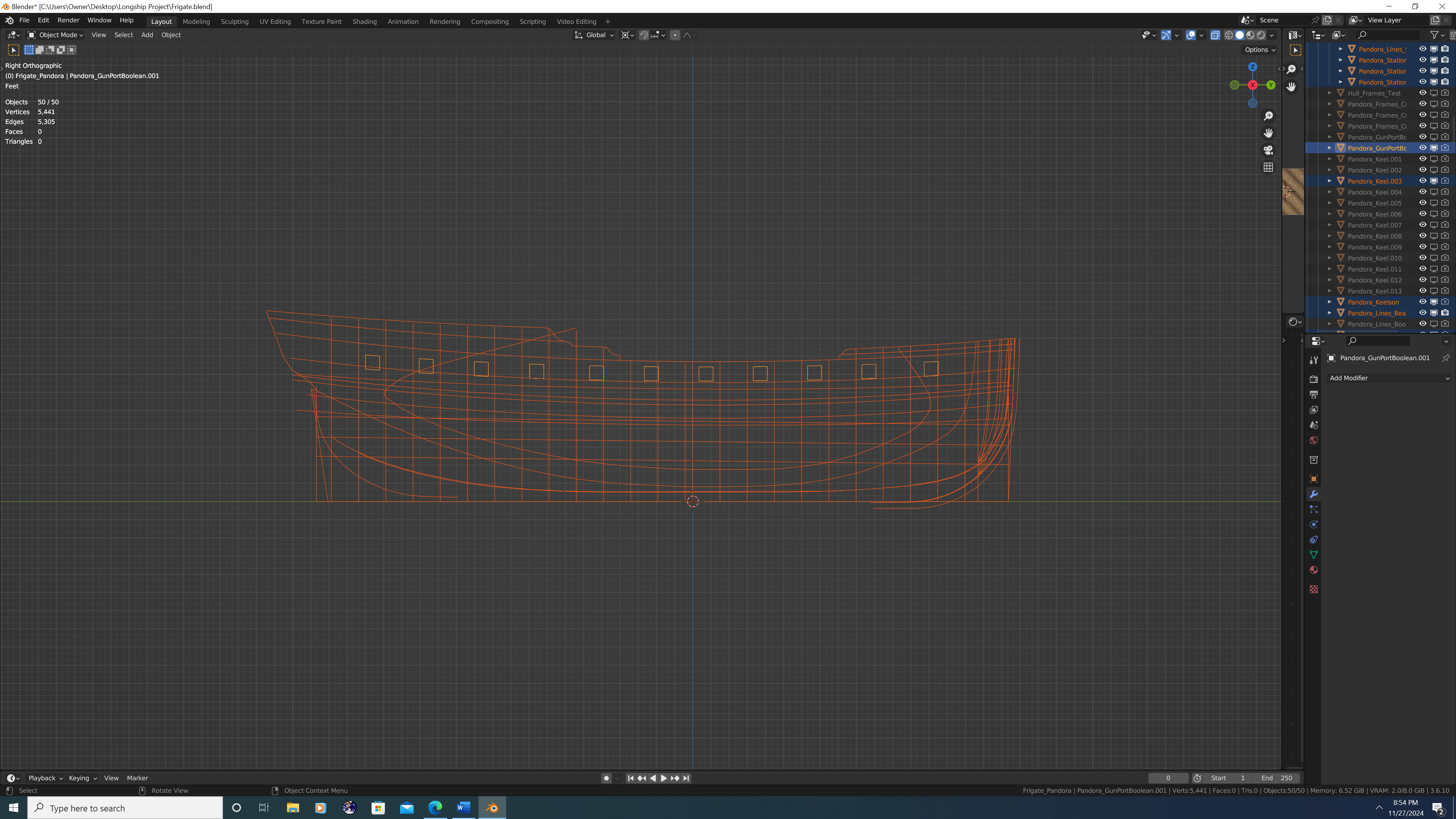
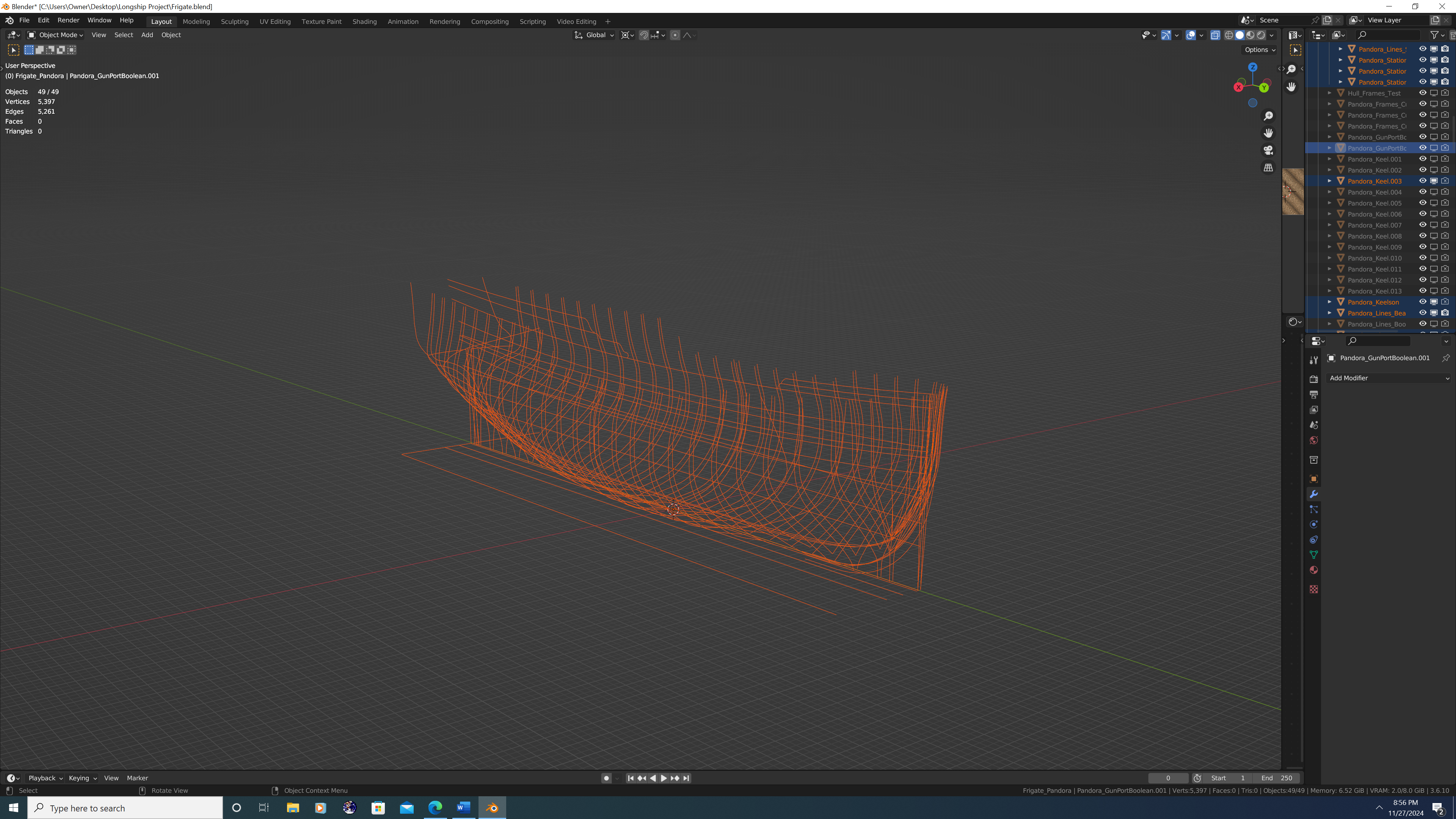
G'day Friends, I have a couple questions regarding the joints of the keel and cutwater pieces. These pertain to my historically accurate build of the HMS Pandora, though for the most part these are very general questions: 1. Boxing of the Stem. I was led to believe that these pieces have this name because they actually clamp or 'box in' something - my question is what? Do they box in the back ends of the gripe, cutwater, stemson, gammoning piece, and gammoning knee? Or do they box in the front ends of the apron pieces? Or both? 2. Joint Between the Keel and Rising Wood. I know things become somewhat fuzzy when talking about the rising wood and various deadwood components atop the keel, so for simplicity's sake, I'm only asking about the wood inboard of the can't frames of the bow/stern; I'm talking about the rising wood that supports the perpendicular frames. It seems to me that the rising wood is a separate piece than the keel, but I don't know where that transition occurs - does the transition happen at the back rabbet line or at the inner (upper) rabbet line? I assume it's the latter but I would like to confirm. 3. Horseshoe and Dovetail Plates. How do the horseshoe and dovetail (a.k.a. fish) plates interact with the copper plating? Are these pieces later covered with copper link the rest of the ship that sits below the water line? If so, how is that done? Are the plates recessed into the pieces they hold together so they are essentially flush with the outer surface? Are they just very thin to begin with? Were they themselves made of copper on later vessels? Thank You!

-
@druxey - Thank you so much! Yeah, I agree. Good news is I started this build using RMG plans wherever possible. However, I didn't in this case because I wasn't sure how much internal variation can exist between ships in the same class (i.e. Porcupine vs. Pandora) and I thought the RMG only had the Porcupine on their site - I might've just missed Pandora's though. Regardless, I'll use the image you provided. It's also got the benefit of being a continuous plan, so I don't have to worry about scaling and accounting for distortion separately on both halves of the ship (a true nightmare lol). Thanks again, -Nate
-
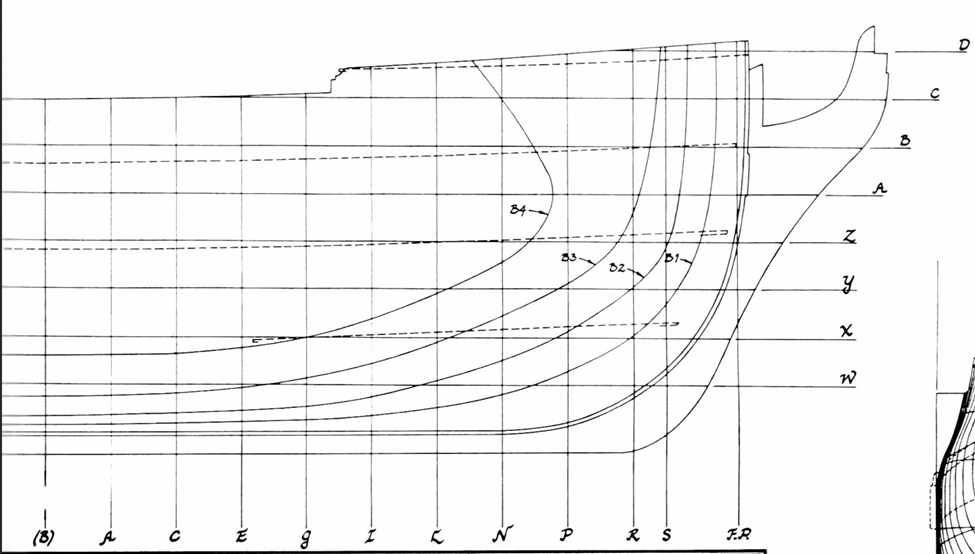
Hey folks, Super simple question here that I probably should, but don't, know the answer to: On the plan below (HMS Pandora), are the dashed deck lines represent the middle of the decks, or the point at which the decks meet the inner hull/planking? I know the decks are crowned slightly and have a cross-fall out to the waterways, so I'm asking if the lines represent the crowning of each deck or the cross-fall. I'm guessing the crowning, but just want to confirm. Thank you all, -Nate
-
Type VIIC german U-boat 3D model
3DShipWright replied to herask's topic in CAD and 3D Modelling/Drafting Plans with Software
Very well done, Denis! I don't know if you are a professional 3D artist or a hobbyist, but your skills are clearly at the pro level, so the critique/feedback I will give you is the same that I would give to someone in the industry: Tip #1: Drive your Edgewear with the Material's Normal Map I recently found out that in addition to plugging in a noise texture to your bevel node(s), you can also plug in the normal map. This is especially powerful on woods as now the edgewear will not only appear on the edges of physical geometry, but also on baked geometry (i.e. the wood grain). This works on metal as well to a lesser extent. I'll give you a quick before and after comparison in a moment, but first, here's a shot of the edgewear portion from the dark blue wood material as seen on both my Confederacy and 3D Longboats projects. Note that there are two methods of edgewear. One just uses a single bevel node, whereas the other uses two bevel nodes, set to different samples mixed with a MixColor node set to 'difference'. I'm using a hybrid, but what I'm about to show does require two bevel nodes with the Normal plugged into only the higher sample node. Figure #1: My edgewear node setup Here's what the bevel nodes look like with/ without normal map comparison: Example a. without normal input Example b. with normal input Now obviously, I am going for a far more 'beat up' look than you are, but you get the idea. Tip #2: Bake your Bolts Specifically in terms of the U-boat, I would go ahead and bake any bolts/screws along the hull into the normal map, even if you plan on keeping them as part of the 3D mesh. In conjunction with tip #1, this will allow you to add minute amounts of rust/warp/damage to everywhere there is a bolt on the hull. Use sparingly, but its an awesome effect. No picture here, as this is really an extension of tip #1.... Tip #3: Add Wet and Standing Water OR Caustics (situation depending) From a texturing perspective, the drawback of a submarine is that it can be depicted as both floating on the surface or submerged. And the special effects that will really bring your model to life, can only exist in one stage or the other, not simultaneously. These effects are standing water or underwater caustics. Example a. Standing puddles and wet spots on wood. I've deliberately overdone it here to demonstrate. Blender Guru has a great tutorial on this, in fact, I'm guessing you've already seen it or already know how to do this, but here's the link if you need it: Example b. Caustics on the top of the hull when submerged. A bit hard to see from the image, but caustics on the hull is going to be key. The trick is to NOT have the caustics as an emission shader in the actual hull shader. I tried this once and it failed miserably. Blender's caustics systems also don't function well with EXR/HDR setups. My solution gets into lighting and environment artist pro-tips, so I won't go over it here. But if you're interested, DM me and I'll be happy to share. I spent weeks figuring out how to get the caustics, god-rays, murkiness and particle systems and water plane to all play nicely together, and I think what I learned would really help to showcase your submarine beautifully. Summary Regardless of whether or not you implement any of these, your U-Boat is outstanding. I continue to be blown away by the quality of your work. In fact, got a couple questions of my own. Feel free to DM me so as not to derail your thread here if you want, I just figured other artists may want to know this as well: At the beginning of the materials thread, you spoke of a 'mask' on where the various paint colors were applied. Am I correct to assume that means your texturing work is being done in an external application like Adobe Substance Design/Painter or the Marmoset Tools? If not, are using the RGBA channel method inside of Blender? A general answer will suffice, I'm familiar with both. You appear to be a bit of an Enigma (U-Boat pun intended) in that the way you talk about texturing I would peg you as a real-time application artist - Unreal or Unity (though let's be honest, Unity may not be around much longer following the runtime license fee model they had to walk-back). Yet, you've managed to make what is essentially a giant capsule into a 4million vertex model that I'm pretty sure would smoke even a RTX4090... Lol, Just curious. Once again, awesome stuff! -Nate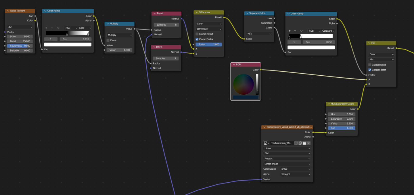
.png.28966744128fad562ba50a2e0b774a0f.png)
-
HMS Pandora 1779 in 3D
3DShipWright replied to ppddry's topic in CAD and 3D Modelling/Drafting Plans with Software
If anyone's interested, I'm about 1 month into a new 3D Pandora build as well, just haven't started a topic on it just yet...
.thumb.png.f2992038a58831558946e9b6ed50d58a.png)
-
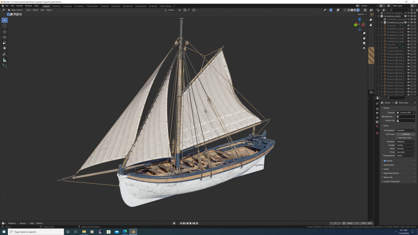
3D Longboats in Blender
3DShipWright replied to 3DShipWright's topic in CAD and 3D Modelling/Drafting Plans with Software
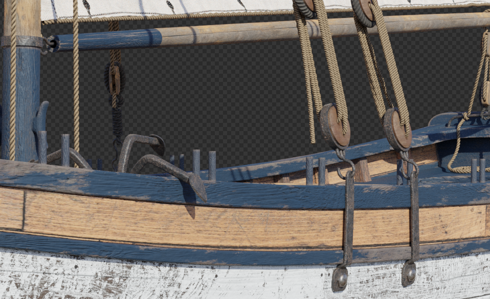
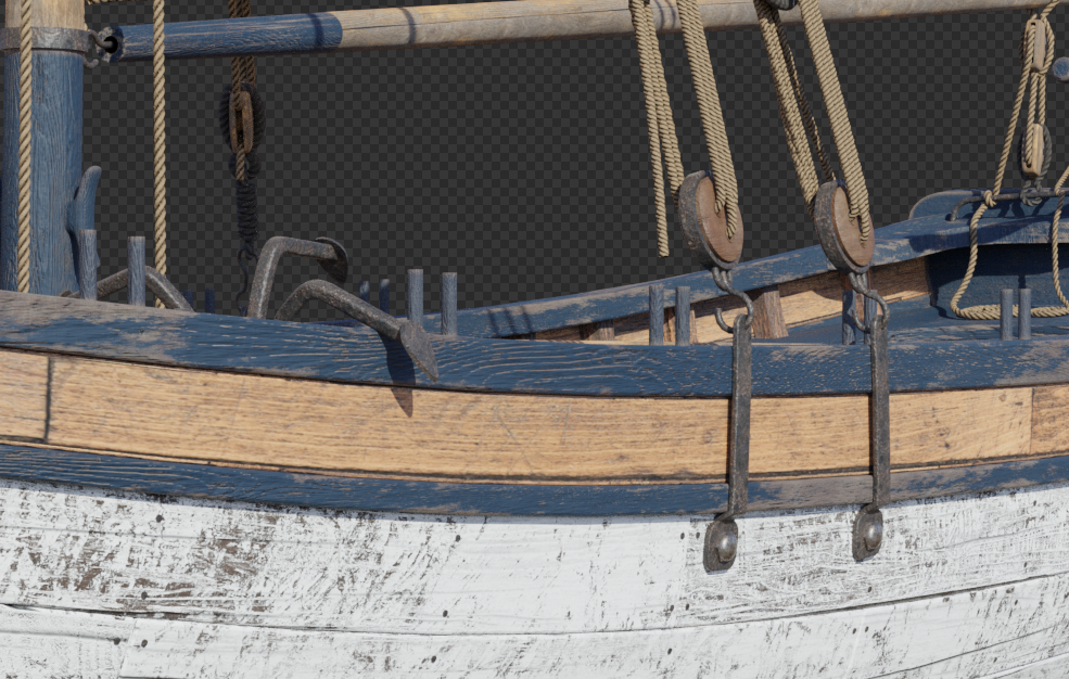
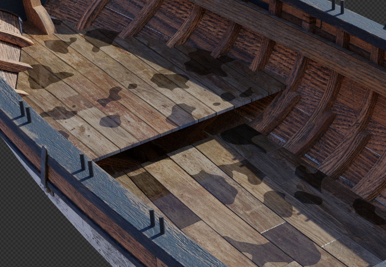
I must say, I've gotten far more enjoyment from doing a small boat than I ever thought I would. My initial thought around the ships' boats was that they were going to be merely one of the fittings (speaking in terms of time and energy I planned to spend on them). While I definitely put TLC into things like the anchors, capstans, helm, etc. I don't look at those as stand alone renders, and I keep the overall level of detail congruent with that of the entire vessel. That said, I've always dreamt of doing a ship model that would hold water (pun intended) whether you were looking at it from a distance of 2 feet or 200 feet. At that's what made the longboat so rewarding. What I like about this project is that it was the perfect amount to 'bite off'. It was just big enough to justify all the little texturing hacks like: edgewear and scrapes along the hull vector displacement in the individual rope textures standing water on the cockpit and floorboards 3d trunnels along the entire outer hull simultaneous transparency, translucency, subsurface scattering realistic sheen and anisotropic distortion on the sails people! At the same time, because it is a small vessel overall, I have a realistic chance of actually finishing the dang thing lol. Anyway, I hope y'all enjoy - I look forward to posting full resolution images when I complete the longboat in a few weeks' time. Best, -Nate.png.4e31a8a296b40e3fbe77739857df0628.png)
.png.6a7345f8271ccd08350218f61597df26.png)
.png.4fe537a46b66fdd8d22e54b215c707d1.png)
.png.80f48e0bc435dd70d90ae771743b691f.png)
.png.f7fc0cd93adb40f5099a5e88da4745aa.png)
-
3D Longboats in Blender
3DShipWright replied to 3DShipWright's topic in CAD and 3D Modelling/Drafting Plans with Software
Sails completed!.png.9066993a9fea17123c3e9273705af9ad.png)
-
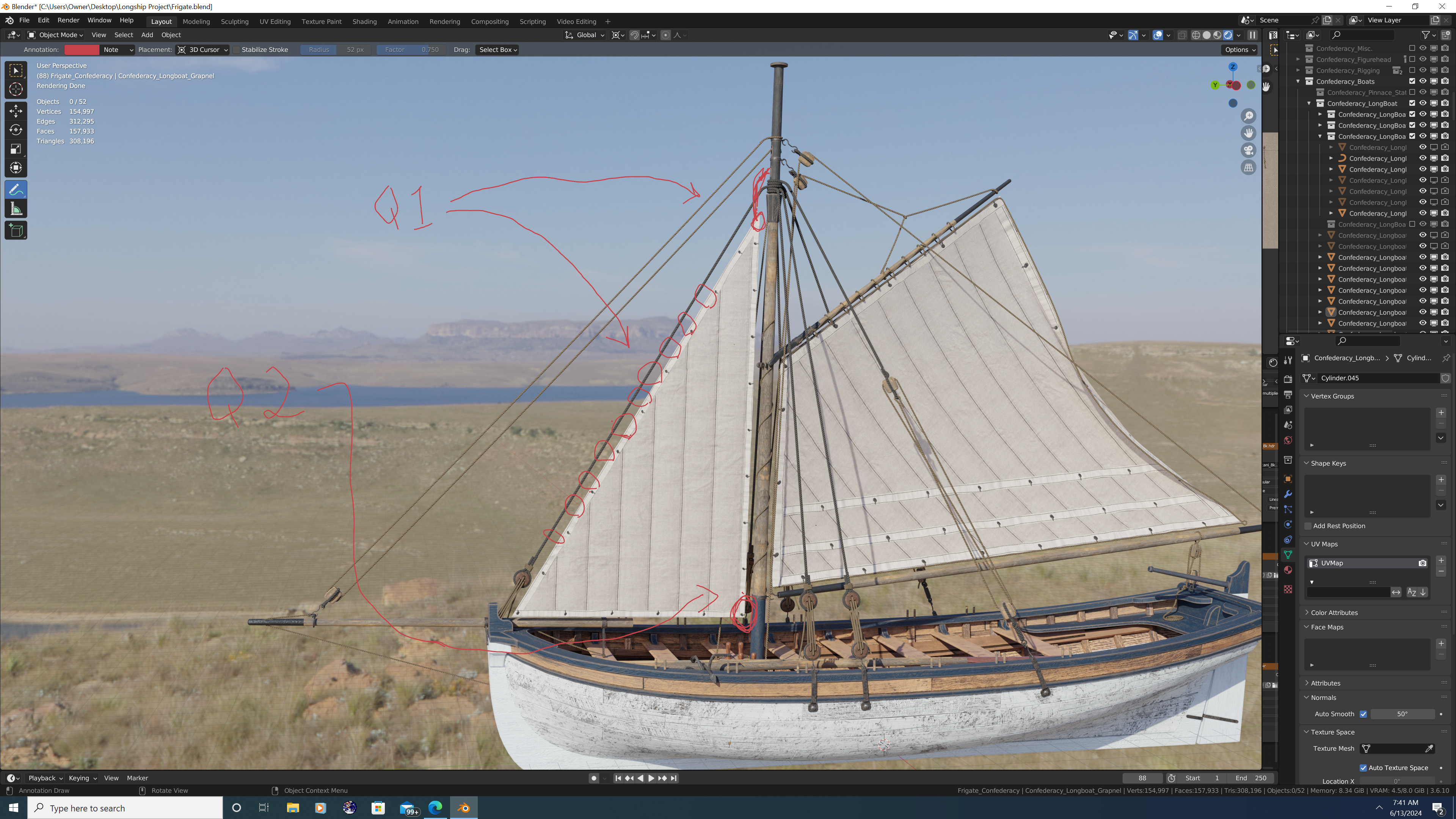
Hey folks, I hope this is the correct place to post this question. So I've been working on a fully rigged longboat under sail, and have run into a couple logistical issues I was hoping to get some help with: 1. It looks like the foresail is 'looped' (via fairleads?) around the forestay so that when raised, the stay provides the luff of the foresail additional stability. However, the sheave through which the foresail halyard runs appears to be higher on the mast than where the forestay is secured. My question is: Do I have the general configuration correct, and if so, how does the foresail halyard block not conflict with the forestay when the foresail is raised (See picture)? 2. Simpler question: When raised, where does the clew of the foresail belay to on the boat? I ask because once I model the flag halyard, all four pins on the waist thwart will already be in use, and the foresail/flying jib halyards belay to the shrouds above the deadeyes... so there doesn't seem to be much room left unless a pin is used twice or the clew belays around a thwart or the lower mast itself. Thanks in advance, -Nate

-
- 1
-

-
3D Longboats in Blender
3DShipWright replied to 3DShipWright's topic in CAD and 3D Modelling/Drafting Plans with Software
Trying out some improved sail and sail rigging techniques... It's nice to have a small vessel like this longboat to use as a staging environment before starting the mammoth project that will be rigging Confederacy..png.a88020632d0ff2e94d3bf2d58578408d.png)
.png.158d5e6f77579bf18405608e9d9212b1.png)
.png.abb9afb661aad8c21e84b47deb41d2b5.png)
-
3D Longboats in Blender
3DShipWright replied to 3DShipWright's topic in CAD and 3D Modelling/Drafting Plans with Software
"Quite the contrary, ol' sport - it's those insignificant details that are by far the most important." - Sherlock Homes, Sir Arthur Conan Doyle.png.9549d34b7431e48f1266f450bdf14fd5.png)
-
3D Longboats in Blender
3DShipWright replied to 3DShipWright's topic in CAD and 3D Modelling/Drafting Plans with Software
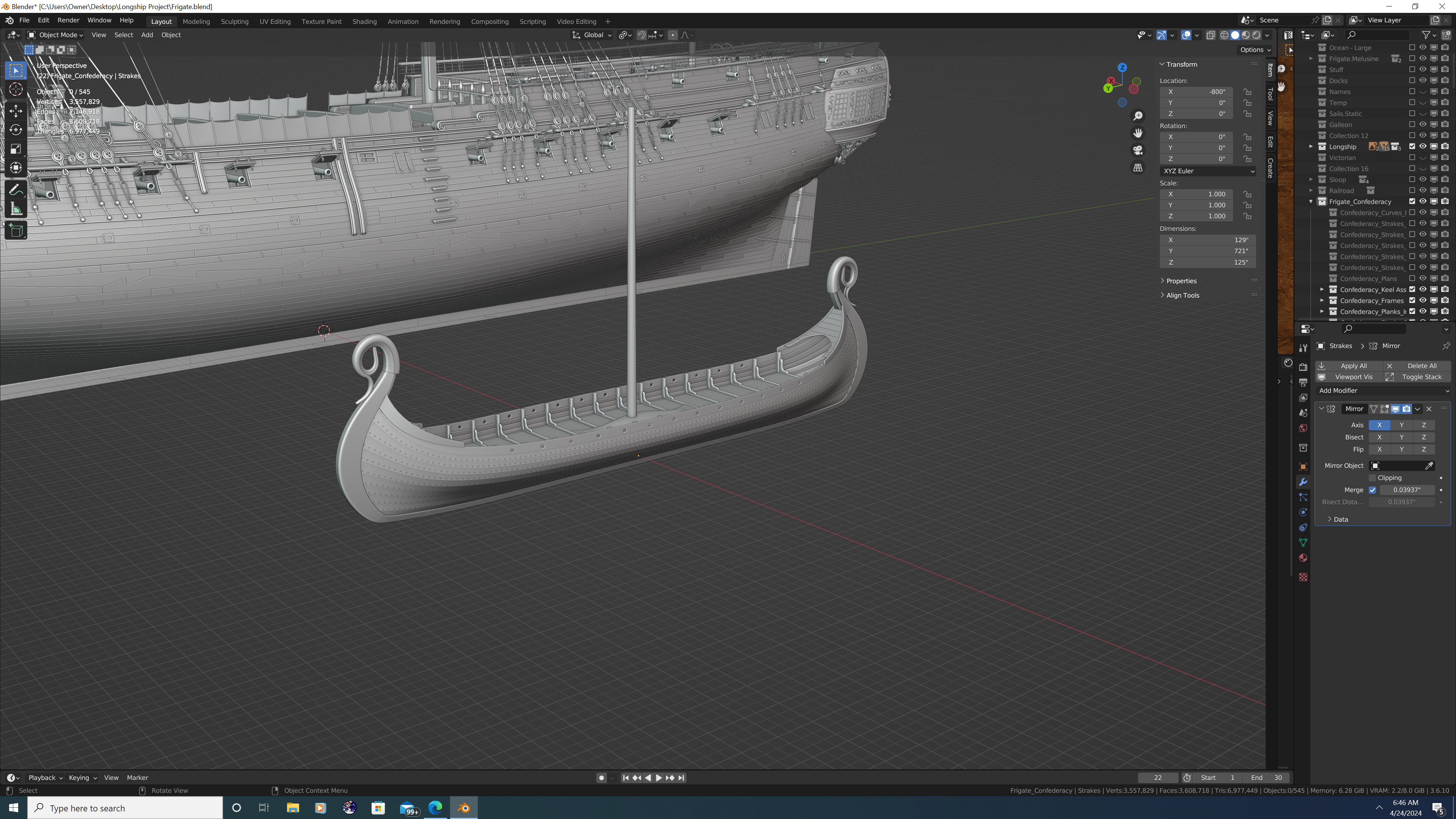
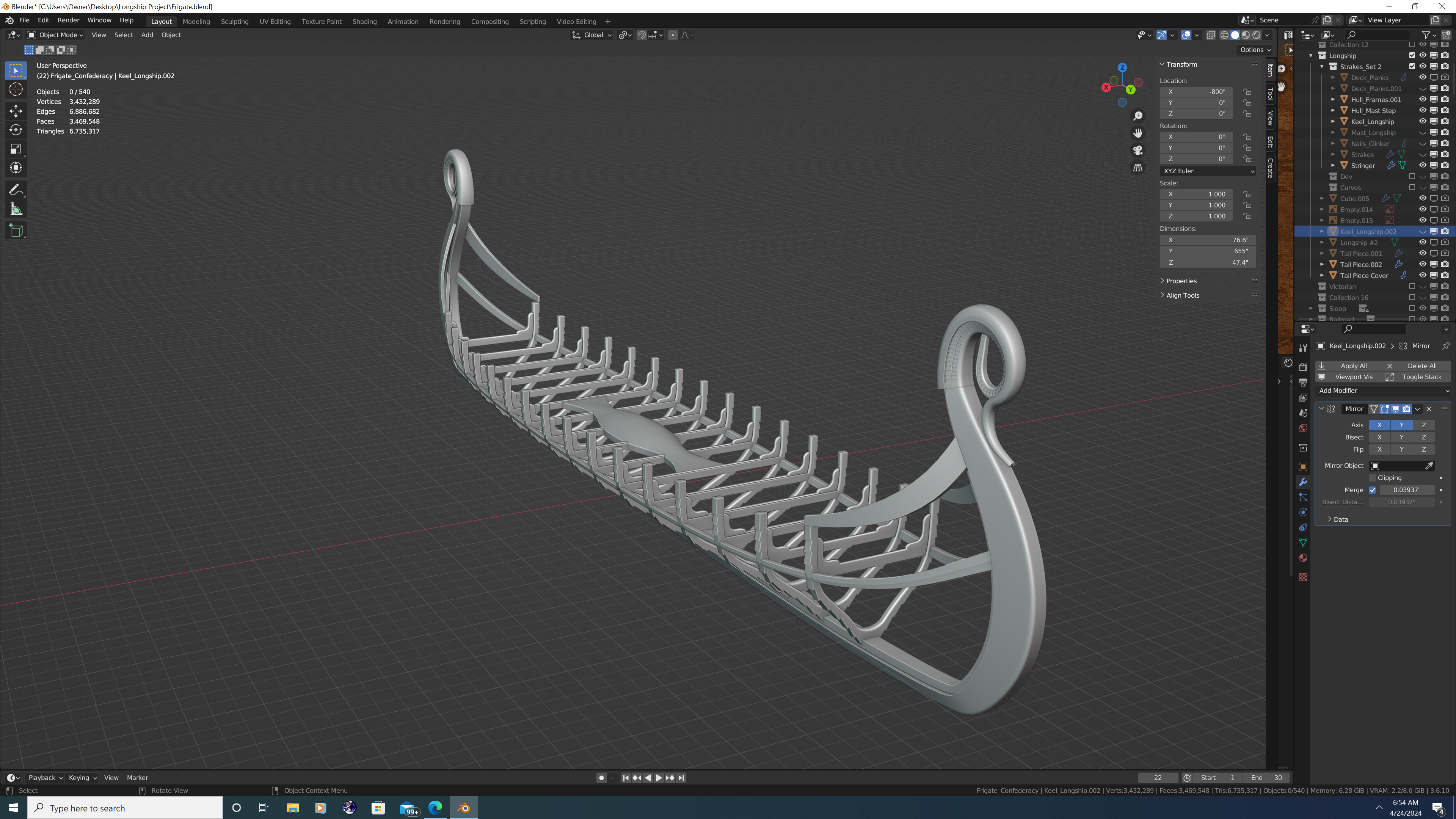
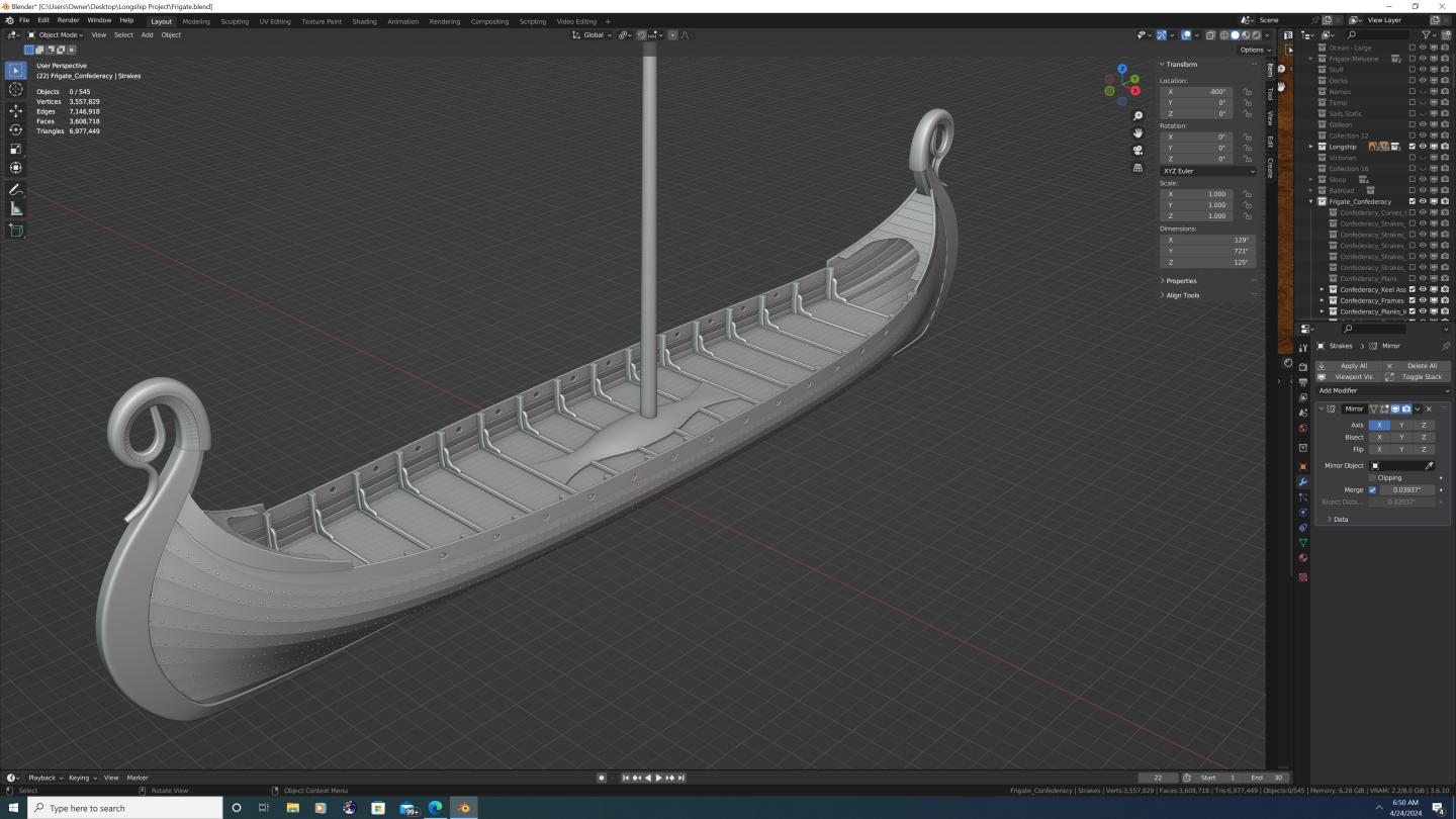
Part 2: Components Hey folks, Picking up where I left off, the second and (I believe) the most important way to add variances to the long boats is by changing up the components that make up each copy to make different versions of the boat. A pre-requisite to this of course, is to build the model in pieces that can later be swapped and altered. The initial version will be insipred by, but not pirated from, Chuck's Medway project. To that end, I have actually sourced my own versions of royalty-free plans online, and while there are definately some similarities, there are also some fundamental differences which include: 1. Overall Length of the Boat: (31 feet compared with Medway's 28 ft longboat 2. Thwart and Frame construction: The plans I found call for the same split thwart style along the waist, but actually call for cant frames near the bow and cockpit. I carefully verified this, as angled frames are/were unusual on longboats 3. Cockpit configuration: On the Medway boat, the aft-most bench touches or nearly touches the cockpit bench/seat (name?), and on my model, there is a more pronounced gap 4. Rudder: My longboat has a shorter rudder paddle 5. Spar dimensions: Plans for the mast, bowsprit, spanker boom, and spanker gaff were all taken from the AOTS book, and modified to suit a cutter-rigged boat. And now for a photo montage... a. Keel assembly (ignore the texturing on the knee - I will fix later) b. + Thwarts and Frames c. + Risers and Transom d. + Floorboards and Cockpit Floor (note the standing puddles - I had fun with that visual effect ) e. + Seats, Cockpit Bench, Windlass, and Bolsters f. + All Strakes, Wales, Mouldings, Caprails, Oarlocks, and Angle Braces g. + Rudder (with tiller and gudgeon/pintle straps), Chainplates, and Grapple f + Lucky Jack! Getting ahead of myself here, but this model will also include detailed character models when finished That's all for now, smooth seas lads (and lasses) -Nate.png.29f5d50bb55cac42985726aaa14a533e.png)
.png.22bab80127bf1f6ac1a6fc344a164022.png)
.png.fad0fd0969f0280719ea365046534234.png)
.png.9ba0ed1930f2f52bb5bd251c6f5820c8.png)
.png.27605455802040b97c32f7cd6eeac5d0.png)
.png.2977ddb49475382ea9b72830106ea68c.png)
.png.9a4493c35908188a5b63b82736df35db.png)
.png.cb745f05898b2364163baee0c46b6bb5.png)
- 13 replies
-
- 11
-
-

-
3D Longboats in Blender
3DShipWright replied to 3DShipWright's topic in CAD and 3D Modelling/Drafting Plans with Software
@druxey - I was curious, however, later 18th century longboats often seem to be twin masted and lateen-rigged as opposed to the earlier cutter rigged. Do you happen to know the reason for the change? Thank you Sir, -Nate -
3D Longboats in Blender
3DShipWright replied to 3DShipWright's topic in CAD and 3D Modelling/Drafting Plans with Software
@druxey - Thanks for the kind words. Fun fact - The name Pinnace was derived and evolved from the original Pinnacle, and historical documentation shows that Pinnacle was still the 'official' name for this type of longboat, at least through the 18th century. Some elements of my 3D longboat model are based off of the AOTS H.M.S. Pandora's Pinnacle (pg. 126-127) -
3D Longboats in Blender
3DShipWright replied to 3DShipWright's topic in CAD and 3D Modelling/Drafting Plans with Software
Haha - I know exactly the scene you're talking about! I think it's a little less egregious with more 'modern' ships because the ships in a WW2 fleet, in theory, would be more similar than say the Royal Navy's fleet at Trafalgar. Particularily bad is a certain shot in one of the Pirates of the Caribbean movies, where all the East India Co. ships are not only identical, but their yards trimmed to exactly the same angles and the sails' fluttering are completely synchronized... now that's lazy! -
Hey Folks, I decided to flush out the longboat that features in my Rose and Confederacy projects. This 31-footer will be similar to my other endeavors in terms of realism and texture quality, and will have every single piece of wood, metal, and rope modelled individually. However, note that I’m using the generic term ‘longboat’ instead of referring to its specific type/function (barge, launch, pinnacle). The reason being, I’m going to attempt a one-size-fits-all approach. As a bonus, I will make the model and all of its components available for free and without restriction to anyone that wants it. [Stepping onto my soapbox] Back to the one-size-fits-all thing – I know this may sound like a bad idea. Nearly everyone I know hates the use of ‘generic’ or ‘copy/paste’ models in CGI. And this goes far beyond the naval/nautical realm. In fact, the whole anti-CGI or practical effects only movement in Hollywood is a response to bad or lazy CGI. But therein lies the point: what audiences actually dislike isn’t CGI, it’s bad CGI. [Stepping back down now] But what on Earth does any of that have to do with a simple longboat? Well, as I mentioned before, I ultimately want to use Rose, Confederacy, and a ship-of-the-line that I’ve not yet started to make photorealistic renderings and printable artwork. Specifically, I want to do justice to a complex harbor scene. So imagine Nassau circa 1715 or colonial Boston in the latter half of the 18th century. Both have bustling ports with hundreds of boats and ships. There have been a few films and tv shows that have attempted to bring these environments to life, some of which have even done a decent job of framing, lighting and perspective to make a brief fly-over shot look convincing. However – these are film, and they are counting on the audience having only a few seconds to absorb the imagery. This is why so many of these shots rely heavily on haze, fog, lensflare, low-light or backlighting conditions… these tricks tell your brain what you are seeing is real while obscuring the actual subject of the artwork. Just for fun sometime, pause the movie/show and look at the actual frame. Most CG boats and ships are not that detailed or well done. If there are numerous ships in the scene, it usually only takes a few seconds to realize that they are copies of one another, only posed slightly differently. And studios do it this way for good reason, the time and energy required to do it right would far outweigh the benefit. But creating a realistic, static render is different. My audience will have time to focus on details. Sadly, even I don’t have time or desire to individually model 100 different ships, which brings me full circle to the crux of this endeavor: How do I make a single longboat that can be cloned and easily tweaked to look like many, completely different boats in the same scene? It’s not a rhetorical question, so I began by making a list of variables, in increasing order of complexity… Variable #1: Shared Copies (identical mesh models) with Cosmetic Differences 1. Pose the copies at different angles and direction, for example, if there are two at the same dock, one can face inland, the other seaward. Okay, so this one’s a no brainer. This is required to even build out the scene, and is also useless by itself. 2. Shared copies could have different colors. So if the first longboat has blue trim, the second could have red, and yet another green, etc. This is a good start, but it should be taken a step further. 3. Shared copies could have different skins. This involves changing not only the colors, but also the overall livery. In this scenario, the entire wale on one longboat may be painted whereas on another only the caprail and molding are painted. A third may have a decorative frieze running the wale or on the transom. The strakes on some may be entirely whitewashed, whitewashed only below the waterline on others, and perhaps not at all on a few of them. This method can add a lot of variety while still being fairly simple, as I will only need to tweak certain parts of my textures, and not rebuild the textures entirely – i.e. the underlying wood grain would still be the same on all copies of the longboat. 4. Shared copies could have different textures. The final method of cosmetic variation is to use different texture sets for different copies. This will make each longboat appear to be constructed of different or somewhat different materials. That’s it for this post, will continue in the next post of a discussion of the other two variables, which are - Variable #2 Unique Copies with Differences in Components Variable #3 Unique Copies with Differences in Configurations -Nate
.png.b4e962d40d7fe4d2dd26e1c522b2fab4.png)
.png.75cdf9cab9d0dfc327ea61ef810299d8.png)
- 13 replies
-
- 14
-
-
-
Redoing Oseberg
3DShipWright replied to KrisWood's topic in CAD and 3D Modelling/Drafting Plans with Software
Yes, Blender supports the .svg format if that works. Regarding the published plans question, a few thoughts: 1. I think the reason the pdf documents are gated in this case is so that they can run analytics on who is using their research and for what purposes. 2. I would also argue that research by itself, is not intellectual property. I am in no way diminishing the scholars' effort, but the work was derivative; it can't be patented. And if there's anything I know about academics, it's that if they could monetize their work, they would've. To draw a parallel to the NMM in Greenwich, the RMG does sell copies of admiralty plans because they hold accurate, original copies of the plans and the ships themselves (other than those they stole) were property of the English government. Even so, the licensing is unrestricted aside from commercial use, and their site says simply to credit them and contact them and they may "support education and scholarship and encourage research in our collections by waiving licensing fees for certain uses." 3. Finally and most importantly - To even be considered a 'reproduction' the copy must be the same media or type as the original. To my knowledge, nothing published on the Oseberg site has been digital cad files for the purpose of 3D printing, nor making templates from which to construct a model ship. Think about it this way, they transcribed a physical object into print media, now you are transcribing print media into digital media. If anyone is owed royalties here has been dead for over a thousand years. So yes, I would recommend crediting your source material wherever possible. I also think it may be courteous to thank them via an email, a good review, or a small donation (whichever you feel appropriate). But I don't think sharing a free document for purposes of a non-commercial project should even be a factor here. -
Redoing Oseberg
3DShipWright replied to KrisWood's topic in CAD and 3D Modelling/Drafting Plans with Software
Hey Kris, Cool stuff! I'd be happy to do some collaboration with you. I love longships and have even been tinkering with doing one of my own over the last couple of weeks. Let me know if I can be of any assistance. -Nate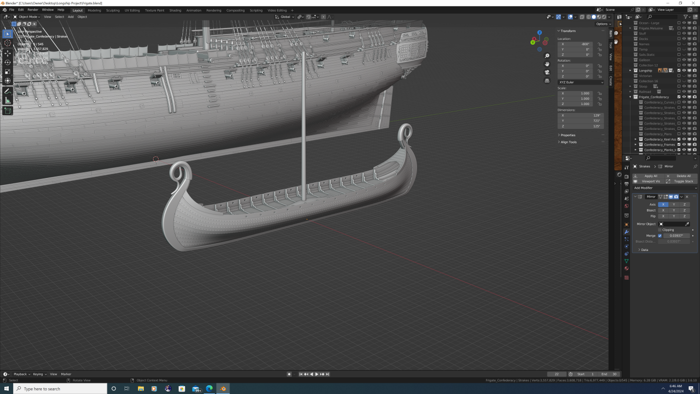

-
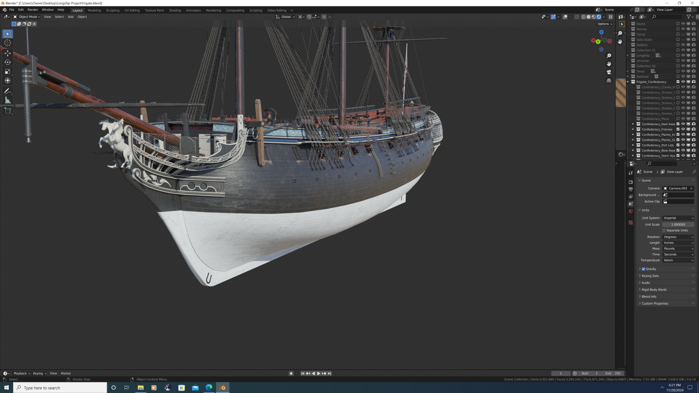
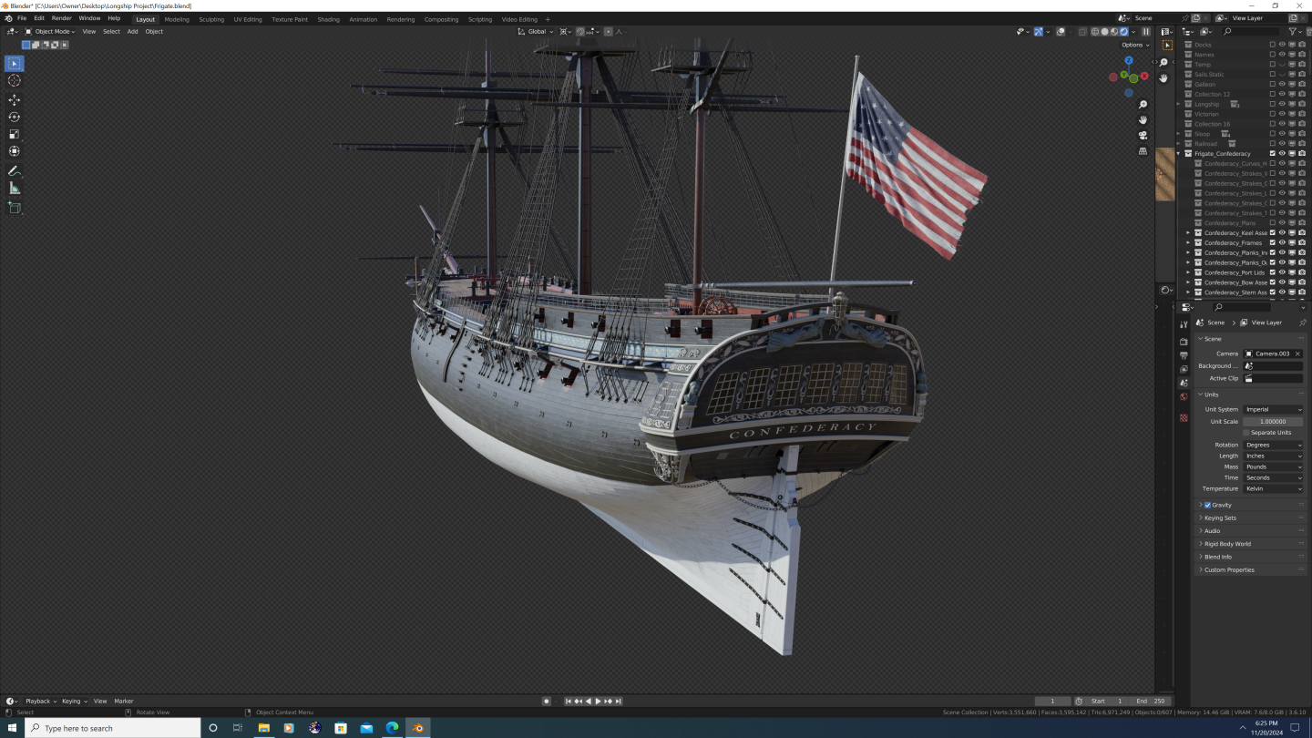
Hi Everyone, So after a bit of a hiatus, I'm back with the first of three major update posts to Confederacy. In this post, I'll cover updates to the bow and a couple of minor enhancements to the outer hull. Change log is first, photos at the end. As always, feedback most welcome! Upper headrail remodeled to taper properly. Pendant joint added at the top. Carling atop the upper headrail remodeled; trim rail now blends smoothly where it meets the rail Lower headrail remodeled as two distinct pieces that follow the hull and connect with the bottom of the catheads Upper and lower headrails are now adorned with decorative reliefs Hanging knees installed beneath the catheads Boomkin holsters installed the upper headrails to support the bumpkins Beakhead platform flattened, height adjusted; position of the doorsand round houses adjusted accordingly Ledges that connect the beakhead platform to the prow grating installed Seats of ease installed in front of the bumpkins atop the grating Color theme of the bulkhead has been updated; doors and roundhouses are now white; decorative motif (white on blue) carried over from the side of the hull Gammoning slots cut into the gammoning knee have been corrected so they aren't covered by the headtimbers Safety netting added to the headrail barricade Tip of the cutwater has been cut back a bit to accommodate the figurehead Horseshoe plates flipped from heel to toe (I had them on backwards originally) Bower anchors haver been upscaled to their (nearly) correct size Chain plates, channel ties, and straps (lanyards) in place on the forward channels; main and mizzen channels in progress Inboard and outboard rings installed on all gunport lids; outboard rings each have their own bones in the armature allowing them to pivot as the rope pulls the port open And now the photos:
.png.e30a775e7328b0f5425ba4df7de239d4.png)
.png.9fa02f561a3c1b3c45d613aed39cddc9.png)
.png.67b61ceadb93bb46dbce27dec20f46fb.png)
.png.0267900e1530d92a7ef350d996c78713.png)
.png.32f543725c5afaa1e6144beded8d2d7e.png)
- 107 replies
-
- 3
-
-
-
- Frigate
- Confederacy
- (and 1 more)
-
@64Pacific - Thank you so much for the kind words. While I won't undersell the amount of time or tediousness of such an undertaking, I absolutely love following the projects of the other 3D artists on this forum and draw continued inspiration from their works. Specific shout outs to @CDR_Ret and @Martes for their continuous updates (both blender users) that keep me engaged in my own projects, even if I'm not as disciplined at sharing regularily. And many other talented artists I many have missed. Finally, from an aspirational perspective, I'm still very humbled at what @herask was able to do on his swan-class (HMS Pegasus) 3D model. It is one of the most comprehensive digital ship models I've ever seen, even among the professional 3D artist's portfolios over at ArtStation. In point of fact, it's that level of detail that I hope Confederacy has when finished. Point is, give it a go! There's a great community here to cheer you on and provide assistance should you need it. Best, -Nate
- 107 replies
-
- 4
-
-
- Frigate
- Confederacy
- (and 1 more)
.png.1acf13ed9c96bae4dd7eea1b1fe9ed2a.png)


.png.fc5e70a3acb9e492d634d2c2ca9b61ab.png)