

ddp
-
Posts
78 -
Joined
-
Last visited
Content Type
Profiles
Forums
Gallery
Events
Posts posted by ddp
-
-
if the model is supposed to represent mid 43 to 44 then can't have the Wildcats as were on til May 1943 then Hellcats in Nov 1943. you would be using airgroups 6 or 10 for that time period.
- ted99, Old Collingwood, Canute and 1 other
-
 4
4
-
-
go thru this link https://www.navsource.org/archives/02/06a.htm to look at all the war time pictures to locate most if not all the life raft positions. the rafts would be painted the same color(s) as the location it is in so can have more that 1 color depending on the camo scheme used.
-
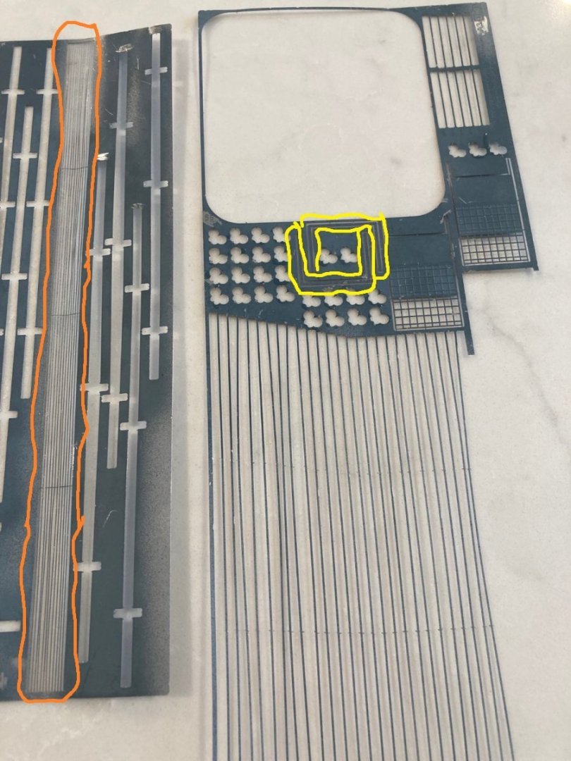
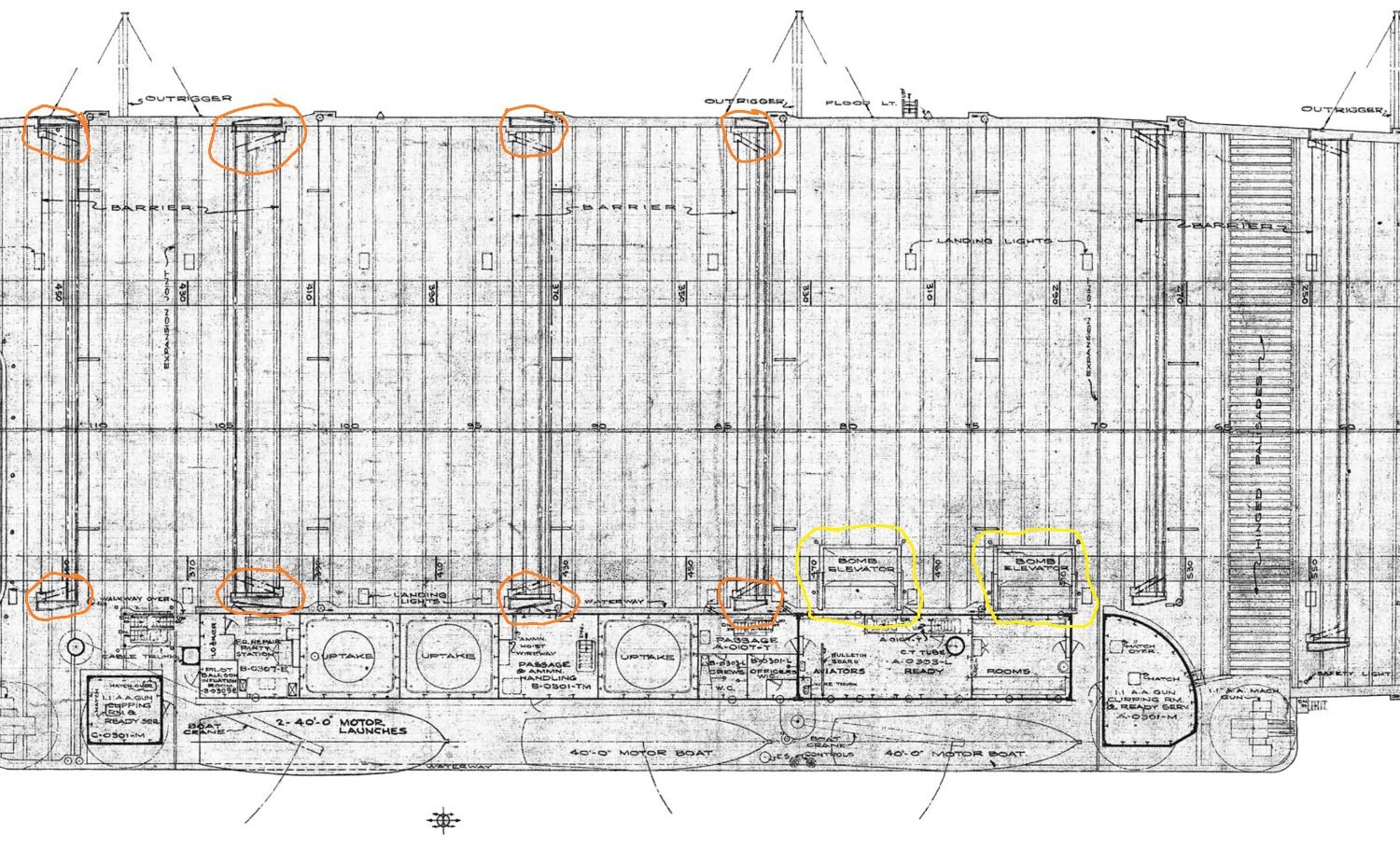
take a look at this link https://www.navsource.org/archives/02/020667.jpg as can just see the 2 bomb elevators.
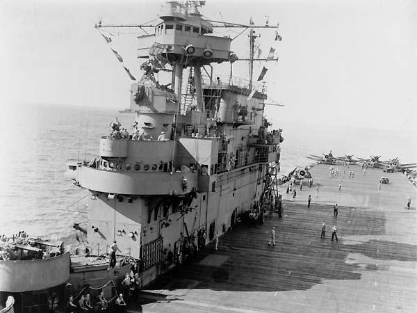
"The "Big E" had her island modified during her July-October 1943 refit. Note new platforms on both the navigation and flag bridges, for better visibility, and Mk.37 dual purpose director (with Mk.4 radar antenna) in place of her former Mk.33. Photo taken on March 20, 1944 from one of her own planes."
- Old Collingwood, Canute, ted99 and 1 other
-
4
-
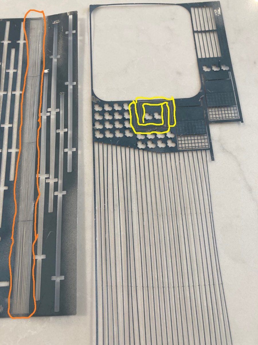
so you are talking about the orange circled objects on the left & the yellow circled objects on the right, correct? can you post a close-up shot of the area you think are "vents" as i think they are the 2 bomb elevators?
on the 2nd picture, is the yellow circled objects the "vents" you are talking about & do you have the orange circled objects in pe or plastic as those appear to be the ends of the crash barriers?
- Old Collingwood, yvesvidal, Canute and 1 other
-
4
-
can you point out the 2 things so we know what you are talking about?
- Canute and Old Collingwood
-
2
-
-
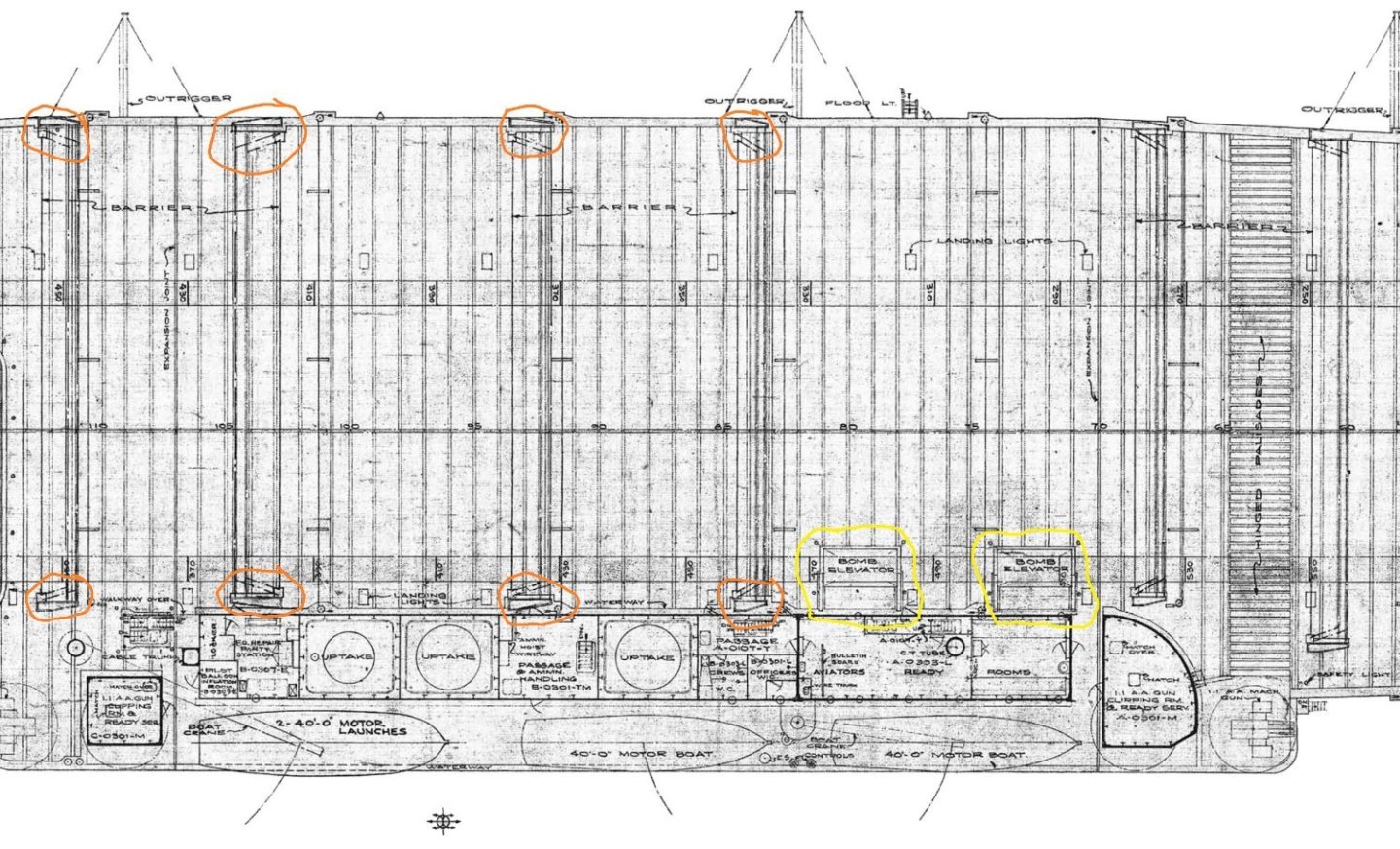
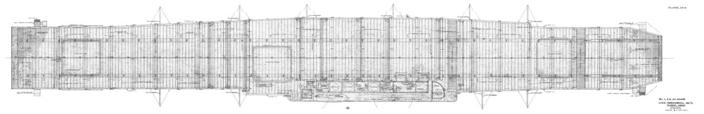
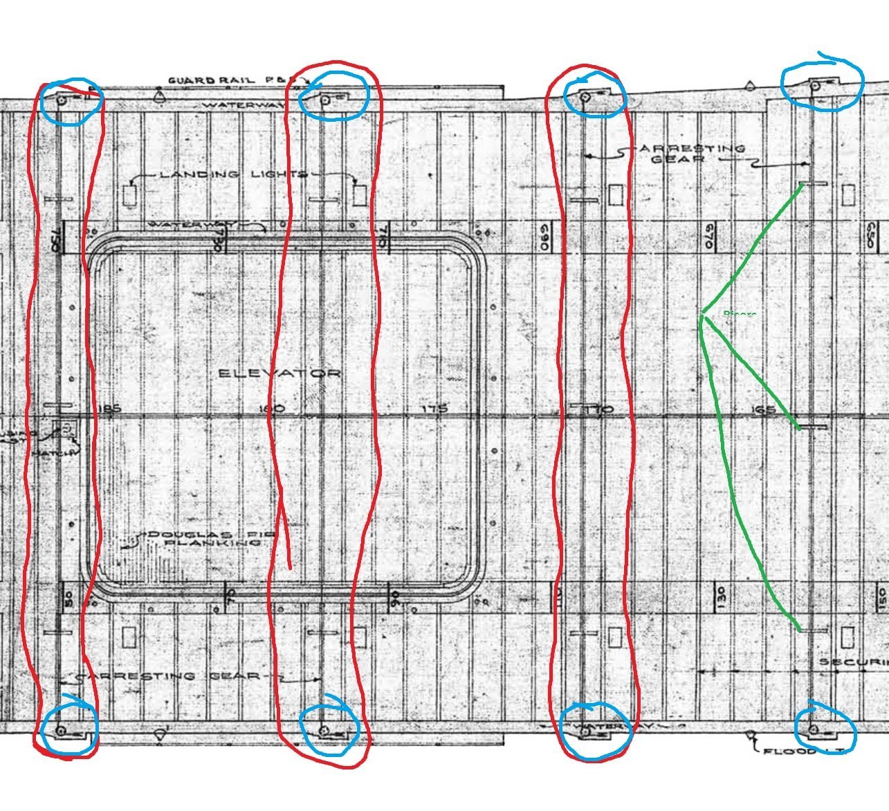
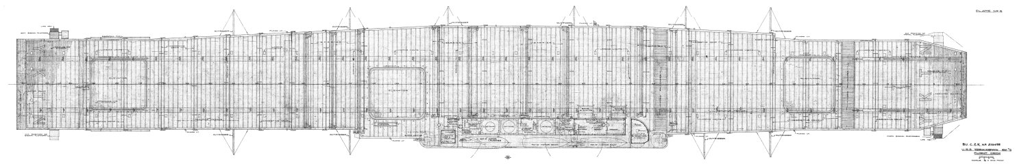
9 wires would be from almost at the stern to the midships elevator according to the sheet 6 flight deck plans.
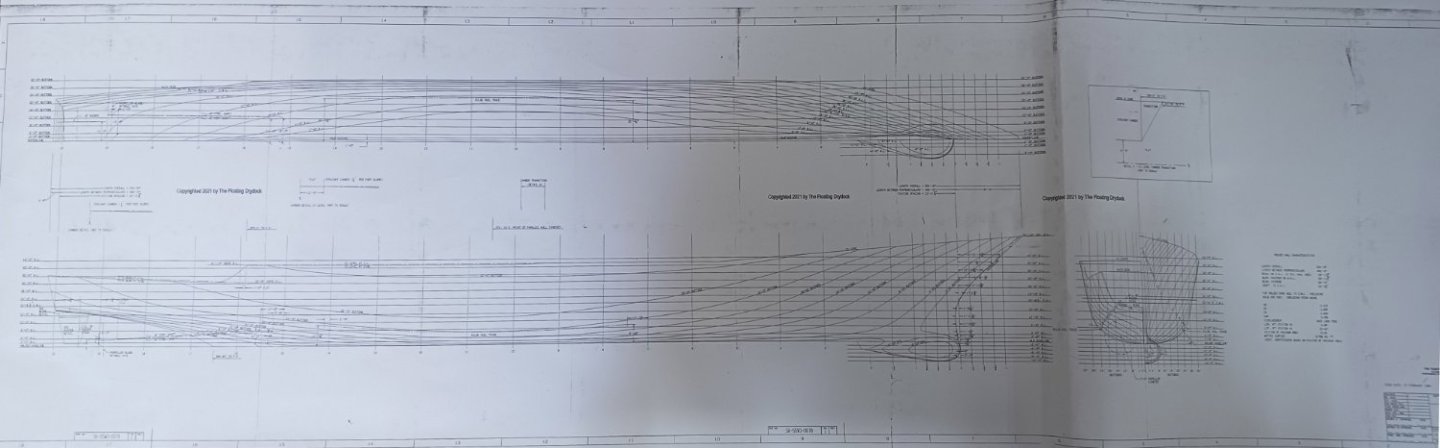
that is CV-14 USS Ticonderoga, an Essex class aircraft carrier, the successors to the previous Yorktown class that your model was part of. https://www.navsource.org/archives/02/14.htm
i have 6 sets of Booklet of General Plans of the angled deck Essex class saved on my computer
the plane guard was most likely a destroyer from 1 of about 5 different classes.
- Canute and Old Collingwood
-
2
-
-
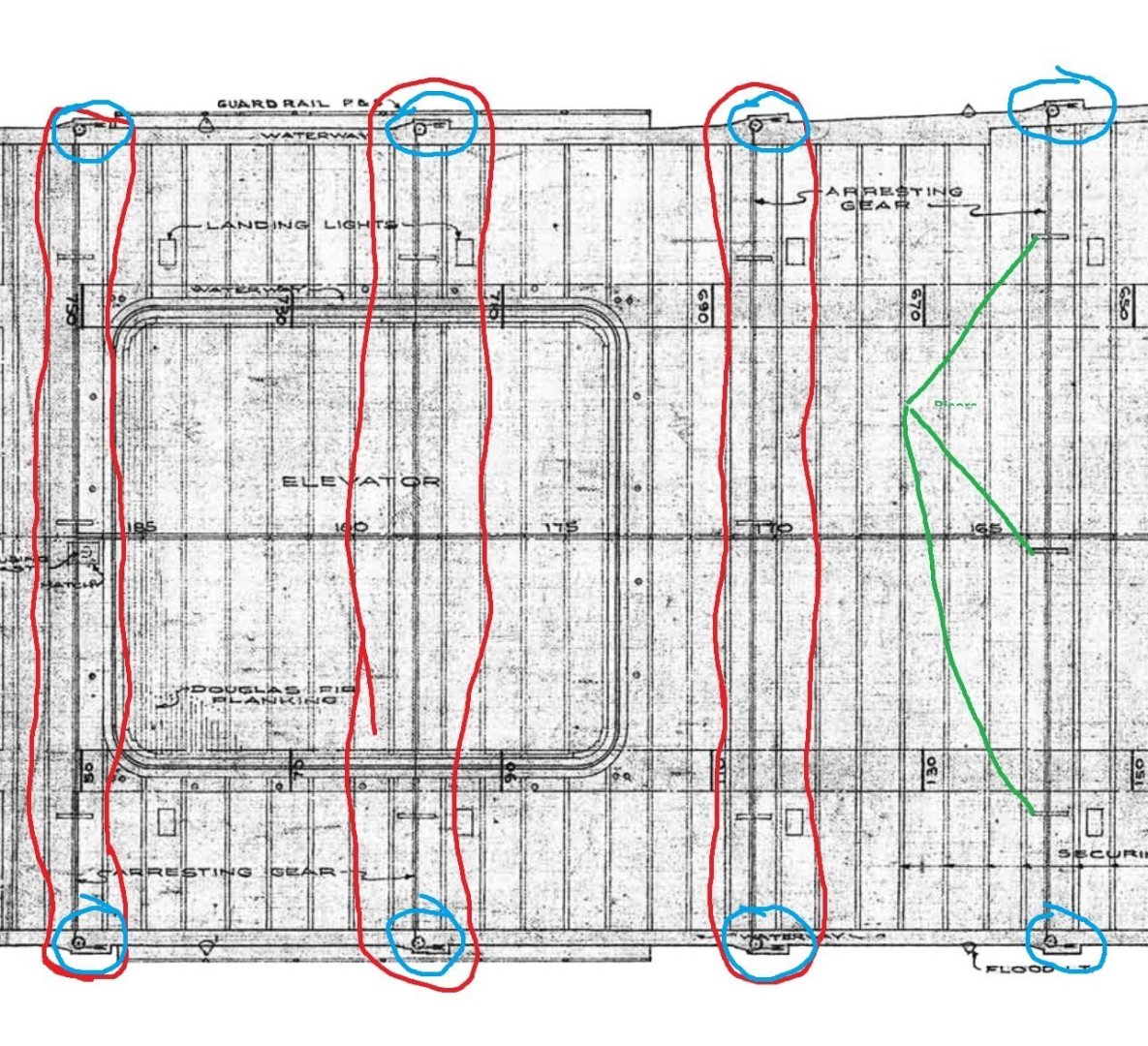
how many arresting wires come with the pe kit? here is a cropped picture of the flight deck with the red showing the arresting cable locations, the blue for the locations of the arresting cable pulleys & deck edge tabs the pulleys partly sit on then the green for some of the riser locations.
would not be Enterprise's sisters as both CV-5 Yorktown & CV-8 Hornet were sunk in 1942 & the Hellcats came out in 43 so he must of been on one of the Essex class carriers that started entering service in 1943.
- Old Collingwood, ted99, Canute and 1 other
-
4
-
you have them in the wrong spot as should be on the lines with the 3 short dashes as per Sheet 6 Flight Deck drawing.
as your friend was flying a F4F then he was on an escort carrier not a light or fleet carrier as they used hellcats & corsairs.
- Old Collingwood and Canute
-
2
-
not your fault the model & pe instructions appear to be crappy. there is a saying, "if in doubt, ask" before you make a mistake & we'll see if we can get the answer(s) so that you can continue building.
those line are crash barriers not arresting cables from midships elevator to alongside the island as i just checked the Booklet of General Plans of the Enterprise, 1944/45 Saratoga & 1946 Bunker Hill as the other plans of the fleet carriers i have are angle decks from 1955 to 1968.
your arresting cables stop before the midships elevator.
you have windows photo viewer as is part of windows which is what i use.
- Old Collingwood and Canute
-
2
-
are you using windows, mac os or linux? see if that pe is a bit longer then the dashes on the flight deck where the risers are supposed to be.
- Old Collingwood and Canute
-
2
-
-
did you look at sheet 6 flight deck of the plans i linked before as your wires are in the wrong places? do you see what looks like little dashes parallel to the centerline as there is supposed to be wire risers that the arresting cable lay on so that the cables are just above the flight deck to help the plane's hook catch the cable to stop the plane when landing.
-
-
i would leave applying the decals til last til at least all the large parts are glued onto the hull, putting done, most painting & touchups done plus less likely messing up the installed decals with model handling.
- mtaylor, Canute and Old Collingwood
-
3
-
take a look at this.
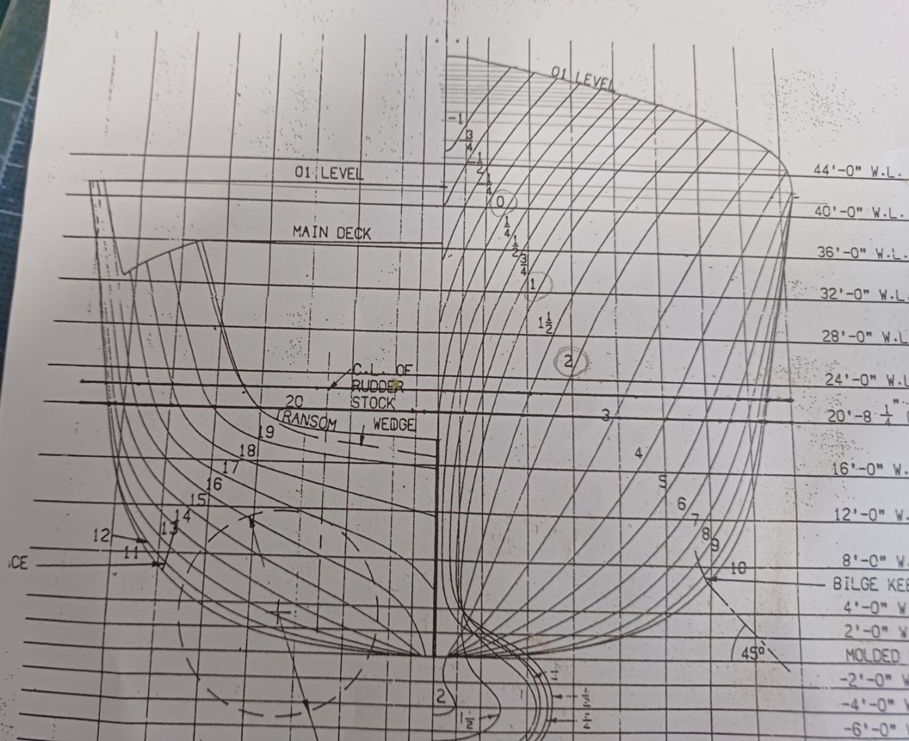
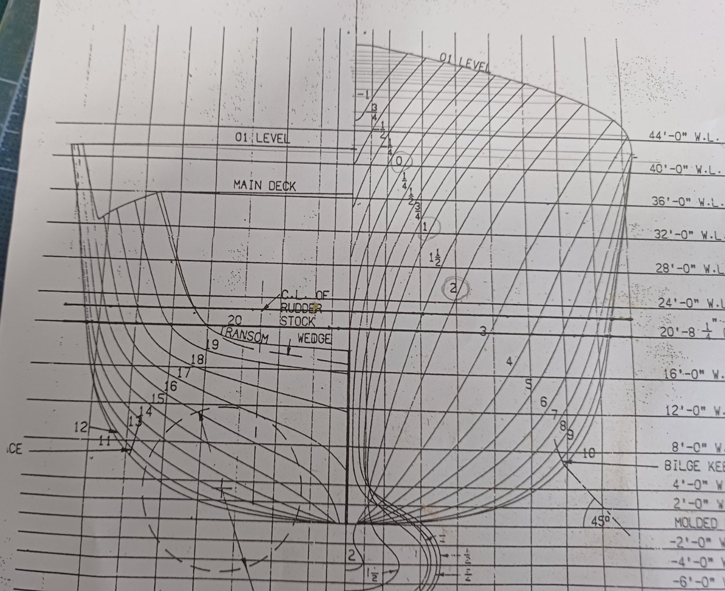
"In talking with Keith Bender (look for a build review of this model from Keith in early '24!) he noted that the rudders are molded too far apart. To quote Keith, "In reality, the rudders are 20' apart and the shafts are 26.26' feet apart. The manufacturer has molded the rudders 25 scale feet apart, and the shafts 32.66 scale feet apart". Keith followed up that statement by saying "I'm leaving them as is, because most people won't know or notice the difference". "
http://www.modelwarships.com/reviews/ships/ddg/ddg-54/ILoveKitCurtisWilbur/ILK62007.htm
-
-
-
by cutting along the top of the bulges where it joins the hull then pushing the bulges tops thru that hull slice to narrow the top(ledge) of the bulges. there is video(s) on the net about that. depending on the thickness of the plastic that forms the bulges & how much the tops(ledge) has to be narrowed to the proper width, i would shave/scrape/sand the sides of the bulges near the top of them to the proper width. but that is me as that is what i do.
BB-35 USS Texas Booklet of General Plans (1944) https://archive.org/details/bb35bogp1944v4/mode/2up
-
just to let you know on Trumpeter 1:350 USS Texas kit that the top of the torpedo bulges are too wide.
- Old Collingwood, ted99, mtaylor and 1 other
-
4
-
Chris, the true scale is 1/429 as per this link. http://www.shipmodels.info/mws_forum/viewtopic.php?f=84&t=286900
i'm using that same model 17 times to build all the USN OBB's during ww2 from the Wyoming class to Colorado class in this link. http://www.shipmodels.info/mws_forum/viewtopic.php?f=59&t=165105
-


USS Enterprise (CV-6) by ted99 - Trumpeter - 1:200 - PLASTIC
in - Kit build logs for subjects built from 1901 - Present Day
Posted
then you have to use Measure 11 March/April 1942 to Fall 1943 not Measure 21 Fall 1943 to Summer 1944. http://www.cv6.org/ship/camo-radar.htm
so you'll need Wildcats, Avengers & Dauntlesses for that group.