

ddp
-
Posts
81 -
Joined
-
Last visited
Content Type
Profiles
Forums
Gallery
Events
Posts posted by ddp
-
-
-
then also check for the stl files for the 20mm & quad 40mm boffers guns.
- SigEp Ziggy, robert952, mtaylor and 1 other
-
 4
4
-
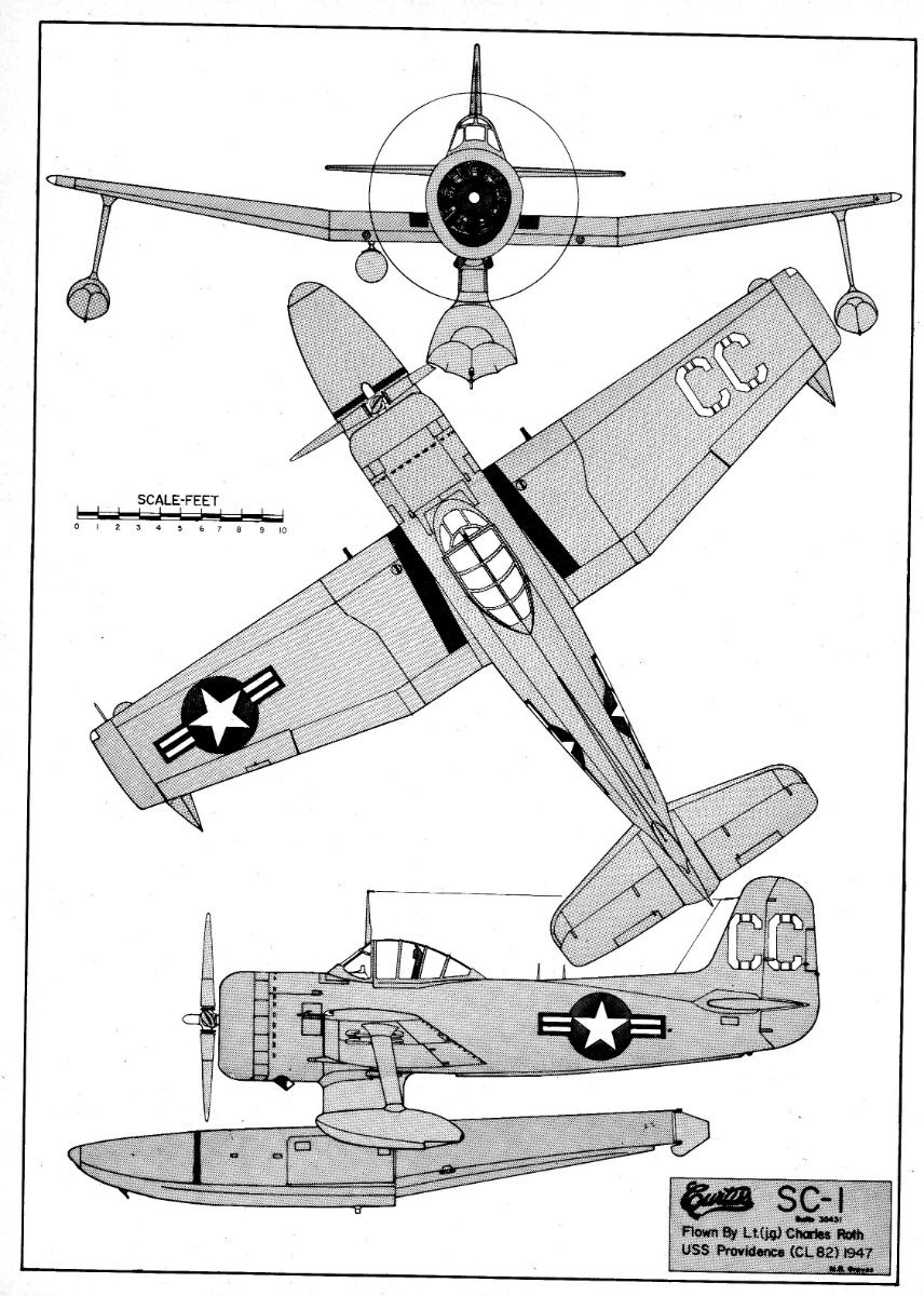
except that the ship's aircraft is a Curtiss SC-1 Seahawk-5 not a Hellcat.

- mtaylor, Canute and Bill Morrison
-
3
-
check these links for the quad 40mm mounts & 20mm guns.
https://www.3dmodelparts.com/1-500-quadruple-40-mm-bofors-autocannons-with-shields-4-pcs/
https://www.3dmodelparts.com/1-500-single-20-mm-oerlikon-cannons-pedestal-mount-16-pcs/
BB-63 USS Missouri Booklet of General Plans (1944) https://archive.org/details/bb63bogp1944
i would use an old #11 blade to scrape the hull down to the main deck. when i do mine eventually from the periods of 1944 to 1984, i'll be replacing the original main deck with .040" sheet plastic. i've done that in this link which is an ongoing project. http://www.shipmodels.info/mws_forum/viewtopic.php?f=59&t=165105
-
i use masking tape too as i hardly use clamps. take a look at this link as might come in handy even tho for 1940 Yorktown.
CV-5 USS Yorktown Booklet of General Plans (1940) https://archive.org/details/cv5bogp1940
- ted99, mtaylor, Old Collingwood and 1 other
-
4
-
the twin barrel 20mm gun mount has the magazine on both sides. http://archive.hnsa.org/doc/guncat/cat-0014.htm
-
are you certain the ammo drum is on the left side of the gun & not the right side?
http://archive.hnsa.org/doc/guncat/cat-0004.htm
http://archive.hnsa.org/doc/guncat/cat-0006.htm
http://archive.hnsa.org/doc/guncat/cat-0008.htm
-
-
-
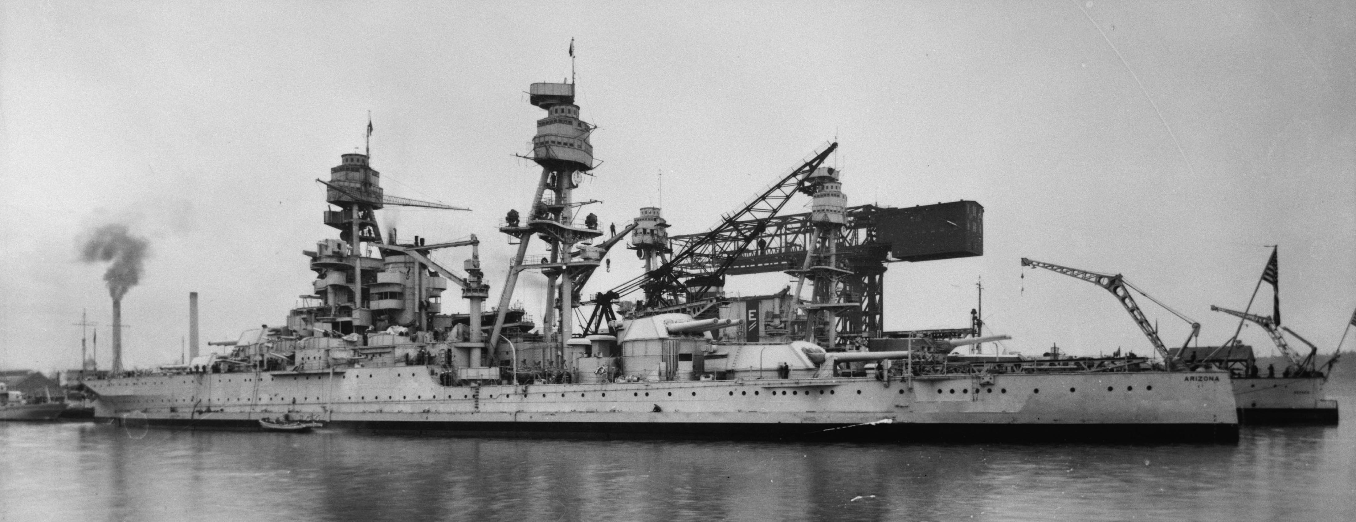
Egilman, i presume you have never attempted to correct that 1/429 scale Arizona concave stern. take a look at this link.
http://www.shipmodels.info/mws_forum/viewtopic.php?f=59&t=165105
take a look at this link about the correct scale for that Revell USS Arizona.
http://www.shipmodels.info/mws_forum/viewtopic.php?f=84&t=286900
-
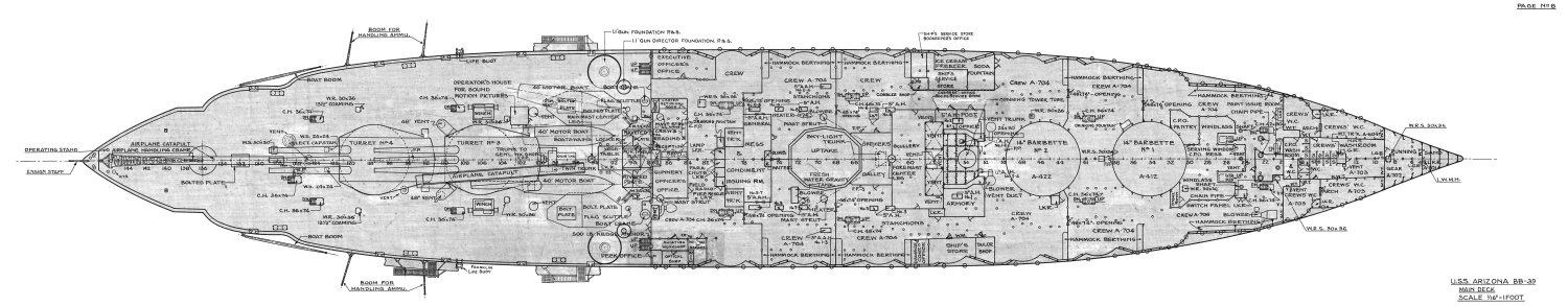
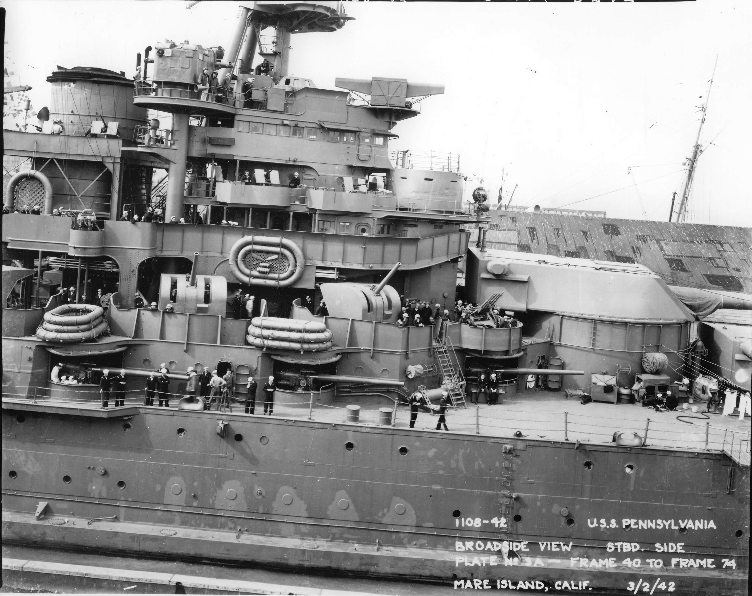
hopefully you did not glue down the 5" 51cal gun mounts yet as that cylinder shaped shield that the gun barrels are sticking out of is for weather protection as they are made from canvas & rolled up for action or warm weather. look at attached links.
http://navsource.org/archives/01/038/013803c.jpg
http://navsource.org/archives/01/039/013954.jpg
http://www.navsource.org/archives/01/013921a.jpg
when the weather shield is lowered to cover the gun mount openings, 5" guns #1 - #6 are pointed to the bow & 5" guns #7 - #10 are pointed to the stern.

-
Dave, don't know if you know about this site about your ship. http://www.mustangone.com/putnam/
is this the set of plans you are using? DD-692 USS Allen M. Sumner Booklet of General Plans 1968
what are you using to get the sonar dimensions from?
-
Massimodels, what part of Toronto as i use to live in the Bathurst & Steeles area for a couple of years in the mid 90's?
- mtaylor and Keith Black
-
2
-
-
Joe, where were they located on Adm. Scheer, in the bow or on the lower hull sides?
"SONAR and hydrophones are seperate technologies. The former is an active detection system using high frequency sound, the other is a passive listening device with directional capabilities. Hydrophones were developed in WW1 and SONAR came along in the interwar years. By the 1930s Germany had its own version of SONAR, called an S-Geraet, which was developed independently of British SONAR (ASDIC) research. The German GHG hyrophone arrays were highly developed and efficient, but like all hyrophones, was effected by sea state and ship speed. To the best of my knowledge, only escort vessels had the S-Geraet, although it appears that most large surface ships in the KM had the GHG as a passive early warning system."
-
i don't see any sonar ports in the bulbous bow in this link. https://www.alamy.com/stock-photo-launching-of-the-battleship-bismarck-in-hamburg-1939-37005865.html?imageid=6980C079-3173-4F05-ADDA-EB82E5E33A88&p=291611&pn=1&searchId=6e2d733b32b38bc8390c317c0395e4c5&searchtype=0
read this link as ship supposedly did not have active sonar. http://www.kbismarck.org/forum/viewtopic.php?t=140
-
-
-
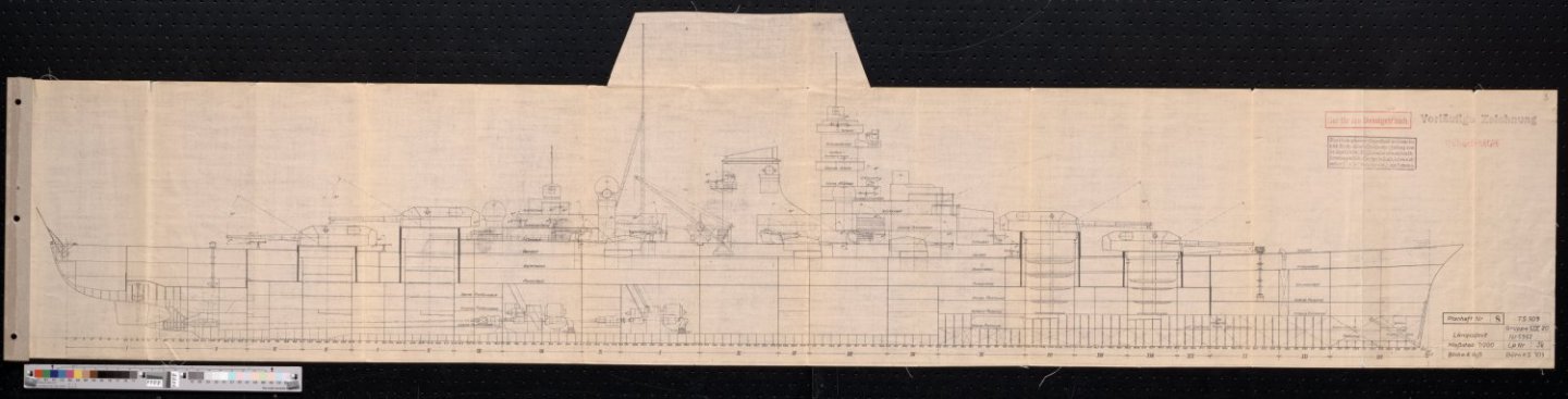
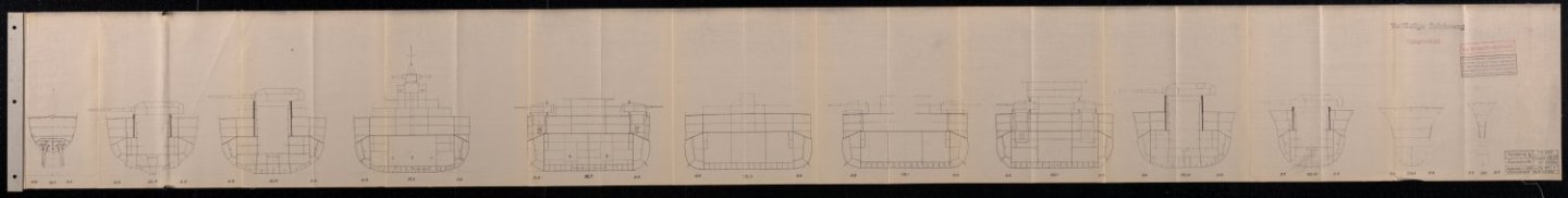
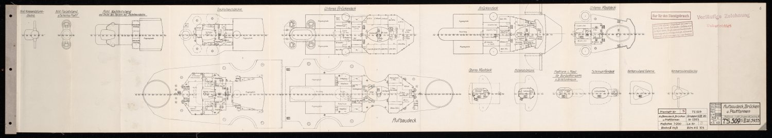
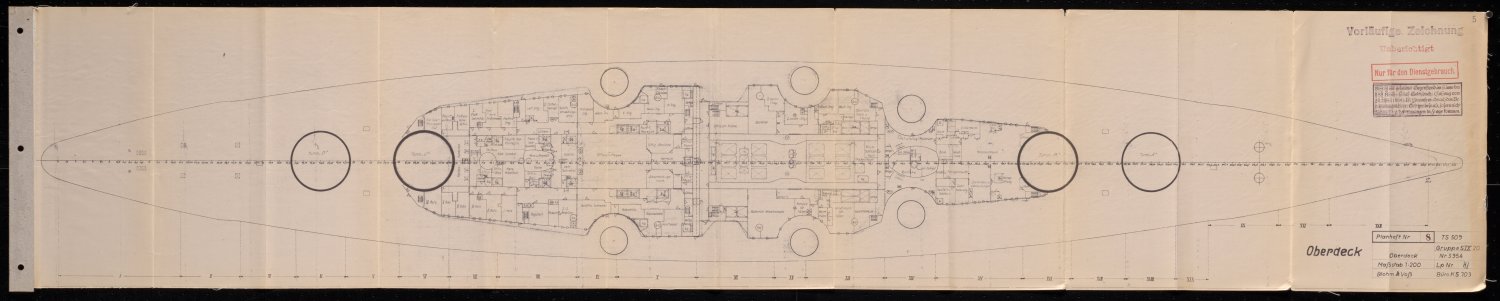
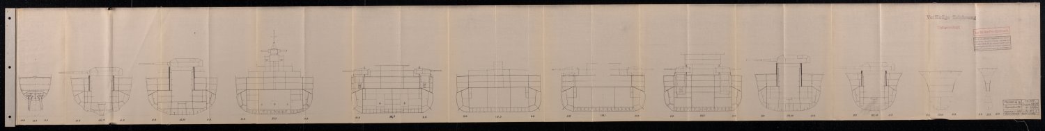
it appears to supposed to have a sheer at both ends according to this 1st drawing. also link to download complete set of plans. https://archive.org/details/yn509bogp193x
-
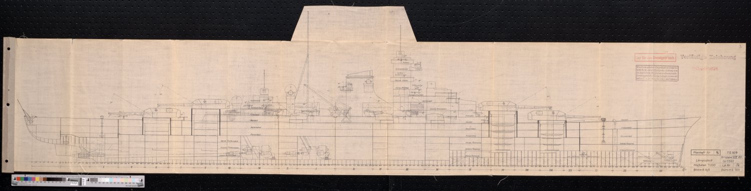
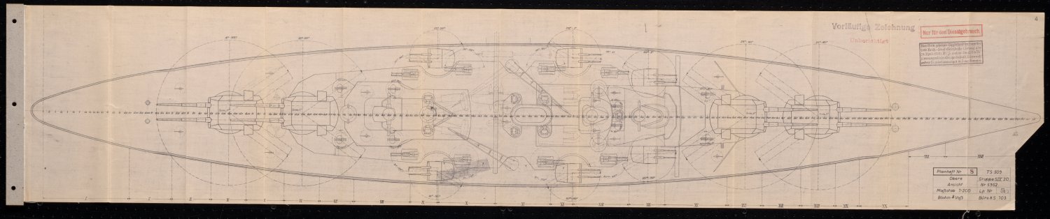
Keith, you are wrong as that is the Bismarck as i just finished looking at the plans that are in German.
Lillypawz, the set of plans just under the S.S. Noggsund is that of a WW2 Town class light cruiser of the British Royal Navy. thought it was of a Modified Leander class light cruiser til i saw the triple barrel 6" gun turrets, the Modified Leander class had 2 barrel gun turrets.
-
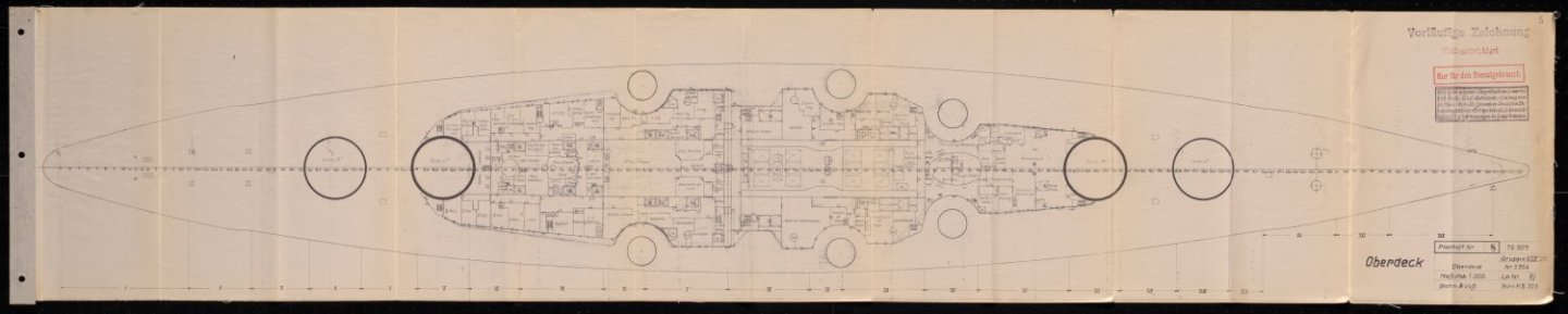
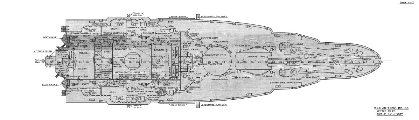
did you use crazy glue to glue the catapult to the turret roof? the guns for the empty tubs where to be installed sometime in the 1st half of 1942 if the war with Japan did not breakout. that thing, is that the chair locker as shown on the main deck drawing i posted that sits partly under the rear overhang of #3 14" turret between the 2 40' motor boats? do a comparison for the empty gun tubs height of your model with that with the navsource jpg link i had posted above.
Booklet of General Plans 1941 http://navsource.org/archives/01/pdf/013939p.pdf
-
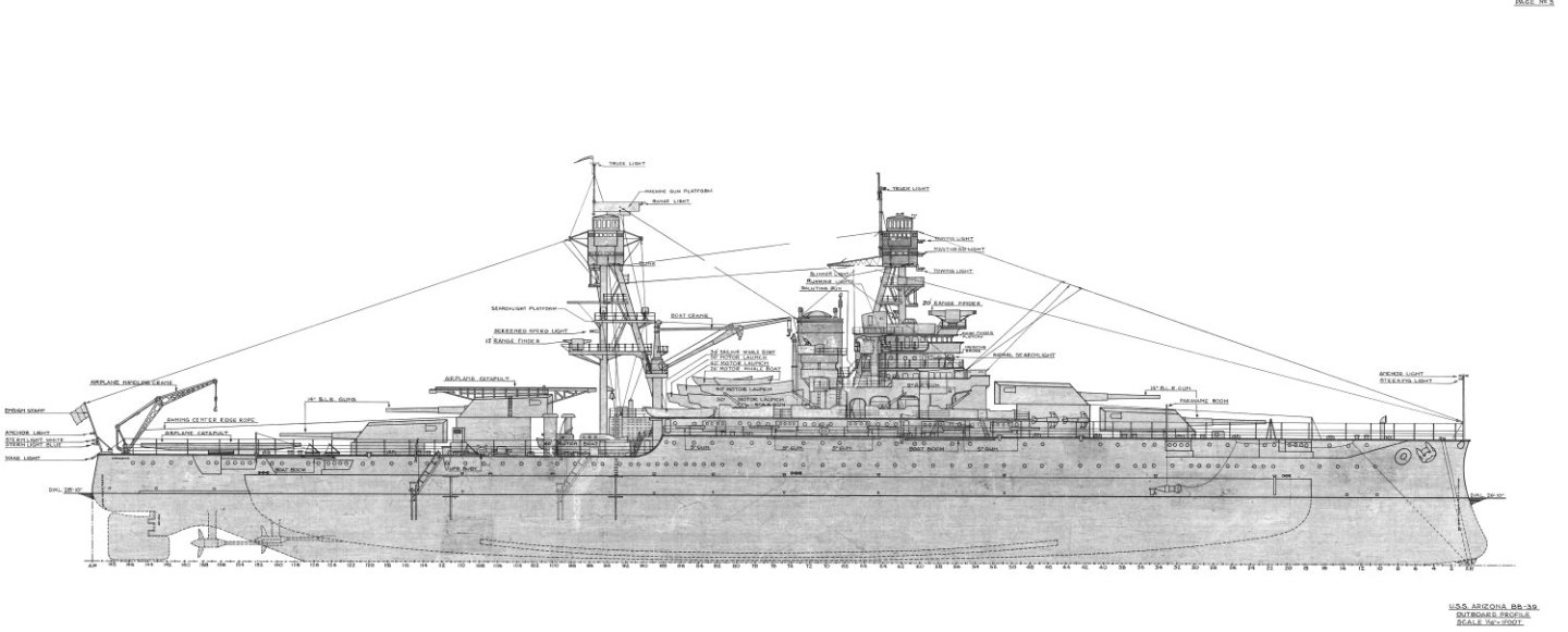
Rob, the catapult on turret 3, is it glued in place or just sitting there as it is supposed more angled then what you currently have it? look at the main deck drawing i've posted. the tubs for the quad 1.1" guns on the main deck are supposed to be raised not sitting directly on the deck & same for the quad 1.1" director tubs. look at the outboard profile drawing i've posted & the link. what is that thing that will be standing between the front 2 legs of the main mast on the upper deck as not shown in the link or plans? http://www.navsource.org/archives/01/013921a.jpg
http://www.navsource.org/archives/01/39a.htm

- Old Collingwood, mtaylor, Canute and 2 others
-
5
-
-
it is 4 files at about 6mb, will send it to you via email like i did with the Bonnie.
- Canute, NavyShooter and mtaylor
-
3


USS Enterprise (CV-6) by ted99 - Trumpeter - 1:200 - PLASTIC
in - Kit build logs for subjects built from 1901 - Present Day
Posted
Roger, Panama lock dimensions hardly influenced the design of these fleet carriers as it was the Washington Naval Treaty that influenced those ships. that treaty only allowed 135,000 tons to the USN for aircraft carrier builds so out of that limit deduct 72,000 standard tons(Navsource) total for the Lexington class aircraft carriers which leaves 63,000 tons which was used on the next 4 aircraft carriers not including CV-8 USS Hornet.
https://en.wikipedia.org/wiki/Washington_Naval_Treaty
https://www.navsource.org/archives/02idx.htm
the reason the Hornet was built to the mostly Yorktown class specs as it was faster to use that class drawings then to wait for the Essex drawings to be finished & start building to those specs.