

ddp
-
Posts
197 -
Joined
-
Last visited
Content Type
Profiles
Forums
Gallery
Events
Posts posted by ddp
-
-
same to you & happy new year.
- Canute, Old Collingwood, Boeing774 and 1 other
-
 4
4
-
look at your model's 20mm ammo magazine with the 1 in this picture. http://www.navweaps.com/Weapons/WNUS_2cm-70_mk234_Iowa_pic.jpg
you might want to thicken those magazines.
- Canute and Old Collingwood
-
2
-
did you show the corrections to your friend that you did to your model that he did not do to his?
i have 5 of Revell's 1/480 scale Yorktown kits either built or in the stash with 1 of the stash being the Hornet with the Mitchell bombers. the intention is to build the 3 Yorktowns at different stages of the war with the Yorktown at the begining of the war, Hornet during the Doolittle raid & the Enterprise at the end of the war so that the differences between all 3 can be seen. the other 2 kits will be kitbashed into the Ranger & the Wasp like i am doing kitbashing Revell's 1/429 scale USS Arizona into to 16 old battleships of ww2 & an extra Mississippi as a gun missile training ship after the war.
-
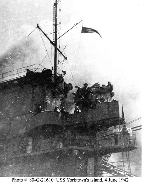
the model's crossbar seems to be wider then in relation to the 1 in the photo on the ship. is the height of the mast from base to crossbar the correct scale height because if it is then it can be used to calculate the correct width of the crossbar?
-
Haze Gray, i have the drawings of BOUVET 1896 17.4mb , JAUREGUIBERRY 1893 16.5mb & MASSENA 1898 6.41mb saved on my computer from the French naval site years ago before that site got hacked & shutdown so if you need a copy, let me know.
BOGP's PG45 USS Panay 1928 (Yangtze River Gunboat, reclassified PR‑5 '28)
-
wrong shape as looks like it should be a 4 point diamond as in baseball with home & second base the verticals & 1st & 3rd the horizontal bar as that is what it looks like in your previous picture. what are you going to use for the angled supports as thinner then the horizontal bar which is thinner then the main vertical post?
- Canute and Old Collingwood
-
2
-
-
are you talking about the one that you posted a picture of at the top of pg 5 or on the island?
- Spaceman Spiff and Canute
-
2
-
no problem. thought it might come in handy for you when i saw it so linked it for you to watch.
- mtaylor, Spaceman Spiff and Canute
-
3
-
-
what are the 4 notches on the 2 edges of the elevator in the middle picture for?
- Keith Black, Canute and mtaylor
-
3
-
depends on the time period so sometimes there is a shadow & sometimes there is no shadow line.
- Canute and Spaceman Spiff
-
2
-
-
-
what mark are those Veteran 3"50 cal gun mounts as the Iwo Jima class used mk35 gun mounts? Black Cat Models does make mk33 gun mounts.
https://blackcatmodels.eu/en/weapons/292-mk33-3-automatic-twin-gun-x2.html
-
go thru this link at comparable ship for the time period you are working on for the flight deck markings.
-
-
i have 4 of them built out of the box back in the 70's that i'm going to redo in various configurations from ww 2 to the gulf war. take a look at this link.
https://archive.org/details/ship-design-drawings?tab=collection&query=uss+missouri
- Canute and Old Collingwood
-
2
-
mounted onto the front of the mk 33 directors til the directors were replaced with the mk 37 with the radar mounted on the top.
your Missouri, ww2, Korean war or gulf war configuration?
- Canute and Old Collingwood
-
2
-
would be kind of hard to put a radar on the top of the director when it had a canvas cover for that area. most radars for that type of director had them mounted on the front face. have a look at this link that shows the aft director without radar in which you can see a crew member sticking out of the open top, back right corner. https://www.navsource.org/archives/02/020526c.jpg
- Canute and Old Collingwood
-
2
-
-
look at the drawing i had posted, bottom row, 2nd from the left. also look at this link/picture.
-
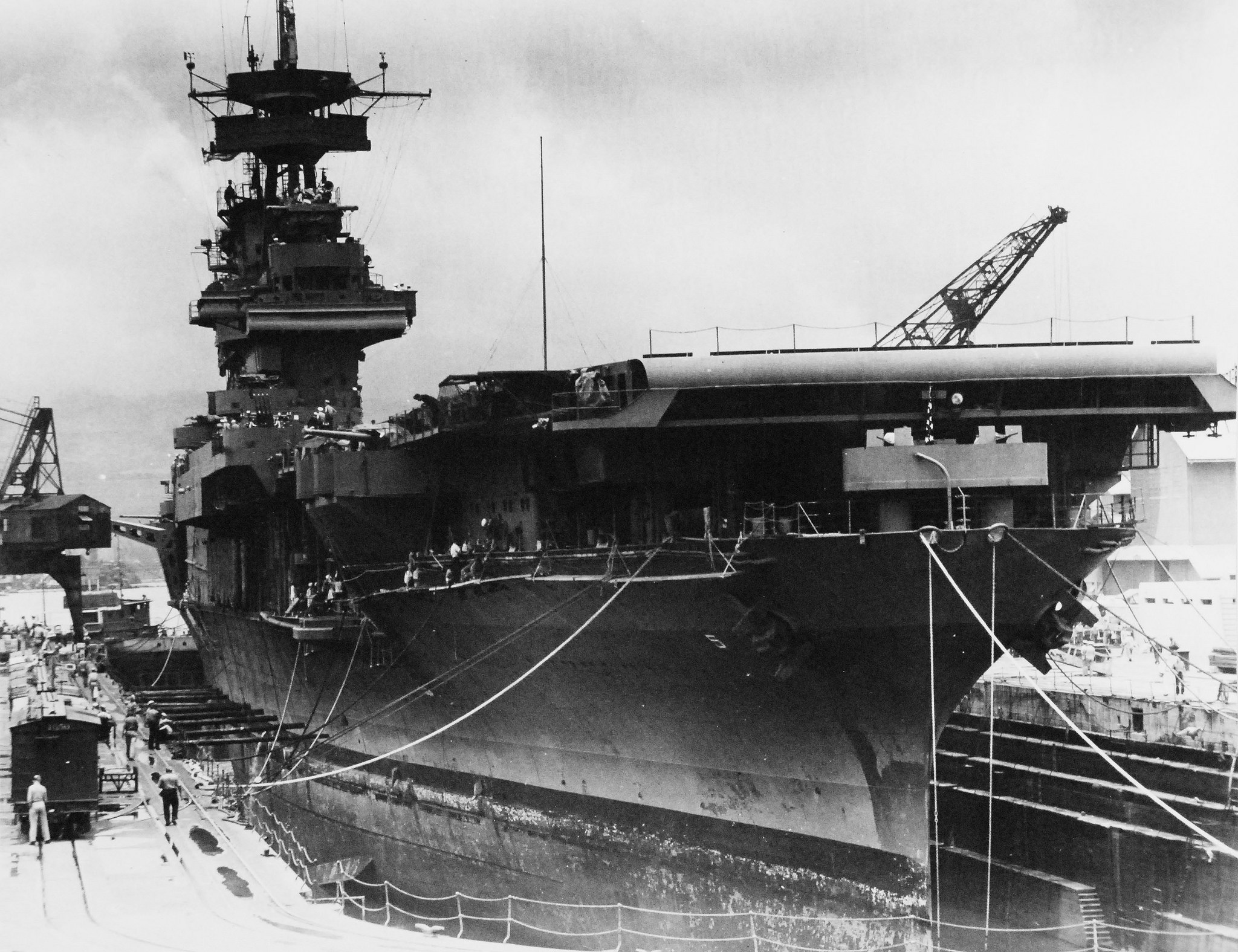
the 2 mk 33 directors are in reverse & unlikely those directors had radar dishes on them as Enterprise did not get hers til late 1942-43. Battle of Midway photos do not show any radar on those 2 locations. the platforms with the 2 search lights each should be centered on the center funnel uptake not offset like you have it now.
https://www.navsource.org/archives/02/05.htm
-
so your model will show 2 enclosed 3" gun mounts in front of the island & 2 open 3" gun mounts on sponsons on either side of the stern, correct?
- Canute and Spaceman Spiff
-
2

HMS Lion by Ian_Grant - 1/150 - RADIO - RESTORATION - WW1 Battlecruiser
in - Build logs for subjects built 1901 - Present Day
Posted
your decking pattern appears to be the same as done on 3d printed warships which i think is wrong. border planking would be done 1st around structures & hull edges then the 1st planking would be laid on the centerline then infilled on either side of the centerline so will have staggered butt joints not what you have done.