g8rfan
-
Posts
182 -
Joined
-
Last visited
Content Type
Profiles
Forums
Gallery
Events
Everything posted by g8rfan
-
Nice results. What brand of tinning solution did you use?
-
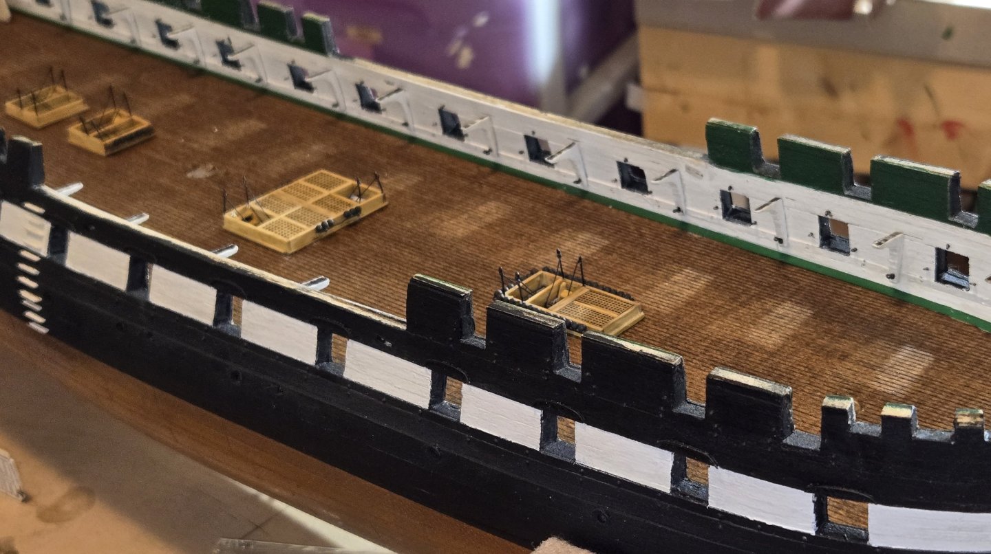
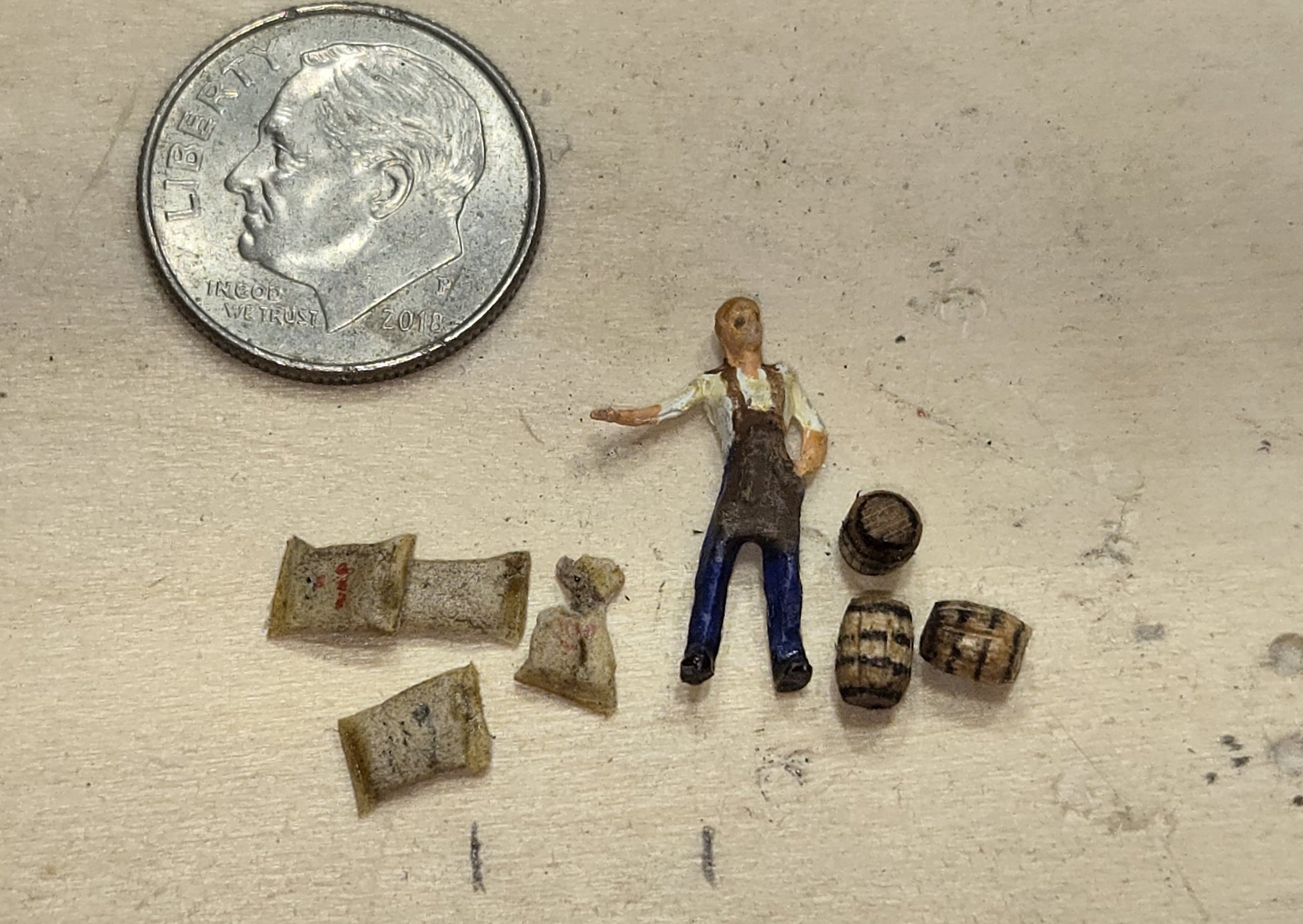
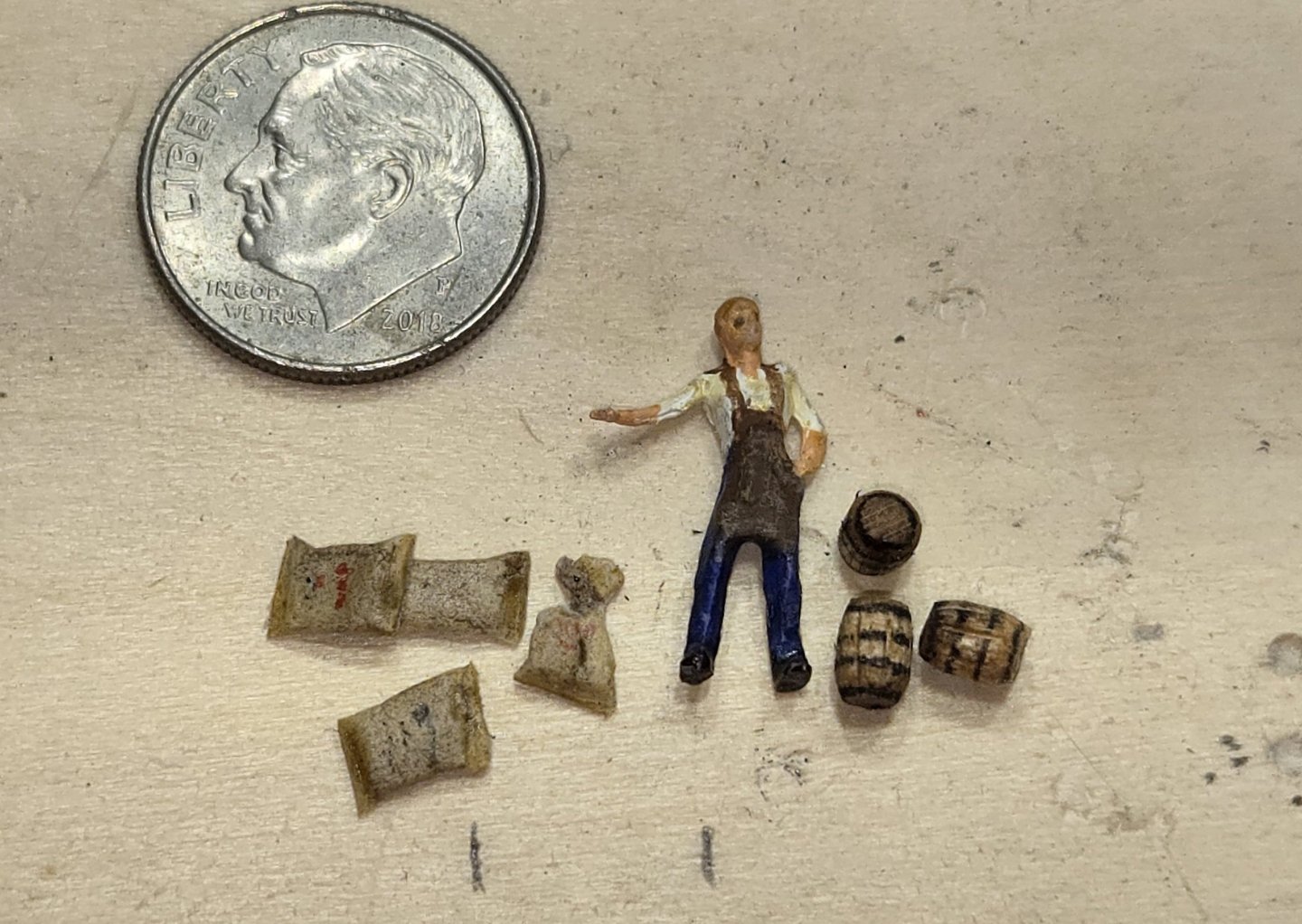
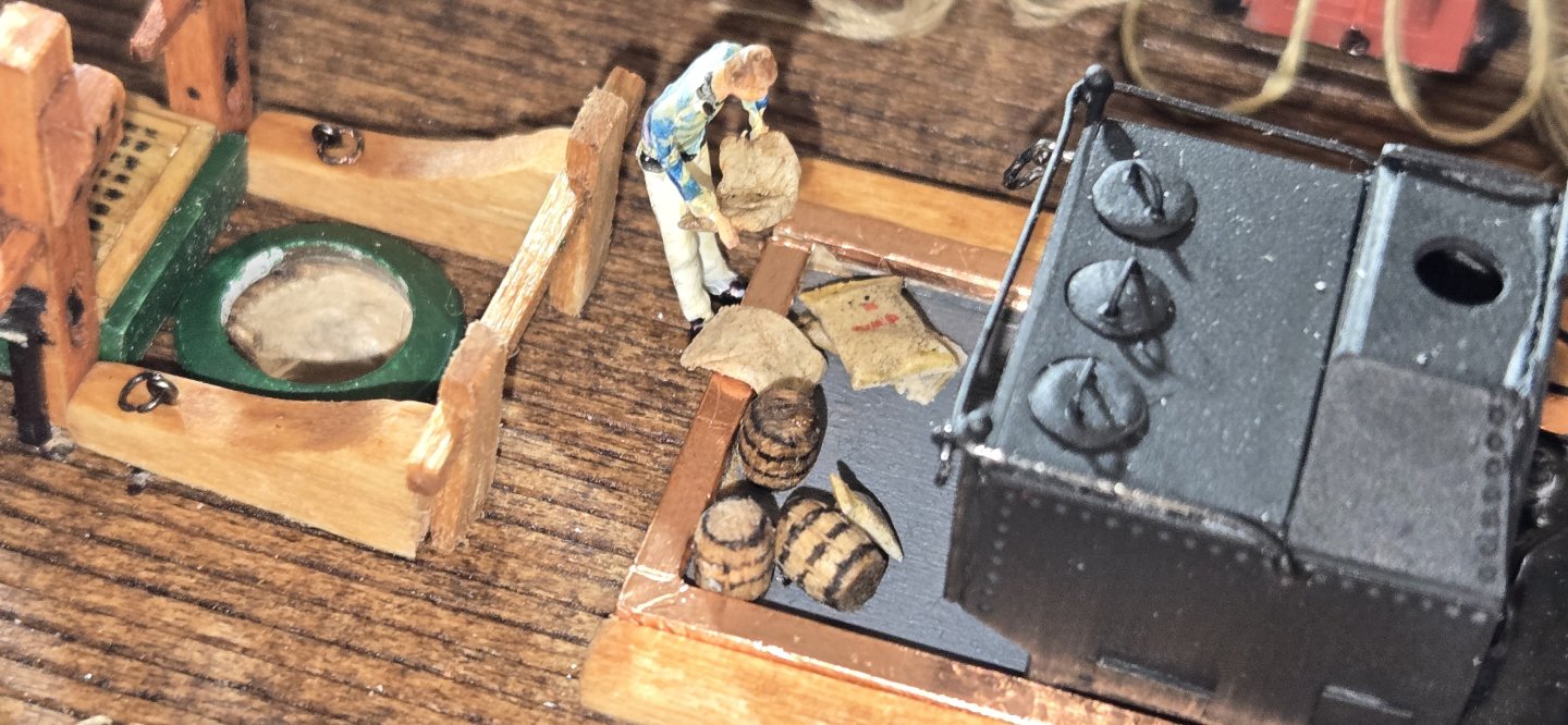
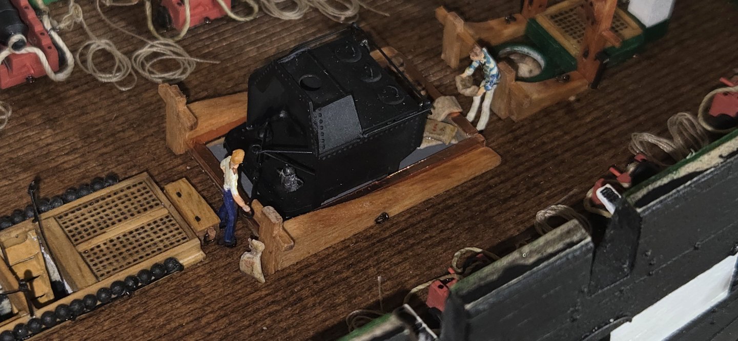
Thanks Mustafa, glad you liked them, and yes, we are all very fortunate to have the real ship to look at and even more so now that the internet allows us to see it from lots of different perspectives without actually being there. With the galley and everything in place, I decided to add a few more totally unnecessary details. From the beginning, I planned on having a good number of crew on the model. Naturally the galley is a good place to start. I made up a few small barrels, some burlap sacks (flour, beans, etc) and of course a cook. I also made up the chest that sits just in front of the camboose

-
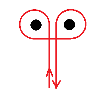
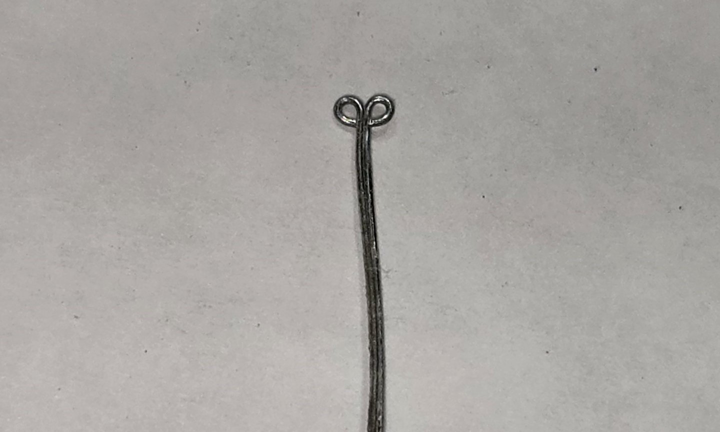
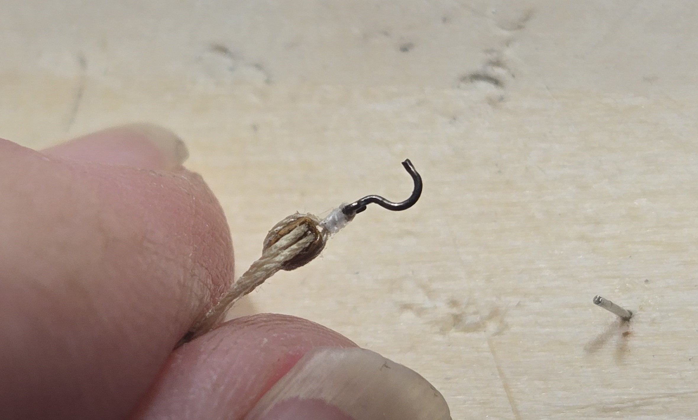
Welcome to the group Cena. You're going to find this is a great sight with lots of talented and knowledgeable folks ,more than willing to help. This ship is definitely a challenge, but you can certainly do it. Just keep moving even a little at a time. Regarding the pics, when you click "choose files" at the bottom of the post it will upload the file, then when you click "done" it will insert the file where ever the cursor is. If you decide to insert a photo after writing a bunch of text, just place the cursor where you want it before clicking "done". I noticed in your Emac that you were thinking of making eyeballs. Good idea, as the ones supplied in the kit are very bulky. At our scale, making them is not easy. I found that cutting the eye off a fish hook is the easiest thing. You want to use fly hooks, which are very tiny, size 16-24 (bigger number=smaller hook). You can get a pack of 50 from Temu pretty cheap. Also a good place to buy copper tape in various widths down to a couple millimeter. Good luck, looking forward to seeing your build.
- 4 replies
-
- 1
-

-
- constitution
- revell
- (and 1 more)
-
Thanks alot Gregg, I really do appreciate the support and glad to know that I can actually help someone out.
-
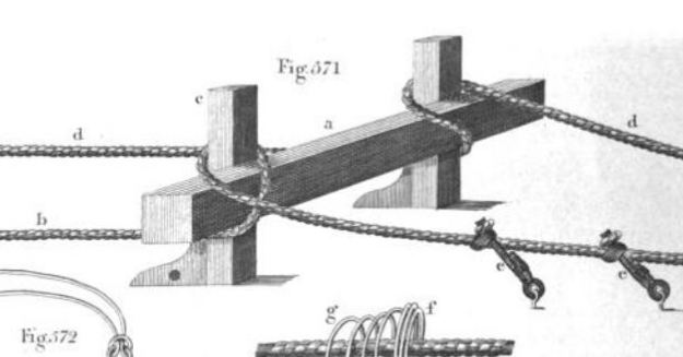
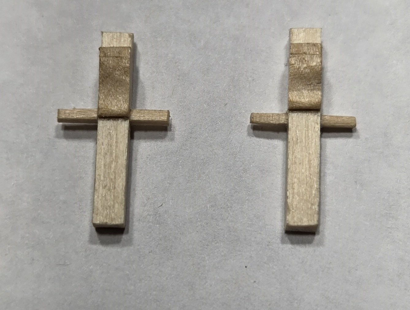
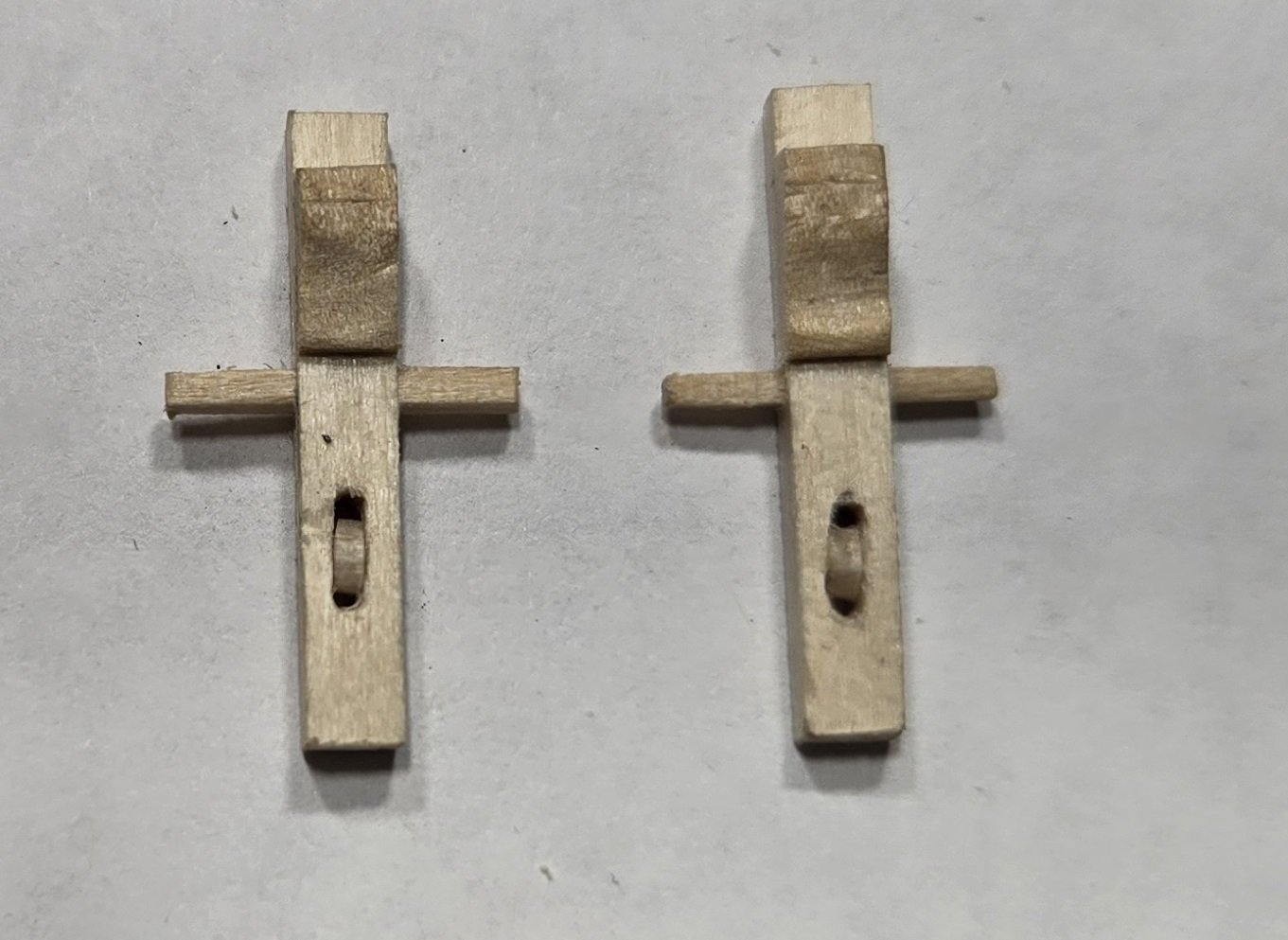
After failing to find any additional info one rider bitts, I decided to go with the wooden cross style bitts I mentioned above. In trying to establish exactly where the riders would be positioned on the deck, I first was looking at Lord's deck plans from 1927. I have this printed and hanging on the wall, covering the gun deck plan provided by BJ. I had gotten out of the habit of looking at the BJ plans, mostly relying on Lord's, but for what ever reason, I took a look at the BJ plan and wouldn't you know it, they show the wooden cross style bitts. I guess I should pay more attention to the plans supplied in the kit. I will say, it would be nice if the instructions didn't just say "the anchor chain cables and large iron bitts currently on the Constitution date from a later period", but would go on to say that these bitts were constructed of wood "as shown on the gundeck plan". Better yet, have an actual illustration of what they looked like and perhaps some dimensions. In any event, it confirmed that this is what should be in place. As I made my measurements to see where these would be placed on the deck, I quickly realized that the "pan" for the camboose was too wide. The aft riders are right next to the camboose, and with it as wide as it was, the riders would also be too far outward. Fortunately, I had not yet glued this assembly down on the deck. The camboose was easily separated from the pan, which I then modified to fit the camboose tightly instead of having a gap on either side. The riders were made from 1/8x1/4 stock. The plans indicate that the forward rider extended the length of the scuttle, but on the current ship, it stops just in front of the scuttle. I chose to make mine so it stopped in front. The aft riders are just slightly longer than the pan for the camboose. On the plans, both of these bitts show the cross piece extending from one post to the other. Hoever, if I did this on the aft rider bitts it would be right in front of the camboose "oven" area and I didn't think that would be very practial. So the aft bitts I made as crosses and the forward bitts are all the way across. here they are with stain and ring bolts in place


-
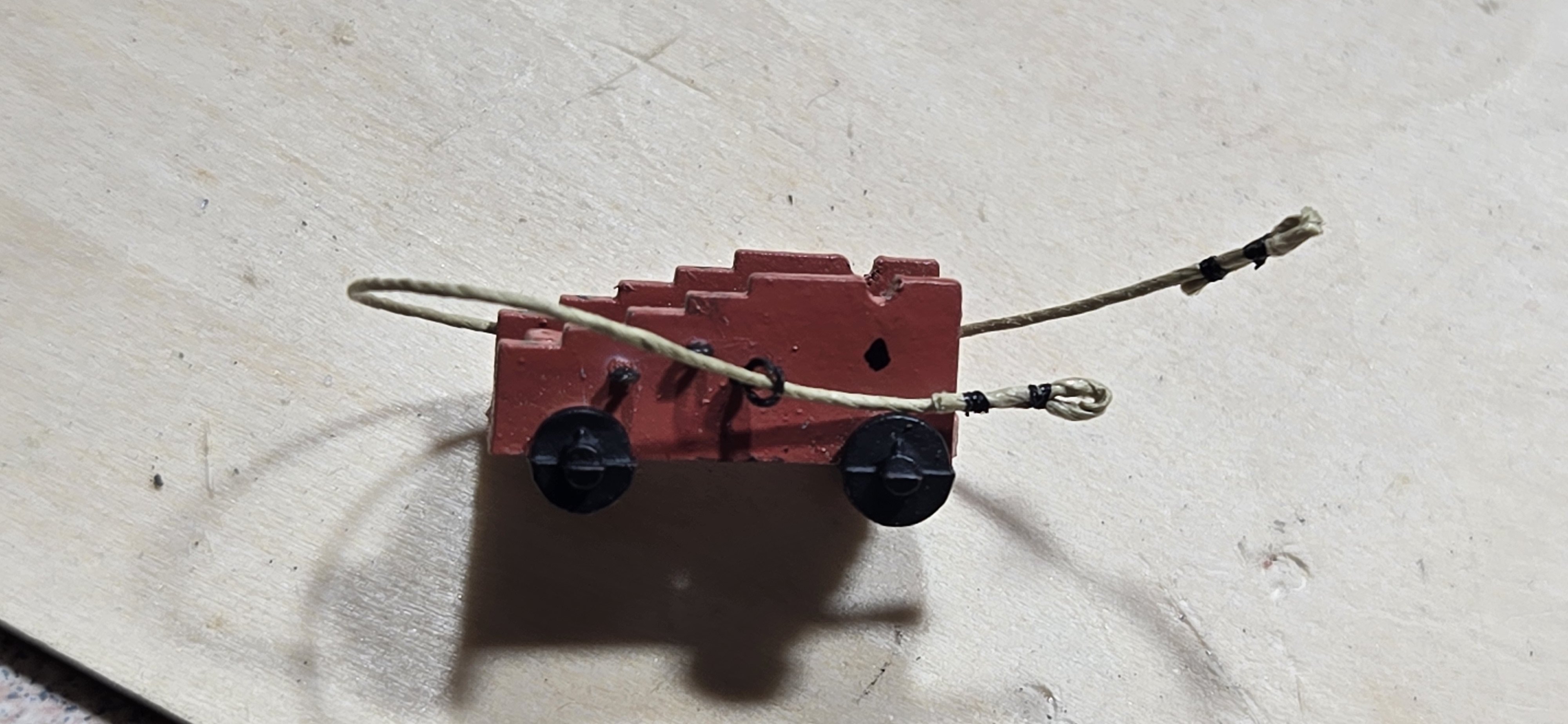
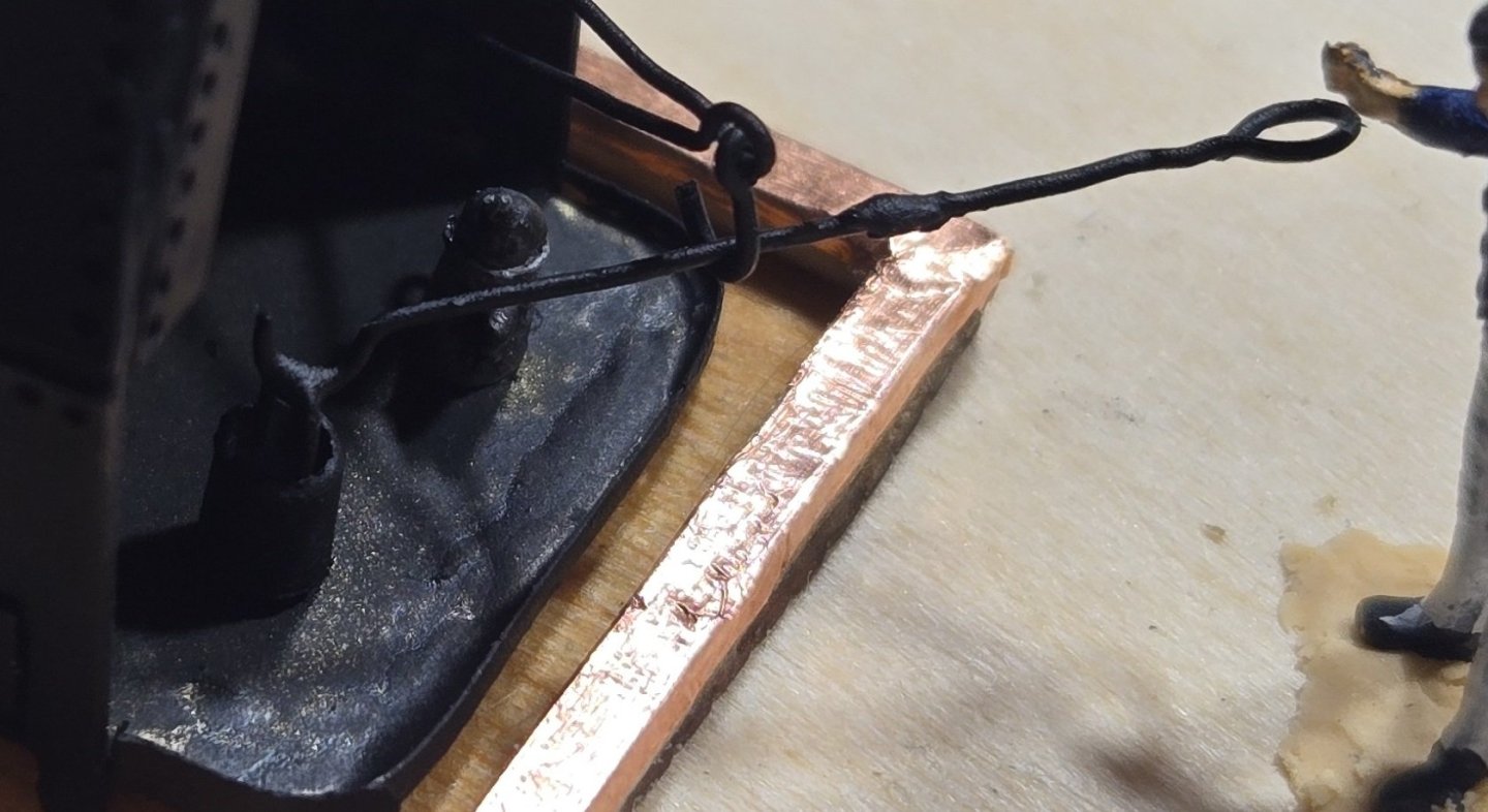
Moving right along, I decided that even though the ship did not use chains at this time, there must have been some sort of cable stop in the manger. I could not find anything to support that, but it seemed logical and it's a nice feature. I modeled the stopper after the one currently on the ship and again used known dimensions of surrounding items to determine the dimensions of the stopper. It was actually a complex little assembly. Everything was made from wood except the crossbar, which is 24 ga wire. The little balls on the end of the crossbar were made from epoxy putty The stoppers on the ship currently do not have anything on the outsides, however, the messenger cable has to run around these and so there must have been something there for the cable to ride along. I decided to put rollers similar to those on the side of the anchor bitts. These were made from styrene. The notch in the front of the base is there to fit over the top of the manger rail. In addition to these, there is also the stopper bill pulley for the messenger cable. The timbers this pulley rests on were of course wod. The pulley and the bracket to hold it were cut from flat stock styrene. Sorry for the dark photo. That was about it for the manger area


-
Hey Peter I have been quietly following along with your build, but after reading the comment by Bitter end, I just had to reiterate. It truly is amazing what you have done with bare wood. Your precision and craftsmanship are superb. Fine job!
-
I forgot to mention the other text references provided by the Navy Historical Command. They were HMS Victory: Her Construction, Career and Restoration – Alan McGowan (Naval Institute Press, 1999) Seamanship in the Age of Sail – John Harland (Naval Institute Press She said the second one should be particularly useful and contained alot of illustrations. Unfortunately, neither of these is available online and the ones I have found for sale are a bit pricey. If anyone out there has this book I would be interested to hear what it has to say about the anchor bitts.
-
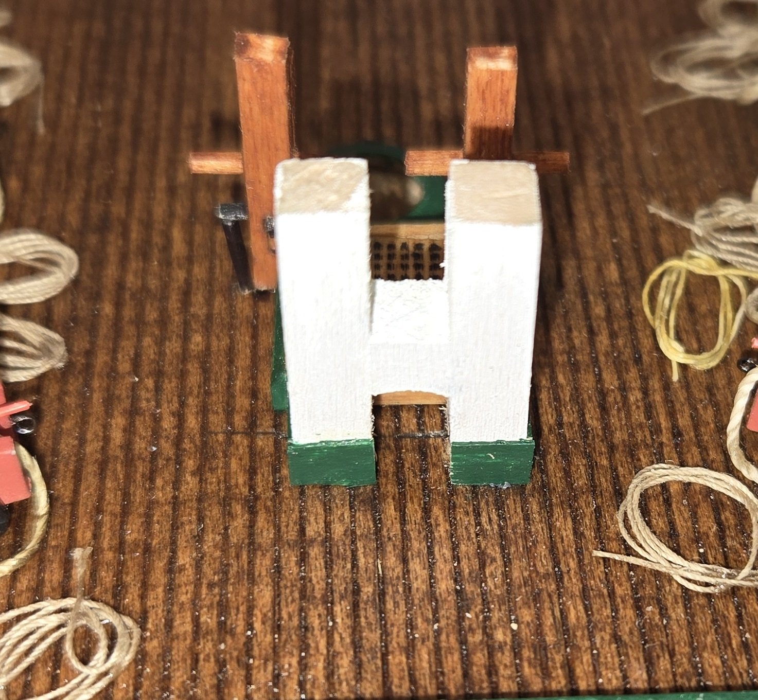
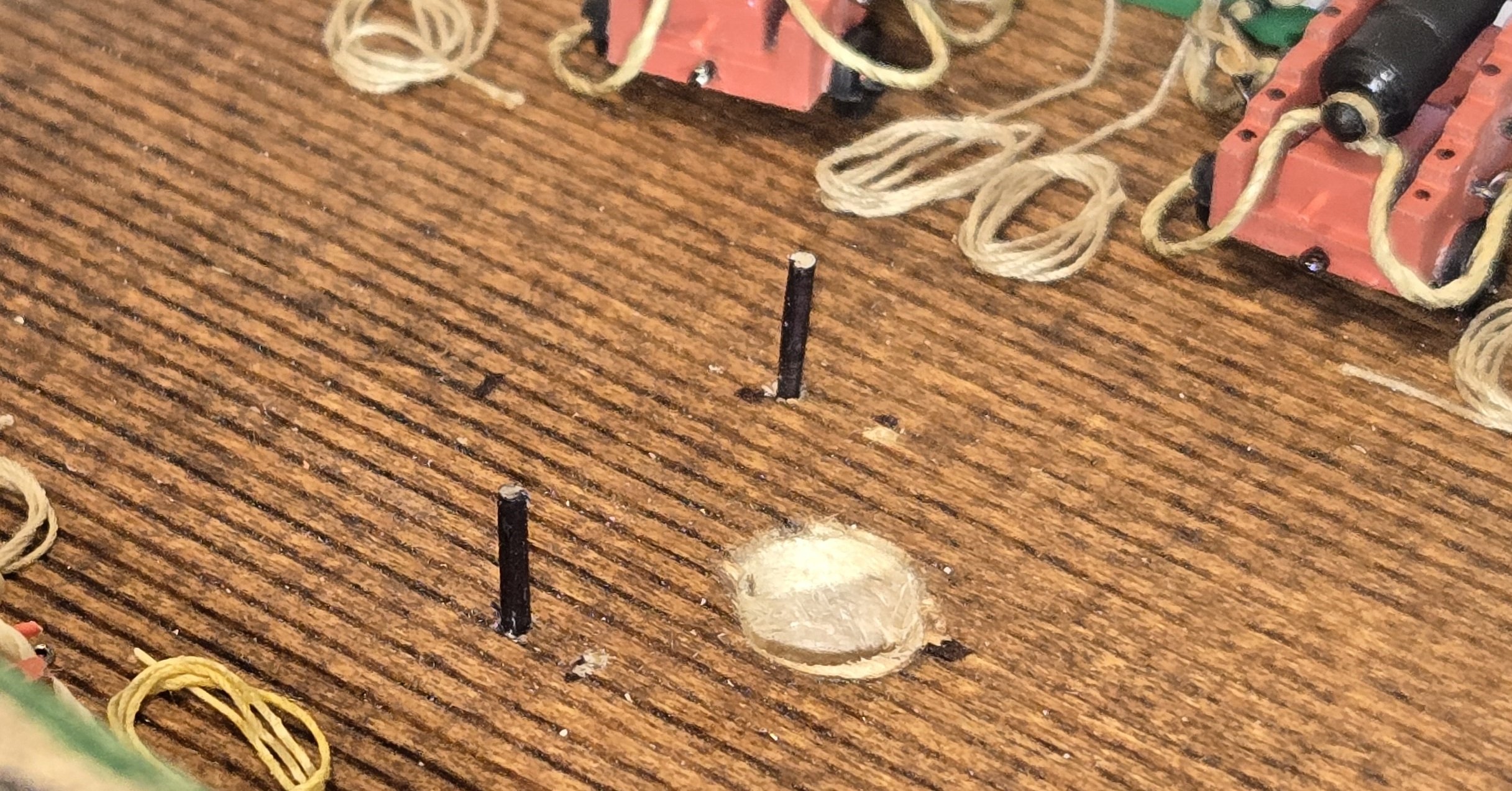
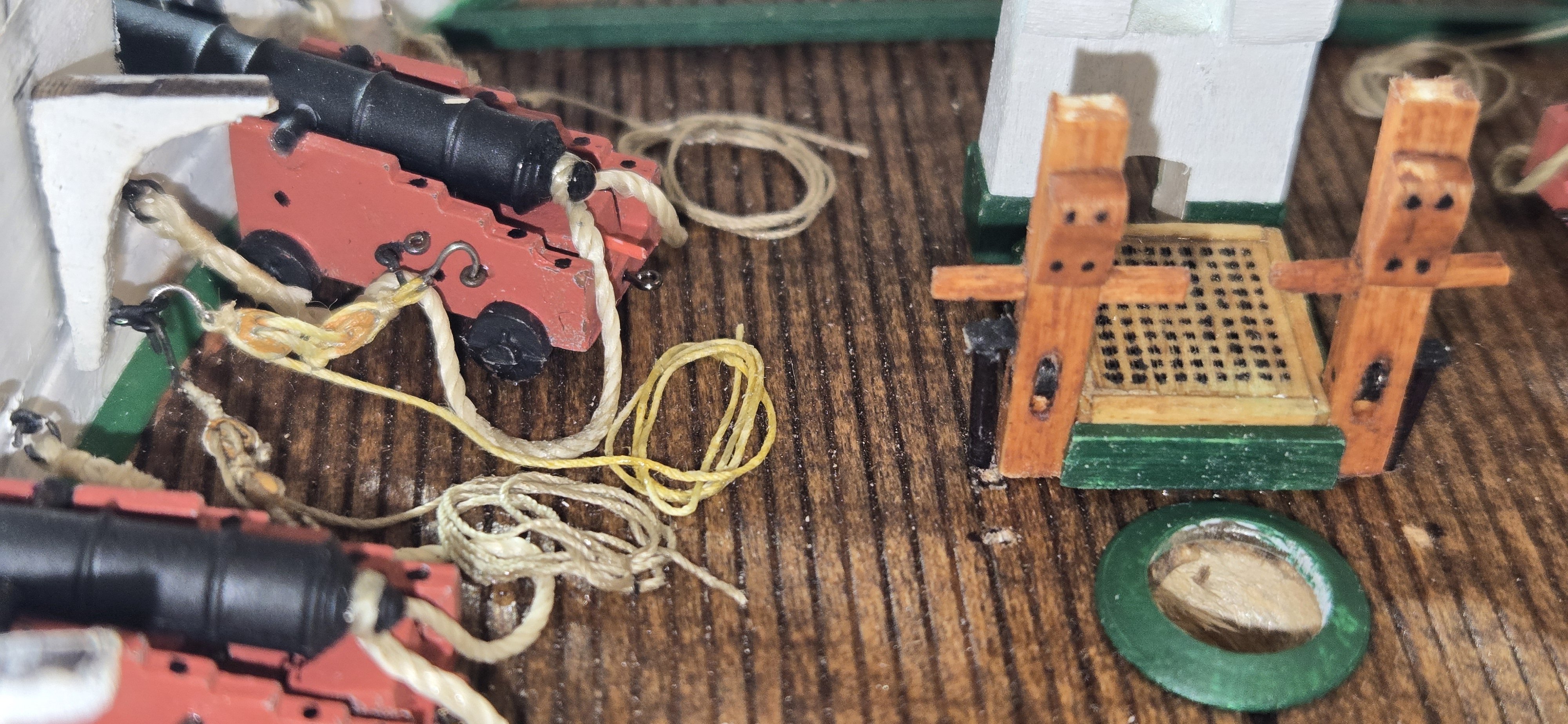
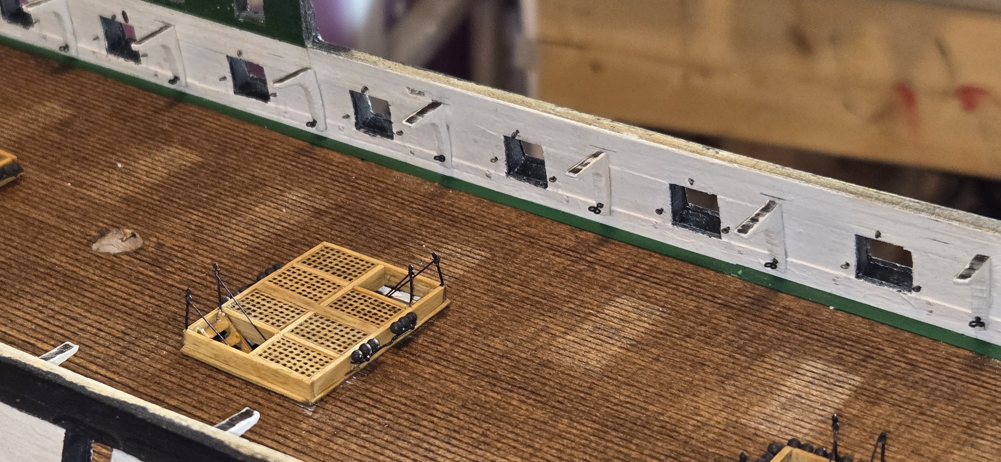
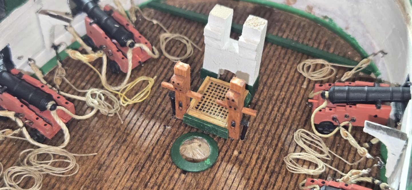
I've started working on the deck furniture. I still haven't had a lot of luck finding out what was in place of the large iron anchor bitts currently on the ship. I contacted the museum and they referred me to the Naval History and Heritage Command. They couldn't give me a definitive answer but provided several good references. The first was The Young Sea Officers Sheet Anchor (1819). It's a kind of text on seamanship and fortunately is available online. In it, they mention the securing of anchor cable to the anchor bitts and gave the following diagram This seems to be pretty standard for ships of the time. I presume in addition to the anchor bitts on the ship now, that a cross piece like this would also have been at the end of the cable riders. I'll probably go with something similar unless I hear something better from anyone out there. I go started with the anchor bitts just in front of the foremast. I used 1/8 squarestock to make these. As mentioned by Jon in his build, there are no dimensions to be found, so everything was pretty much eyeballed and based on comparison to some known dimensions of other items in photos. The height was easy enough since it is based on where the spardeck is to be. The little support knees were spaced to accommodate the height of the deck beams. The cross pieces are a single piece. To get these in place, I first drilled an appropriately sized holed and then squared that up using a square rat-tail file. Lastly the sheave was made from 3/32 dowel that I sliced a tiny piece off of. The hole was created by drilling three small hole and then carefully carving out the remaining wood and finally cleaning up the hole with a flat file Next came the grate for the scuttle that I apparently missed when constructing all the other grates on the deck. This was made similarly to the others using the persimmon wood I still had and the laser engraver. The coamings are slightly different than the other grates. Here's everything after staining and painting but before installation. Note the little tabs on the sides for the rollers that will be put in place once on the deck Next up was the bowsprit bitts. These are pretty stout timbers. Again, I couldn't find any actual dimensions, so I just guessed again comparing to everything around it. From what you can see on the virtual tour and looking at Lord's 1927 deckplan, the timbers are square, with space in between for the bowsprit notch being the same dimensions. So I just took the width of the scuttle and divided it by three. Lord's 1931 deck plan indicate this hatch was three feet wide, so 12 inch timbers (1/8"). The height again was simply based on fitting the spardeck and the support knees positioned to accept the height of the deck beams. The crosspiece in the middle makes a hole to receive the notch of the bowsprit. Instead of making this square, I used a 3/8 dremel sander to curve the bottom. That way, I only need to cut the sides of the bowsprit to make the notch. The coamings around the botttom were made from some hull planking I had left over that I thinned down a little bit, probably to about 1/64"". The wholle thing was secured to the deck using wooden dowels I made from thinned down toothpicks. I notched a 3/8" dowel to be used for the bowsprit so that it would fit the bitts and used that to make sure it was positioned perfectly to accept the bowsprit later and be straight. When installing the scuttle and anchor bitts, I first installed the side rollers. These were made from a 3/32" dowel that I thinned down further. Holes were drilled into the deck to accept the rollers and the bitts were placed on top. Everything was secured with 5 minute epoxy. Here's the final view looking forward


-
Hi Rod, Thanks for looking in on my build and I definitely appreciate the compliment. Wanting to put in alot of details, I'm sure I make it hard on myself, especially at our scale. If nothing else, it keeps me busy. Good luck with yours
-
Welcome to the Connie group Rod. You are off to a great build. Look forward to following along. As slow as I am, I'm sure you will catch up to me soon and I'll have someone new to "steal" ideas from.
-
Thanks Gregg, appreciate the support and thanks to all the likes. Jon. I'll definitely give that a try.
-
Now that I have the forward guns in place, I'm planning to focus on the bitts and deck furniture for that portion of the ship. Originally, I didn't plan on putting much detail in the very forward part of the bow since it wasn't going to be very visible if at all, but I've decided to go ahead and put everything in place just because I will know it's there. Immediately, I had some questions. In the manger area, there are currently two chain stops, port and starboard I know in 1812, they did not have anchor chains, but instead, hemp cable. My question for all is would there still have been a similar stop for the cable? The second big question is the about the chain bitts. The instructions in the kit say "the large iron bitts" were not present in 1812. I assume these are what they are talking about: so the question is, what was there? Any help would be greatly appreciated


-
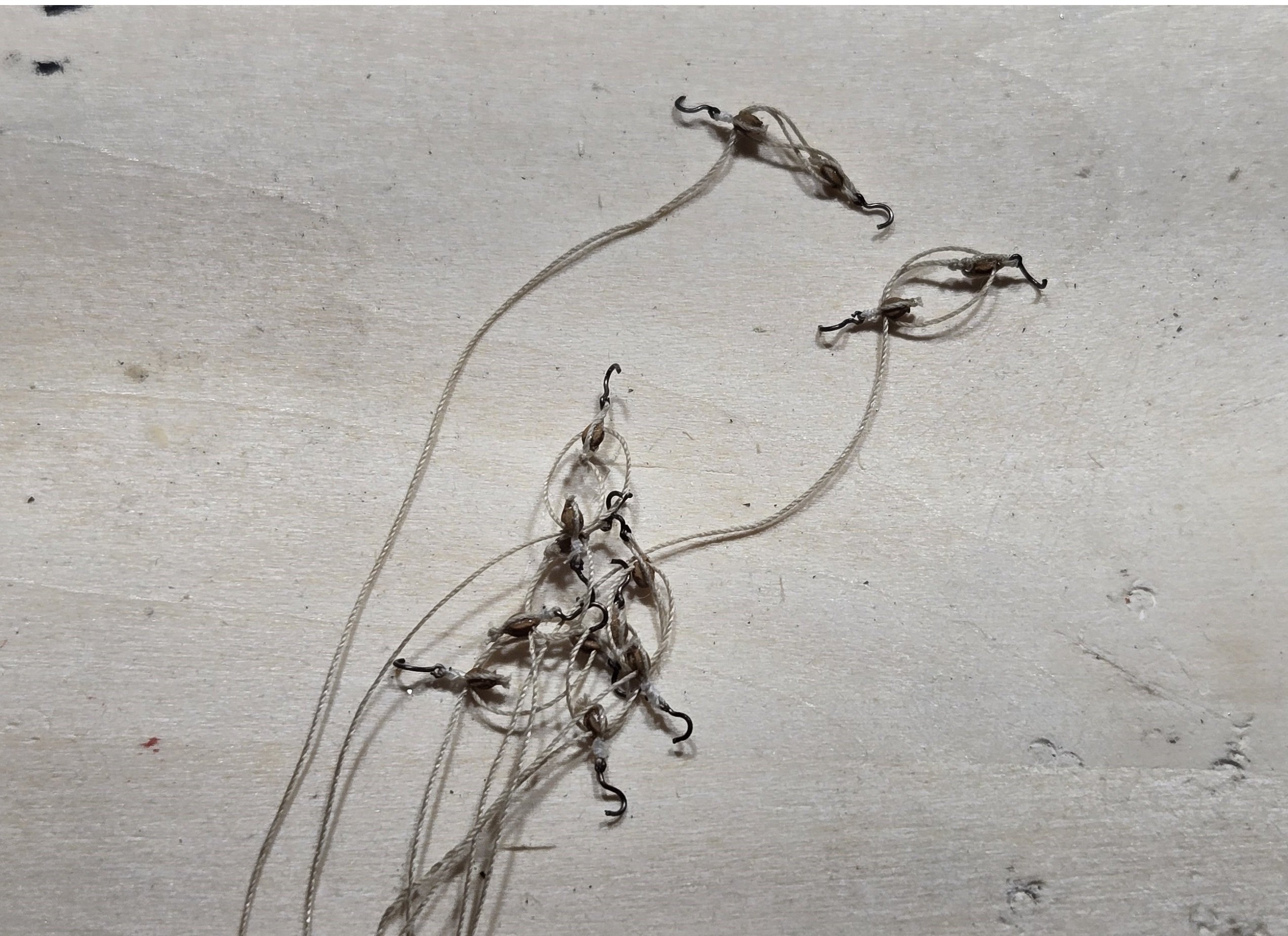
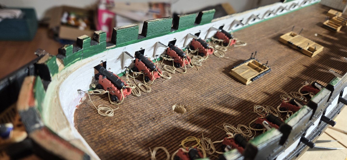
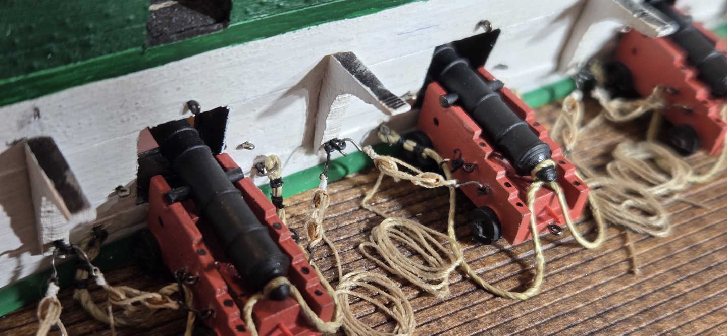
After getting a few of these put together, I started using a alligator clip to hold them so I didn't end up with a tangled mess. Also, once I got them put together, I felt the hooks, although pretty tiny, were a bit out of scale. I just have to live with that, because I don't think I could make them any smaller. For the breeching lines, I found it was much easier to put the rings and eyebolts on them first and seize the ends instead of trying to open up the rings to get them on and then trying to close them back up. After putting the rings on and seizing the ends, I attached the eyebolts to the carriages and secured the breeching line to the cascobel. With the guns assembled, they were glued into place. I had previously drilled a hole in the bottom of the carriages to accept a pin that I had inserted into the deck. To secure the carriages, I put a tiny drop of 5 minutes epoxy on the pin and the bottom of all four wheels. Once the glue had set up and the guns were secure, I attached the eyebolt on the ends to the bulwark in pre-drilled holes. Finally, the hooks on the tackles were attached to the carriages and bulwarks. Before attaching the tackles, the free ends were coiled up and the coils made secure with a miniscule amount of CA. Once all was in place, all the ropes were secured to the deck with a little CA to keep everything flat and to try to give everything a natural sag.
-
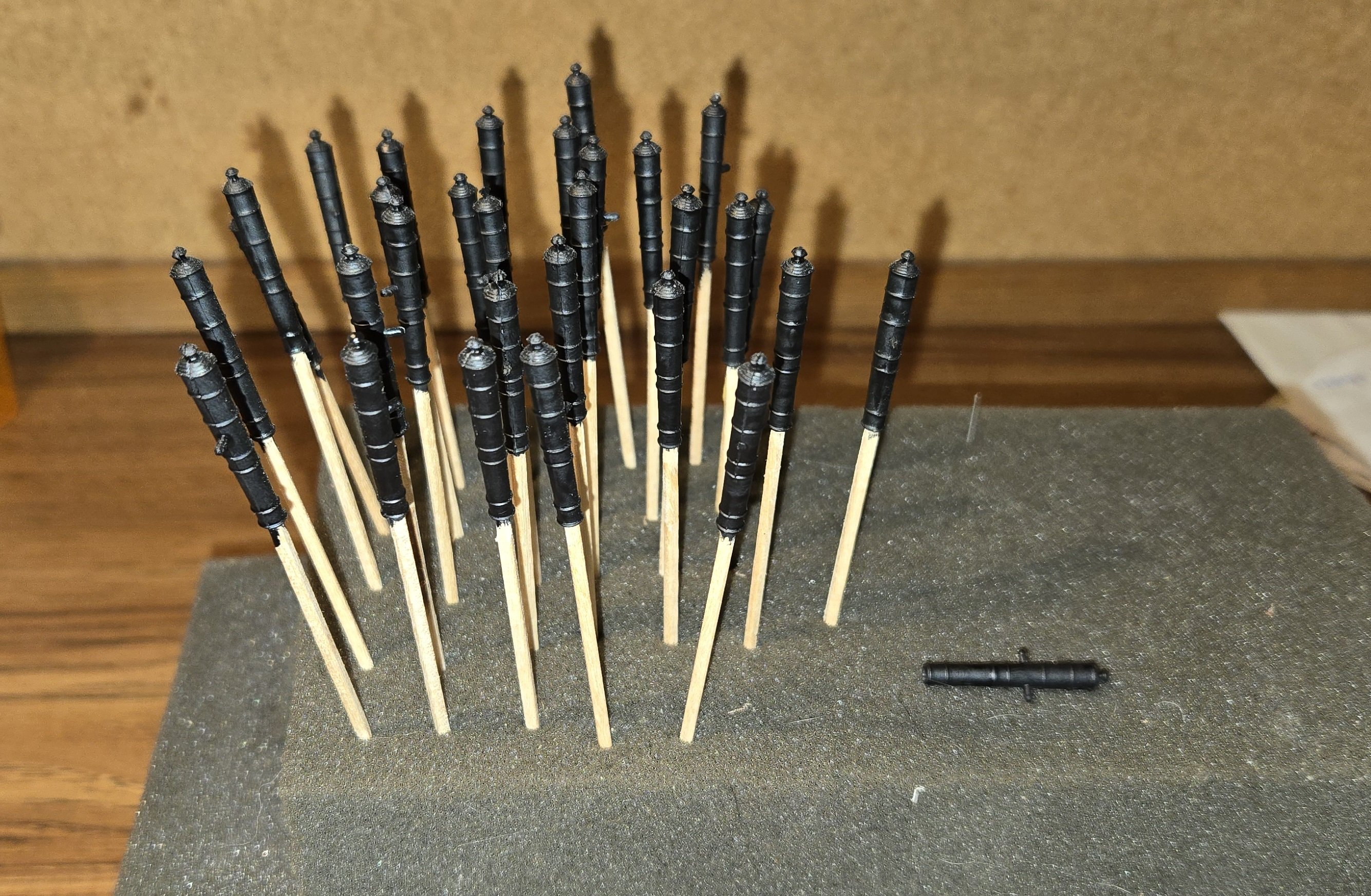
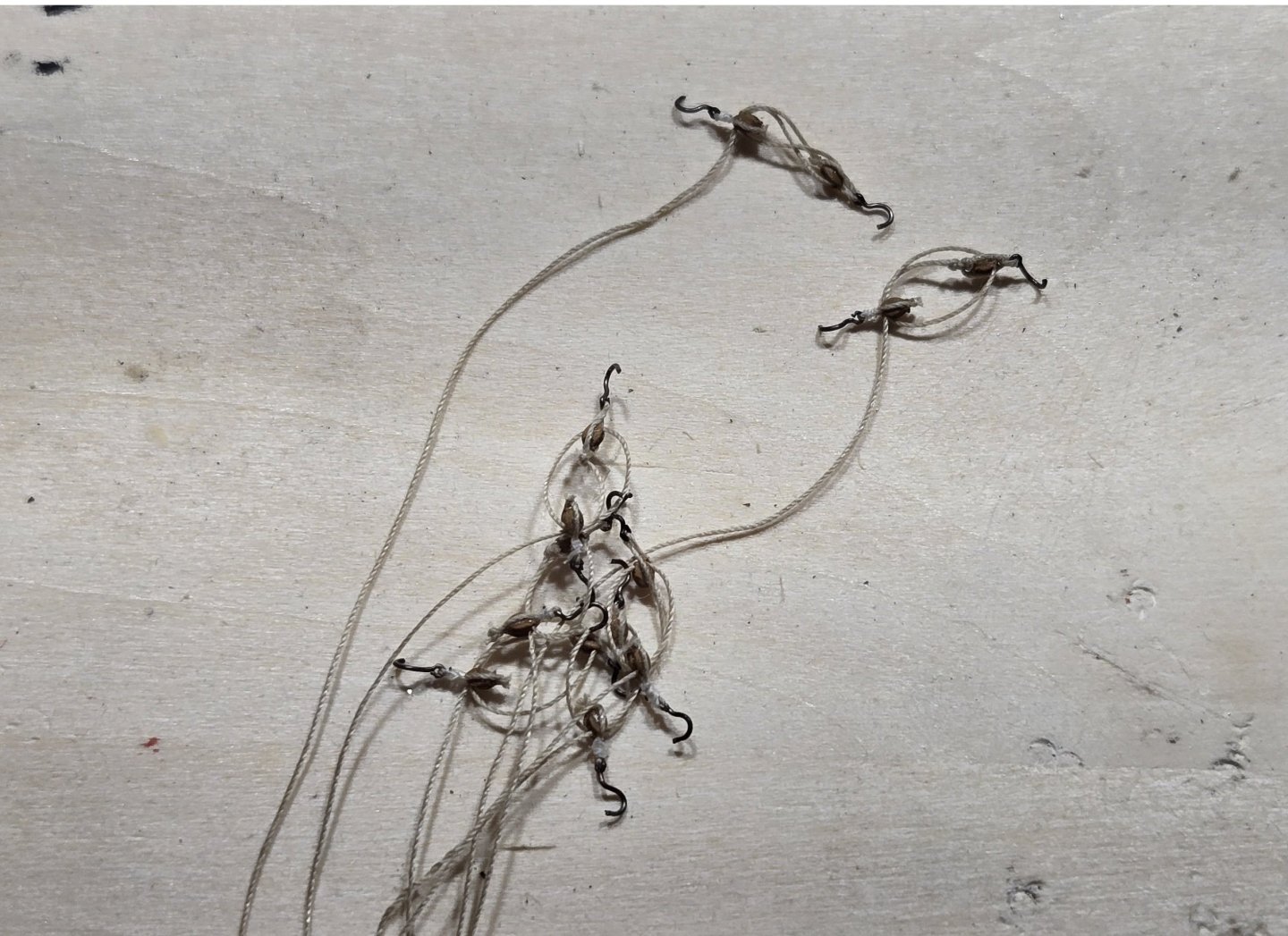
Hello All, After a long holiday hiatus, I felt it was time to get back to work, so a quick update. I've trudged along, stropping and seizing my blocks with hooks, and then assembling the tackles for the guns. I got through about 50 blocks (25 singles and 25 doubles). It's pretty tedious, and to break up the monotony, I decided to do like Jon and install a few guns on each side then work on the deck fixtures before moving further down the ship. Here's a pic of a few of the assembled tackles as I was going
-
USS Constitution by mtbediz - 1:76
g8rfan replied to mtbediz's topic in - Build logs for subjects built 1751 - 1800
I am in total awe. I can only hope to be half as good. When I do get above the spar deck, I think I may have to break down and purchase a proxxon on mill. -
Coming along nicely Jim. Good job on the catheads. I presume you used the eyebolts supplied in the kit, which are 1/32. These are definitely a bit out of scale for most of what we use them for. I've been using fly hooks, which I assume you are familiar with. Sizes 16-24 seem to be most appropriate. Just cut the shank to the appropriate length. A bit pricey here in the states, but you can buy a pack of 100 from China (Temu) for $6-8. Keep up the good work
-
USS Constitution by mtbediz - 1:76
g8rfan replied to mtbediz's topic in - Build logs for subjects built 1751 - 1800
Mustafa, this ship looks amazing. I can only hope mine is half as good when it there -
Thanks Steve, it definitely is a challenge working at this scale.
-
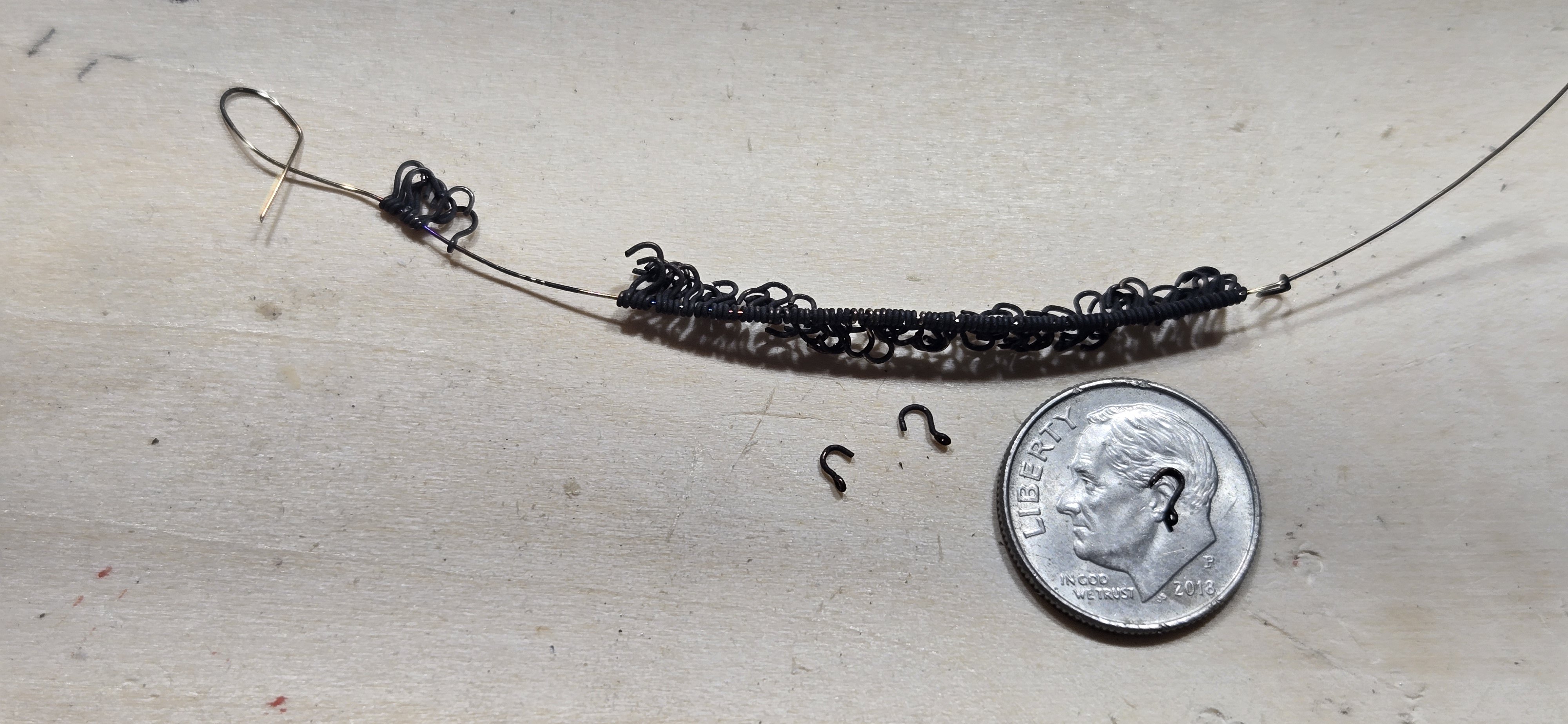
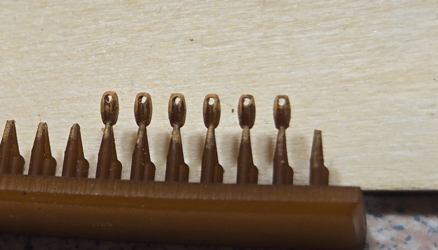
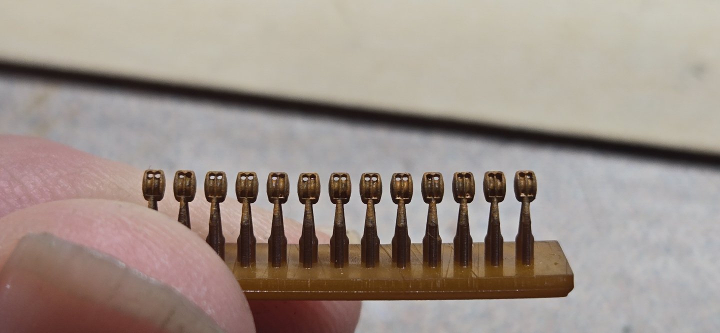
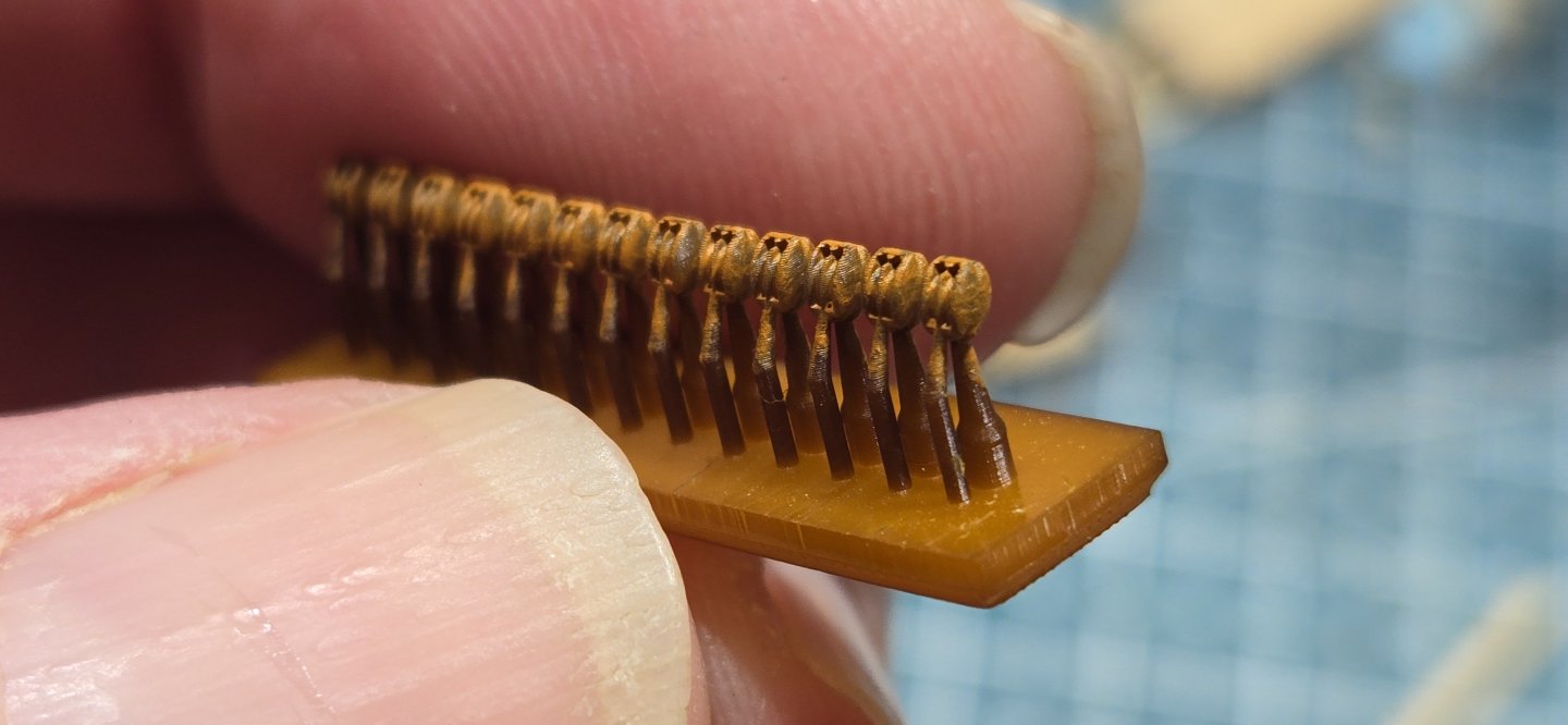
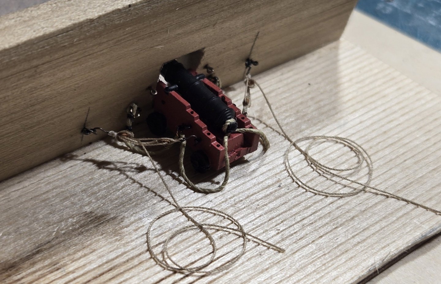
Hello All, As usual, it has been a while since my last post. Not that I have been idle, just moving slow I guess. I received the 3D printed blocks from the UK and at least in my inexperienced opinion, they are great. The detail is very good,and the color is basically like a walnut. They could be used as is with no problem. Based on the look of what they are on the ship now, I thought they needed to be a little lighter, so I gave them a wash with Model Expo hull Umber. Unlike the metal cast blocks, the plastic resin takes paint well and once dried it doesn't rub off. Here's a few pics Singles Doubles These are 2mm in length. they break cleanly away from the supports and really need no cleaning. Of course threading these tiny little things was challenge. I also received a bunch of fly fishing hooks in which to make the hooks for the blocks. With 30 guns and just the side tackle, this meant 120 hooks. Unfortunately, the ones I received were more of a bronze than black. I tried using Brass black to darken them, but it did nothing, so they got painted I'll need another 60 of these to do the out haul tackle, but I'll get to that later. I found when stropping the blocks that with just glue holding the line together around the hook, when I pulled it tight around the block, the line would separate, So, I decided to go ahead and seize these. The BJ kit supplies some .005" line, so I tried using that. Surprisingly, it wasn't as hard as I thought it would be, but the line is bright white and just doesn't look right. It's also a little thicker than it should be I did a little looking around and once again I'm turning to the fly fishing world. To tie flies, they use some pretty fine threads. I settled in on some Flymaster 8/0 that is .0026" and comes in a perfect tan color. I thought I would be able to get this at the local Bass Pro shop, but unfortunately, all they had was black I've ordered the tan from an online store and hoping that arrives by Monday. Meanwhile, I tried the black line to seize the breeching ropes. I really liked the way it turned out and put one together on my little mock up gun port: I know there should be triple seizing and the ring for the breeching line should be in the middle, not the front. All that will be fixed when I actually install them on the ship, I really just wanted to see how everything was going to look. Now I'm just waiting on the mail


-
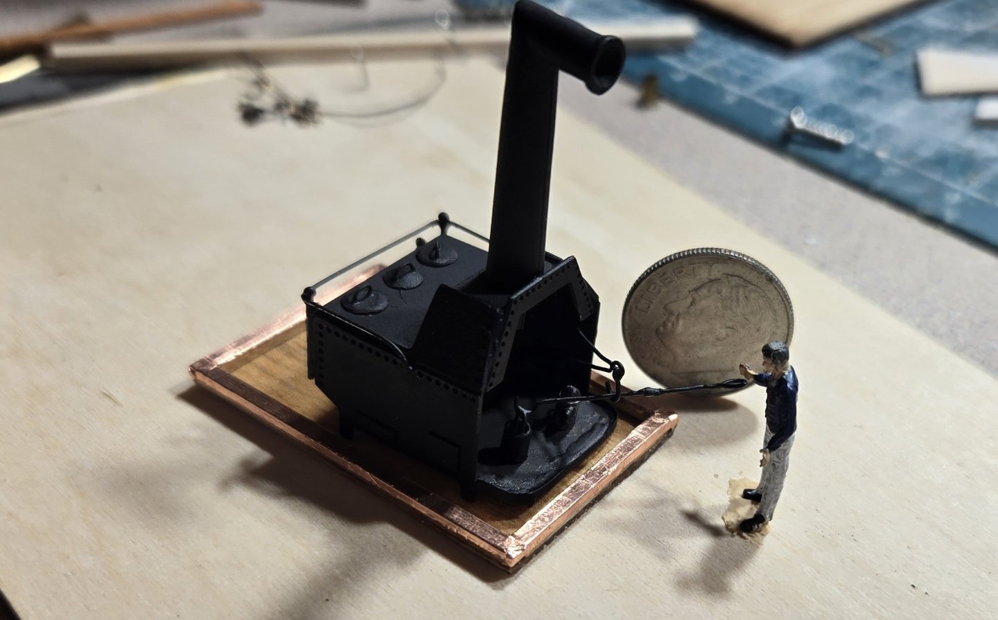
The photo above has no scale, I thought I would add this to give some perspective
-
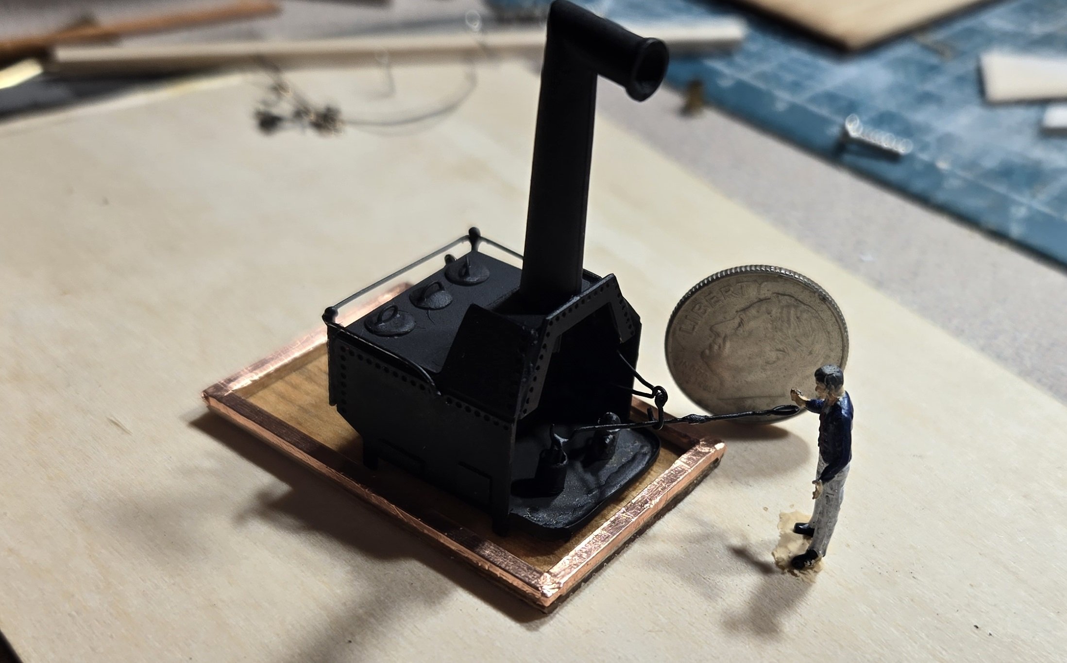
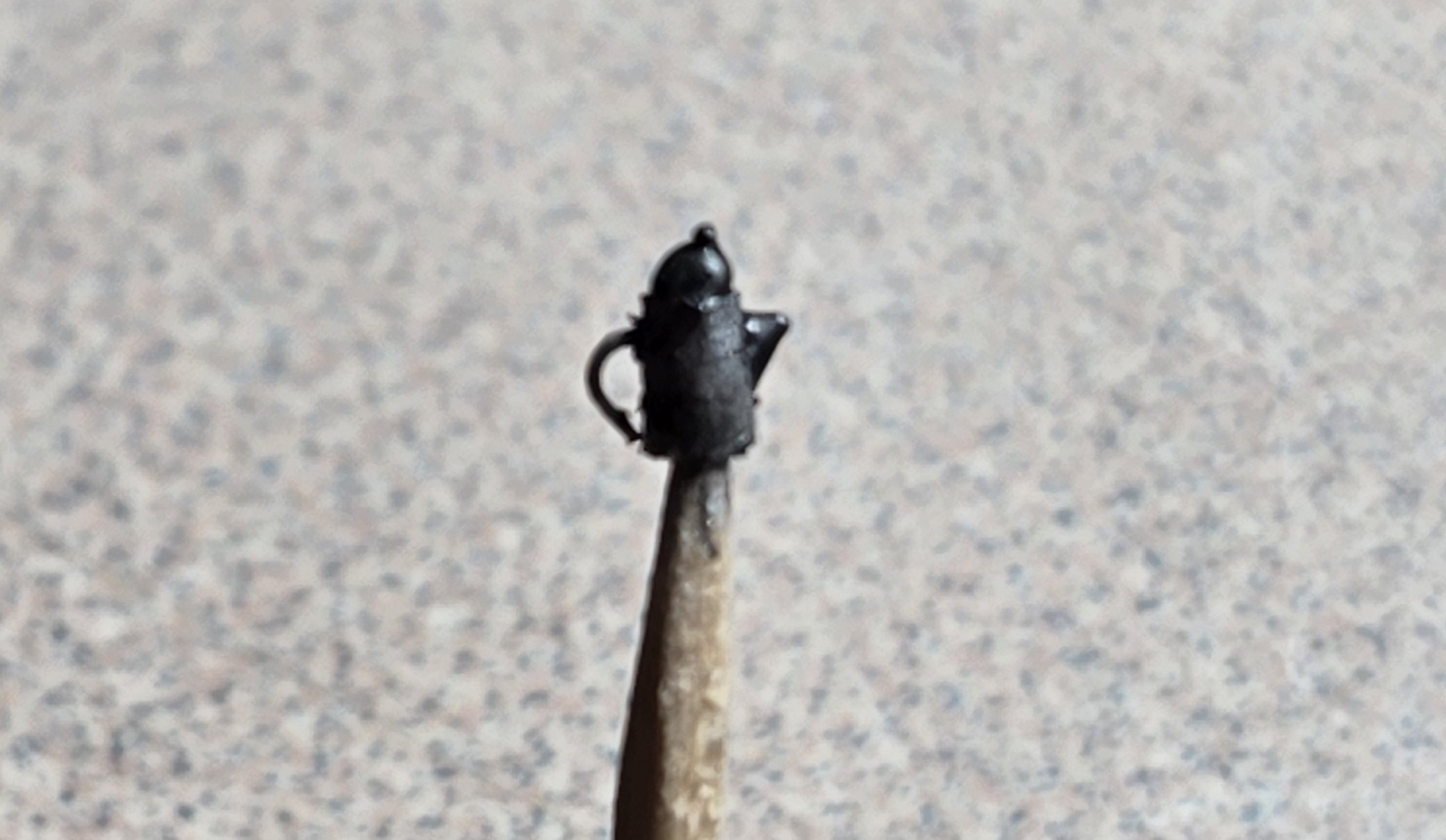
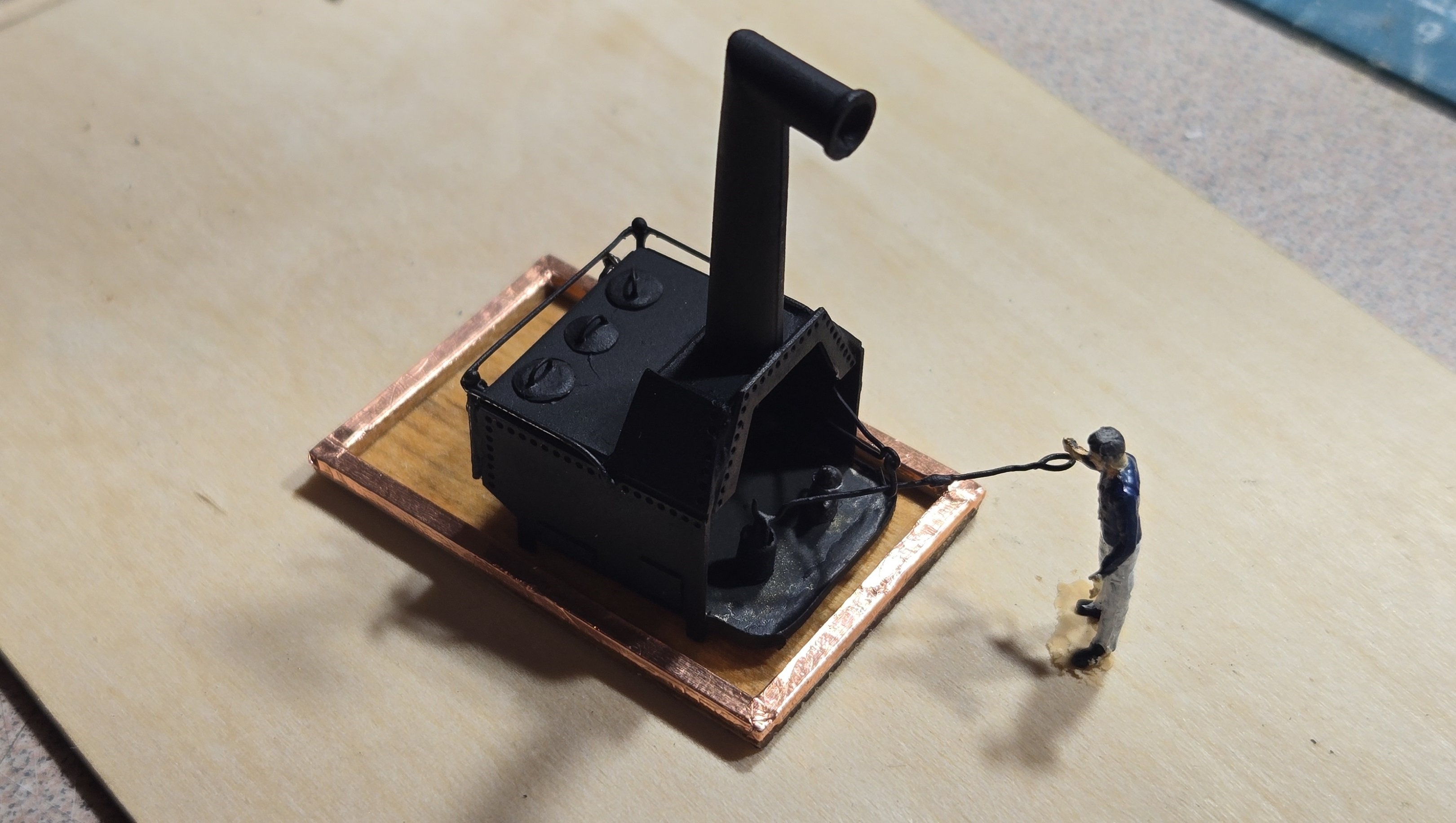
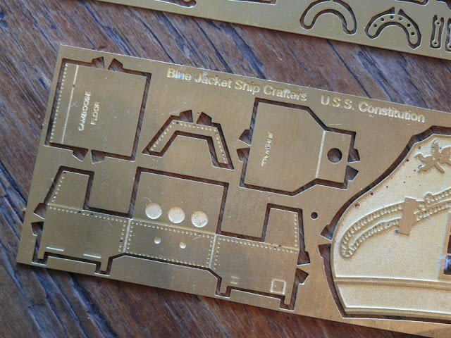
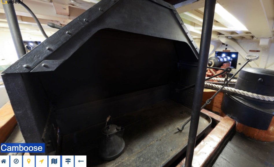
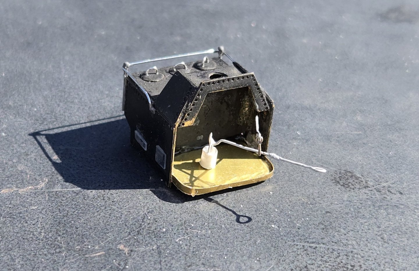
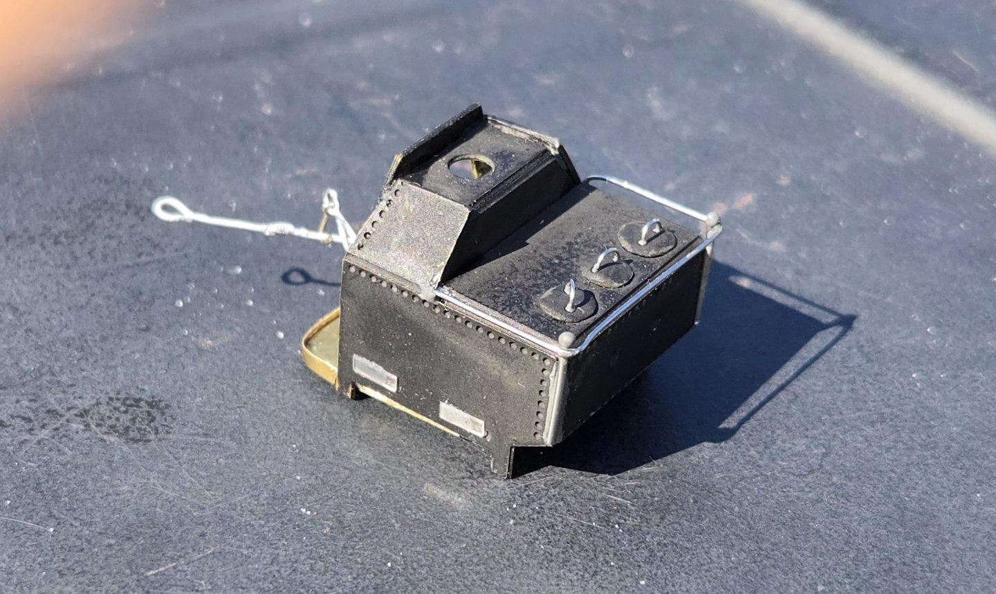
While I've been waiting for my blocks to arrive, I figured I would use the time to start on some of the other gun deck features. The instructions say it is best to start at the bow and work your way back, and one of the most forward features is the camboose. So, that's what I jumped on. The kit supplies a photoetched piece that has grooves cut allowing it to be easily folded up into the proper shape: It's pretty straight forward and everything fits together nicely. Once folded up, I decided to solder the seams instead of gluing to give a nice tight structure. The floor has a straight lip that folds up. Looking at the actual camboose on the ship though, this front piece is curved. I decided to make mine more like the ship's, so I filed the corners of teh floor to have rounded corners and cut a thin strip of brass sheet to make the lip. That was soldered into place. Although the photoetched piece has little impressions where the side doors would be and the stove lids would be, these are flat and sorta featureless. I definitely wanted to do better. The side doors I simply cut some rectangular pieces of sheet plastic and glued in place just to give some dimension. The lids on the stove I made from brass sheet. I cut out little circles using scissors and gave them a dome shape by pressing them with a steel rod I had rounded over on the end. I made handles from 28 ga. wire and glued those on with epoxy. The rail going around the top of the stove was made using 24 ga wire and the supports for the rail were made from 22 ga. wire with a little blob of epoxy for the ball on top. everything was attached using epoxy. I probably should have stopped right there, but I had time to kill and just couldn't help myself. Here is a shot from the self guided tour on the museum website I decided that I would make everything in this photo, plus a little extra. First up, the coffee pot. I started out using 4 mm styrene tubing. Using a nail file, I tapered that down and then cut to length to give me the pot. Then I used epoxy (JB weld) to make the lid and the pour spout. Finally, I used 32 ga wire to make the handle. Here's what I ended up with after painting. Not bad if you ask me. Then there was the pot lift. This was made from 28 ga wire. I used round needle nose pliers to make all the bends and curves and added a little drop of epoxy in the middle as a "stopper". To me, it wasn't enough to have the lift. It needed a pot. so, using the same styrene tubing, I thinned the walls by drilling out the center and then added a handle made from 32 ga wire. To top it all off, if you look closely in the tour photo, the lift is suspended from a hook, so, I added a hook to hold it. Here's my stove, that no one other than the people on this forum, me and God will ever see The base I made from 1/16 stock glued to a leftover piece of scribed decking(upside down) with copper tape - same used for the hull. Before installing on the deck, I plan to paint the floor pan dark grey with a black wash. After I took the photos, I realized that I forgot to add the ring bolts on the back side (I presume for lifting). These have now been installed. Way over the top I know, but it was fun


-
Hey Jim, Glad to see you're still working at it. I definitely feel your pain regarding the instructions. If it weren't for this forum, I don't think I would have gotten past this part. The galleries were tough, but the bow is even worse. My suggestion to you would be to take a good look at Jon's ( @JSGerson ) build log starting at post #675. He gave a nice step by step of how he did it with some great photos. I built my bow a little different than the current configuration, but I still used the basic structure, just a different number of bowhead timbers and a different second rail (the one that fits under the catheads now). Couple of things to keep in mind: The bowhead timbers (rail supports) rest on top of the "knee" that is basically the top rail of the trailboard. The grating rests on cross timbers that sit on top of the stem. It is best to get the rails in place and then fit the bowhead timbers to them, not the other way around. You can precut the bowhead timbers to a basic shape, but then you just have to trim and shape them a little at a time until they fit. Hope that helps a little.
-
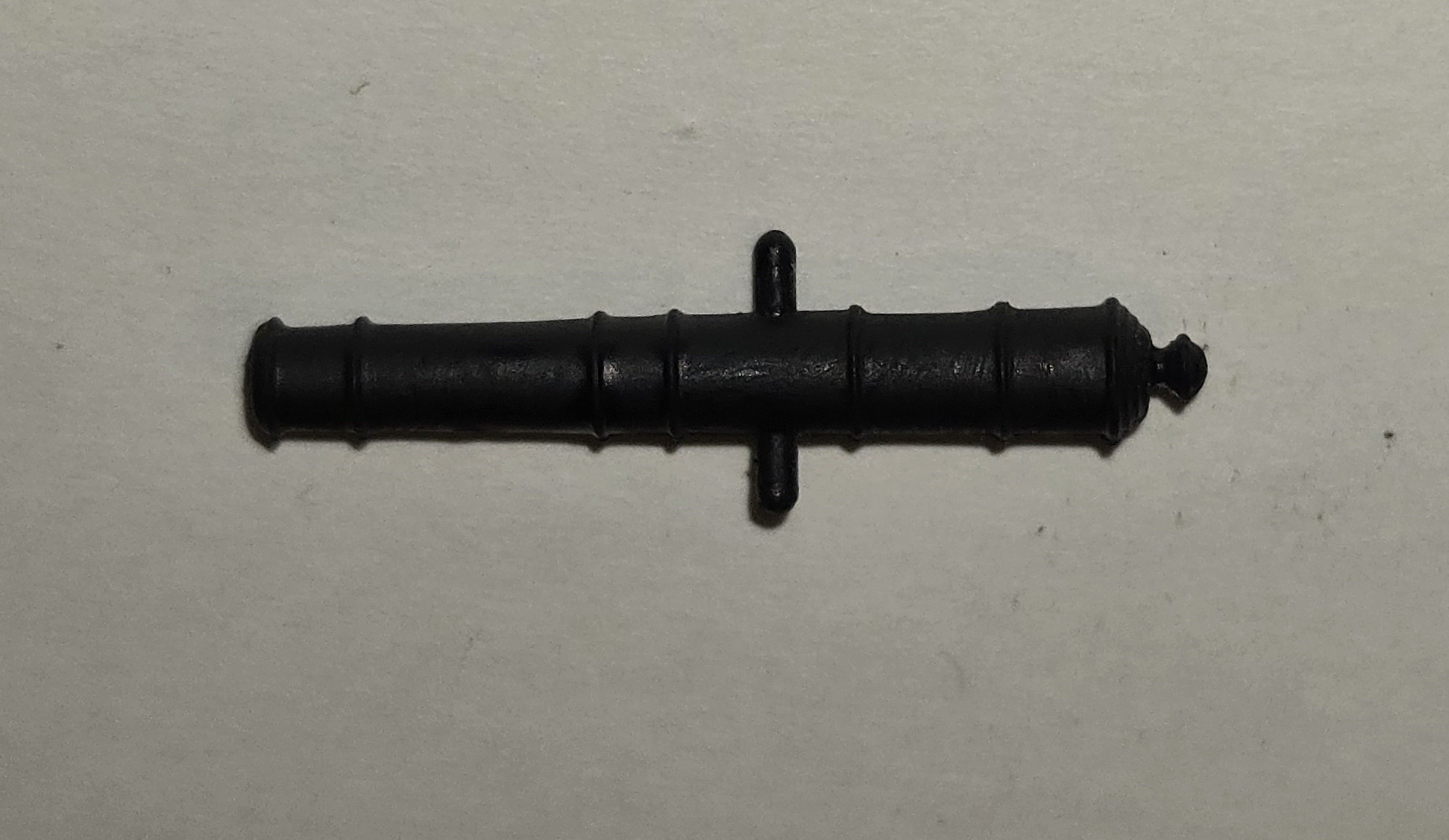
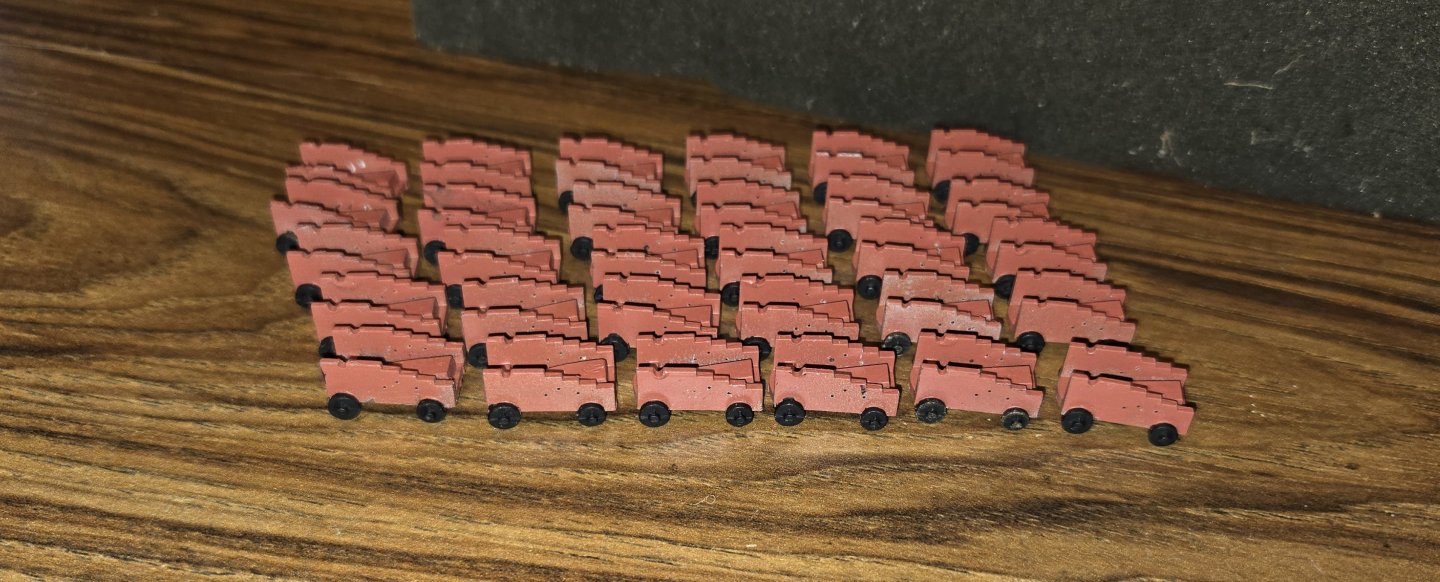
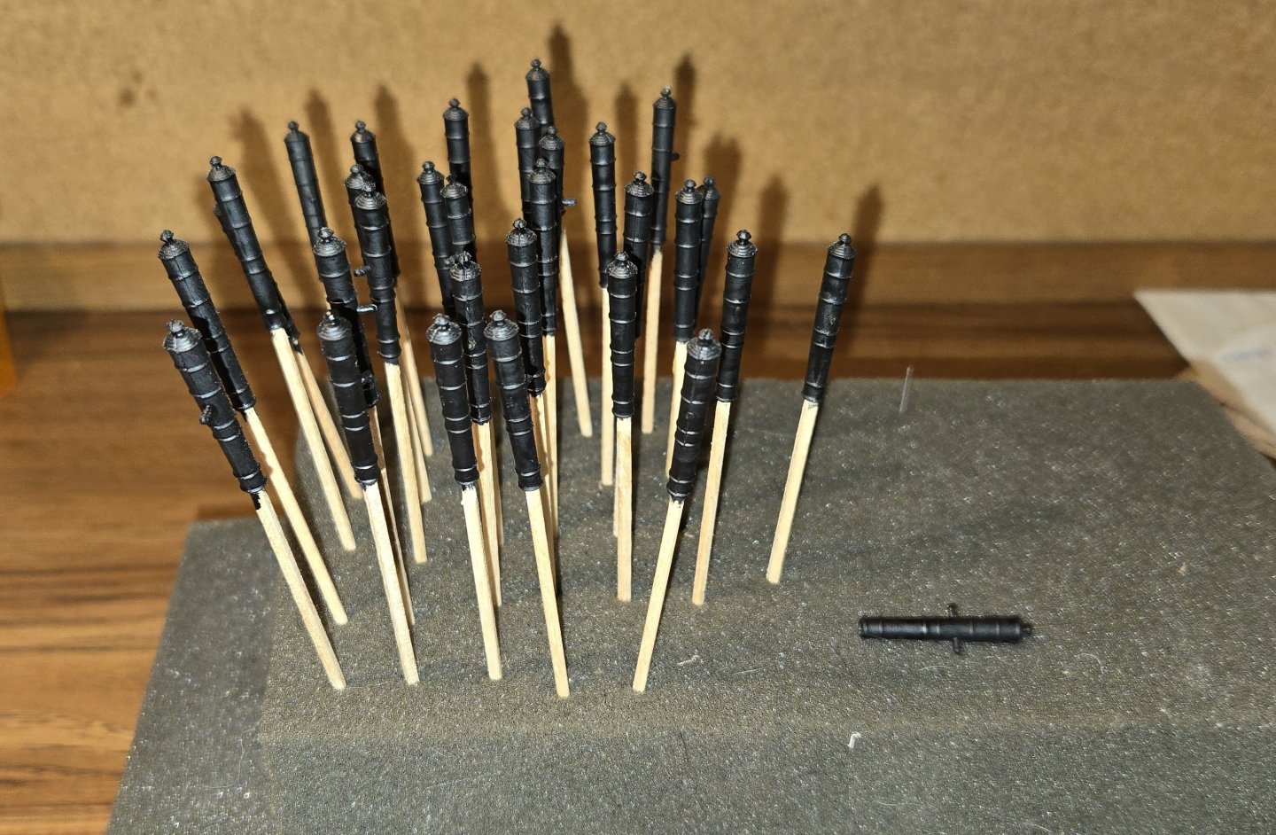
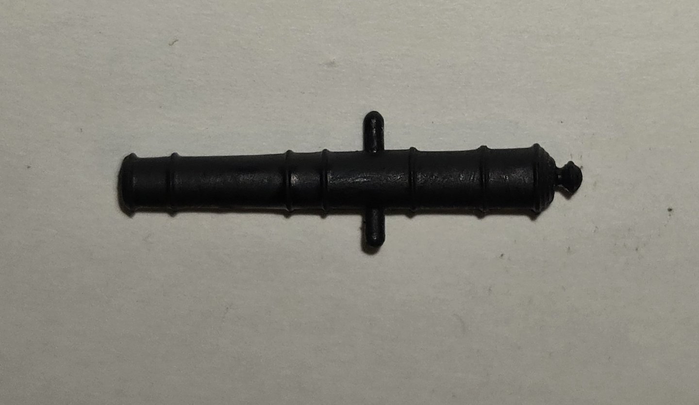
So, moving right along, having got the knees in place and all the eyebolts attached, I planned to get to work on the guns. I figured it would be best to work my way from the out side inward, since the guns were going to be difficult enough to put in place. The carriages supplied with the kit are cast metal, with the trucks separate from the body. As with alot of these cast metal parts, there is a good bit of flash that needs to be cleaned up. I took a look at the carriages in the plastic Revell kit, and they were alot cleaner. They are all one piece, The bottom is solid, which is not really accurate, but that wont be visible at all once the cannon is in place. I decided to use the plastic ones. Although painting the wheels was going to be more difficult with them already attached, I figured it would be easier than cleaning up the cast metal ones. Trying to match the color of the carriages was a bit of a challenge. To me, the color is kind of a brick red, with a touch of terra cotta. Not a color paint that I could find, at least that I was happy with. I ended up mixing a color that I was satisfied with, 60/40 Vallejo SZ Red/ Hull umber and a bit of flat flesh. Next were the guns. Once again, the kit supplied guns are cast metal. The details are nice, and the cast metal has a nice surface to it. There were two main draw backs for these. The trunnions had a very significant bit of excess metal that needed to be trimmed away. Instead of a nice pin sticking out, it was more like a triangle. The other thing I wasn't happy with were the barrels. These were solid and flat on the end, unlike the carronades, which are concave, giving a guide for a drill to follow. With a flat end, it was very difficult to center a drill bit. I used a small drill bit to first drill a hole in the center as a guide, but even with that effort, I still managed to blow out the sides of a half dozen or so, when switched to the larger bit. Again I went back to the Revell kit. The cannons in this kit come in two halves that have to be glued together. Unfortunately, the person I purchased this kit from had already glued these all together, and did not do that great a job. Many of the seams had gaps, none of the flash had been removed and on several of the pieces, the halves were not lined up well. Still, the barrels are hollow, and the details were very nice, so I decided to try and clean them up. The whole process went very well, and although I did manage to knock off several of the trunnions, I was very happy with how they turned out. I'll use some wire to replace the trunnions that didn't survive the clean up. Of course, I'm planning on totally detailing the guns. Although the proper scale for the carriage eyebolts would be using the #24 hooks, these are so tiny and getting any thread or hooks into them would be at best, very tedious. I decided to go with the #16 hooks instead. These are still pretty small, with a wire diameter of .015" and an eye diameter of .048". For the ring to hold the breaching line, I purchased some 2mm jump rings. In order to get the tackle the right length and everything, I did like many of the builders here and put together a little mockup of the gun port. The kit comes with 1/32" blocks that are cast metal. These are surprisingly well done, shaped well with nice detail and clean holes. There is a little piece of sprue on the end that has to be trimmed off, but that was not difficult. The only draw back to them over real wood blocks is that they have to be painted. Painting them ahead of time is pointless. Even with primer, the paint tends to rub off with handling and if one is not very careful, the holes will get plugged and need to be drilled out again. So, they have to be painted after stropping and installing the lines, which is not easy, but can be done. Handling these tiny little pieces of course is not easy. Being totally new to all this, I definitely had to develop some skill and technique with holding them. In the process of learning this new skill, several of them pinged off like tiddly-winks, never to be seen again. Stropping the tiny things was another challenge. At this scale, seizing would be ridiculous. I was satisfied with just a drop of CA and pinching the rope together. The hooks were made from eyebolts, cut from #24 fish hooks and bent with round needle nose plyers used for jewelry making. All in all, they turned out really good. here is what my first attempt looked like: I originally planned to include the in-haul tackle, but after doing the side tackle, I realized how crowded it was going to get, especially once the breeching line was in place. Since all of this is going to be barely visible, I think i will just have the one set of tackle for each gun. I do plan on having the out-haul tackle on the backside. It was at this point that I realized the kit did not include blocks for rigging the guns and these needed to be purchased. At first, I was going to just buy more of the cast metal blocks, but thought if I'm going to buy them anyway, why not look into getting real wood. As I was looking at sources for wooden ones, I came across a fella in the UK who makes 3D printed blocks that are colored like wood, and very reasonably priced. Decided to go with those and I am now waiting for them to arrive. I also purchased some .008 rope from Syren.


-
I got all the hanging knees cut out using the laser. These were then individually numbered and shaped to fit the bulwarks. The eyebolts for the side tackle are located on these knees and are "double" eyebolts. To make these, I made a little jig by drilling two small holes, very close to each other, in a piece of wood. I inserted very stiff wire into these holes and cut them short. The eyebolts were then made by wrapping 26 ga. wire around the two wires like this Here's what I ended up with The long ends were glued together with CA to keep everything tight. I then drilled a hole into the front of each knee and inserted an eye bolt with a little epoxy to hold it in place. Once the epoxy set, the long piece sticking out the back was cut flush. Of course the knees and the eyebolts were painted prior to assembly. Finally all the knees were glued into place I also made up all the diagonal knees, but I'm going to wait to install these until I'm ready to put the spar deck beams in place. Next, I'm going to get started on the guns