


Greg Davis
-
Posts
807 -
Joined
-
Last visited
1 Follower

About Greg Davis

- Birthday 05/29/1959
Recent Profile Visitors
3,402 profile views


-
 Maid of the Mist reacted to a post in a topic:
HMS Beagle by Maid of the Mist - FINISHED - OcCre - 1:60
Maid of the Mist reacted to a post in a topic:
HMS Beagle by Maid of the Mist - FINISHED - OcCre - 1:60
-
Cathead reacted to a post in a topic:
HMS Beagle by Maid of the Mist - FINISHED - OcCre - 1:60
-
Maid of the Mist reacted to a post in a topic:
HMS Beagle by Maid of the Mist - FINISHED - OcCre - 1:60
-
Greg Davis reacted to a post in a topic:
HMS Beagle by Maid of the Mist - FINISHED - OcCre - 1:60
-
 You may have some success using a vice - after filing / sanding / cutting the first flat, put that side to one of the vice jaws and make a second flat using the top of the jaws as a guide, rotate 90 degrees and repeat, ... You may find Amazon and / or a local hobby store - even Hobby Lobby a quicker location for picking up wire and wood to finish your build. Regardless, your HMS Beagle is looking really nice! Happy New Year Greg
 -
Ronald-V reacted to a post in a topic:
La Couronne 1637 by Greg Davis - Corel - 1:100 scale
-
DARIVS ARCHITECTVS reacted to a post in a topic:
La Couronne 1637 by Greg Davis - Corel - 1:100 scale
-
GrandpaPhil reacted to a post in a topic:
La Couronne 1637 by Greg Davis - Corel - 1:100 scale
-
Unfortunately she has been placed on the shelf for a while - right where I see her every time I use my computer! I should get back because I really want to rig that model; however, I've gotten myself involved with a few other projects that are currently taking precedence, including a solid hull model of a pilot ship Gracie S. over on SoS, as well as a large commissioned model. So its going to be a while before another big dose of time is spent on La Couronne. Thanks for checking in - and I have been periodically taking a look at your massive Sovereign of the Seas project - such an undertaking to do what you are doing! Greg
-
Greg Davis reacted to a post in a topic:
HMS Beagle by Maid of the Mist - FINISHED - OcCre - 1:60
-
Geowolf reacted to a post in a topic:
HMS Terror by Greg Davis - OcCre - 1:75 scale
-
Geowolf reacted to a post in a topic:
HMS Terror by Greg Davis - OcCre - 1:75 scale
-
Scott Crouse reacted to a post in a topic:
HMS Terror by Greg Davis - OcCre - 1:75 scale
-
 Greg Davis reacted to a post in a topic:
HMS Beagle by Maid of the Mist - FINISHED - OcCre - 1:60
Greg Davis reacted to a post in a topic:
HMS Beagle by Maid of the Mist - FINISHED - OcCre - 1:60
-
 Greg Davis reacted to a post in a topic:
HMS Terror by Greg Davis - OcCre - 1:75 scale
Greg Davis reacted to a post in a topic:
HMS Terror by Greg Davis - OcCre - 1:75 scale
-
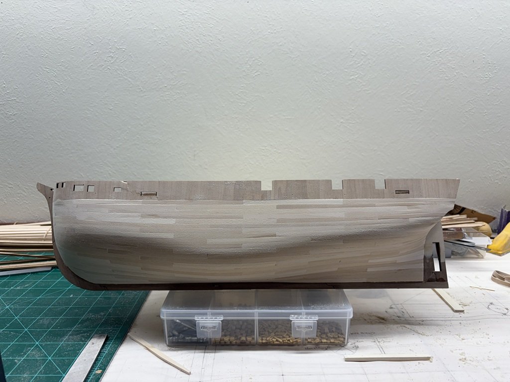
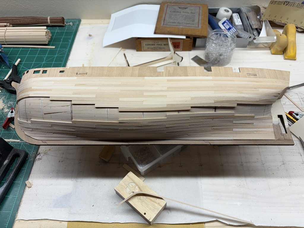
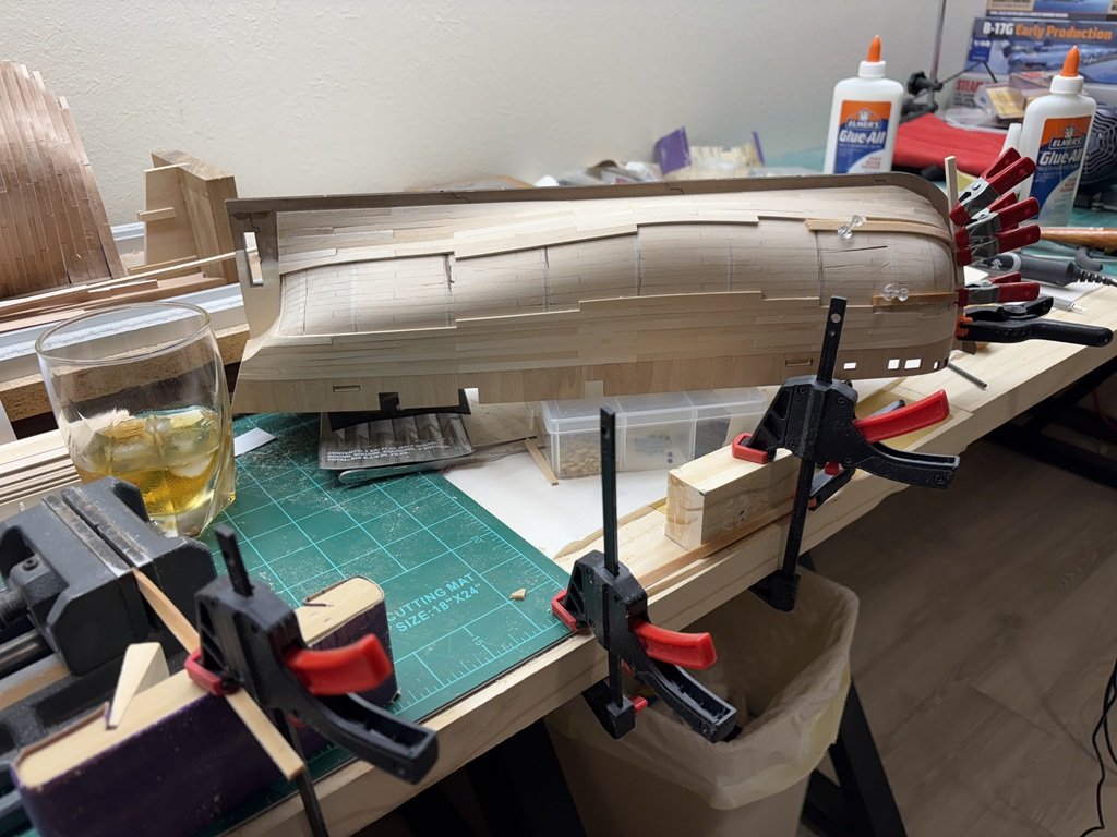
The port side planking is finally complete. It also got 15 min of smoothing before I decided it was too cold to sit outside any longer. But enough was done to get a look at what the hull is looking like now. Difficult (for me) to plank using the kit-supplied wood. A number of the planks would have been easier to fashion out of sheet wood / wider strips. There are a few 'gaps' that will need to be attended too, but all should be fine since the hull will be painted. Nevertheless, it has been a 'fun' experiment. Hopefully the starboard side will go quicker - or at least more easily! After the whole hull is planked, I'll do the rest of the sanding and get on to the ice channels. I don't foresee the need to do a second planking. Not sure when the next update will be as I think I'll be giving additional attention to a few other projects.
-
Greg Davis reacted to a post in a topic:
HMS Beagle by Maid of the Mist - FINISHED - OcCre - 1:60
-
Greg Davis reacted to a post in a topic:
HMS Beagle by Maid of the Mist - FINISHED - OcCre - 1:60
-
Greg Davis reacted to a post in a topic:
HMS Beagle by Maid of the Mist - FINISHED - OcCre - 1:60
-
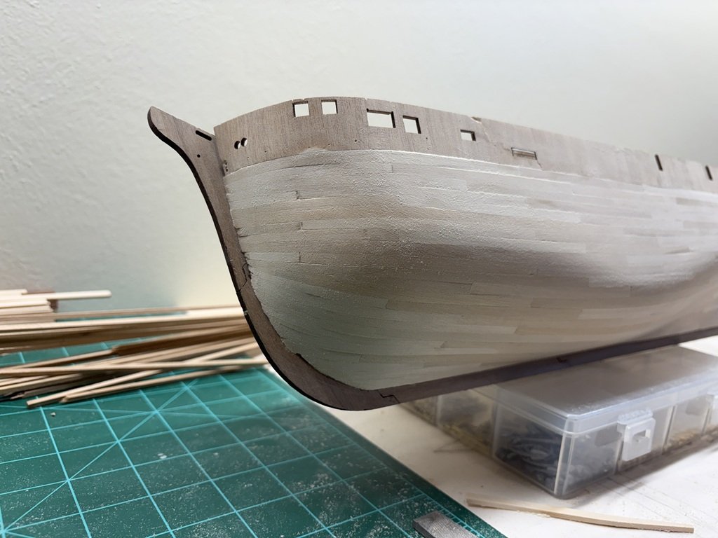
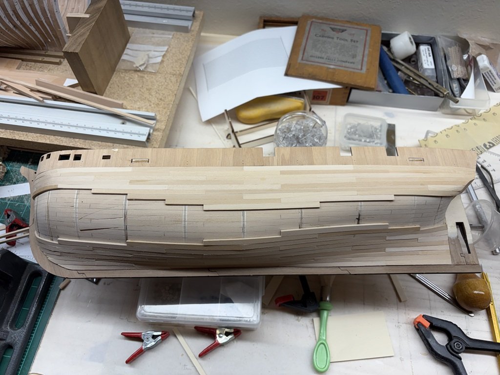
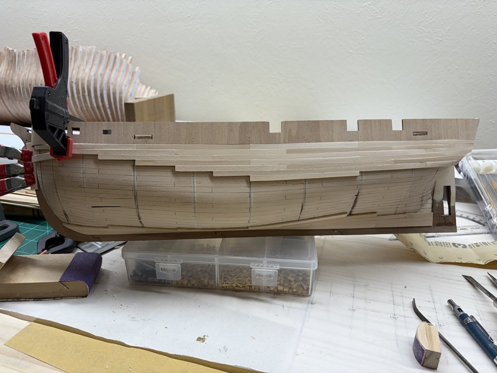
I (minor) milestone - the top and bottom planking work has come together!

-
Greg Davis reacted to a post in a topic:
HMS Terror by Greg Davis - OcCre - 1:75 scale
-
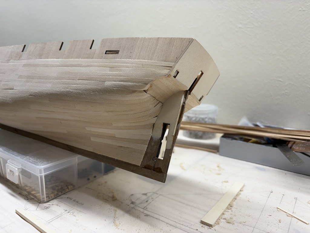
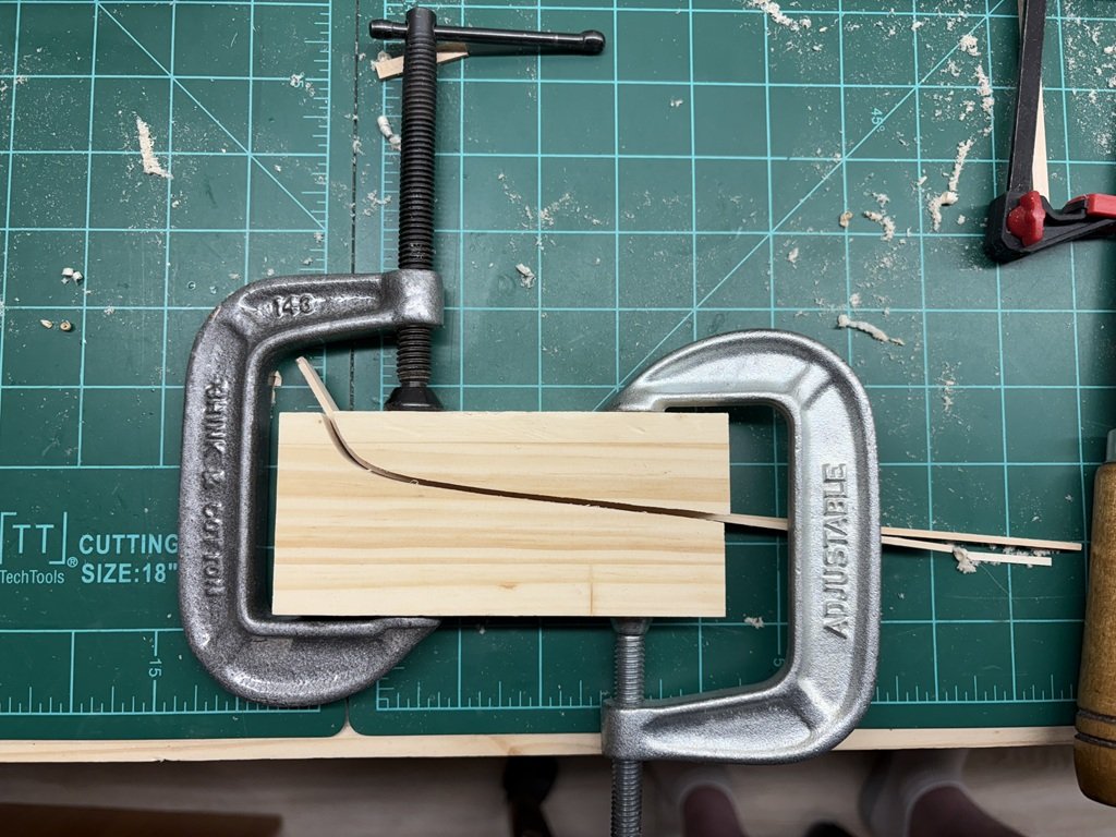
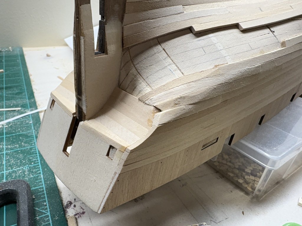
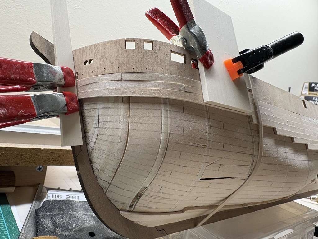
Progress - slow, but sure! One more plank and the top-to-down will meet bottom-to-top work. The plank sitting below the model has been bent in a jig to help facilitate the stern tuck planking. The jig is pretty simple; but, depending on the piece of wood, my take more than one wetting and overnight clamping iteration. The jig is very much like the one Chapelle uses to bend wales in his Ships of the American Revolution book. Here's the beginning of the tuck planking being installed:
-
The planking continues! Soon the middle gap will close. I've made a jig to help form the sharply bent stern planks - if it works, I'll post a picture of the jig.
-
Greg Davis reacted to a post in a topic:
Santos Dumont 14 bis (1906) by Greg Davis - FINISHED - Model Airways - 1:16 scale
-
Greg Davis reacted to a post in a topic:
Santos Dumont 14 bis (1906) by Greg Davis - FINISHED - Model Airways - 1:16 scale
-
Even more so when I have a bottle of this in the house:

-
A bit of progress - not as much as I had hoped for; however, I've spent a good deal of time over the past week creating a PowerPoint presentation on building model ships that will be delivered to an audience in the Learning in Retirement Program at the University of Wisconsin - Green Bay. Hopefully the talk will encourage a few to take up the hobby! Anyway, here is Terror as of this evening: Four planks are being pre-bent to take up positions near the stem and stern (top and bottom). Not too long before the top and bottom work come together! But still a lot of planks that need sharp bends. The Jameson is helping the process!
-
Yes I do, but I don’t tend to use it as much as I could! For these planks I’ve been experimenting with water and a hairdryer in a manner similar to that described in Chuck’s Chearful instructions chapter 4.
-
So far only 3 planks today ☹️. But they were hard ones that butt up against the stem. I needed to partially form each, then wet to bend, and do some more shaping before they could be attached. Once the now clamped plank dries I will be able to add quite a few planks with less difficulty going front to back and downward. Yesterday I got about 10 planks attached and cleaned up the back edge of the top 6 stakes. In the back, it is time to work on the tuck. There is quite a bit of bend in that area and I am debating the wisdom of creating a mold to bend the planks in that area.
-
Good to hear that the paint is of good quality. I agree, they are not great with instructions; either written nor with their photo collages. The builder really needs to continue to look at the pictures throughout the sheets of paper and determine a course of action. Certainly it is clear that some construction must come before others, but in some cases the builder must make adjustments and / or choices (best guesses) as they proceed. It doesn't seem that it should be that difficult for each and every model company to produce a solid set of instructions that are straightforward to follow. Its not even a question of language - I don't see that those that read Spanish would be any better off with the Occre instructions! Either way, I still think you are making very good progress with the model.
-
Thank you very much!
-
Good to hear the parts go together nicely! Yes, please start a log as it would be great to see your progress. The Lumber Schooner looks to be a really nice topic as well. I did buy the RC equipment along with the kit, but I'm not sure if I will use it or not. I'll PM you when / if I get to building the machine and start a log. Greg
-
I'm sorry to have been so slow to respond - I used medium CA to glue the engine castings together. Fresh CA worked well for me, but I've found that if the CA is old it is iffy in terms of the adhesion you may get. In a number of places I did need to file the castings so that the joint locations were tight to one another.