MORE HANDBOOKS ARE ON THEIR WAY! We will let you know when they get here.
×

FreekS
-
Posts
216 -
Joined
-
Last visited
Content Type
Profiles
Forums
Gallery
Events
Everything posted by FreekS
-
Wow, that ladder would be a nightmare to solder for me - and the precision!! Were all rungs soldered at the same time?
-
Looks very nice! One of my club members has a sound module that includes the engine (of a MTB) starting and the sound rising with speed. Very impressive. I’m still contemplating what kind of sounds I could use in my submarines!
-
Great method to seal the sides of the masking tape! Thanks!
- 375 replies
-
- 3
-

-
- minesweeper
- Cape
- (and 1 more)
-
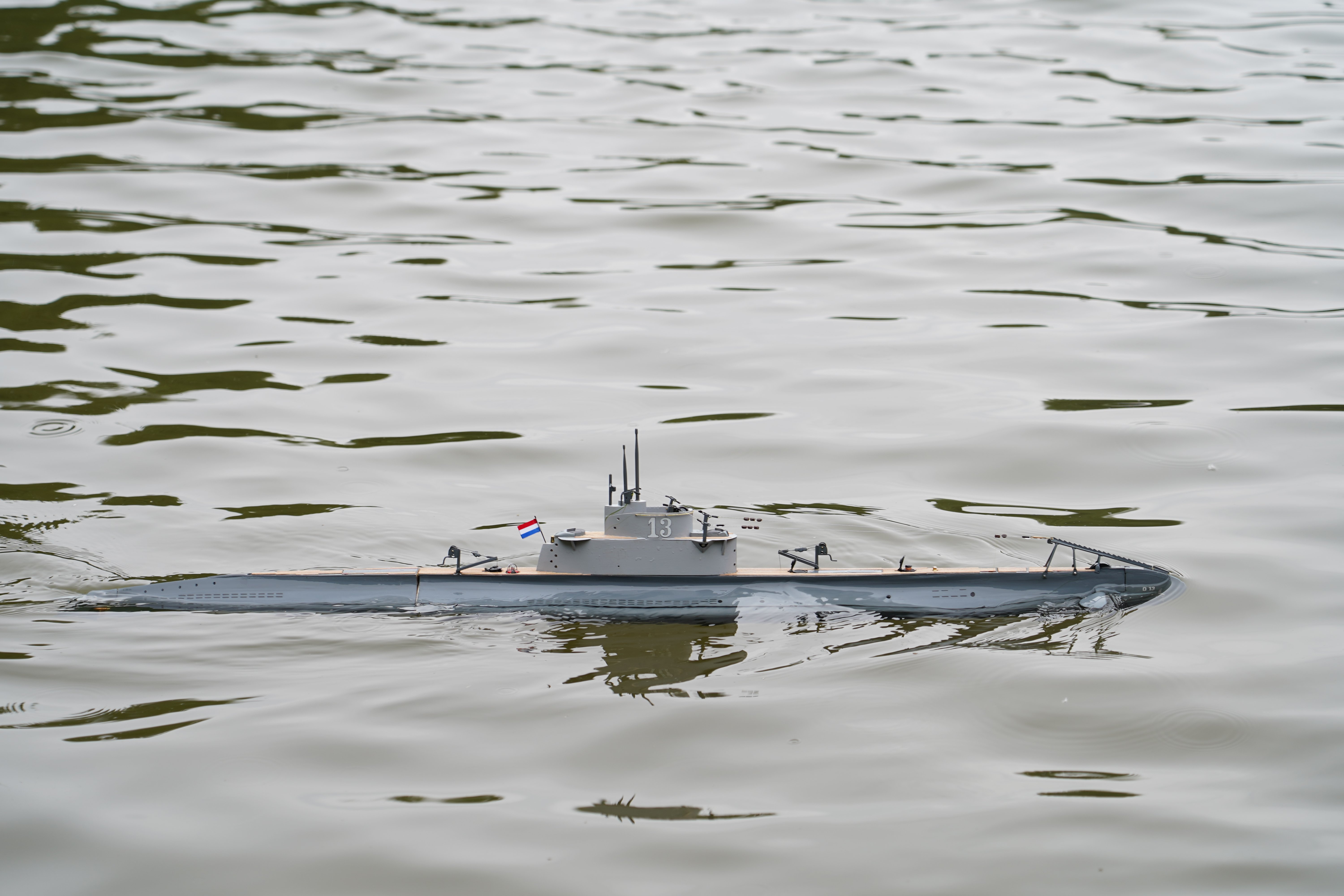
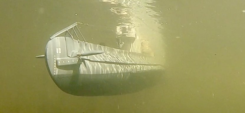
Video O-13 here is a boring 2 min video (on YouTube) showing O-13 in the not so clear water of my model sailing club. It’s doing some nice slow rounds!
-
Another thing to watch for is time delay between “forward” and “reverse”. Car models have this, ship models should NOT and it’s often a programmable property of the ESC.
-
I thought that was a coffee mug until I zoomed in!
-
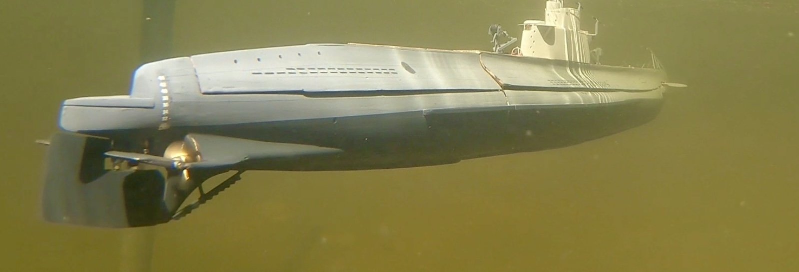
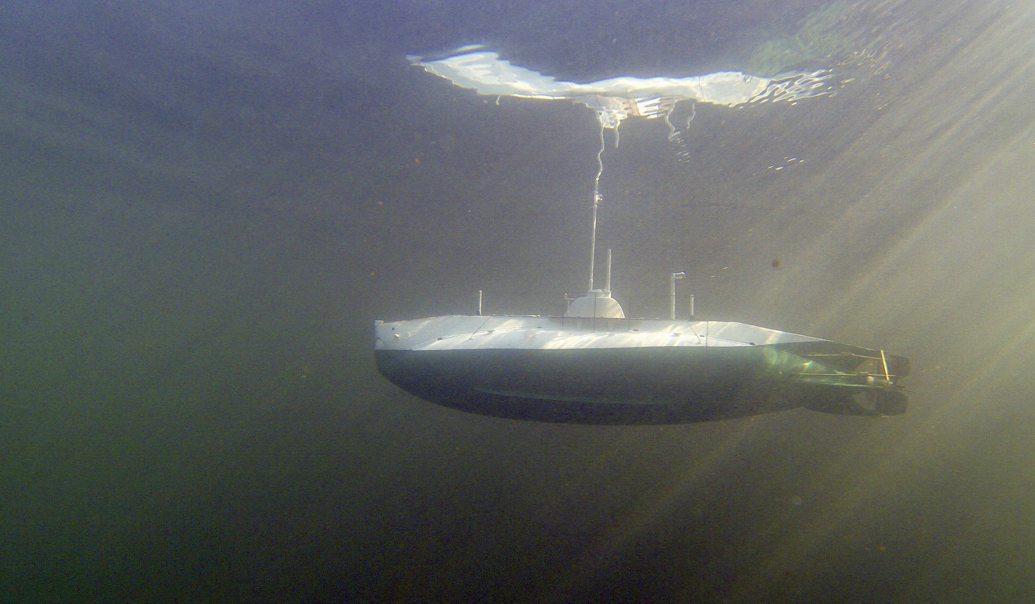
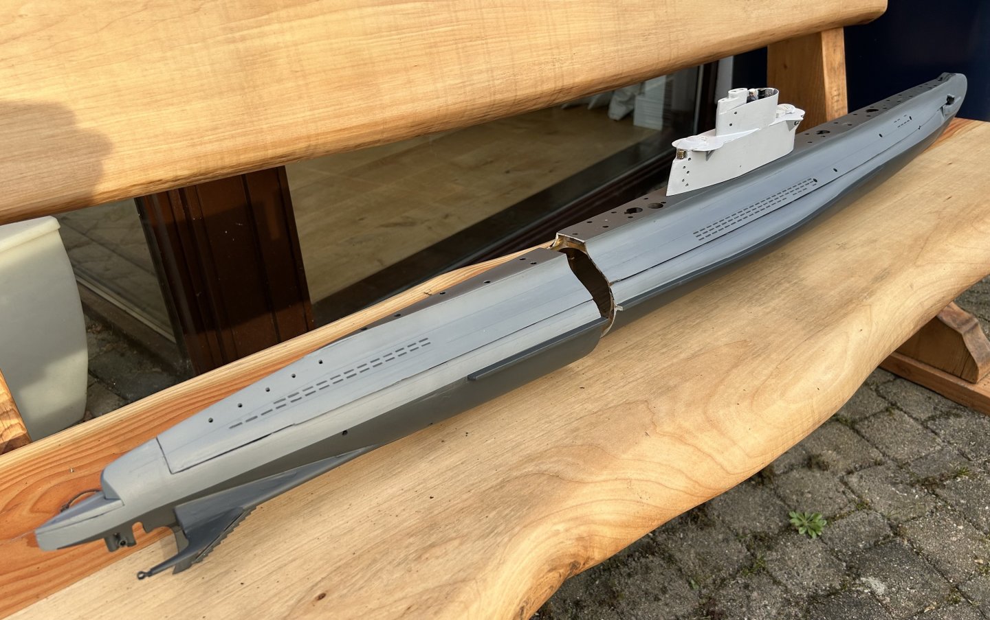
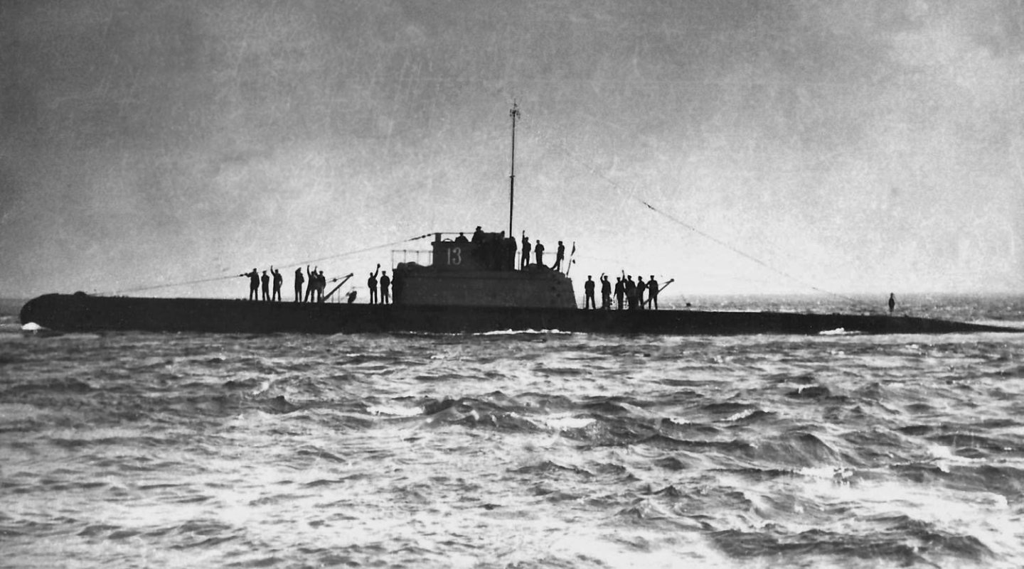
Both boats in this pic operate close to their scaled max depth, for O-13 around 60 meter (one boat length) and skipjack likely over 200m. It’s also amazing to realise “only” 25 years separate building these two subs!
-
It will be a real challenge to realistically model that smoke!
- 448 replies
-
- 2
-

-
- sternwheeler
- Hard Coal Navy
- (and 1 more)
-
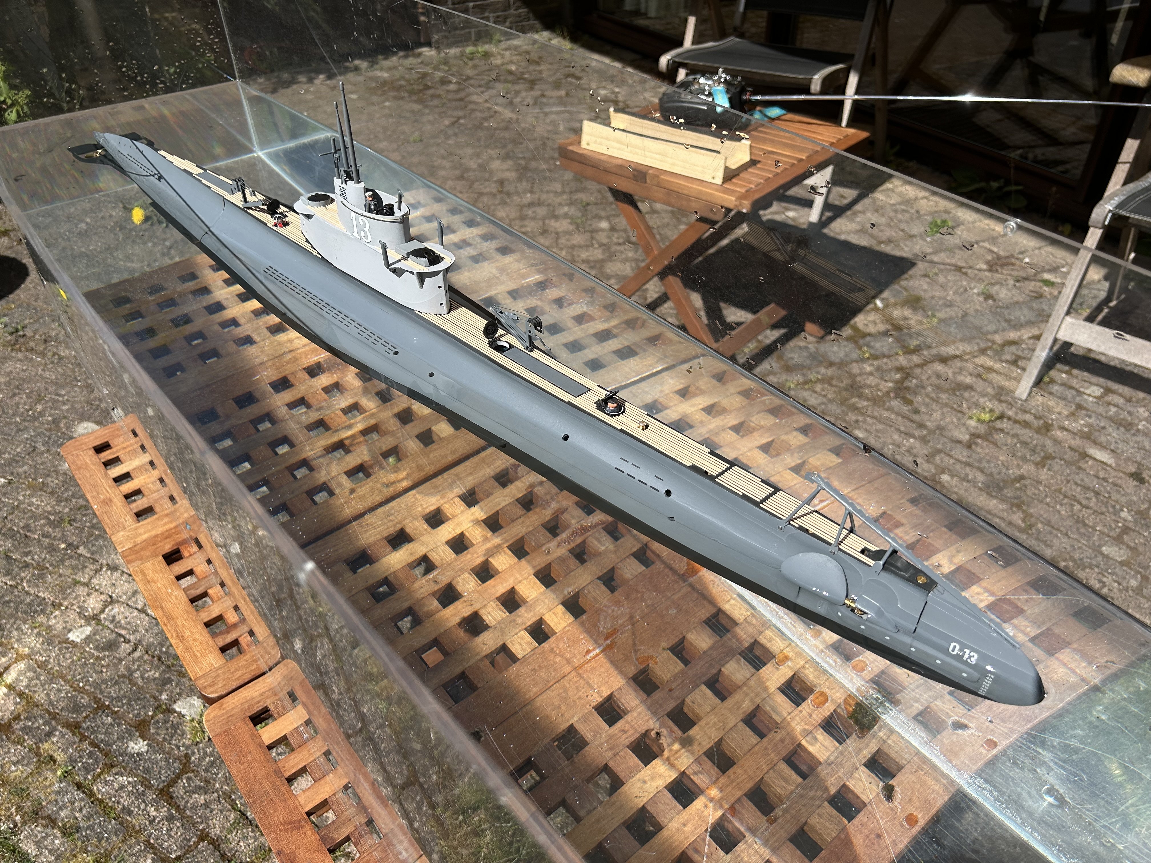
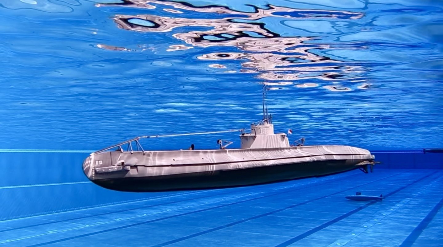
I’ve made the first international trip with O-13, to Nürnberg in South of Germany where there was a big submarine meet in a pool. Hung a GoPro over the Edge of the basin and spend two days sailing. Done quite a lot of optimising ballast, tweaking the movement of the front diveplanes and much more. Also replaced the props with nylon/carbon 3D printed ones with much smaller pitch, to sail slowly enough at periscope depth. And found room to install an automatic leveler. Now the boat is near stable at periscope depth with the rear planes being controlled by the leveler and both front and rear planes also by the transmitter.
- 97 replies
-
- 10
-
-

-
Piets O-19 was very nice. We exchanged some details drawings at the time - I was building O-1. I’ve not heard from him in a long time ….
-
Thanks mcb! it does add to the enjoyment of building, but building subs seems to me to be less risky than planes or helos. With subs, the main risk is losing sight of it when it’s submerged. That really raises the heartrate! As long as the boat is well waterproof (and possibly with a water in the boat alarm), the consequence of a problem is that the boat will fall still, sit on the bottom or float. At least it won’t crash!! Mostly I sail at a sailing club where when needed there is a boat, a wading suit or even fishing gear to go look for a lost sub. The key is to always keep your eyes on the periscope! but yes, the risk is part of the fun….
-
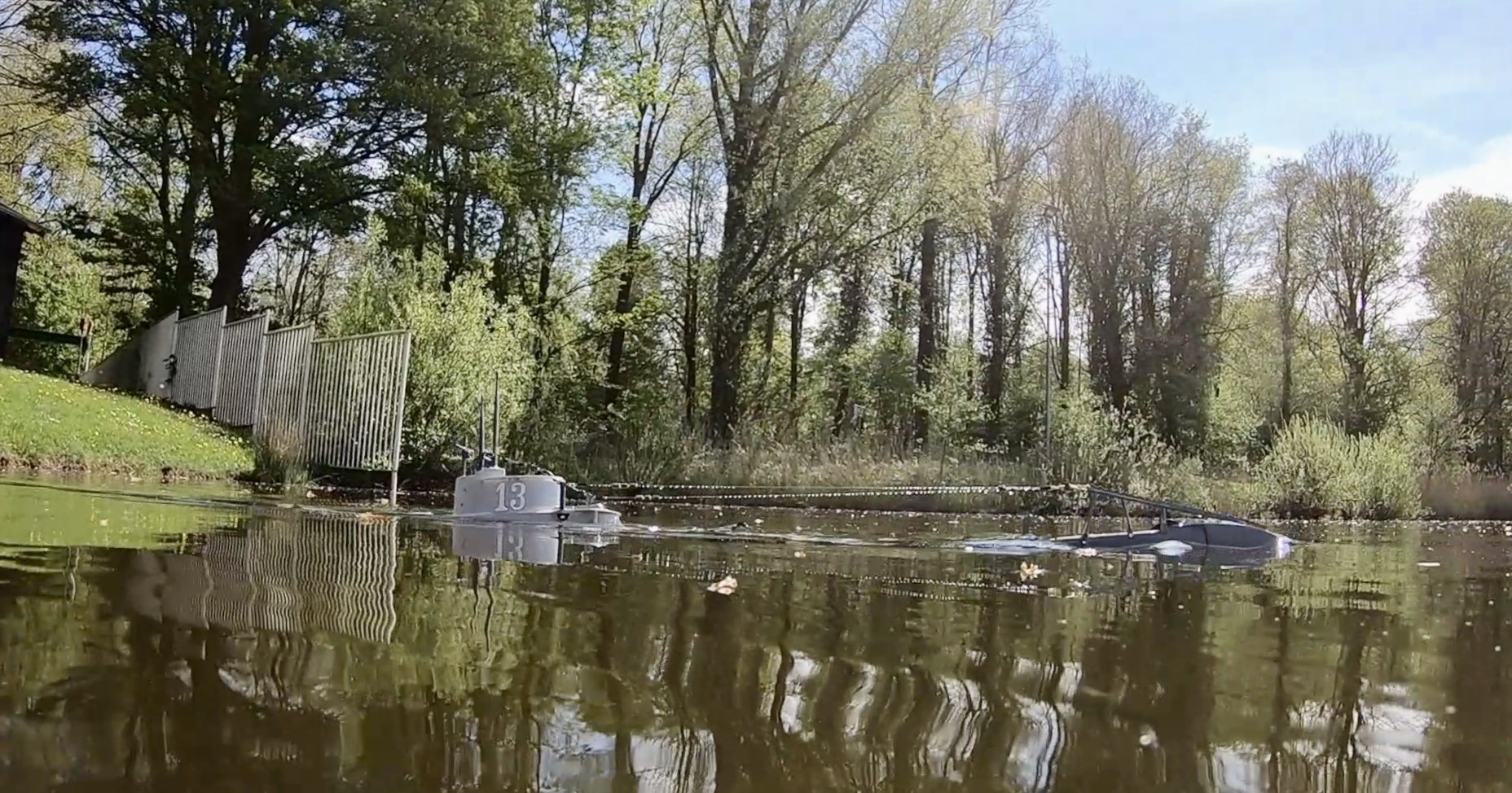
The “leak” turned out to be an “error in thinking”, water dripped out of the flood zones, not the watertight compartment! Decals replaced and in clear coated with a brush (instead of airbrush) hopefully has a thicker protective coating. The boat was a bit heavy after so put a bit of floating foam under the deck. then today we went with a small group to my model sailing club. Sunny weather, about 1-3 feet of pretty clear water, could not be better. amd the boat sailed - a bit too fast, very easy to dive and surface and a huge turning radius. Still work to be done, but the boat is fully under control and I’m very happy!


- 97 replies
-
- 11
-
-
-
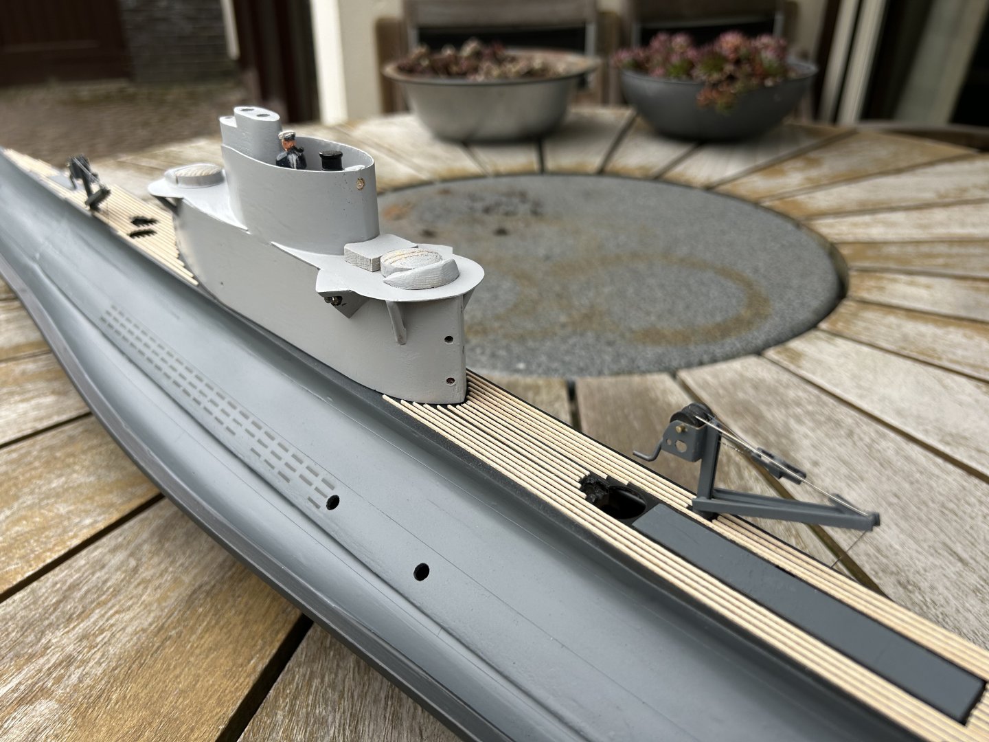
Yes it is difficult, frequently I have to reach and change a component worked on months ago that is no longer so accessible. Now that the cranes and net cutter are mounted on the deck, I needed to make a rig to safely work on the components under the deck section, for fear of damage. But pre-thinking those things is also part of the fun…
-
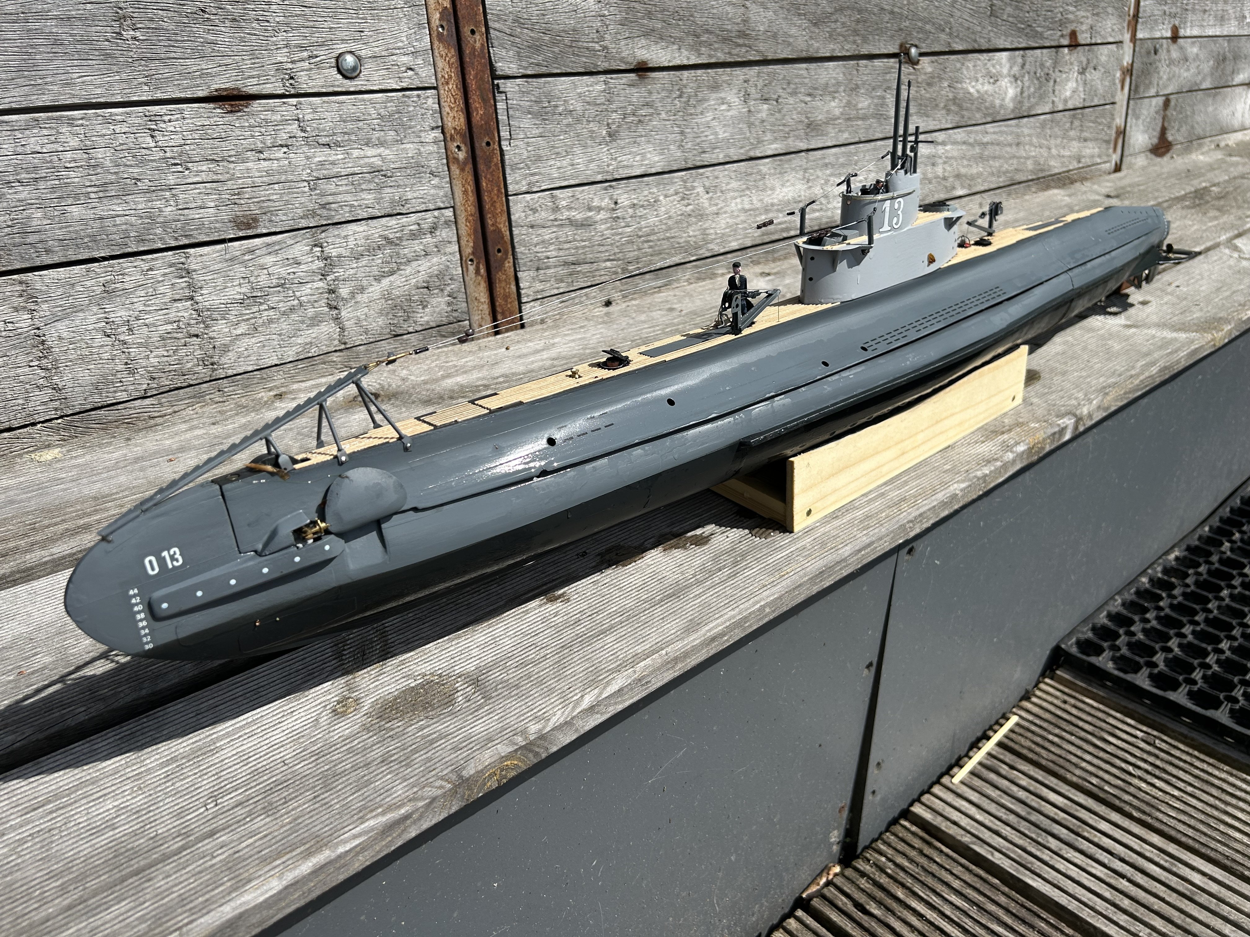
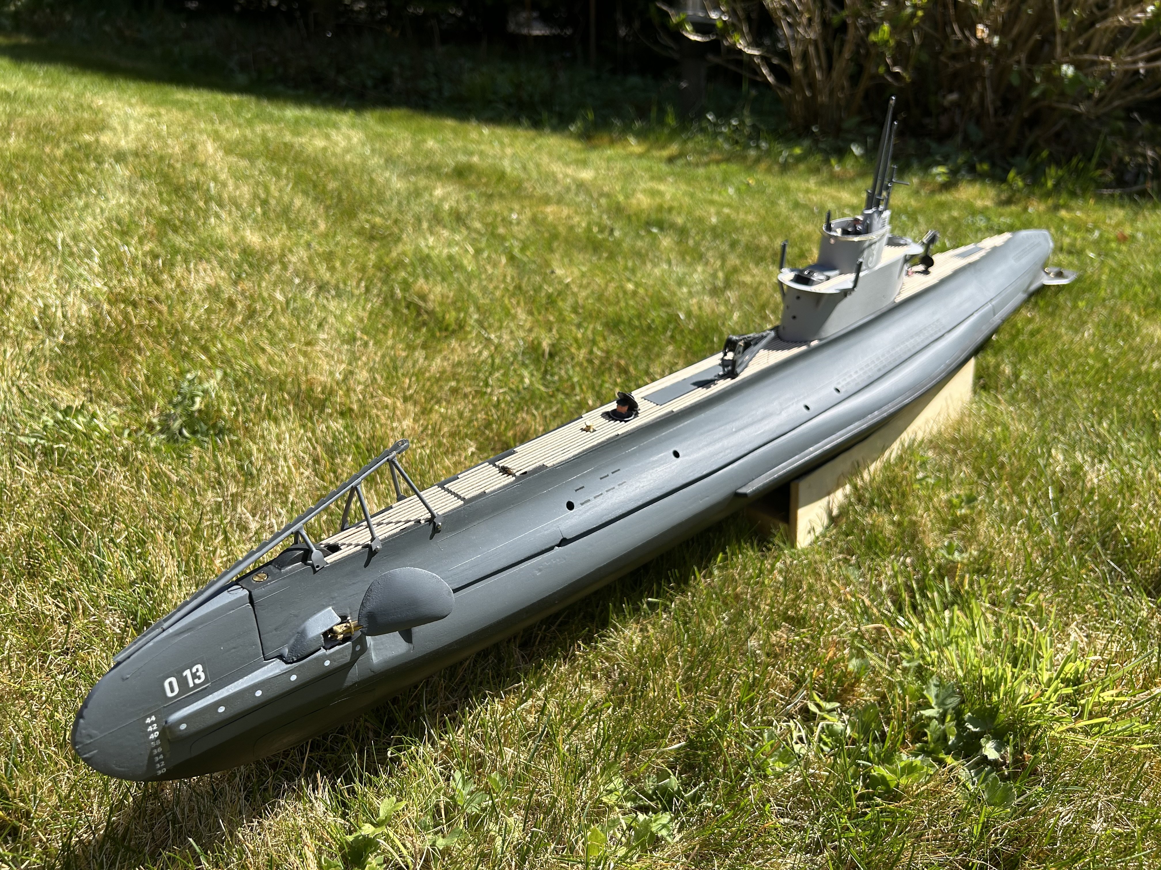
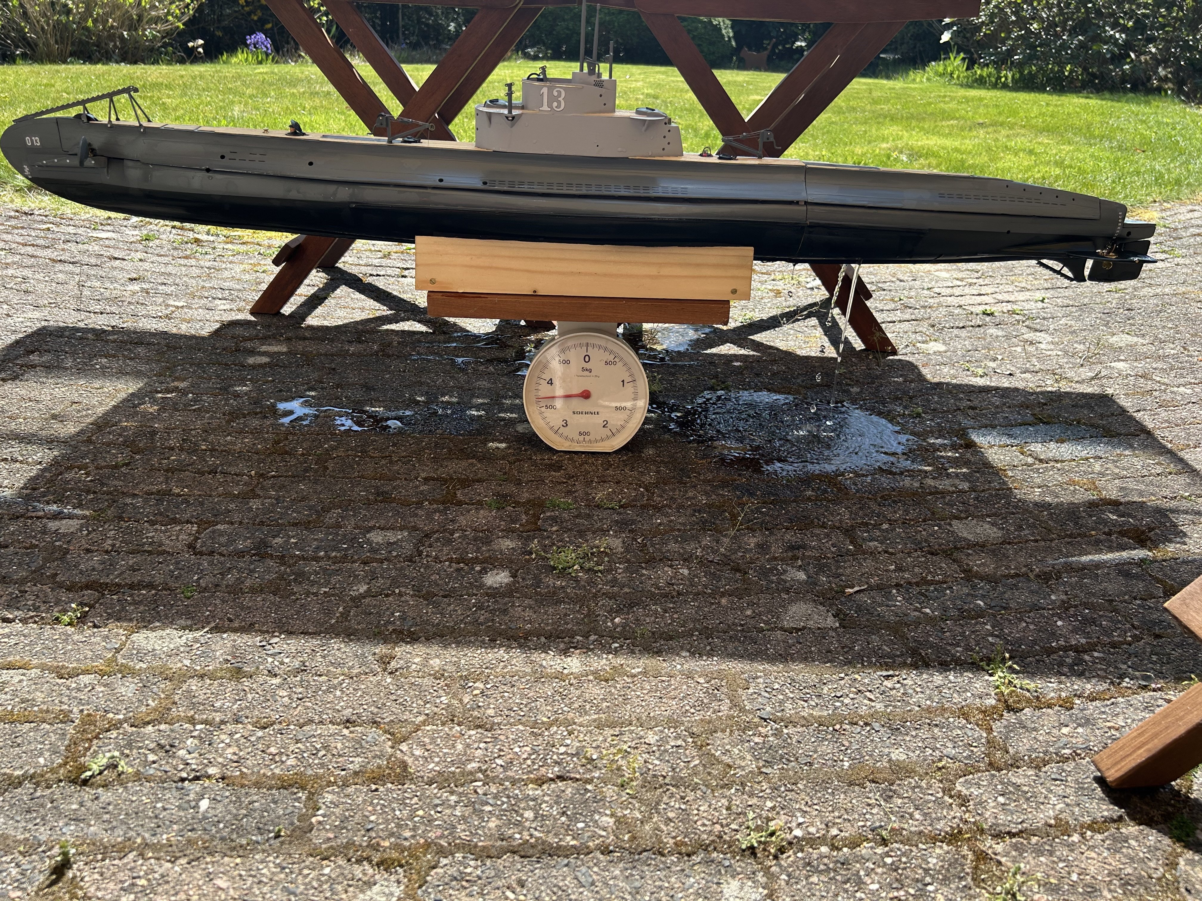
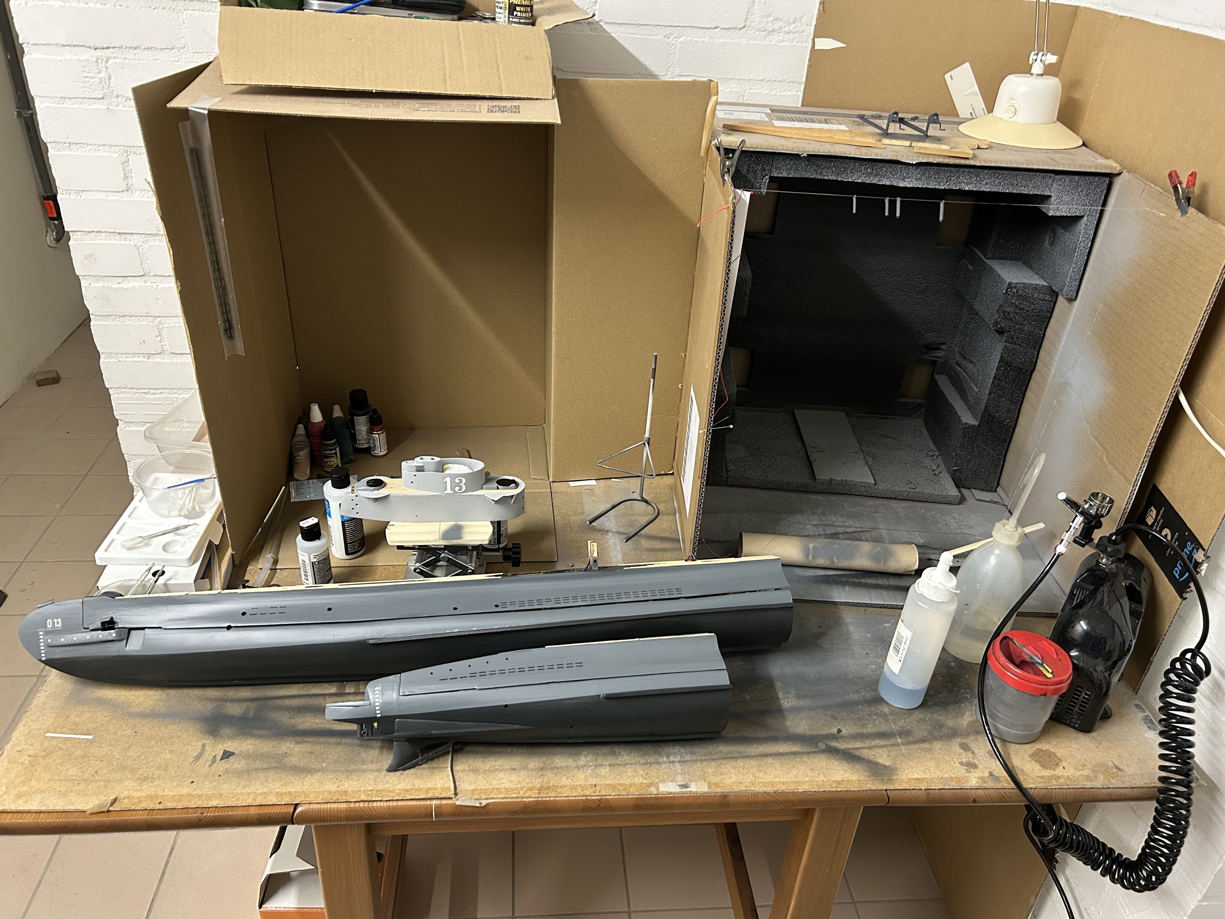
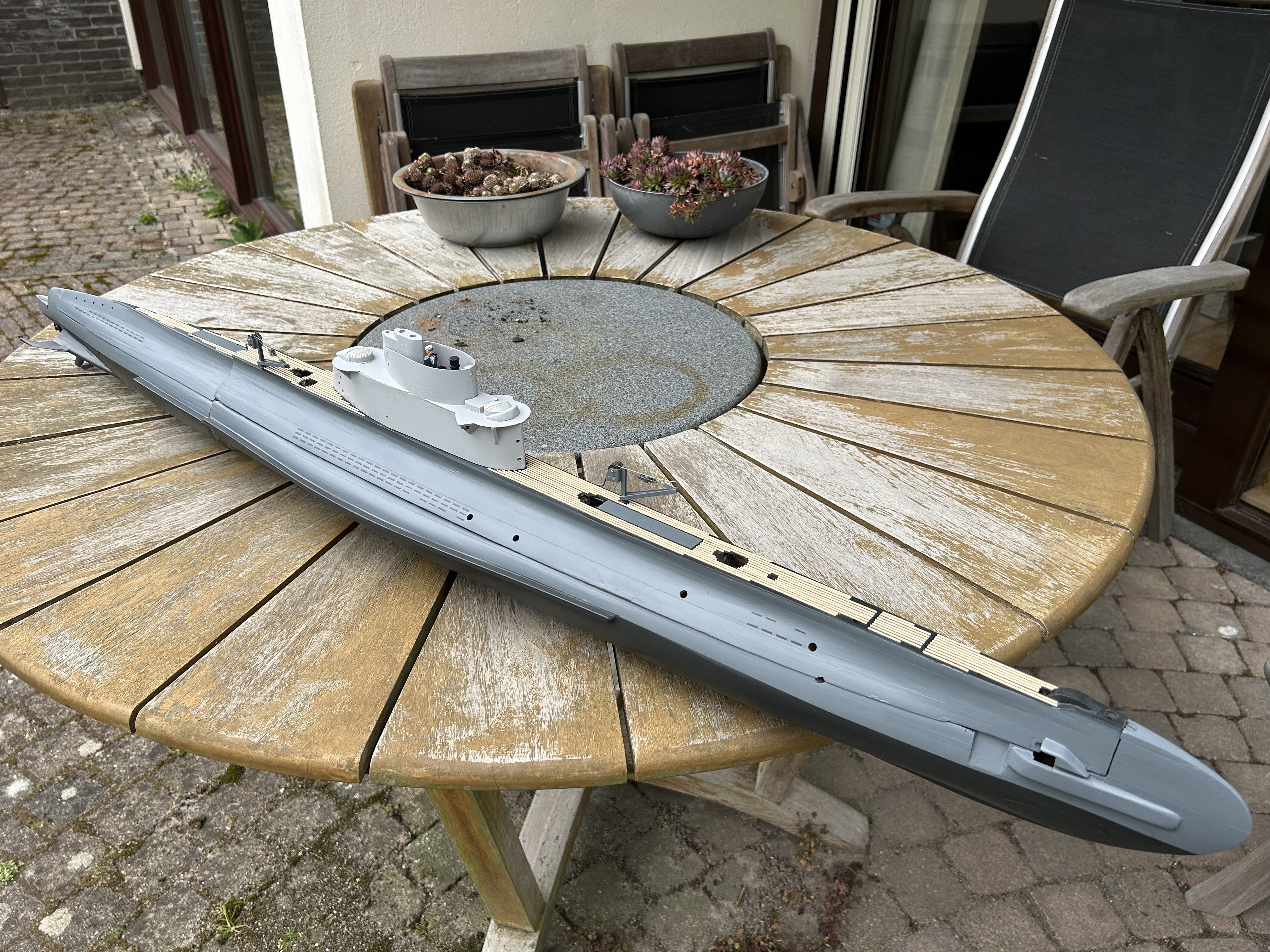
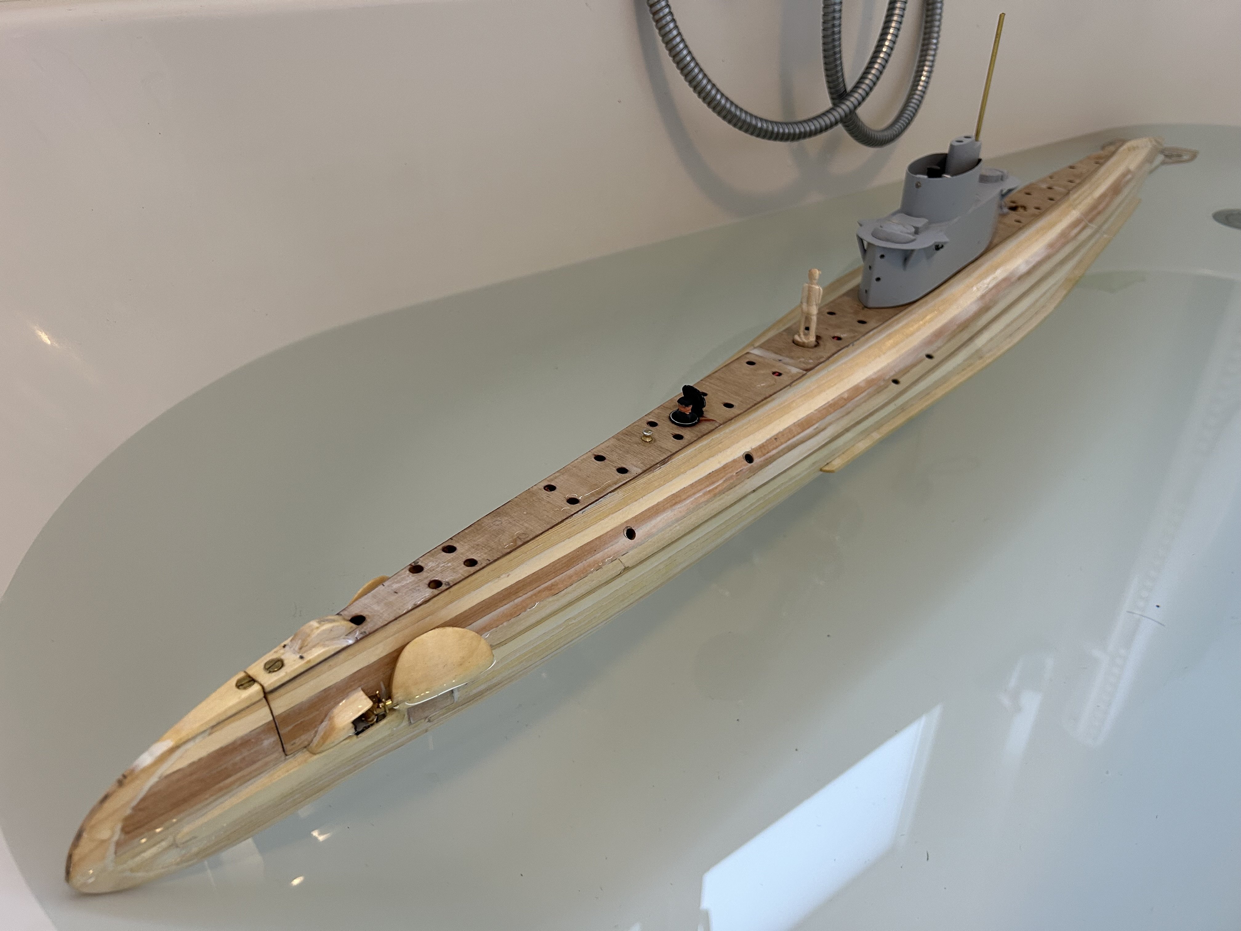
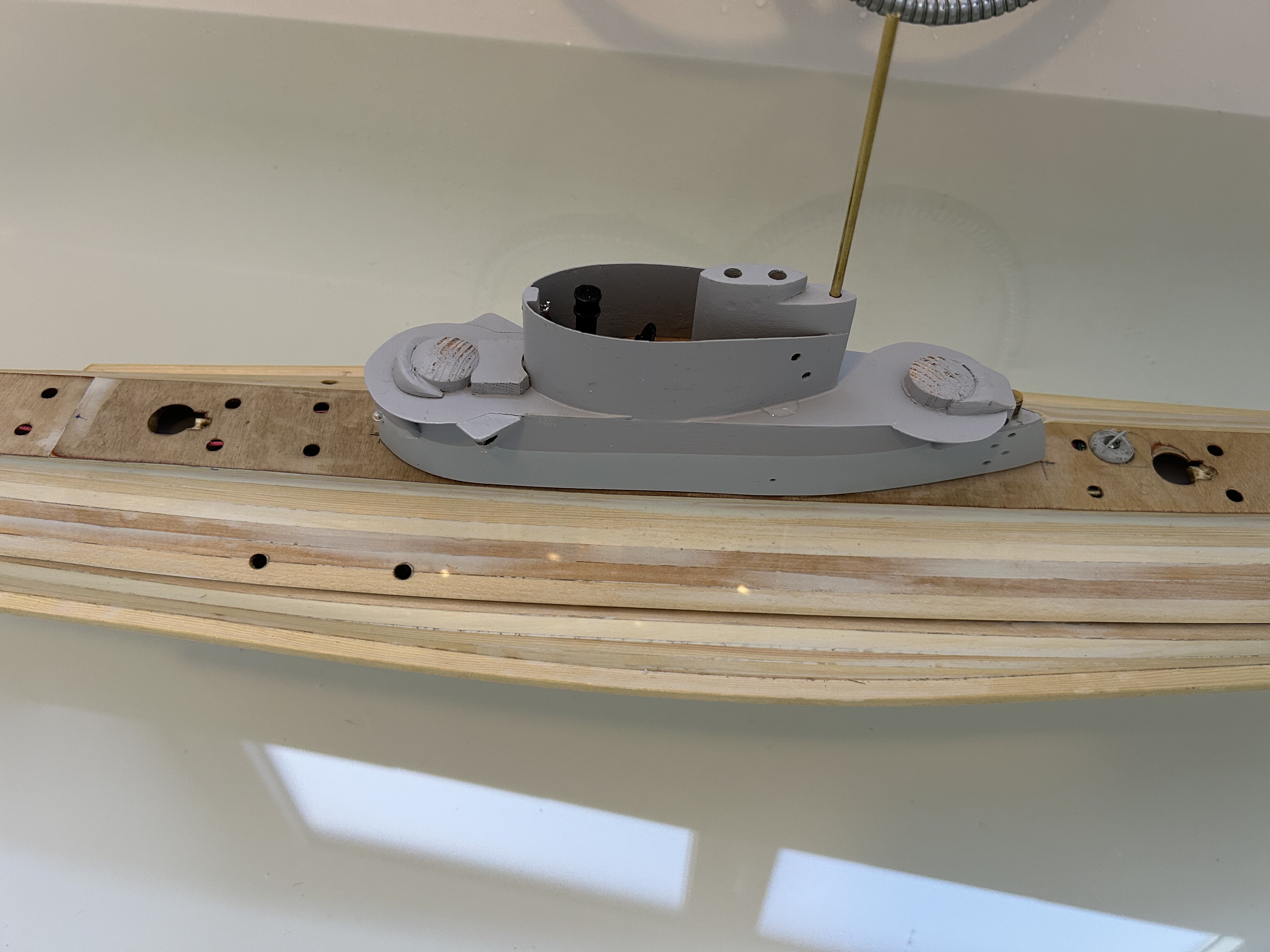
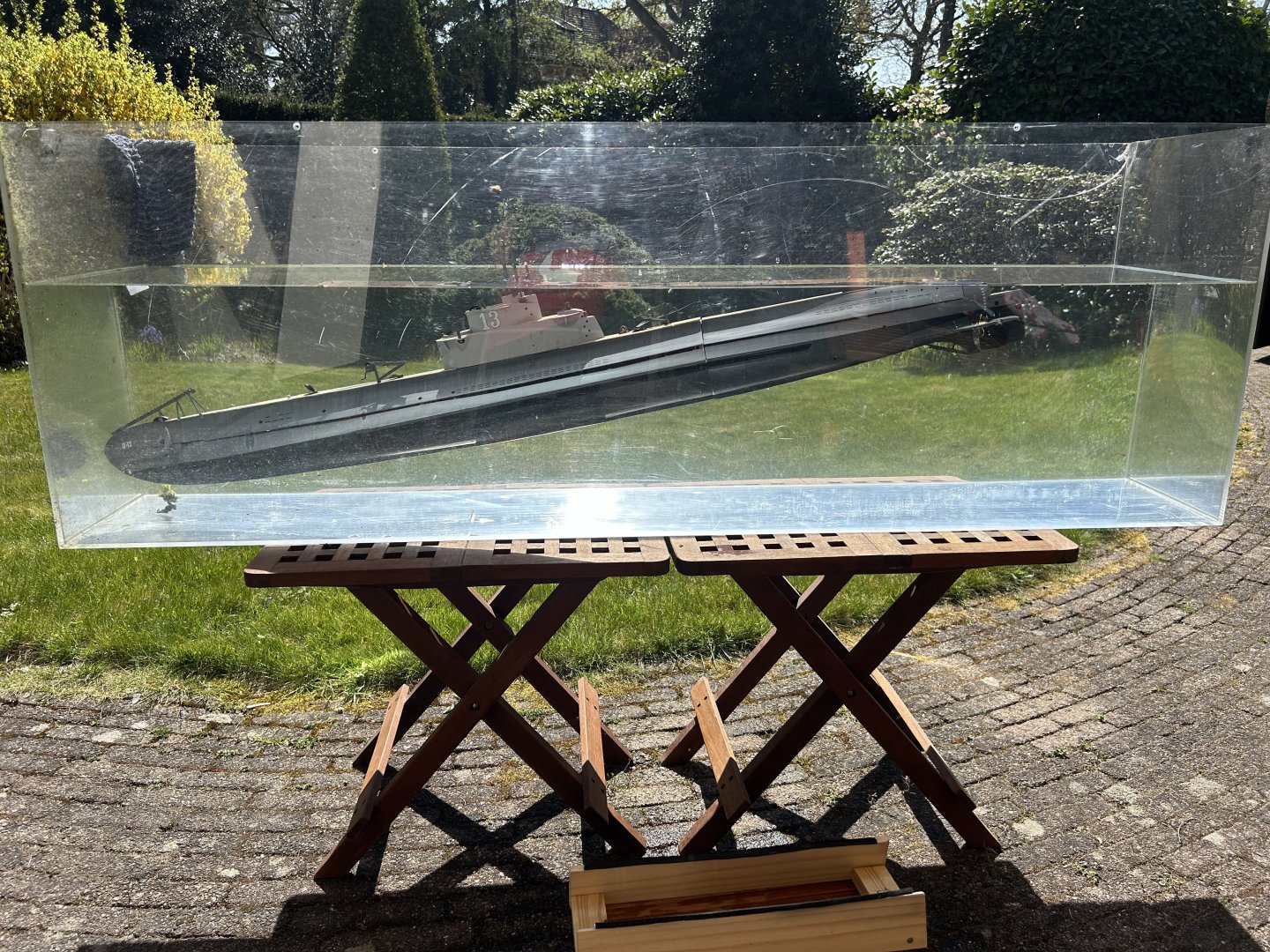
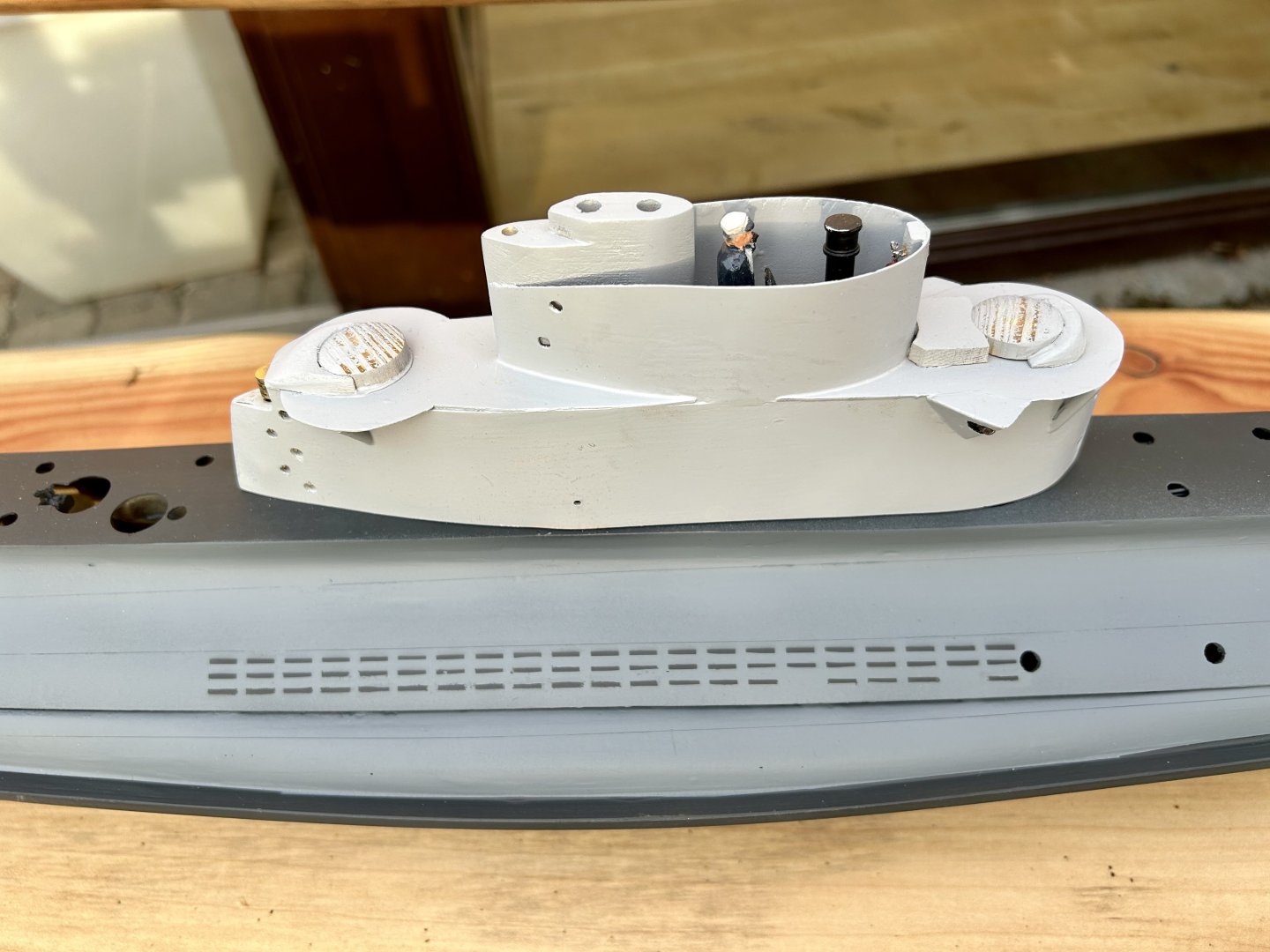
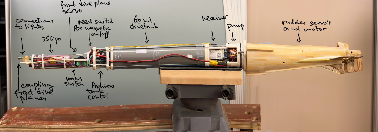
The past weeks were about making everything ready for balance tests in water following the rough trimming I had done in my bath and the one night sailing. For that I needed the weight (distribution) to be close to final. Ive painted and mounted the net cutter, turned two periscopes on my mini-lathe, made an aft mast that will double as the air exit from the tank, made the floats to close all 4 hatches when the boat dives, and mounted the bridge equipment (radio direction finder, compass and helm). Still some smaller details to do but the boat looks great! In my plexiglass test tank the boat lies level on the waterline. I would prefer a slightly higher nose-up attitude. Then started the pump to fill the tank. The pump is programmed to stop after 27seconds, which was enough to fill the tank in earlier “partial” tests. Now it brought the boat to “decks awash” but not to neutral buoyancy. Took the boat out, weighed it on a kitchen scale (3,9kg) and then emptied the tank (now 3,4kg). As the tank volume is 600ml the tank was clearly not full. Maybe the air exiting through the mast is giving some back pressure. On repeating this twice the boat came lower in the water (and more nose heavy). Now the boat with full tank was 4,1kg. Do I have a leak or did I fill the tank more? Took the boat out, there was a small amount of water in the water tight compartment (may 10-20ml), not enough to trigger to water sensors. Ok, it’s clear that I need to change the tank filling procedure (fill longer and end with a slow top up fill?) to try to get the tank totally full always. 100 gram more or less has a huge effect on the stability underwater. There is no point in adding or moving weights until the tank is always full. I have a list of other issues (find the leak, one decal came off for example), so my task list for the coming weeks is set - and that was what the testing was for! Thanks for your attention - this phase of fine tuning subs is always time consuming (and fun), and I’m very happy with the overall look of O-13!


-
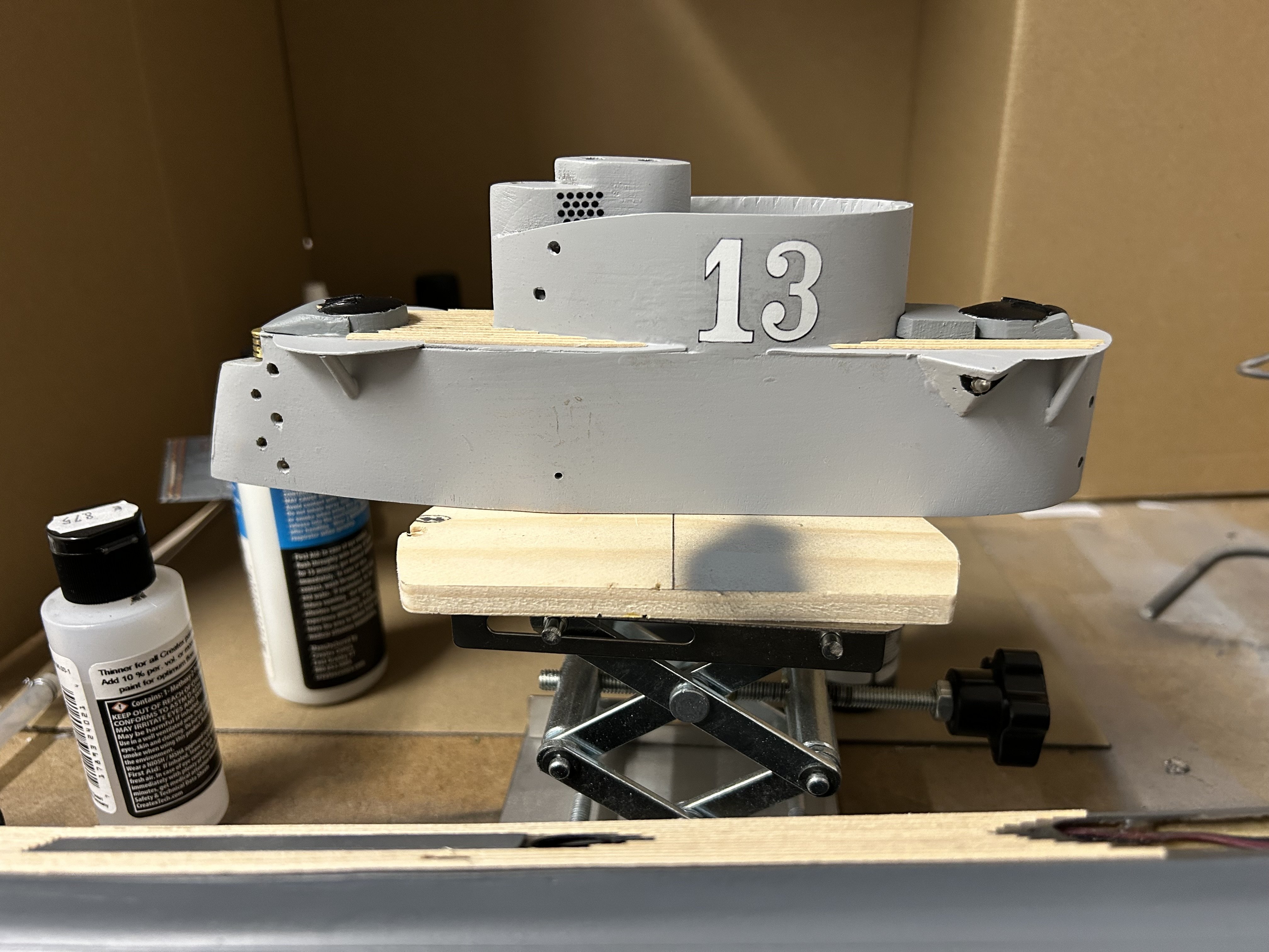
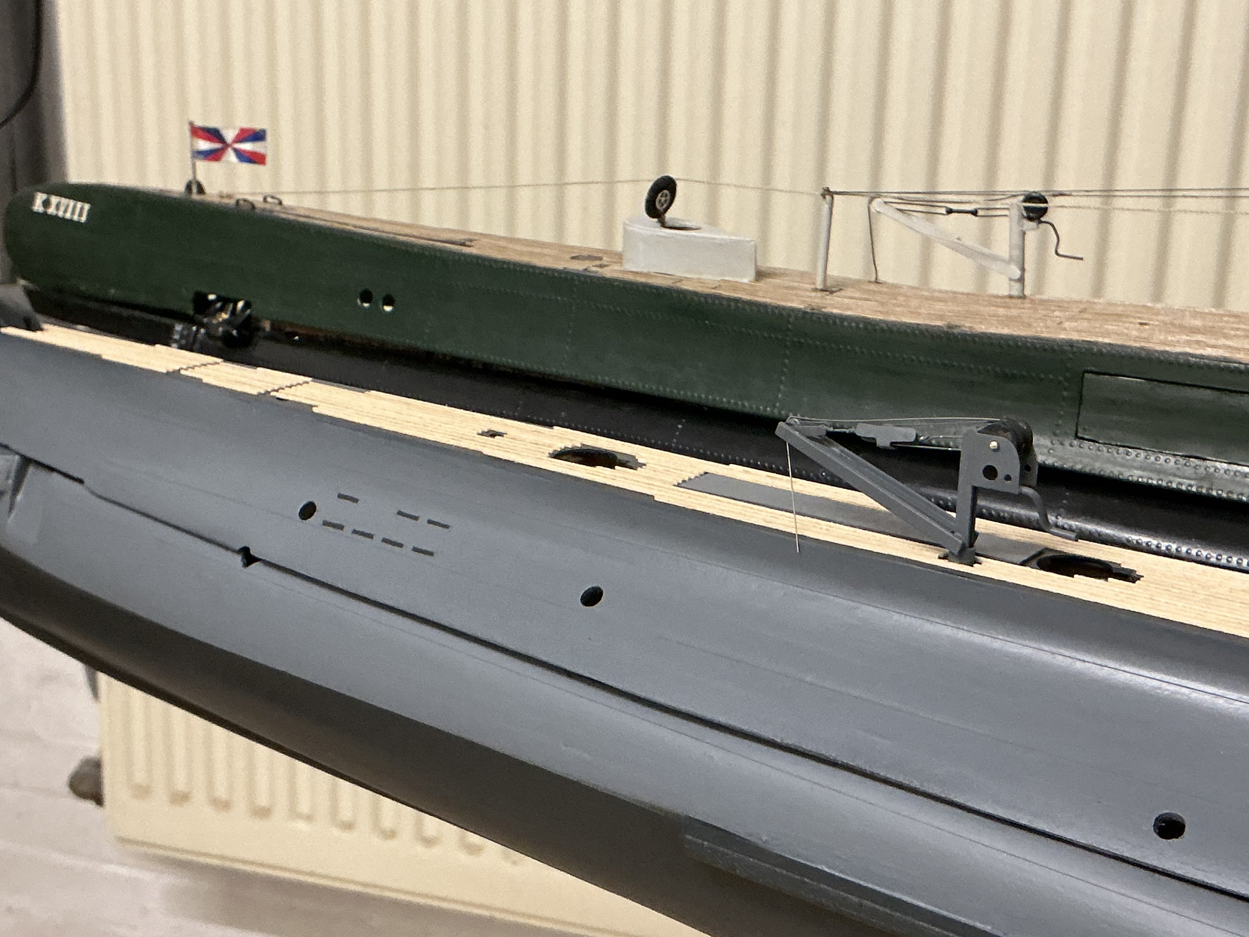
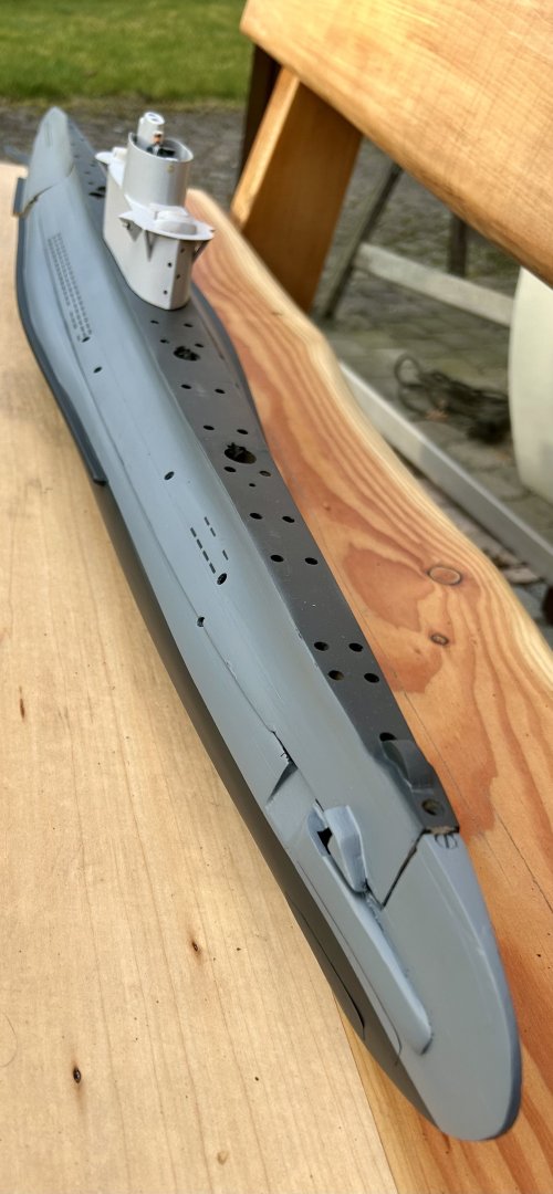
The cranes have been completed, the main cables are 0,3mm stainless steel which hopefully stays nicely straight over time. In the background the same cranes as I built them from wood twelve years ago on my K-XVIII model (after sailing 78times these still look good!). Also the wooden deck has been constructed from 1x1 mm wood bought at a rare model shop. A bit thick at this scale, but I don’t think I can sand it down nicely enough, so I’ll leave as is. For the moment covered by two layers of clearcoat, will add some more once the decals are mounted.


- 97 replies
-
- 11
-
-
-
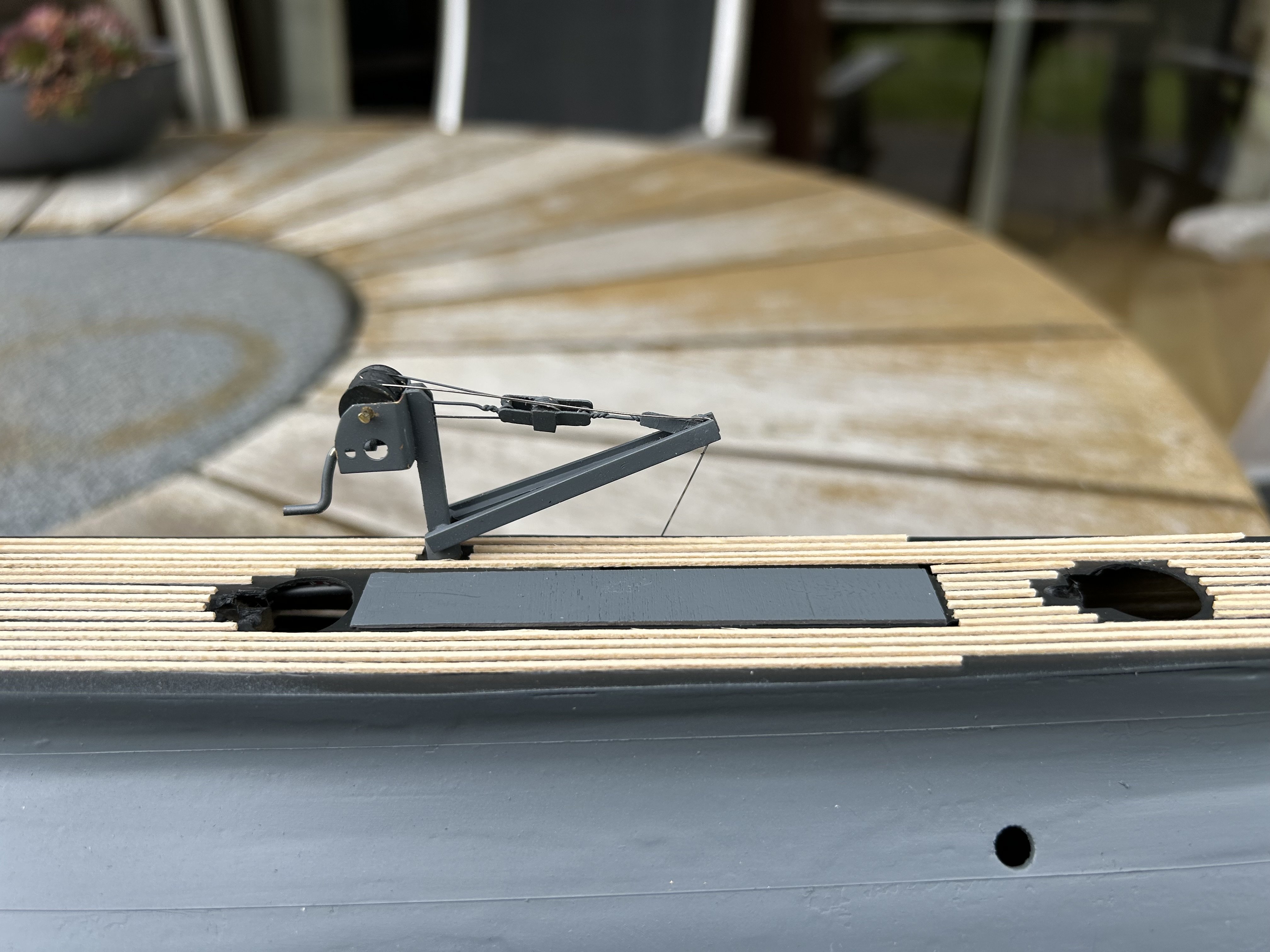
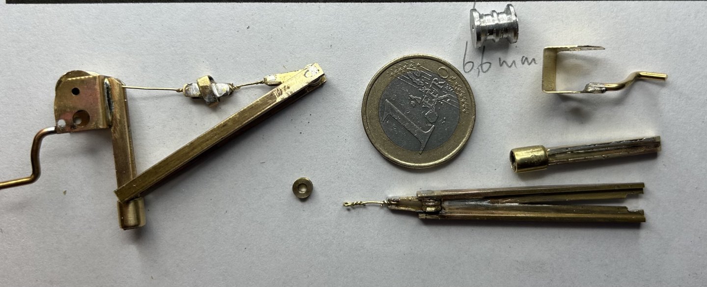
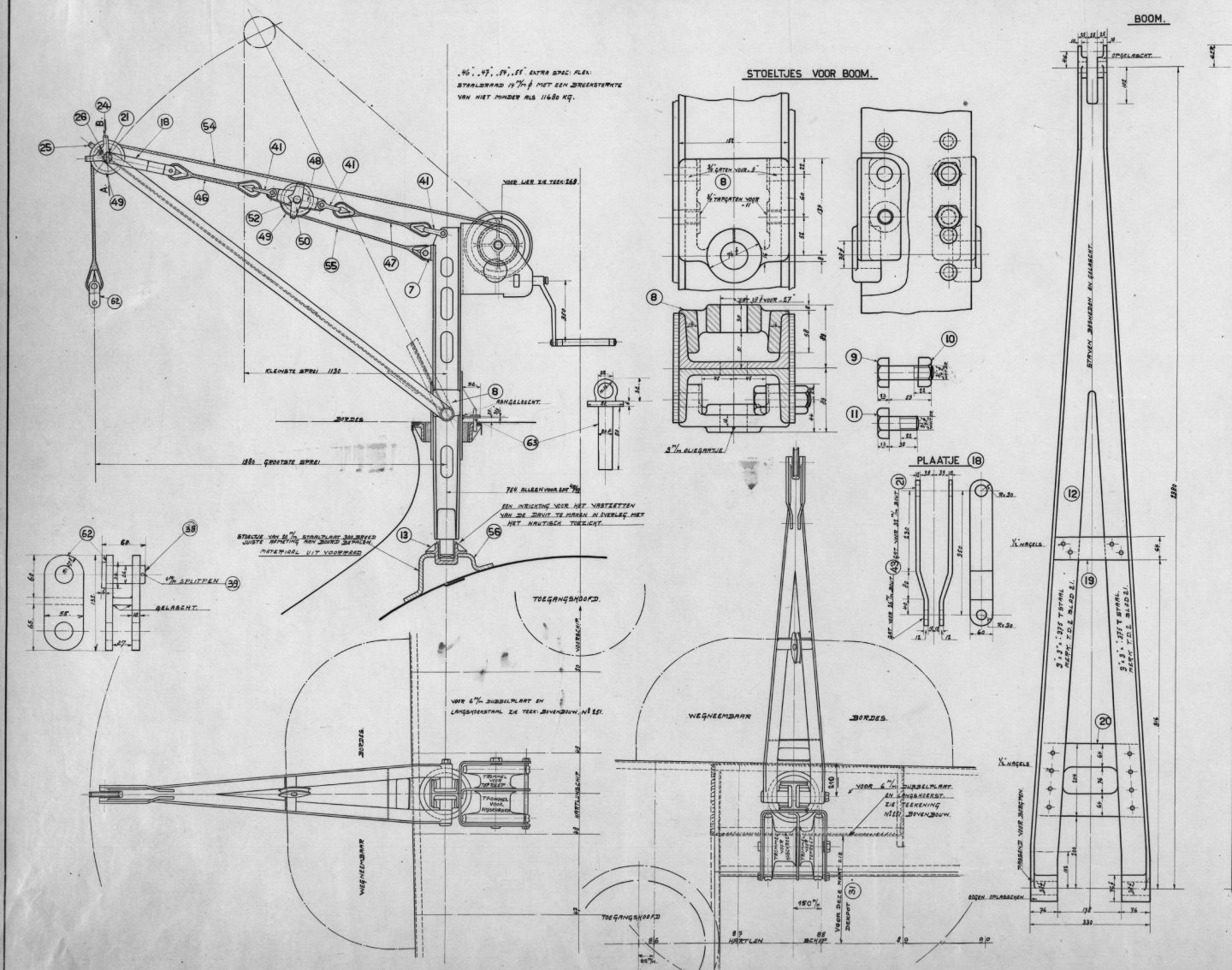
Today was a soldering day, I made the parts for the two cranes on deck. These were used to load torpedos and are permanent on deck. The drawing showed the main beams to be made of H-beams (for strength of course), and these were made at 3x3mm, seated in a 5mm brass tube that will anchor the crane in the deck. The torpedos weigh several tons, and the 14mm cable was rated for 11 tons. At 1:50 that was made from a 0,3mm brass wire. The double cabledrum was turned from 8mm brass and aluminium (brass was easier) and two blocks with 4mm wheels were made for each crane. Here is first loose assembly before painting and including the two actual cables (one for raising the crane and one for raising the torpedo).
-
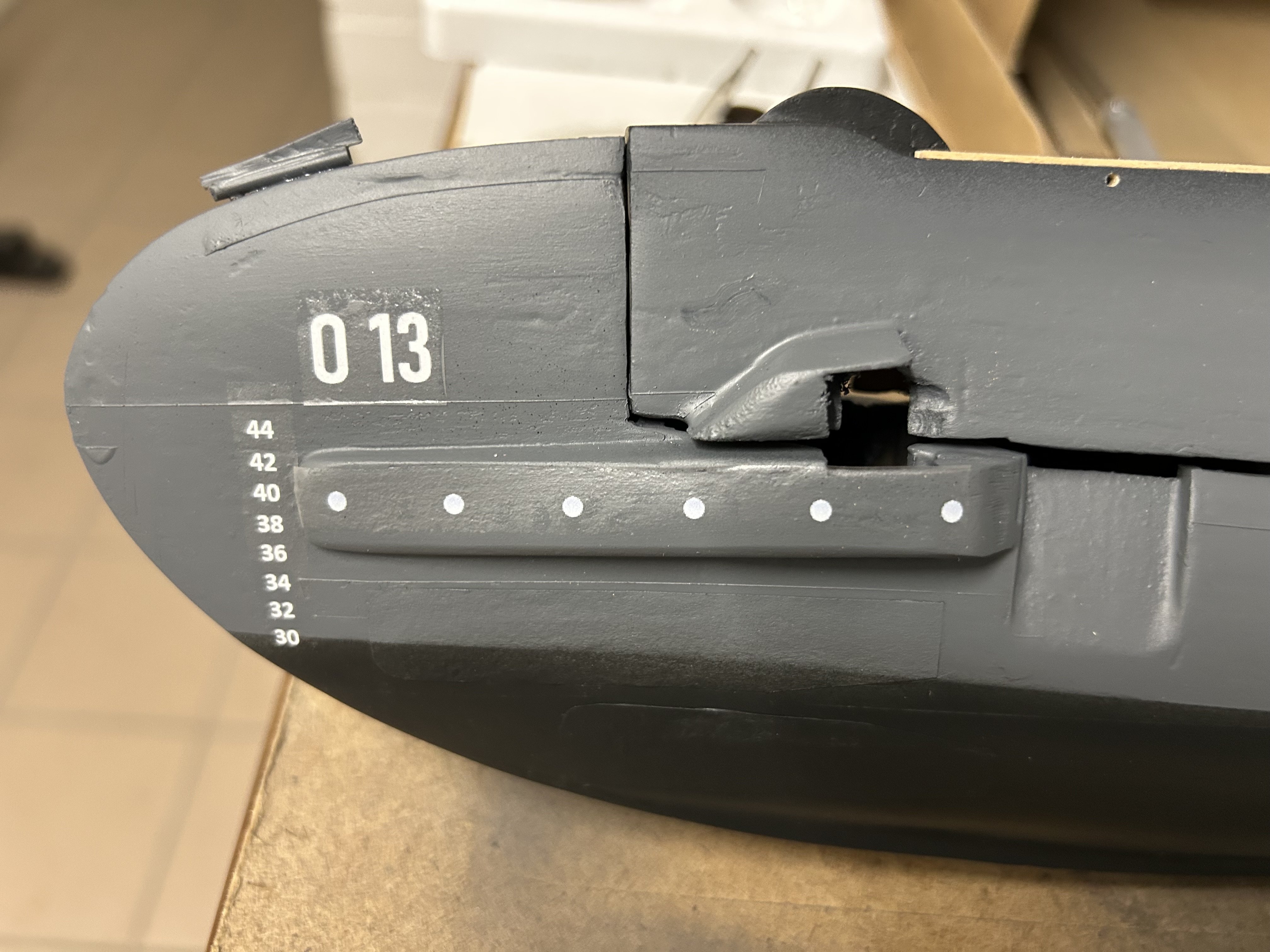
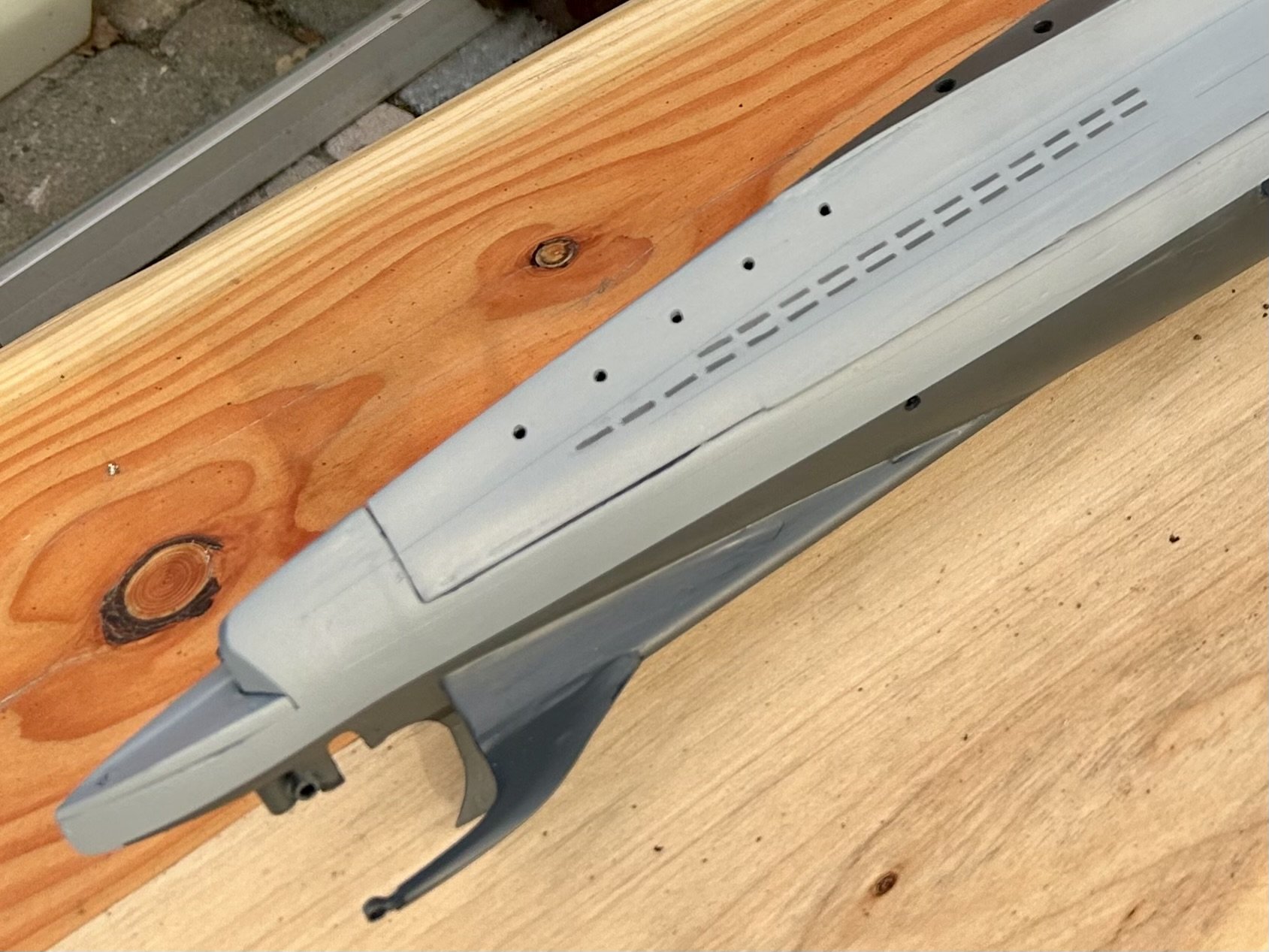
My model boat club organised a beginner airbrush course in February. I bought a starmax about 10 years ago but kept using brush mostly. For this boat I’ve been practicing… The sail was already painted with rattlecan , but I used the airbrush for primer and grey coats of the hull. Some of the horizontal deck plates are very visible on photos, so I tried to mimick those by marking them with tape and applying some paint with a brush about 4 mm above the tape. Then tape was removed and after another couple of airbrushed layers the plate was nicely visible. I also tried some rows 3Dprinted rivets (0,2mm on decal) on a testplate, but after airbrushing they were no longer visible. Photos do show rivets but I need some more testing to see if I can make them visible (and hide the decal film). dis make a stencil for the flood holes, that worked OK but needed some touchup.

-
Super detailed work and great photography!
-
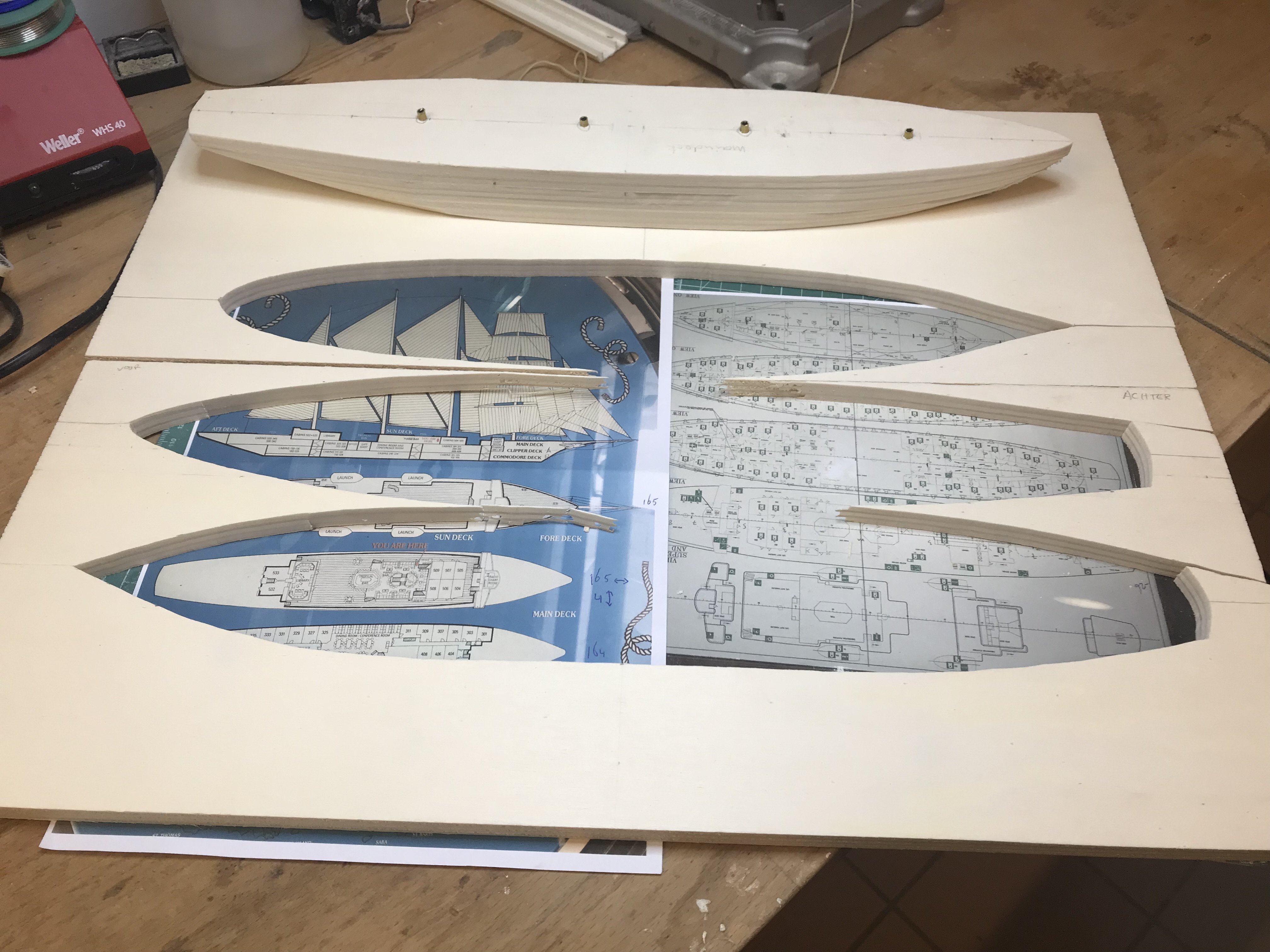
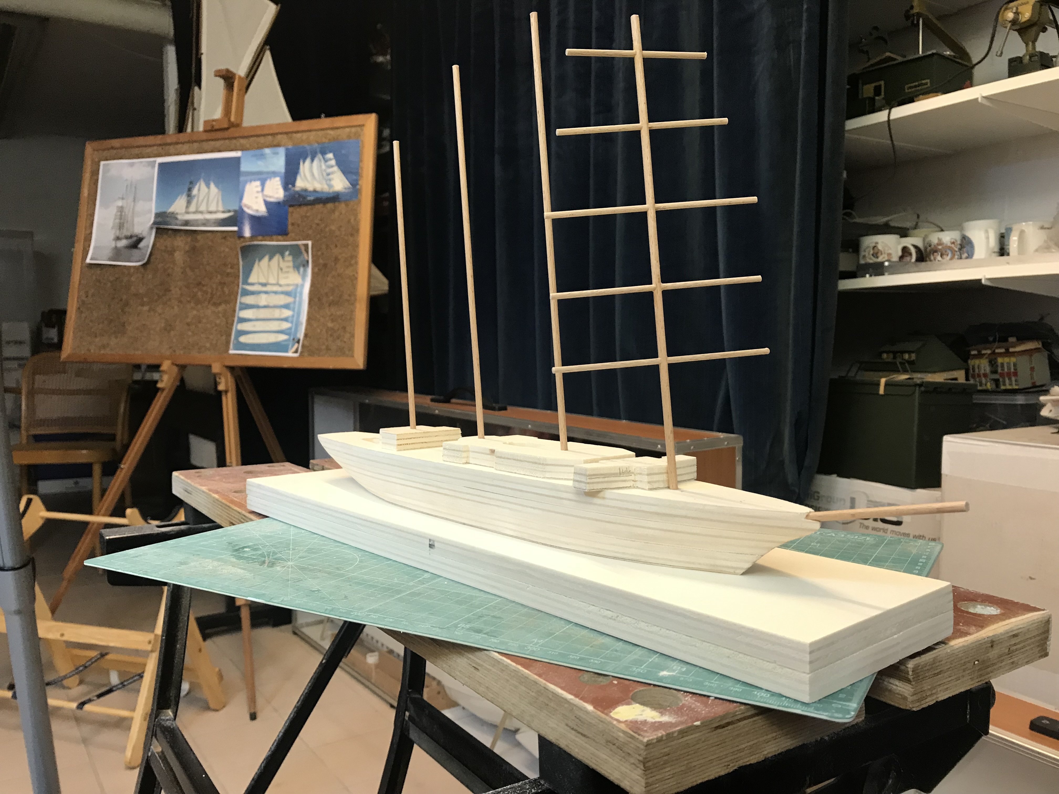
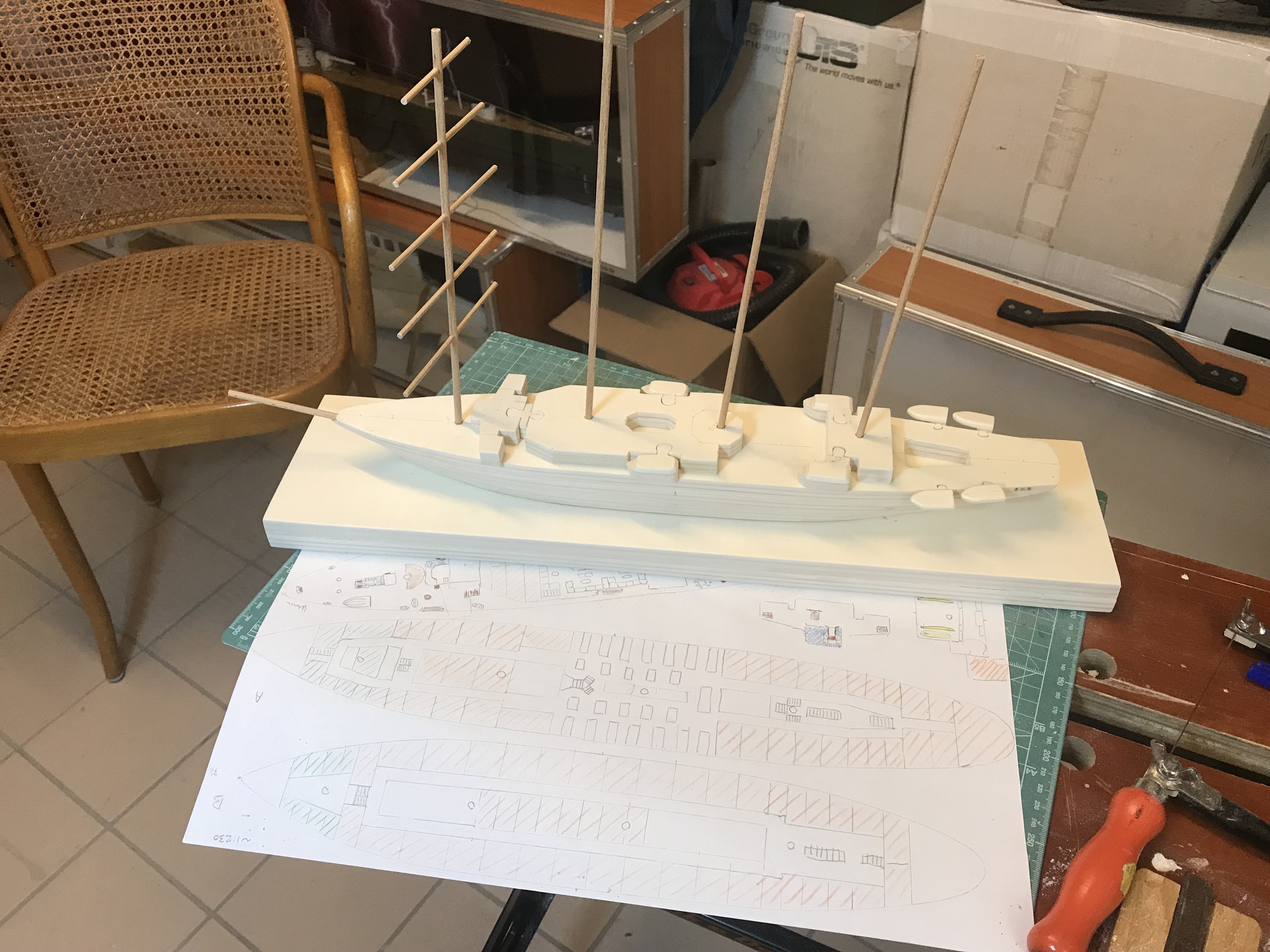
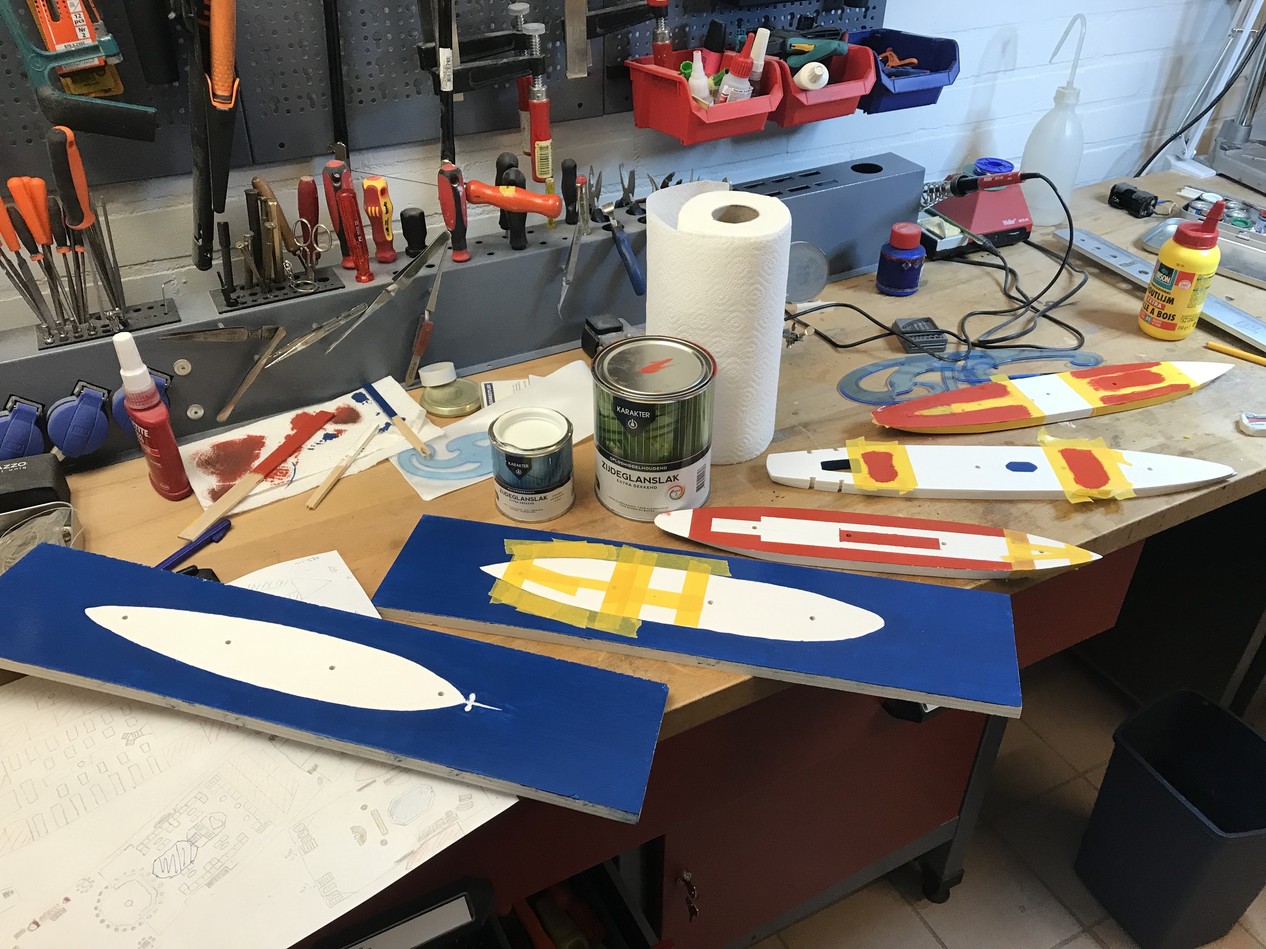
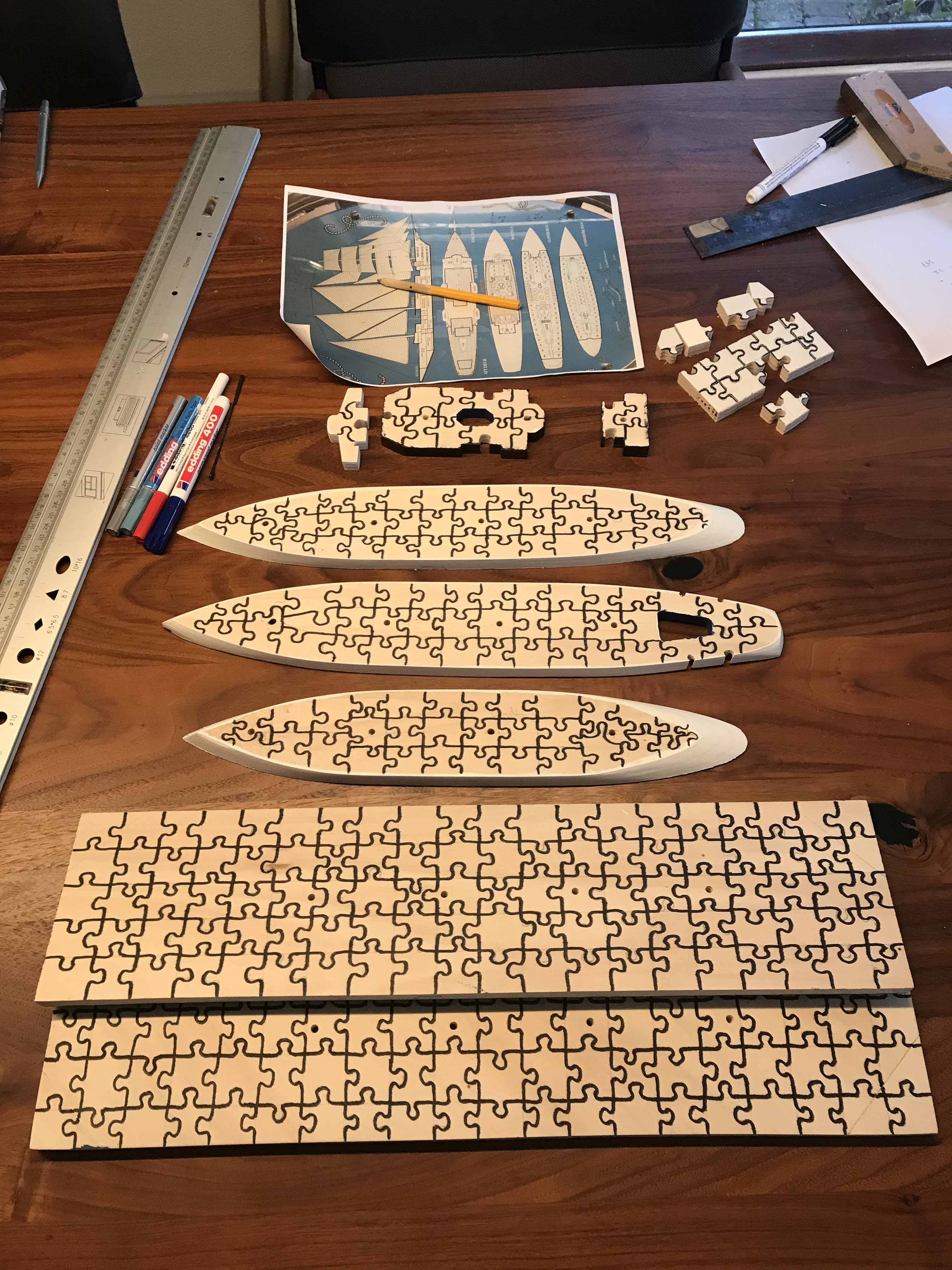
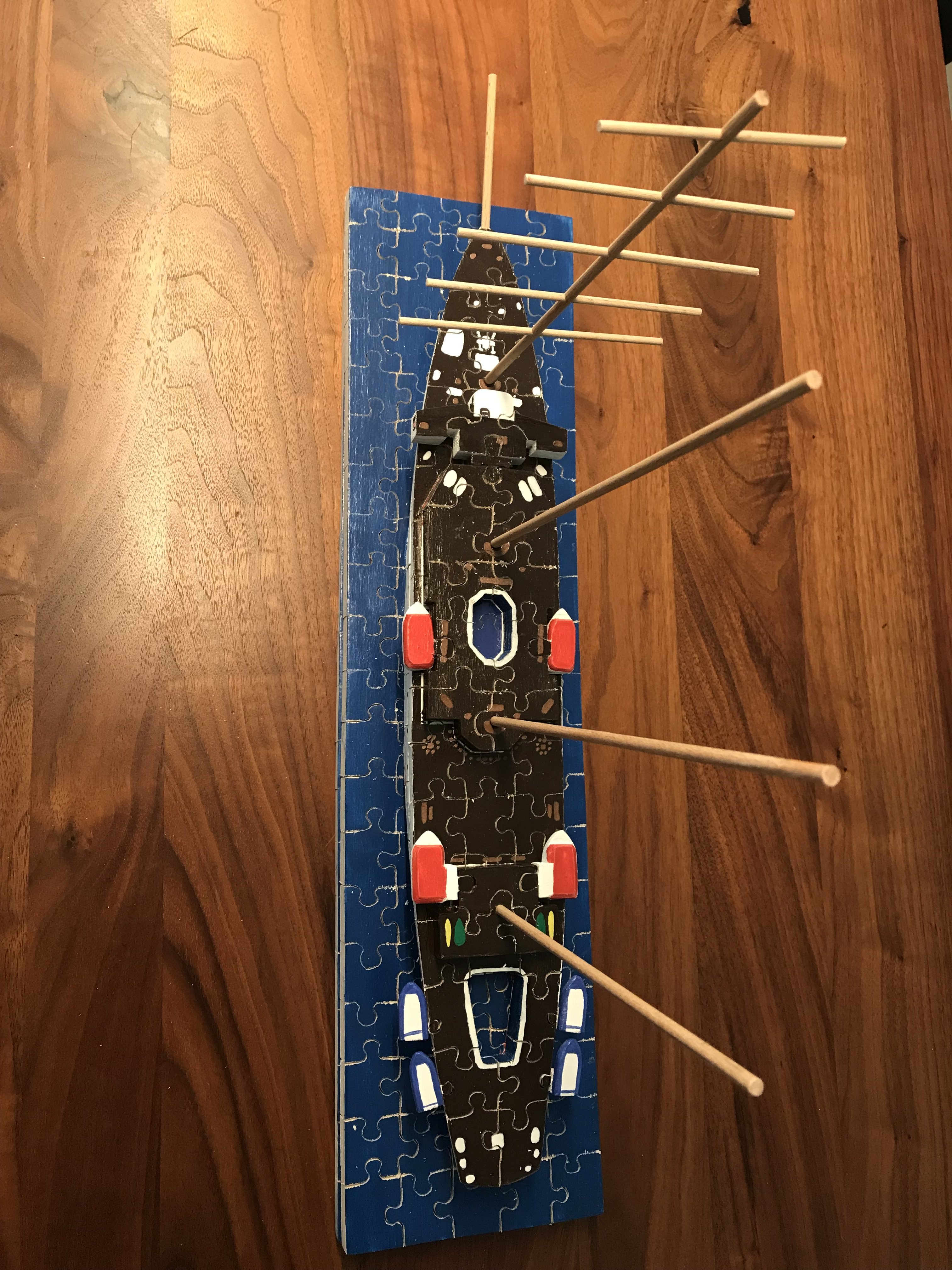
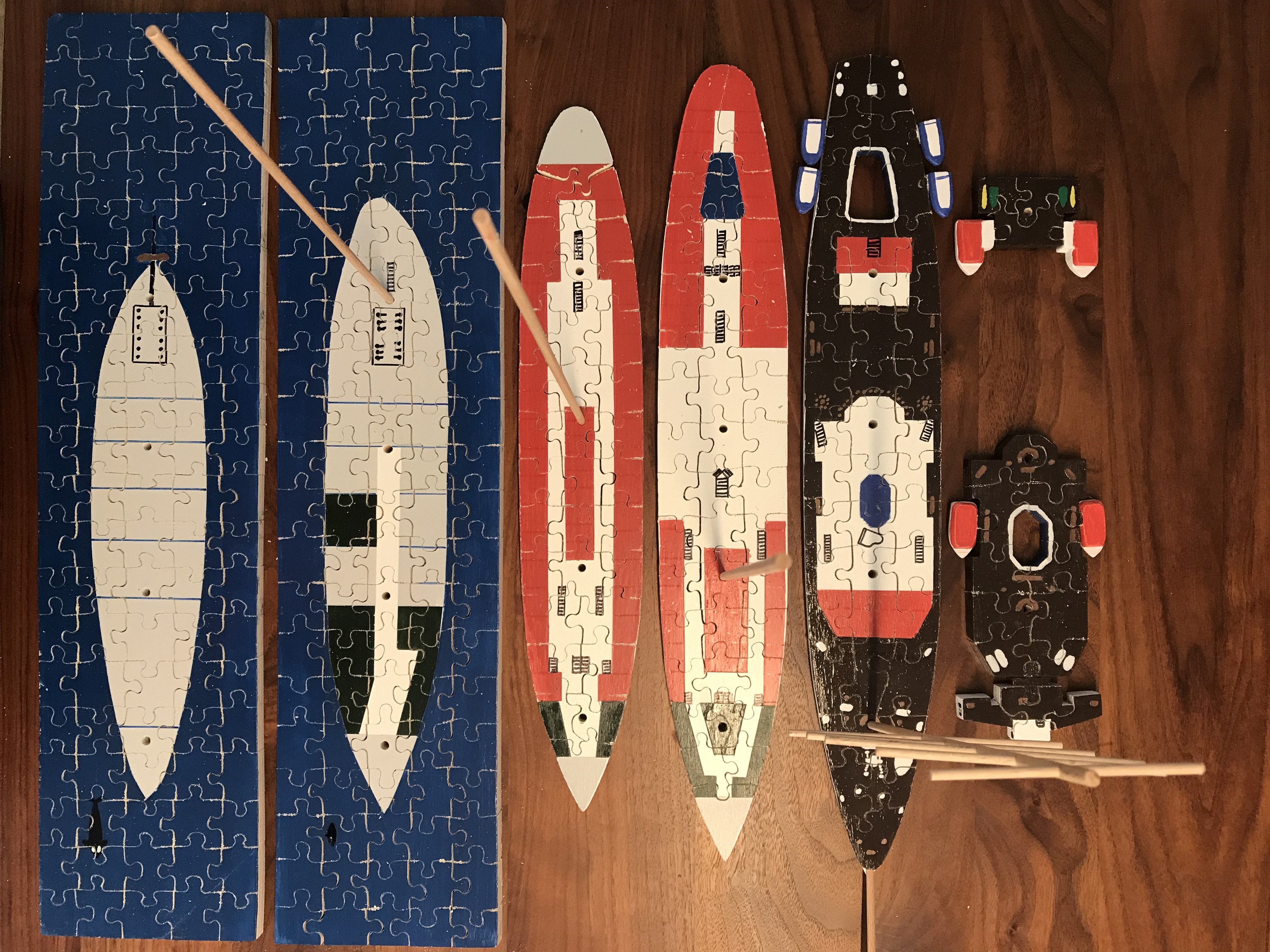
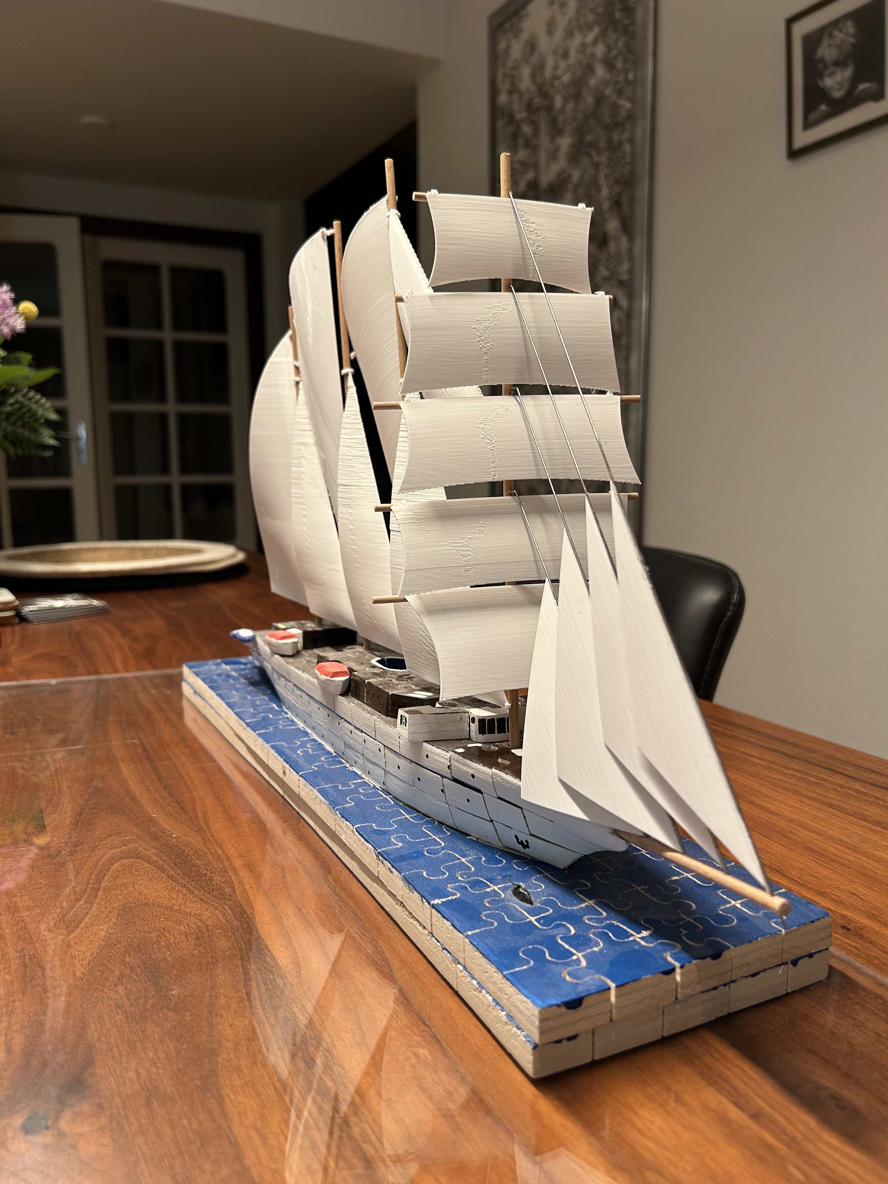
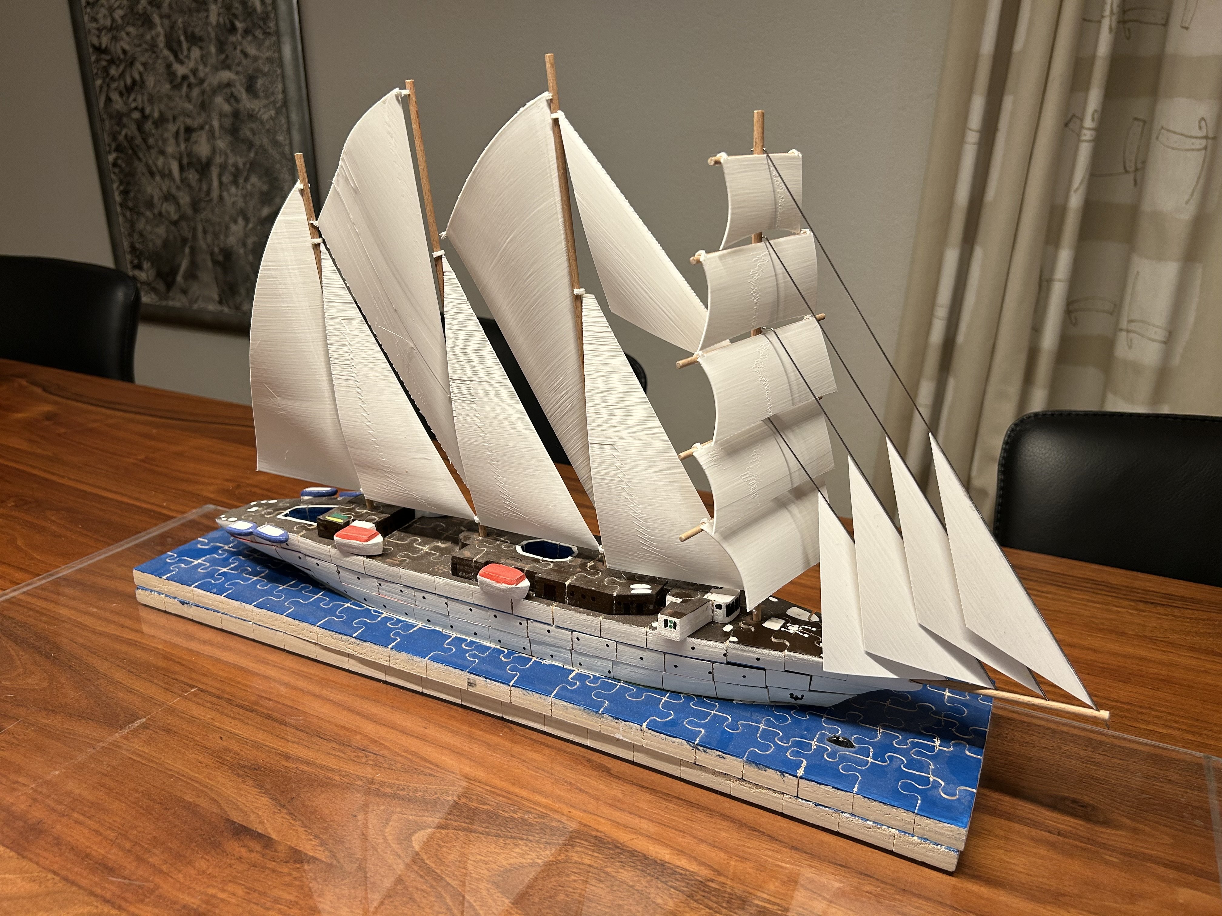
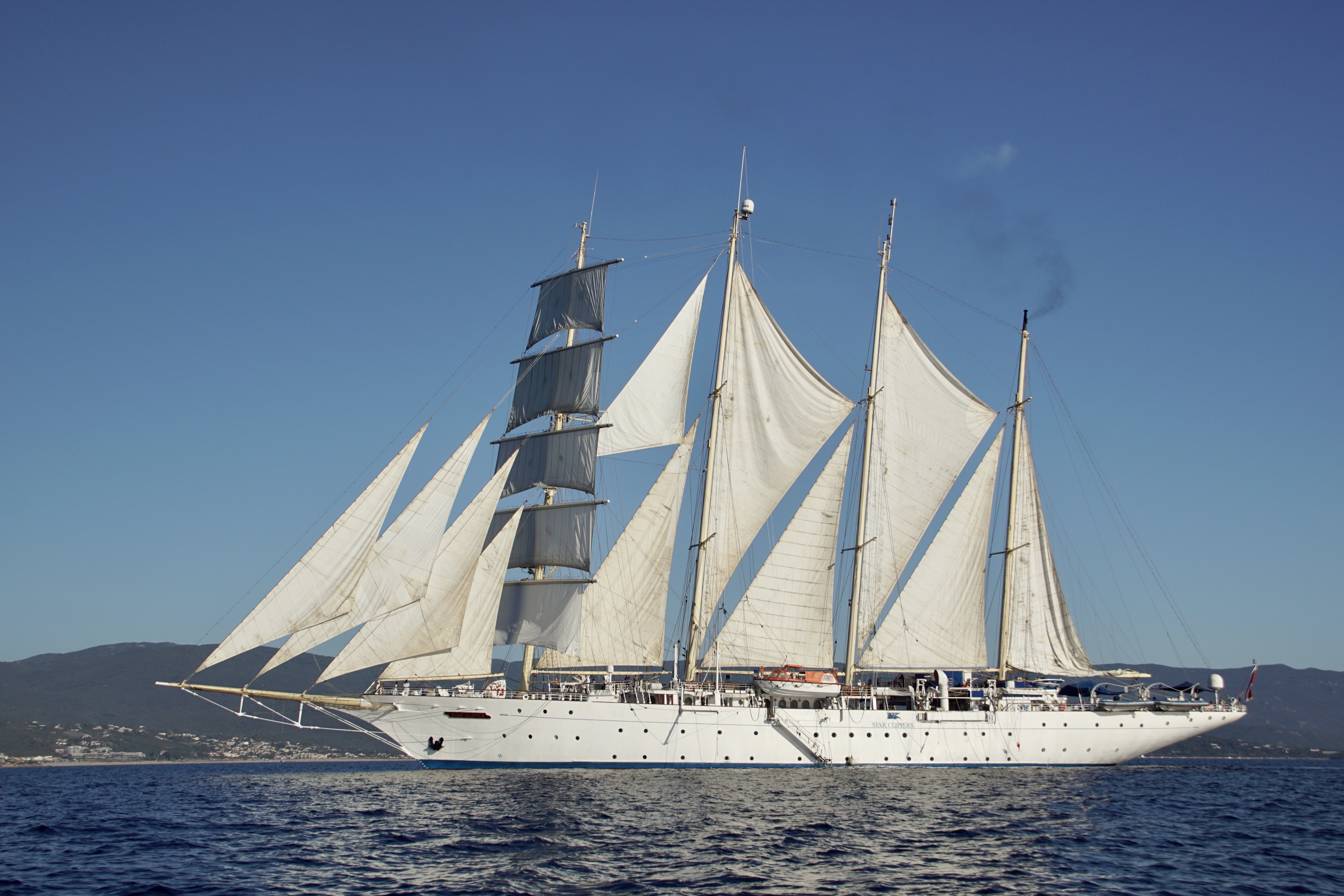
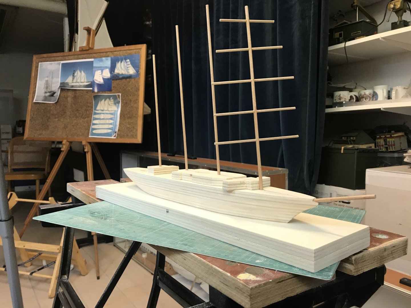
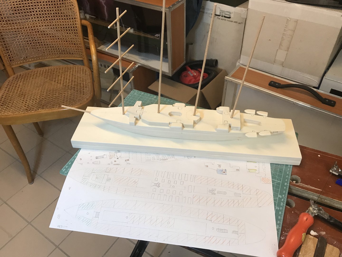
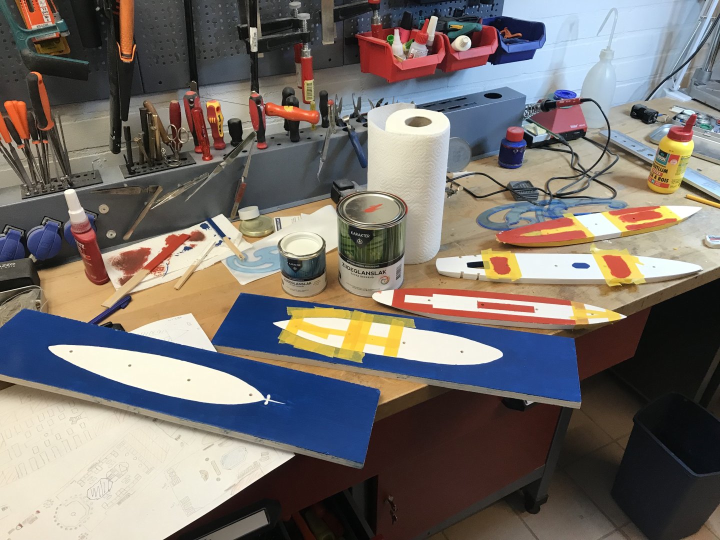
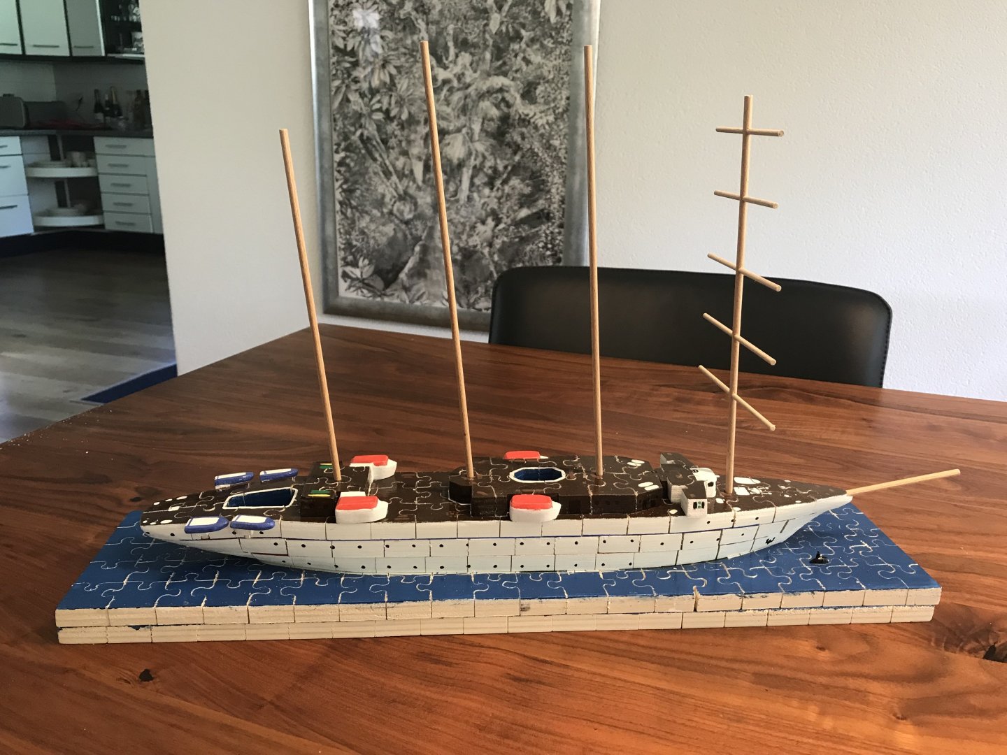
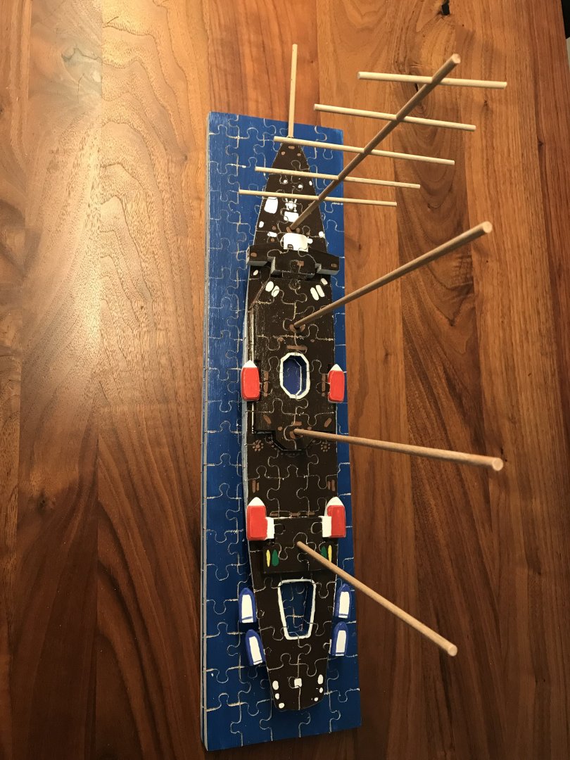
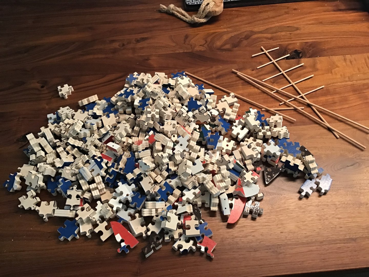
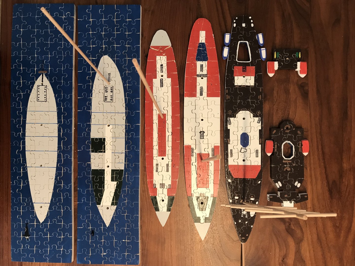
I think I had this idea after an episode of “The repair shop”, a UK TV program. Someone brought in a model of a ship, cut into puzzle pieces. Having done a trip on one of the nicer sailing cruise ships, I thought it would be nice to have a puzzle of the ship. “Star Clipper” is a 115m 4-master sailing ship (with engine, note smoke coming from the mizzen mast) from 1992. It can carry up to 170 passengers and has the first mast square-rigged and the others “Latin” (is that barquantine?). It’s a wonderful holiday opportunity, sailing in the Mediterranean or Caribbean depending on the season. The basic idea was to construct a “bread without butter” model of the ship, with each board representing a deck of the ship. Each board/deck would have its actual layout painted on it, and then the boards were cut up into puzzle pieces. I happened to have in my vacation photos a picture of the safety poster showing deck layouts (and sail layout). I did not have any plans and thus I’m warning the community that this is fun-quality rather than museum-quality! Here the first three boards (and the deck layouts prints of my photos below the). These represent the ship above the waterline. They will sit on two additional boards that contain the sea and the below waterline hull. The 5 layers will be held together by the 4 masts only, for which holes have been drilled under the appropriate angle. The hull was shaped by hand with the boards in a vice using a plane and sandpaper. next, the deckhouses, tenders and masts were added. I made a simplified deck planes, with color coded spaces (white-common spaces, red-passenger cabins, green-crew spaces) now turned all boards over and drew the puzzle pieces. A couple of days on my dremel jigsaw and numerous saw blades later I had around 300 puzzle pieces, still neatly arranged by deck. off the starboard bow is even an orca in the sea. Assembled: and then came the main test: it took about three hours to revert from the puzzle pieces to the model again. The normal strategy of finding the corners and edges first does not work, as there are so many of them….the motorised jigsaw was critical, as each puzzle piece must be cut perfectly vertical or the puzzle won’t fit. finally (and a few years) I added 16 more pieces in the form of 3D printed sails. She looks great and the puzzle has been completed several times! thanks for reading!


-
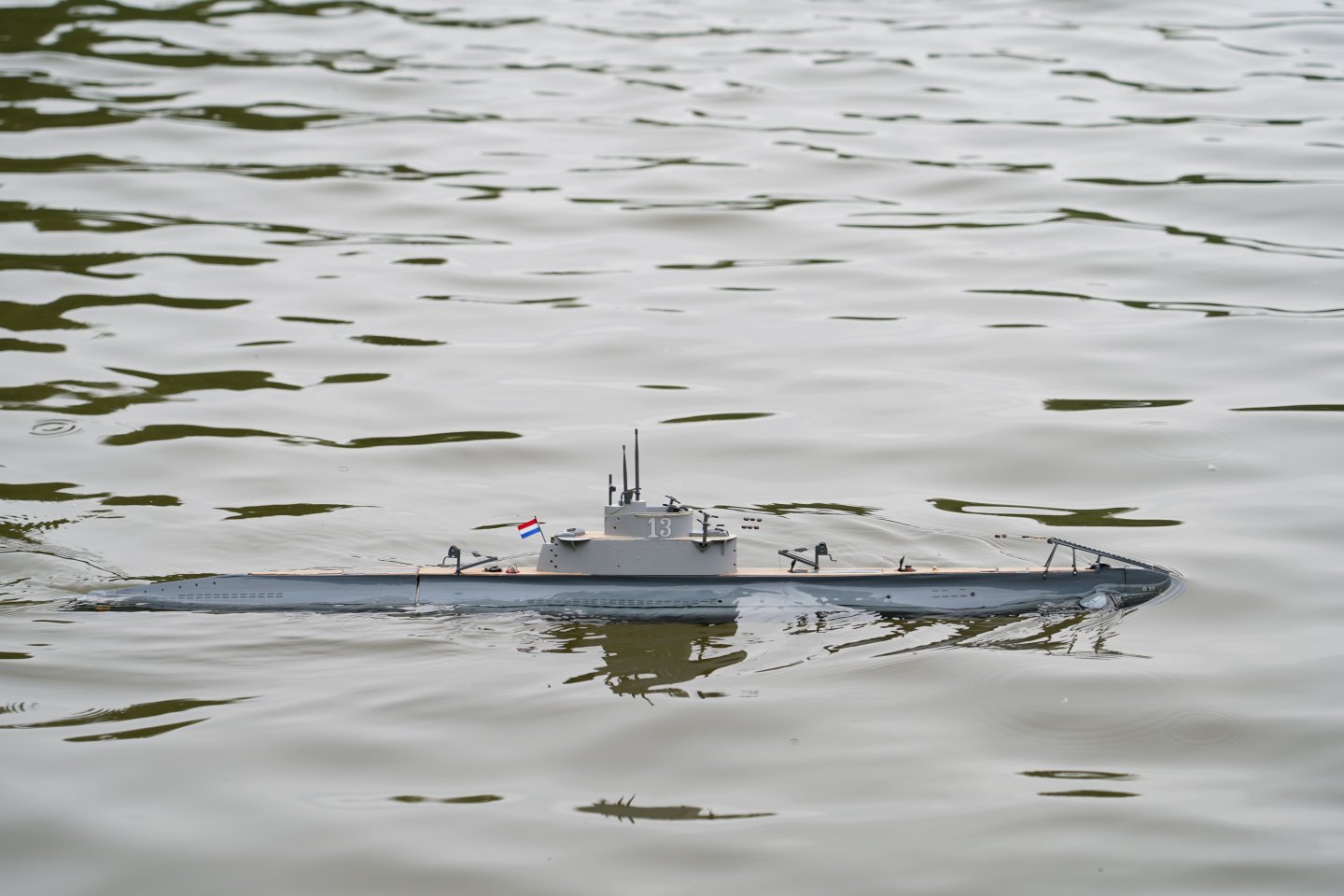
yesterday at my model boat club O-13 made her maiden test. Water was perfectly clear and just still liquid. The evening hours made it a great test for the LEDs (but somewhat scary for everything else). Made two small rounds, one on the surface and one semi submerged - the ballast is “on the safe side” and she does not want to dive at low speed yet. Filming was a challenge too but a friend at the club recorded the event. https://youtu.be/nnN6TKy9Hg0?si=mhxLVOyGmUrWRlAB
-
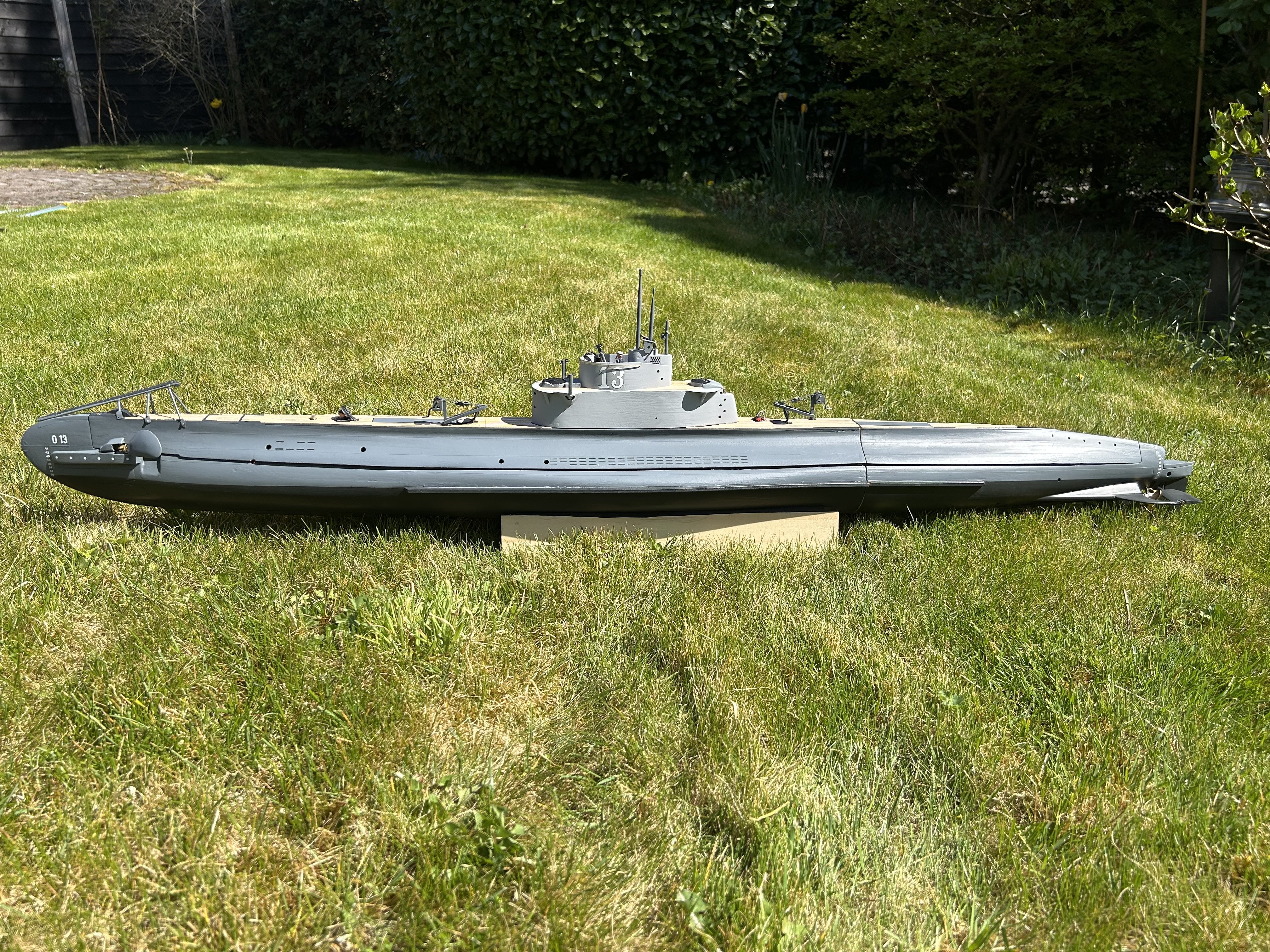
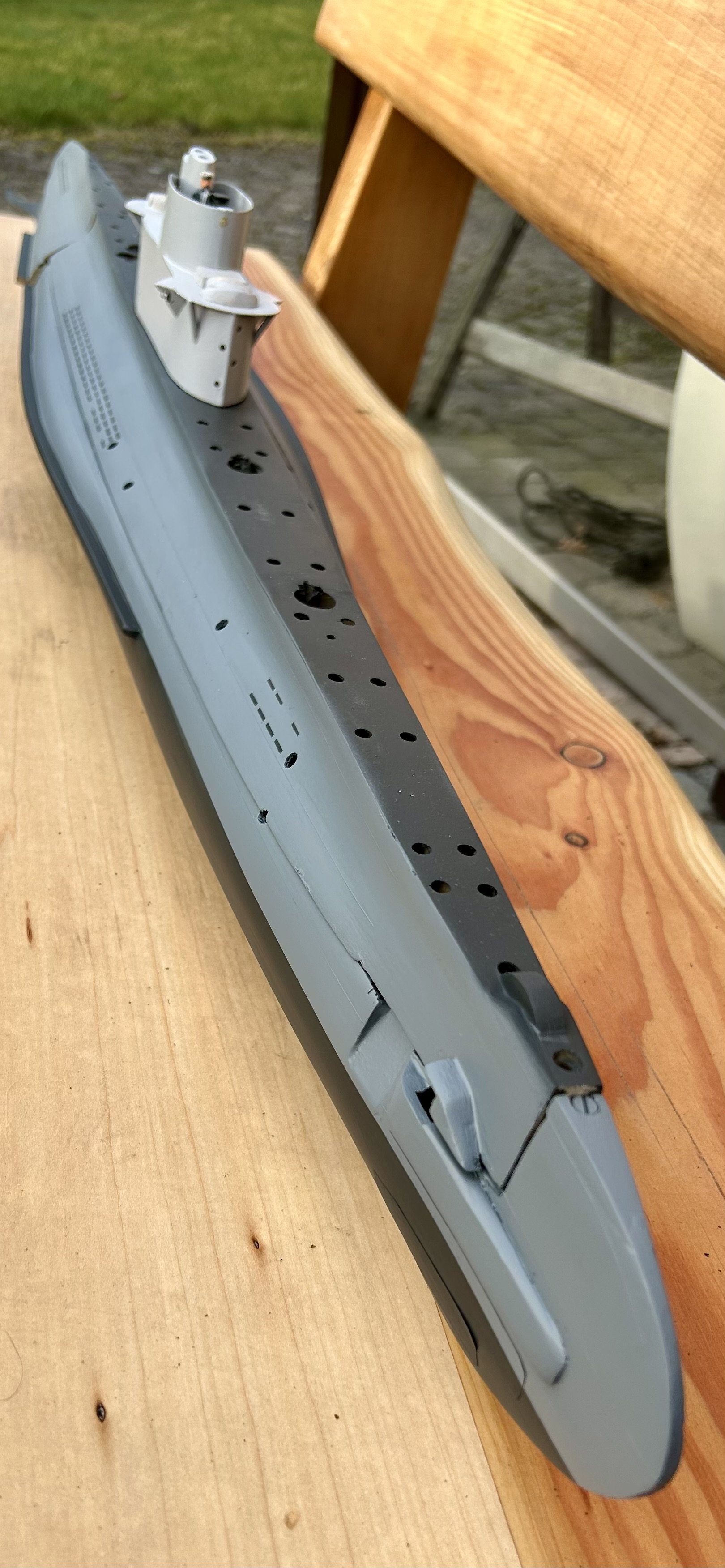
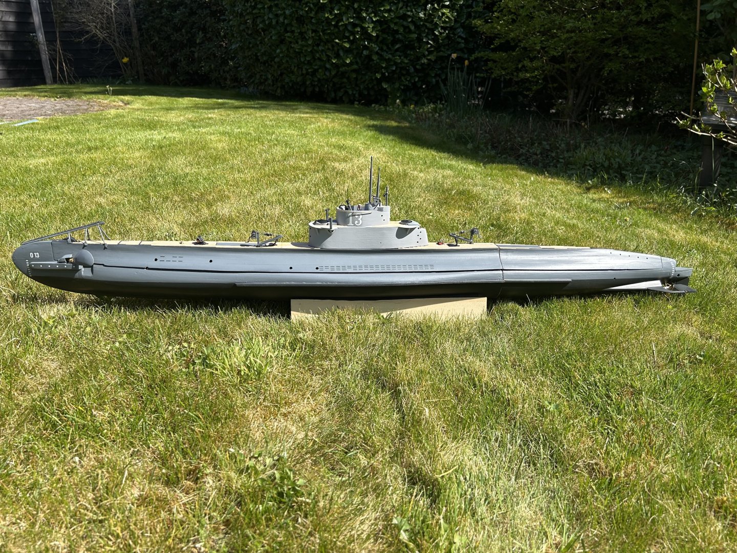
Recent focus has been on testing the boat. Based on the last bath test, I glued about 40 grams lead in the bow, and fixed with a small bolt 3 plates of 5 gram lead each inside the water tight compartment all the way in the bow. This for future trimming (as still a lot of small details need to be built and mounted). The stern was already heavy enough. Now, most photos of O-13 show her trimmed on the surface with bow high and the deck sloping down towards the stern. To achieve that and still keep the boat horizontal when dived, I glued a 30ml piece of building insulation foam in the stern, but above the waterline. I then placed 30 grams of lead under the foam and beneath the waterline. This cancels each other out when submerged, but pulls the stern down when on the surface. In the bath it looks “good enough” for now. In the bath the pump took 25 seconds to fill the tank and submerge the boat. That’s about the same as a WW2 sub could achieve. The pump actually works faster than its spec! The water sensor on the arduino now switches the pump off just when the mast, through which the air from the tank is pumped overboard, becomes filled with water. So it seems the tank fills completely (hopefully leaving no air bubble that can move fore and aft). The arduino also correctly measures the battery voltage and alarms when too low. The fore planes deploy but there is too much play in them. The crew goes below just before the dive but “forget” to close the hatches behind them. Oops. When the tank is full, the boat is trimmed to “decks awash” the props and diveplanes can then submerge the boat under very low speed. But that is for the next test. so the work on the technology is nearing completion, but much work remains. These pre-WW2 subs had a wooden deck, I want to build the “net cutters” on the bow, handrails, periscopes, radio antennas and bridge equipment, and of course get to painting. O-13 was deployed in 1937 during the Spanish Civil War to escort ships into the Mediterranean, and had clearly visible Dutch flags painted on the conning tower. That’s what I’m aiming for. its almost a year to the day since I started this build , I’m sure 2025 will see a lot more work on O-13 but also some nice sailings.


-
Happy holidays everyone! Captain below working as intended! https://youtube.com/shorts/58Pdq6fnKrM?feature=shared
-
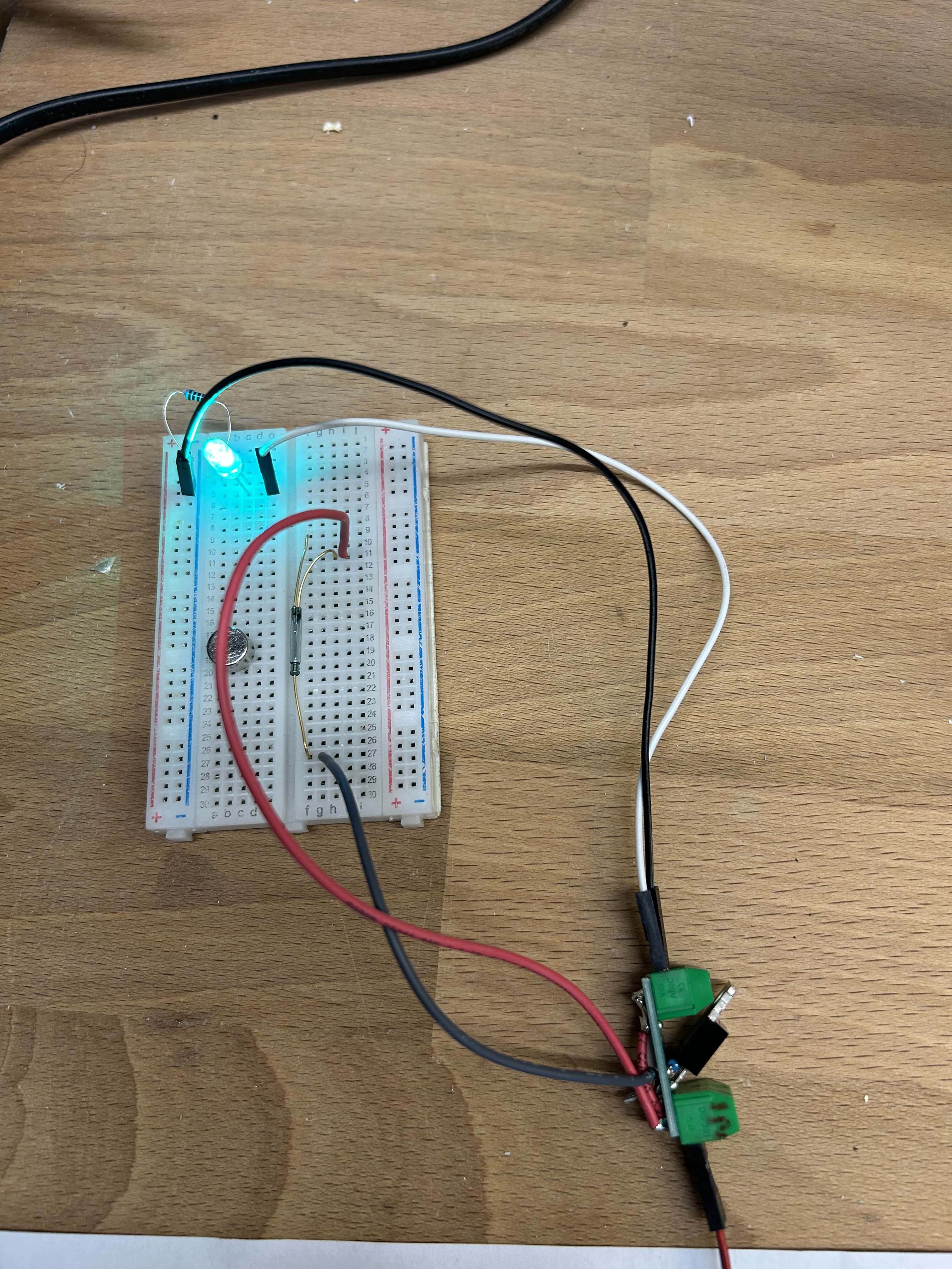
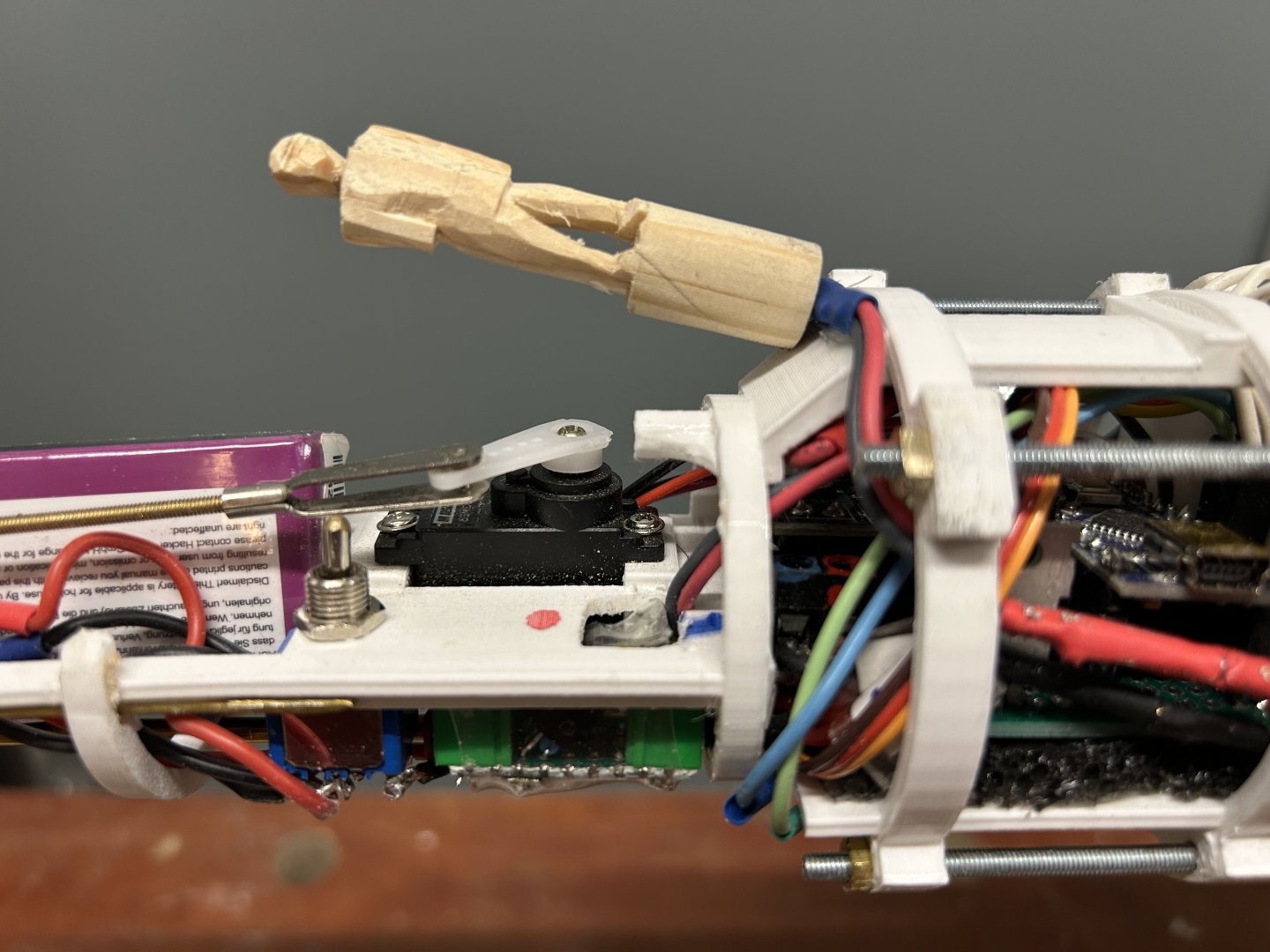
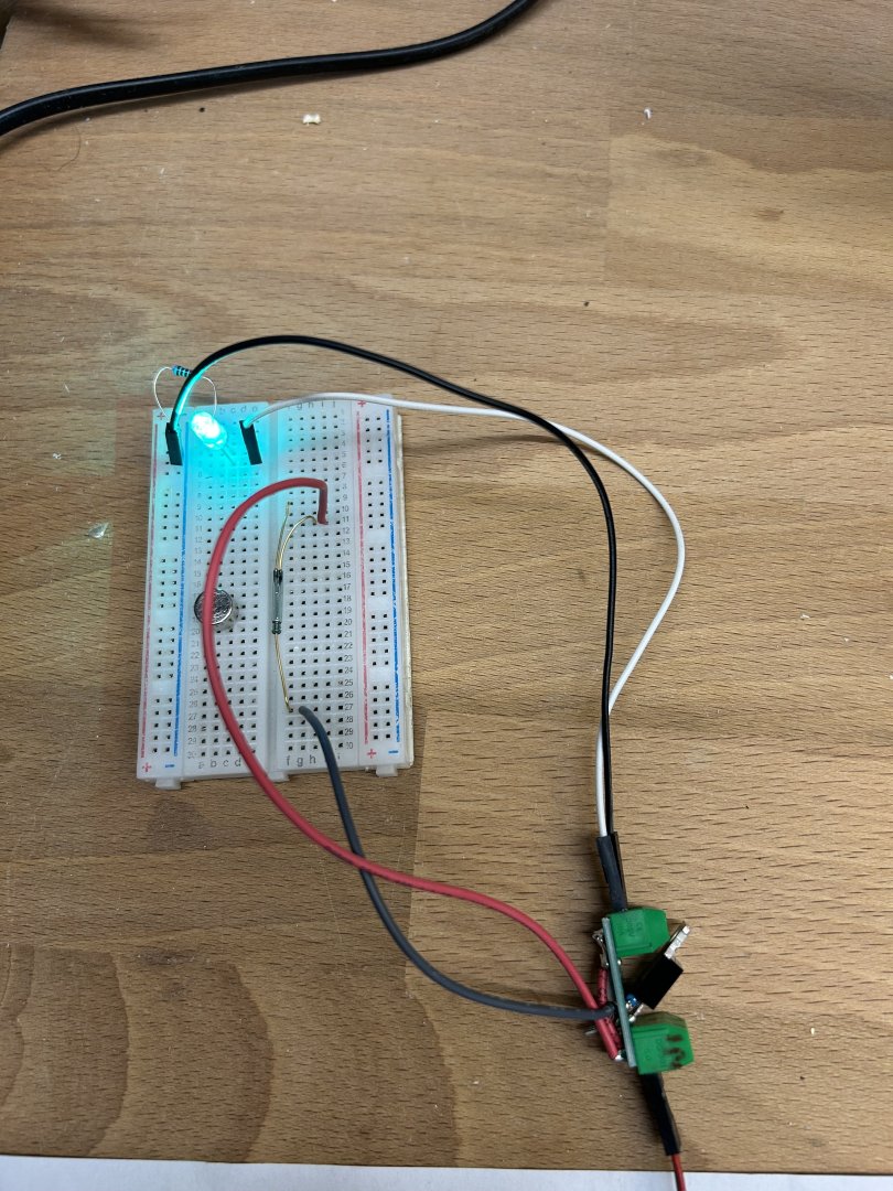
As usual, the first wetting of the boat has revealed some work. First, I glued 500 grams of lead in the bottom of the ship, below the WTC. Also the techrack has too much friction, so I straightened out the M3 wires and adjusted the nuts. Sanded all contact points with the PVC tubes. It now runs better. Also, I wanted a magnetic switch so the whole boat can be switched on and off without opening the bajonet, using a magnet. The normal units use relais, and I did not have the space for them. Instead I made a small circuit with one MOSFET, one resistor and a reed–switch. I’ve tested it switching up to 2.2A, and when the reed is open there is no measurable current use. Seems to work! The reedswitch is located inside the water tight compartment, underneath a hatch. I put a magnet inside a wooden crew member, and when I place this in the hatch, the boat is switched off. On removal before sailing, the boat is switched on. It just fits between the existing main switch inside the WTC and the Arduino controller. I think the techrack is now complete, and next step is to test the boat in the bath, further balancing, filling and emptying the temp to dive and raise the boat and unfolding of the planes.

- 97 replies
-
- 10
-
-