MORE HANDBOOKS ARE ON THEIR WAY! We will let you know when they get here.
×

FreekS
-
Posts
216 -
Joined
-
Last visited
Content Type
Profiles
Forums
Gallery
Events
Everything posted by FreekS
-
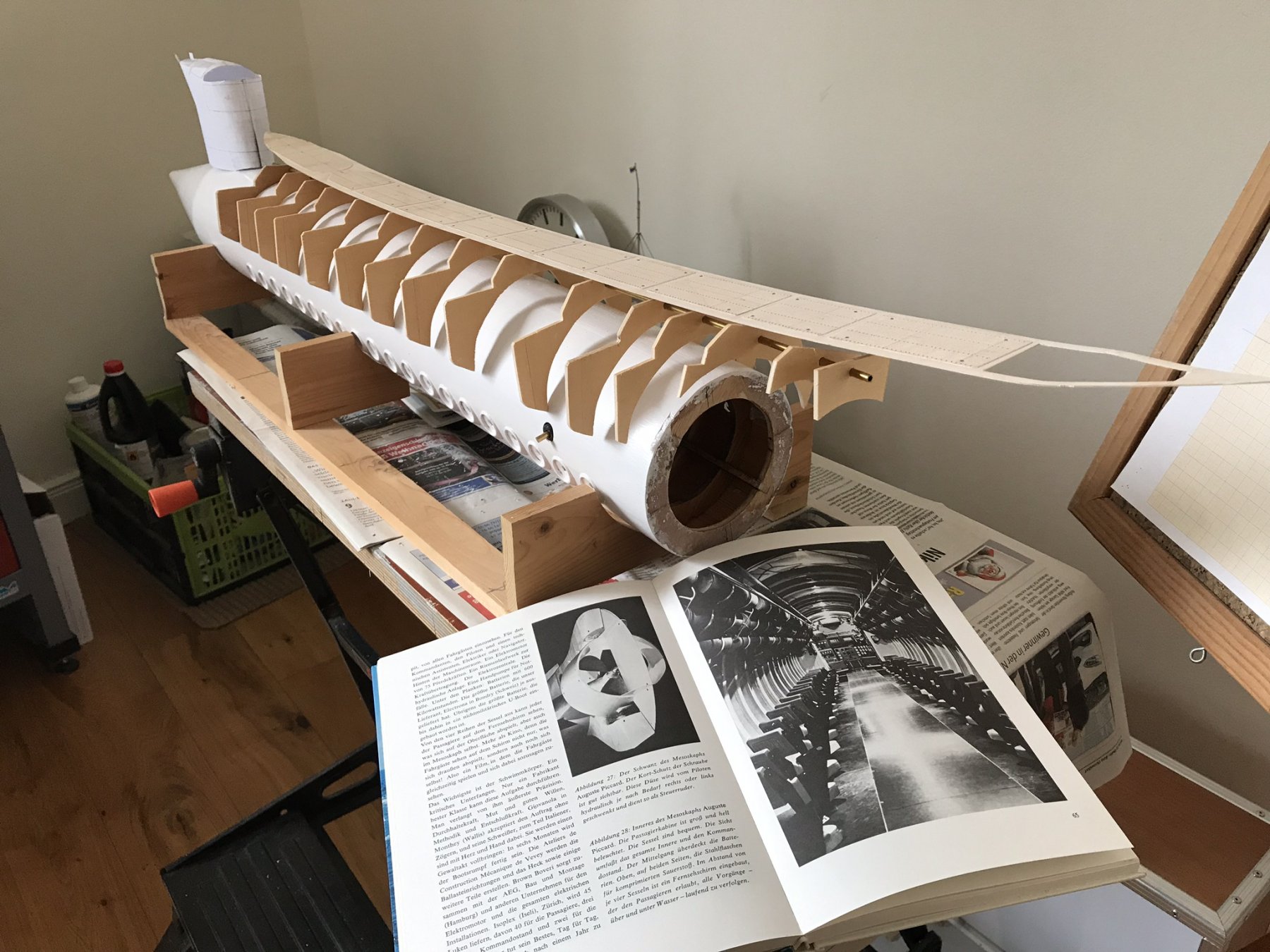
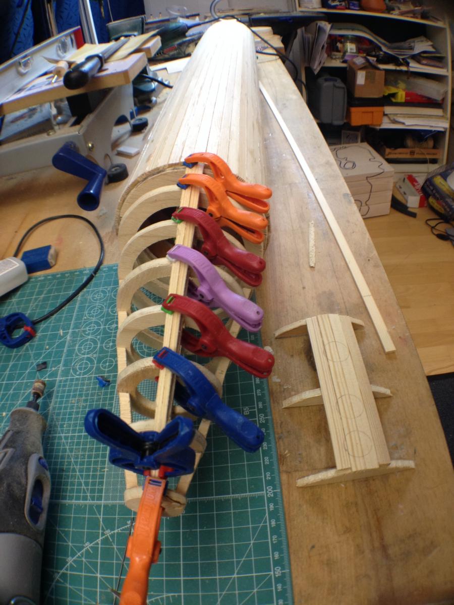
Well, I’m building again! My other projects are finished and as there is little model ship sailing going on I don’t need much time for repairs! Been working on the deck section of the Mesocaph, which will fit on top of the cylindrical pressure hull.
- 55 replies
-
- 6
-

-
- auguste piccard
- submarine
- (and 2 more)
-
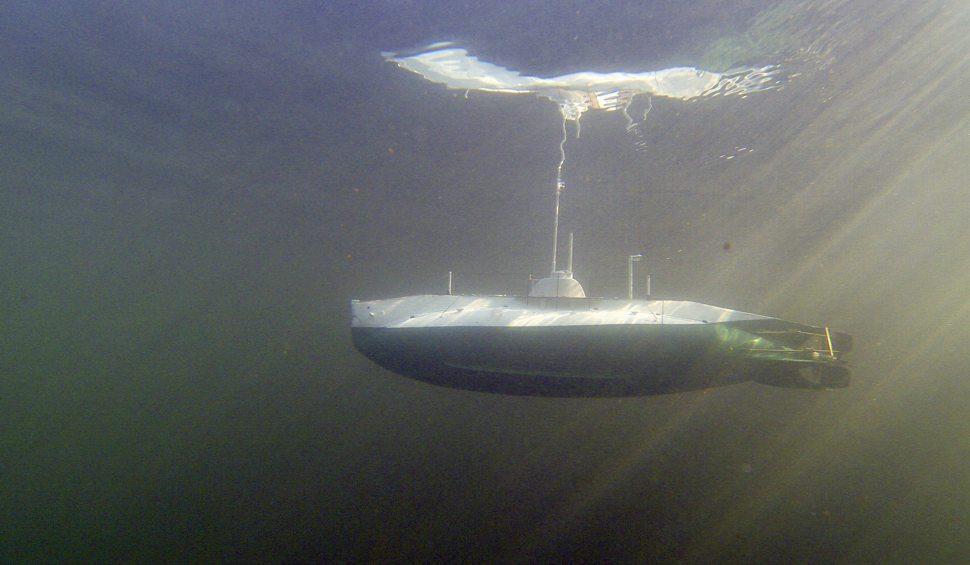
Hi Mark, here’s the latest generation of the torpedo - in “my neighbors” pond This second video is from 2015 and shows the boat firing torpedos. Note, these were not electric - but rubber-motor powered. freek
- 55 replies
-
- 6
-
-
- auguste piccard
- submarine
- (and 2 more)
-
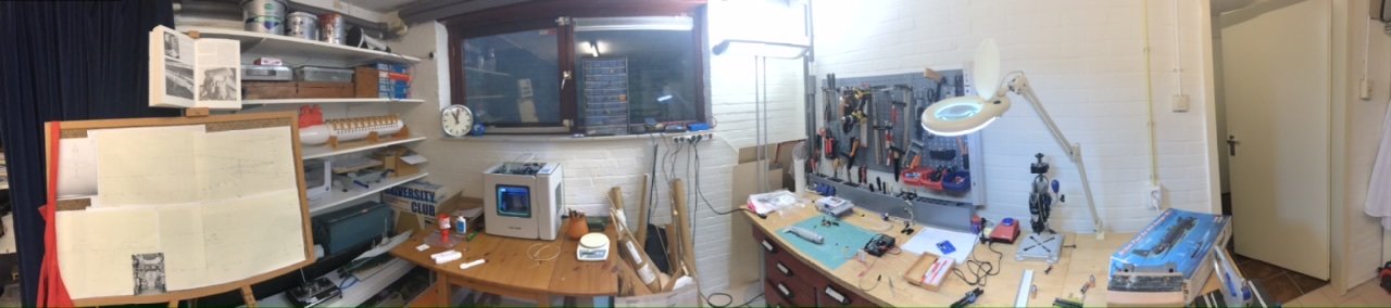
Here my “Dutch” shipyard. piccard is in the far corner, toros and avenger on the workbench
- 55 replies
-
- 3
-
-
- auguste piccard
- submarine
- (and 2 more)
-
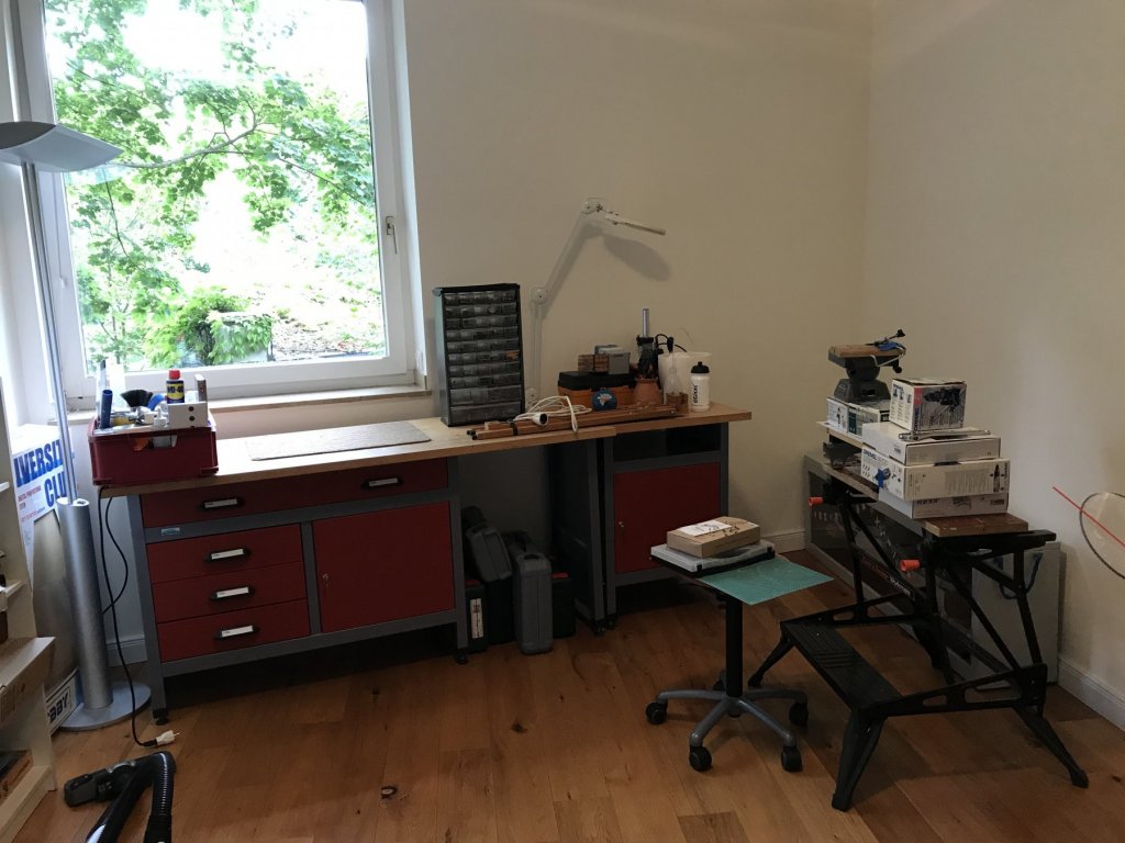
Hi Piet, sorry my project is going so slowly and I missed your post! I’ve got two parallel projects happening, one was to build 1:50 electric torpedos (weight 7 gram) for my K-XVIII. I succeeded thanks to the trend to “supercap”, using a 1F (correct, not picoFarad) capacitor gives me 10 seconds and 5 meter range. The toros work, now I need to update the firing mechanism of the two deck tubes on K-XVIII. The other project is to take a 1:48 plastic modelkit of an ASW Grumman Avenger, and make it into a working sub - flying loopings and barrel rolls under water. That one is still in the “tough” phase. Yes the move to Holland happened in July - I “retired” (the word still sounds weird) and moved back to my house in Baarn, between Hilversum and Amersfoort, that we left 10 years ago. Needed a serious update of insulation and solar panels but it’s all done now. My new workshop is also an improvement! Thanks Freek
- 55 replies
-
- 1
-
-
- auguste piccard
- submarine
- (and 2 more)
-
Hi all, Progress continues very slowly, and with a major interruption, as my wife Kien and I are moving back from Germany to Netherlands early next week. That means EVERYTHING must be packed up, including my shipyard! So here it is, I waited until 5 days before the movers came, but I’ve not seen this room this tidy in years! The last work was on an inside frame for the sail of the boat. Underwater the sail will have quite some water resistance so Picard built the sail around a metal frame (see pic in post #20). I decided to make it out of 2.5x2.5 mm messing, soldered together. I’m very mediocre at soldering, and initially all went well, then as new joints came too close to already finished soldered joints I switched to epoxy glue - enabling me to use the plastic sail as a mold. Still the soldered joints are weak and one broke already on packing (75W electric Weller, S65 solderfluid - it’s probably skill related, not materials!). Anyhow, once moved I’ll fix that. The frame will be glued inside the sail, the frame and 3D printed sail will sandwich the clear windows. LOOOTTTTTS more to do.
- 55 replies
-
- 4
-
-
- auguste piccard
- submarine
- (and 2 more)
-
Hi Piet! Mostly I use two-component epoxy (the slow curing variant as its waterproof). In this case there will also be a metal (messing) frame on the inside of the sail (it’s partly visible one one of the photos of the sub in Luzern) and I can hopefully sandwich the “glass” at least partly between the sail and this frame. That may reduce visibility of the glued areas. I might also paint those white on the inside. Not planned in detail yet...! Thanks for the likes and thoughts! Freek
- 55 replies
-
- 2
-
-
- auguste piccard
- submarine
- (and 2 more)
-
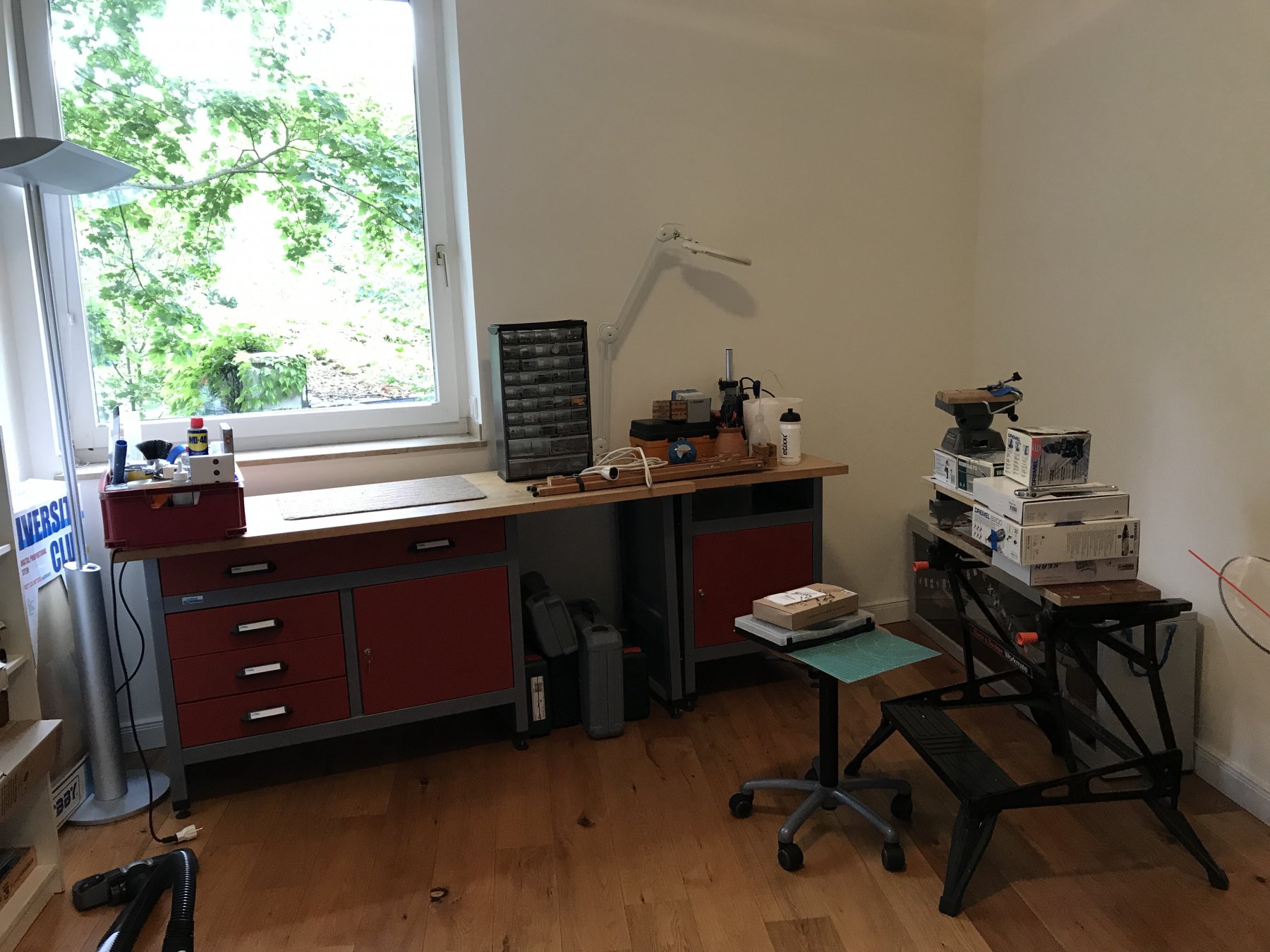
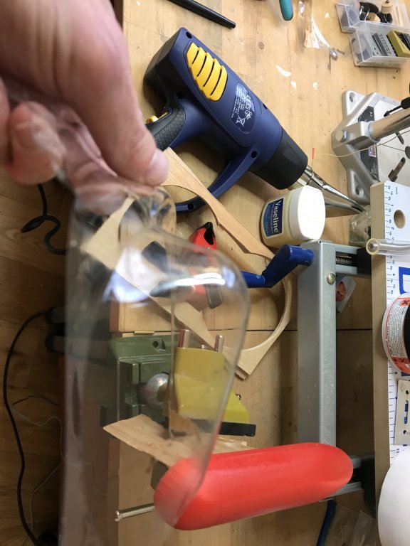
Hi all, today I tried to make one of the most curved windows of the subs sail. I used some transparent plastic (unknown origin) from a carton display box, a heat gun and a sanded 3D blank. Result of this test were encouraging, there is some yellowing of the plastic and the blank was not entirely the right shape, but it looks like a possible way of doing it!

- 55 replies
-
- 8
-
-
- auguste piccard
- submarine
- (and 2 more)
-
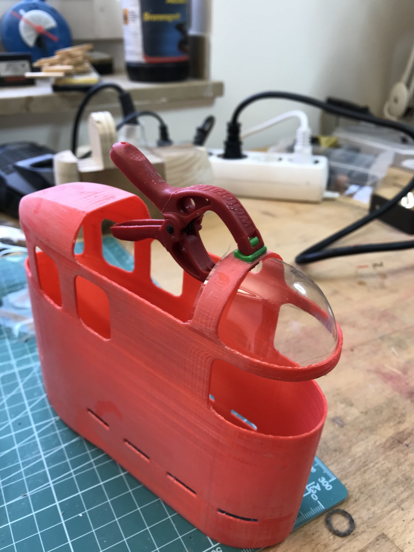
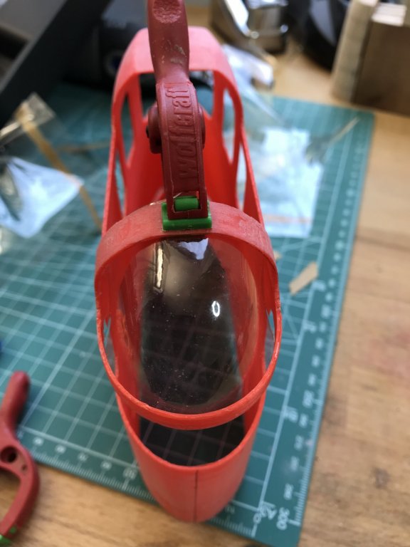
Amazingly, the printer finished the 16 hour printjob without a hiccup! I had spent maybe 3 afternoons behind my CAD program to design the shape of the sail, and expected to have to print it several times (I still may have to!). So after removing the support material I stiffened the sail with some foam to enable easier handling and sanding. Started with wet sanding with 60 and 120 waterproof sandpaper, and now may need to use some filler before continuing. I’m actually thrilled at the look of the sail! But it’s pretty fragile with couple of pieces having been broken and glued already. It’s slow going - sanding PLA is not so easy for me, but it’s going! Freek

- 55 replies
-
- 3
-
-
- auguste piccard
- submarine
- (and 2 more)
-
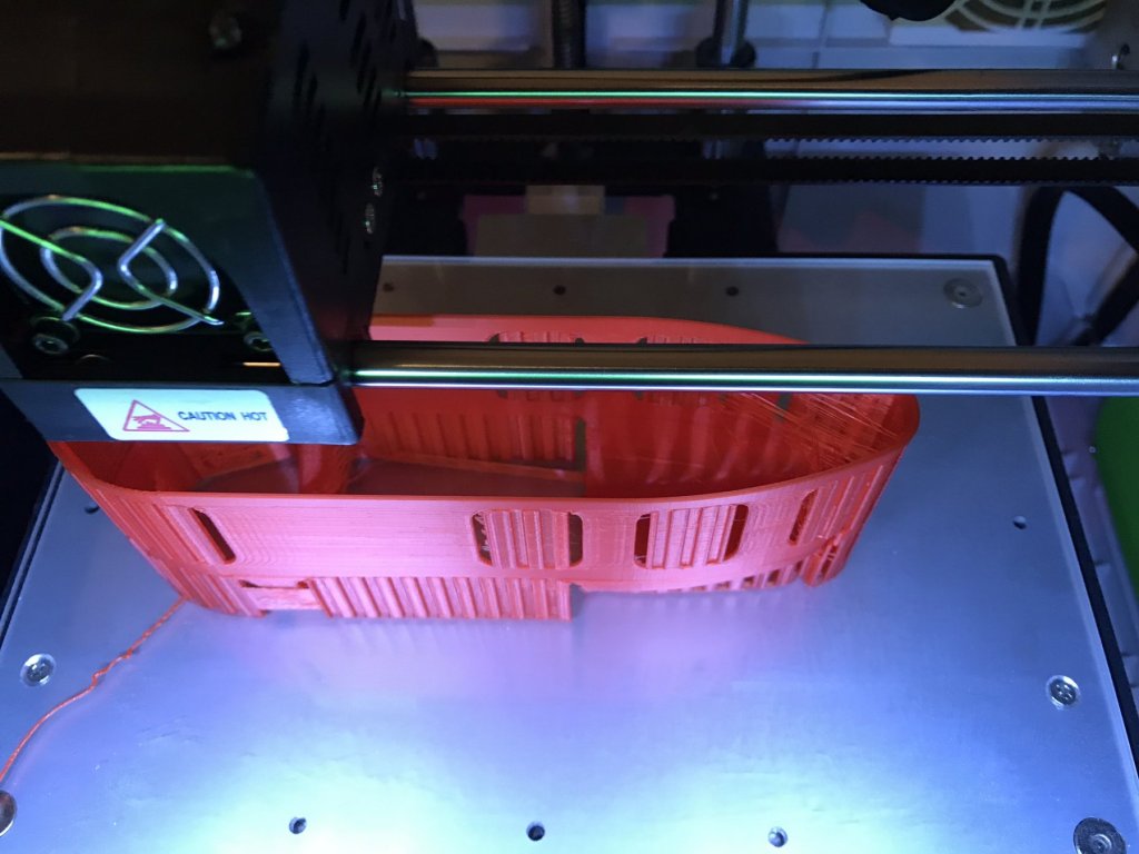
Now working on the sail (it’s upside down!). If the 3D print comes out - it was a steep learning curve in auto sketch fusion 360 - then the problem is reduced to making the heavily curved transparent windows.
- 55 replies
-
- 6
-
-
- auguste piccard
- submarine
- (and 2 more)
-
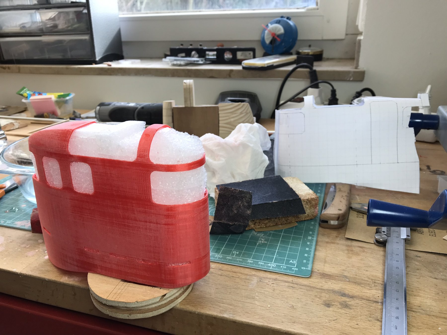
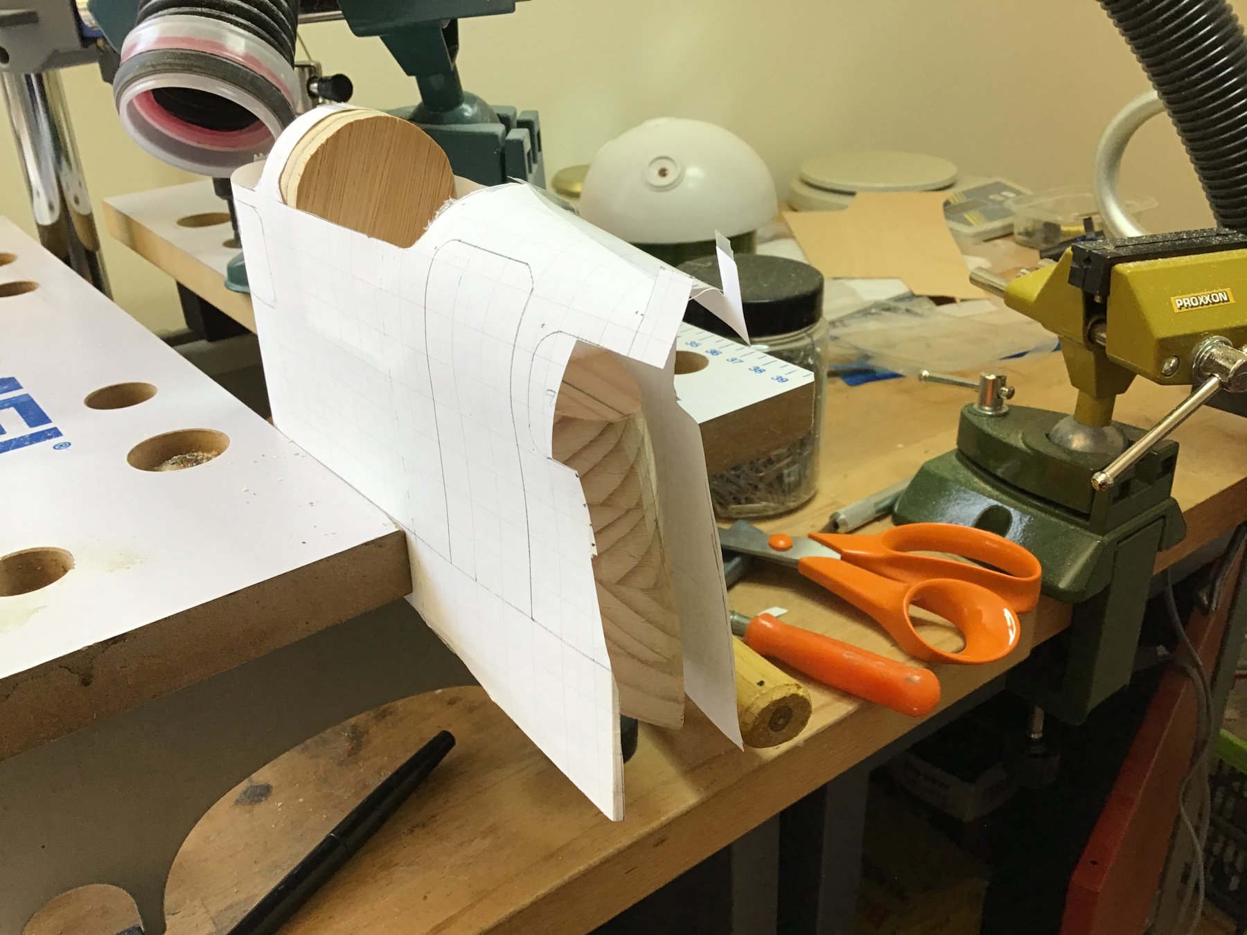
Hi all, I’ve been doing a bit more work on the Auguste Piccard as ....well....it still sounds weird but I retired! I did finish the 3D plotted portholes/windowsills. Have not cast the windows themselves yet. Then built the deck wil over a thousand holes in it, and now started on the “sail”. Here I can use some advice, it’s a thin metal sail with big windows and doors. Obviously it floods when the boat goes under. The shape is pretty complex (for an amateur like me) so I started building a wooden “blank” which I hope to use to shape 0.3mm messing around. Made a model out of paper (and a drawing on millimeter paper - do they still make that?!). But clearly the messing will warp in places and I don’t see how I can get that to work. Here are some photos - hope ya’ll have some pointers for me!


- 55 replies
-
- 9
-
-
- auguste piccard
- submarine
- (and 2 more)
-
Hi all! Another year gone by with very little building! I did manage to sail my two submarines a number of times this year, and with the repairs that inevitably come with that - and life in general in the way - Auguste Picard has taken a backburner. Yet i did do some work - the windowsills are printed, sanded and painted, the Hull is half painted, and the first work on the deck section has started. I do think I will have more time in 2019! Wishing you all a happy new year!
- 55 replies
-
- 6
-
-
- auguste piccard
- submarine
- (and 2 more)
-
Thanks for the Likes and good wishes! Oer the Xmas holidays I’ve printed all 43 „windowsills“, and started finishing the three that mount on the dome-shaped bow of the hull. Takes some sanding and a few coats of primer-finisher but looks OK. From some copper tube I sawed the thin rings, which were filled with clear 30 minute epoxy. These will be mounted in the 6mm holes after the bow assembly recovers its white final color. Then I will cast the conical windows in place. next is to finish the 40 windowsills that mount on the sides of the cylindrical hull. Ones done so far. freek

- 55 replies
-
- 7
-
-
- auguste piccard
- submarine
- (and 2 more)
-
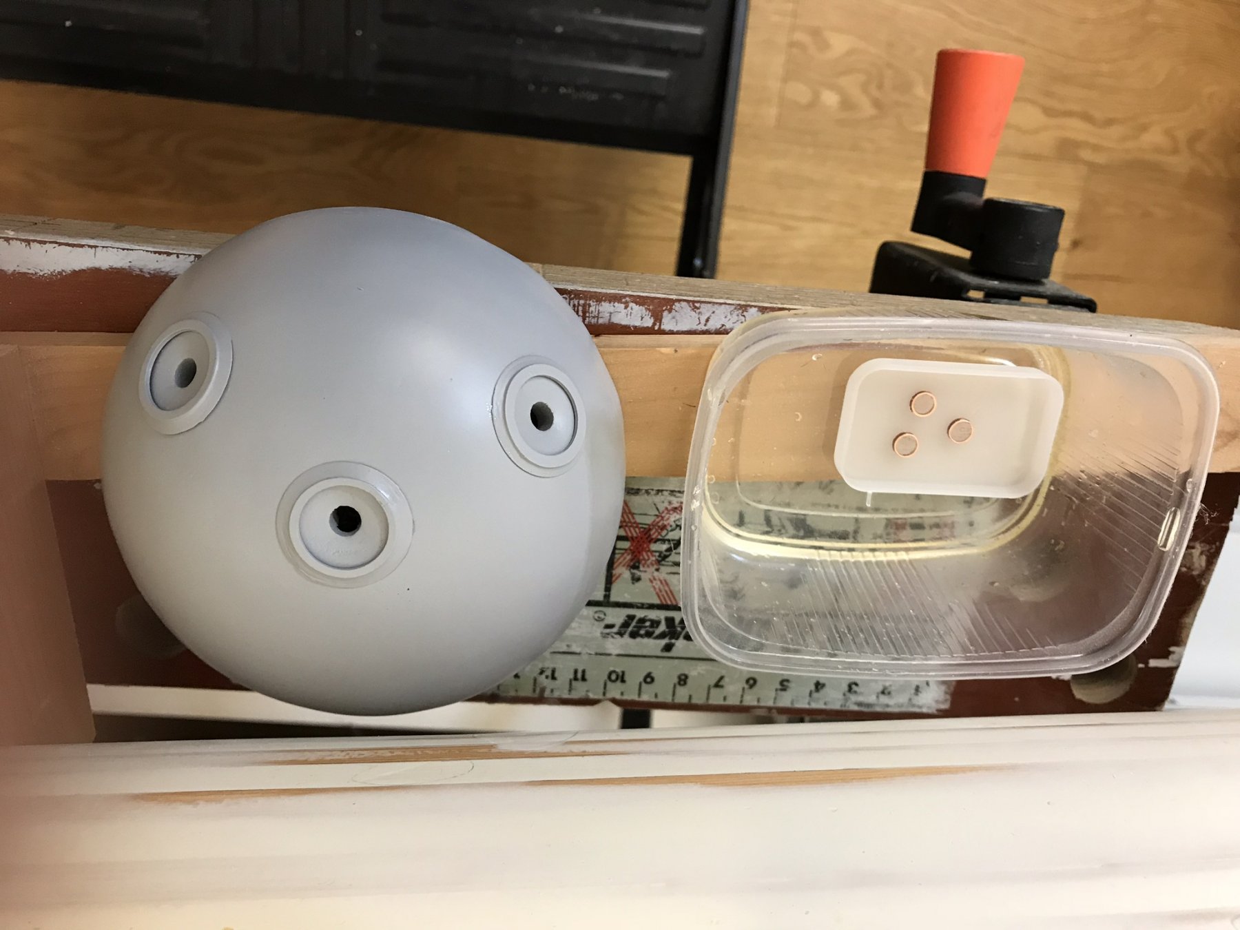
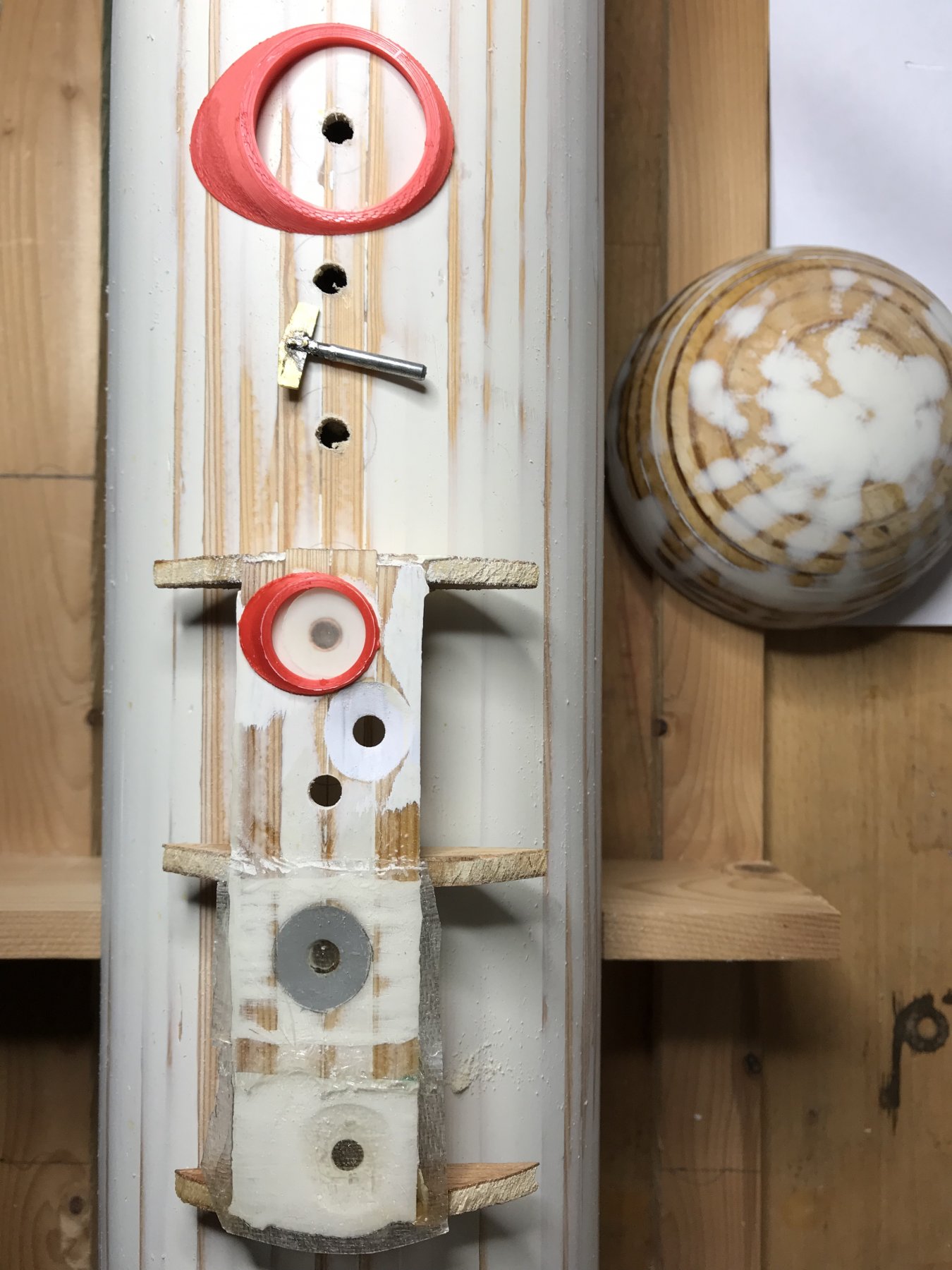
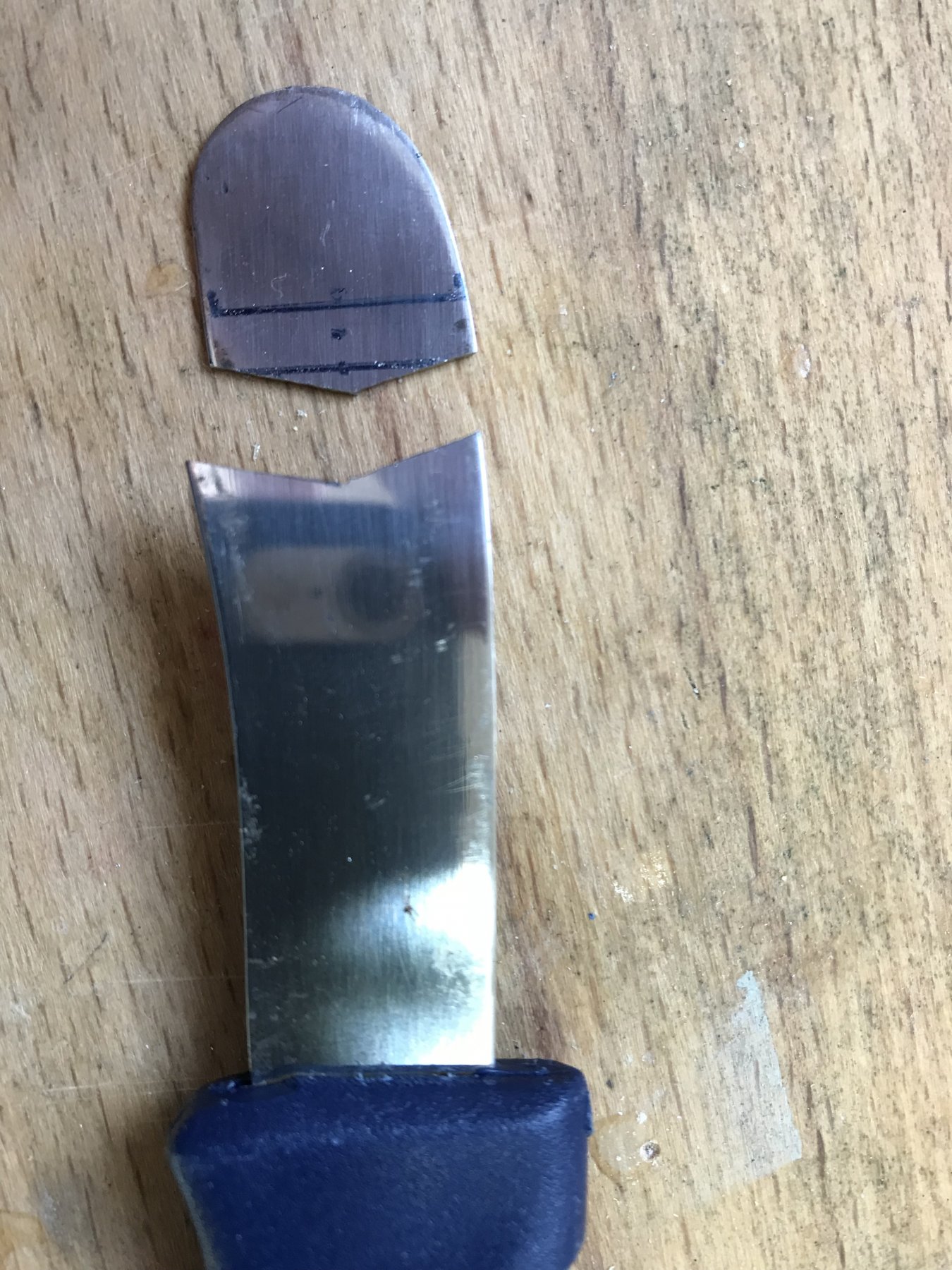
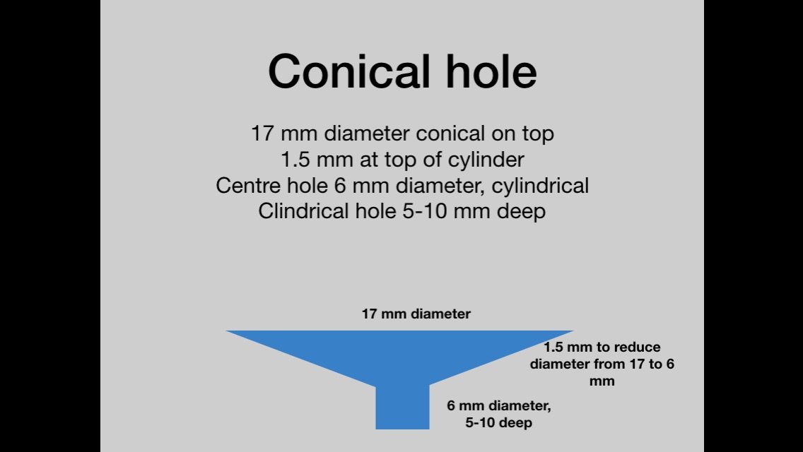
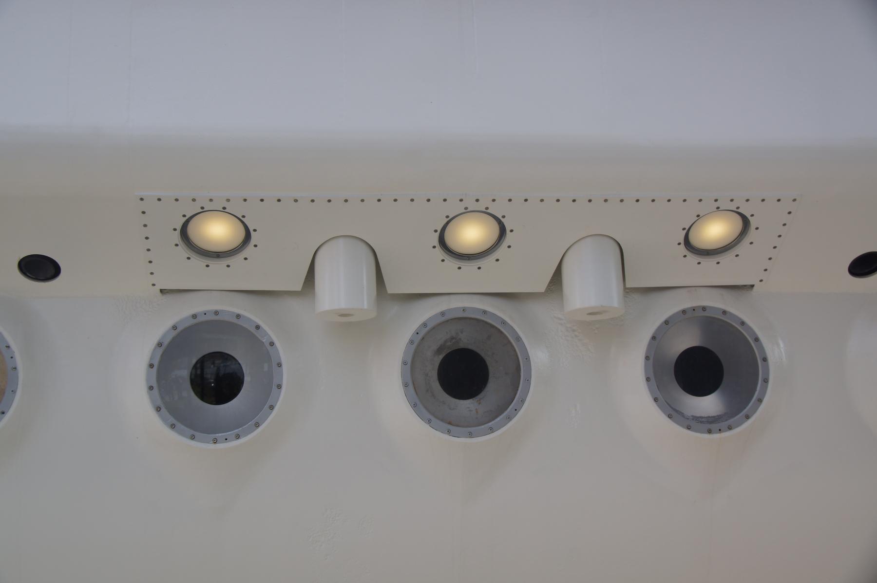
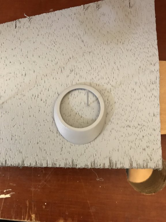
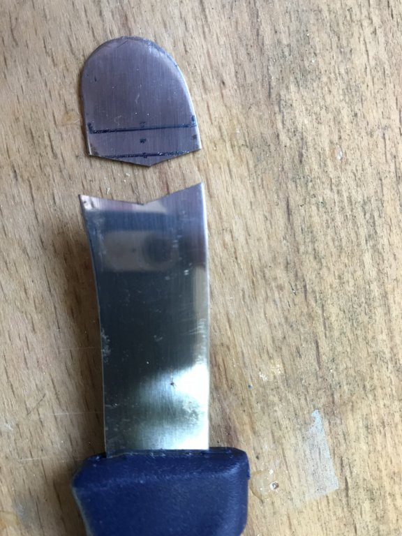
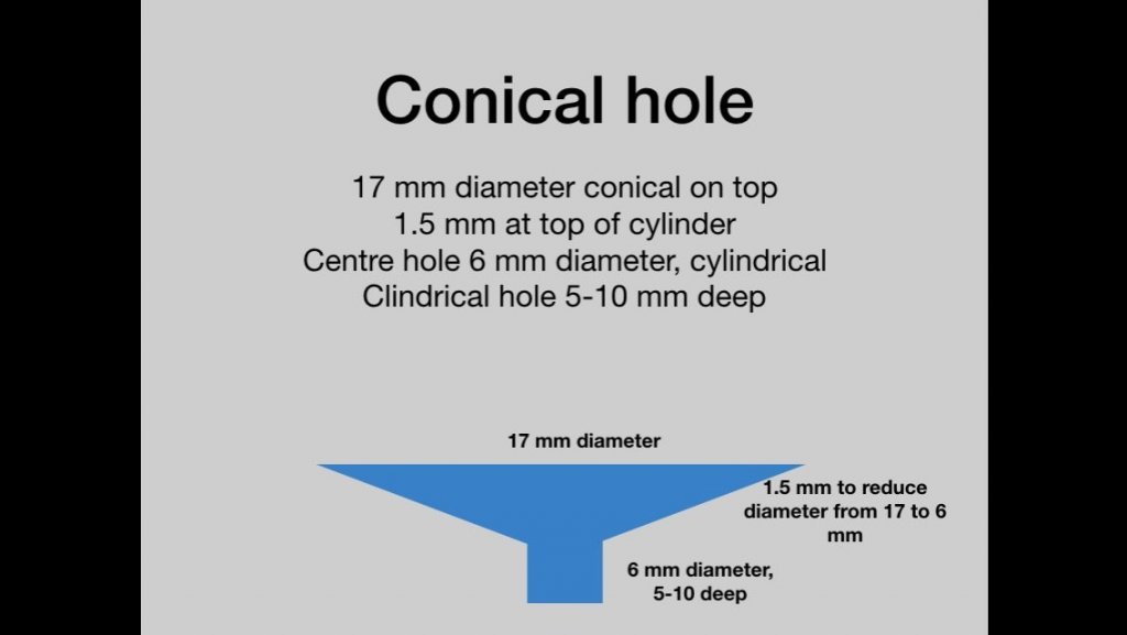
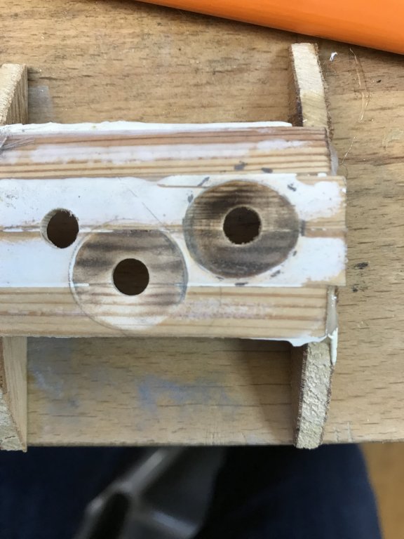
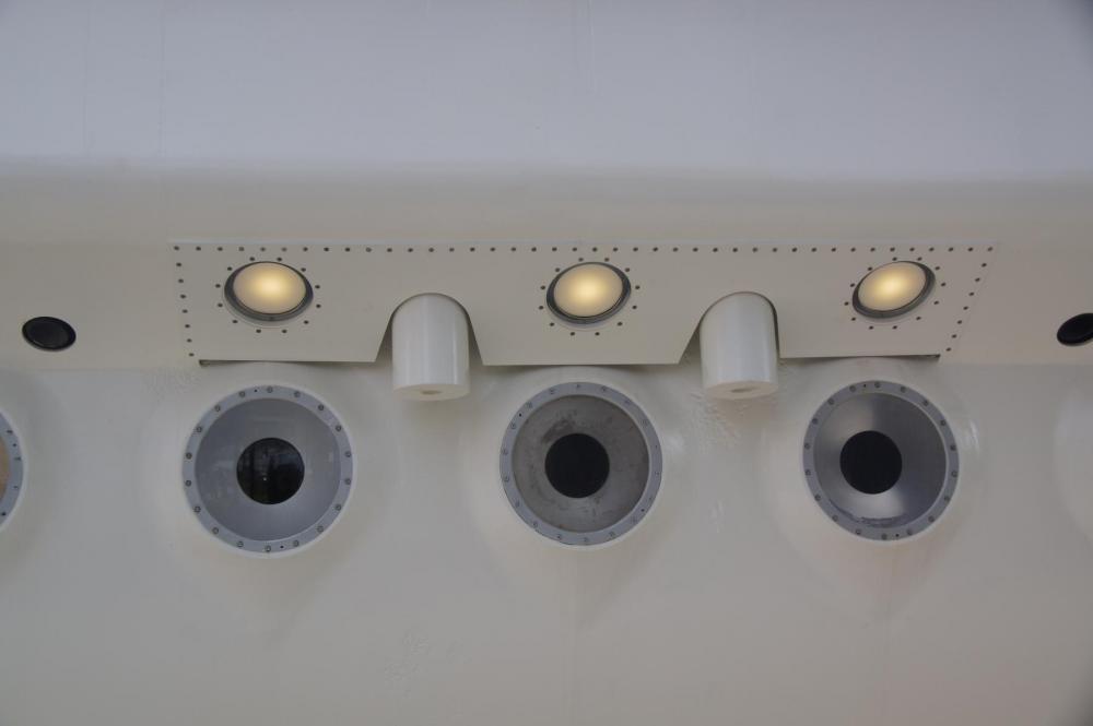
Hello all, as you may have noticed, I’ve had a long “dry” period. On the one hand I really could not figure out a way to create those 40 identical windows in the Auguste Piccard, and on the other hand I also took up another hobby - long distance running - which took up a lot of time. But the itch was often there - how do I solve this technical problem? so back to the windows. Up in this thread is a closeup picture of the windows, they are located somewhat below the heart line of the cylindrical hull, and are mounted vertically. That means there is a “structure” connecting the window to the hull which is different above and below the window. After much experimentation I’ve now come up with the following strategy - drill 6 mm holes in the hull - the actual windows - built a cutter to make this into a conical hole 17 mm round at the outside of the hull and 6 mm on the inside. I tried to make the cutter out of steel, could cut it in the right shape but could not drill two 0.8 mm holes through it to mount the cutter to a shaft. As I will use this cutter at 30000 rpm, i felt i meedeed the safety of two messing “rivets” to preventie the blade going airborn. So i toen Made the cutter from messing. Probably have to sharpen it after every few holes. - i used the cutter to drill some more holes in the “testhull” and it workshop, BUT, of course the holes are not circular due to me drieling with a circular cutter on a cylindrical part. Therefore that “connecting structure” I talked about needs to be made as well. And 40 times identical. - at this point I decided for a radical solution. I can 3D print these structures, which will give me a perfect round 19 mm windowsill connected to the hull. The conical hole will be closed with a 6 mm slice of copper tube, which is closed with transparent epoxy glue. Then I can pour the window from the outside. the 3D printer of course is not the problem, it’s the CAD that I will need to learn to design the parts. But eventually I found a free but sophisticated CAD program with huge numbers of online help videos (Autosketch Fusion 360), and after a few evenings had the part on the screen. The 3D Printer took 4 days to arrive from China, and the next day I printed my part. I’ve not poured a full window yet but at least I have a strategy and proof of concept. Pictures show some of the stages including the first two 3D designs and prints of the window strauctures (red), one double size of the other due to confusing radius with diameter !), the cutter, the finished bow of the sub and some of the holes for the windows Wish you all happy Xmas and much persistence and patience in 2018! Freek

- 55 replies
-
- 7
-
-
- auguste piccard
- submarine
- (and 2 more)
-
Hi Flip, you made a comment on my O-1 buildlog in 2014, indicaties you live in Vlissingen and might be able to fine Some images of het "dokje van Perry".
Ive built a stand and bought a transport case for the O-1, and now I'm interested in mounting a 40x70cm photo behind the model of the dockyard. Ideally it would be an early 1900s foto - I've seen many on internet but no high-resolution ones.
If if you happen to come across something like this or know where I could find it let me know! Appreciate it!
freek
-
Hi all, Progress has been slow throughout the winter, I've been training for a first half marathon which is in three weeks, but recently I started feeling like experimenting again. One of the key elements will be the 40 viewing Windows in a waterproof hull. here is what those windows look like. My plan is to drill the holes for the Windows, conically sand then out, then treat the hull with glass fiber and epoxy resin, and then pour the Windows from transparent epoxy resin. Here is a test piece with on the left the drilled and sanded holes and on the right the first test. I'm not very satisfied, the structure of the glass fiber is somewhat visible and I need to think how to create the very thin metallic ring around the window. Comments and ideas very much appreciated. This has to be a robust process, as I have to repeat it 40 times and differences between the Windows would stand out! Greetings, Freek
- 55 replies
-
- 8
-
-
- auguste piccard
- submarine
- (and 2 more)
-
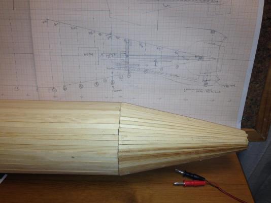
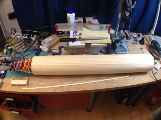
Another small update, basic planking of the pressure hull is finished, need to still make the domed bow but that can come later. I will start on rough sanding before impregnation with epoxy as part of the waterproofing. As part of the sanding the end cone on the stern with pre drilled hole for the prop shaft will be formed. The prop shaft will be made of a messing tube, in which are brass gliders placed, and a spring mounted shaft seal between the shaft and the housing. Exactly like I did for O-1, with the advantage that the whole thing is lubricated by water so no need to change grease. A propellor has been ordered from propshop (luckily it's a modification of an existing one and does not require a new mould), and also the first order for the dive system and bayonet has been placed with Norbert Brüggen Freek
- 55 replies
-
- 5
-
-
- auguste piccard
- submarine
- (and 2 more)
-
Like the O-1, the hull will be attacked with a saw and cut in two parts between which a bayonet closure will be installed! That's a ways down the line though.....I'm wearing a sports watch when I do that to monitor my heart rate...! Freek
- 55 replies
-
- 4
-
-
- auguste piccard
- submarine
- (and 2 more)
-
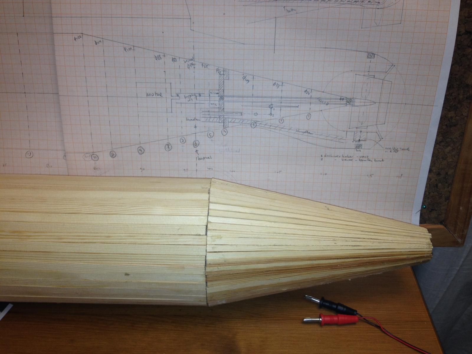
A small Update. The main hull is planked to a 75 cm cylinder and I started on the conical stern. The boat will get a hemispherical wooden bow, but I'll leave that open for now until the inside has been treated with epoxy and the Windows made. In front of the hull is a test piece for trying out ways to make the Windows. Greetings Freek

- 55 replies
-
- 10
-
-
- auguste piccard
- submarine
- (and 2 more)
-
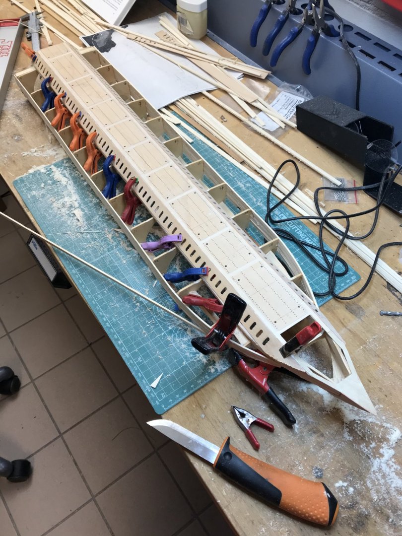
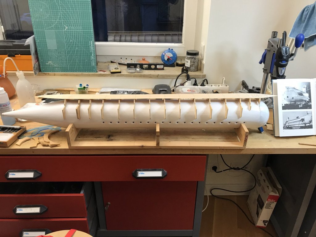
Thanks again for the interest and the likes. I started building a week or so ago. The start is great, the frames of the boat are perfectly circular, and most are identical in size. There is no real keel, rather two identical ones with notches to hold the frames. Oh, and neither is the keel, as will rotate the boat 45 degrees so that these are not at the lowest point. I want to keep the bottom of the boat open to put in some sensors to detect accumulating water and alarm. Pictures of course are clearer (hopefully) In this third picture extra planks were fitted on either side of the "keels" between each set of frames. That enabled me to make the structure very stiff and totally straight, without the need for mounting the boat on a building plank. I guess that only works with symmetrical hulls like subs! Also visible in this last picture is the half-franc from 1963 glued to the keel. I shipbuilding tradition going back centuries and supposed to bring luck - always welcome in submarines. Planking the frames is usually where the skill of the builder becomes visible. Not here! It's a real beginners-hull, no stresses, no bending of the planks, no shaping of them. Easiest hull in the universe (and that's good as it's only the second plank of frame I ever did) So far today's update, we're basically in real time now so I'll be slowing down some (and the Xmas holiday is over). The advantage of that is that any suggestions from all of you can be acted upon! Happy New Year, Freek
- 55 replies
-
- 17
-
-
- auguste piccard
- submarine
- (and 2 more)
-
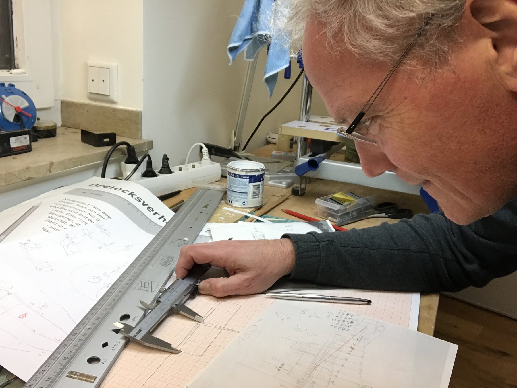
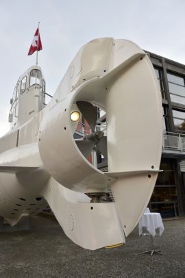
Thanks for the encouragement! Any project start with drawings. I found some sketches on the Internet in addition to the photo of the drawing in the museum. Then I made lots of photos of the boat itself in the Museum in Luzern. Based on that I have made basic drawings and rib plans on old fashioned millimeter paper (unbelievably still for sale!) Does that last picture say "Vancouver"? Yes after some years of tourist dives in the Lake of Geneva, the boat was sold, refitted for oil exploration type duties in the Caribean, and ultimately found somewhere in North America and brought back to Switserland. The basics of the build will be similar to HR Ms O-1, I.e. a plank on frame design, fitted with a bayonet ring to pull out the tech rack on which all electronics, pumps, motors and servos will be mounted. New for me will be the inclusion of lights, each window had a floodlight mounted in the saddle tank, then there were internal lights of course, and even the prop is illuminated by its own light - should be pretty in an evening event, but also LOTS of possibilities for leaks and shorts where wires go though the pressure hull. Below some of the sketches made from above materials! While doing this you also start to think of the sequence of the build, what to do first? What will be the most challenging (I think making the 40 windows in a way that they are clear AND leakproof! As well as the lights)? Also the rudder is integrated in the "jet-shroud" witted around the prop. I.e. Where the prop is fixed, it's shroud turns around the prop. And the pictures suggest the prop fits VERY snug inside the shroud...... I've made kind of a checklist of build items that I can continue to refine re-sort and add to.
- 55 replies
-
- 11
-
-
- auguste piccard
- submarine
- (and 2 more)
-
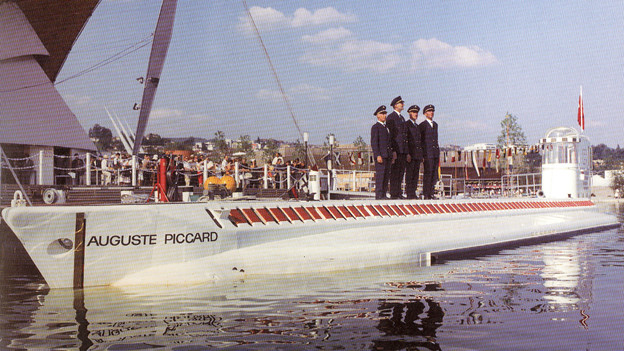
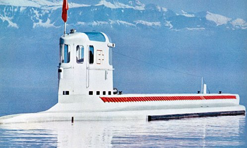
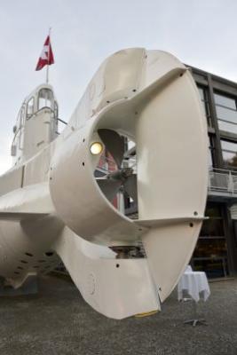
A few months ago I started on my new project, it will be my third radio controlled submarine. "Auguste Piccard" was built in 1963 by the famous inventor family of the same name, who also built the bathyscaphe "Trieste 2", which reached the deepest point on earth. Auguste Piccard was a electrically powered submarine able to carry 40 passengers to the bottom of Lake Geneva, where the World Fair was held in 1964. The boat is reported to have made over a 1000 dives, transported over 33000 passengers and was recently completely restored and is now displayed in the "Verkehrshaus" in Luzern. A 30 meter long submarine in a landlocked country! I took a lot of pictures of the sub in that museum during two visits (one before and one after the restoration). I was lucky to also be able to make some photos of a book on display with a schematic drawing. I've not found any real drawings, though there is an actual model sailing around in Germany - I'm not the first to build her. The model will be 1:25, making the model 1.10 meter and 10 kg. Here are some pictures. Freek


- 55 replies
-
- 14
-
-
- auguste piccard
- submarine
- (and 2 more)
-
Thanks for the compliments! The torpedoes have an elastic band, made out of flight rubber and oiled somewhat. With that I can apply 300 windings before the elastic band breaks. The prop is only 9 mm diameter and has a cm or so pitch - theoretically I could get 3 meter-ish, but as the Torpedo starts to counter rotate and has slip I'm getting between 1 and 2 meters or so. Amazingly the speed is very high and I calculate that the prop reaches 18000 rpm or so. Piet, your father was serving on some of the most modern subs of his time! But those deck tubes were rarely used! Freek
-
OK, this is my other boat, hr ms K-XVIII, or the predecessor to Piets O-19. I finally had an opportunity to test the torpedoes. These are rubber motor driven - have a great speed but not much range! But it looked great!
-
Ter lering ende vermaak! http://www.dutchfleet.net/showthread.php/16630-Proefvaart-en-overdracht-Hr-Ms-O-19?p=108753&viewfull=1#post108753 Fantastic how your boat looks. Freek
-
Piet, Your O-19 is really beautiful! Fantastic detail! I'm sure you've considered mounting the boat on the kind of blocks that she would rest on in a drydock. I've seen several models mounted this way and it adds nicely to the real circumstance. Of course, then you'd have to explain why a perfectly looking boat would enter Drydock...... Alternatively, how good are you building a reef? Freek