
FreekS
-
Posts
239 -
Joined
-
Last visited
Content Type
Profiles
Forums
Gallery
Events
Everything posted by FreekS
-
We all struggle with these calculations! there are some formulas that convert prop rpm and pitch into speed, and like roger I suspect at a few 1000 rpm the prop will deliver the max speed that hull can reach. The hard calculation is if the motor can deliver the torque to the prop under load. I suspect your motor can only do that if you use a gearbox (dropping Reva for more torque). Dropping the voltage on a brushed motor will drop torque. Brushed motors like to run at their rated rpm. but on a brushless motor which typically has ample torque that is exactly what you do. These have kV indications, being rpm per volt, so a 1000kV brushless motor at 12 volt delivers 12000 rpm (too much) so you could run that at lower voltage. You likely would need a 300-700kV brushless motor. I would couple a shaft and prop to your motor in a test rig, hook it up to a ESC and test if it runs and does not get too hot (and how much power it draws).
-
I’m not an expert on tugs but I estimate yours will be 1 meter long and weigh maybe 7 kg? (99 tonnes/24^3). I think that prop will provide massive power at under 5000rpm. Then you might consider a gearbox or drivebelt with a 1:3 reduction. Takes more space and risk of noise if not done well. you will need an electronic speed controller (with reverse!) and that unit and the motor can get really hot if prop and motor (and voltage) are poorly matched. You can cool them but that is wasting power. When you have the speed controller and a cheap servotester you can test the current draw and heat generation in a bath or sink. Alternatively you can buy a brushless motor which are much smaller for the torque (but take care that they need a different type of speed controller) sorry, this sounds difficult (or different from trains), but testing the voltage/current/motor/prop combination before building them into your ship is worthwhile.
-
Nice build! you will find (or calculate) that you will need quite a bit of ballast. Then lead-acid is fine provided it’s a sealed unit. looks like you don’t need much current. If 1,5A works (test in bath for waves produced with that prop, the 5Ah would give you three hours of run time. As there is no benefit for low weight and high currents of Lipo, stay away from them. I use them in subs where space is a premium. I also successfully used 2x10 eneloop AAA to get 12-14V. Big advantage (these are a special type of NiMH) is that these have no memory and hold charge perfectly over storage. Finally, Li-ion also has lots of very good cells (3.7V 5000mAh). If you make sure you speed controller has a low battery alarm than these are widely available and cheap. something you do need to research is the match of the motor to the prop. 90mm props will put a lot of torque on the motor. For brushed motors rule of thumb is that diameter of motor should be about same as that of prop. For brushless that does not hold, the have massive power.
-
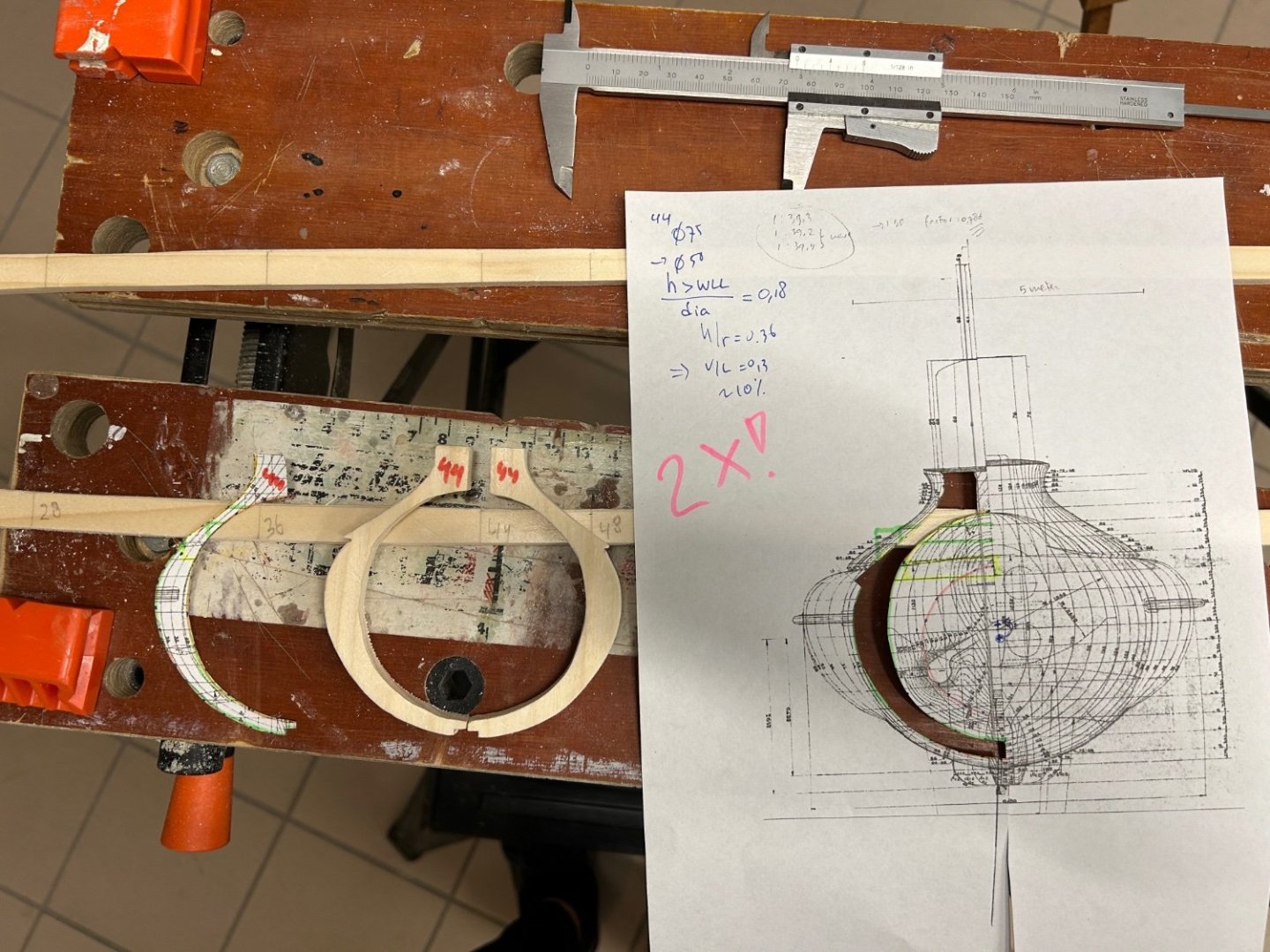
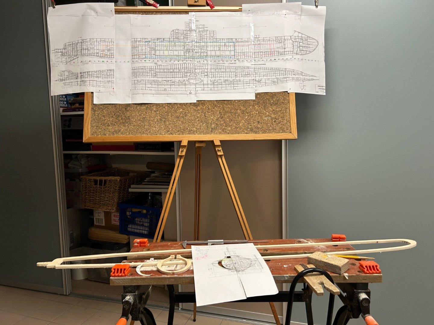
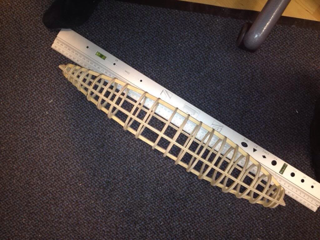
Started converting the concept drawing into a 1:50 plan. I’ve not made too many plank on frame models, normally I’d mount the frames on a build plank upside down. With this submarine planking has to go all the way around, so a build plank seems not too useful. I therefore cut a “keel/deck support plank” (no idea if there is a name for this) and will glue the frames to this plank. the keel is 8mm thick and the shown frame 44 also, as that is where the hull will be cut later to have access to the inside, so I need some strength in that area. I’ll likely double that frame at least. . . this was also sort of a test frame if I can cut the frame from the print, transfer it to both halves of the wood and saw it out accurately. Took quite some time - maybe I’ll try gluing the paper to the wood first. The other frames will be 4mm thick and after all frames are mounted I will connect them first with inserted short wood pieces to end up with a rigid (and hopefully straight) hull. I did that once before and it worked but for a shorter and simpler hull (so this was the basis of my Holland class sub, with much simpler circular frames)
-
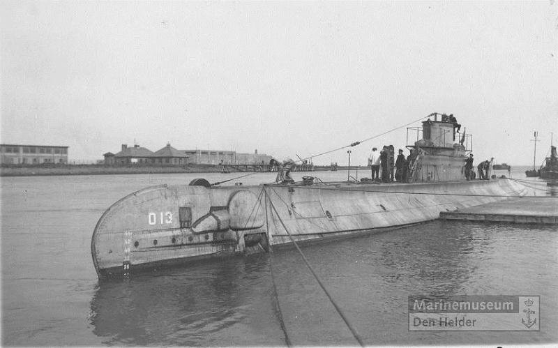
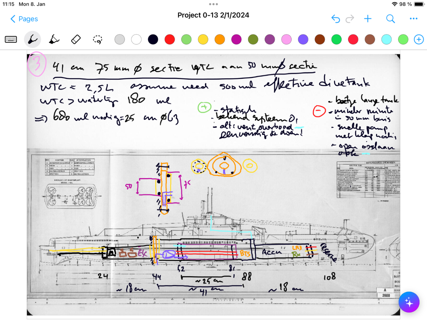
I’m just starting this new project. Netherlands started WW2 with 23 submarines, split evenly between Netherlands-based and Dutch East Indies based. Seven of these subs were lost. O-13 first saw action in the Spanish civil war escorting ships, and then escaped from Netherlands to England in May 1040 with many other boats. However, already in June 1940 on her second war patrol in the waters between Norway and Denmark she failed to return. To this day the wreck has not been found, but every few years there are searches with newer equipment. The most likely cause of her loss is being struck by a mine in a (now known) minefield along her route, but also attacks by German aircraft and a collision with a Polish sub are remote possibilities. This model will be radio controlled, and the boat will be in-between my Holland-class O-1 (the first sub in the Dutch navy) and the larger K-XVIII which fought the Japanese in Asian waters. Both those models still sail regularly and well. O-13 was part of a class of 4, at 60 meters in length and with underwater displacement of 750 tons she was suitable for coastal waters, but also travelled to the Dutch islands in the Caribbean and the waters around Gibraltar. She had 4 torpedo tubes in the bow, one in the stern, and two 40mm guns retracting into buns. No deck gun was installed and some of the 40mm guns were removed as the class had significant stability issues. I have the original build plans (which can be downloaded freely from the Dutch national archives), but photos, especially dock-photos are relatively rare. I plan to build a traditional plank on frame wooden hull, impregnated with epoxy and coated with woven glass. Inside will be a watertight compartment made up of several connected tubes to house the technology to fill and empty the dive tank, and to control the two props, rudder and diveplanes. I hope to include running lights in the wet area and also attempt to functionalisme the folding forward dive planes visible in the picture. Due to space constraints I will not aim to make moving periscopes and functioning torpedo’s for this model. In the end the model will be 120cm long, 13cm wide at its widest point, likely weigh 3-5kg, and use tubing of 50 and 75 mm diameter as water tight compartment. So far, I’ve been doing rough planning of the location of components, closure means, and rough calculations of the required size of the dive tank to achieve a realistic waterline. I’ve also started to convert the build plans to individual frame drawings (taking into account the thickness of the hull planks (2mm) and the need to mount the frames on a build plank). Needless to say - this will not be a quick build!
- 97 replies
-
- 10
-

-
The propshaft has a proven simmerring seal. There is no evidence of a leak there. I do expect some leakage where the lines to the rudder go through the hull, especially with motor in reverse. But some grease keeps it out pretty well. thanks for all the likes, I’m starting to think of the automation of the Davit now….!
-
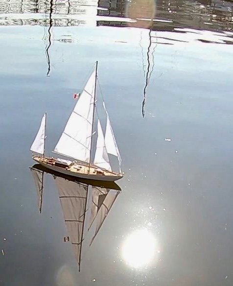
sails well - steering ok, there was about 100ml water in the boat - so I’m doing some more epoxy treatment. Needs a crew though!

-
fantastic build! I had not seen your build log! I only saw one in an Italian forum! Mine is RC as you say - still learning how to sail her!! I have not done lettering on mine yet - if you have a decal be really interested!
- 84 replies
-
- 1
-

-
- Corsaro II
- Corel
- (and 1 more)
-
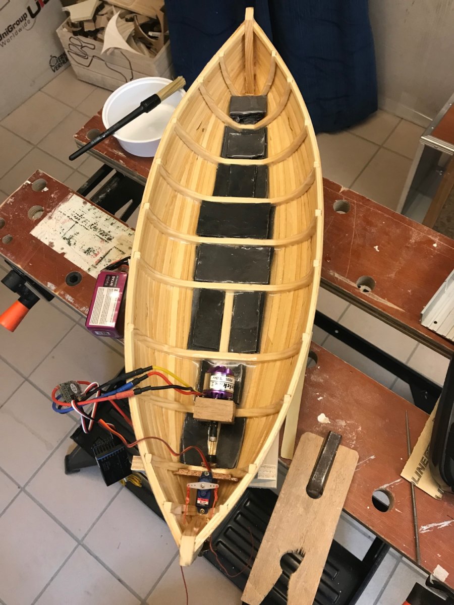
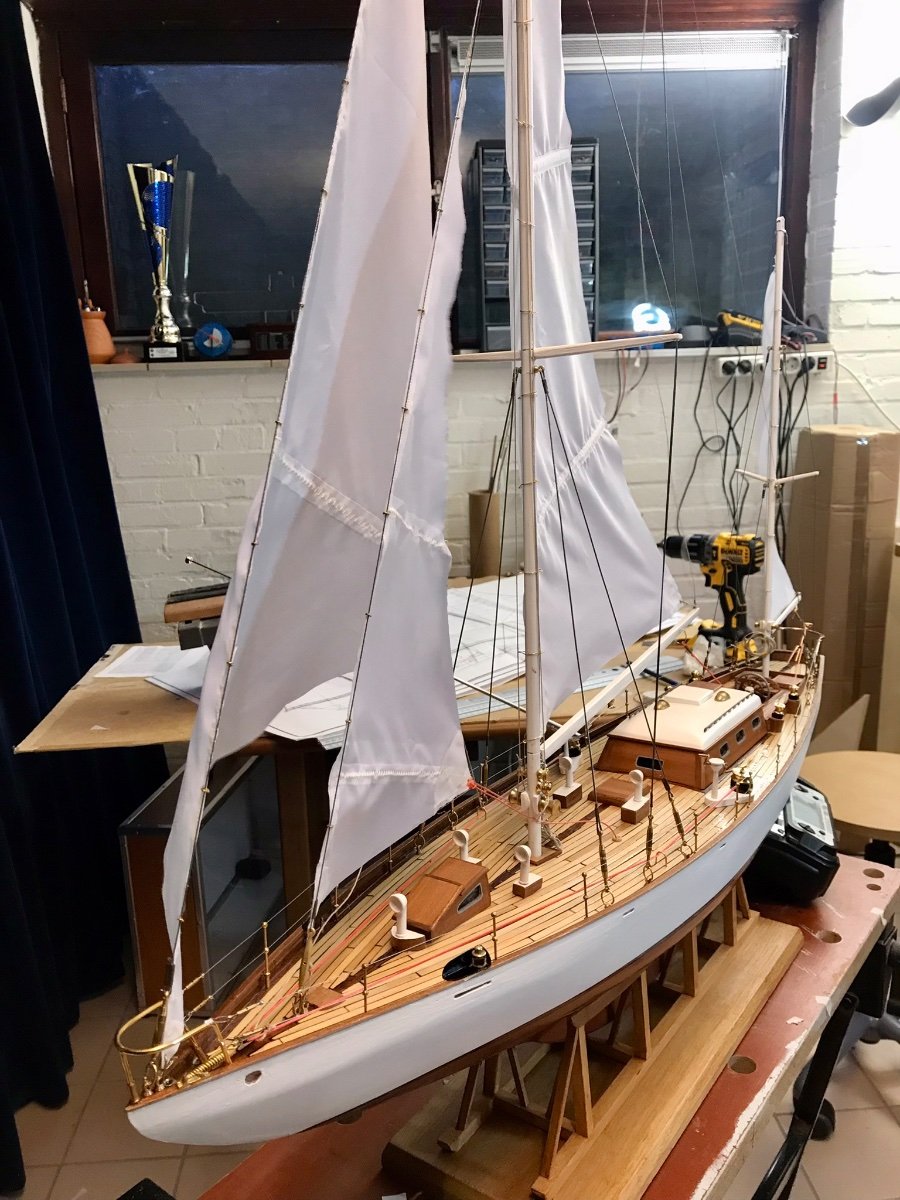
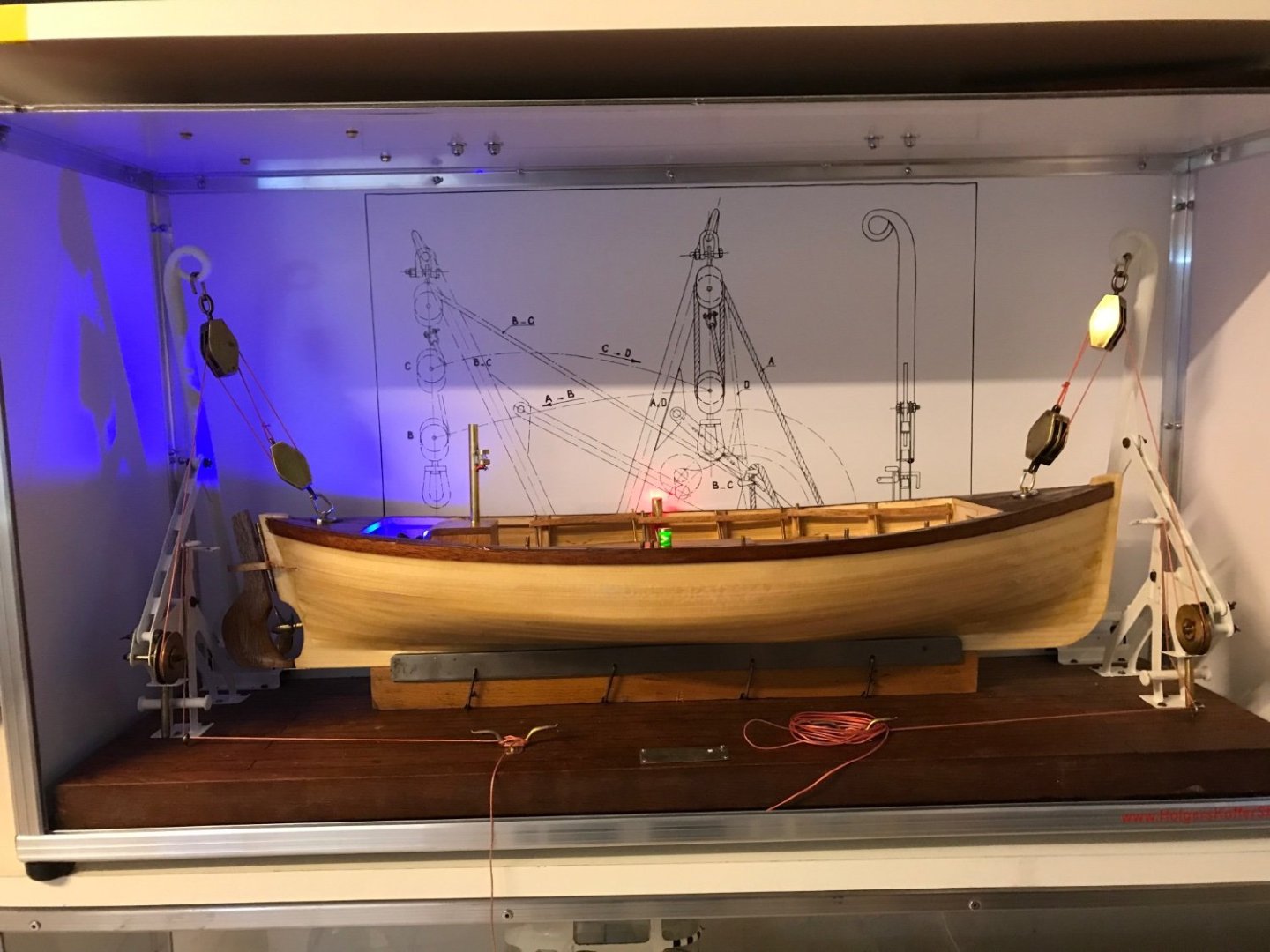
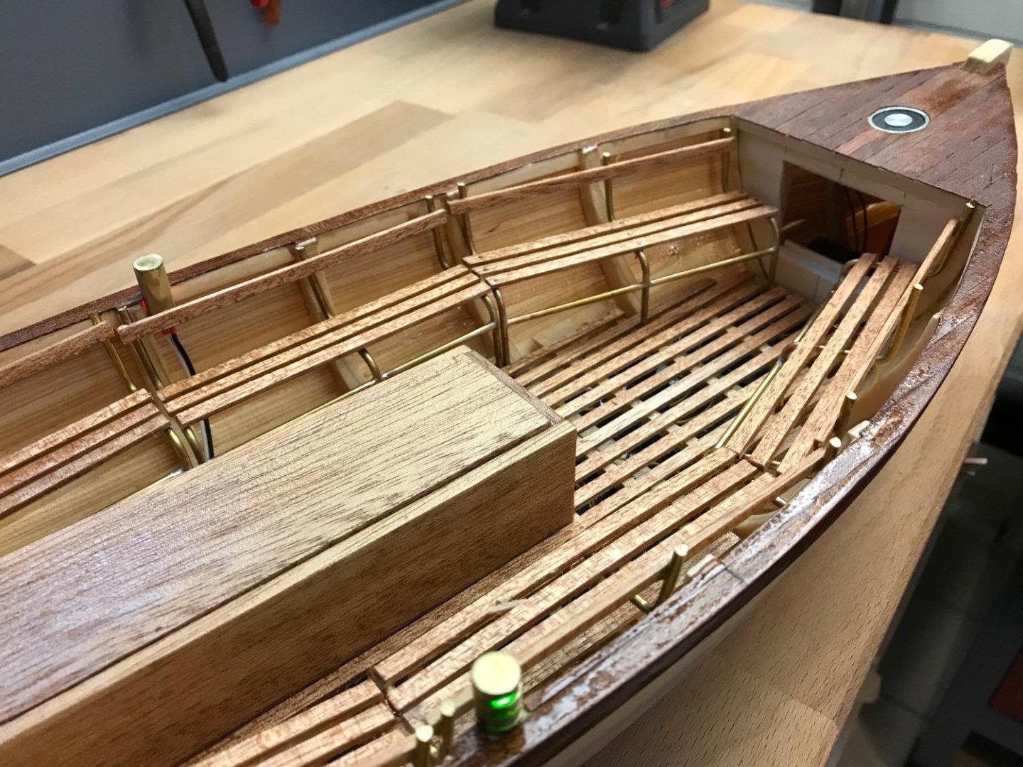
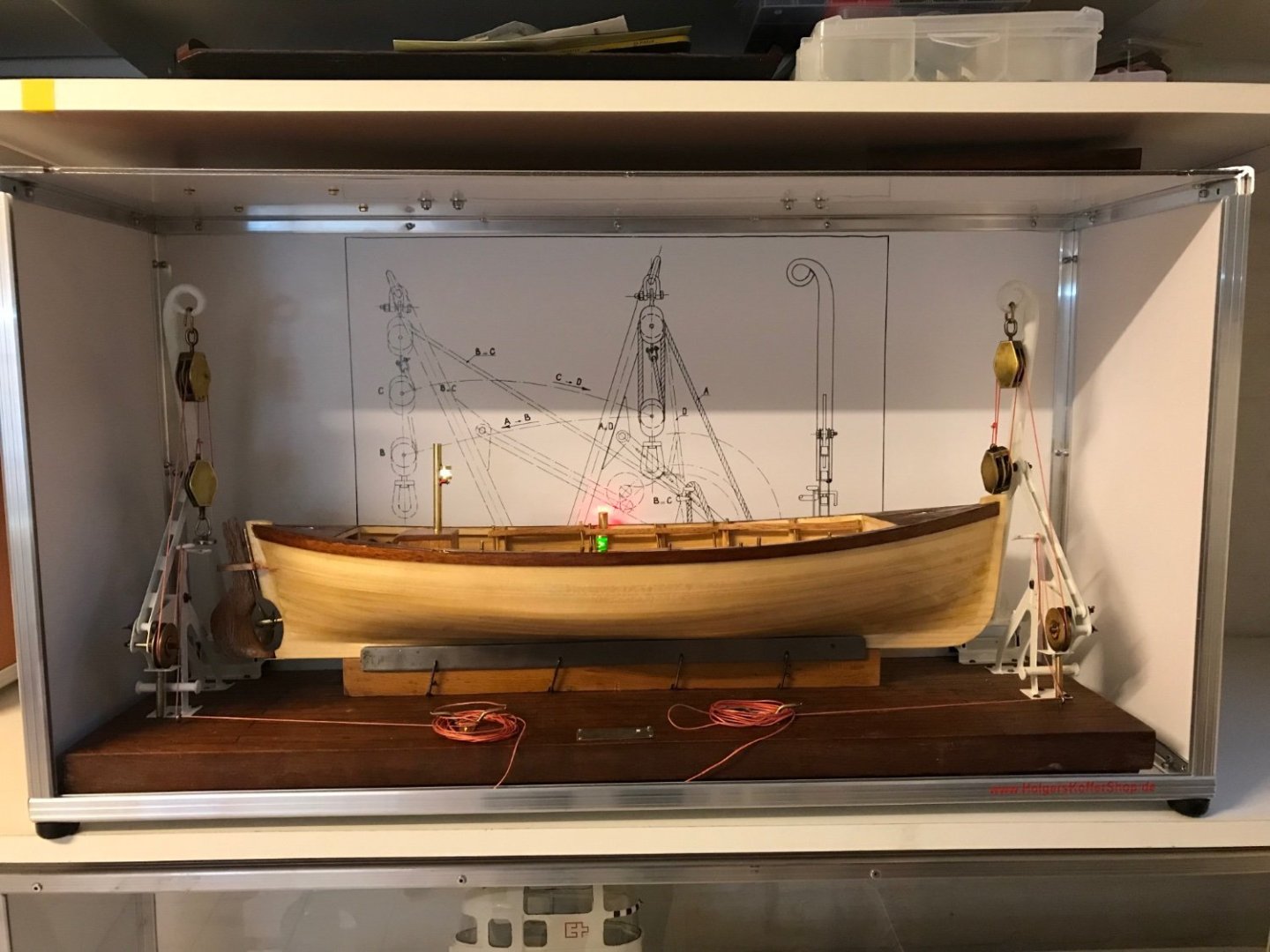
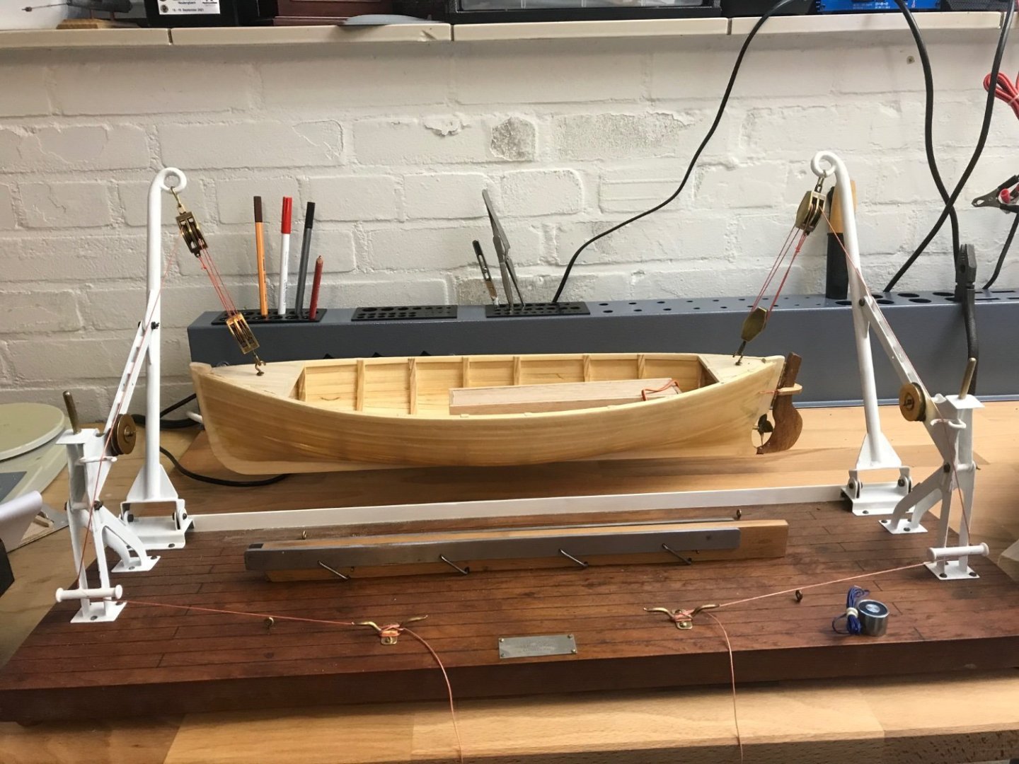
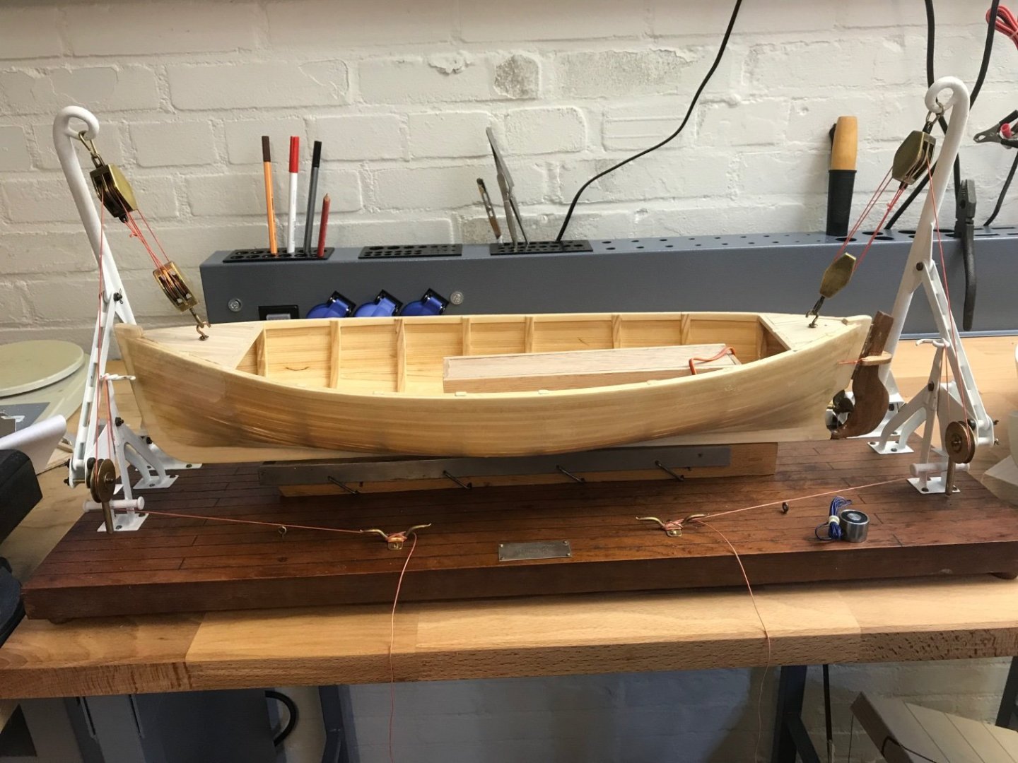
Progress on the lifeboat continues. The electromagnets are installed under the decks - they can unfortunately not be covered with thin veneer as this reduces their force dramatically. I did add some hardwood along the sides and used veneer on the decks. Cracks were finished with epoxy containing some hardwood sawdust. inside the boat I used some lighter hardwood for the floor “racks” and the benches. Navigation lights from some brass tubing and these are always on while the white top light can be switched. the magnets are rated for 2,5kg each (under ideal conditions) at 6V. I’m however driving them via a relais at 10v (3S LiFePo). They do get warm and I need to ensure they are not on too long. So I installed a blue LED in the dashboard to signify when the magnets are powered and the boat can be lifted by the davit. Here the boat is connected to the davit in its case. and the magnets release when they are switched off. boat is ready for first test tonight - then some more details can be added and I can start to think how to control the davit raising and lowering the boat from the transmitter - without losing sight of the fact that this davit design was manually operated and not powered.
-
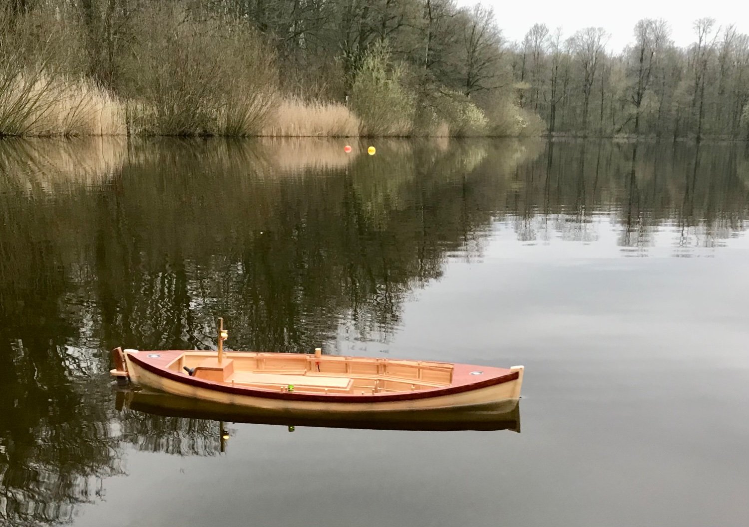
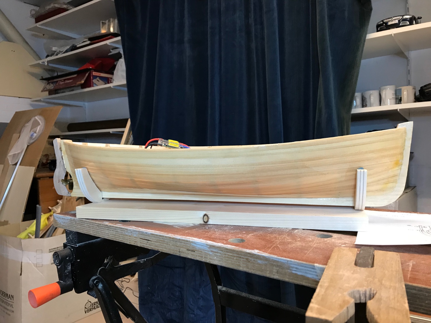
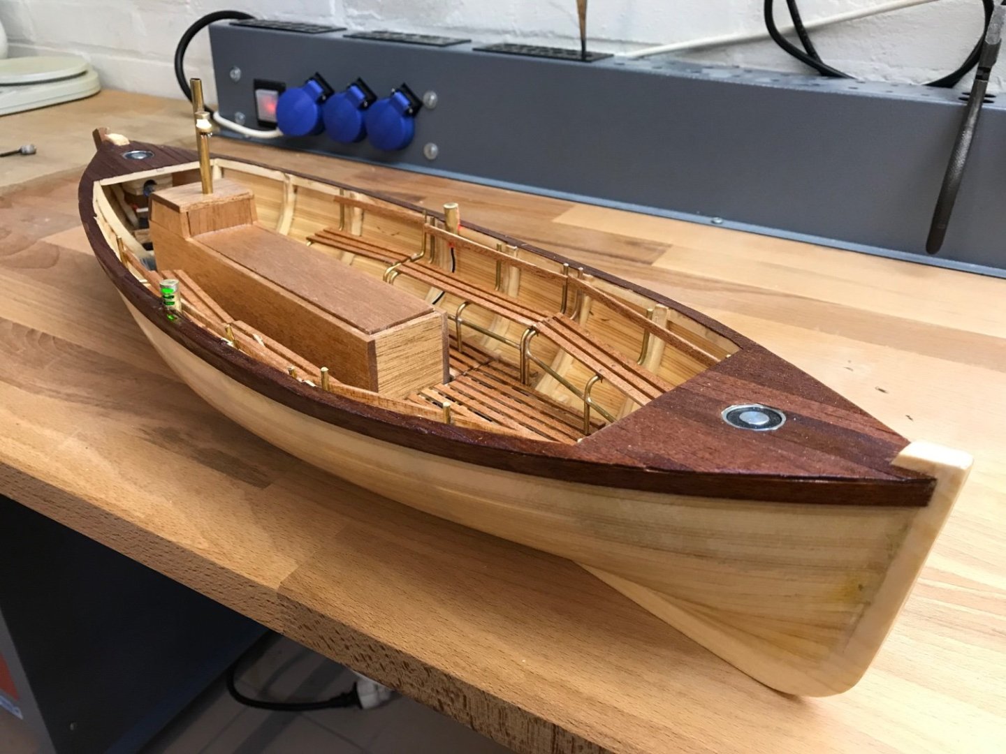
Boat has been ballasted with about 1 kg lead plates - glued with epoxy. Motor mount and rudder are functional. I made the boat 3cm smaller than it’s static predecessor - to allow some room for the rudder. after planking the foredeck and aft deck I could test where to put the mounts to hang it in the Davit. The not has 5mm rim in either side but swings out nicely. In place of the hooks in the decks will come two electromagnets that can each lift 2.5kg and consume 250mV at 6V (visible in foreground).

-
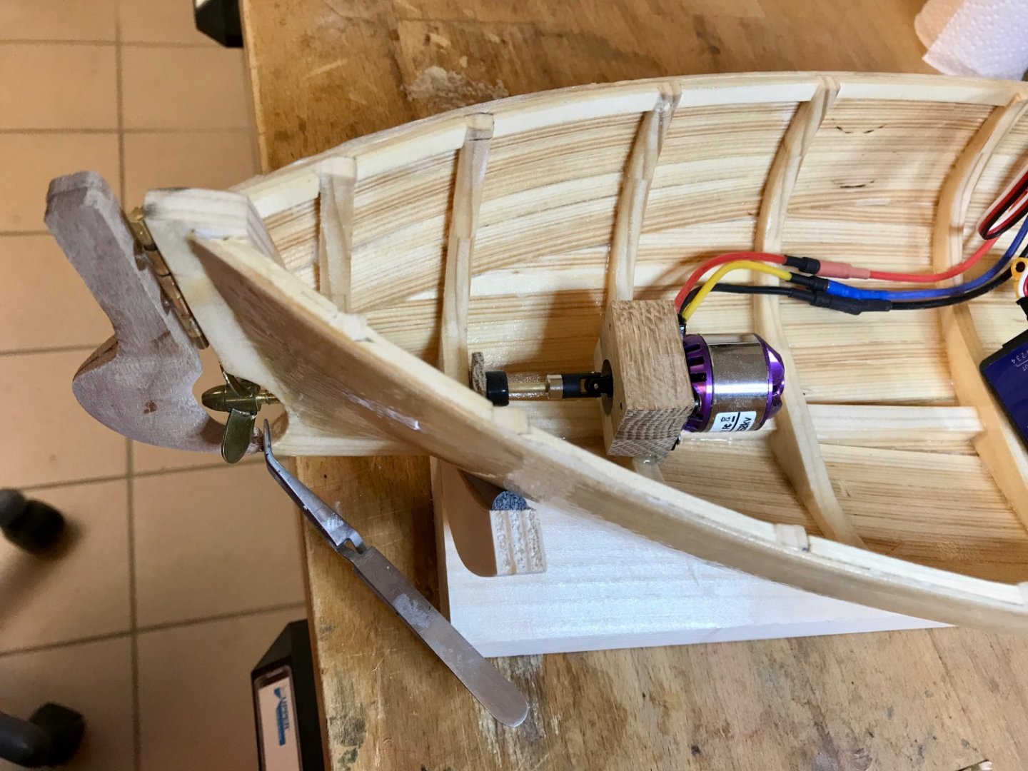
I’ve filled some of the gaps with small pieces of wood and a bit of “liquid wood”. then applied an epoxy layer with a layer of 80g/m2 glass fabric. This was followed by another two layers of epoxy and one inside the wood filled did discolour a bit with the epoxy, but I think I will leave the hull as it is instead of painting it. I installed a small brushless motor, a couplet and the axle connected to a 40 mm diameter brass prop. rudder is made from two sheets of hardwood glued together and shaped with file and sandpaper. I’ll need to make two small holes in the hull to drive the rudder from a small servo. that will be the time for a wet test to see how much current the motor draws, how much ballast to add and if the boat is watertight…

-
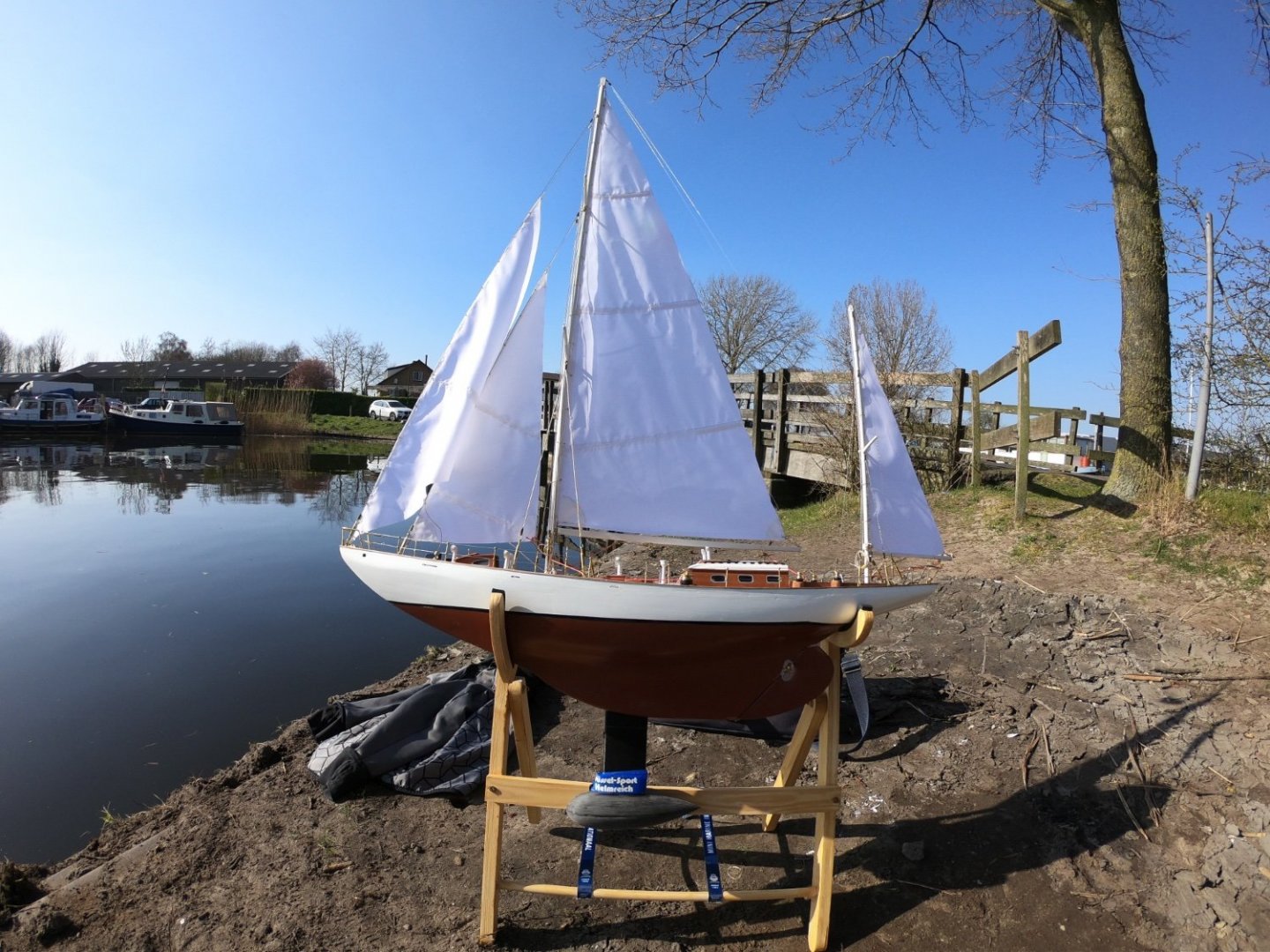
Hi great looking boat. Note the ballast scales to the power 3! So your 940kg ballast becomes 1,5kg at scale 1:8! you need to get that weight as low as possible in, or even below the keel with a “false keel”. See my Corsaro 2 build log for example. You also need to build the whole boat and especially the rigging as light as possible!! ill definitely follow this!
-
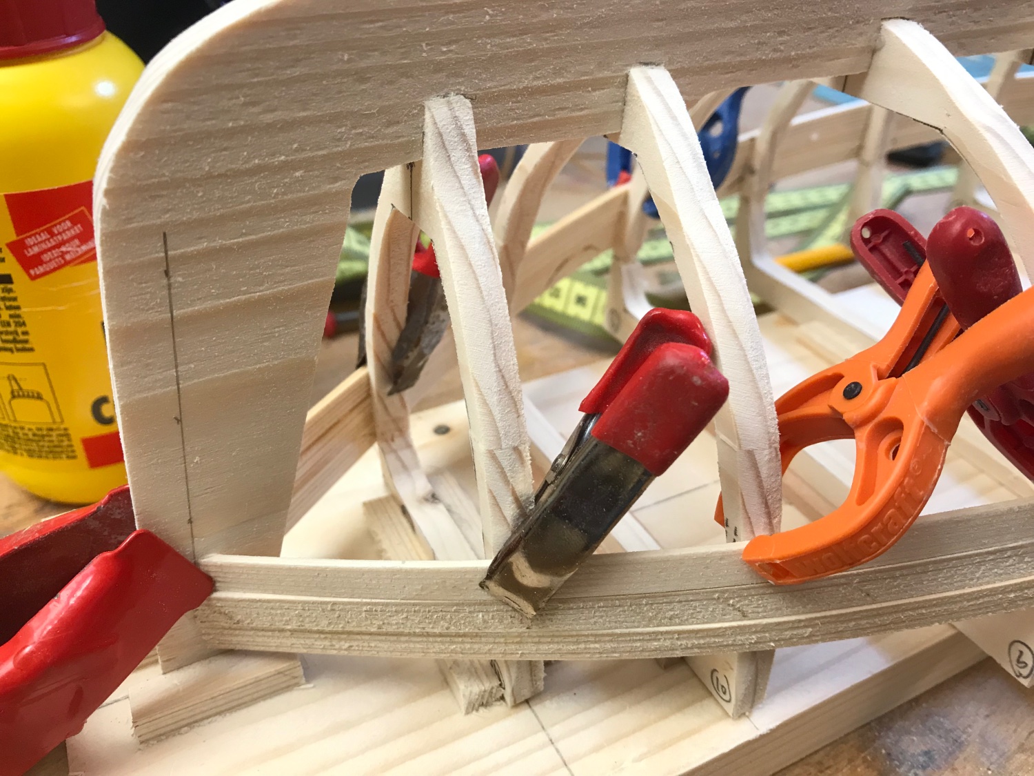
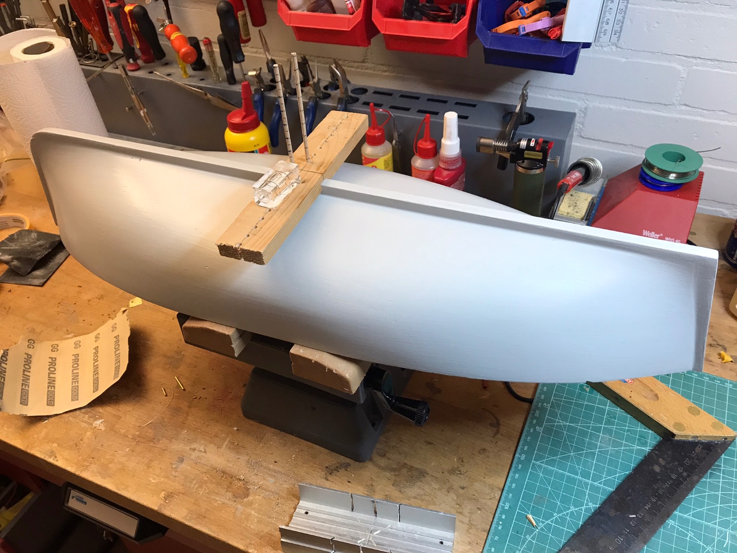
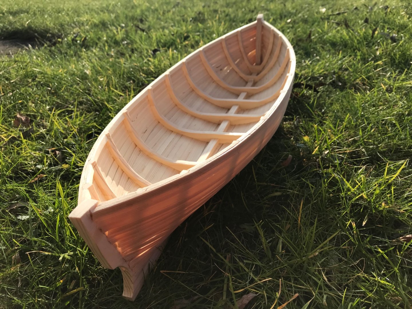
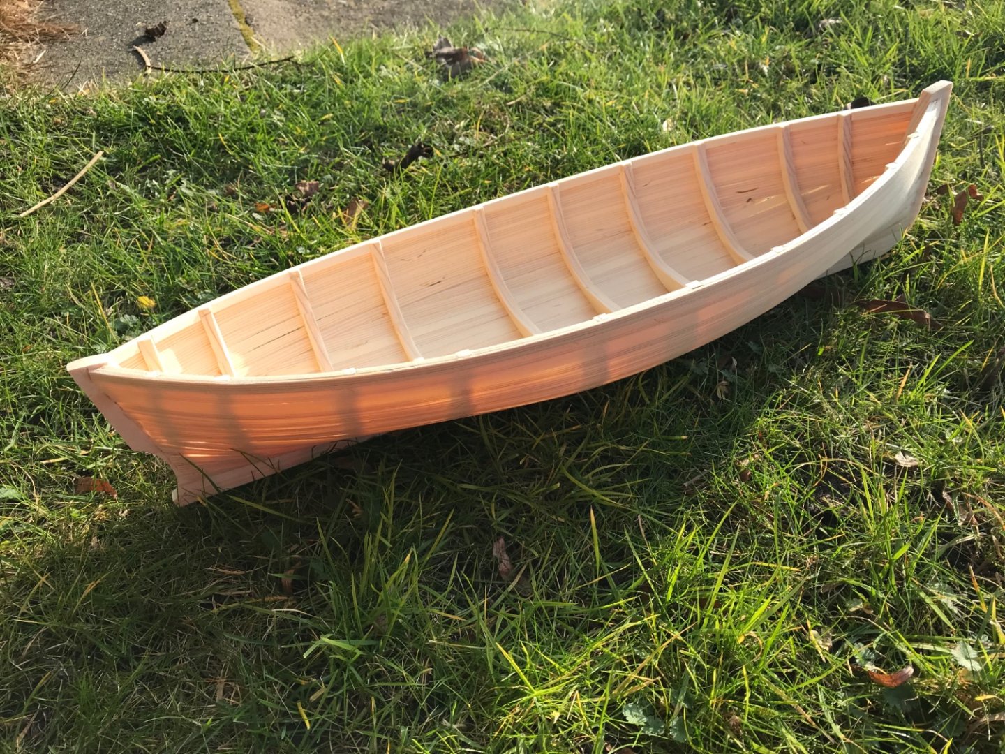
After first sanding of the outside I’ve cut the boat off it’s build plank to sand the inside. Surprised to weigh in at only 200 grams! The planks are only 2 mm thick (before sanding!) and the sun shows how thin it is!! I connected the tops of all frames with two more sets of planks - looks OK and strong. Plan is to use filler, epoxy and glasfabric for strengthening - not sure yet of the order!
-
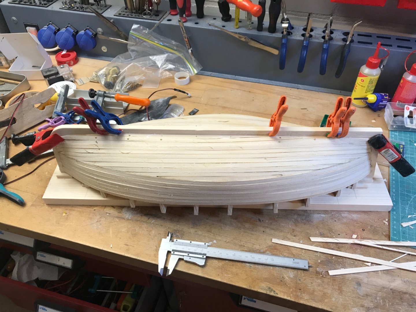
Here is the frames on the build plank, and the start and finish of the planking. Lots of sanding is next, and coating with epoxy

-
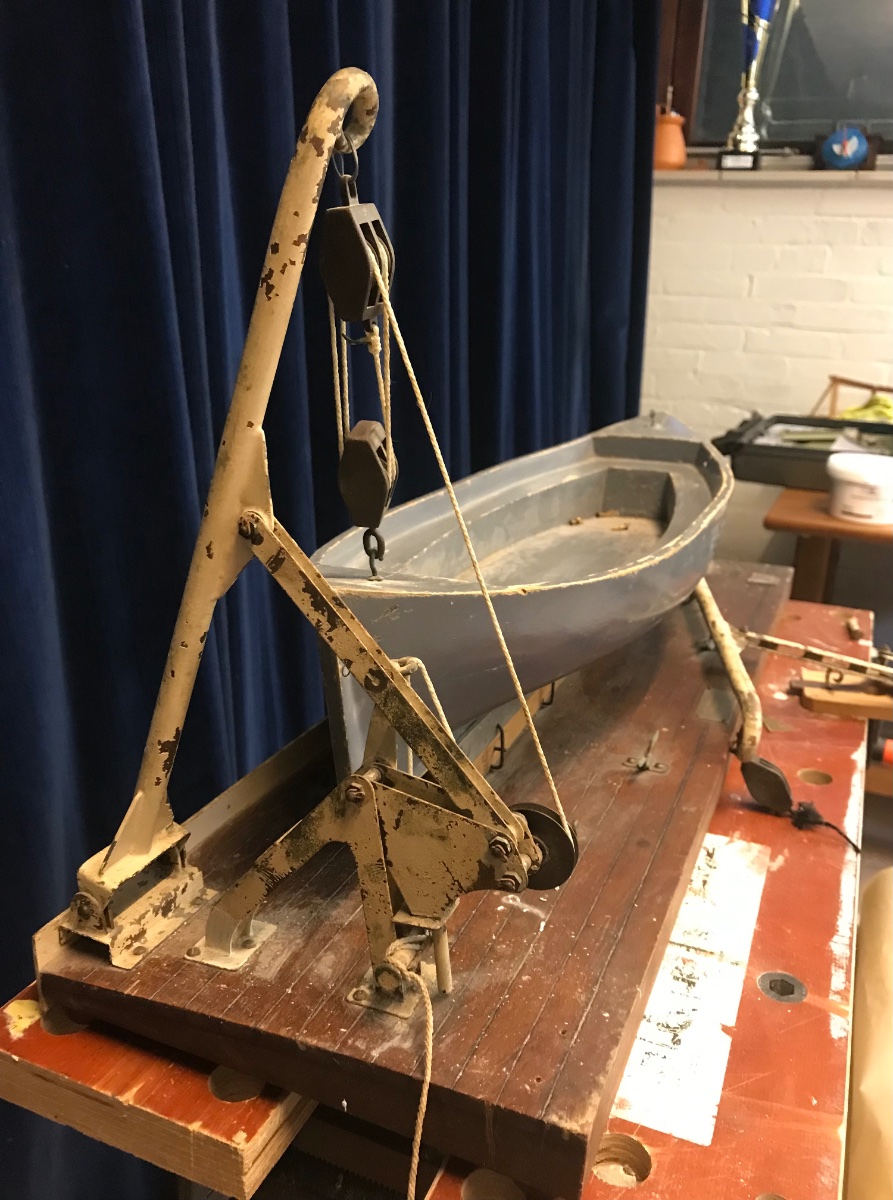
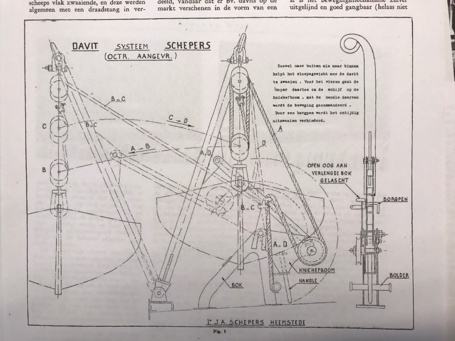
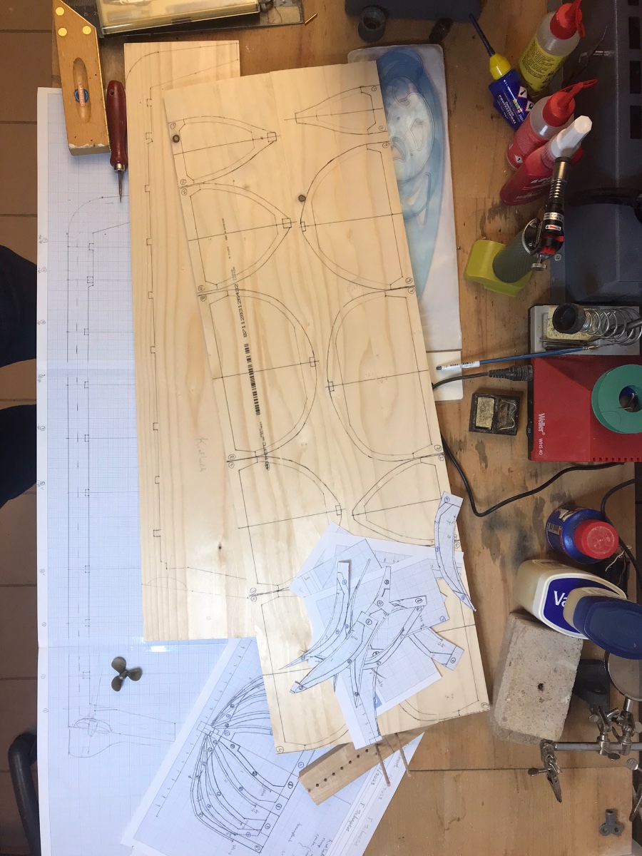
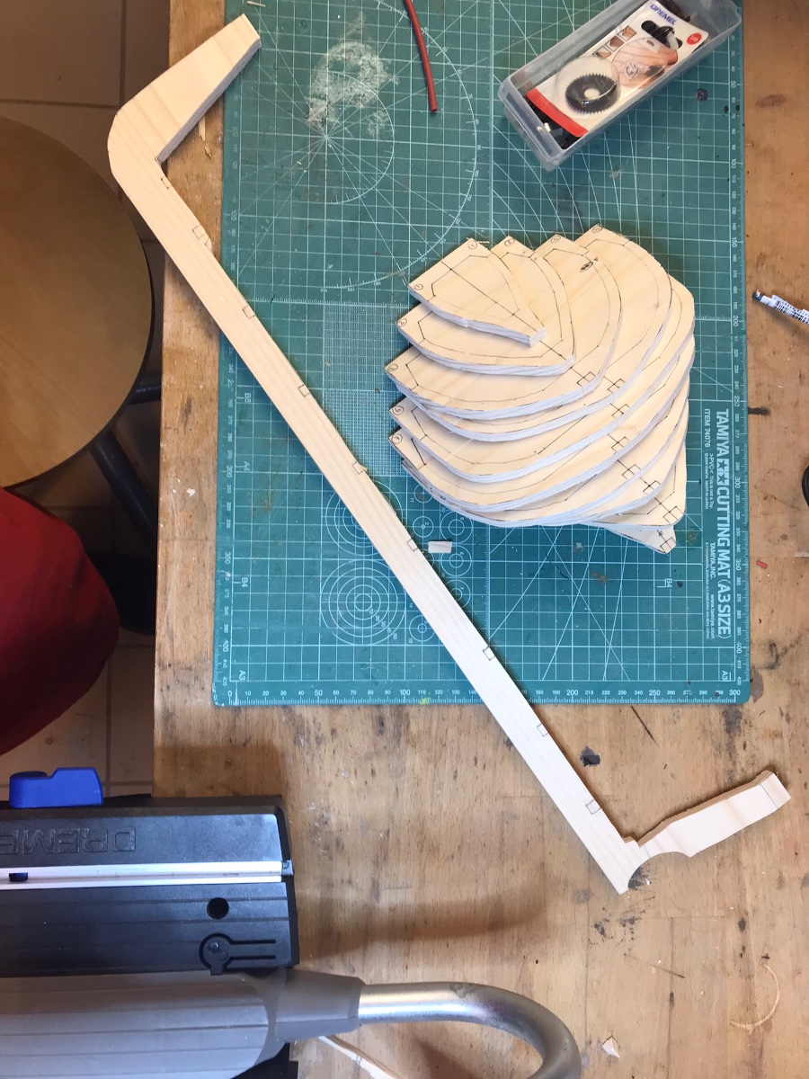
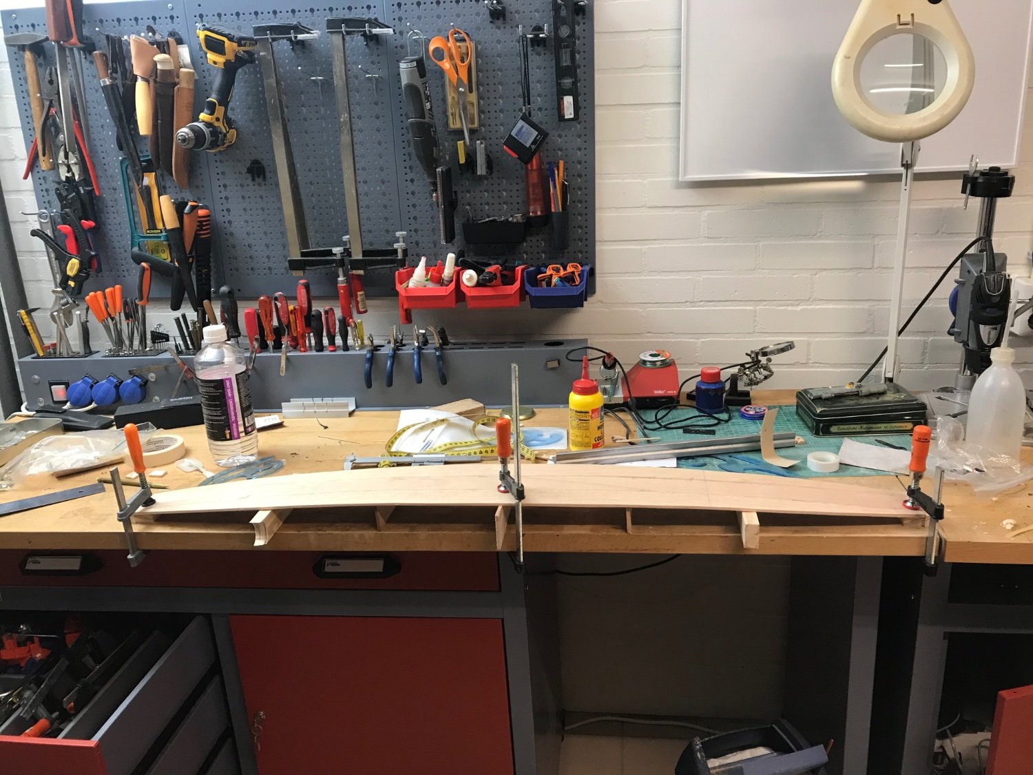
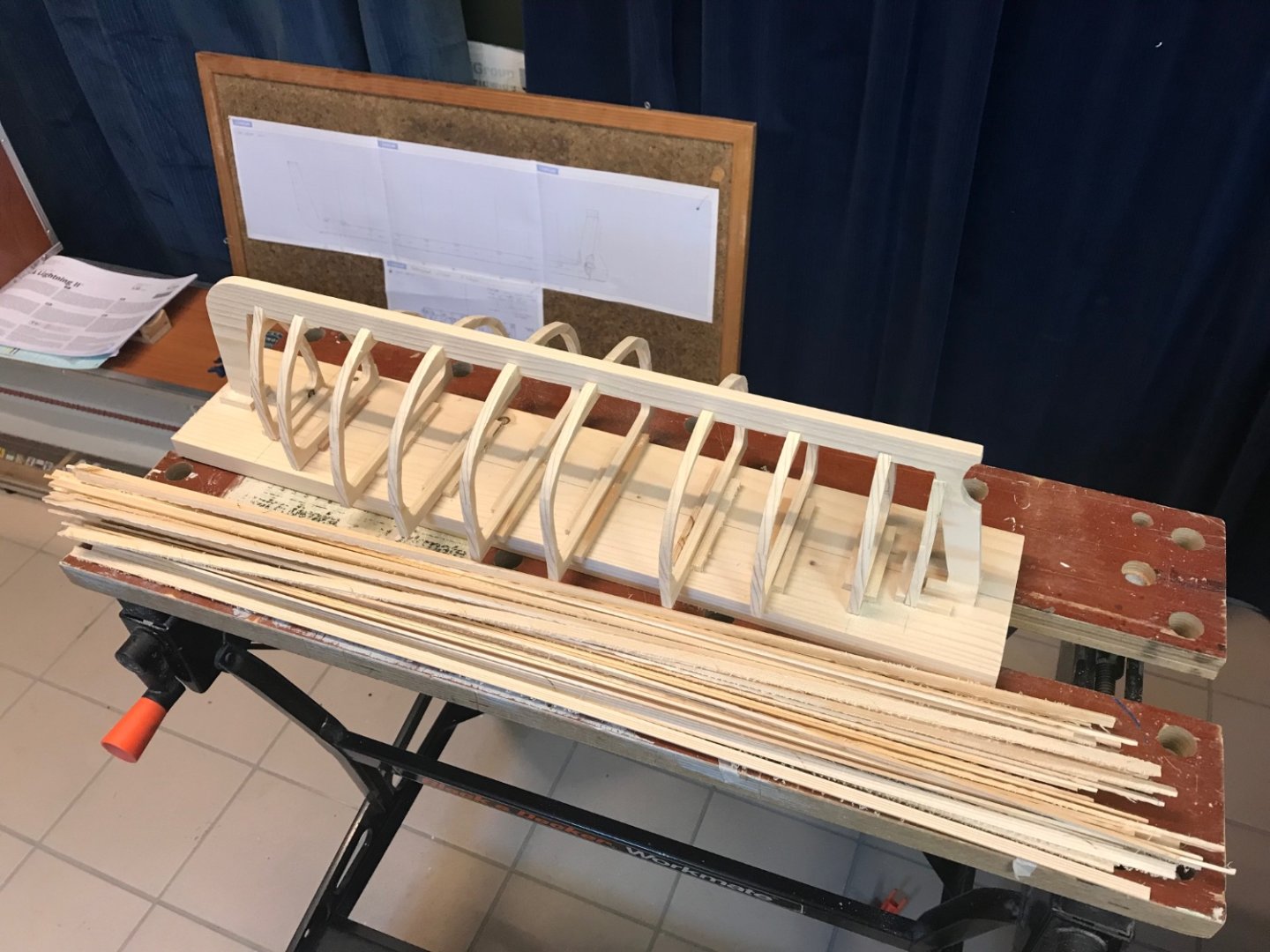
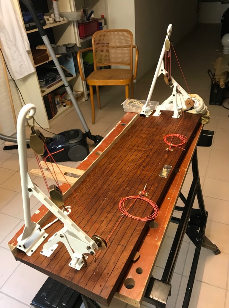
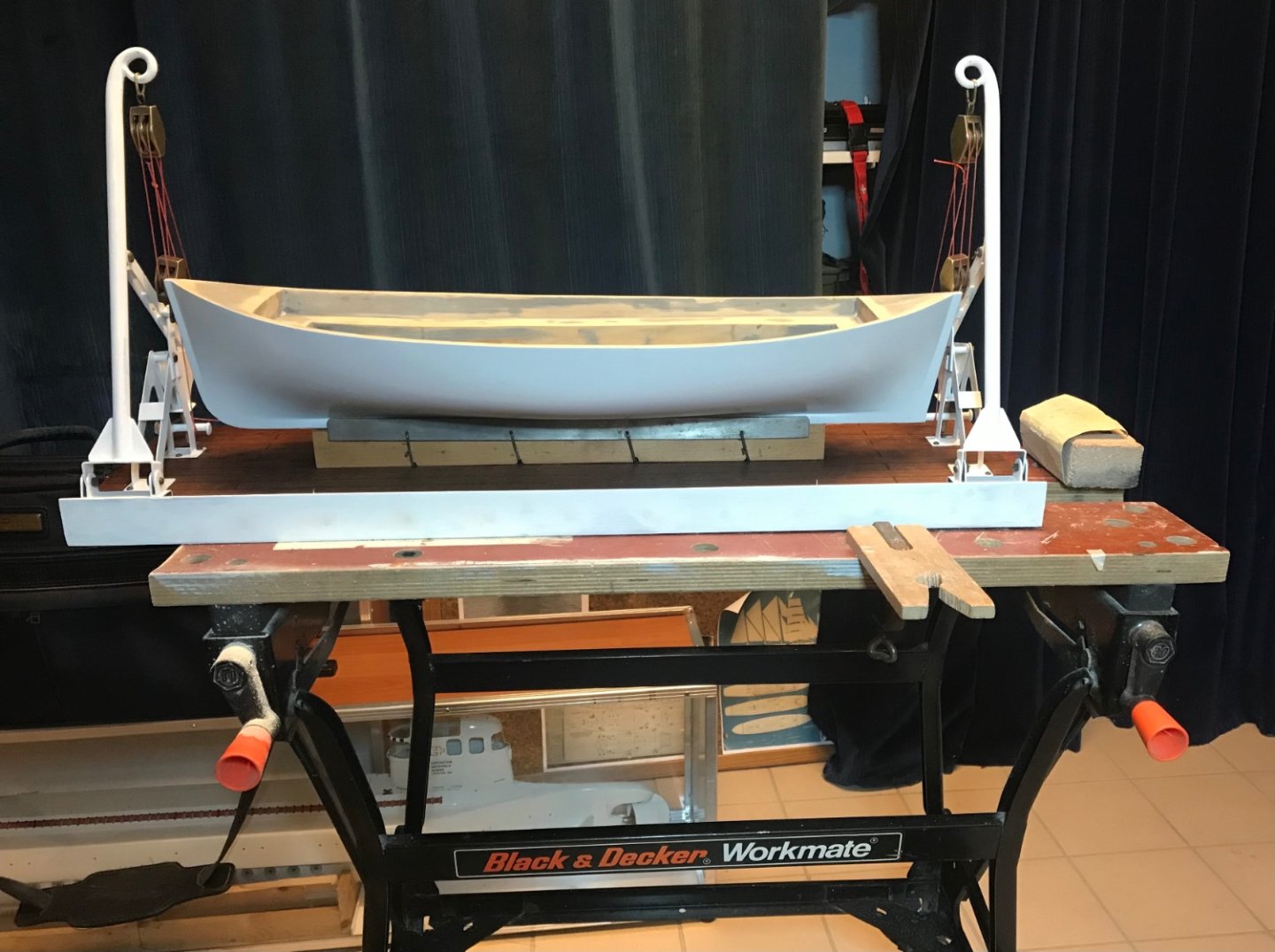
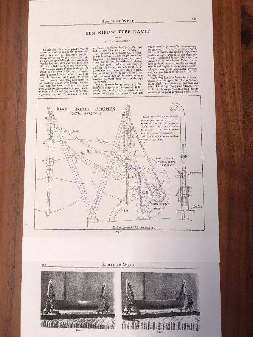
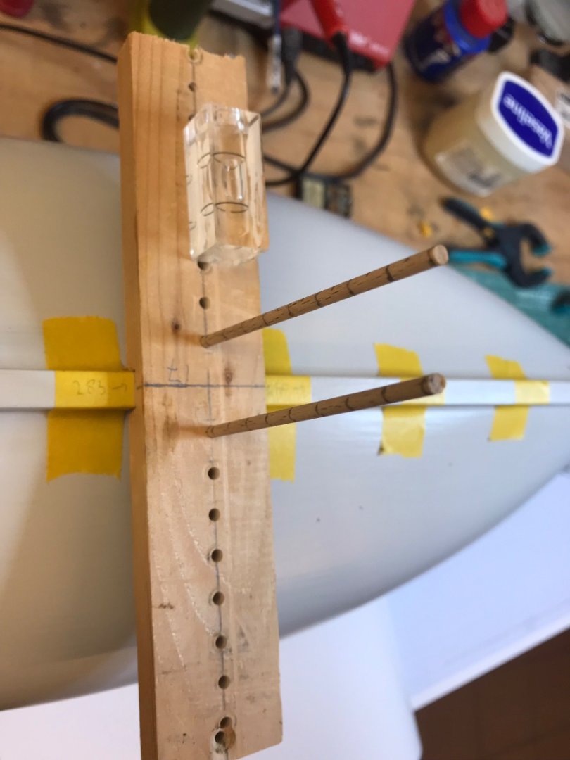
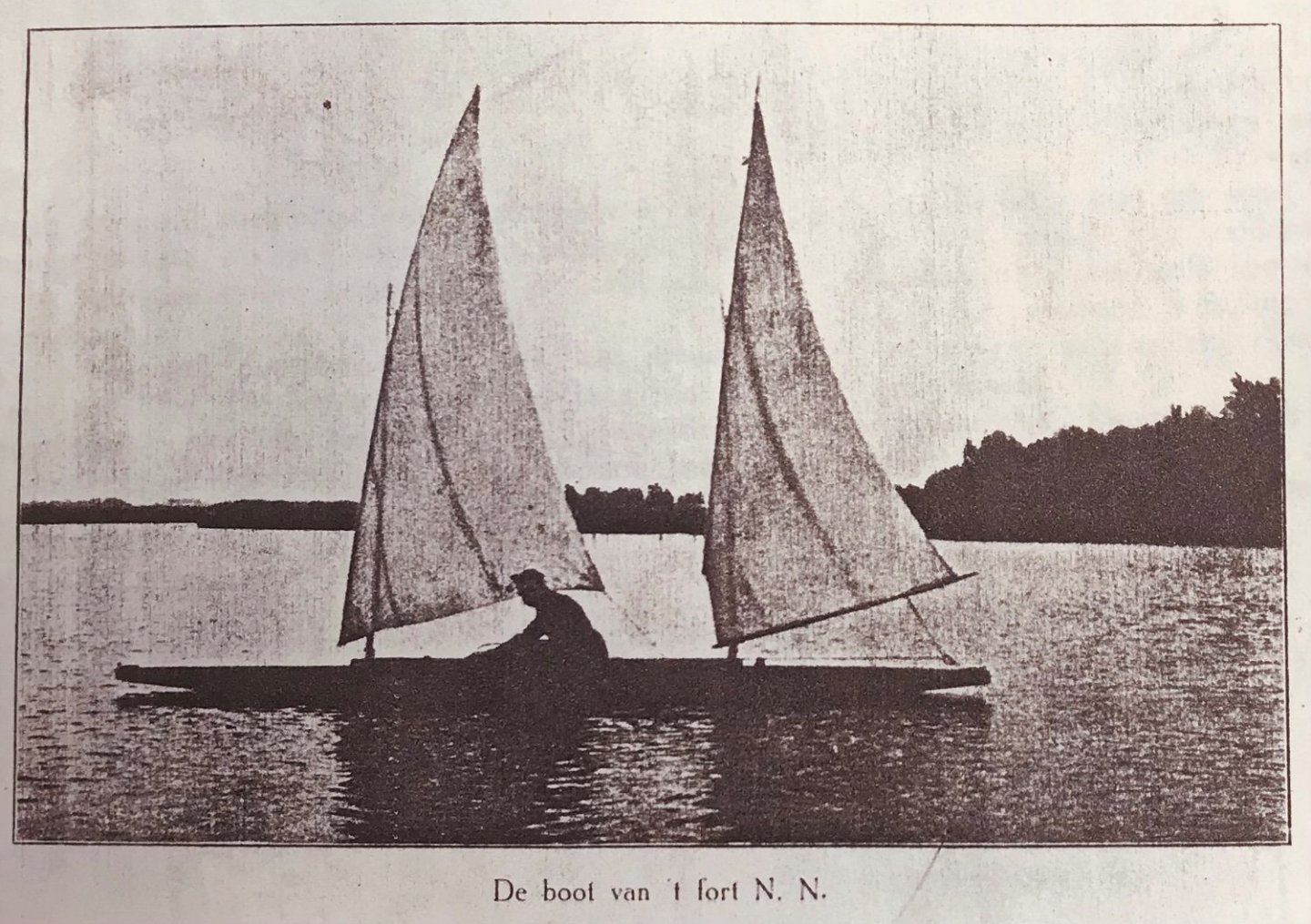
This winter I’m working on a “grandfather” repair and renewal project. My grandfather was shipbuilding engineer, and was drafted in WW1, spending the war in neutral Netherlands on one of the fortresses of the defence of Amsterdam. That’s where my last project came from. From the 1920s until the end of WW2 he worked in Dutch East Indies (Indonesia) for a shipping company. In 1947 after repatriation to Netherlands he filed a patent on a method to launch a lifeboat from a davit through a clever use of a pivot. Two crewmembers each rotated a handle over 180 degrees, which swings out the lifeboat, descending slightly under its own weight. Then lines are slipped to defend it to the sea. To help him sell the patent, he had a demo model built, published an article in a trade journal, and even made a “cartoon movie” from a set of cards to show the operation. I think about a dozen ships were equipped with the system. The demo model survived the past 75 years or so, but was in somewhat of a state when I received it from a cousin before Xmas. The boat is solid. Just needed a paintjob but is unsuitable for radio control. My plan has three phases - repair the model - build a RC controlled new lifeboat to be launched from it - possibly make the Davit RC as well the repair was fairly straight forward, involved re-soldering the brass and copper past, new paint job and polishing up the blocks and brass parts. in the last photo, the solid wood boat is half painted, I decided to make a new boat using “plank on frames”. The new boat will be slightly shorter with room for a rudder, and will have a prop obviously. To obtain a plan of the frames, I marked out frames on the keel of the boat model, and used a home made measuring device to measure out the shape of each frame. from that I drew the frames on a 7mm pine plank, and the keel on another one (slightly shorter and with opening for the prop). also the planks themselves were sawed from pinewood, and I’ve just started mounting the frames and keel on a build plank for planking. TBC…


-
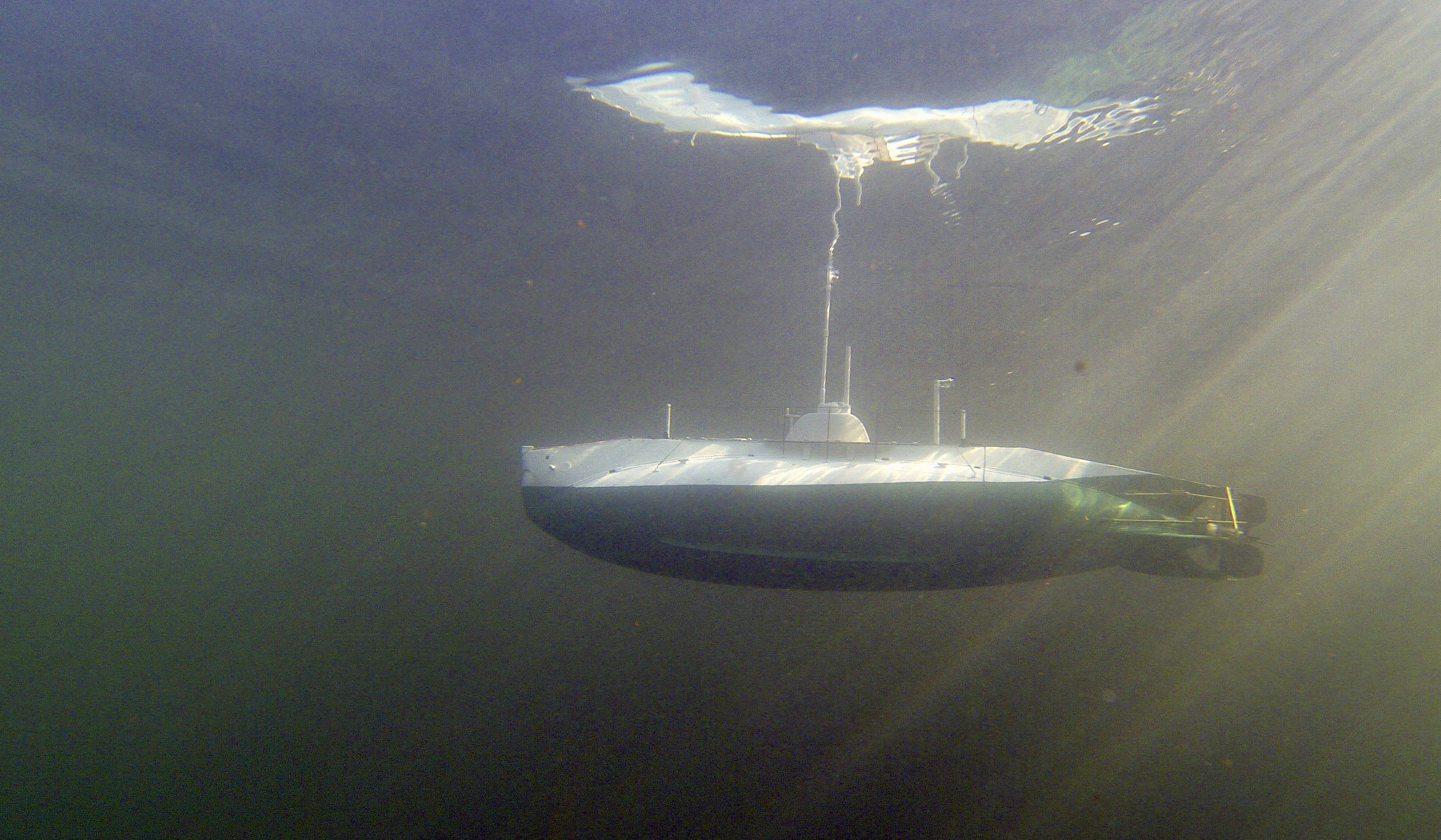
FullSizeRender.MOV Finally the chance for some serious testing, spent a few hours in a pool in Lichtenstein. Found a quiet spot to practice dives….. I think I need to move about 10 gram ballast from aft to bow (Kind off one passenger walking inside..). More testing tomorrow, followed by a 10 hour drive home…. IMG_0571.MOV FullSizeRender.MOV
- 55 replies
-
- 4
-

-
-
- auguste piccard
- submarine
- (and 2 more)
-
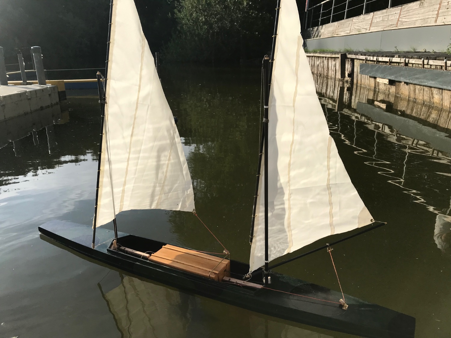
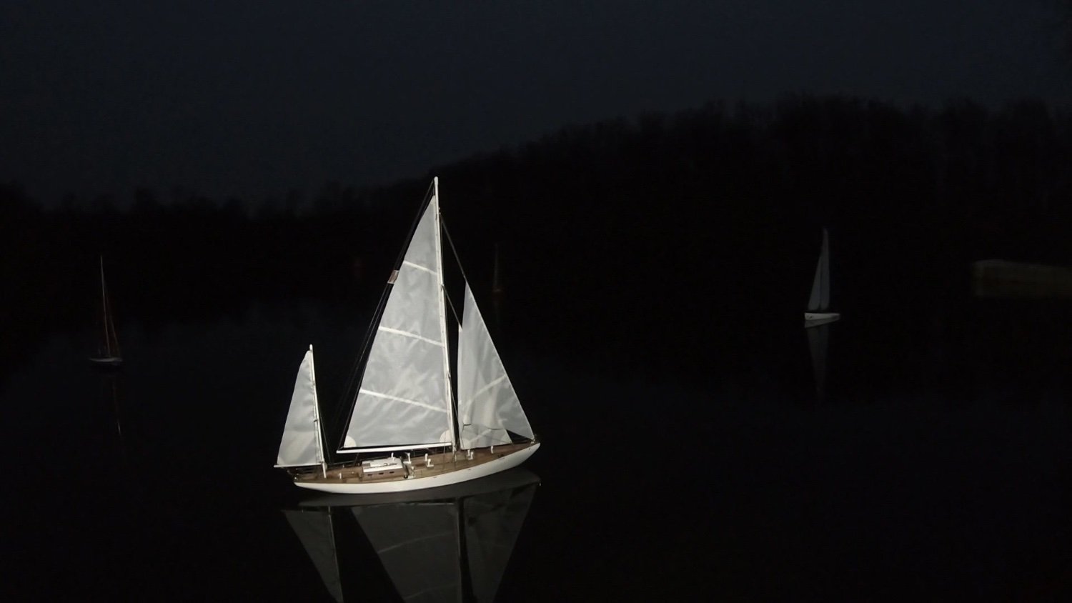
Today there was some wind at my model sailing club in Netherlands. Not very much and the trees make voor quite variable wind, but I managed to get half an hour of relaxed sailing, learning how the boat reacts. Happy with the result!
-
Ok the boat did get wet today and I got a few pictures! I had a 1.2 kg lead bulb as „fake keel“ in addition to the daggerboard and rudder. Total weight was 2,5 kg and it seemed to give reasonable stability. The technical installations (two small winches, a rudder servo, battery and receiver) were inside a “fake ammunition chest” in the centre of the boat. A small amount of water came into the boat but nothing to worry about. However the sheets got hung up the first time the winches pulled them in and pulled the tensioning springs of the sheets apart. Learned something - and apart from a pair of springs no damage done. But as a result I could not let the boat go - just had it drift around in the harbour where still the wind would occasionally move it nicely. Look forward to the next attempt. Might reduce keel ballast weight a bit.
-
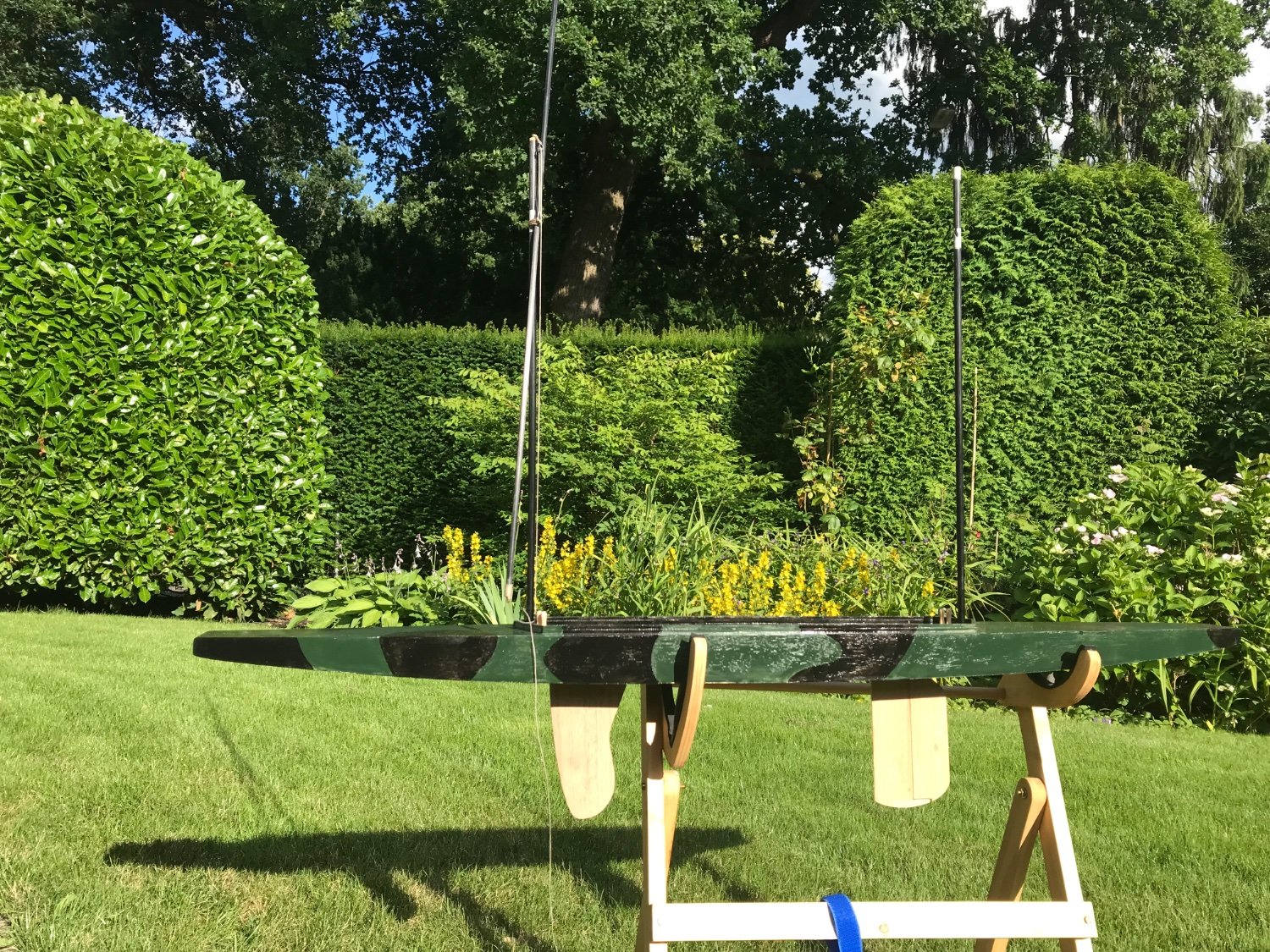
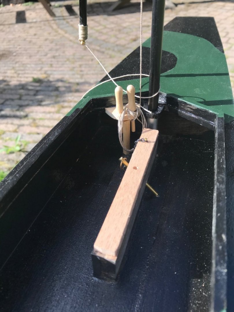
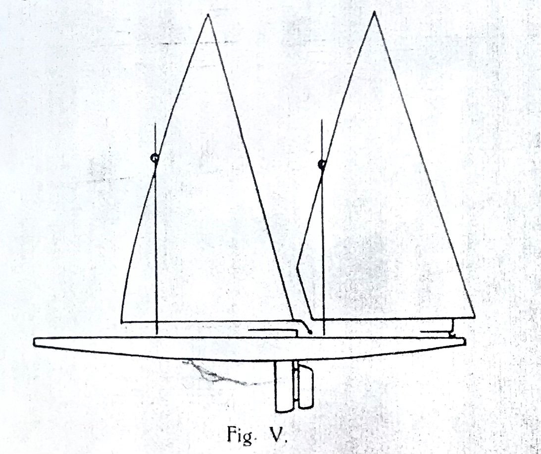
Here is an aerial photo of the fort - part of the “stelling Amsterdam” (now a Unesco world heritage site). That would be the canal/river that my grandfather would have sailed on. Good place for wind - no currents, might get choppy but no long swells. The hull is complete and painted in the main colours the army would have available in 1914 (green and black). I cannot discern any standing rigging on the one picture I have, and for ease of taking the masts and sails off for transport I decided to forego it. The Carbon masts are stiff enough without it. One mast has a cross brace for a Latin sail, the other will get one plus a boom for another Latin sail. belaying pins hold the running rigging, which secures the mast while sailing, and the three “daggerboards” built can be secured in their housings with messing pins. winches, rudderservo, receiver and sail material have arrived for the next steps.

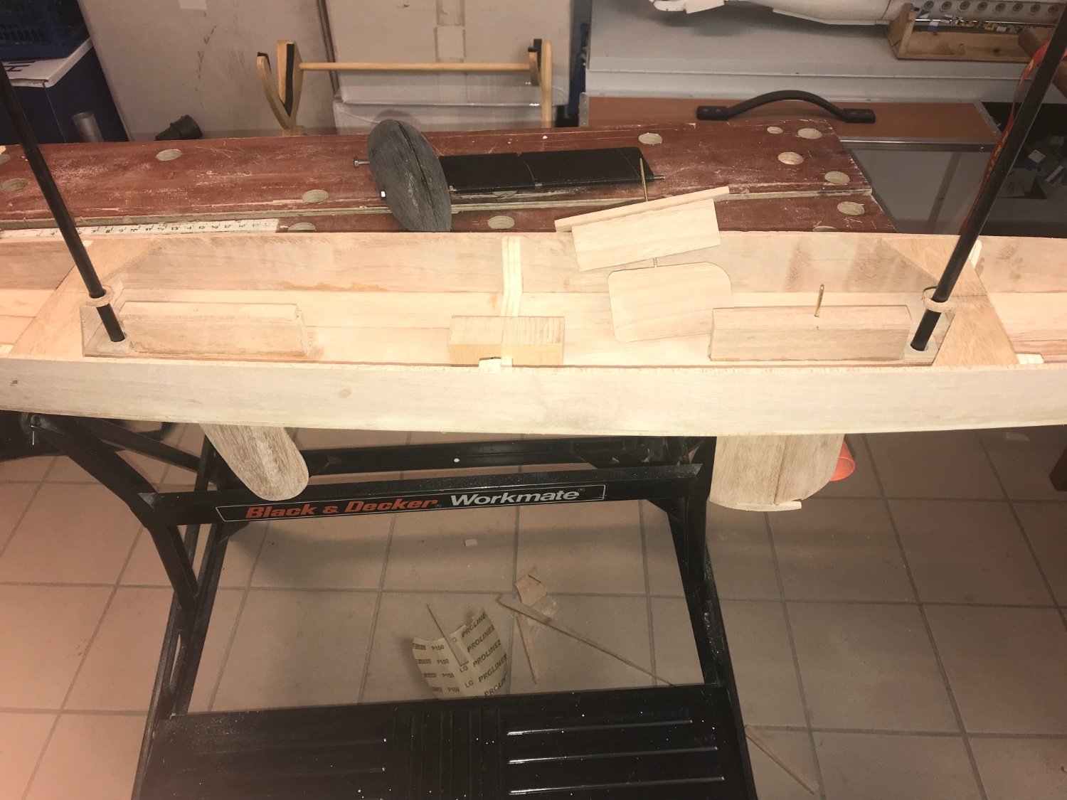
-
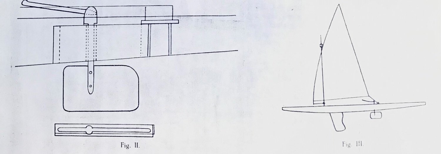
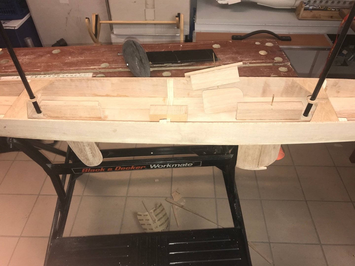
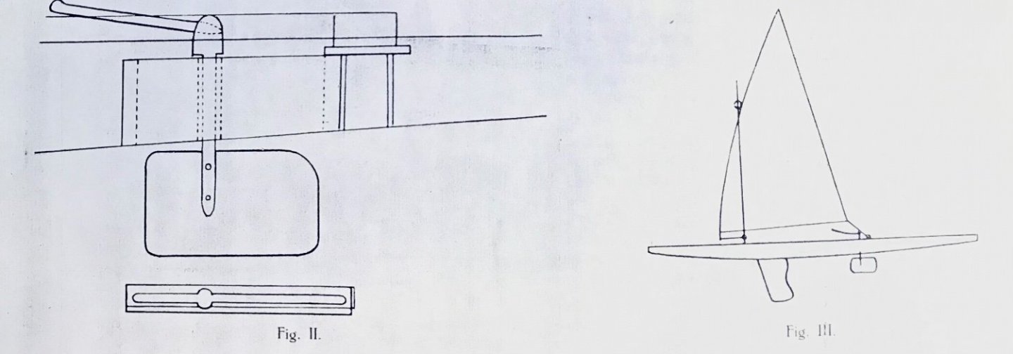
With the hull made, I made two “sword holders” and the three “daggerswords” that my grandfather experimented with, one just a rudder, one just a sword and one a sword with rudder. The hull has got bulkheads fore and aft onto which the mast holders will be mounted. All reasonably easy work - drawing directly on the hardwood and using a manual jigsaw mostly. In the centre of the hull is a small piece of hardwood onto which the lead bulb-keel will be mounted when I test her out. next steps will be basic painting in WW1 Dutch army paint (basically wherever they could lay their hands on) and then I can stark working on the deck. from the description and sketches I cannot determine if the boat had any standing rigging at all - need to try that out!

-
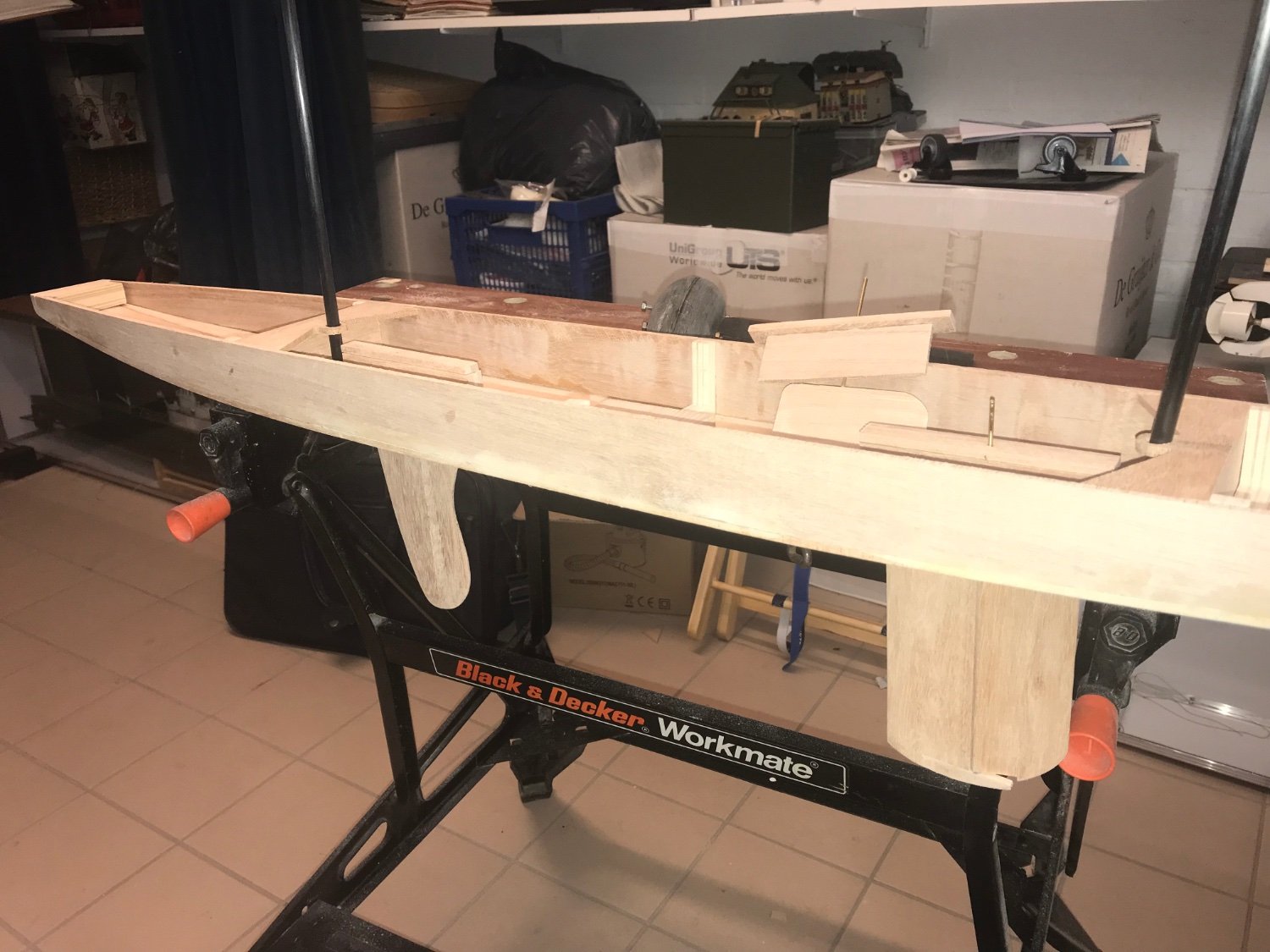
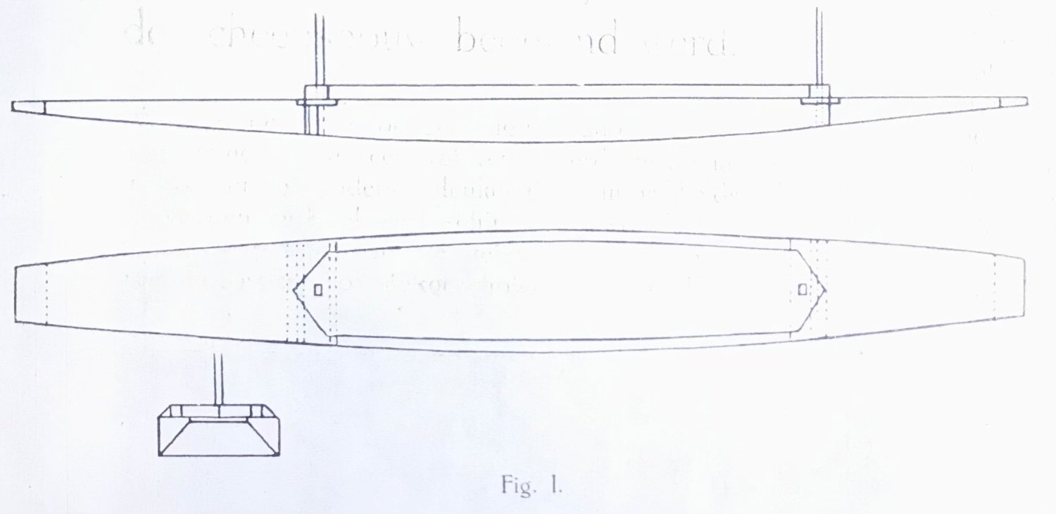
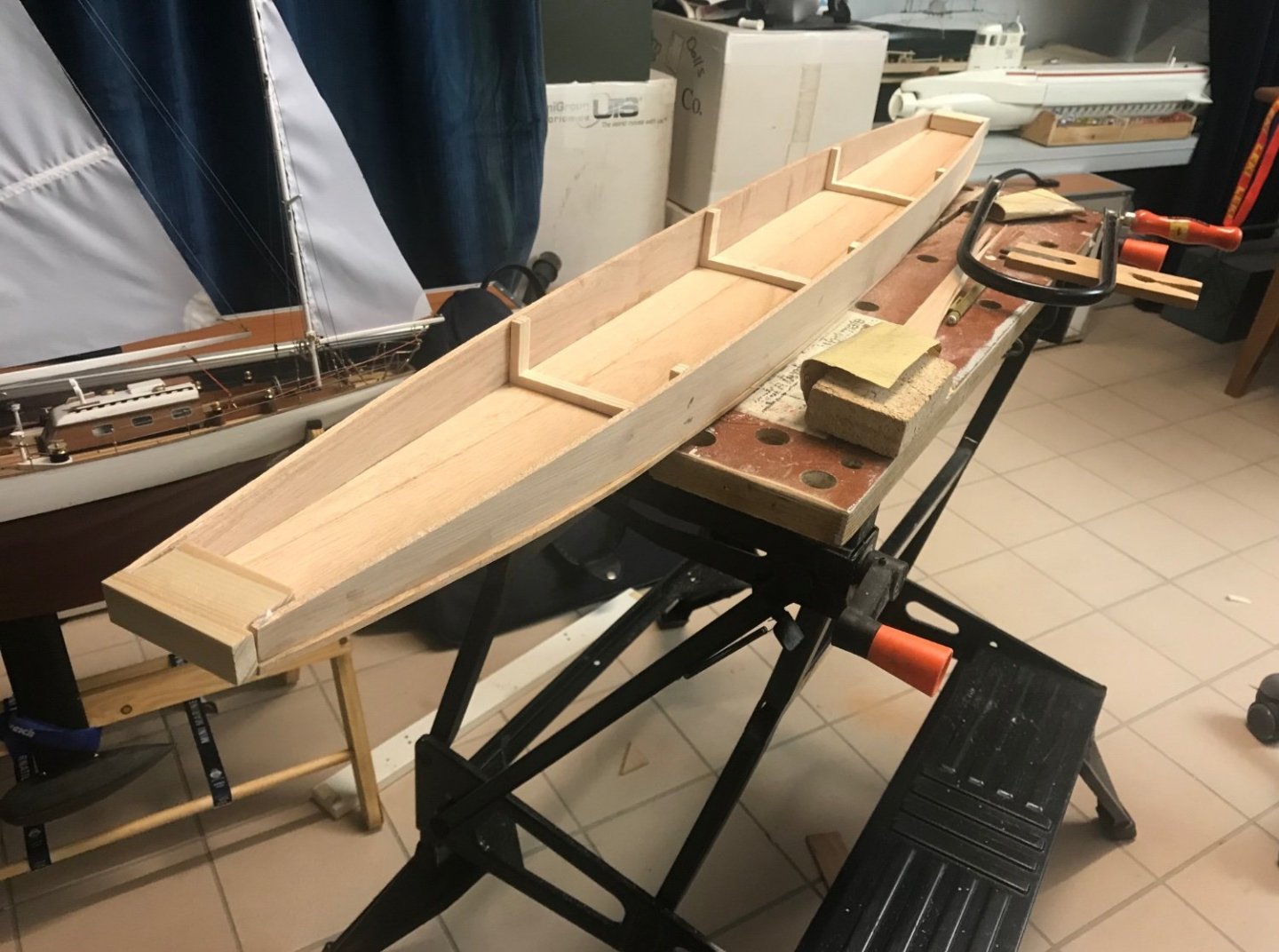
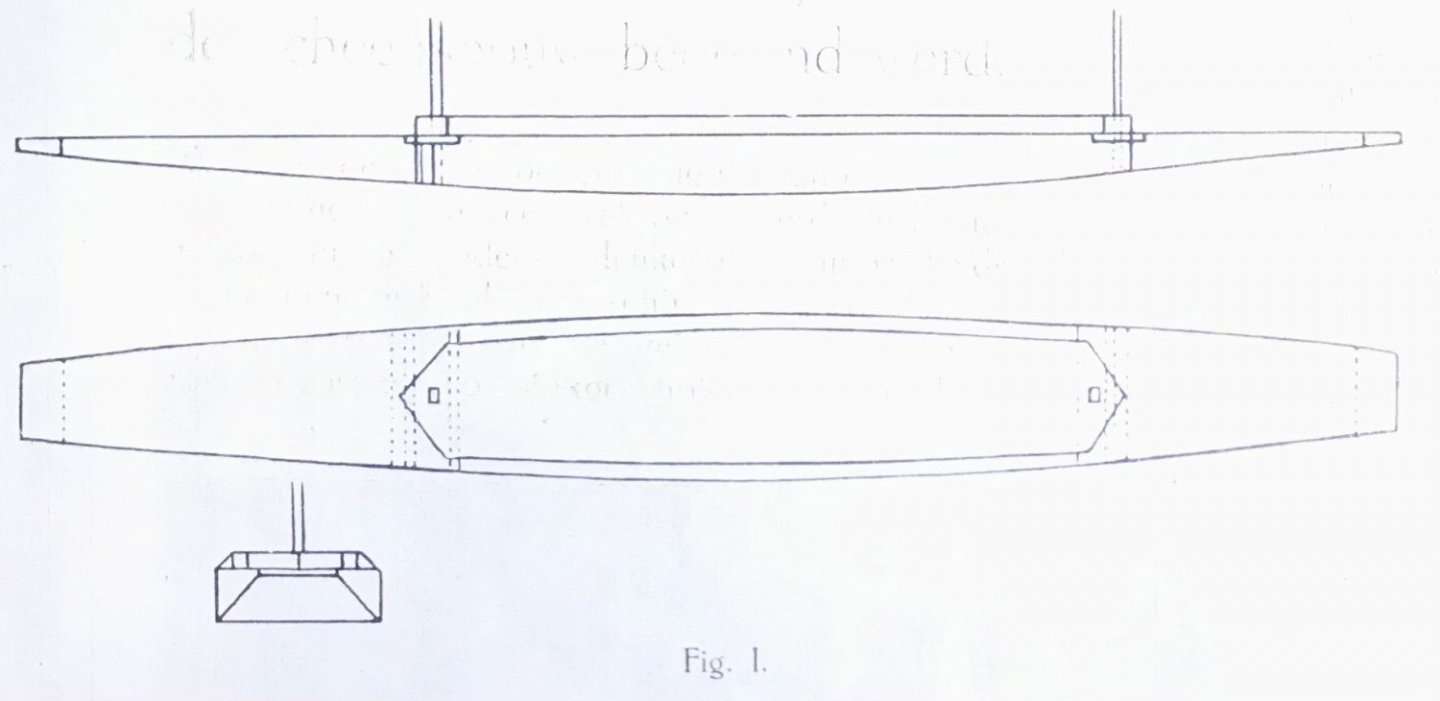
Started on the hull - as in the description these consist of three planks for a flat bottom and two sides perpendicular to that. Found some hardwood that fits that which drove the scale to 1:5,3 at 115cm overall length. next will be to prepare the hull for the masts, rudder, keels and a “false bulb keel” in case I need it. this is becoming a “why spoil it with a plan/drawing” type of build! regards Freek

-
Nice model - and very useful info for my just started build of my grandfathers “sail canoe/ferry” for which I only have a few images! Nice!
- 31 replies
-
- 3
-
-
- Sailing Canoe
- Finished
- (and 1 more)
-
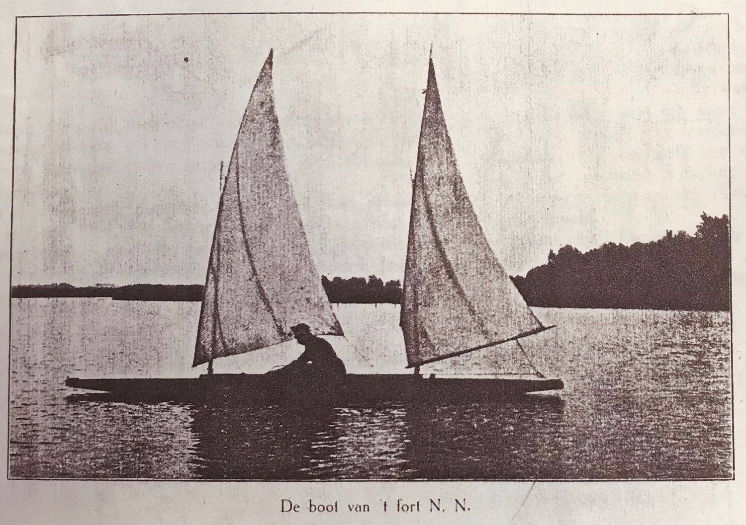
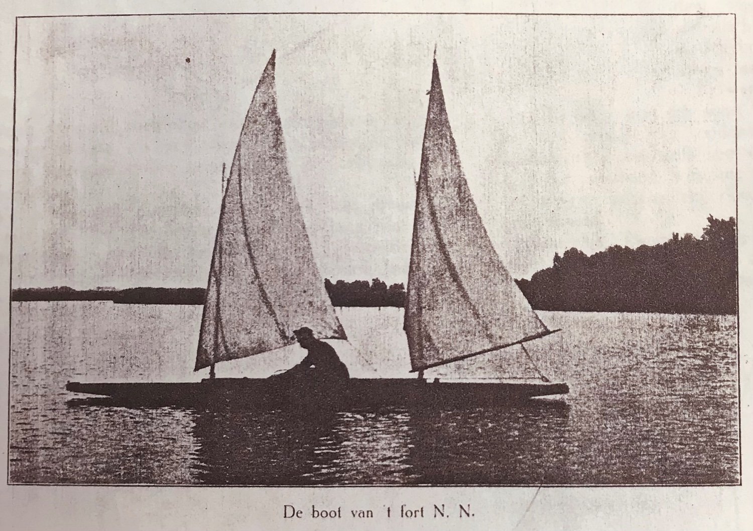
I intend to make a model of a 6 meter barge/sailboat that my grandfather designed and built when stationed during WW1 on a fortress of the Dutch “water defensive lines” around Amsterdam. As the Netherlands (thanks to this defensive line of fortresses) remained neutral in WW1, the troops stationed there had much time on their hands. My grandfather was studying shipbuilding at Delft engineering school when he was called up into the army. in attached article (which first appeared in 1914 in magazine “de watersport” which went out of business in 1937) he describes building a footferry that doubles as sailboat on the shallow canals and lakes surrounding the fort. the name of the fortress (and his own name) were withheld in the article! I would like to build a radio controlled model of this “boat” if I can. At first glance, at 6meter long, 0,7meter long, and 0,25meter high (freeboard plus draft), the boat could be quite unstable. Masts are not that high (3 meter), and sails not that big, but it’s nearly a canoe! At 1:5 scale it would be easy to transport (150 cm long), but still very narrow (14cm) and shallow (5cm). I’m estimating the allowed weight including ballast at 1:5 to be about 2 kg. Given the design, I don’t thing a deep “central false keel” with lead bulb (as I did on Corsaro 2) would work on this boat and I need to put most of that weight into the sword and rudder. Any thoughts on scale, stability, tricks and tips are very much appreciated before I get going!! Hope the attachment is readable, here are some of the images Sailboat - Ferry WW1 -english.docx
-
Now, where was I? oh yes, sail making. the mainsail came out reasonably well for a first time user of the showing machine (might be too much tension on the thread in the sowing machine). Played around with a fan in my workshop to set the sheet lengths and servo settings on the transmitter. Then brought it to my model sailing club for a first spin - at sunset and in near windless conditions. When she did catch a breeze she moved quickly and heeled a bit. Next attempt was in a quiet arm of a local river in similar light conditions. Pics taken from a movie so resolution is not well. As usual need to do some repairs but I’m reasonably happy. Cleaning the hull is also needed! I think I’m going to consider Corsaro-2 finished - apart from testing with more wind and the consequences that may have. I deepen the bulb for stability for example.