


EricWiberg
-
Posts
224 -
Joined
-
Last visited
Content Type
Profiles
Forums
Gallery
Events
Everything posted by EricWiberg
-
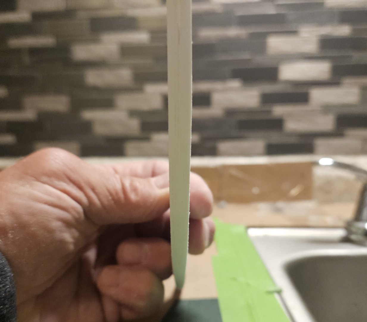
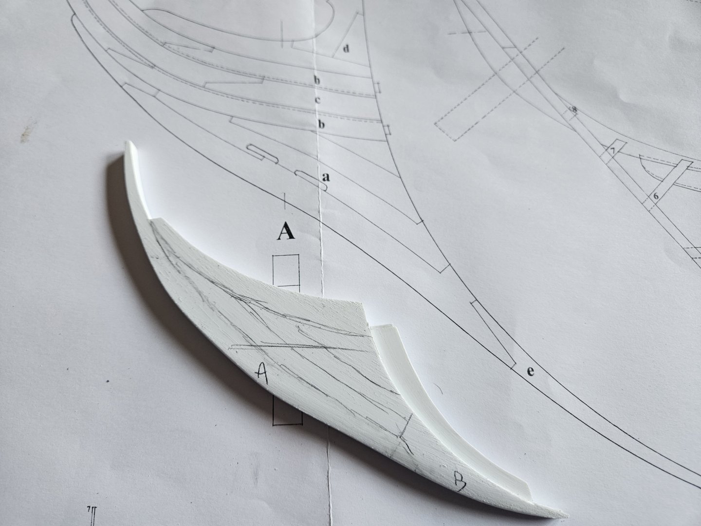
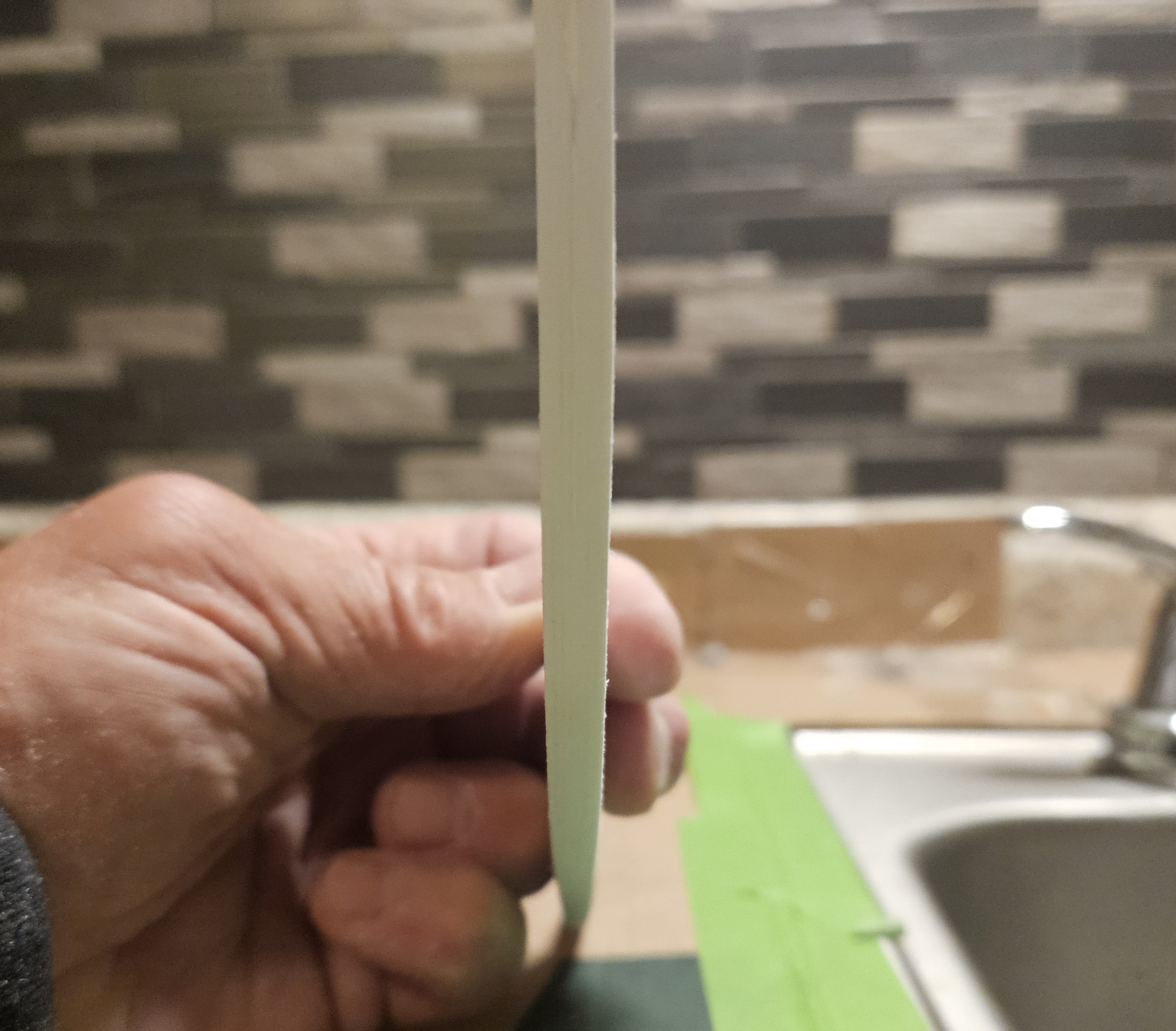
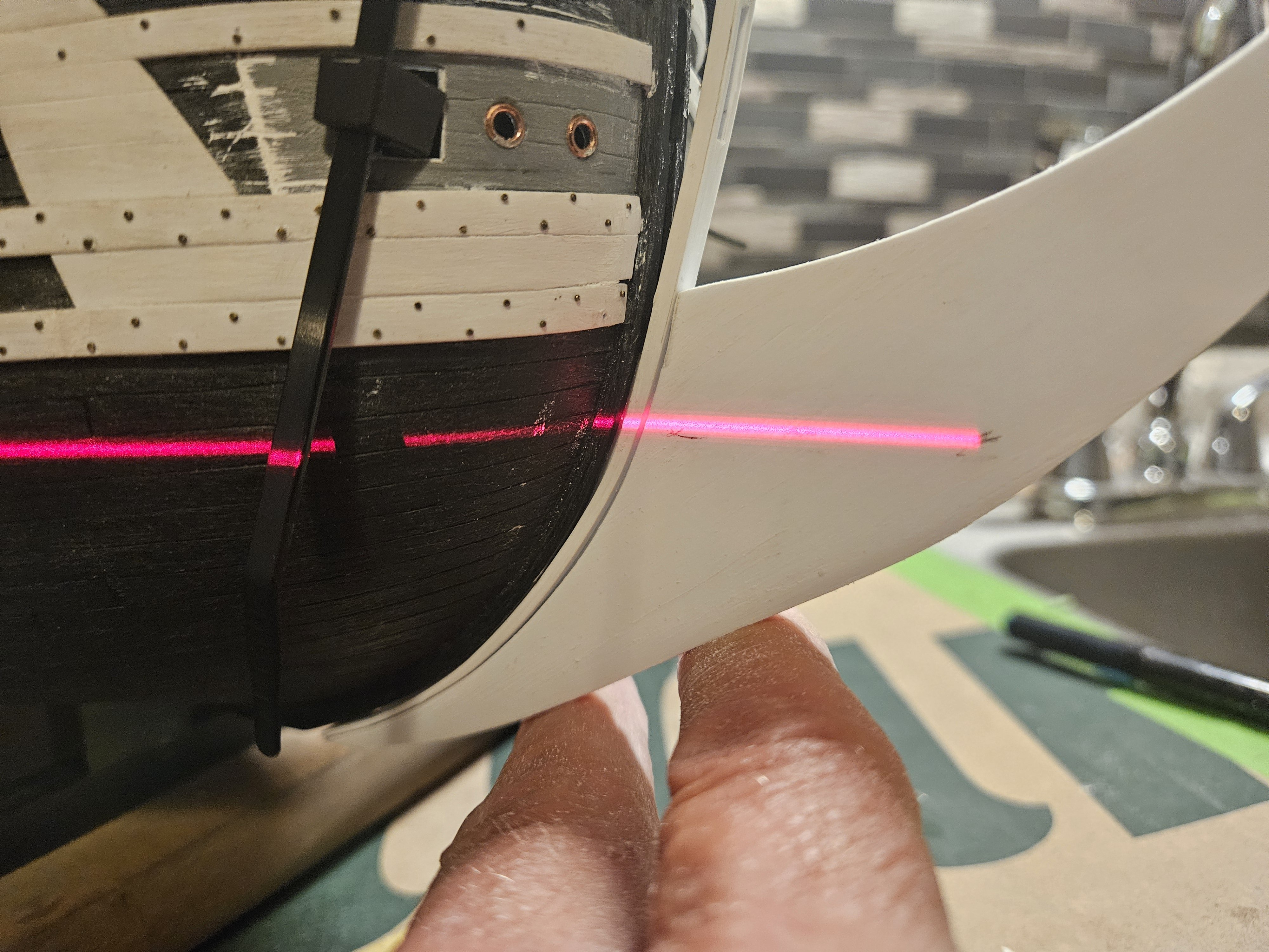
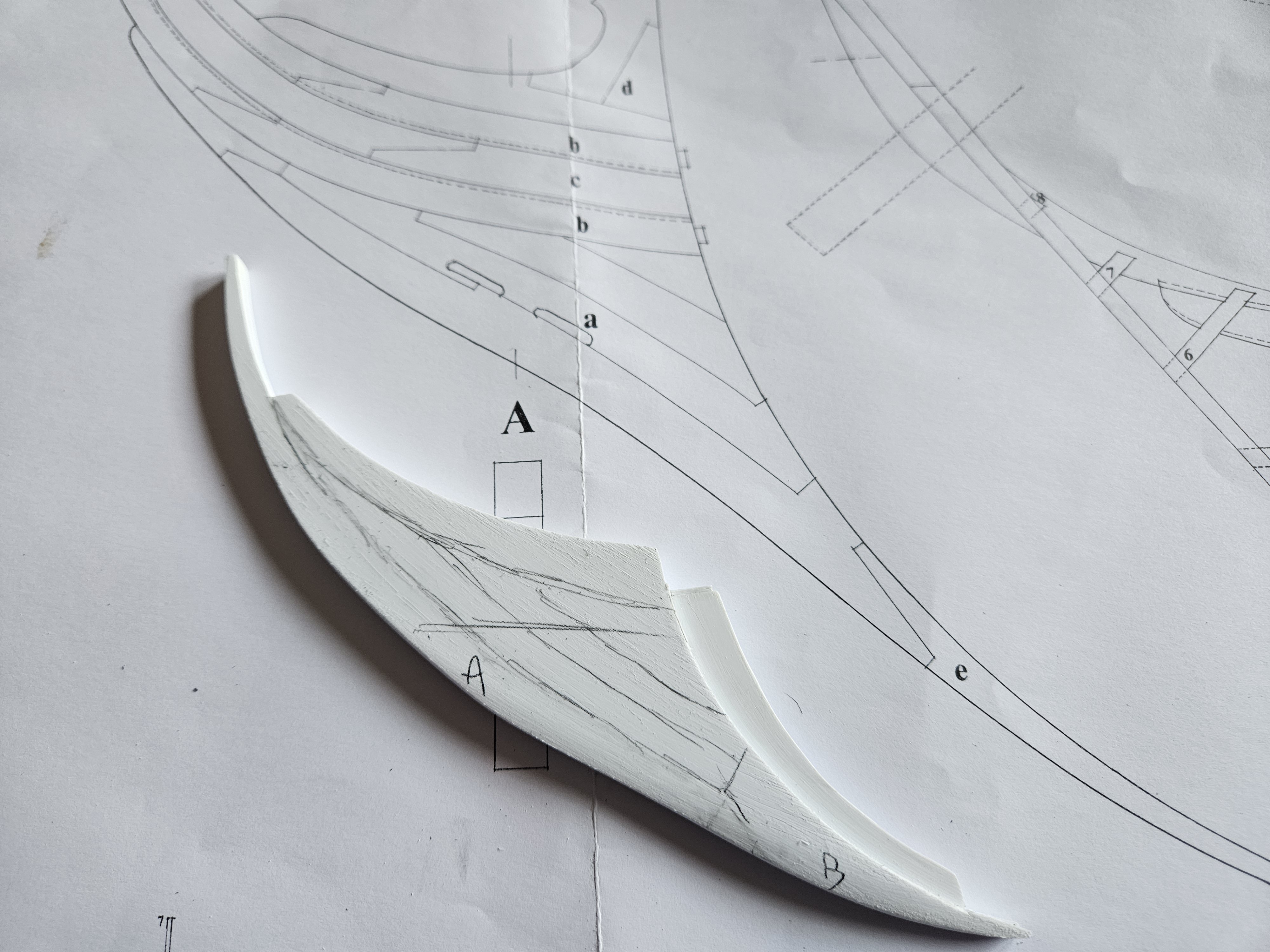
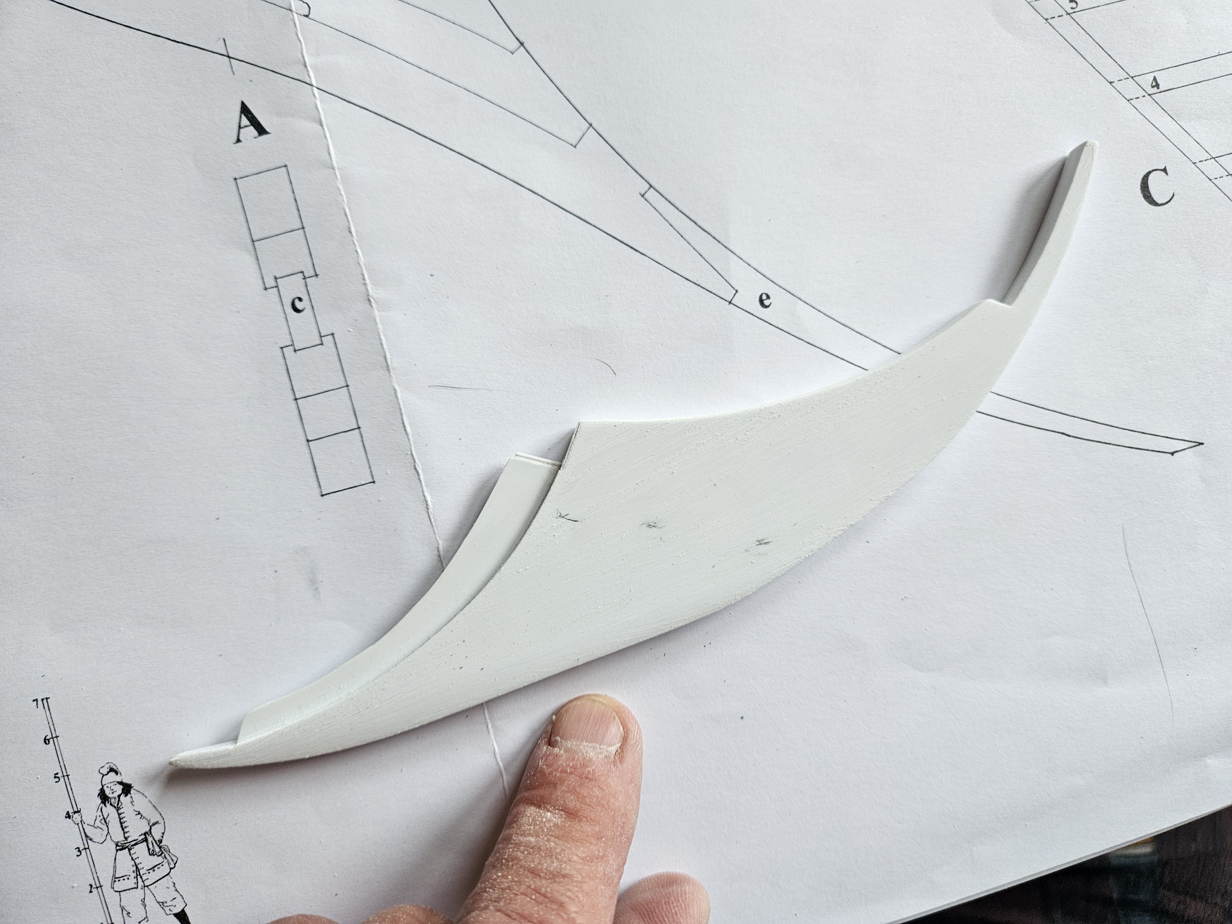
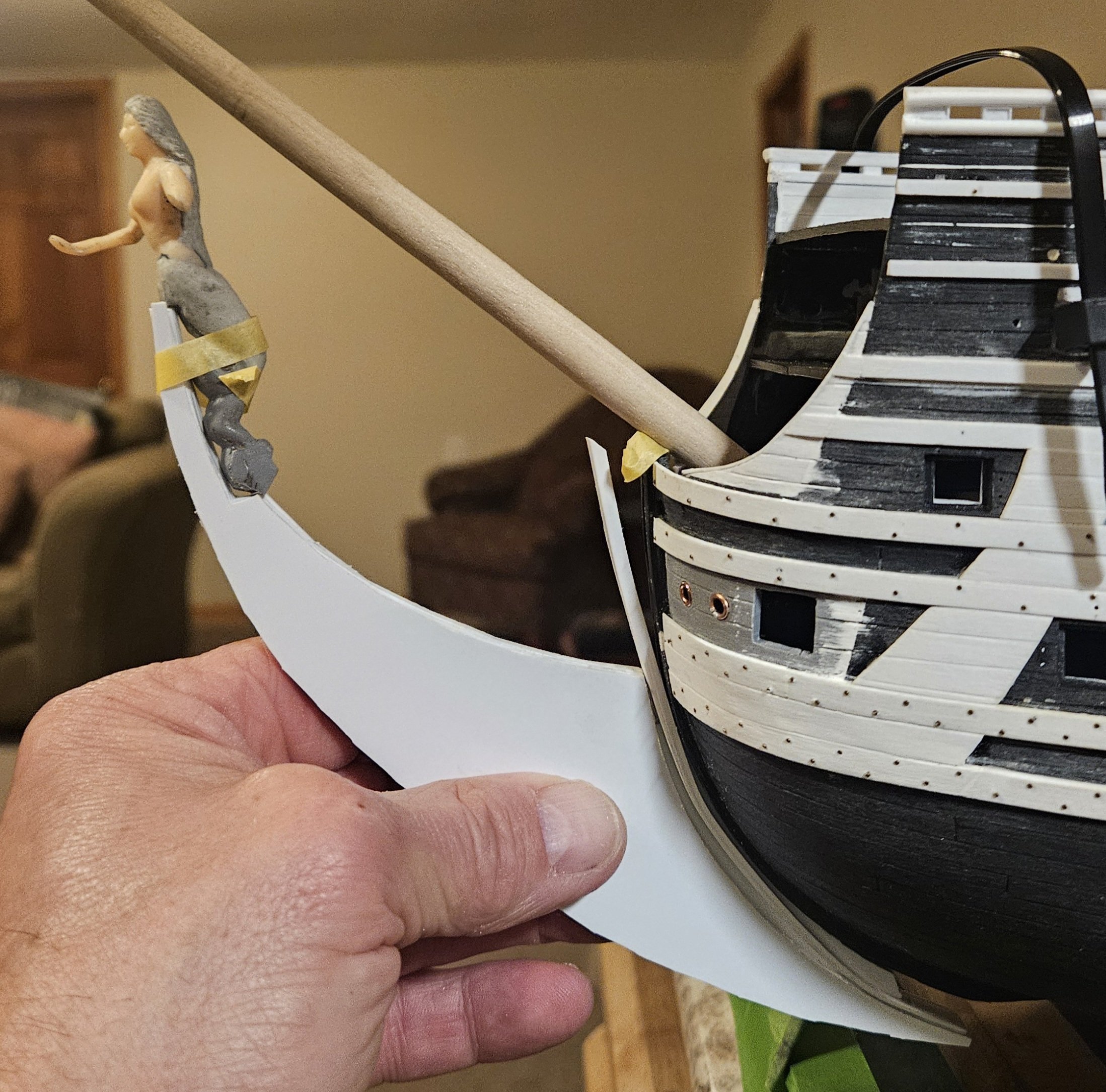
I carved out some early morning time today, and the goal was to start tapering the cutwater appearance for the knee of the head. First, I wanted to subtly change the shape of the knee of the head so that it is not one long curve from base to the figurehead, so where my finger is pointed, there is a now a slight indent. Next, I established the waterline, as my operating assumption is that from the waterline up to to base of the figurehead, there is little to no taper. Nexy, I sketched in some very rough guidelines to indicate how all of the pieces of the knee of the head were attached. Not the final lines, of course, but I will scribe in the final lines after the tapering process. I did this because my assumption is that only pieces "A" and "B" were tapered ("A" and "B" is penciled in on the piece) in other words, just the very leading edge of cutwater. Finally, this is a head on view. Believe it or not, the width at the top (i.e. above the waterline) is 6.25mm, and it gradually tapers down to 4.25mm at the base. Too me, there seems to be very little visible taper at this point, even though it is there. Again, my assumption that only "A" and "B" pieces will be tapered might be wrong, but I can't believe that all of the individual pieces that make up the knee of the head would all be tapered in unison, starting at the stem and marching forward to the cutwater, at least below the waterline. It is not razor blade sharp as in the clipper photo that I posted just abve this, but it does seem to be more in line with the Zeven Provincean photo that Marc also posted just above.


- 432 replies
-
- 5
-

-
- soleil royal
- Heller
- (and 1 more)
-
Marc, that second photo is very helpful and really shows the taper
- 432 replies
-
- 1
-
-
- soleil royal
- Heller
- (and 1 more)
-
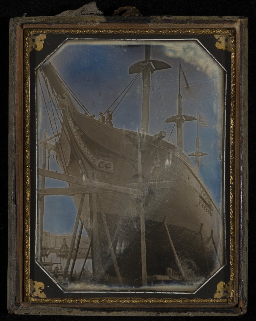
I found this example of a tapered cutwater on another blog of Model Ship World... granted, it is a clipper ship some 150 years AFTER Soleil Royal, but it really shows the taper of the cuwater as it descends downward...
- 432 replies
-
- 1
-
-
- soleil royal
- Heller
- (and 1 more)
-
That makes sense, Marc. How far back from the leading edge did you start the taper? It looks like your taper goes from full width at the figurehead to... perhaps 2/3s of full width at the foot?
-
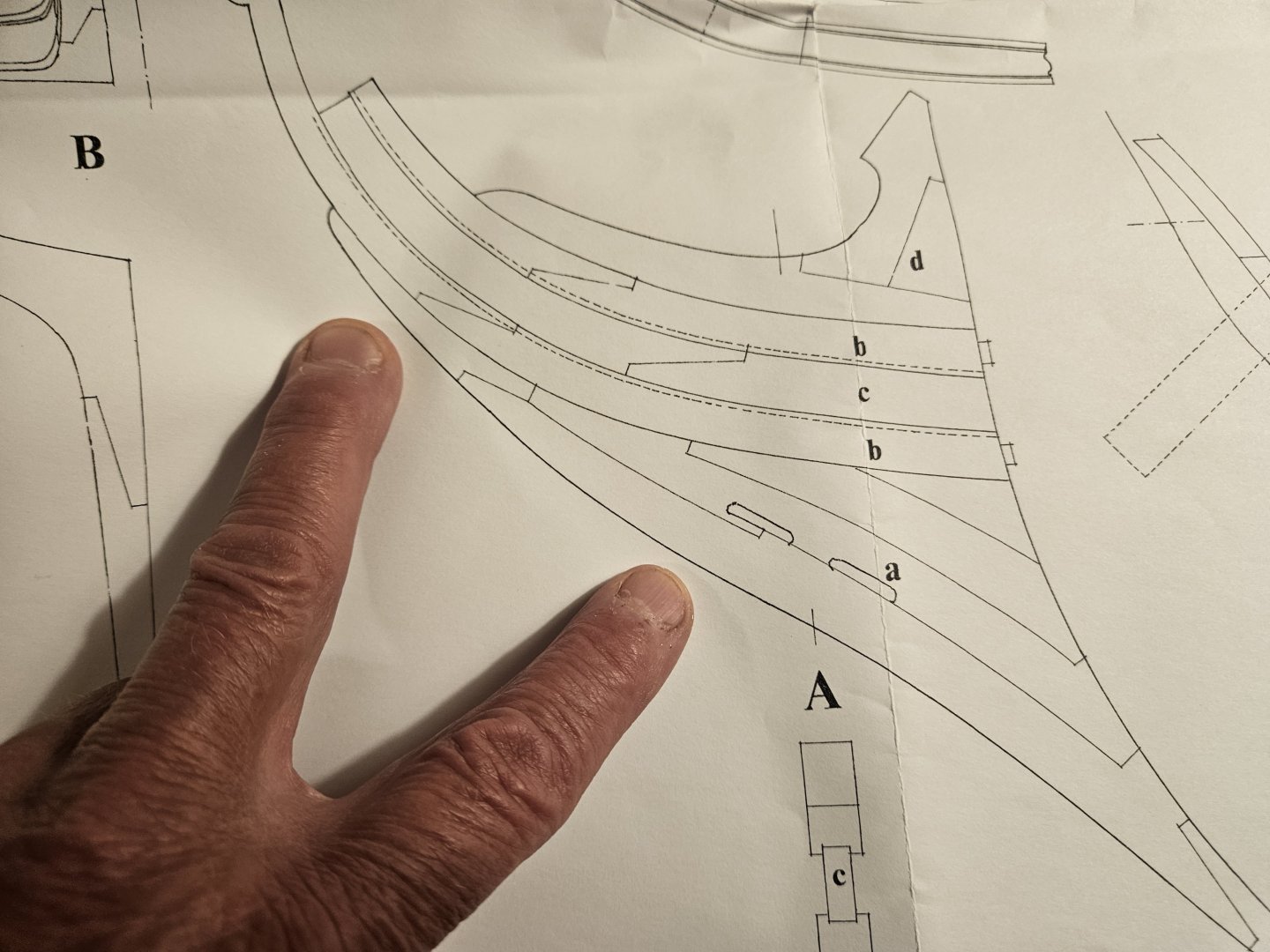
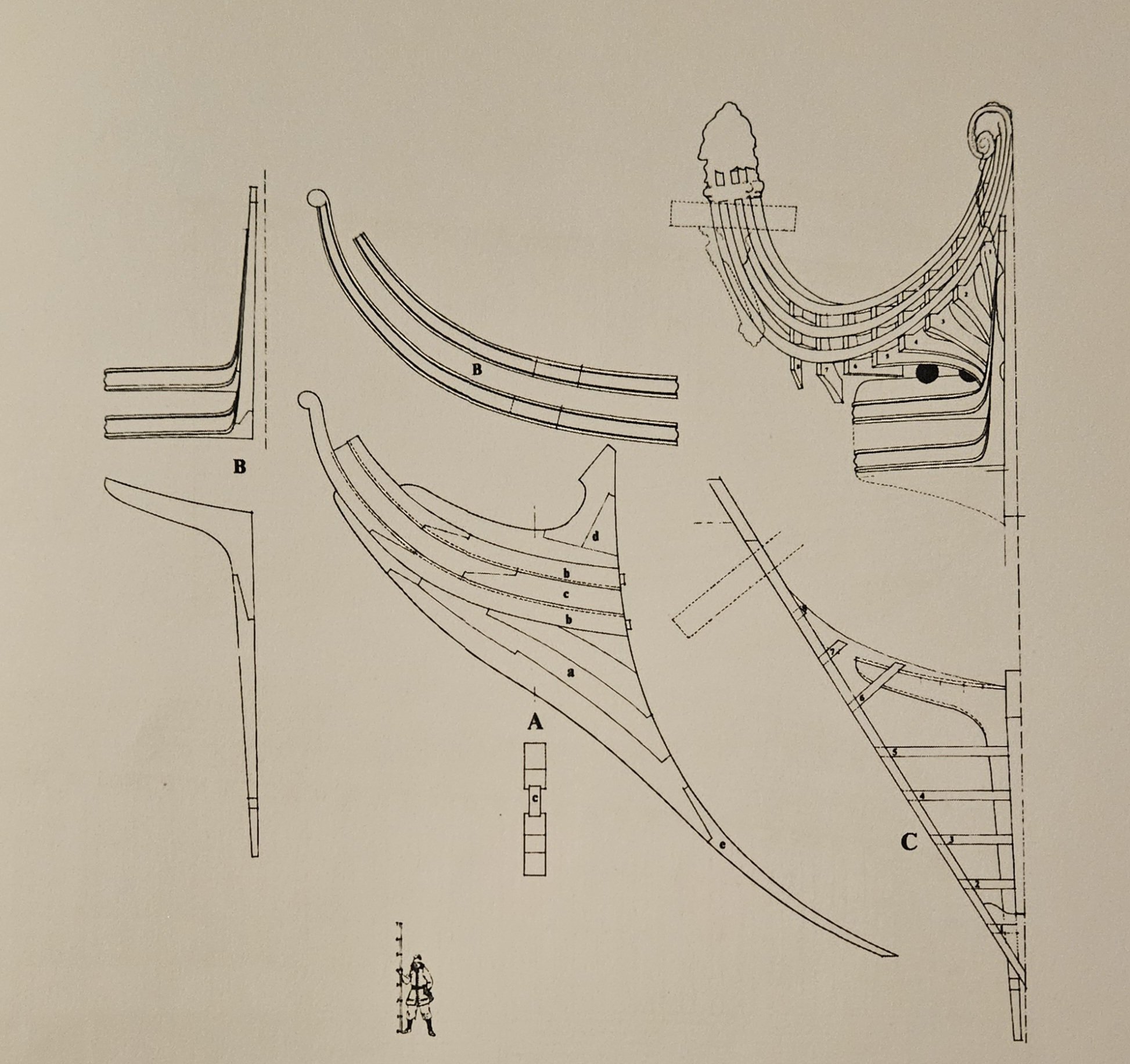
I have a question to the void... and it has to do with the taper of the cutwater. I know that the cutwater is tapered, thinner at the leading edge that "cuts through the water", as Marc LaGuardia noted in his post #1307. I think I have seen other references in blogs/books, but I am drawing a blank after 6 weeks away! As I hold the knee of the head, the thickness is 6.5mm, whch matches the kit dimensions. What I can't figure out is exactly what piece(s) gets tapered... here is the St Phillipe monograph, and the knee of the head is built of many pieces fastened together (I plan to scribe these lines in). Mu assumption is that only the leading edge piece(s) underwater needs to be tapered. My index finger is pointing at piece "A"... my middle finger is pointing at a smaller unlabeled piece. and in the lower right of the picture is another much smaller piece that you can partially see. So... I assume that only these three leading edge pieces are tapered, say from 6.5mm thickness at the stem to 4.0mm foreward where it cuts through the ocean? (I don't recall seeing any (proportions or guidelines anywhwere). Now, the piece that my middle finger is pointing to is well above the waterline, but I assume that it is has to be tapered down back to front to match the much longer piece "A" underneath it. I saw a website on the USS Constitution project, and they rebuilt some of the knee of the head and they clearly state there is a taper. But no mention of the dimensions and I can't see the taper in the pix. Oh.. and thos was another book that I managed to read in the past 6 weeks.


- 432 replies
-
- 1
-
-
- soleil royal
- Heller
- (and 1 more)
-
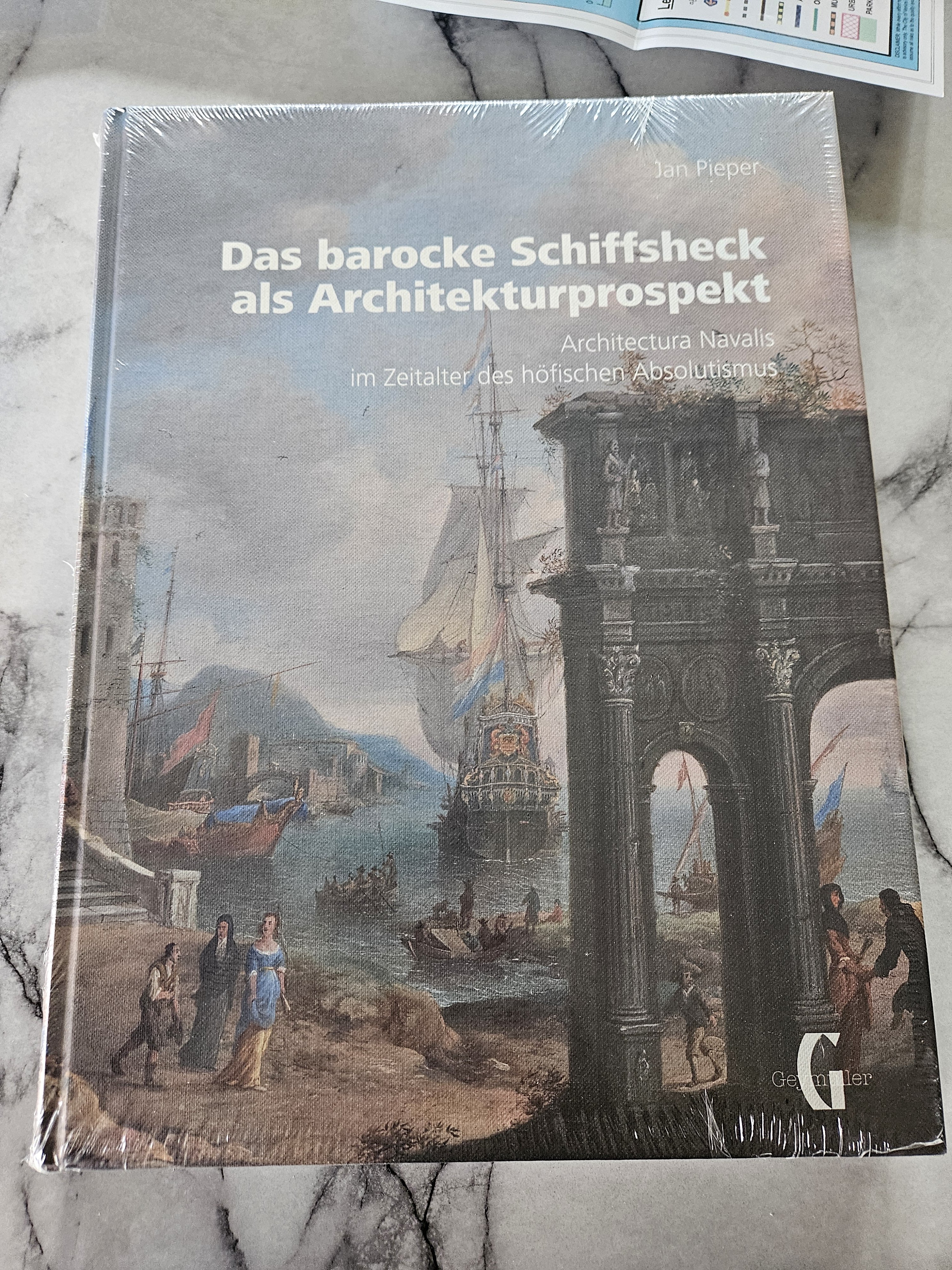
Well, it has been a long six weeks away from the shipyard... at least I had a lot of time to dig into the "Das barocke Schiffsheck......" a very interesting and informative book! I had to stare at the ship for a few minutes to remember what I had been about to do next.... ahh, the head rail development! But first, a little minor fitting work on the figurehead. I won't know for sure on the fitting of all of these scratch built pieces until they are glued in... but I think I can get 95% of the way there by constant fitting and checking. On to the head rails...
- 432 replies
-
- 3
-
-
- soleil royal
- Heller
- (and 1 more)
-
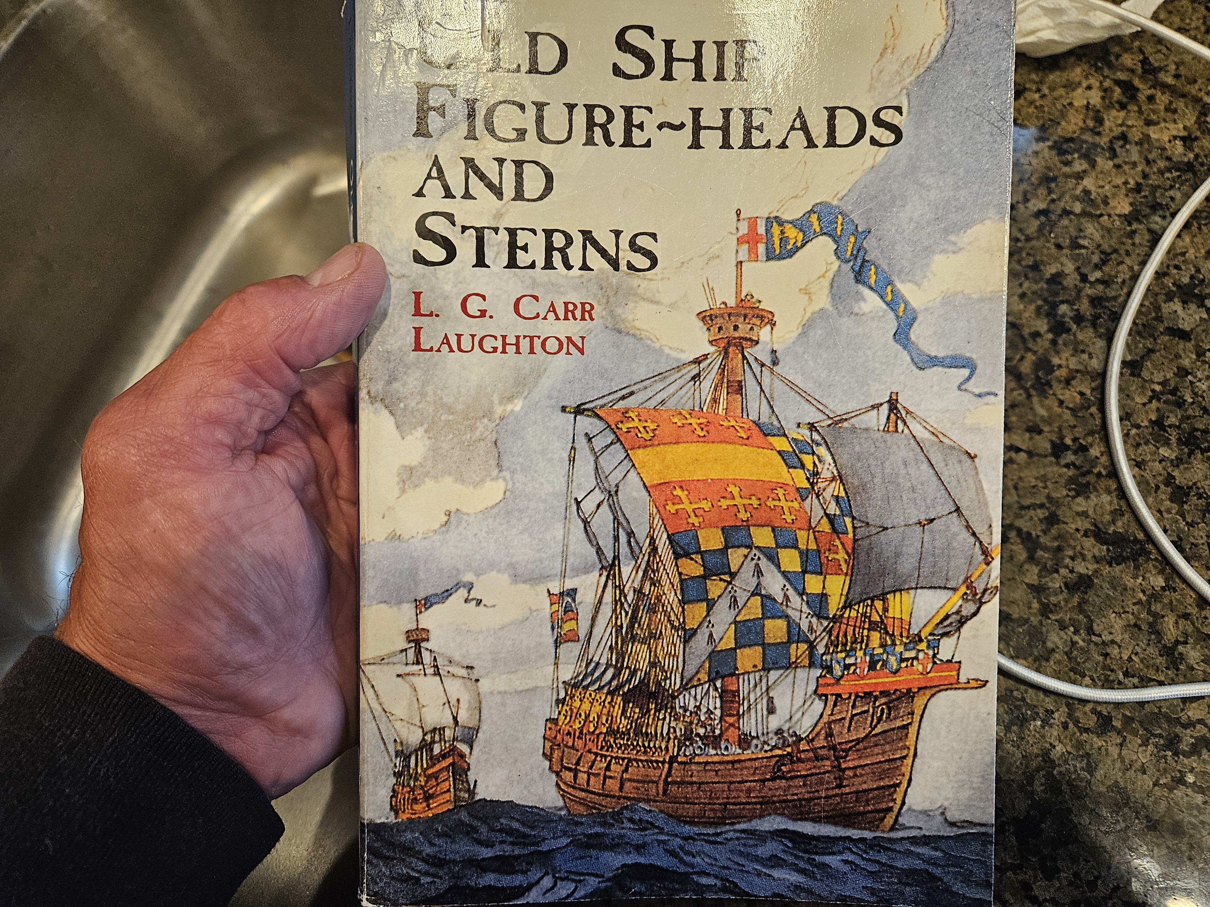
Very brief update... a 5 week hiatus away from ship building, much like last year at this time. However, like last year, I get to read books and review all kinds of SR blogs, which really helps me visualize. And.. this book arrived! As Marc has stated, it is really quite interesting and should prove a tremendous resource!

- 432 replies
-
- 1
-
-
- soleil royal
- Heller
- (and 1 more)
-
That makes a lot of sense, Marc... I will give it a try!
-
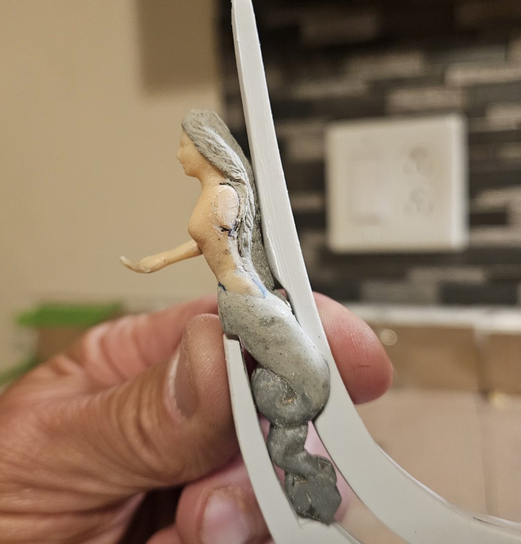
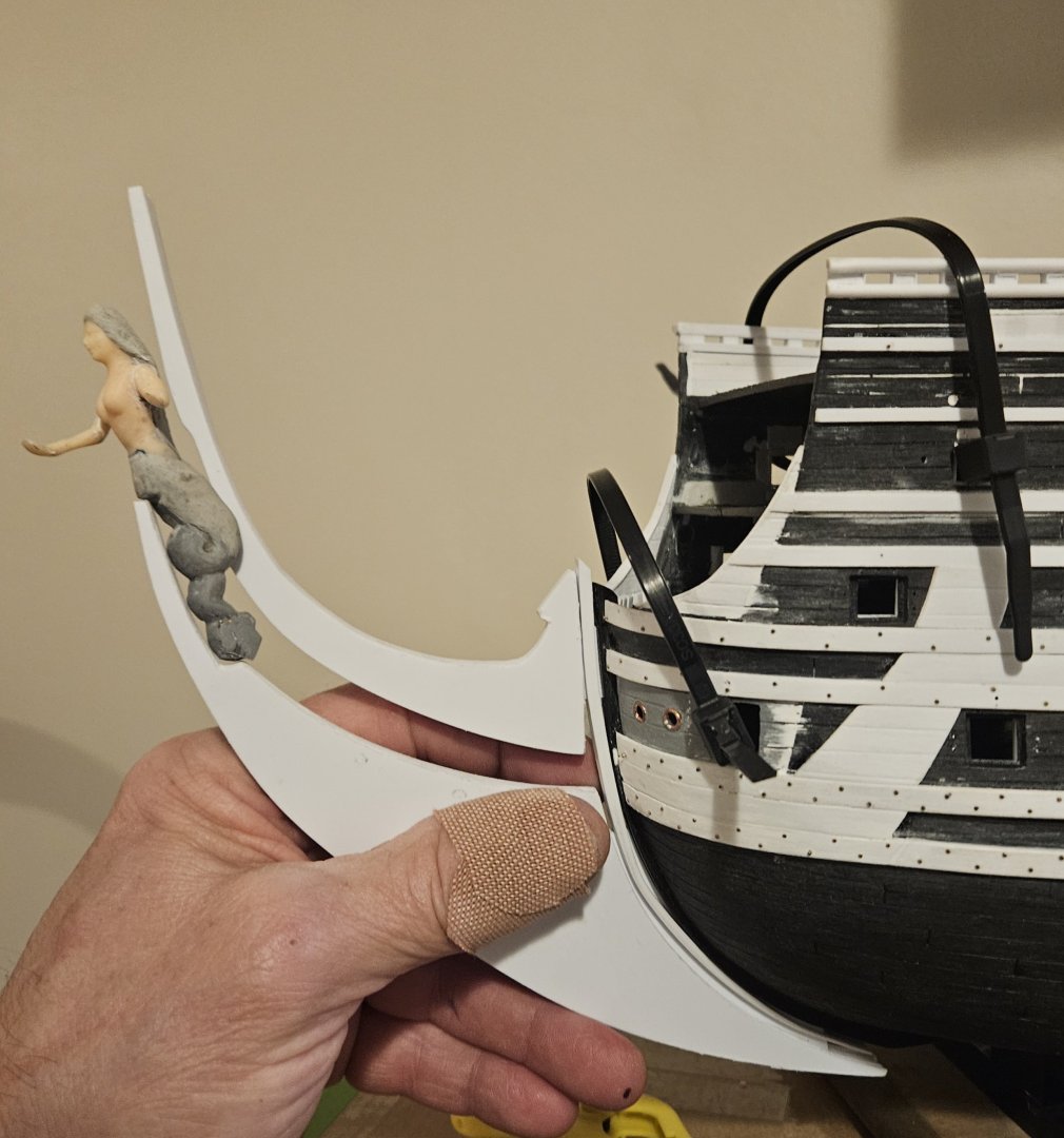
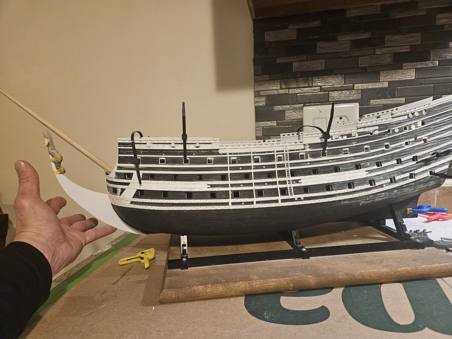
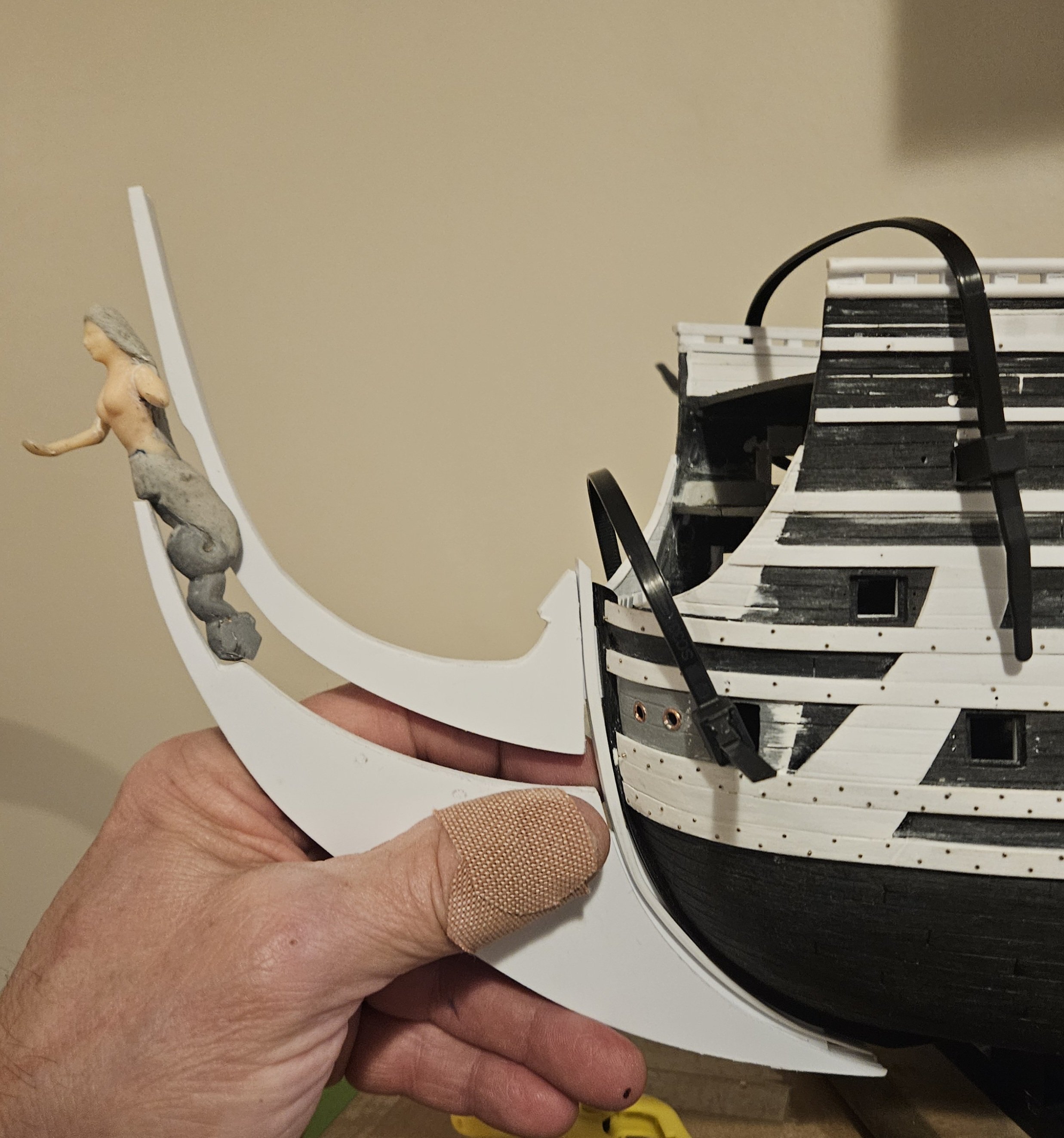
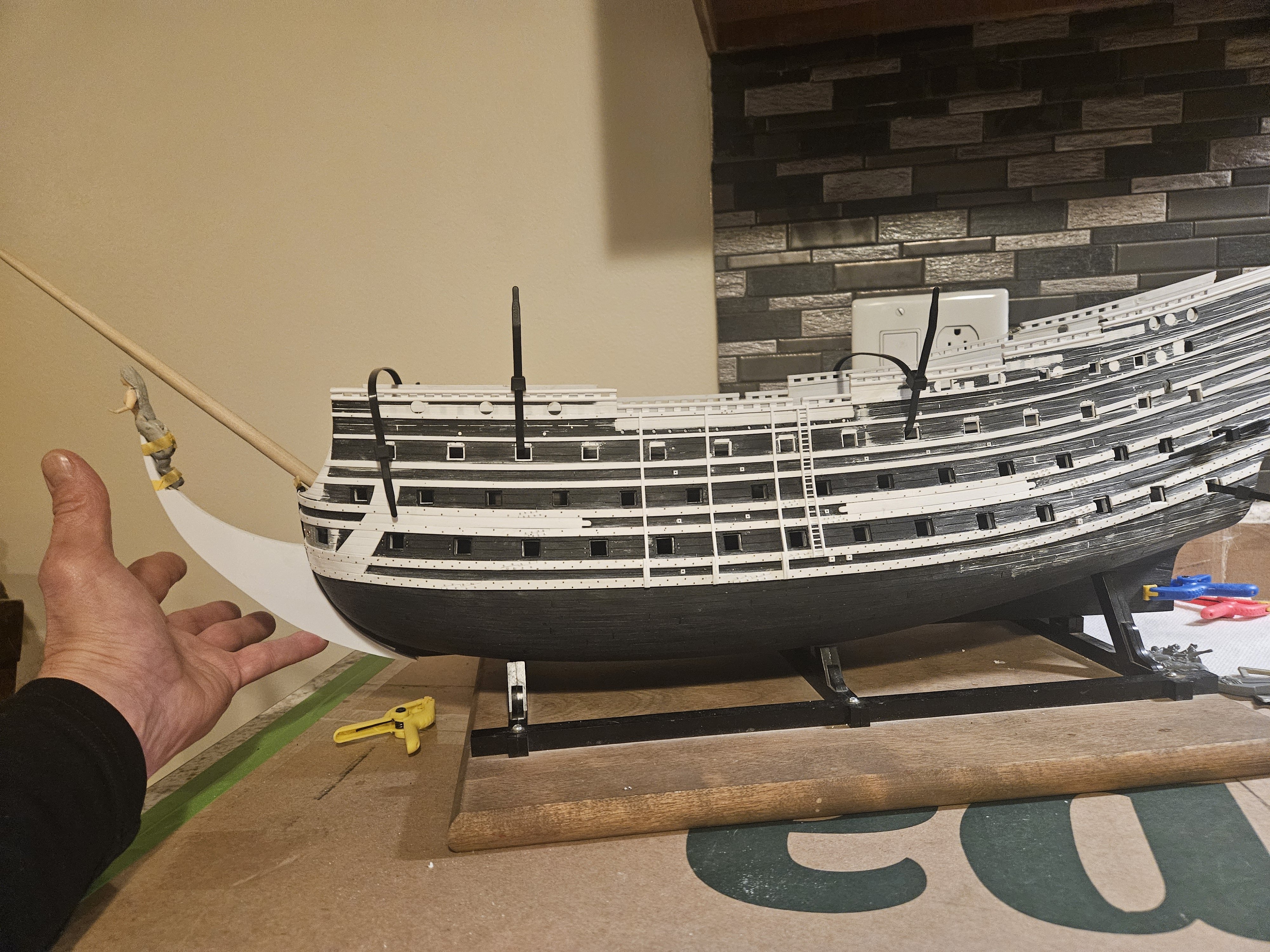
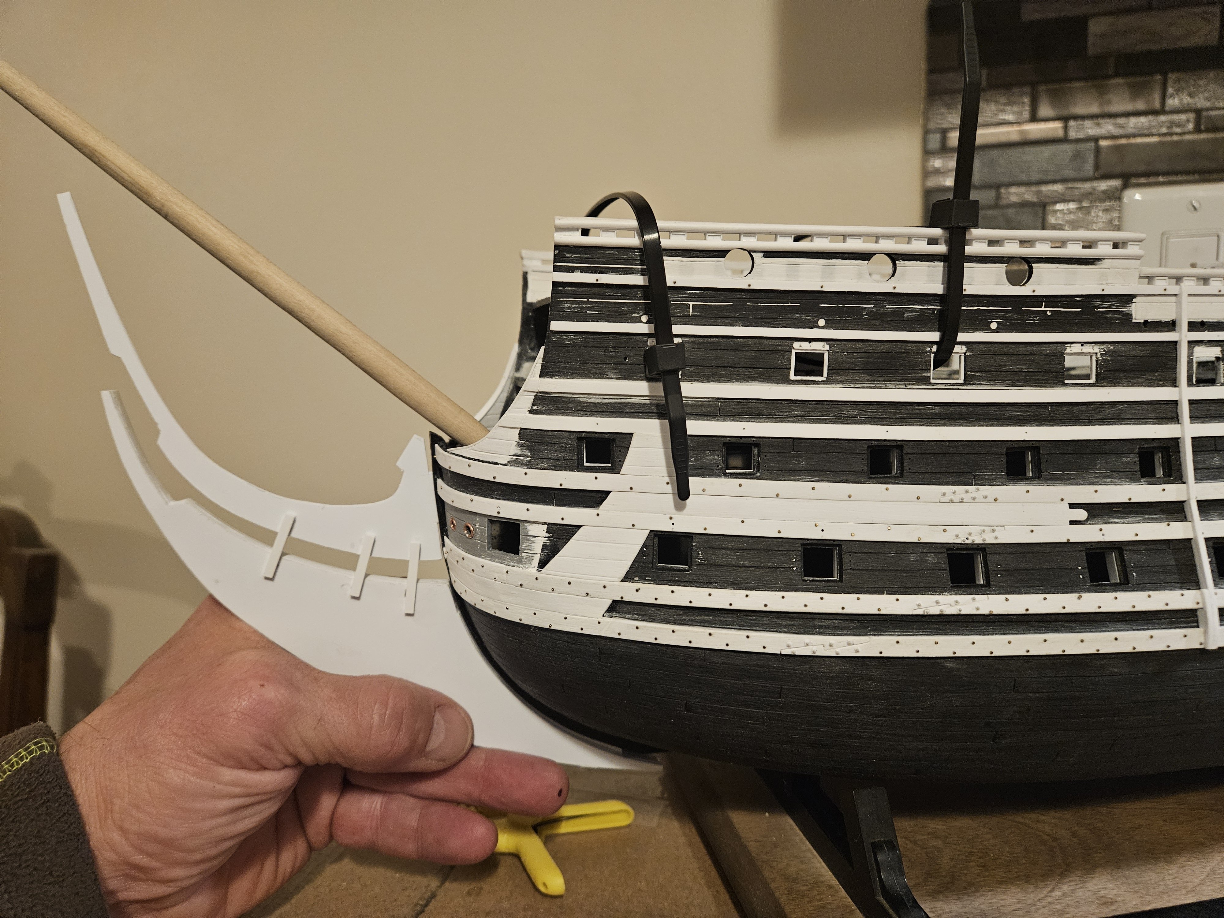
And that is it for the cutwater/head pieces for now. I cleaned up the upper knee; you will note that I left an extra long extension above the figurehead until the final assembly - better to be too long than too short! The first photo shows both pieces inserted into the stem "thickener" that my left thumb is on. Based on the St Phillipe monograph, the Heller kit stem is too thin. So to get approximately the same thickness as the SP monograph, I needed to add 1mm thickness at the keel, tapering up to 4mm extra in the upper knee area.... the figurehead is not in its final position, of course. The positioning in the photo below is not perfect, but I overlaid the Heller kit pieces on modifications to show that I was trying to get the head longer and lower... as Marc LaGuardia would say... that "Dutchy" look In my minds eye, this is the look that I was chasing after. Time will tell on how closely I was able to mimic that "Dutchy" look. One of the "Dutchy" characteristics seems to be that the rise of the cutwater is almost straight, at least until the gentle sweep up into the figurehead. I tried to add a bit of a curve on the cutwater, and also tried to bulk it up, anticipating that the extra mass up front would contribute to a longer and lower look. We will see when things start getting glued together! Finally, a crude aprroximation of what the head will look like... sans tie wraps!

- 432 replies
-
- 4
-
-
- soleil royal
- Heller
- (and 1 more)
-
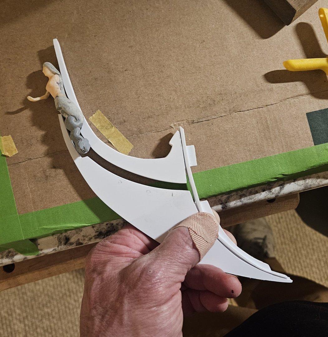
Well, I am close to a hard stop on the cutwater/head templates. The cutwater shape should be good to go. It doesn't make sense to fine tune it until the hull is glued together, as I have an aditional insert to thicken the stem. Those really need to be glued together tight and inserted into the hull before I can make any final modifications. I think that I have a final shape for the top knee. The convex curve on the underside of the top knee matches the concave curve on the cutwater. Finally, I made some spacer tabs that I temporarily glued to the cutwater/upper knee. These tabs maintain the precise spacing of 5.5mm that I have between the pair of bottom wales. I will have to do some precise carving to ensure a tight fit with the figurehead, but again... it doesn't make sense to do that until the hull and decks are actually glued together. You make note the inlet that I cut into the top knee where it will fit into the back of the figurehead. I have hemmed and hawed on this, but it seems to be the only way to have the top knee have a tight fit to the back of the figurehead AND also follow the general sweep upward of the cutwater to where it terminates at the figurehead.

- 432 replies
-
- 4
-
-
- soleil royal
- Heller
- (and 1 more)
-
The book has not!
-
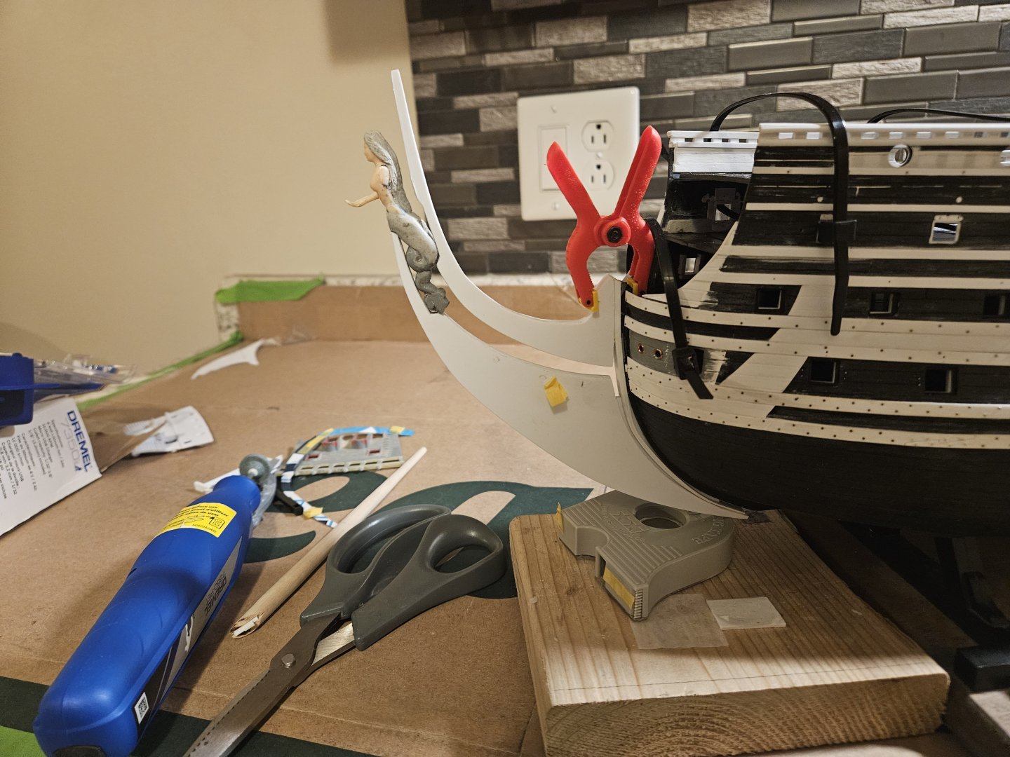
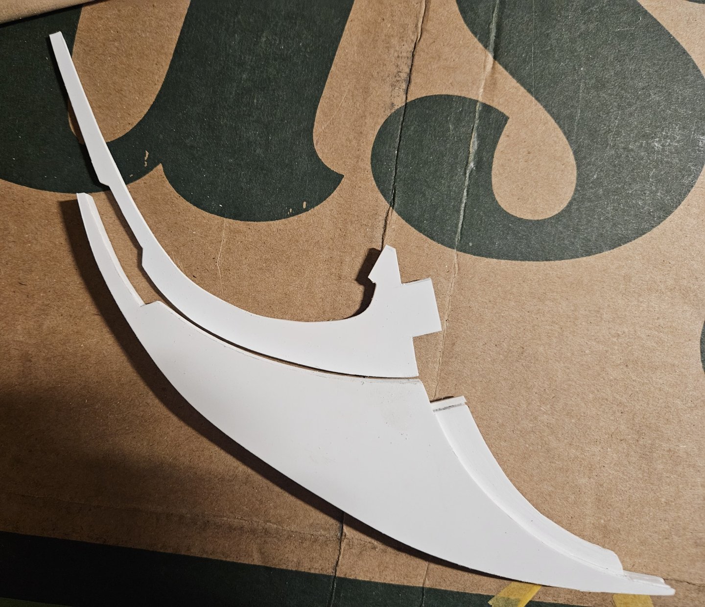
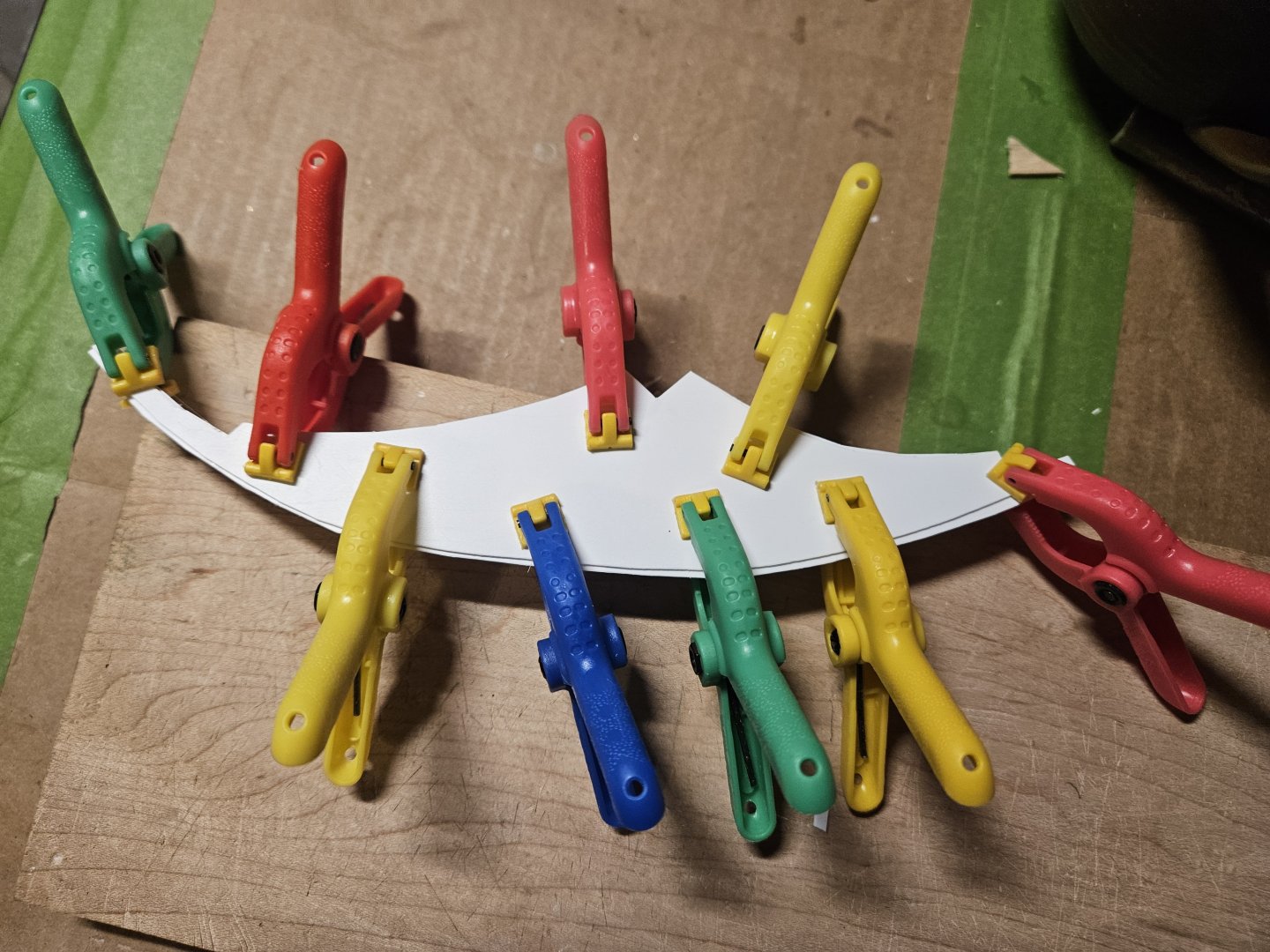
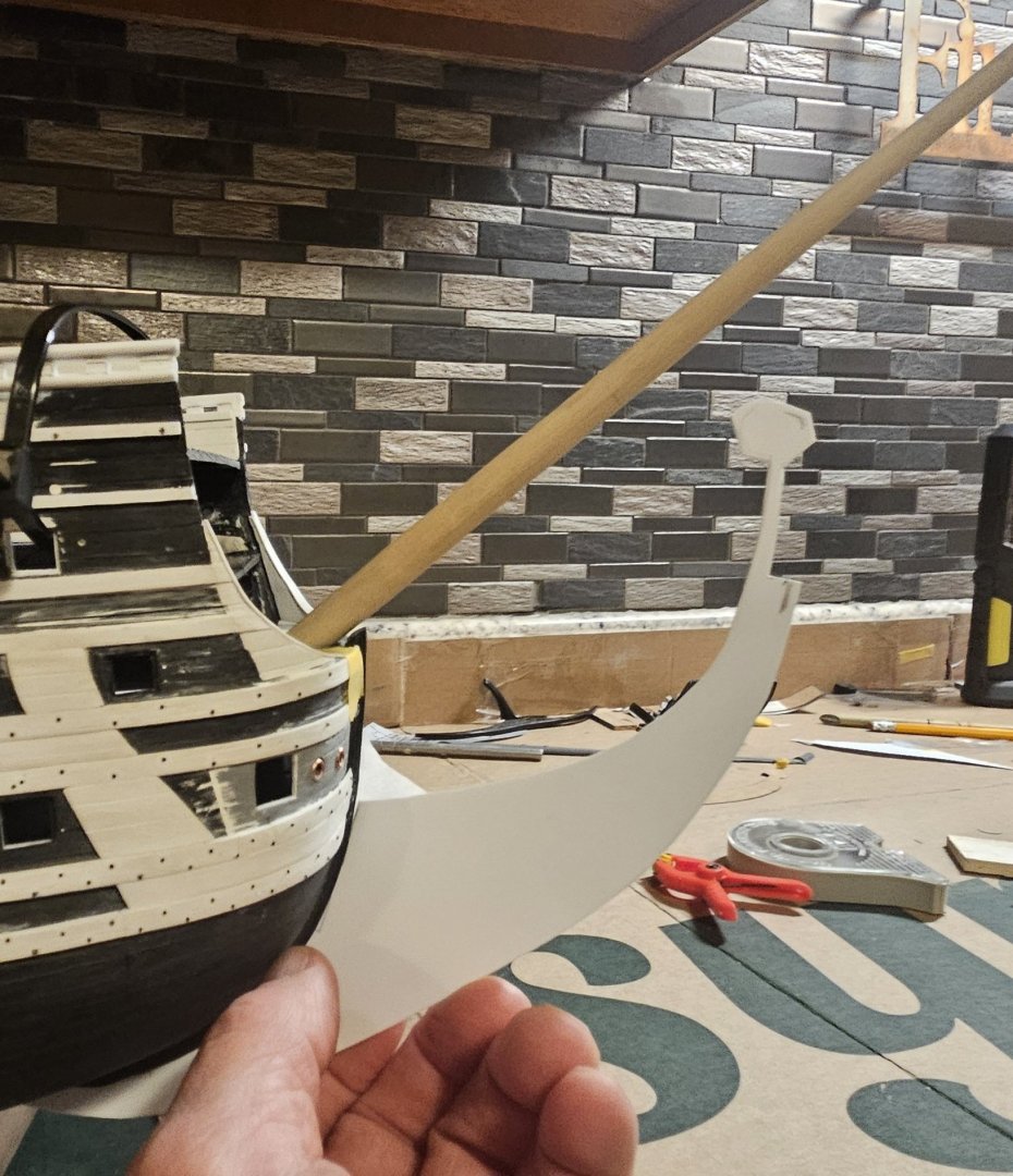
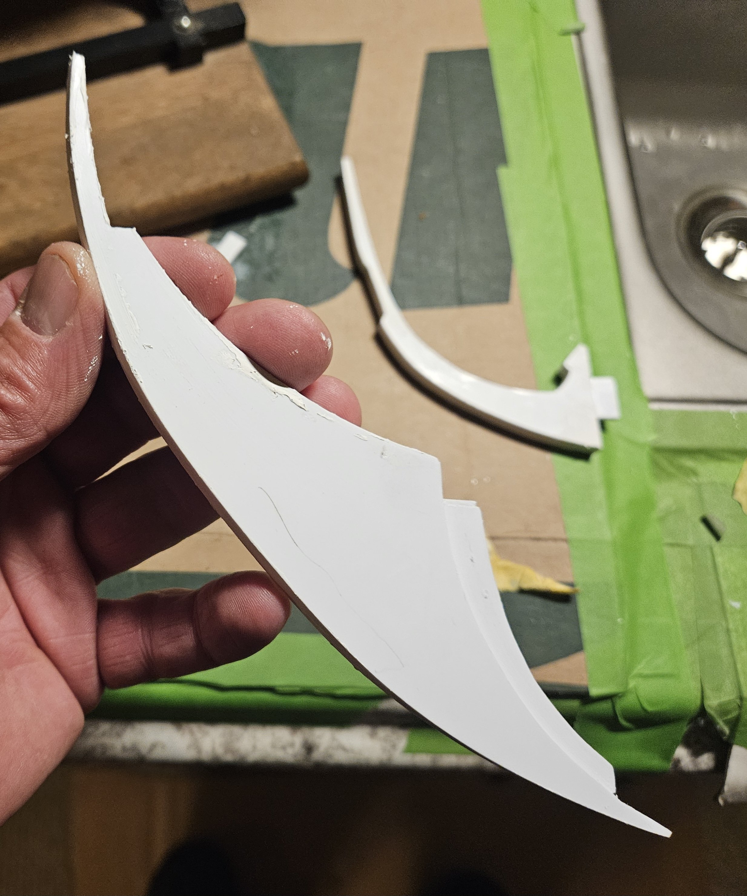
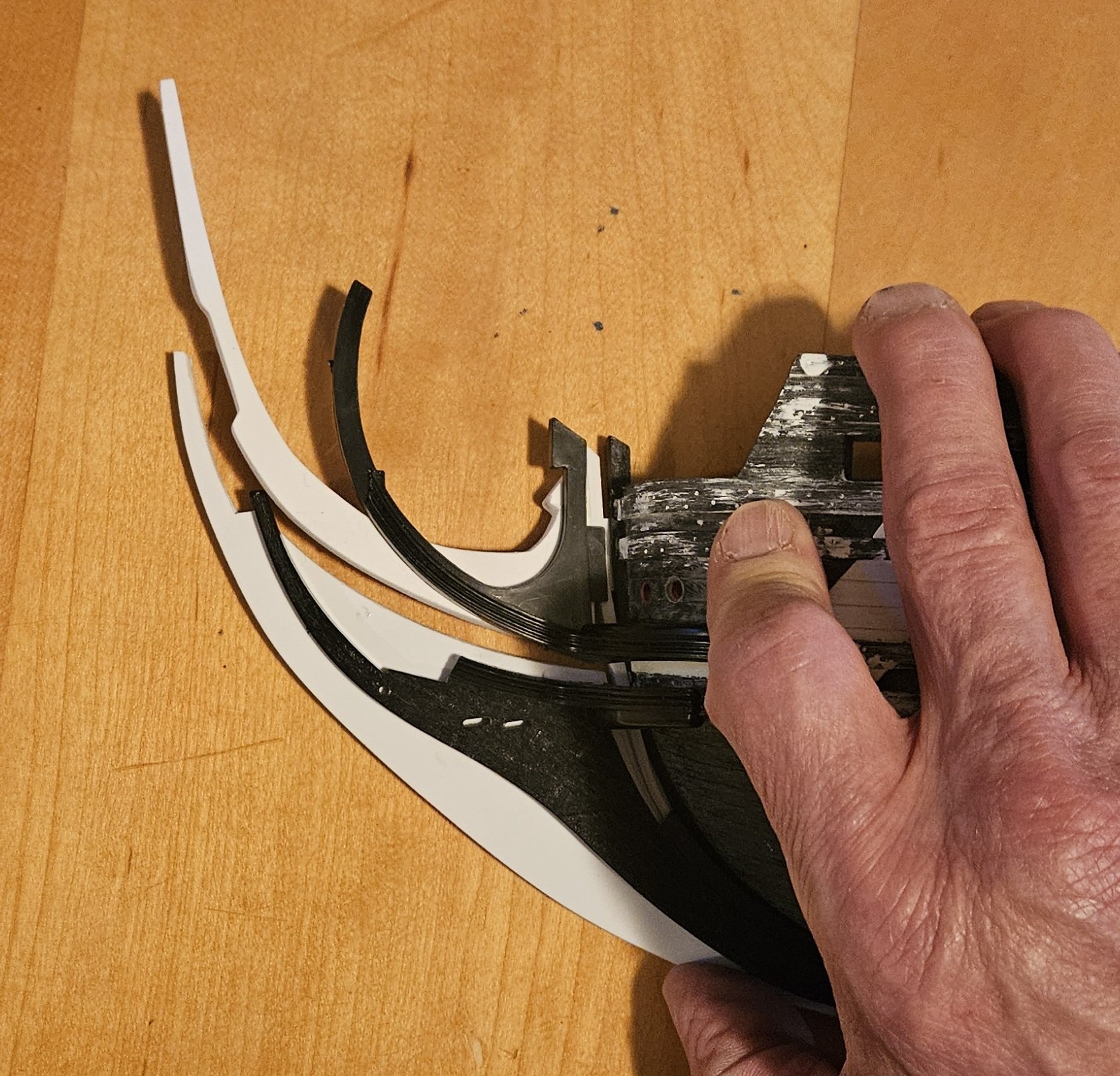
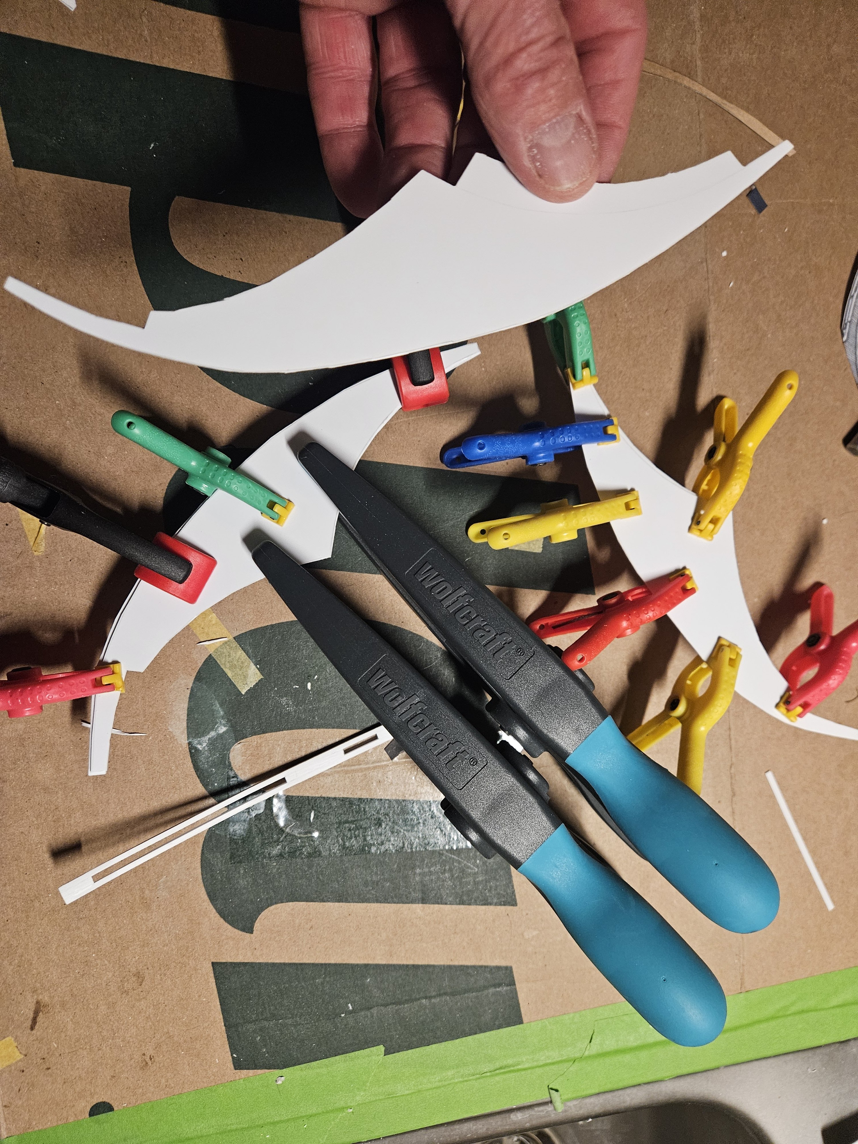
Haven't been able to get any ship time for ten days! After numerous tweaks, I finally settled on a cardboard template design for the cutwater. I need the cutwater to be 6.5mm at its thickest, so I used eight templates of various Evegreen sheet thickness to start laminating together. Finally, I ended up with three main pieces... two outer pieces in the bottom of the photo are identical to the piece that I am holding, except that this piece has an extension tab added to it to allow me to insert the tab into the hull for greater strength (just like the kit design). Finally, with the figurehead taped in place and the cutwater inserted into the hull through the stem extension piece...... I have a cutwater. Certainly there is a lot of faring and fine-tuning to do, but the basic structure is set. Having this in place will make designing the upper knee and head rails mucvh, much easier.


- 432 replies
-
- 5
-
-

-
- soleil royal
- Heller
- (and 1 more)
-
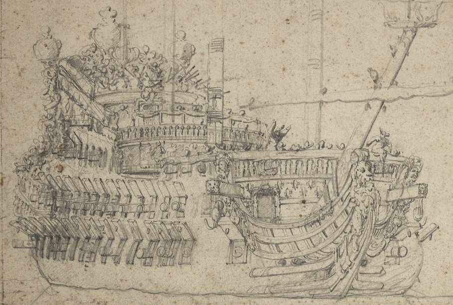
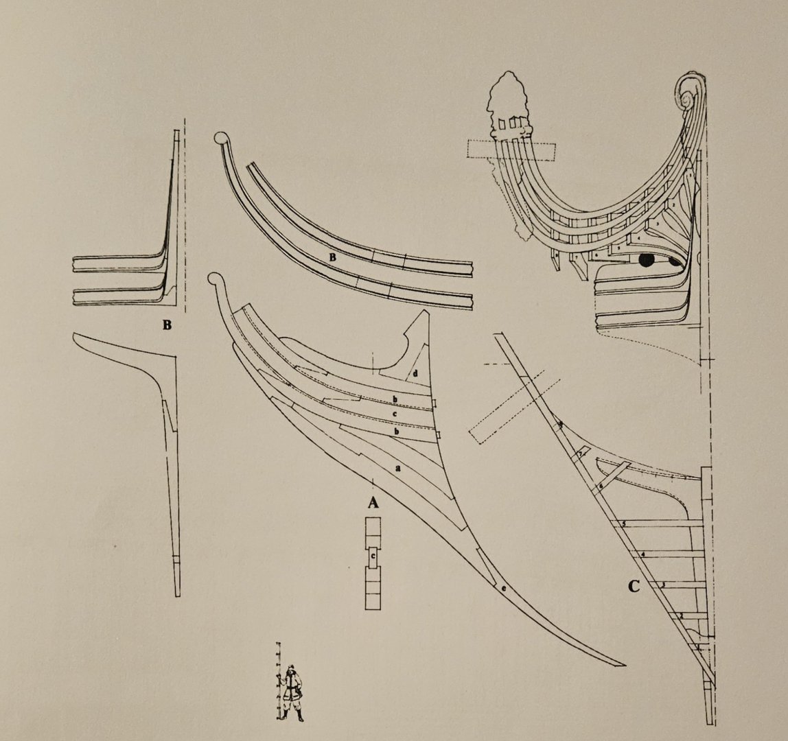
Here is that Plate from St Phillipe... at the bottom center (below the "A") is a straight on view of the head/cutwater. The plank labeled "c" is between the upper/lower knees and seems to indicate a thinner width board/plank... as opposed to there being nothing at all between the knees.
- 432 replies
-
- 2
-
-
- soleil royal
- Heller
- (and 1 more)
-
Thank you, Marc.. and I believe that the other masts will - eventually - have such a coming around them as well? Also, regarding the space between the upper and lower knees... was this always 1) completely open and filled with a carving, or 2) or was the gap not.open, but filled with a thinner board that carvings/frieze was then applied to? I think the St Phillipe monograph suggests a thinner board in the gap that carvings are then affixed to?
-
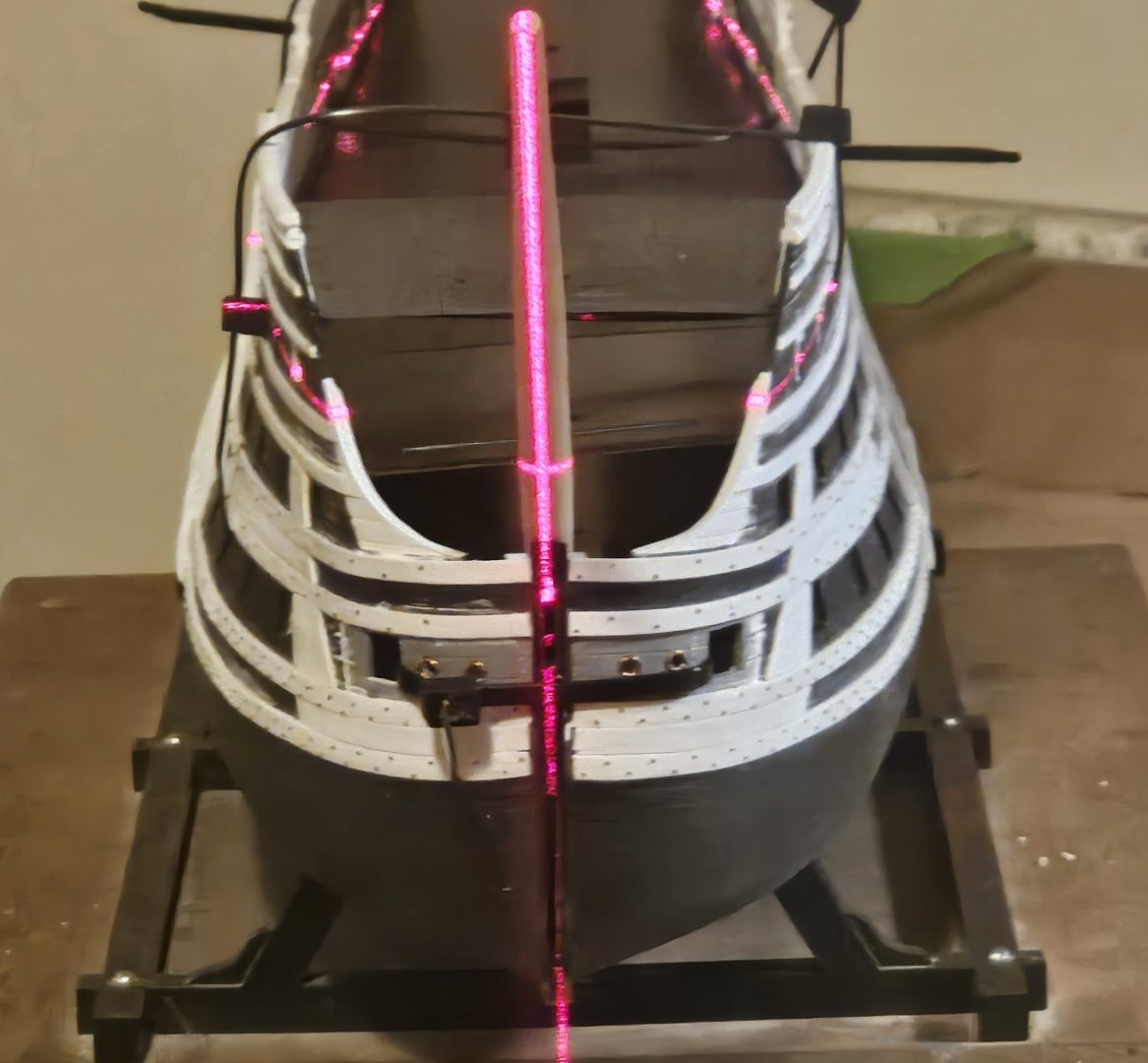
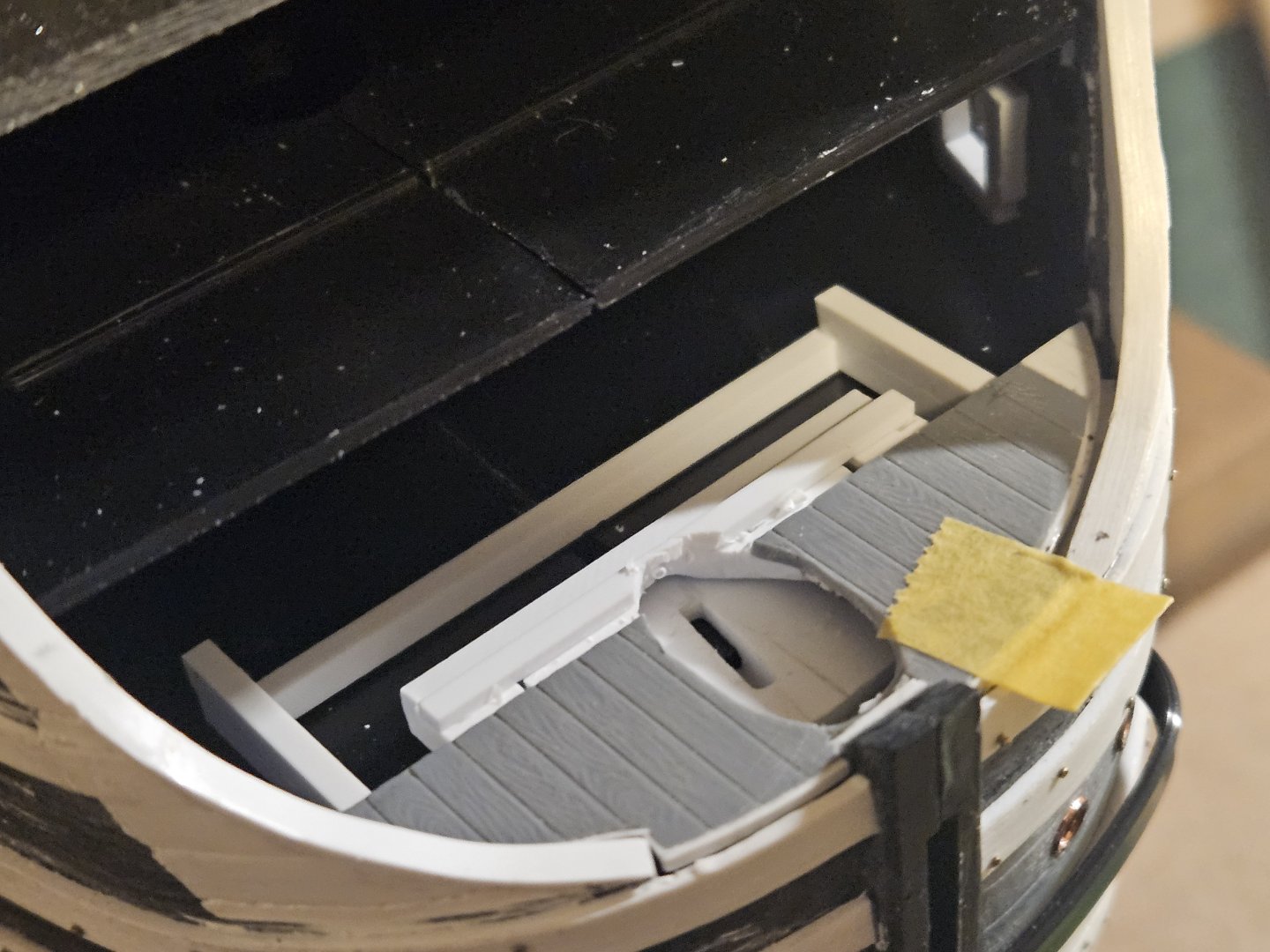
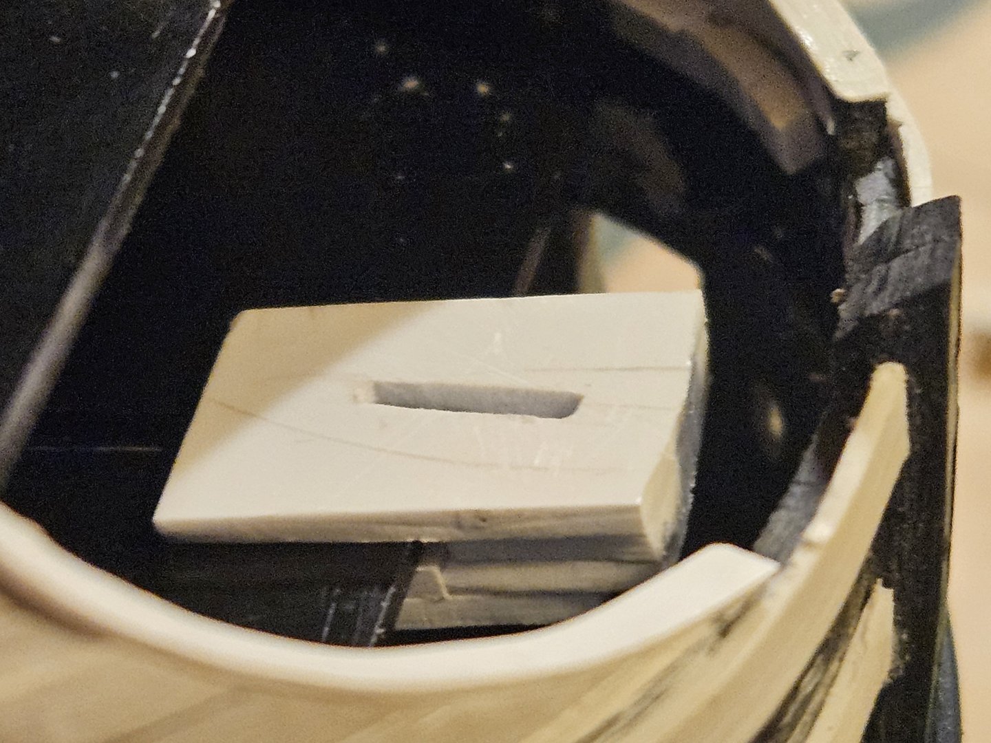
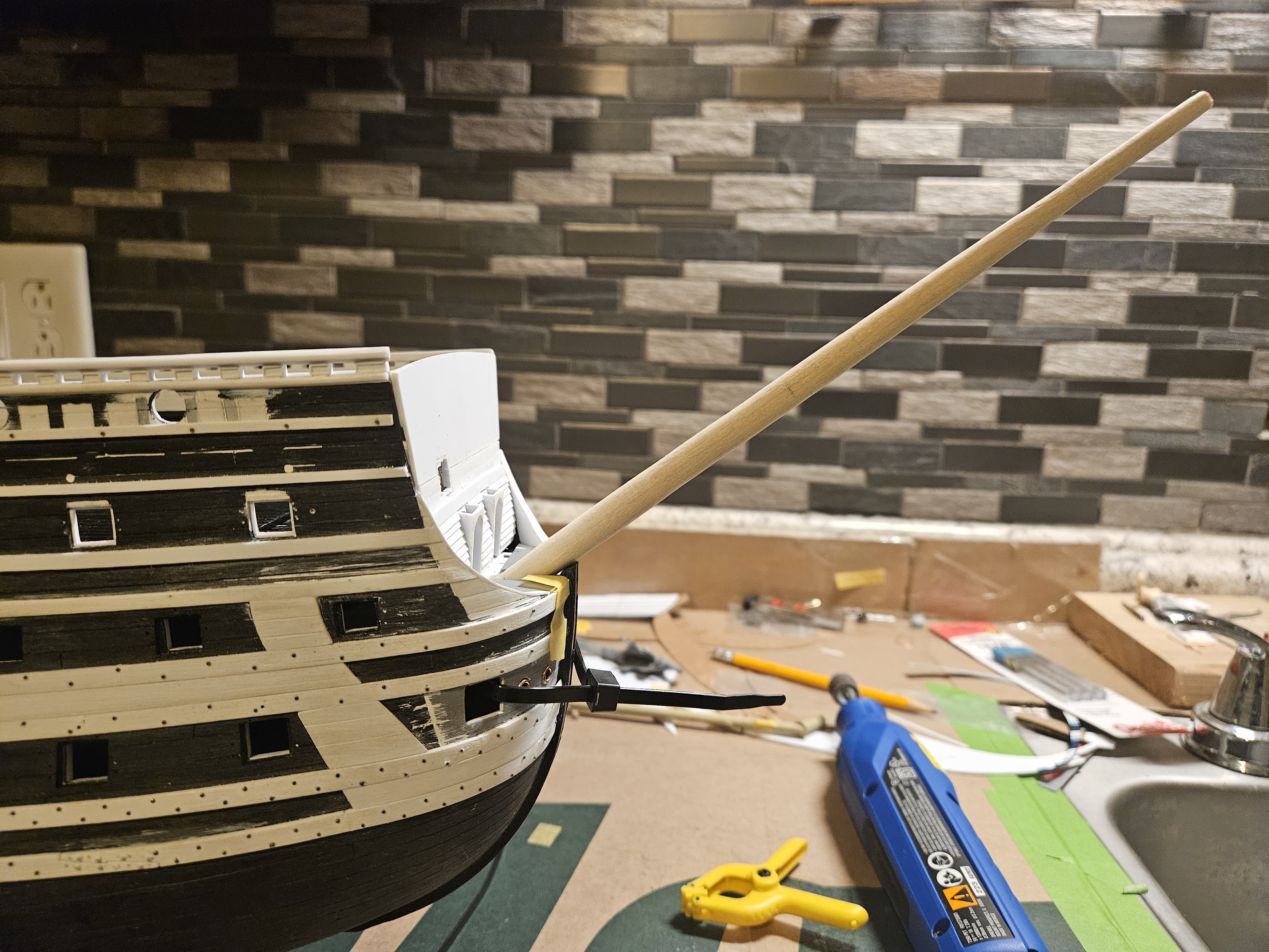
I needed to complete one final item before I could start refining the head... a solid base for my wooden bowsprit mast. I sawed a fine slot in the base of the mast and inserted a piece of styrene to duplicate the tab on the kit mast. This tab snaps into a square of styrene attached to the front edge of the middle gun deck.... the kit slot for the bowsprit mast is faintly visible to the left of the white tab, showing that the mast base moved forward about 1 inch. Then I used a laser level to make sure the base of the mast was locked onto the middle gun deck in the right position before I cemented the base in (I may even beef this up further with some ApoxieScuplt). Finally... a rough template for the head is held in place... I have some adjusting to do! My goal... develop and fit as much of the head in advance as I possibly can.
- 432 replies
-
- 6
-
-
- soleil royal
- Heller
- (and 1 more)
-
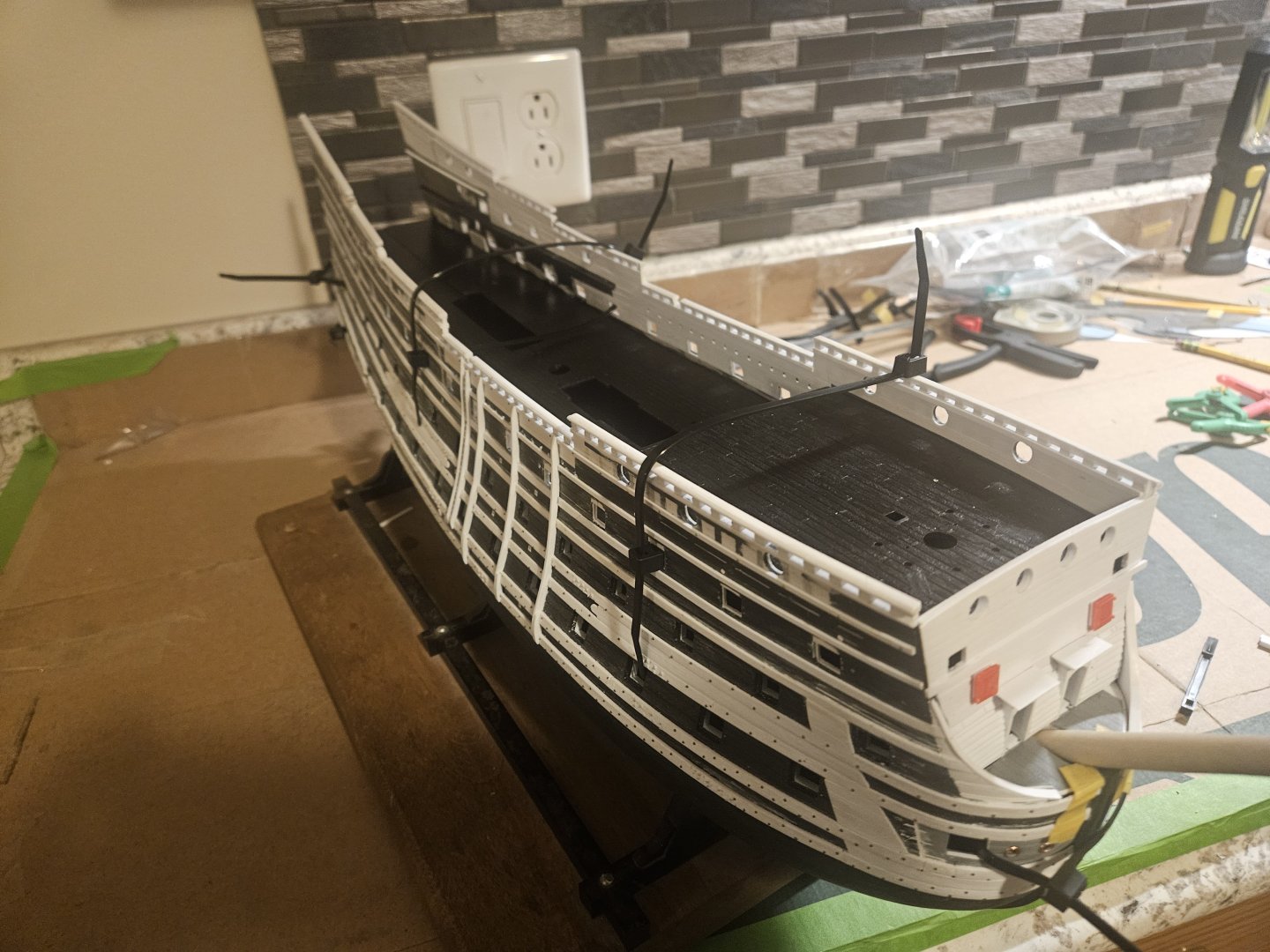
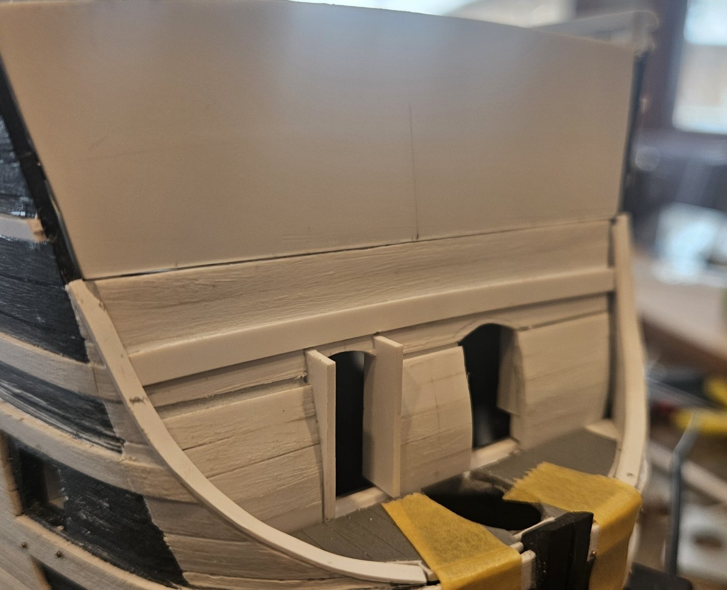
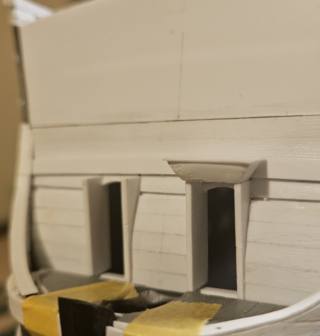
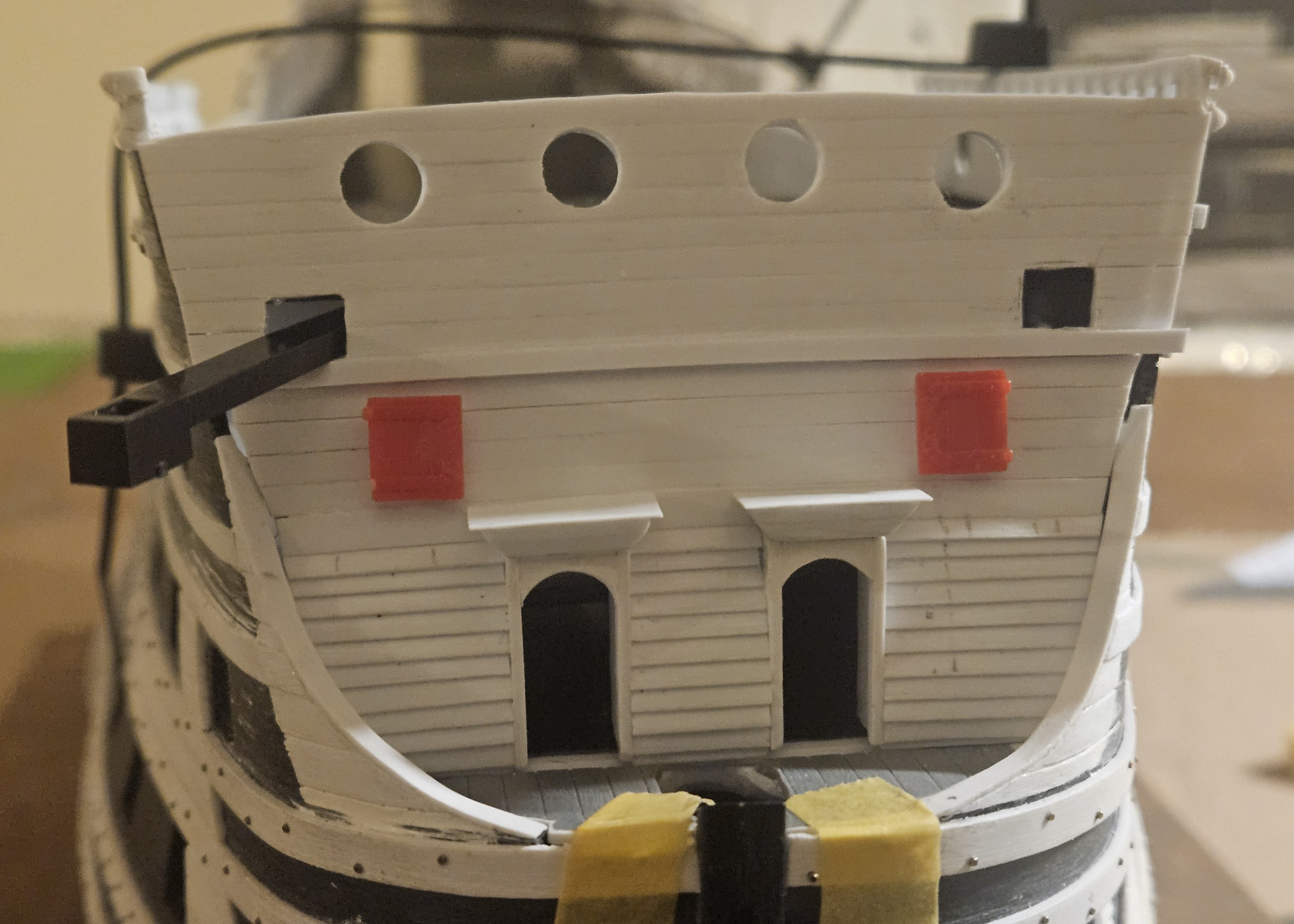
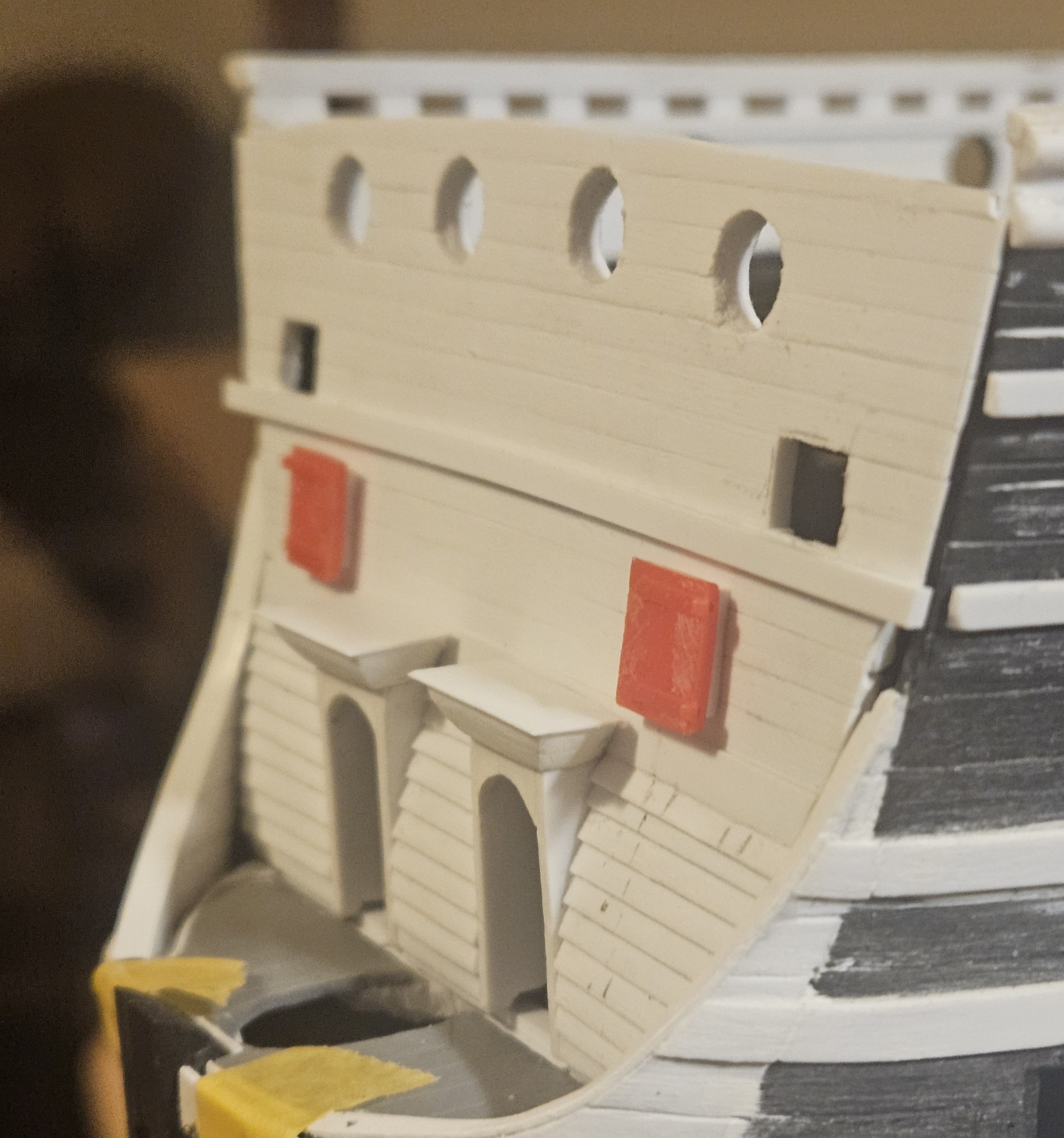
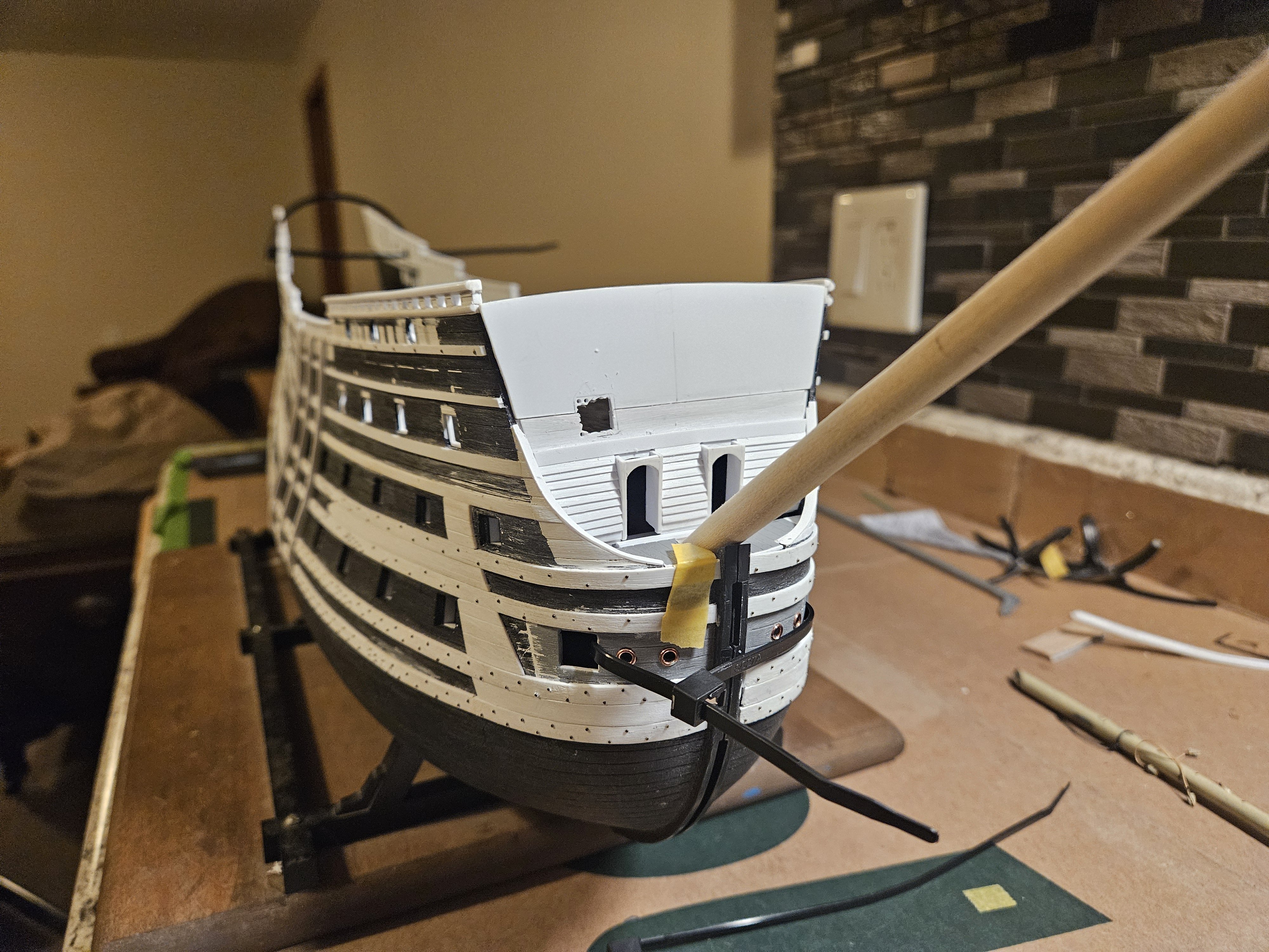
And the main structure of the beakhead bulkhead is complete. Finishing the timberheads and cap rail will be easy. I tacked the red gun port lids in place just for a visual aid. I was simply going to scribe them in, but an even simpler method is just to cut the openings in and drop the gun port lids in, and they will be closed anyways. I may make a little frame on the inside bottom of the f'ocsle deck that I can simply slide the catheads into when that time comes (2026?!). That leaves the "decoration"... the monogram La Reyne cartouche over each door, a resin casting of the Central Arms of France positioned in the center between the two rails, the continuation of the broadside listons d'or onto the bulkhead drift rail. And of course, learning how to make an egg and dart moulding for the wide rail that mates with the top upper wale. And.... waiting for the Jan Pieper book to glean any further ideas! One note that might seem to border on heresy... I will NOT be adding any steps/ladders as the kit beakhead bulkhead has. First, it strikes me as nigh impossible to clamber up those steps up and steep and high bulkhead, especially in any kind of weather action... I would just use the doors! Second, I looked at drawings of Royal Duc and Royal Louis in the 1660's/70's time frame, and I do not see any steps. And I will have a large, flat and uninterrupted area for a field of fluer de lis.... After the cap rail/timberheads are in, I can fiddle with the ornamental items, but now I can turn most of my attention to finishing the head itself. Oh... and also finishing the bowsprit. Oh - and thank you for zip ties! I had been using my 45 year old kit decks in the hull as I was checking for fit of the beakhead bulkhead and other items. I decided I better put the new decks that I will be using in place to check for fit, and zip ties helped tighten and hold everything in place.


- 432 replies
-
- 6
-
-
-
- soleil royal
- Heller
- (and 1 more)
-
Ahhh, thank you, Marc... even more things to think about for the future! My SR already seems more white than the original black (i.e. polystyrene revisions). what is some more white?!
- 432 replies
-
- 1
-

-
- soleil royal
- Heller
- (and 1 more)
-
Marc, I am very interested in burying myself in this book! I am just about to cut in the cathead openings under the f'ocsle deck... and there is so much room for ornamentation/decoration on the beakhead bulkhead alone. I believe that Dassie had a comment to the effect that SR 1671 "was suddued, but very tasteful.."... ? And that concept changed with SR 1689, as you are showing. To be more precise, I will be curious if with SR 1671, they took advantage of every possible area, like simple door jambs, etc. to decorate.. and the allegories that the decorations were meant to convey. The pictures that you have shown look like you can really see the details. P.S. and I need to look back at what you did with parchment paper!
- 432 replies
-
- 3
-
-
-
- soleil royal
- Heller
- (and 1 more)
-
1) Marc and Marcus.. I also ordered the book. I will actually hold off on decoration details until I can get the book 2) got a bowsprit made from wood! Using the St Phillipe monograph as a guide, a woodworking friend designed a jig for his lathe to reproduce all of the SR masts/yards sometime in the future. Now that I have a bowsprit, I can finished the bulkhead and pivot to the head. I really beefed up the support structures for the bowsprit deck... the bowsprit now will go into the middle gun deck some 20mm ahead of where it anchors in the kit; a simple "foot" that attaches to the middle gun deck should accomplish that. Oh.. starting to put in the two gun ports on the upper gun deck facing forward. It makes sense to me to have them open by swinging sideways as I have seen in some models/drawings, as the cathead beams will be slung above them.


.thumb.jpg.d4f38a5f1e47b628435f53b46ef46b0b.jpg)

- 432 replies
-
- 6
-
-
- soleil royal
- Heller
- (and 1 more)
-
Marcus, thank you for the compliment, but especially the link to this book!
- 432 replies
-
- 1
-
-
- soleil royal
- Heller
- (and 1 more)
-
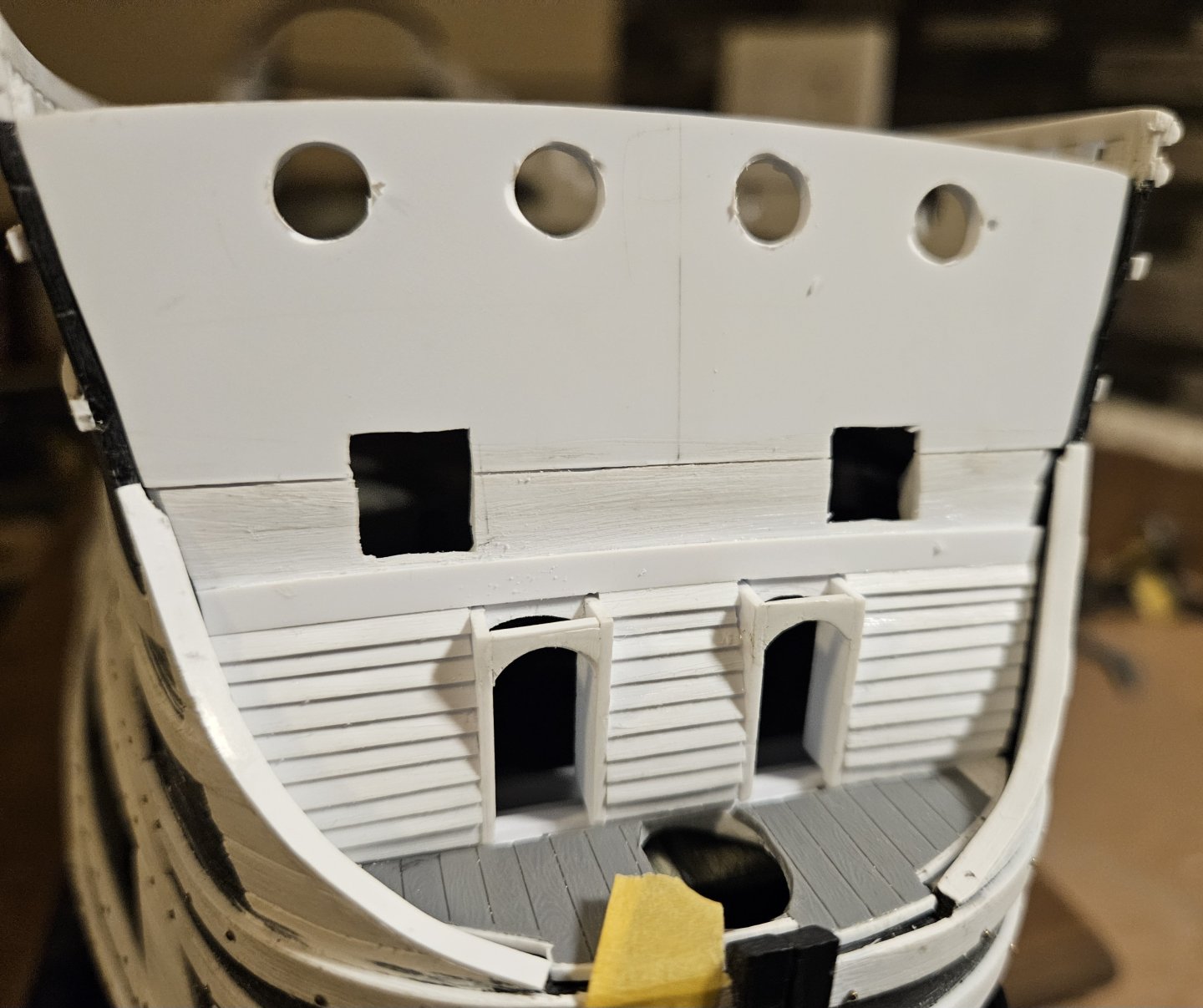
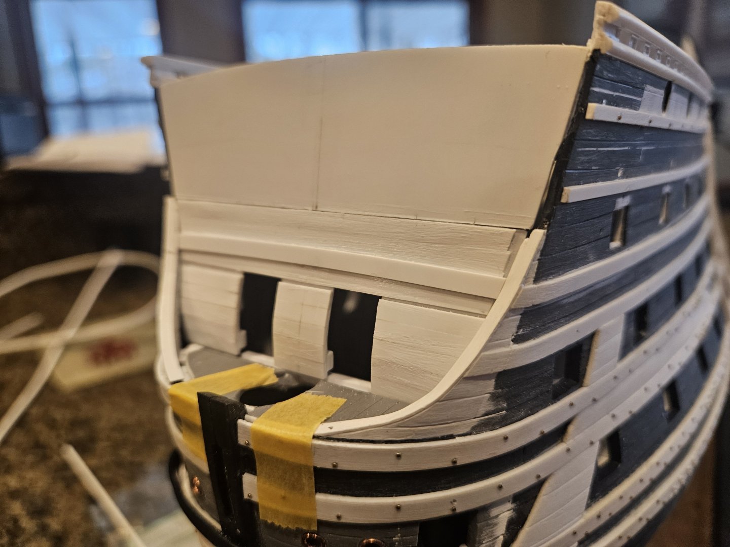
The clinker planking on the beakhead bulkhead is done. Now just the finishing touches and carefully trimming the plank edges for the best fit, and finishing the other woodwork before progressing to the upper bulkhead. So far, so good, though I am pretty sure the French carpenters would have finished their clinker planking before my miniature planking was half done!
- 432 replies
-
- 4
-
-
-
- soleil royal
- Heller
- (and 1 more)
-
Marc, thank you for the observations! I was actually studying the La Reyne drawing when your second reply popped up, as I couldn't figure out what was above the doors.... the Coat of Arms in the center is easy via resin casting, but I couldn't figure out if I was seeing animal heads or what above the doors. Also, there is something - for lack of a better term! - "squiggly" on the door frames that I was thinking of duplicating. I think I will clinker plank first to see exactly what I have to add to the door frames, and then apply the "squiggly" on top of that. Perhaps they are just some acanthus leaves twined together? I will also look at somew other drawings and models to see...
-
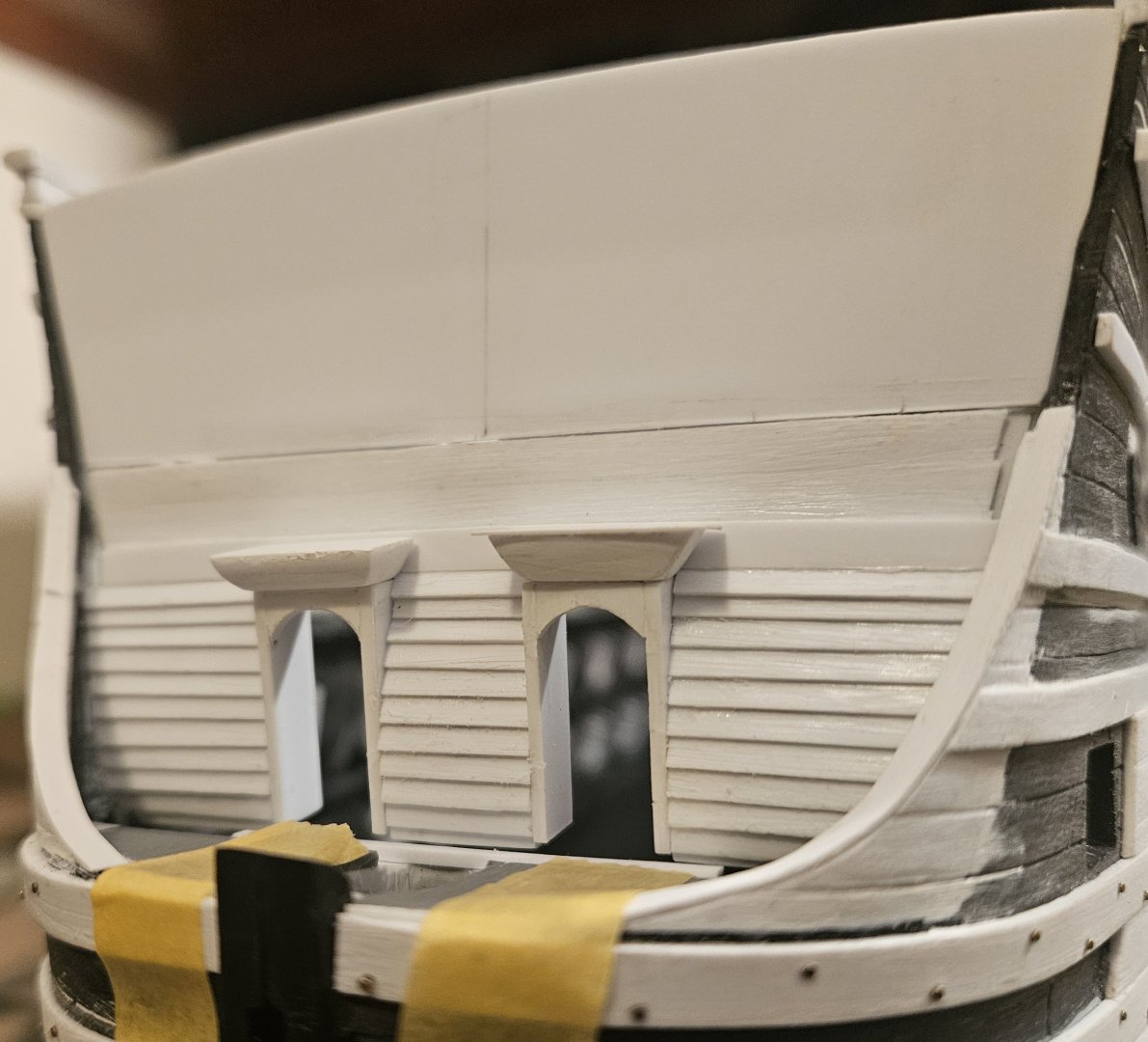
Good day for a snowstorm! A lot of fiddle work now... not sitting at the model for hours, maybe 10 minutes at a time making adjustments and letting glue dry. Applied the lower rail, and it matches up with the upper wale of the two top wales. This will eventually have an egg and dart molding on it, but I have plenty of time to study what Marc LaGuardia did on his build log. I am slowly building the doors and the frames, then I will clinker plank the lower half. I still have to cut openings for the catheads, four circular gun ports on the f'ocsle, and two gun ports on the upper gun deck. Slowly but surely...
- 432 replies
-
- 5
-
-
- soleil royal
- Heller
- (and 1 more)
-
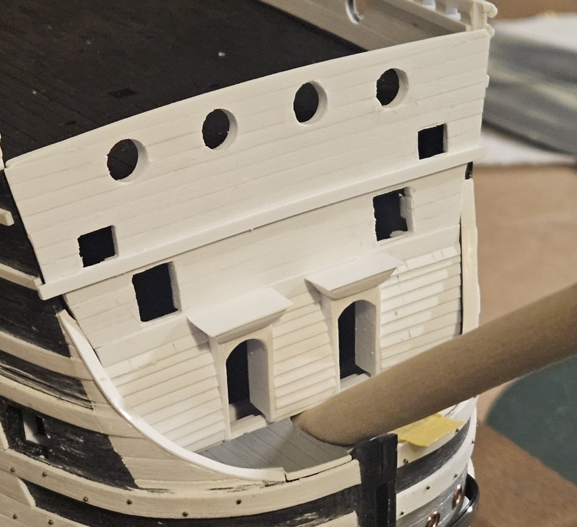
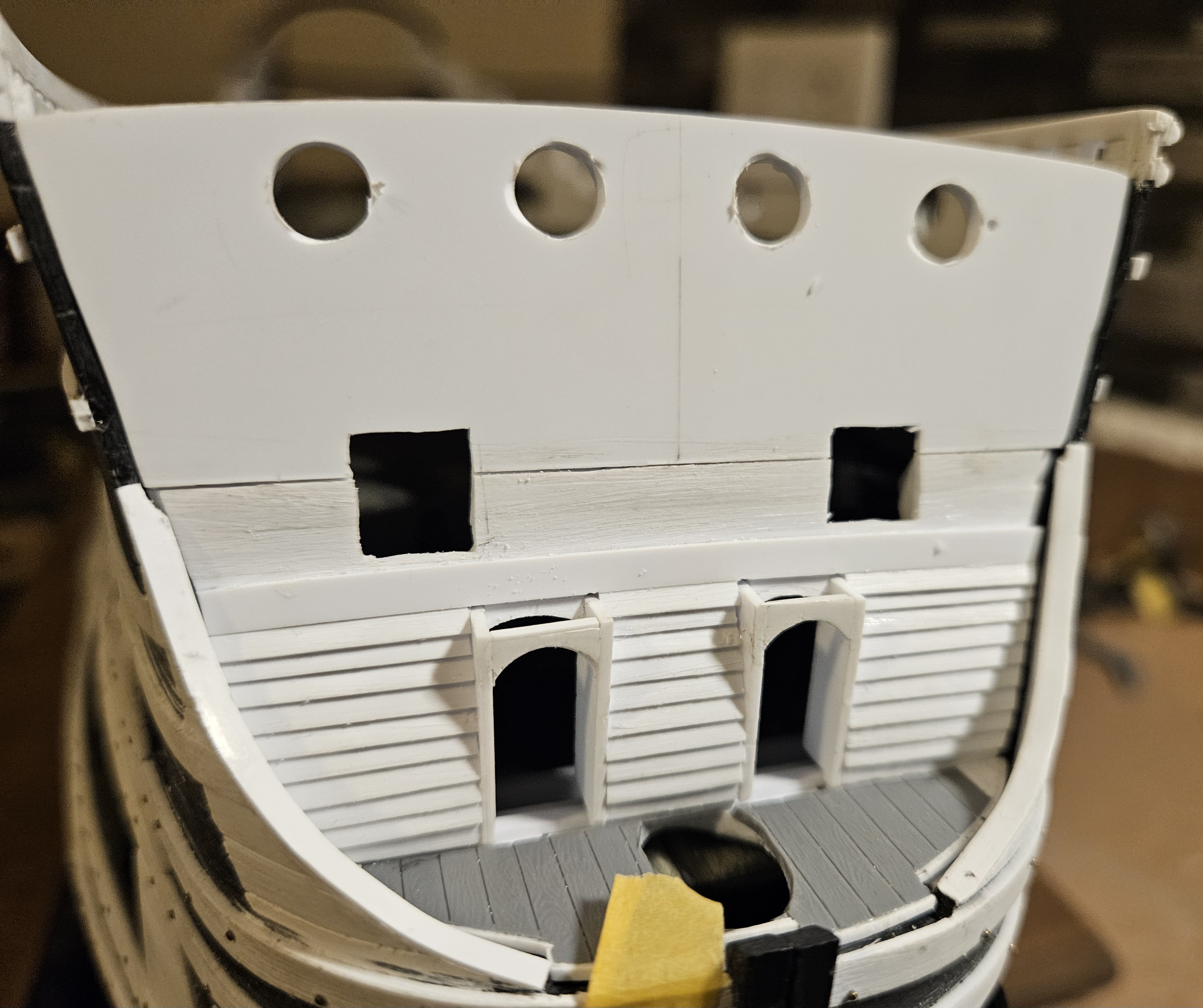
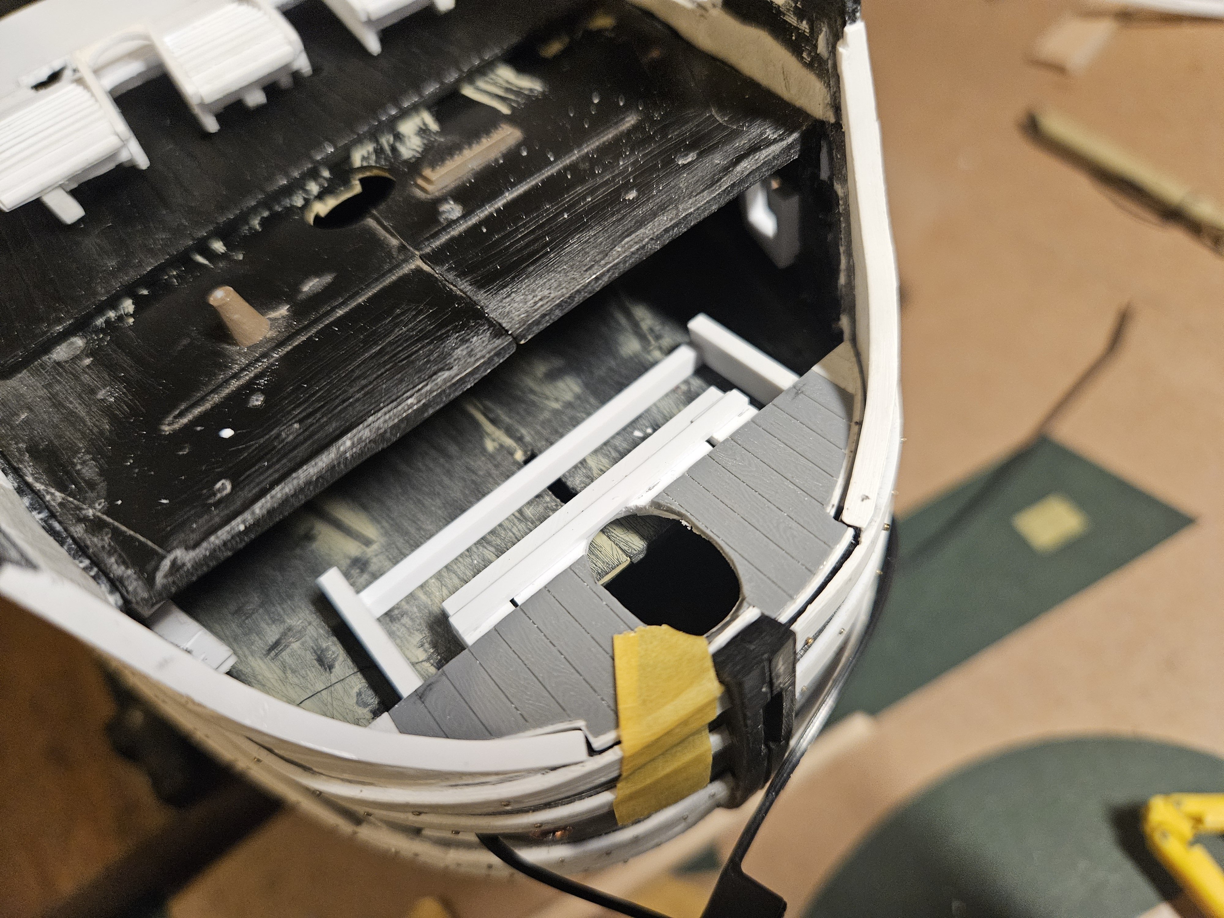
Since I have to wait for some glue to dry.. a quick update. My "proof of concept" beakhead bulkhead is in the garbage; it served its purpose, but there were some things that I wanted to correct. The first lesson was for me to make the bulkhead in two parts, and then attach them together as one piece. Also, the S-curve side profile wasn't quite what I wanted, so I started again with the lower half of the bulkhead. This strikes me as much better. The planking you see is not the finished planking, but what I would call "strength" planking to thicken the bulkhead and keep it from flexing. I also started drilling the bowsprit hole in the bowsprit deck. I still have a ways to go in gently shaving the hole into an oval shape, but I realized I better fasten some styrene pieces on the underside of the deck to strengthen the deck before I started to make the ellipse any larger. If I have calculated correctly, the bowsport will just kiss the very bottom of the beakhead bulkhead; maybe, maybe not! Now on to starting the top half of bulkhead - and I can also start framing the doors. My doors will be closed, so I don't care about the framework and support brackets on the inside of the hull showing up.
.thumb.jpg.b77820dab3d495b70e59c4bc232108b8.jpg)
.thumb.jpg.5d13fec2c9f9364d59188de077e07e43.jpg)
.thumb.jpg.2b12f1a5e66e52c48889146dafff5722.jpg)
- 432 replies
-
- 2
-
-
- soleil royal
- Heller
- (and 1 more)
-
Marc, that does look like a fascinating book... and you are right - I can't find a single copy for sale!
- 432 replies
-
- 1
-
-
- soleil royal
- Heller
- (and 1 more)


.jpg.99180c2fa567d317e2e8474472b0d216.jpg)


.jpg.3b75b185e7f6070ff1b600cf0e9880f8.jpg)
.jpg.be925dcb0d2292b5b494716207733515.jpg)
.jpg.b2e844fd66a51c5c8b0d1fc76da48db5.jpg)