EricWiberg
-
Posts
224 -
Joined
-
Last visited
Content Type
Profiles
Forums
Gallery
Events
Everything posted by EricWiberg
-
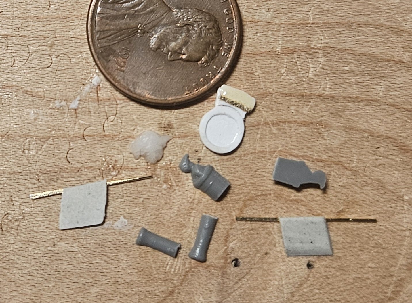
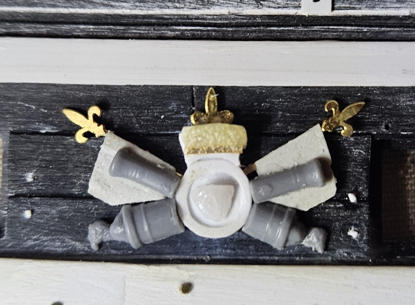
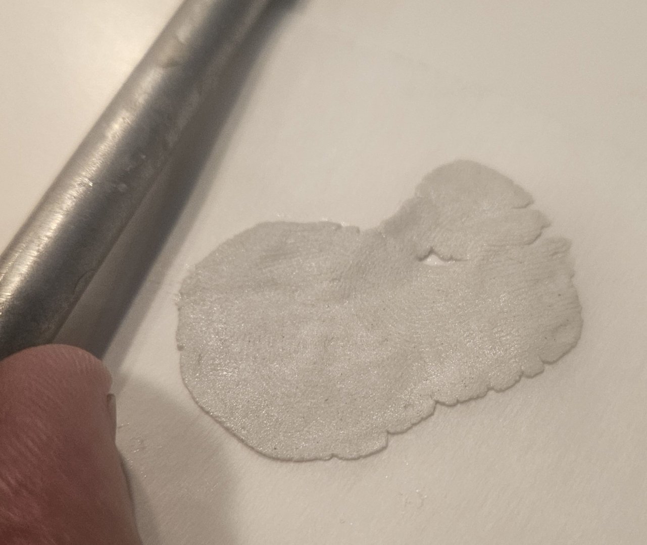
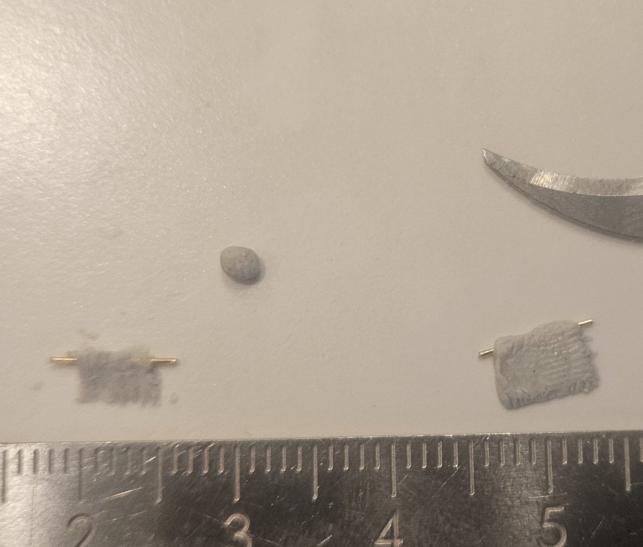
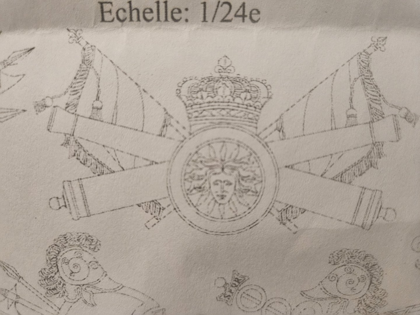
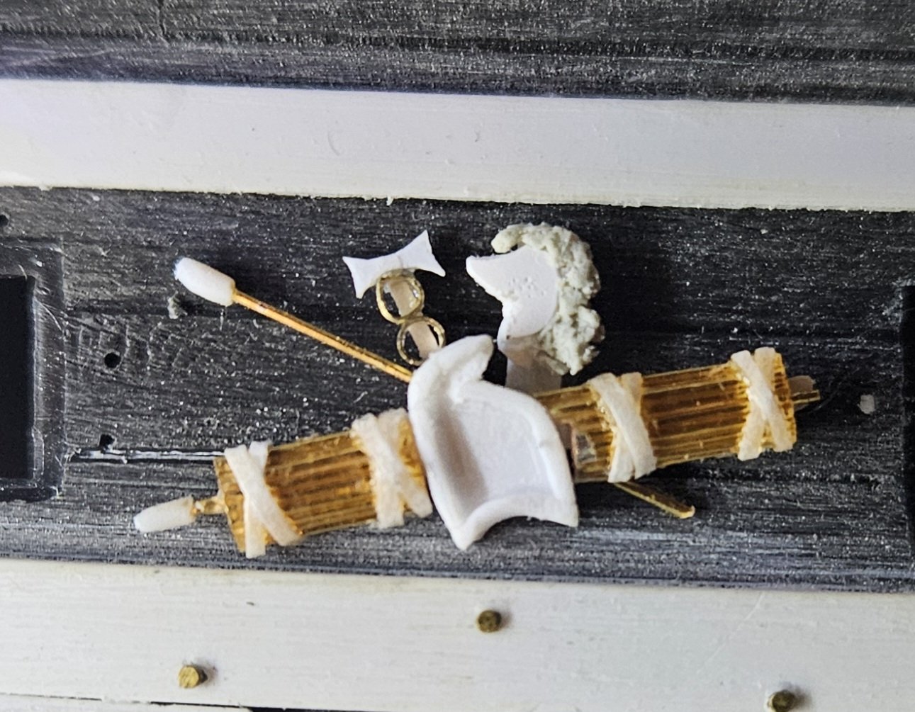
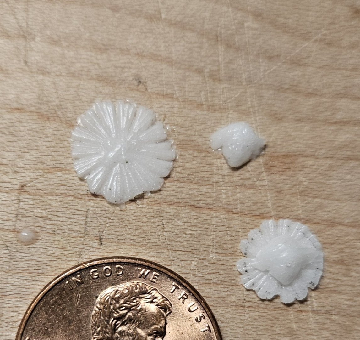
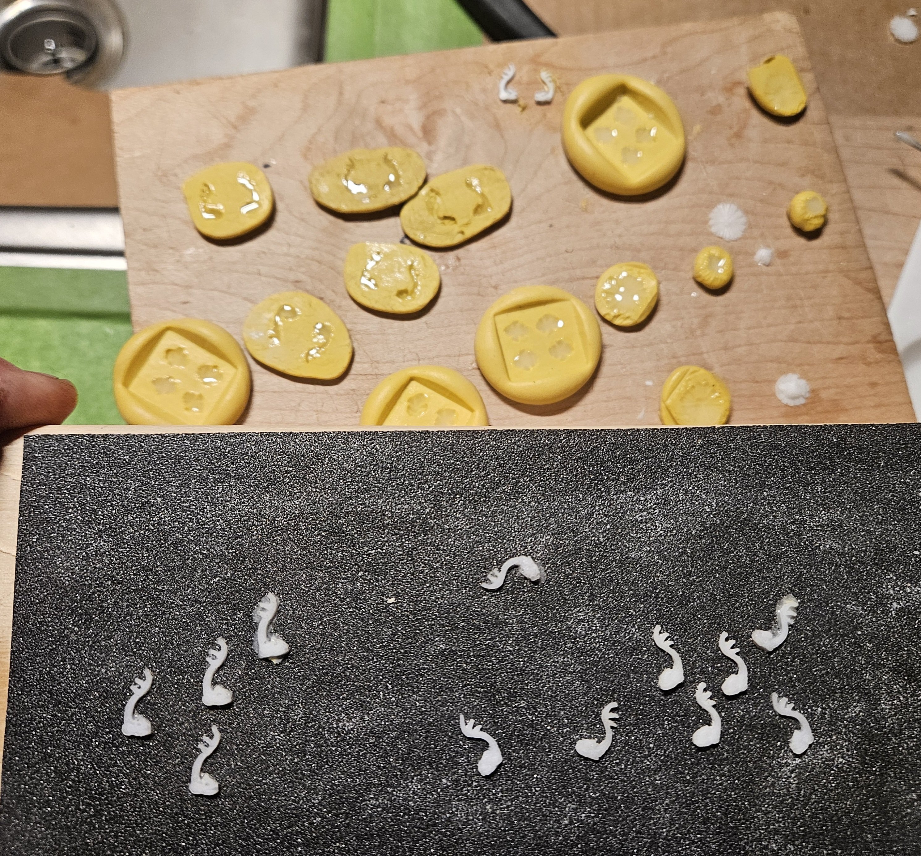
The 5th set of Trophy's Of War is completed... Up veeerryyy close, I can still see things that I am not happy with. The resin casting in the center was made from a head on on of the kit quarter gallery pieces, but it just doesn't show precise features at this scale. On the other hand, when you zoom out to a normnal viewing distance... it doesn;t seem to matter. The TOW in the center is what I was trying to create... I think my technique for making the flags was helpful (roll ApoxieSculpt out into paper thin sheets and then freeze it). I also used some 8# cannon pieces from the kit to make the cannon barrels. Here are the various pieces before assembly - minus the tiny fluer de lis that are on the flag poles and the crown.

- 432 replies
-
- 4
-

-
- soleil royal
- Heller
- (and 1 more)
-
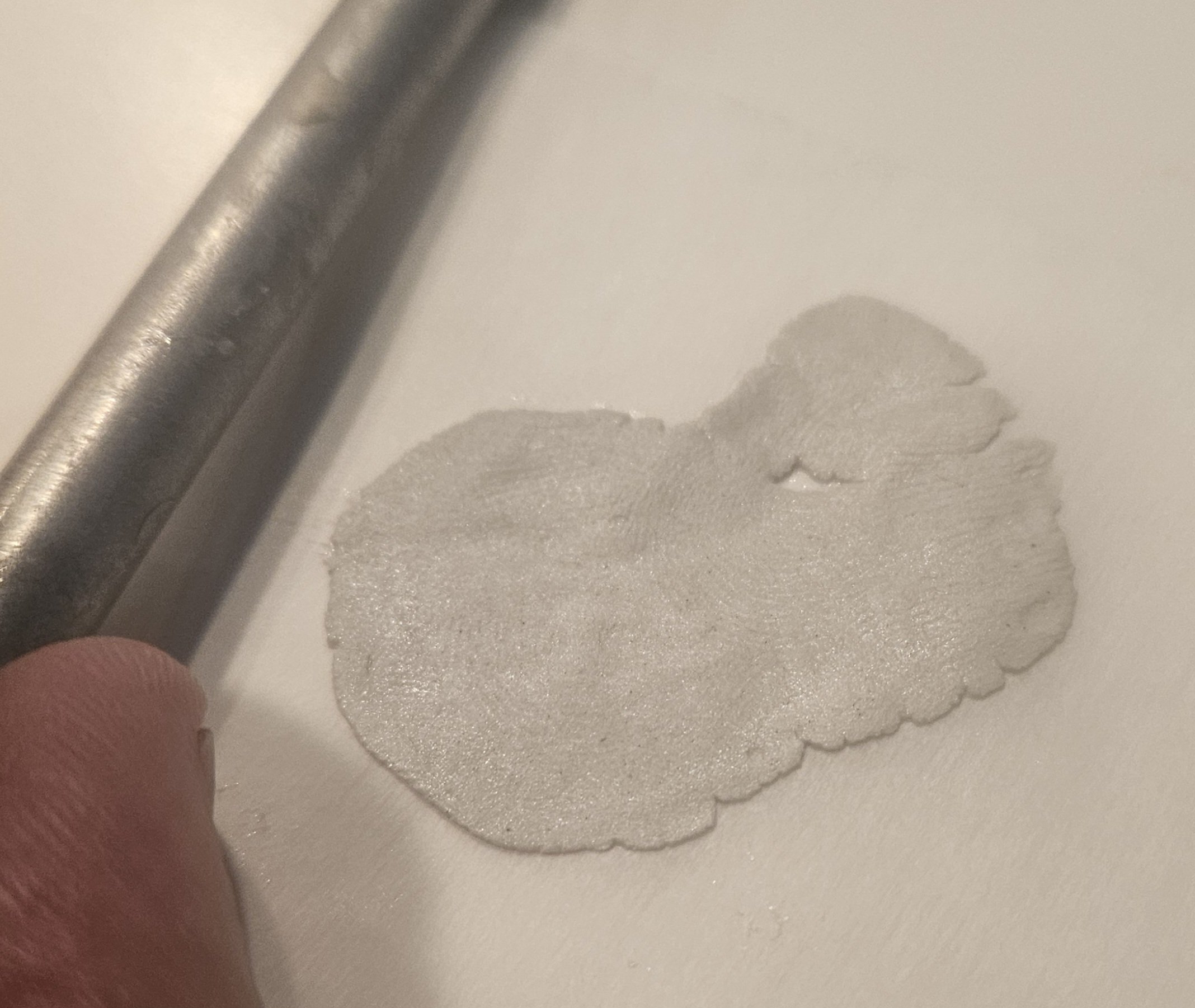
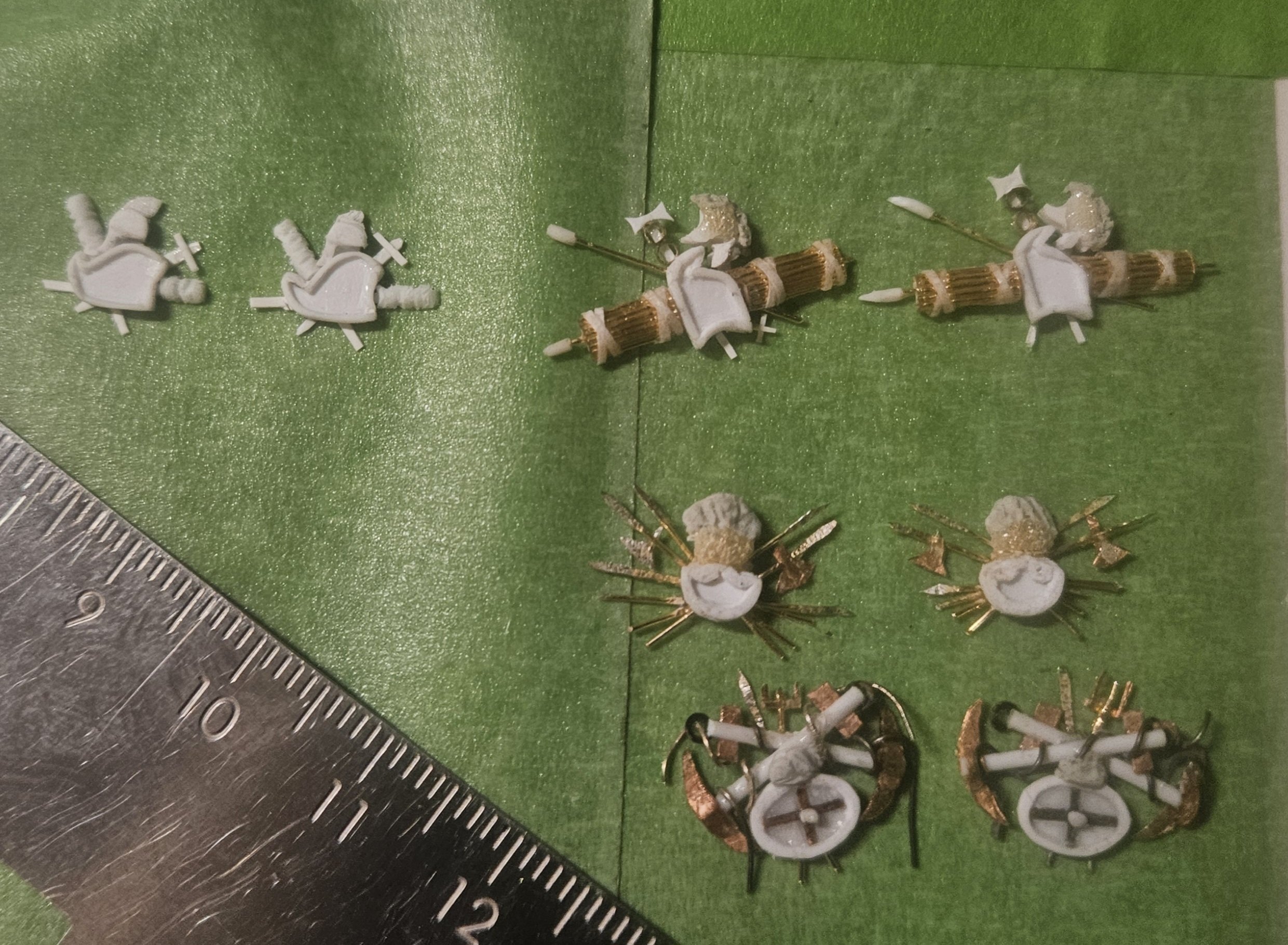
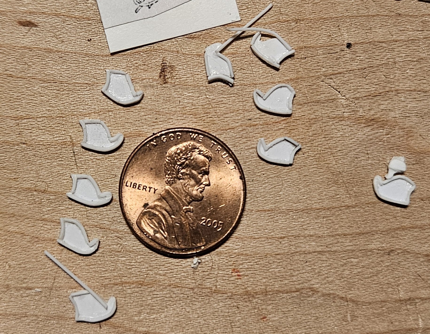
Here are the four (mostly) finished Trophies Of War (out of thirteen total TOW). I decided that I need to learn how to make flags next, as three of the TOW have flags like this... I can't remember what video I saw on YouTube, but a modeler was making a WW2 tank in 1/32 scale, and he made tarpaulins to cover parts of the tank. He didn't show how he made them, but I figured that ApoxieSculpt could be rolled out paper thin. I soaked my roller in ice water, which is something that Doris said she did, and it seemed to help. The flags need to be approximately 5mm x 4mm in size... And the first practice attempt at wrapping the flag on a staff and trying to create tassels on the edges of the flag... it probably will help if I put the tiny flags in the freezer for a bit before I attempt to work them, as that will make the flags stiffer and less pliable. Regardless, it looks like this technique of making flags will work for me, and the task will be much easier than I thought.


- 432 replies
-
- 7
-
-
- soleil royal
- Heller
- (and 1 more)
-
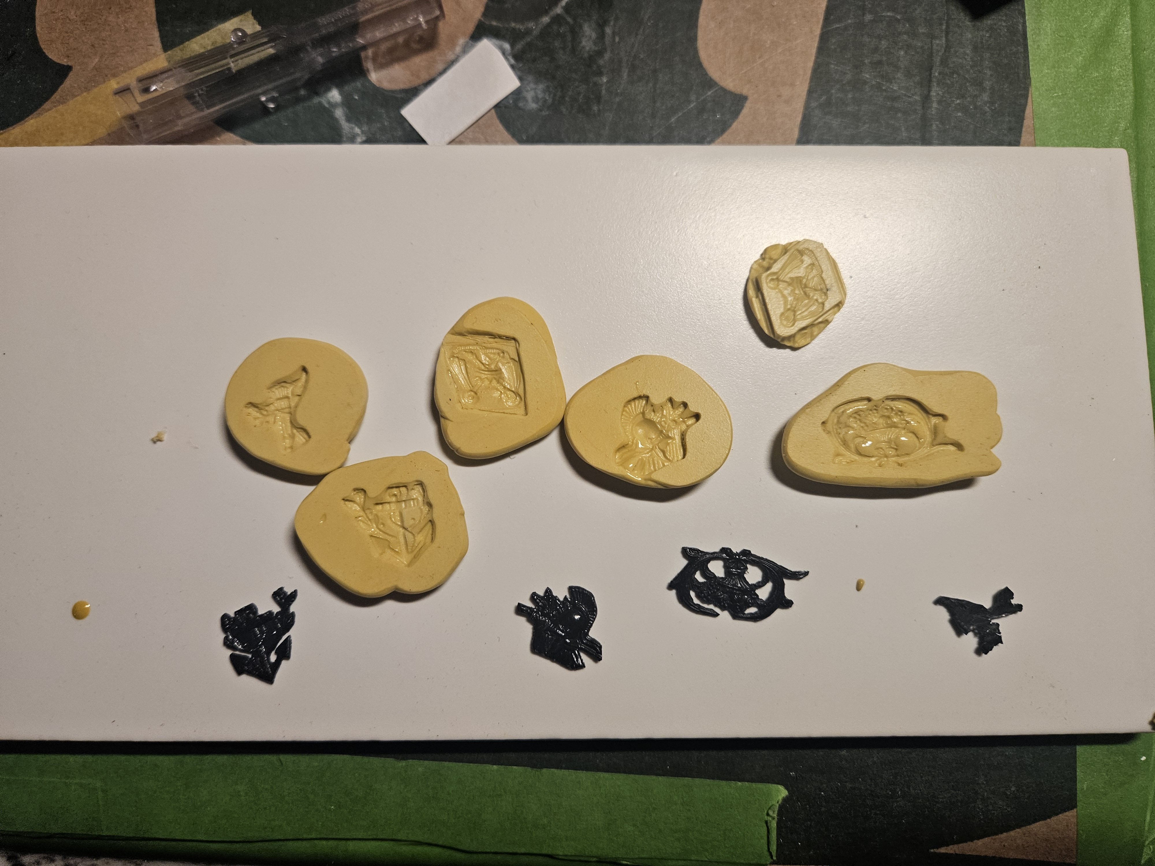
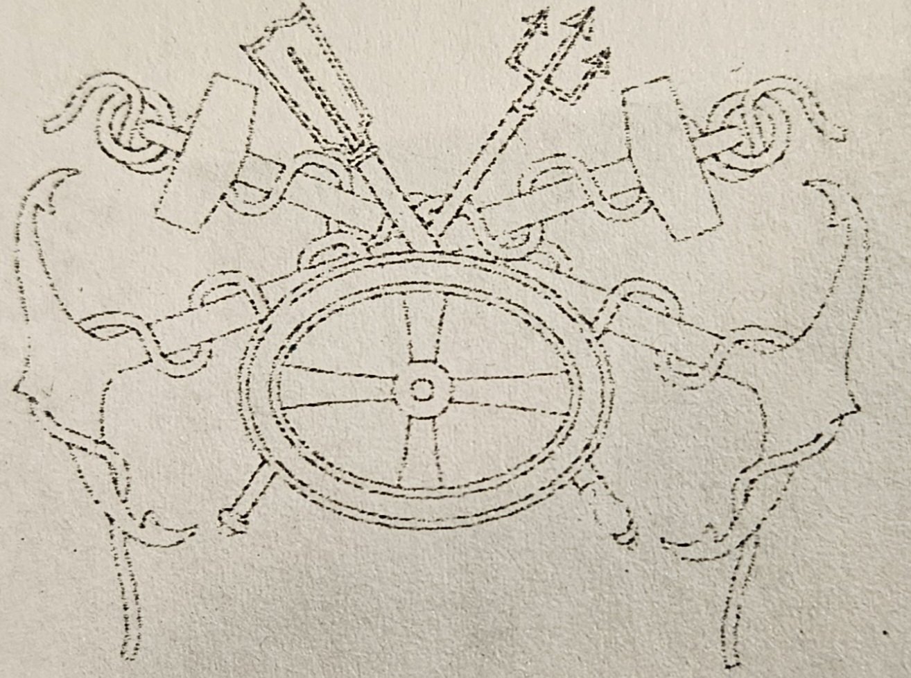
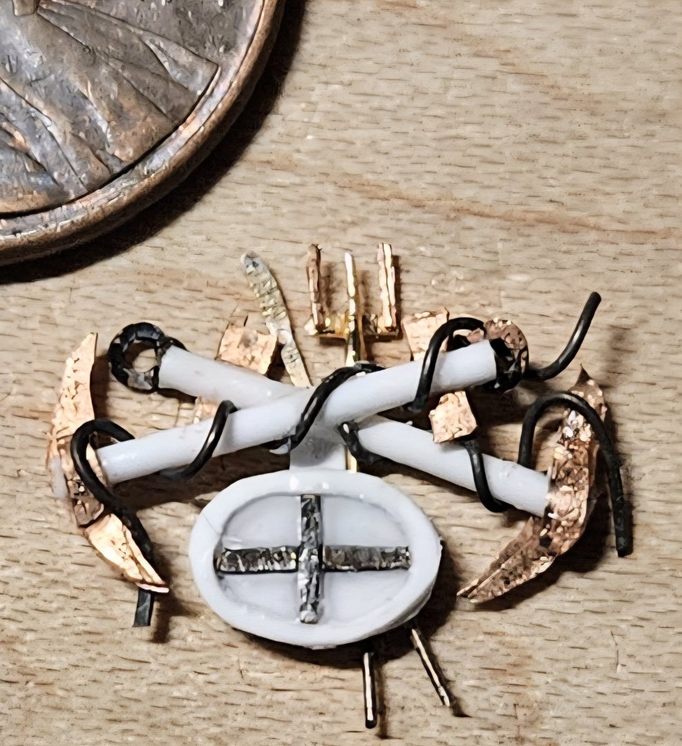
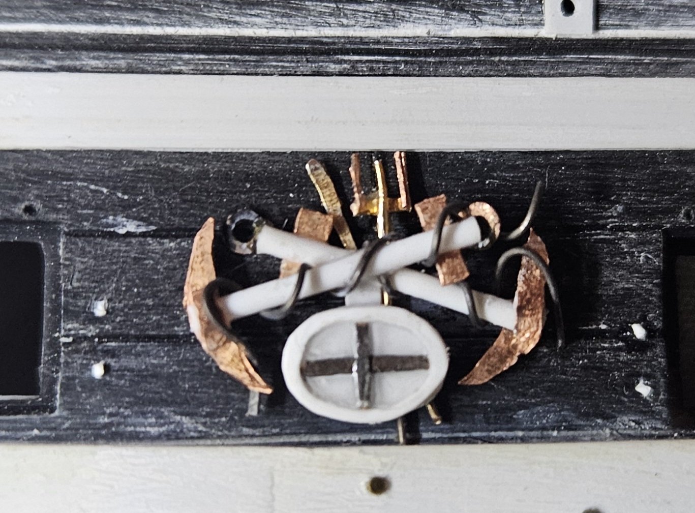
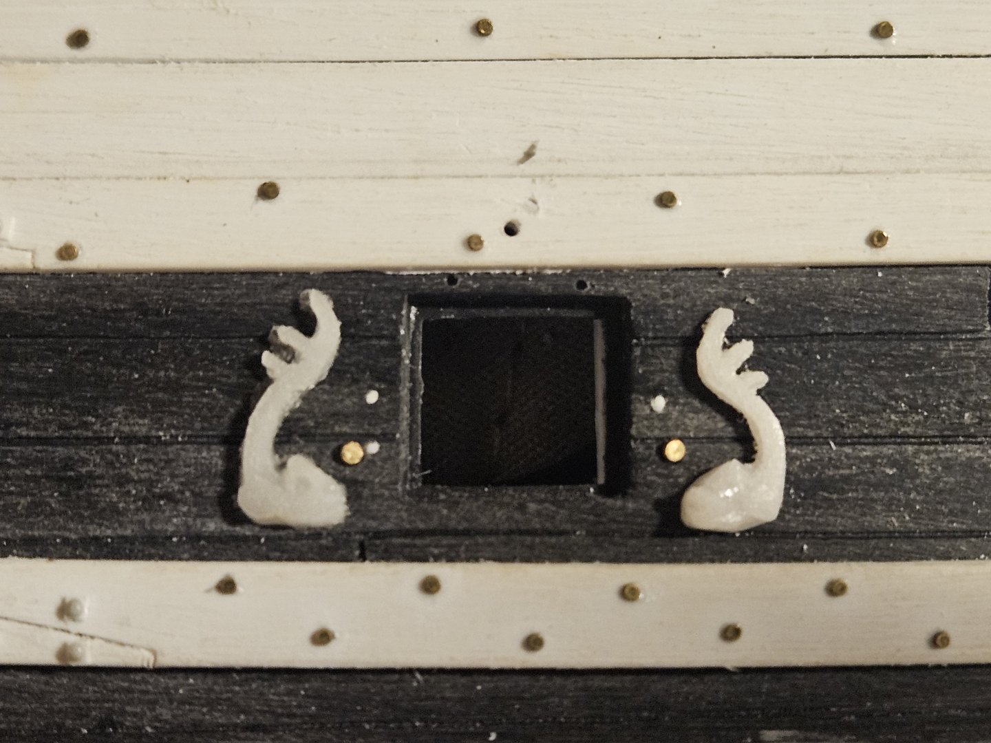
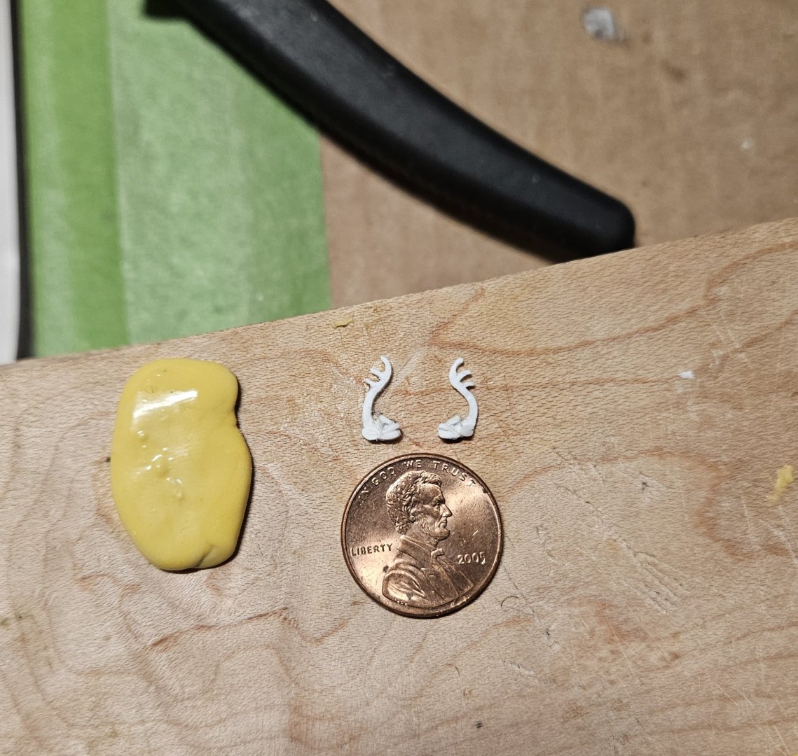
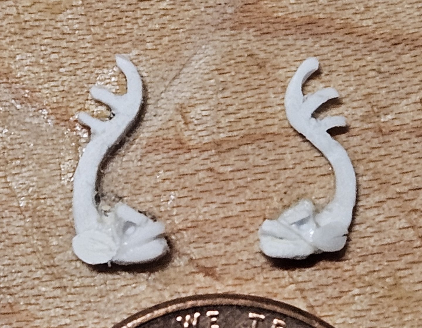
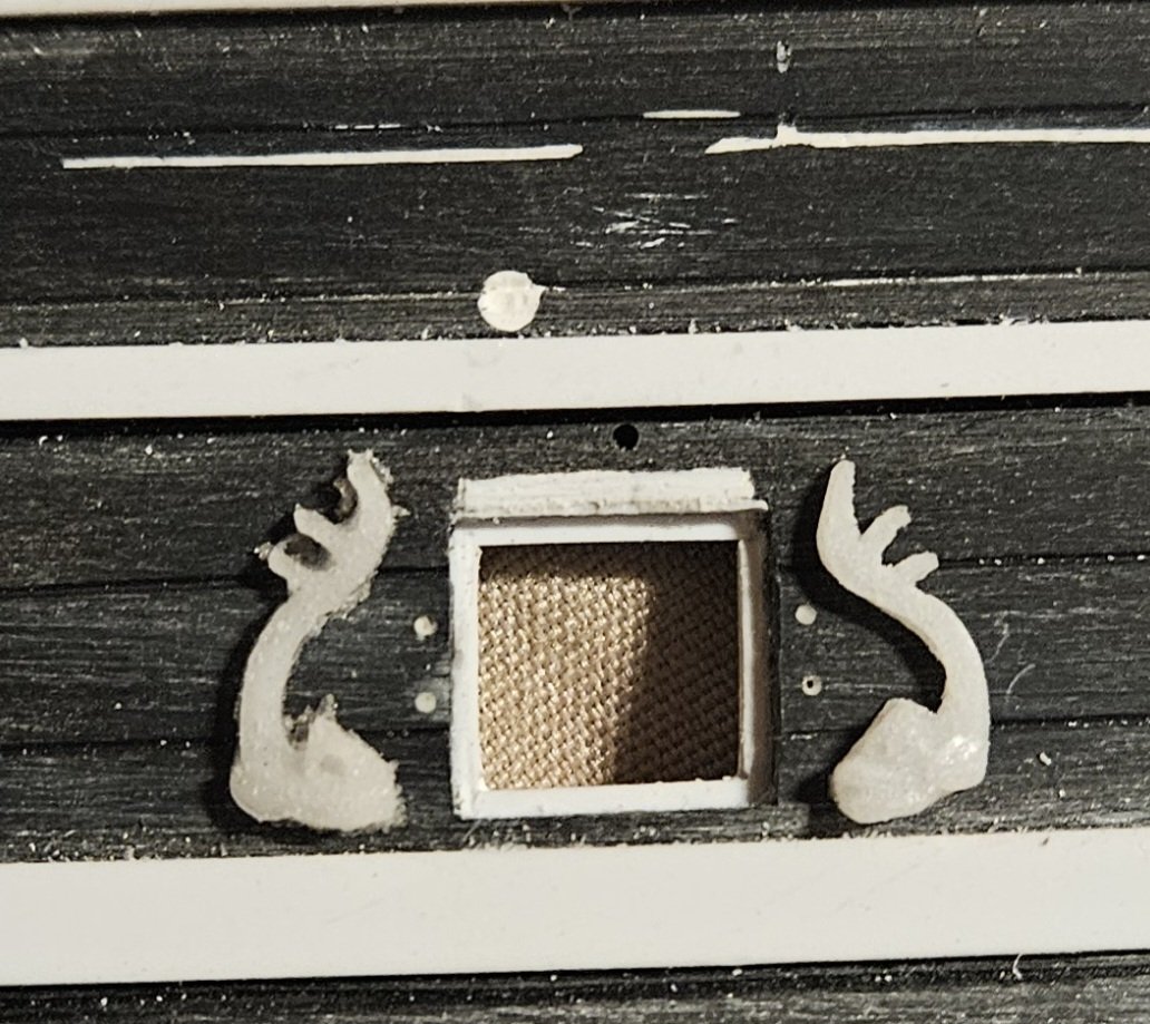
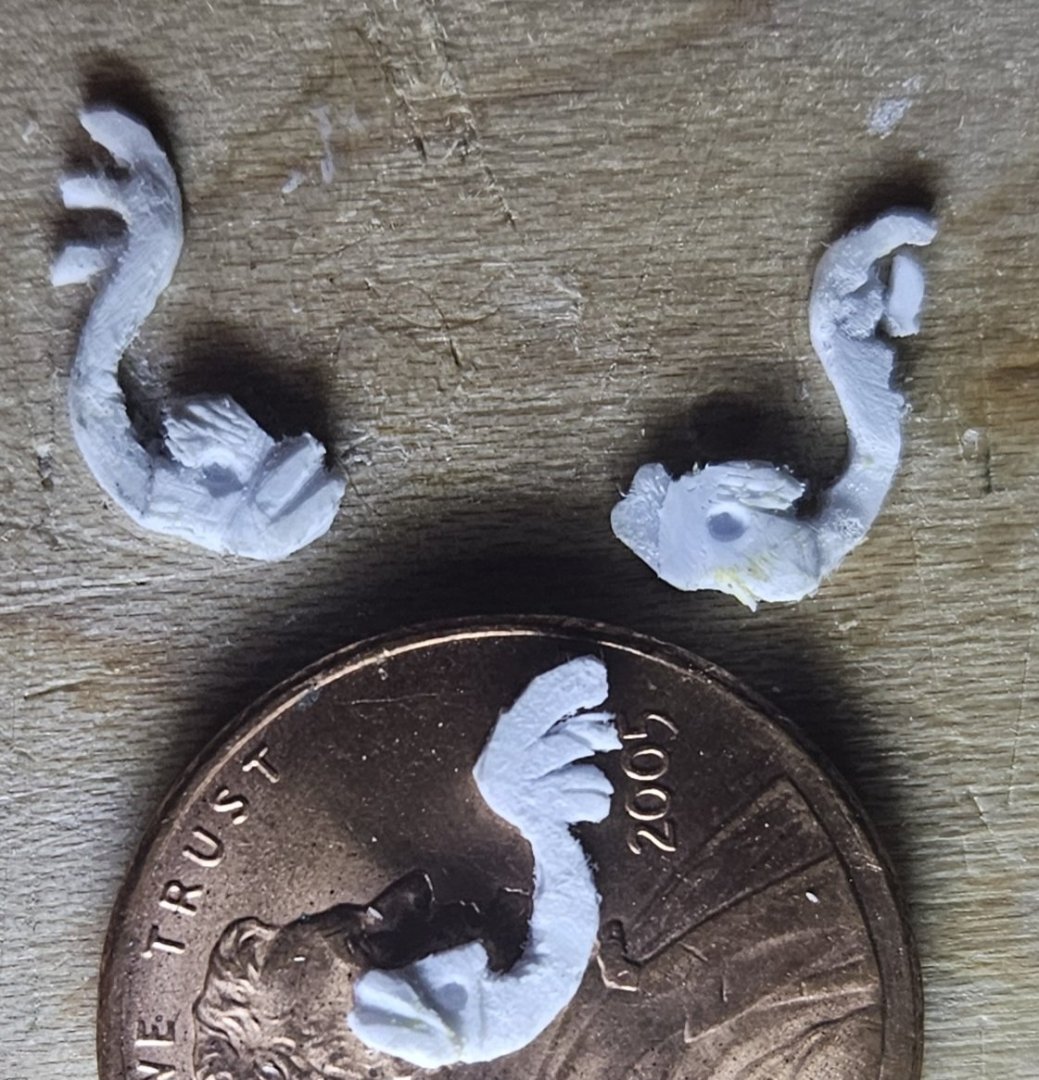
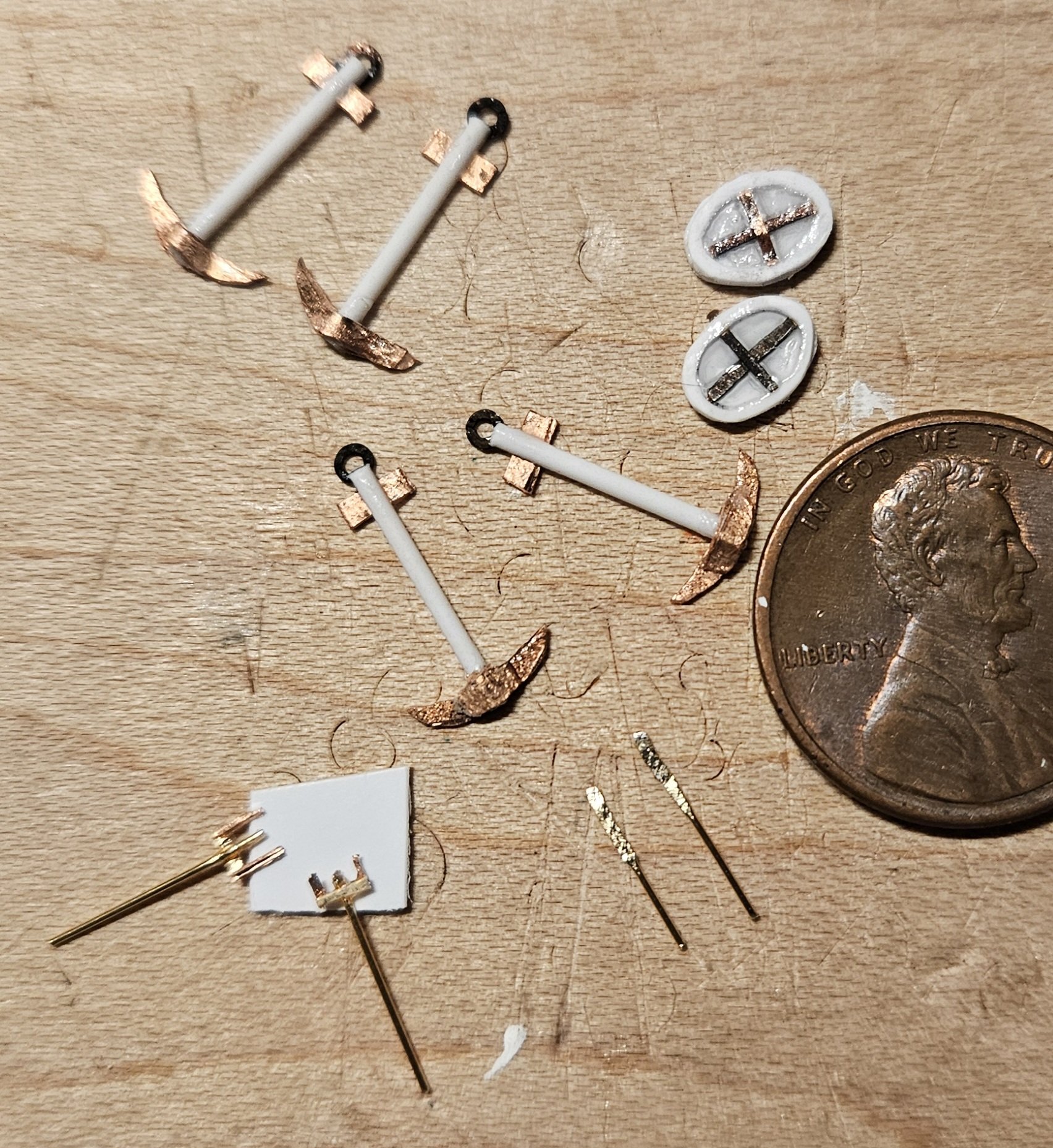
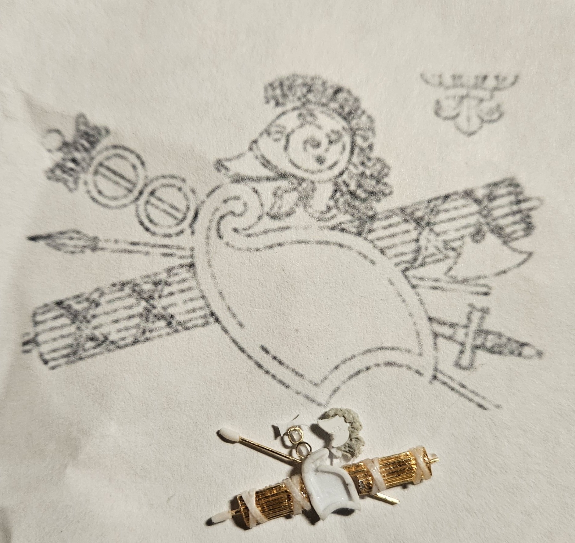
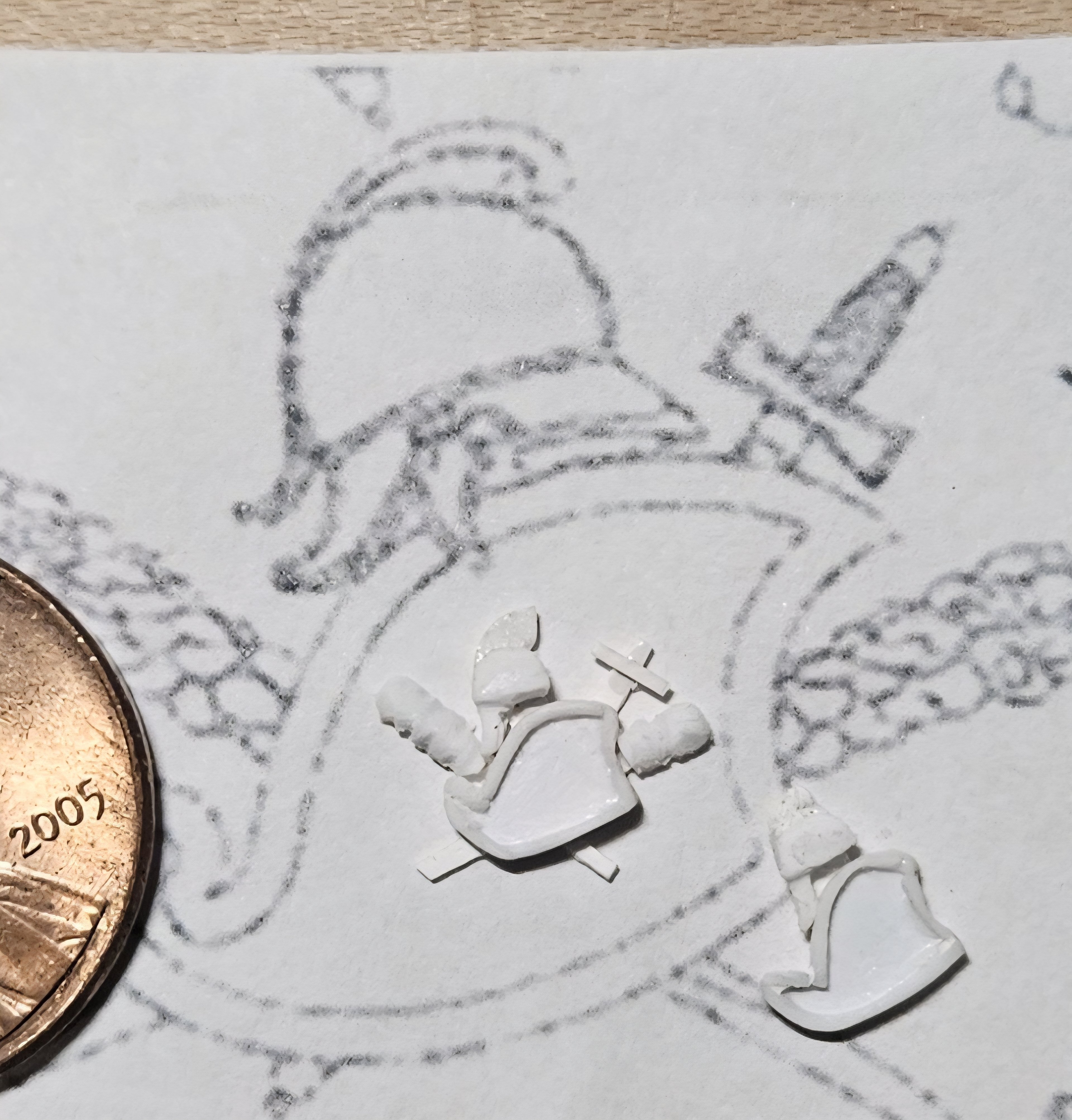
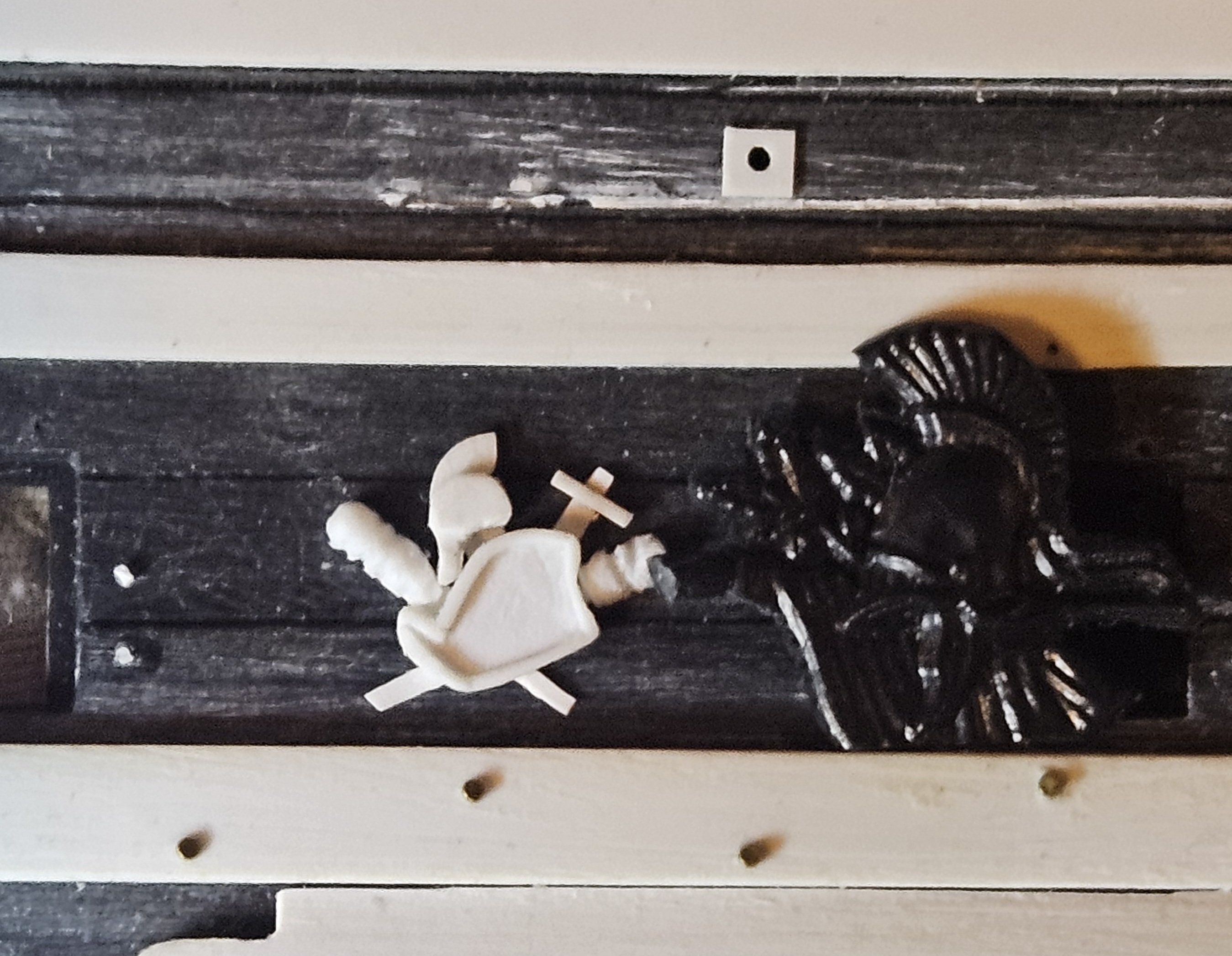
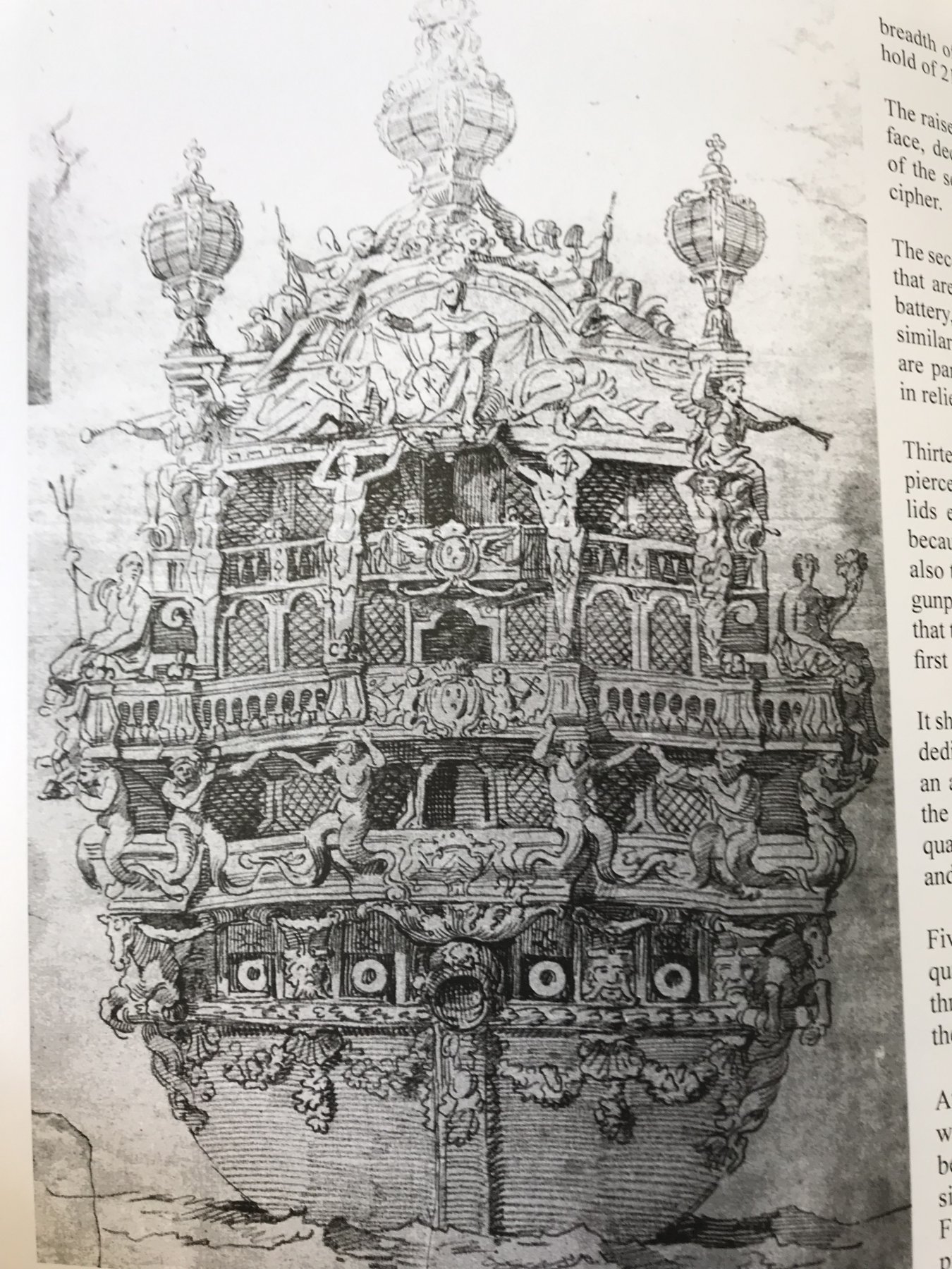
Phew... this 4th Trophy Of War has been the most complicated yet. This is what I ended up with, and paired with the drawing that I was trying to emulate. Without a doubt, wrapping the "rope" around the anchors was the most difficult part of this exercise! I still have to add a tiny piece of rope to the upper left anchor eyelet, but I want the glue bonds to dry thoroughly first. I continued my extensive use of copper wire, tapping different guage sizes into flat sheets to make the flukes, the decorative bands on the shield, the fletching of the spear, etc. I am finding that in some situations, using copper wire is easier/faster than using Evergreen sheet or ApoxieSculpt. For example, several light taps on 28 guage copper wire made a plausible fletching on a spear. I manufactured all of the component parts for both TOW before assembling both together at the same time. My other TOWs followed a predicatable pattern... make the first set and then decide I can do better. I will NOT make this set over... I can live with this! And a parting shot from normal viewing distance.... yeah, I can live with this first effort.


- 432 replies
-
- 8
-
-

-
- soleil royal
- Heller
- (and 1 more)
-
Finished with the third set of Trophies Of War... with the days being so long and with plenty of yardwork - and boating ! - to do, time in the shipyard is limited to 1-2 hours in the morning. The third TOW is a frontal view of a plumed helmet bracketed by spears and axes.... I can see flaws at a very close range, but I am not going to change a thing, as I think the appearance from normal viewing range is just fine. I MAY trim the axed blade on the right so it has a point on the back side, but then... maybe not. I made extensive use of 28 guage copper wire to make the spears and axes. I just tapped on the wire with a small hammer on concrete to make "leaf" blades on the spear tips, as all that I needed at normal viewing distance was the hint of a point. As for the axes, I just cut tiny blades and straps from the flattened copper wire. This TOW uses polystyrene, copper wire, ApoxieSculpt, and Gorilla Glue. The actual assembly took only two hours, but I had to build in plenty of drying time.


- 432 replies
-
- 5
-
-
-
- soleil royal
- Heller
- (and 1 more)
-
Back to work on Trophies Of War after 10 day hiatus due to a Canadian fly-in fishing trip, etc. With all of the gear in the basement that needs unpacking... my attention strayed to the ship to finish my second set of TOW (2nd set of 12). As I contruct each set, I am attempting different techniques/materials, which will hopefully help in the future. This is the TOW I was trying to create... And I completed two of these after having a redo on the helmets that I made before my trip.. You can see the extensive use of 28 guage copper wire... I stretched a two foot length of the 28 guage wire by hanging a weight on one end, which resulted in a very straight piece. I cut the rings on the staff from 1.5mm brass tube. The plume on the hemlet is AppoxieSculpt clay as I was experimenting to see if I could get a bit more texture. The shiny amber blob on the helmet is a tiny dab of Gorilla Glue; I couldn't figure out to make the helmet a bit more three dimensional by giving it a dome shaped quality. My "super glues" were either too thick or too thin to reliably form and hold a dome shape before trying, but Gorilla Glue seemed just right and resulted in a very symmetrical dome shape, especially viewed from the side (the tiny air bubbles are not pock marking the surface, but are buried in the blob and won't be visible after painting. Finally, instead of making the helmet from 0.13mm thick styrene, I beefed it up to 1mm thick and then added additional pieces for the protective visor and cheekpiece in an attempt to make the helmet have areas with varying thickness to hopefully create some shadows, as it is the centerpiece of the assembly. Of course, I am not satisfied with the original helmets that I made! (these are very simple helmets with no plumes, so they should be easy to remake). However, I am a bit burned out on helmets and need to try a "one off" TOW that has a different shape (with NO helmets)... the weaponry will be very easy to make from 28 guage copper wire.


.jpg.31f5b03ebeb0ce42d85384687e9afbdc.jpg)


- 432 replies
-
- 6
-
-
-
- soleil royal
- Heller
- (and 1 more)
-
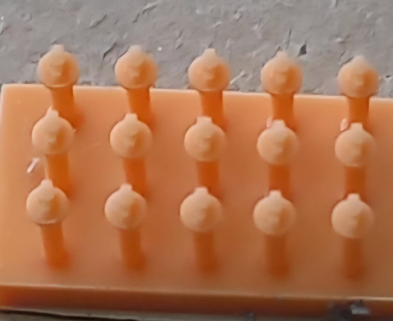
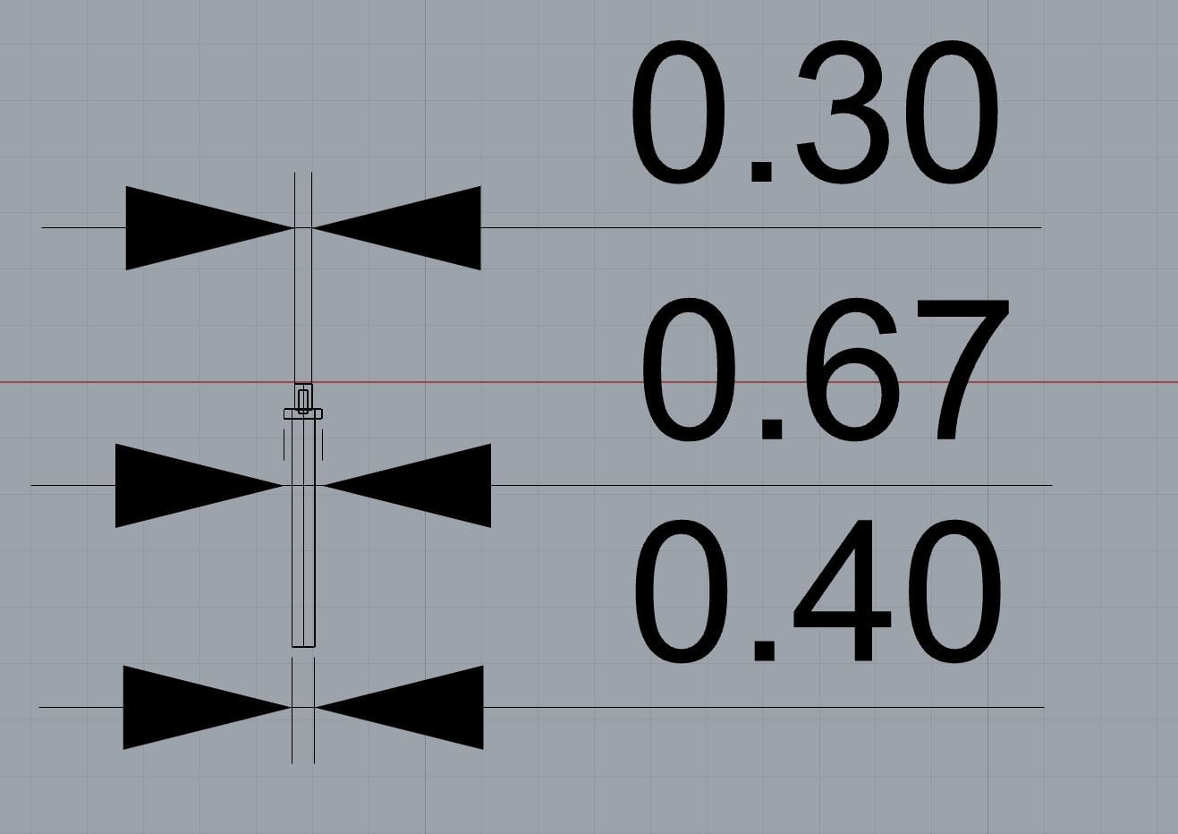
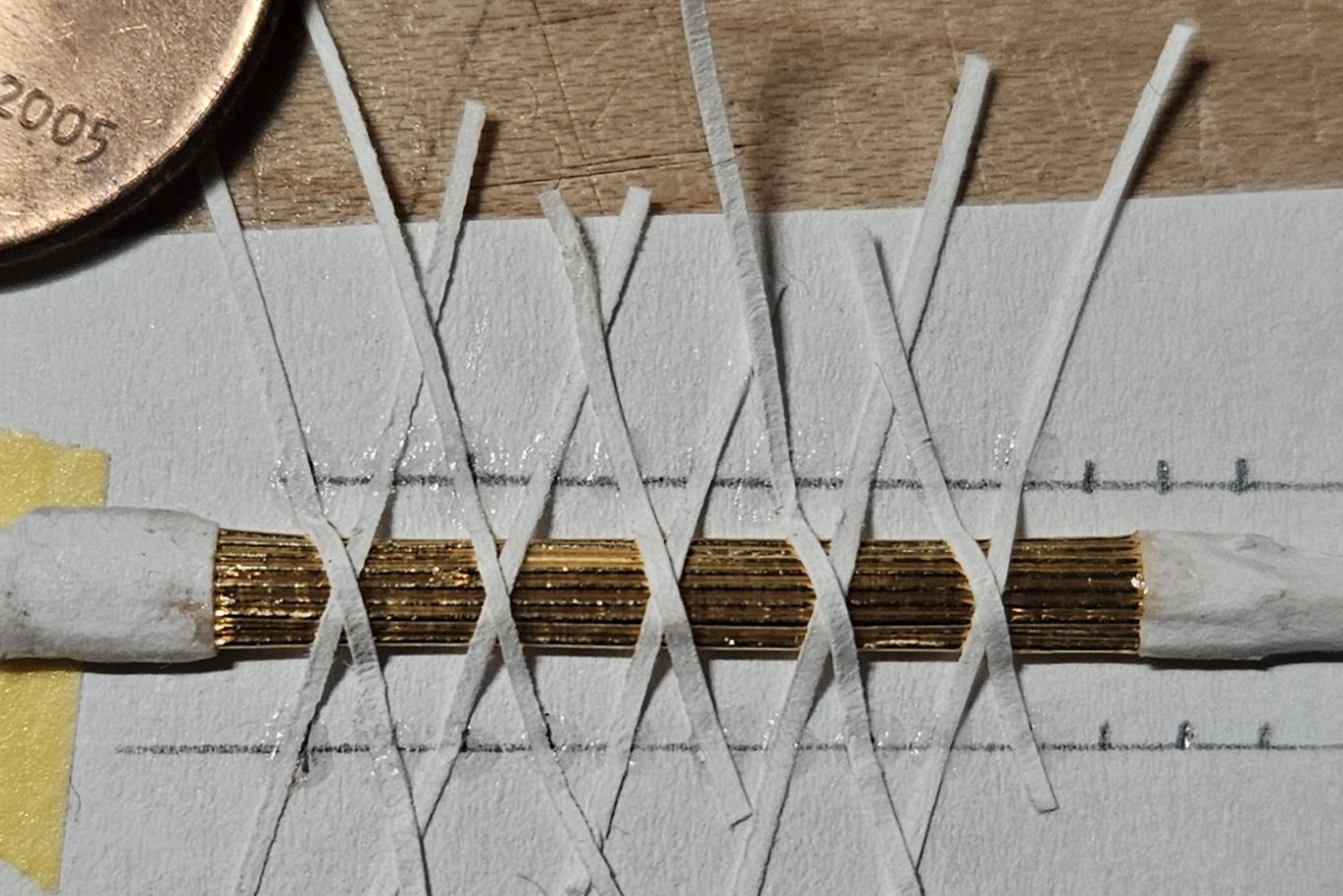
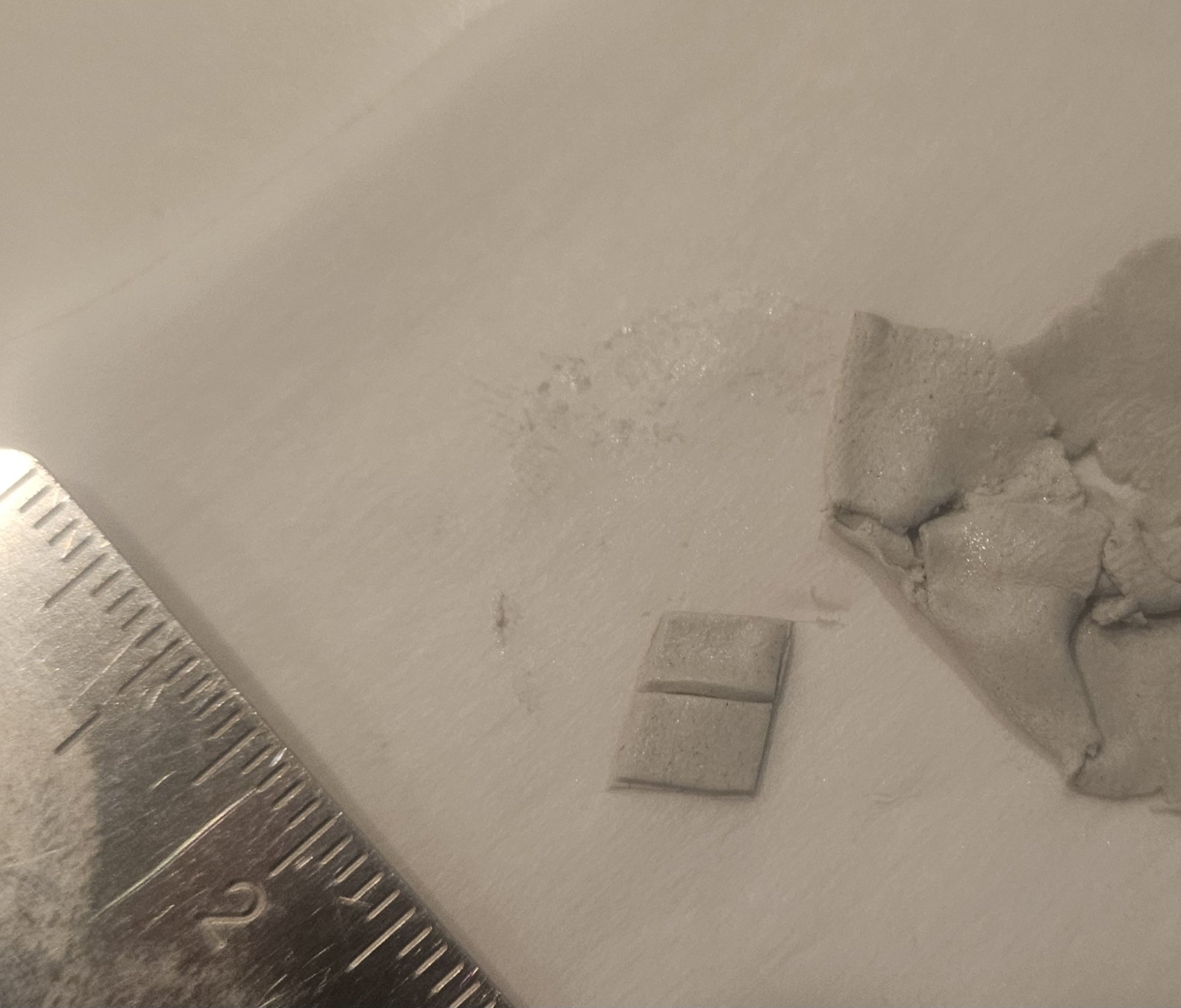
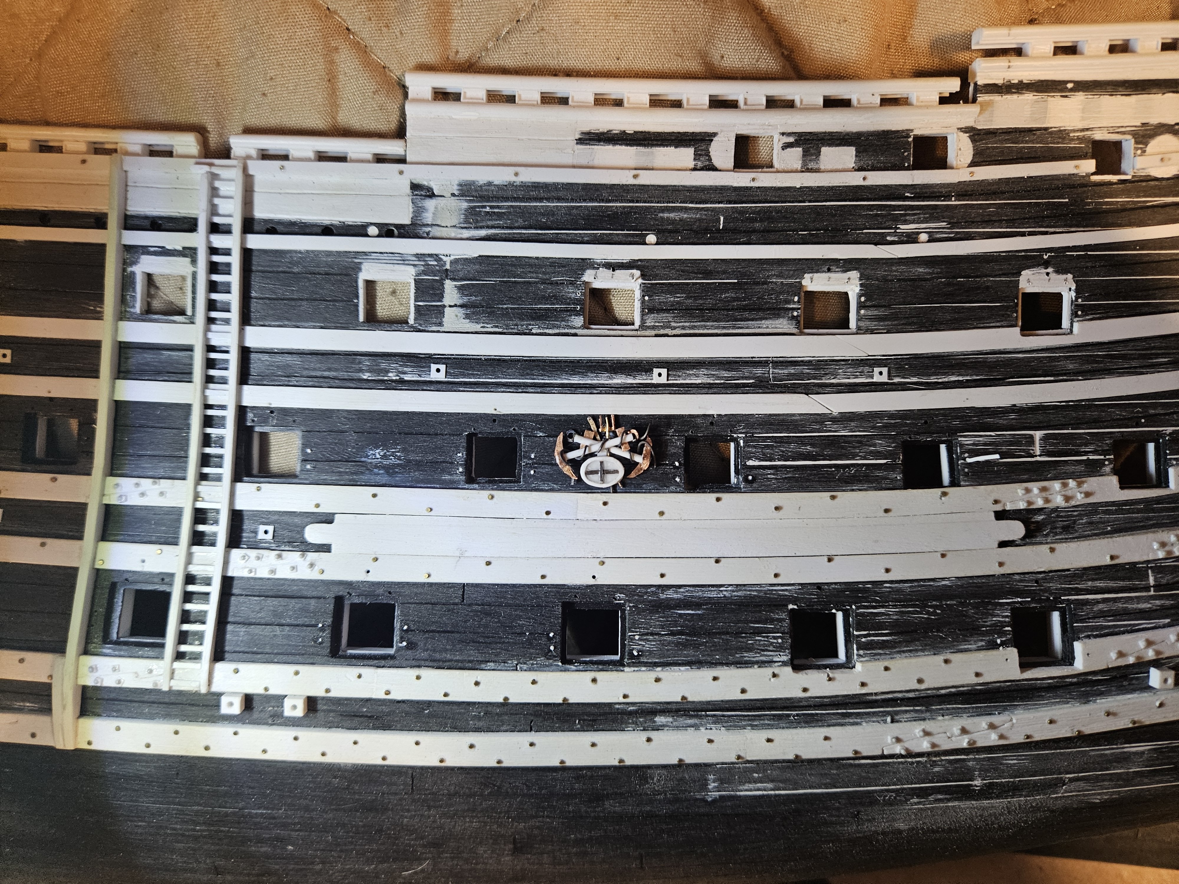
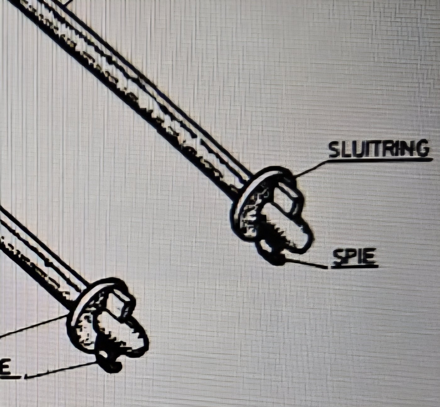
I have become intrigued with the concept of "how small can things be accurately made..?"... for example, observing what Marc LaGuardia (Hubac's Historian) has accomplished on his build, as well as sources like Phillip Reed's books/videos.. So on to my second set of twelve total sets of trophies of war.... I had speculated that I would be done with all twelve sets in "10-12 days..."... ummmmm, not going to happen. OK... I see the helmet is plain (I used Apoxie Sculpt to make the plume), and my spear points aren't pointy and half a dozen other flaws. However, when I remind myself that you can only add so much detail at this 1/100 scale, and that this is the view that people are going to see.... I can live with this and move on to the next. And you may note I ;eft off an axe head and the handle of a sword; I left them off as it madeit even more cluttered - and I figured the ridged detail of the quiver would attract the eye, anyway.... I made the rolled up quiver a bit longer, as I wanted the eye to be drawn to the quiver. I glued 25mm lengths of 28 guage copper wire onto a 1.5mm half rod. And as Clint Eastwood observed.. "a man's got to know his limitations..", I knew that I couldn't apply the cross straps freehand. I had to make a jig to guide my pattern. And after dousing the paper strips in thin set cyano, I ended up with a blank to cut my 4 pieces from to make two trophies of war. Then it was just a question of making the other parts of the trophy. I am just going to leave well enough alone and move on to the third set! Regarding how small can you accurately represent things? For some reason, I really got hung up on making a tiny gun tackle rod/washer on the outside of the hull, per this Dutch drawing that shows how a wedge was hammered in to hold things in place. However... I knew my limitations and no way could I attempt to make 400+ of these!!! Until I went back to Nigel's Soleil Royal build, and remembered he had ordered some beautiful cannon and gun carriages from Kris at Skutznik (Poland) who did 3D resin printing. So I contacted Kris... and am getting 110 cannon and 36 gun carriages (I will only use these carriages on the upper decks where they will be visible)! The cannon will be bore size and length appropriate, thus saving me weeks of time working on the kit pices to "beef" them up. But then I had a thought.. how small can pieces be made? Could Kris make the gun tackle rod/washer/wedge at a tiny, tiny scale? He said that he would give it a try, and a week later.... I have ordered 500 total pieces from him! The washer is all of 0.026" in diameter, and the rod is only 0.011" in diameter. At normal viewing distance, you can just make out the wedge. I was already drilling 4 holes at every gun port to put my tiny copper nails in, where the round head would simulate the washer, and I was going to stop there. But instead of inserting nails in the holes, I will simply insert these pieces and have a rod/washer AND a wedge!


- 432 replies
-
- 7
-
-
-
- soleil royal
- Heller
- (and 1 more)
-
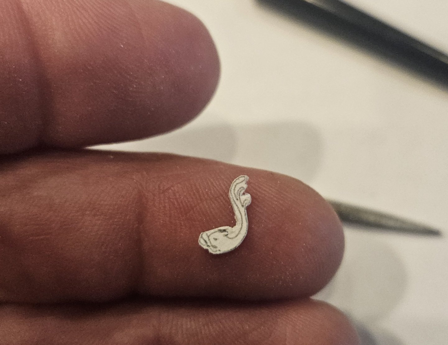
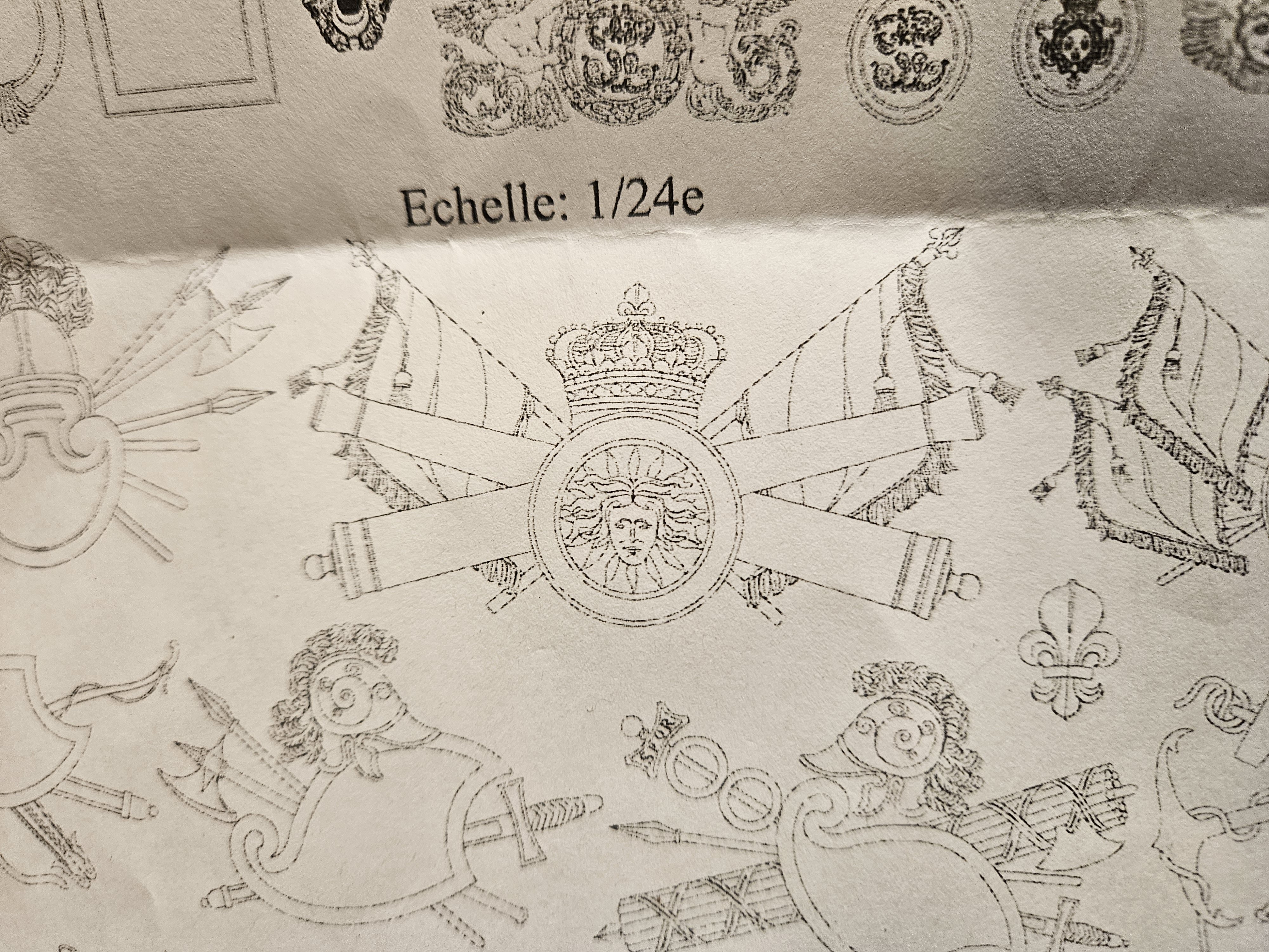
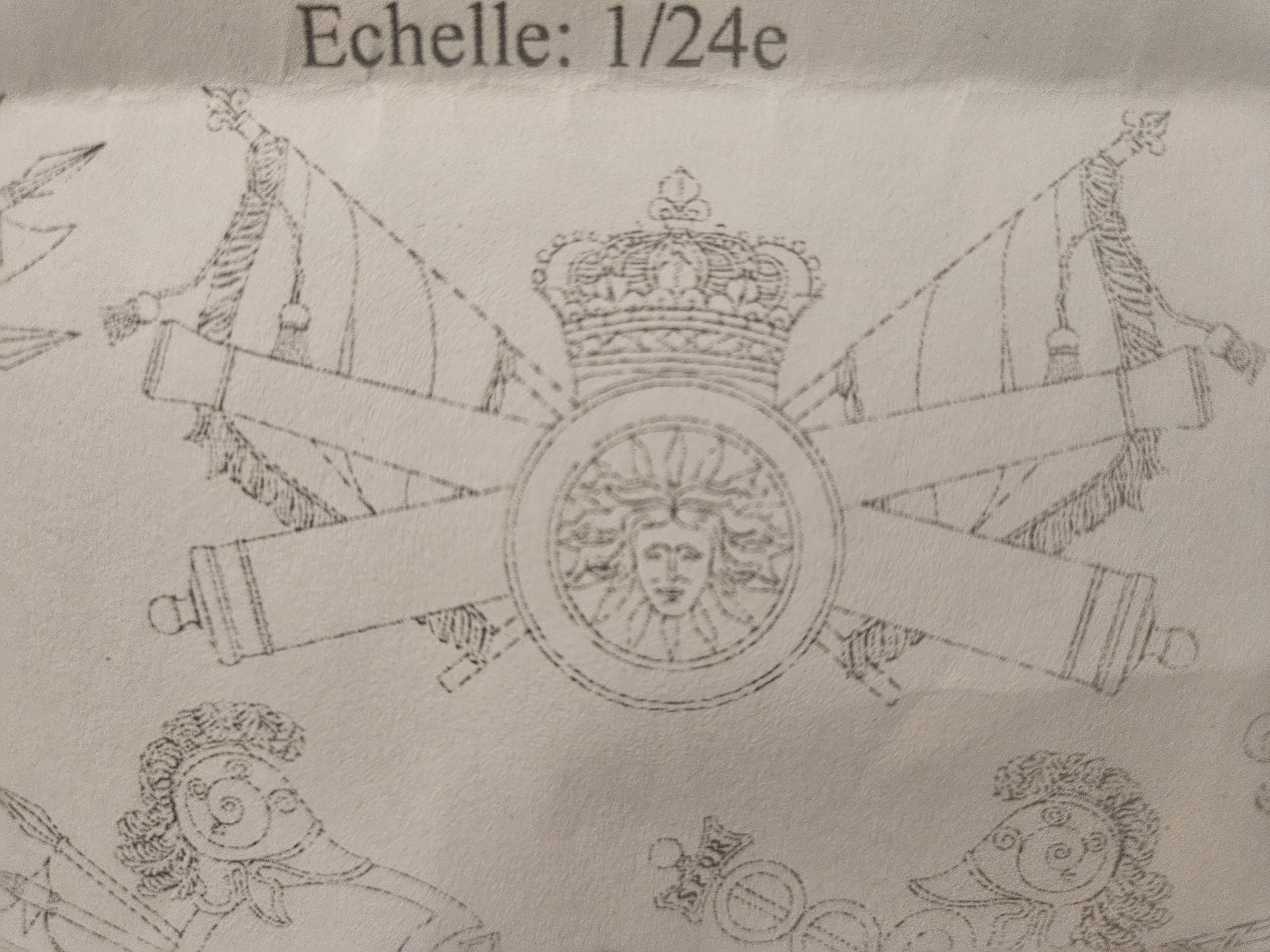
I am starting to carve my trophies of war that will be displayed between the middle gun deck ports. There are twelve "trophies" on the St. Philippe monograph, and conveniently, I have twelve spots that need filling... twelve trophies, two copies of each (and since they will be displayed on different sides of the ship, I don't have to agonize over making them identical as I had to do with the dolphin carvings. Here is the end result of my first trophy of war pattern (there are some tiny corrections to make, but honestly they will be very difficult to observe at a normal viewing distance). Conveniently, the ship kit has six trophies of war featured on the quarter, but as shown below, they are just too big for me to use... It required about two hours of time to make the first two copies; I chose the easiest pattern to start! First, I had to settle on the appropriate size of the St. Philippe trophies so the tiny photocopies could be glued to styrene sheet. Conveniently, five of the twelve trophies use an identical shield, so my first step was to make ten shields (five face right, and the other five face left). The next step was to carve out a tiny helmet - my small wood gouges really helped with the curves here. And this is what the first trophy looks like overlaid on the 1:24 size copy. There is a tiny bit of cleanup work, but it will be very hard to see at normal viewing distance; I exaggerated the size of the crest on the helmet so that it could be seen. I even tried to make the protective cheek and ear flaps for the helmet, but they were so small and hard to see, I decided that step wasn't worth it. Now on to the second set of trophies; this will probably take 10-14 days to finish, but it will be worth it.


- 432 replies
-
- 6
-
-
-
- soleil royal
- Heller
- (and 1 more)
-
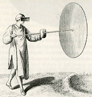
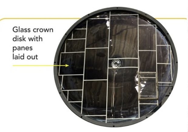
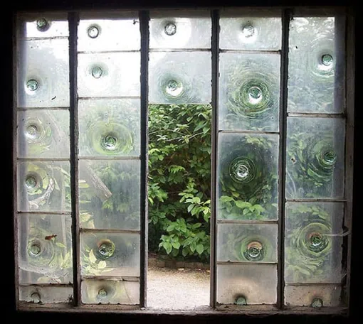
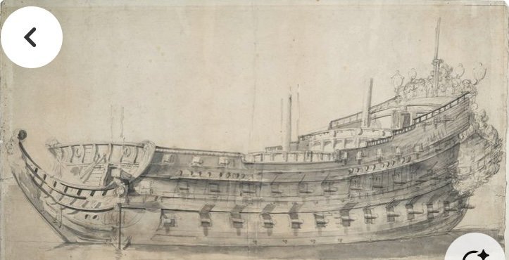
Sigh...on vacation for the last week, so no manual work on the ship. However, that early AM time with a cup or two of coffee AND before others are awake is a great time to think and ponder. And one of those ideas for me is ..."before 1688, ship windows consisted of small, diamond shaped pieces, and not larger rectangular or square windows". As seen below in a 1668 drawing of Royal Louis... As I am trying to construct a plausible 1671 Soleil Royal, this idea is important for me. Some alternative design choices I have made, for example 1) a long, low Dutchy head, or 2) the lack of gangways are due to what I believe is the Dutch training and/or school of thought that Laurent Hubac emerged from. But the idea that windows were small, diamond shaped pieces of glass... that is resource driven and NOT a design choice. If I were Marc LaGuardia, or John Ott, for example, I would launch into a doctoral worthy dissertation that is both entertaining and informative... "Window glass making has been around since the Roman Empire, but the glass pieces were thick, small, amd discolored. But they allowed some modicum of light in, whilst keeping the bugs out. And that was the extent of it for a millenia or two! And then, the mouth-blown cylinder technique for making (somewhat) flat glass was developed in Germany sometime in the 11th century. This glass was called Broad Glass. The glass was blown into a balloon, but elongated enough that it resembled a cylinder (note that true Cylinder Glass developed centuries later). This cylinder was cut by shears while still hot and then flattened on an iron table. Finally! Relatively flat glass could be produced, but... the but was the quality was poor and had many imperfections and was fairly opaque... but, it was getting flatter. And then another mouth-blown technique was developed that the French perfected in the 14th century.. and they enjoyed a monopoly on this product for a century or two! The technique was called Crown Glass. A blob of glass was blown into and then spun, with centrifugal force making a disc perhaps 3 feet in diameter. However, the best glass was in the thin areas on the outside of the disc. The pictire below demonstrates the odd cuts that had to be made in order to get the best, thinnest glass on the edges. So if a large quantity of quality glass was required, small shapes from the edges of multiple discs had to be painstakingly assembled... the small, regular diamond shape was born. Not because of a design choice, but because of nessecity. In 1688, the first technique was perfected - by the French again! - that was NOT mouth-blown and also produced flat, translucent glass. This was called Plate Glass and involved pouring molten glass on a special table. This made a flat sheet, but required much labor intensive polishing on both sides. This glass technique made quality glass but at a price.. so it was relegated to the rich. Or.... the REALLY rich like a king... amd his ships? I find the year 1688 very convenient, as this starts to tie in with the Second Marine ships, and the rebuild of SR 1671...." So there it is. I believe that all those early, magnificent ships... Soleil Royal, Royal Louis, Monarque and so on... they all had windows consisting of small, diamond-shaped pieces of glass. Not by choice, but because that is what they had. So that is what I will do with my interpretation of SR 1671... ohh.. did I say I now just have to figure out a way to create windows from these tiny, 💎 shaped pieces? By the way, the spot where the blowers tube left a mark like a belly button was considered junk fit for peasants. Can you imagine the value of a window like this now?!

- 432 replies
-
- 4
-
-
-
- soleil royal
- Heller
- (and 1 more)
-
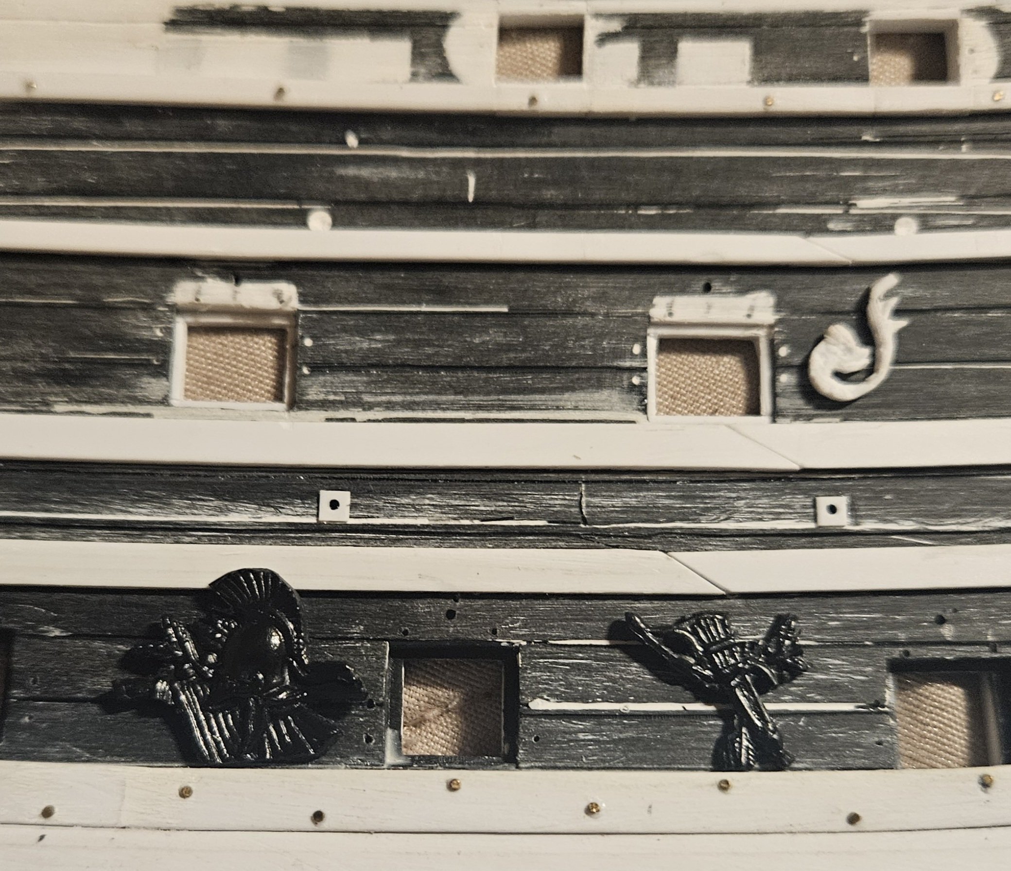
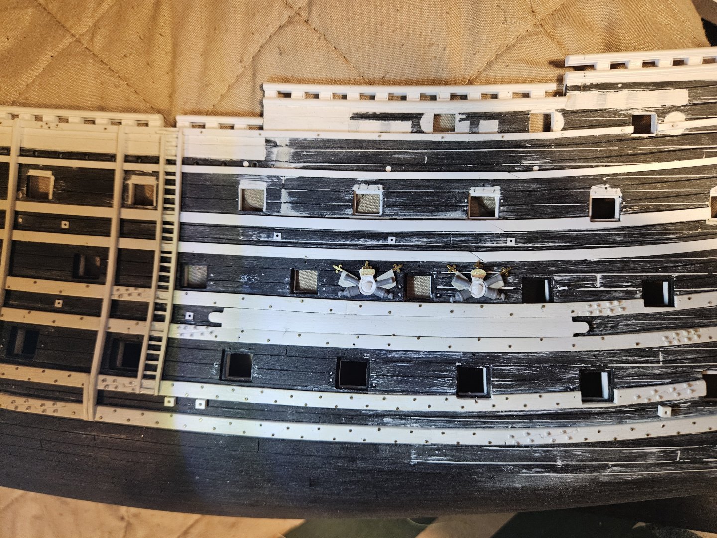
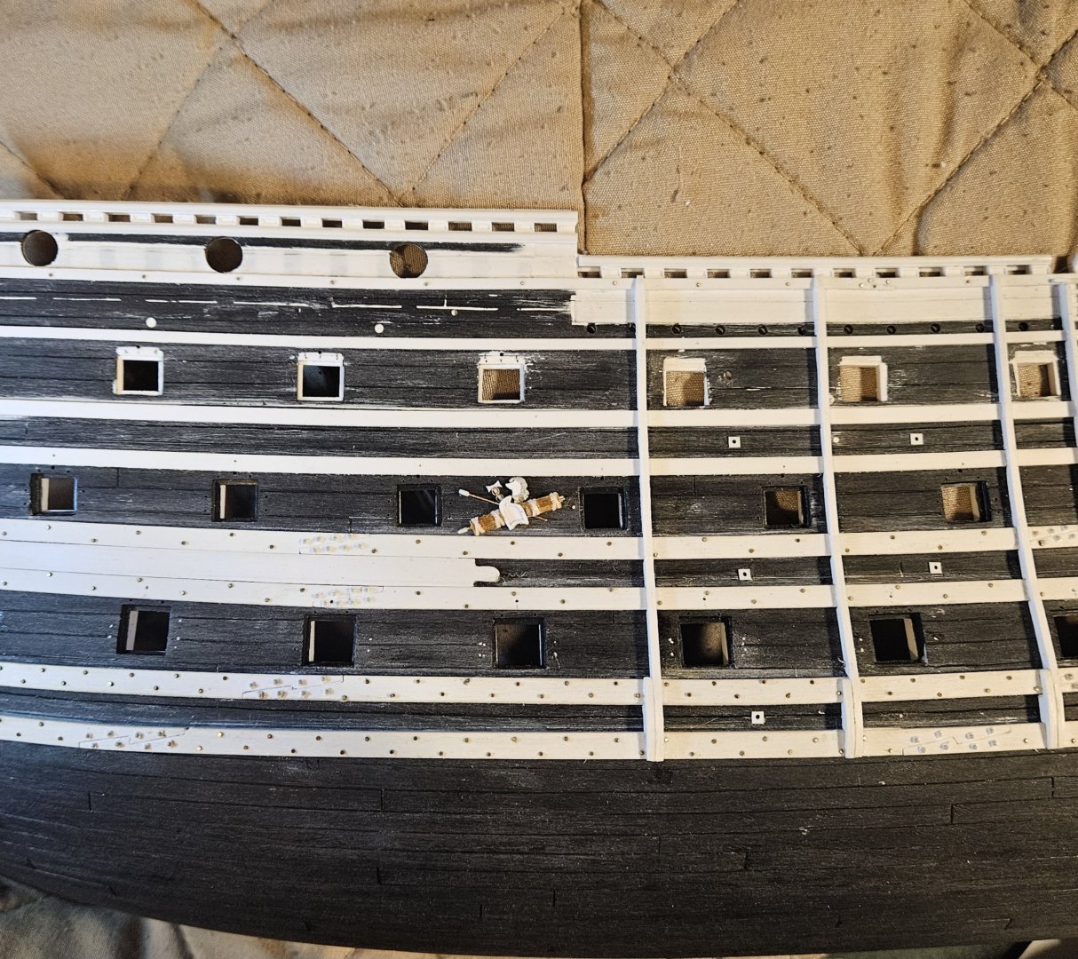
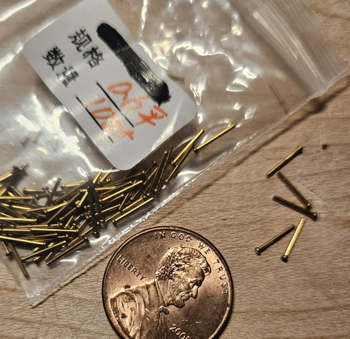
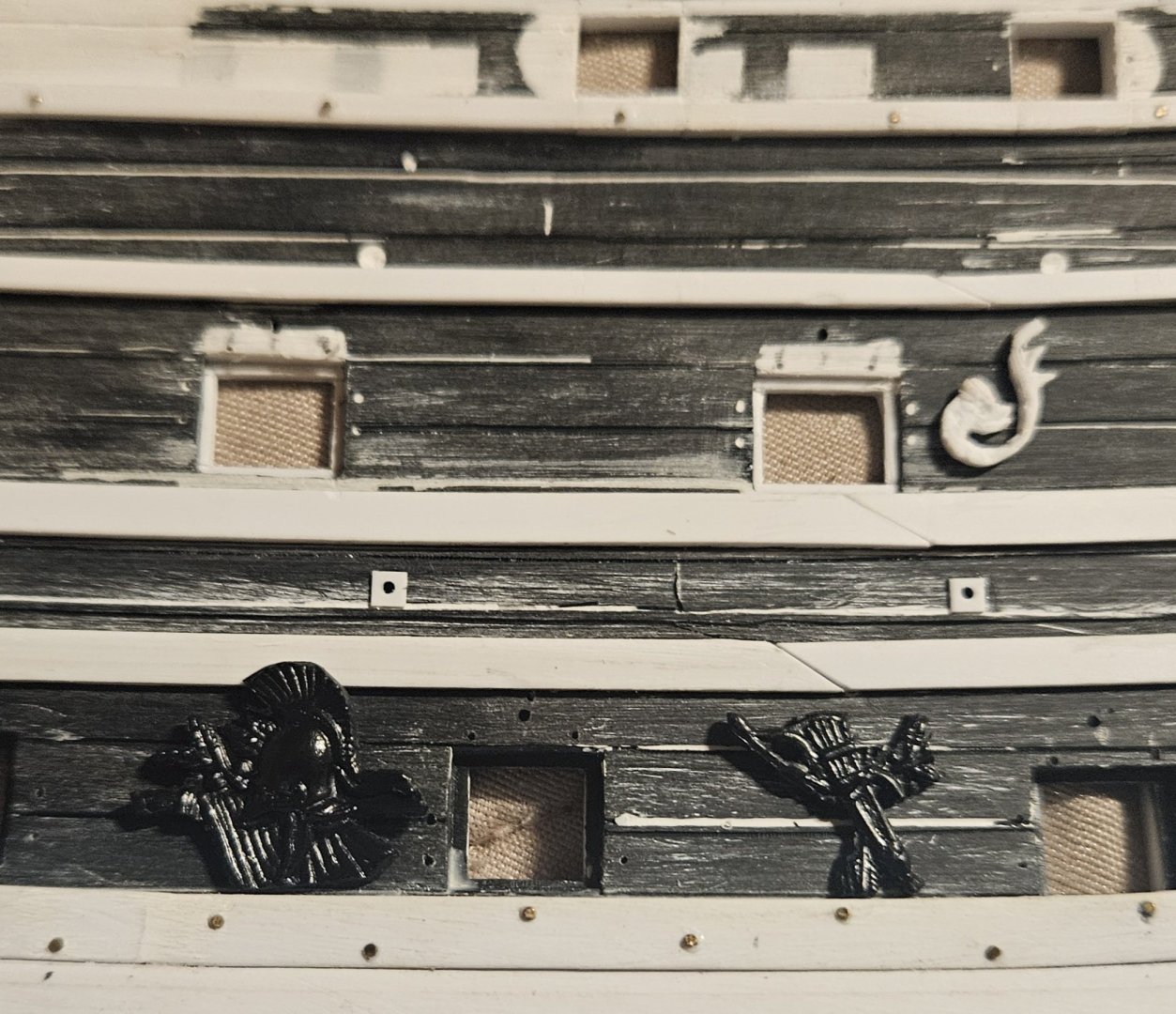
Before I apply any of the decorations, the gun tackle bolts need to be put in place. I have 600 nails that have 0.6mm flat heads; I figured these would look like the large washers on the hull that secure the through. I was originally going to blacken them and install them after the hull painting, but that isn't going to work; they need to be installed now, and it doesn't make sense to blacken them, as a tiny dollop of black paint after hull painting will do the trick. I made several jigs so I could have a precise, repeatable pattern despite the gun port holes being of varying sizes. Using the jigs, I simply drill a hole through the hull, insert the nail, and secure it with a bit of glue. You will note that I plugged my first attempt at a hole pattern (which I did many months ago in an amateurish way). It is going to take some time to make 400 holes or so - and when I get up to the gun ports that are visible on the inside of the ship, I obviously can't drill all of the way through the hull. I will make a shallower hole and snip of most of the length of the nail. The two dolphins haven't been cleaned, and I just laid them in place to get an idea of what they will look like.
- 432 replies
-
- 4
-
-
- soleil royal
- Heller
- (and 1 more)
-
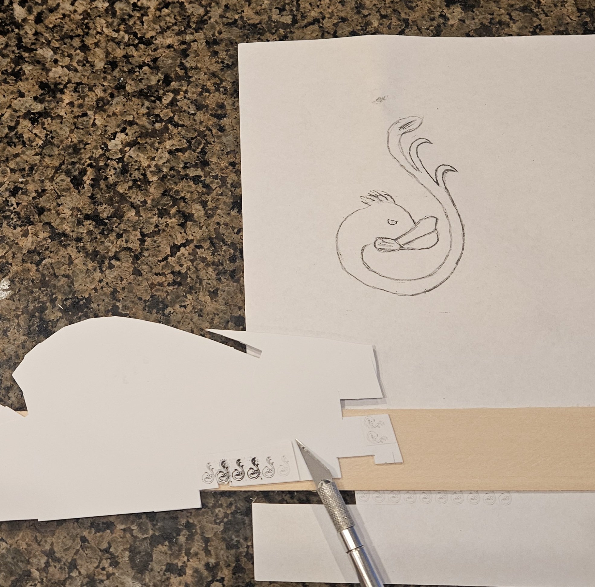
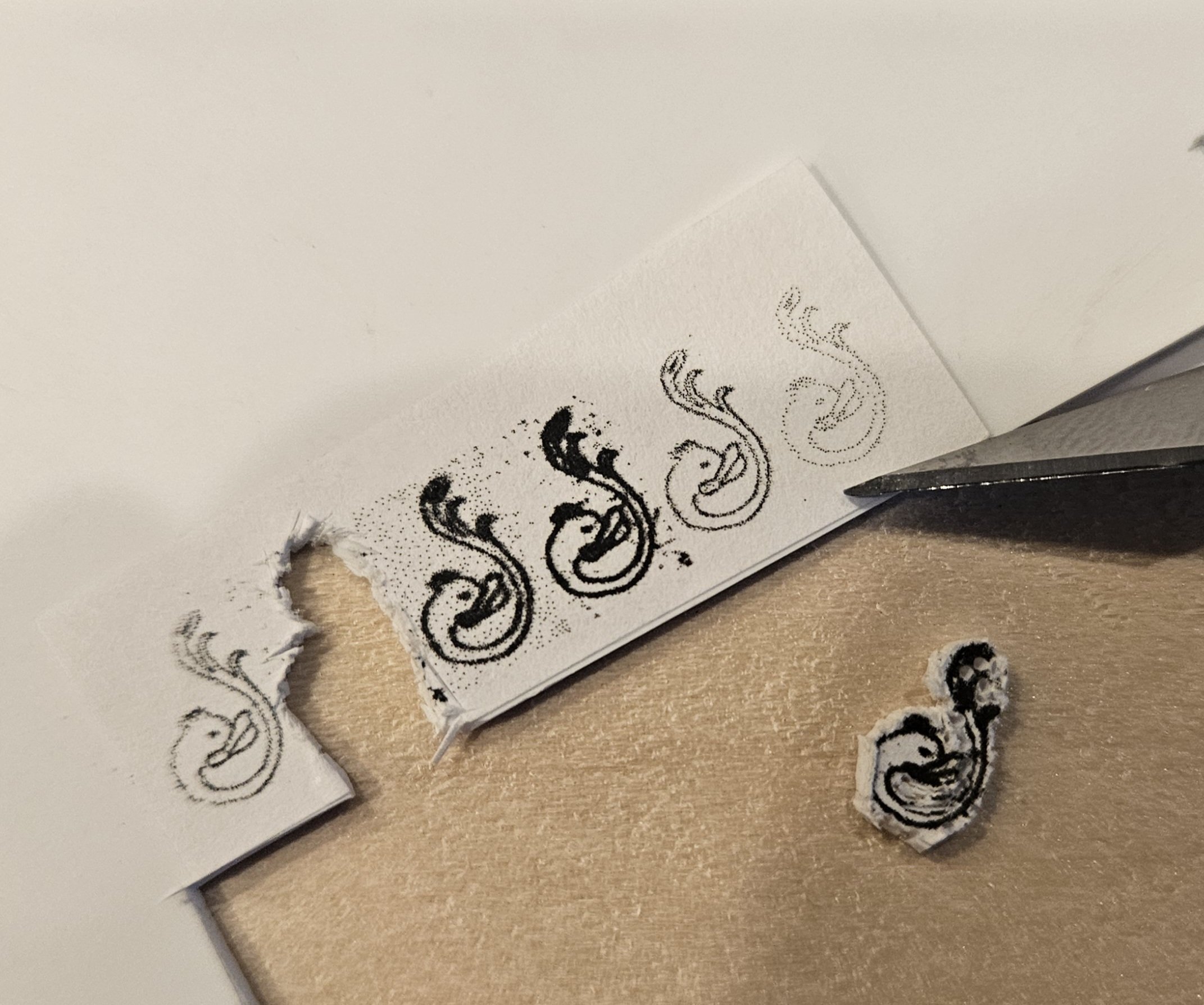
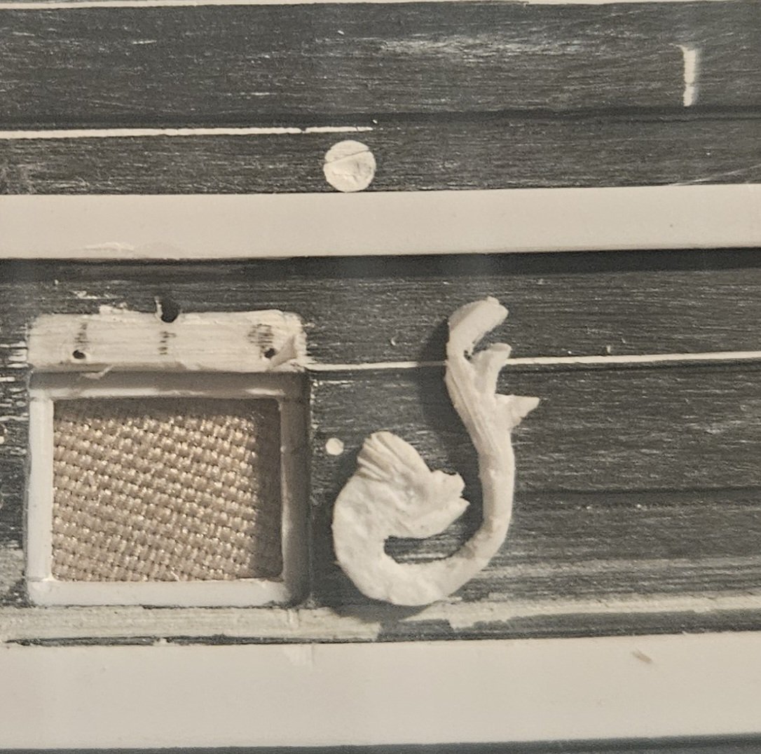
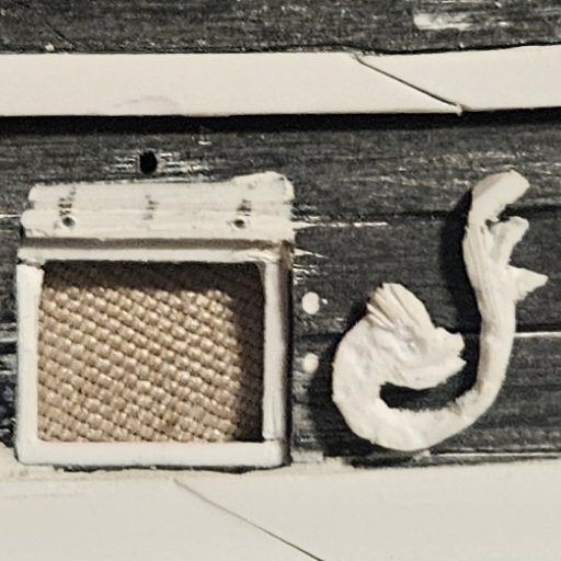
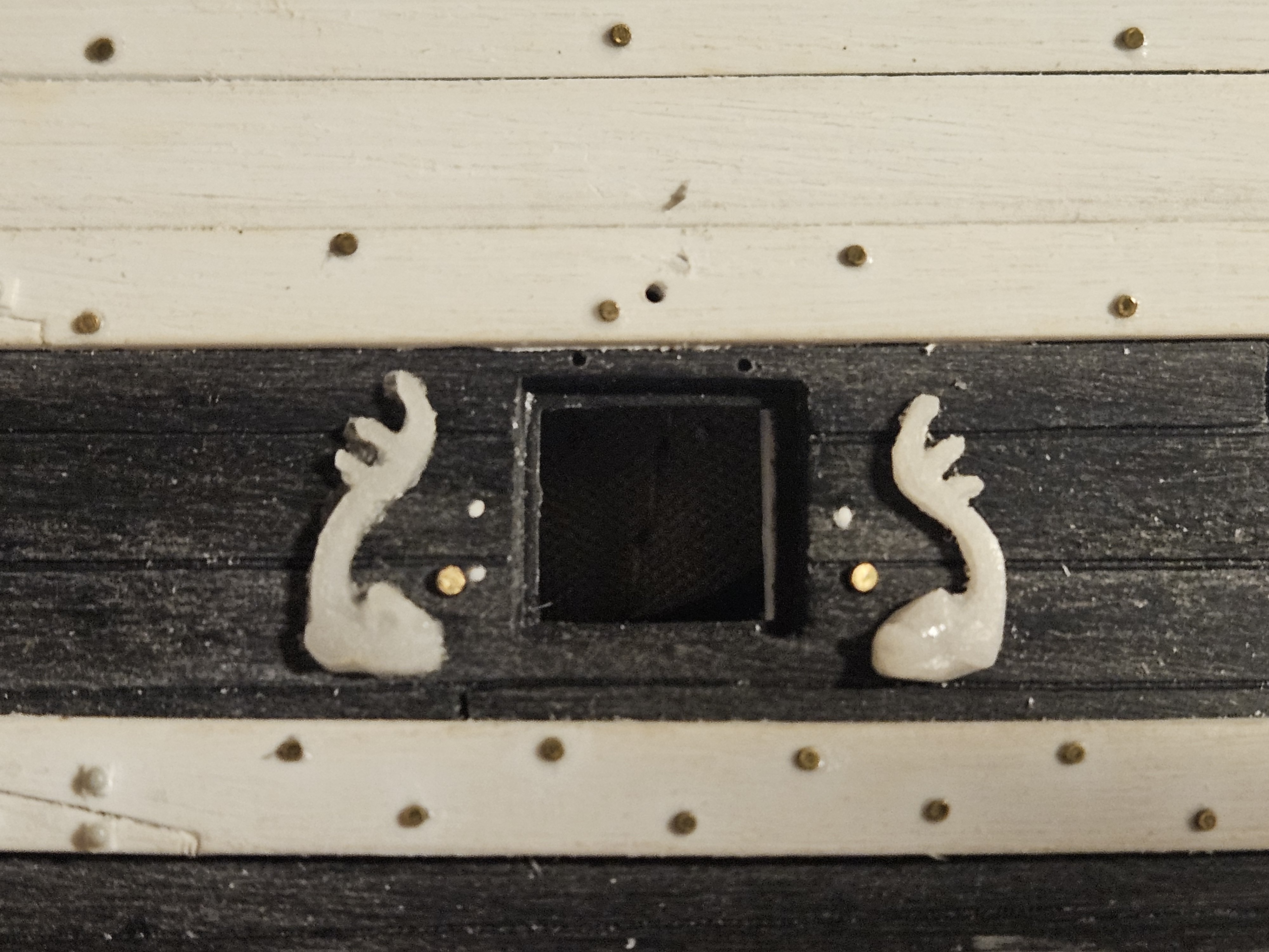
As I have said before, sometimes it is 1 step forward for me... and then 2 steps backwards. Take the dolphins that will bracket the uper deck gun ports. I was very happy with the right hand dolphin that I created from my vellum sketch. I drew the sketch, and then shrank it down to 10mm in size for a template. for the left hand dolphin, I just horizontally flipped the sketch.. but I simply couldn't draw a matching left hand dolphin to my satisfaction! I finally realized that my right hand dolphin, drawn first, had some tiny inconsistencies with the original sketch... so even if my left hand dolphin perfectly followed the sketch template, it wouldn't match. So I photocopied the right hand dolphin, flipped it horizontally, and then used that for my left hand dolphin. Go figure - that approach actually worked. I am happy with this pairing; even though there are some tiny differences (hint, for example, the eyebrows), it is next to impossible to see them at a normal viewing distance. And I am just fine with how the first test casting (they haven't been cleaned up) for the pair looks now... So, that means I am back to cranking out the various castings... I am also experimenting with Marc LaGuardia's suggestion, about having sun castings with the head of the dauphin sprinkled between the fleur de lis on the bulwarks. The kit suns are 10mm in dimater, and as Marc noted, they are just a little too big for scale. a 7-8mm sun seems to be much more appropriate... the sun on the right has the head of the dauphin on it... just a test (also cast from the kit decorations).

- 432 replies
-
- 5
-
-
- soleil royal
- Heller
- (and 1 more)
-
I don't think that I can do any better on the dolphin pair, if only for the reason that the very fine details are lost in the resin casting... and you would need a magnifying glass in hand to get close enough to the master carvings to even see those details. You may notice that the left hand dolphin is getting some dental work (done after I made a test resin casting), as the mouth structure didn't quite match the right hand dolphin. I have a little bit of cleanup work to do, but I won't get carried away. I made these resin castings before I started the mouth surgery on the left hand dolphin, just to see if the were close enough to be twins. These are straight from the casting mould with no cleanup or detailing - I simply wanted to see the Big Picture. I think they are close enough that I can start making a bunch of castings this weekend, and it will likely take several days to clean up the 20+ pairs of dolphins that will be needed to flank the upper gun deck ports. I also have several dozen fluer de lis resin castings, as I mull over exactly how I want to use them on the bulwarks. I am thinking it may be as straightforward as a mass of fleur de lis as seen on the Royal Duc....


- 432 replies
-
- 4
-
-
- soleil royal
- Heller
- (and 1 more)
-
I settled on a dolphin carving that I can live with. The very small curved wood gouges arrived and they did allow me to make very fine curves on the tail fins. However... even in 0.75mm thick styrene sheet, those very fine fins were way too fragile, They broke while unmoulding, they broke while removing the resin casting from the mould, etc. The fins were strong enough at 1.0mm styrene sheet thickness, but that was getting too thick and out of scale for what I wanted. I made the tail section and the fins a little thicker for strength, and now are they strong enough for the moulding and casting process using 0.75mm thick sheet. This is the first resin cast, not cleaned up yet. So now to finish the left hand dolphin, and then I can start making 25 or so sets of dolphins for the upper gun deck gun ports.
.thumb.jpg.1f447561b54e1ac0bfde645bebc9b251.jpg)

- 432 replies
-
- 4
-
-
- soleil royal
- Heller
- (and 1 more)
-
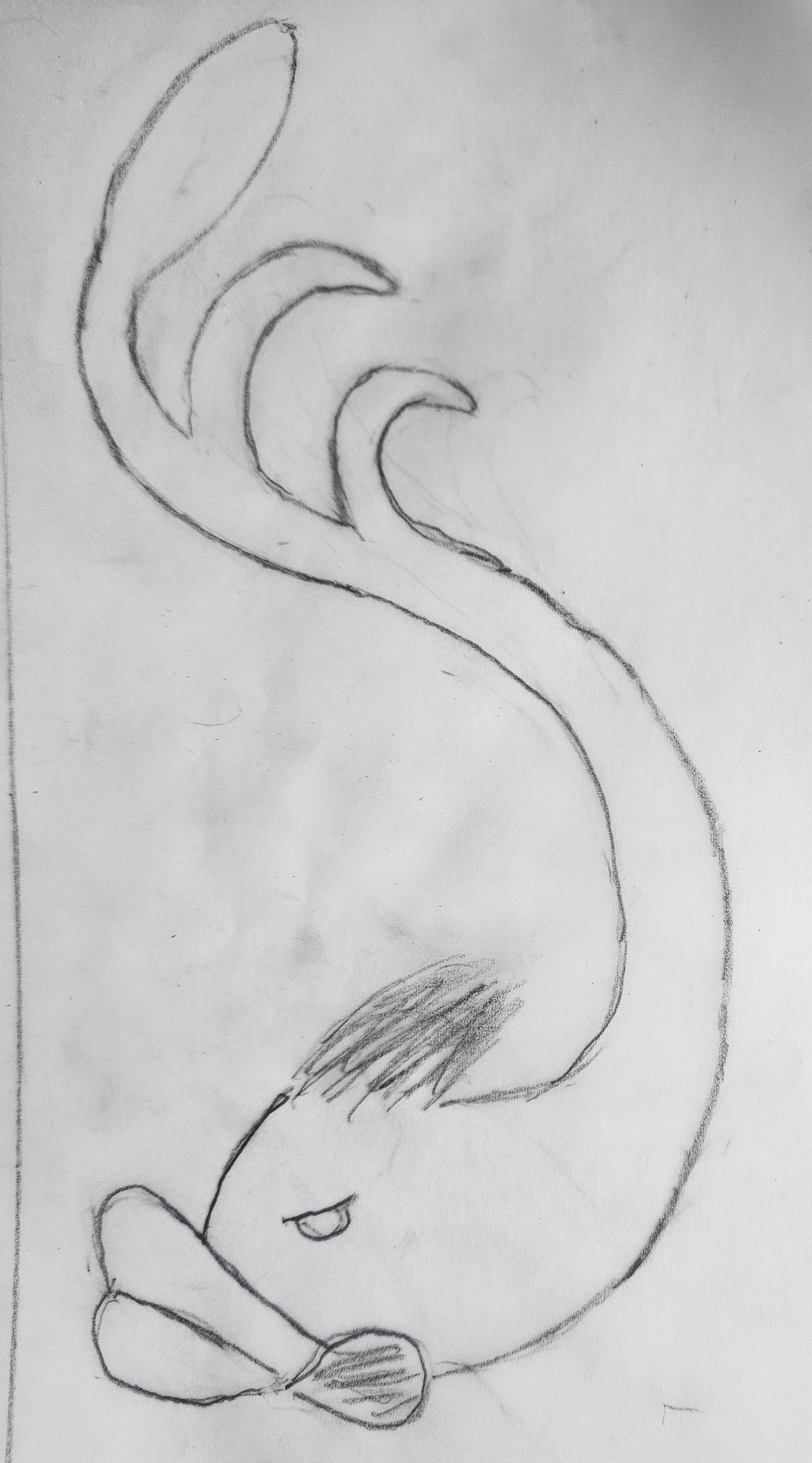
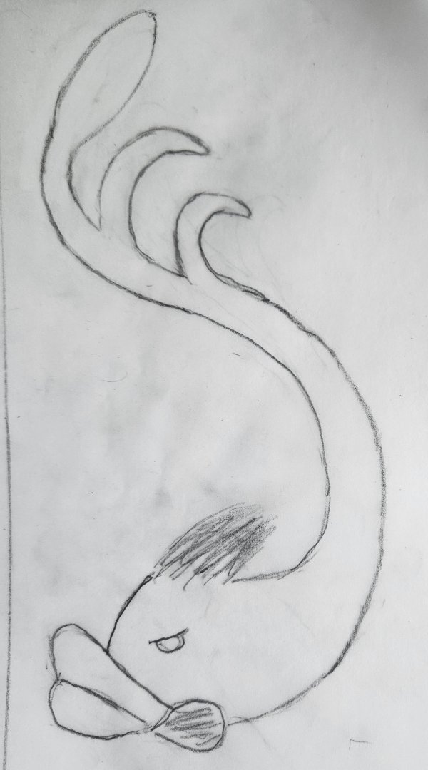
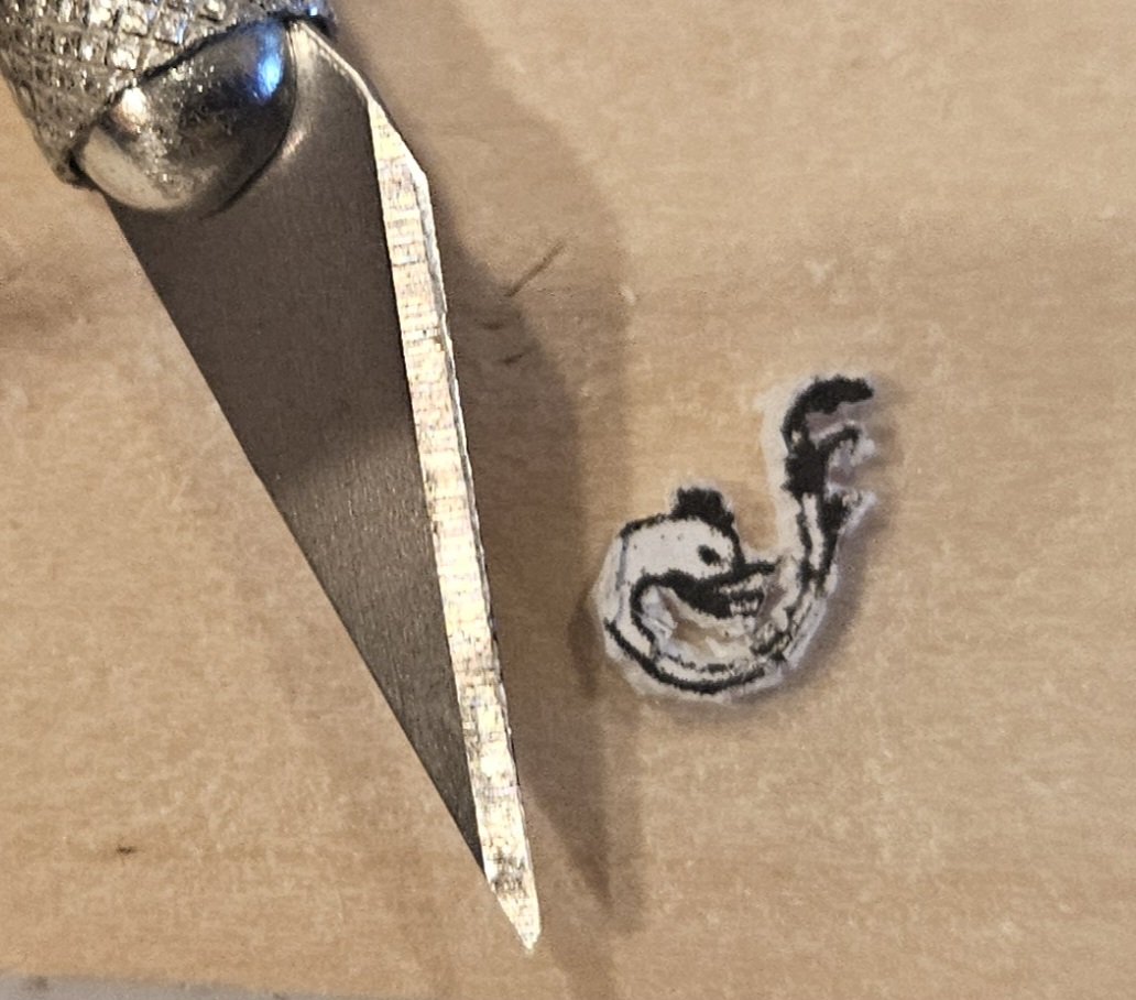
I have patiently carved eleven different dolphins, and I think that the one on the copper penny is just about what I want. The two above the penny were iterations #8 and #9... for some reason, I really liked the look of the carved wooden furniture dolphin below, specifically the big lips! The dolphin on the penny needs some clean up work; I was very frustrated at my ability to make nice, thin, sweeping curves of the tail fins - see iterations #8 and #9! However, I discovered that a very small woodworking gouge that has a shallow curve could allow me to do a much better job than with my #11 Xacto blade. I currently have a 4mm wide shallow curve gouge, and I am patiently waiting for the delivery of several smaller gouges: 1.5mm, 2mm, and 3mm. I know that will allow me to finish off the tail with nice, long fins as I visualized in my drawing, and also thin the body. I also want to add texture on the head ala the "mane" on my drawing and where the small pectoral fin is be in the drawing. I experimented with Apoxie Sculpt, and the tiniest ball of maybe 1mm flattens out into an oval, and lets me mark some very fine striations in it - much easier for me than attempting that in plastic. So I just have to be patient until the gouges arrive later this week.
.thumb.jpg.2d8362943c66d944e6ed666da87f3bf8.jpg)
- 432 replies
-
- 6
-
-
- soleil royal
- Heller
- (and 1 more)
-
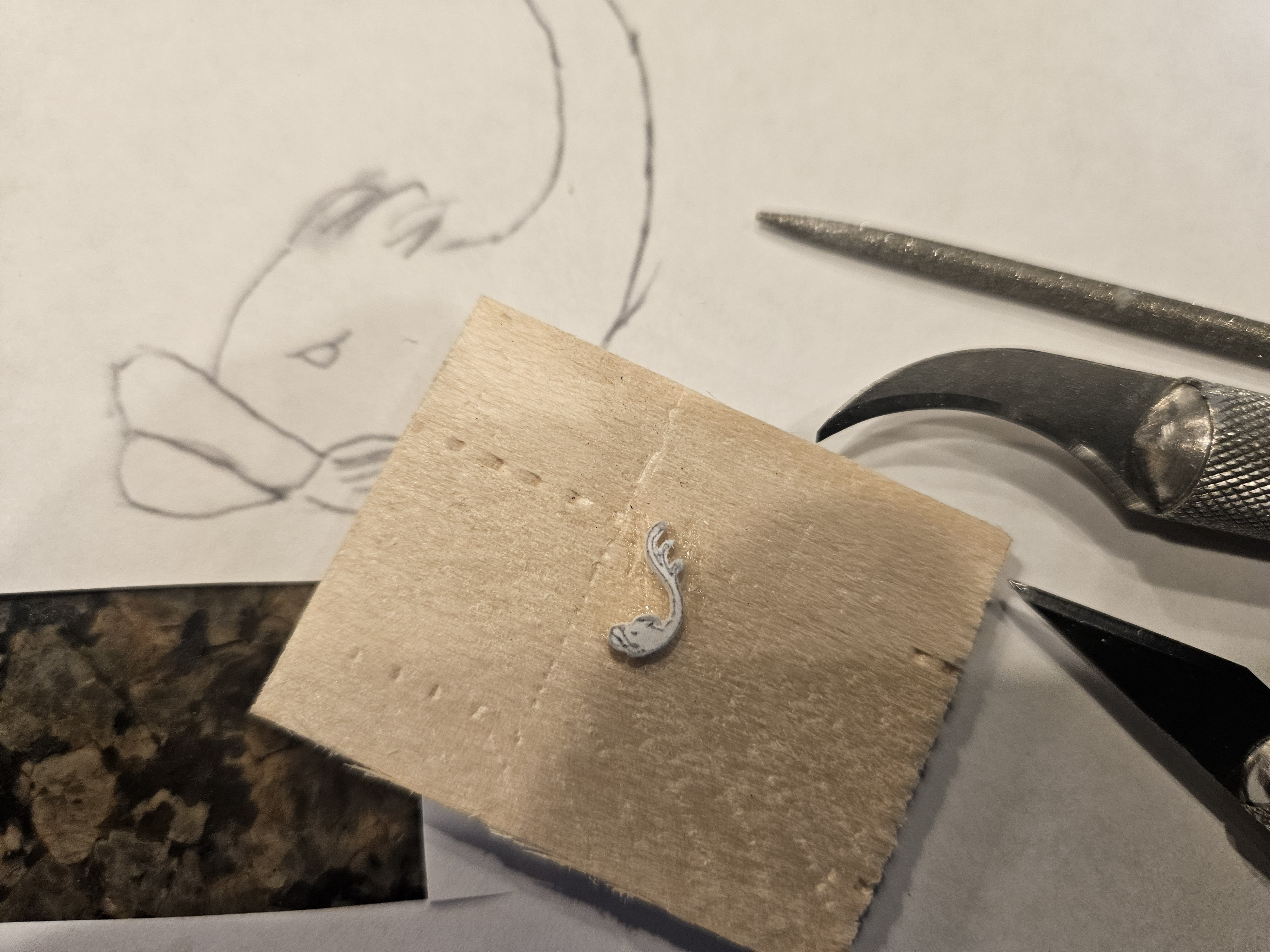
I just realized that I shouldn't even bother glueing the masters to wood! I redid a bathroom last year, and I have some leftover tile that is very smooth... that is what I need to glue the masters to.
- 432 replies
-
- 1
-
-
- soleil royal
- Heller
- (and 1 more)
-
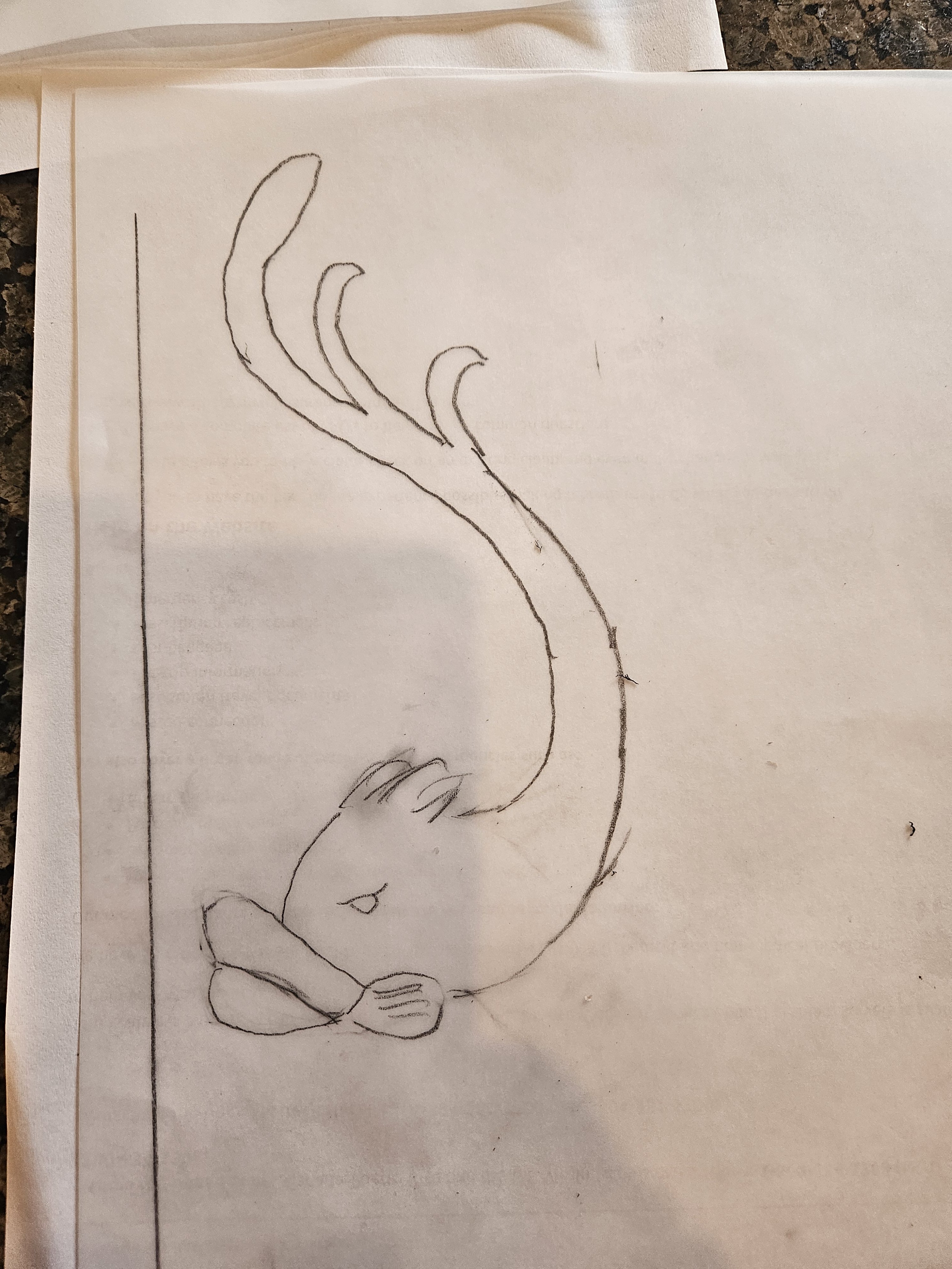
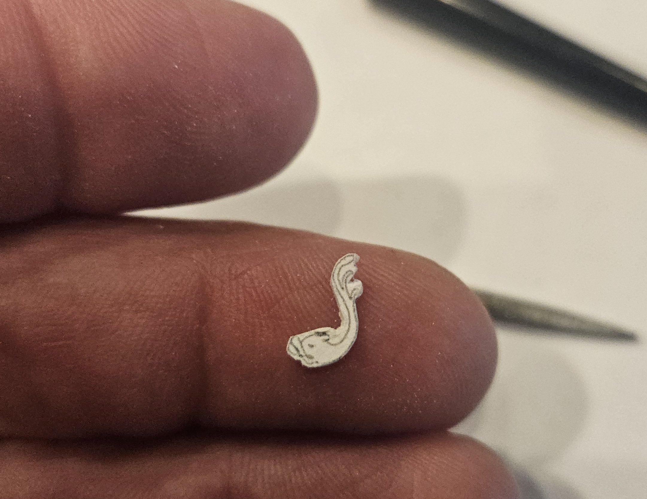
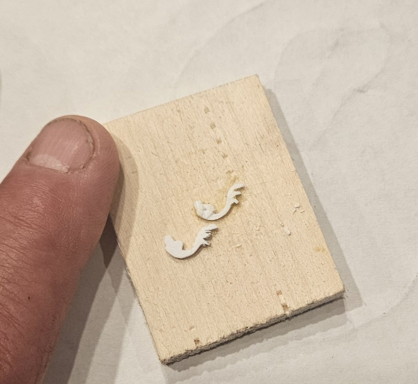
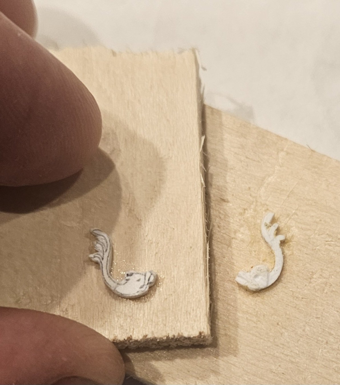
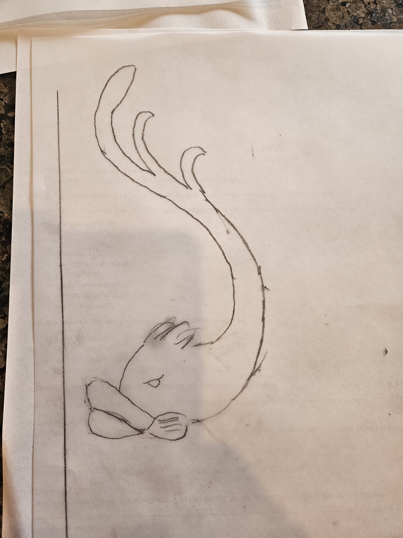
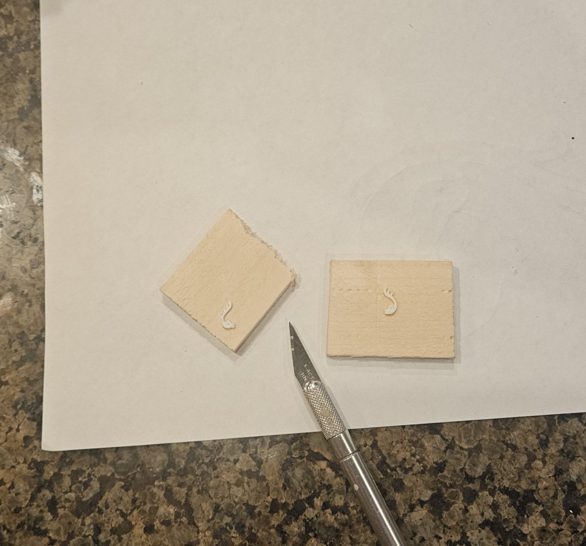
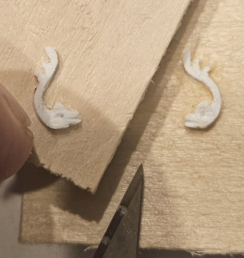
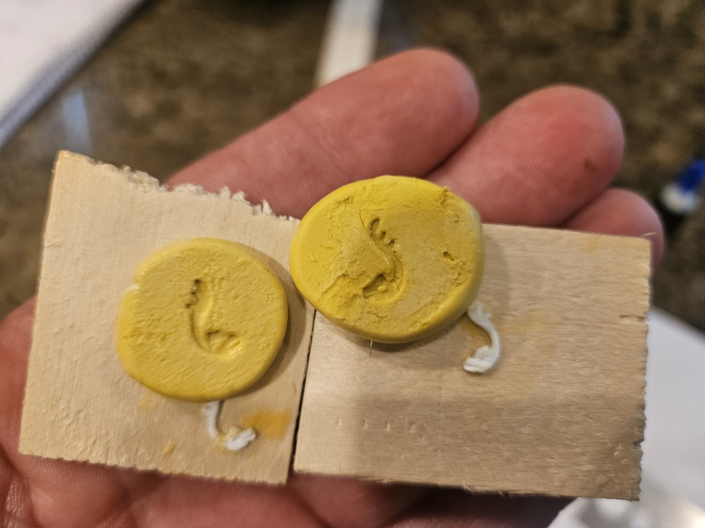
Taking Marc's suggestion to heart (dolphin head should face the gun port, tail flaring away), I went back to the vellum paper for sketching and ended up with this... After scanning the drawing into my computer, I just went into Word and shrank the drawing to a square 8mm x 8mm, then printed out some tiny dolphins that I glued to 1mm thick Evergreen sheet.I then perforated around the tiny dolphin with a very small drill bit, and with a bit of filing, got this for my right side of gun port dolphin (this is my second attempt at a right hand dolphin)... I also cut some blanks out for a left side dolphin, but I finished the right side first.. It took me 4-5 tries on the left side dolphin, as I just couldn't get a result that looked close to a mirror image... until I flipped the left side over and worked on it while it was laying next to the completed right side dolphin.. it was much easier for my brain to "see". Finally, I ended up with this pair that I am mostly satisfied with... I could continue to tweak and try again, but I reassured myelf that this is the view that people will see if they get their eyes within six inxhes of the ship (however, I may add the tiniest piece of clay behind the head of the left hand dolphin if I am not satisfied with the resin copies). It is interestng how just changing the position of the camera angle very slightly can make them look a lot different! And now the great reveal of the moulds.... ugg. Not happy. I will try making resin copies from these just to see, but I think I made a mistake glueing the pieces to a rough piece of wood (a cheap shim!). Notice the mould body doesnt want to release cleanly. Hmmm... maybe I can sand around the pieces to smooth the wood a bit, and then coat the wood surface with a very thin cyano acrylate to seal the surface? Suggestions welcome, as I think if I try and pry off the pieces, I will ruin them...


- 432 replies
-
- 4
-
-
- soleil royal
- Heller
- (and 1 more)
-
Marc, I did drill perforation holes around the first one (the one in the picture below). I just tried a second one without perforation, and it didn't do well. By "abut", do you mean the tail should be a little more to the left? This is as close as I can get the dolphin without butting up against the (future) gun port tackles
- 432 replies
-
- 2
-
-
- soleil royal
- Heller
- (and 1 more)
-
Well, I wouldn't call my latest 180 degree turn a reversal.. I would simply call it listening to someone with a lot more experience at this than me! While I thought that I would glue the hulls together, paintt the hulls, and then add the decorations.... Marc LaGuardia has suggested that glueing on all of the decorations first, painting the hull, and then painting all of the indiviual decorations is the way to go. And that makes sense, especially from a glue smear standpoint, and all of the tiny scraping that I would have to do to apply the decor. So.... onto the decorations. 1) rear bulwarks and beakhead bulkhead will display a field of fluer de lis, and I have molds on hand 2) upper gun deck gun ports will be bracketed by dolphins 3) middle gun deck ports will have "trophies of war" spaced in between them. I decided to try a dolphin first; I will need a mirror image pair to make resin molds of. I drew a dolphin on vellum after finding lots of "dolphins on French furniture" pictures. I wanted a large head and a slender body, and I liked the wood carving with oversized lips (duck lips?!). I took the drawing and scanned it, then was able to make tiny little prints that measured 8mm tall... the vertical height of the upper deck gun ports. . I decided to try 0.5mm thick sheet fr the first go around, and glued the little prints to the Evergreen sheet stock. So far, maybe so good. Very fragile but nothing has broken so far... After about 90 minutes of very gentle cutting, filing, and scraping... I am satisfied with my first attempt; I know that Marc and others have said in their logs that the trick is to create some texture that catches the light. I know that my second carving will be better than the first, and the third better than the second, and so on.... I have also made moulds for the trophies of war that I had cut out from the quarter galleries fully a year ago (before I completely changed course with the high sheer wales). However, oops... some of the trophies of war will be too big to fit in between the wales. Sigh....... I may end up also creating some trophies of war that are small enough to fit in between the wales! It's only time, right? So hopefully my carving skills will improve with practice, as I am looking at a lot of intricate carving over the next several months!


- 432 replies
-
- 3
-
-
- soleil royal
- Heller
- (and 1 more)
-
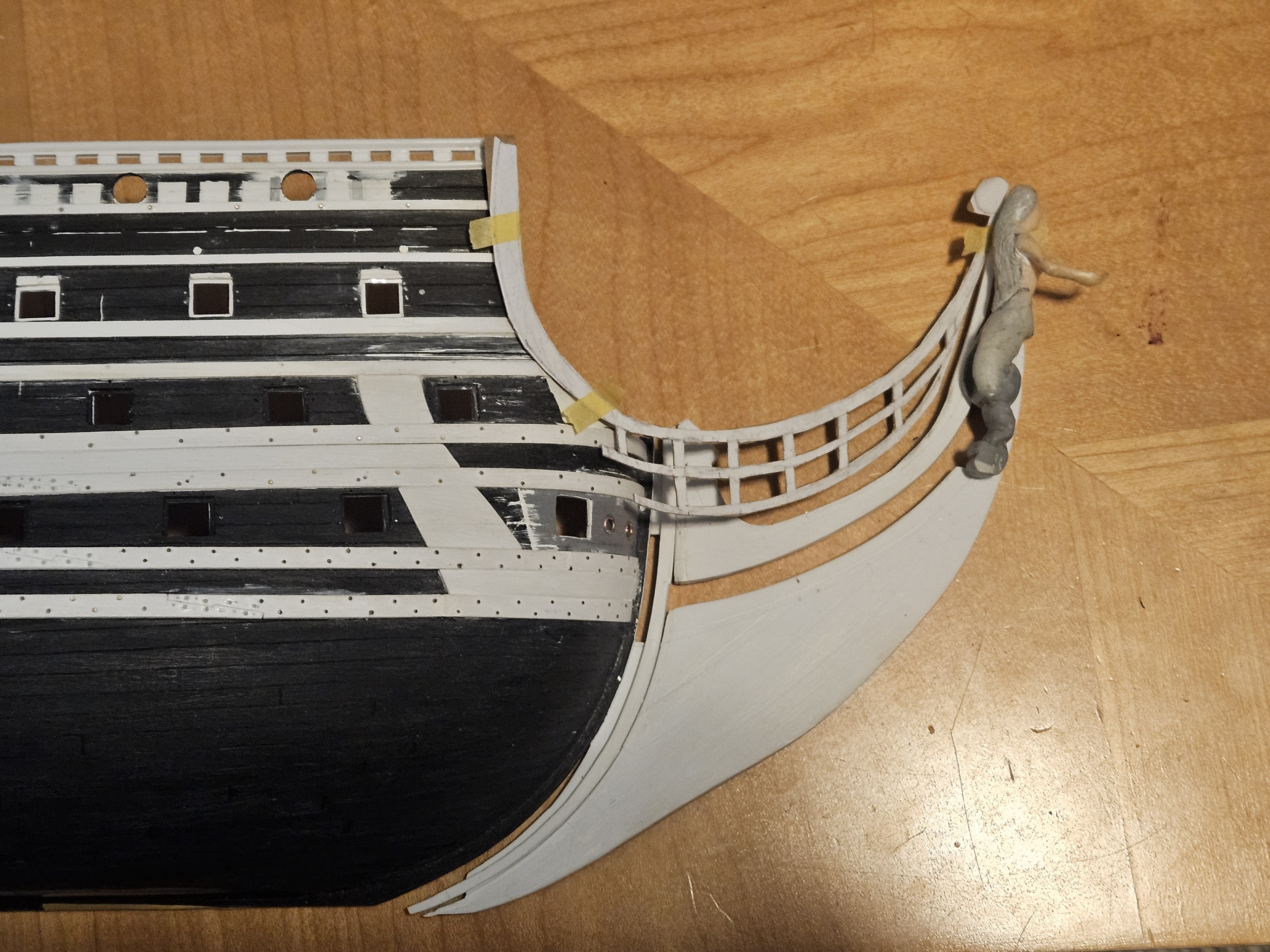
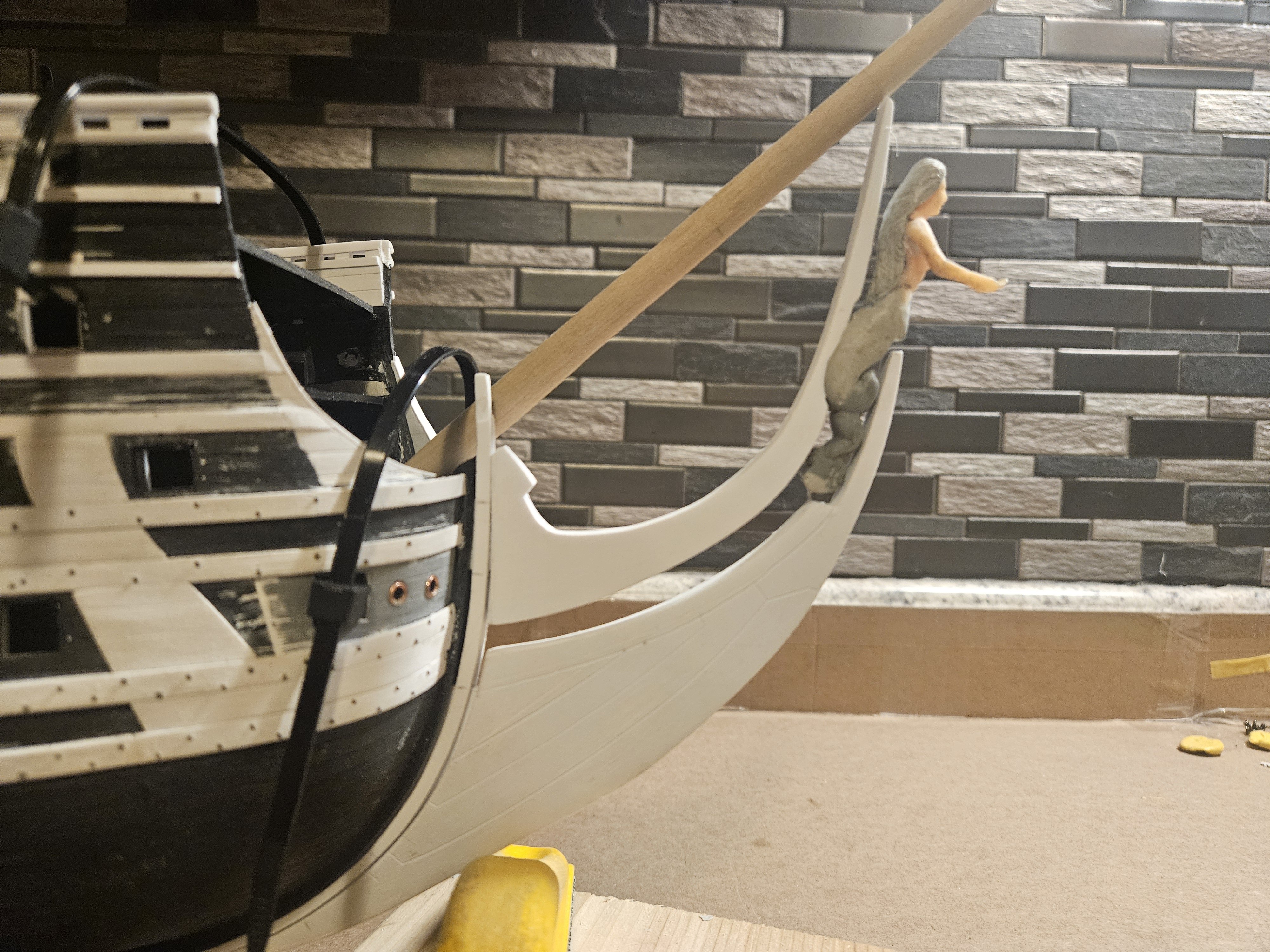
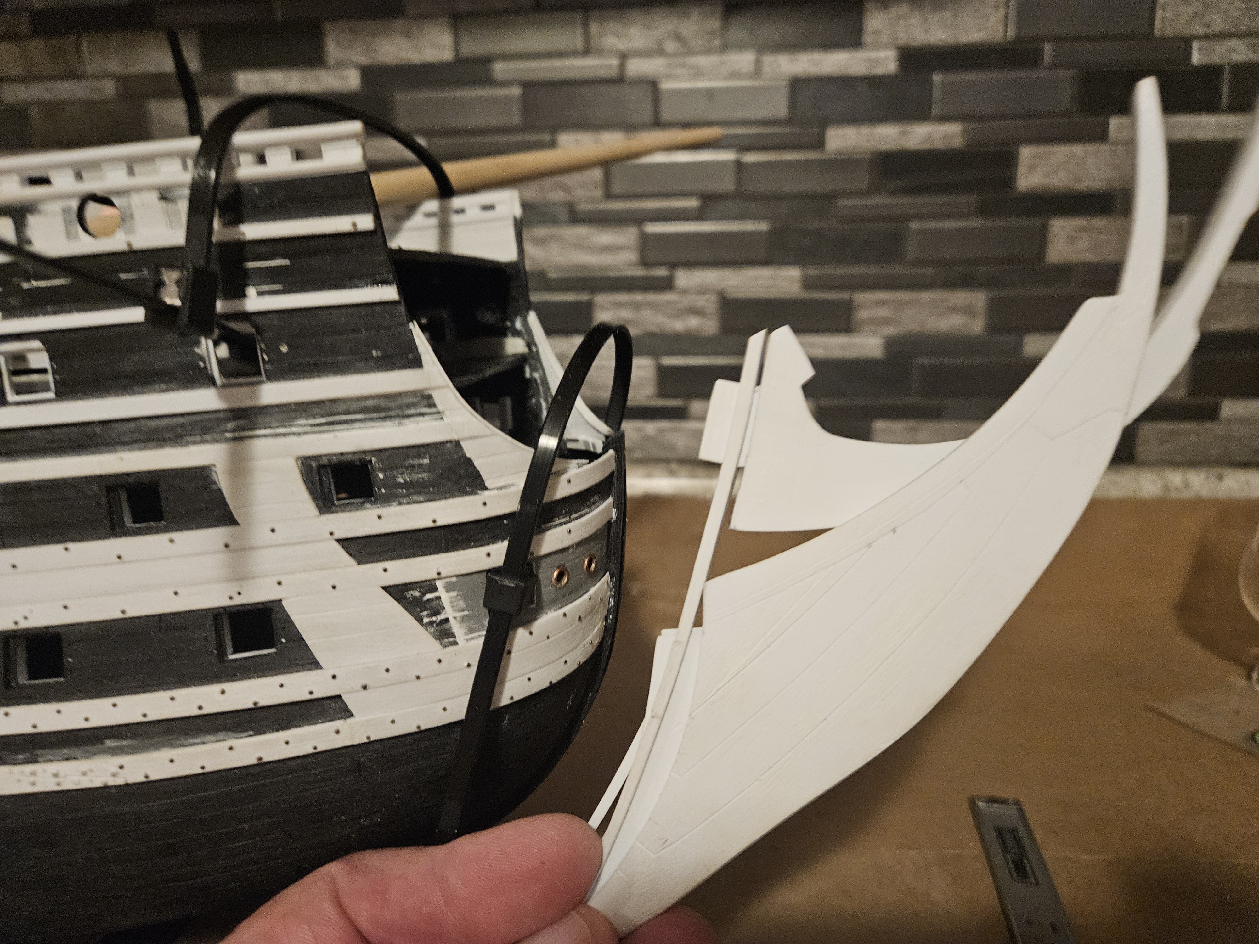
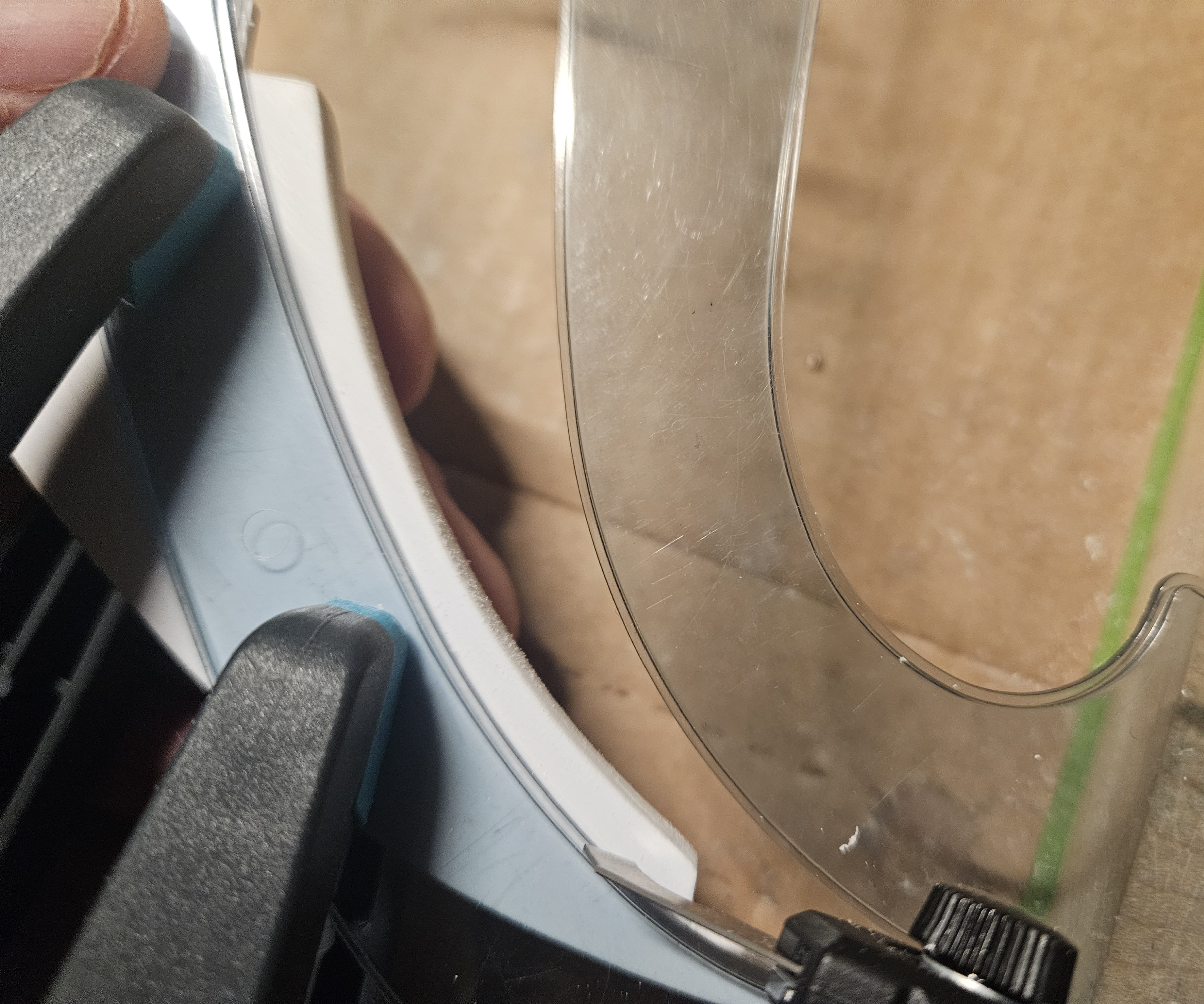
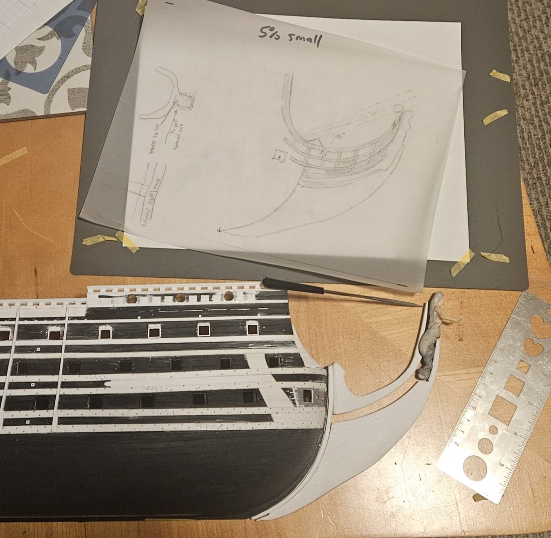
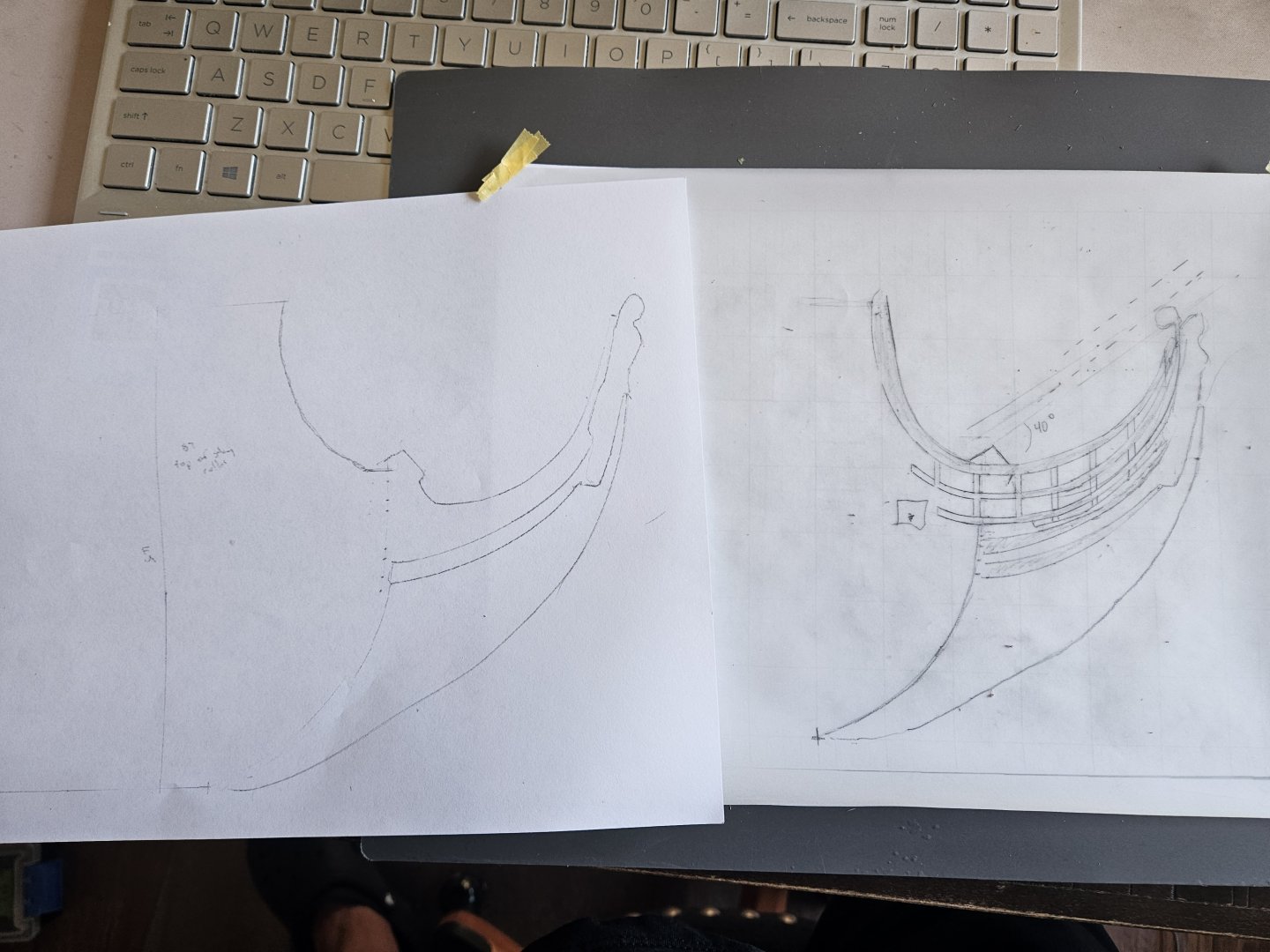
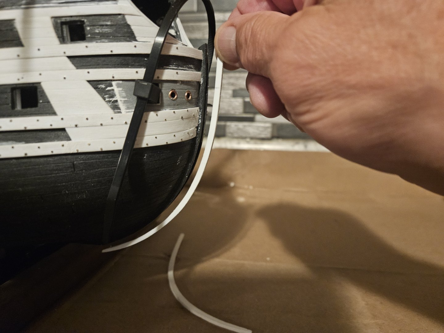
Well, that went well... the card template fits as well as I can make it fit right now. Guess I can take a deep breath and next step is... glue the hull together. Whew - started down this beakhead bulkhead/head redesign process on Dec 27.... I did miss 5 weeks of ship time in March/April, so it has only been three months, not four.... The one observation that I have is that I was hoping to make the head look a little longer and lower than it is. It is clearly longer than the kit, but - and here is just another one of many compromises that must be made - I opted to capture the 40 degree steeve of the bowsprit for a 1660-70 period ship. Or, I could have stayed with a steeve of 31-32 and I would have my lower head, but not an accurate bowsprit angle!

- 432 replies
-
- 3
-
-
-
- soleil royal
- Heller
- (and 1 more)
-
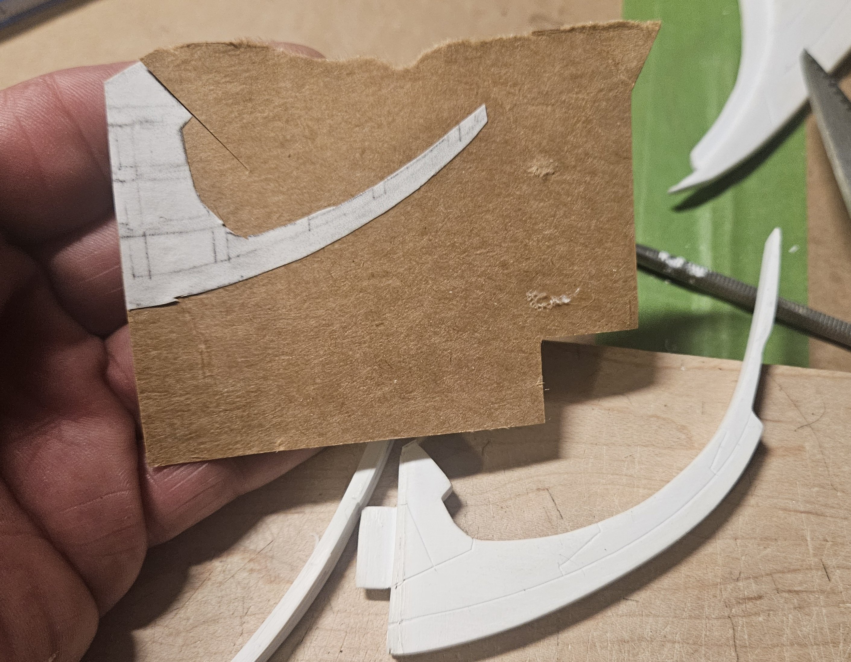
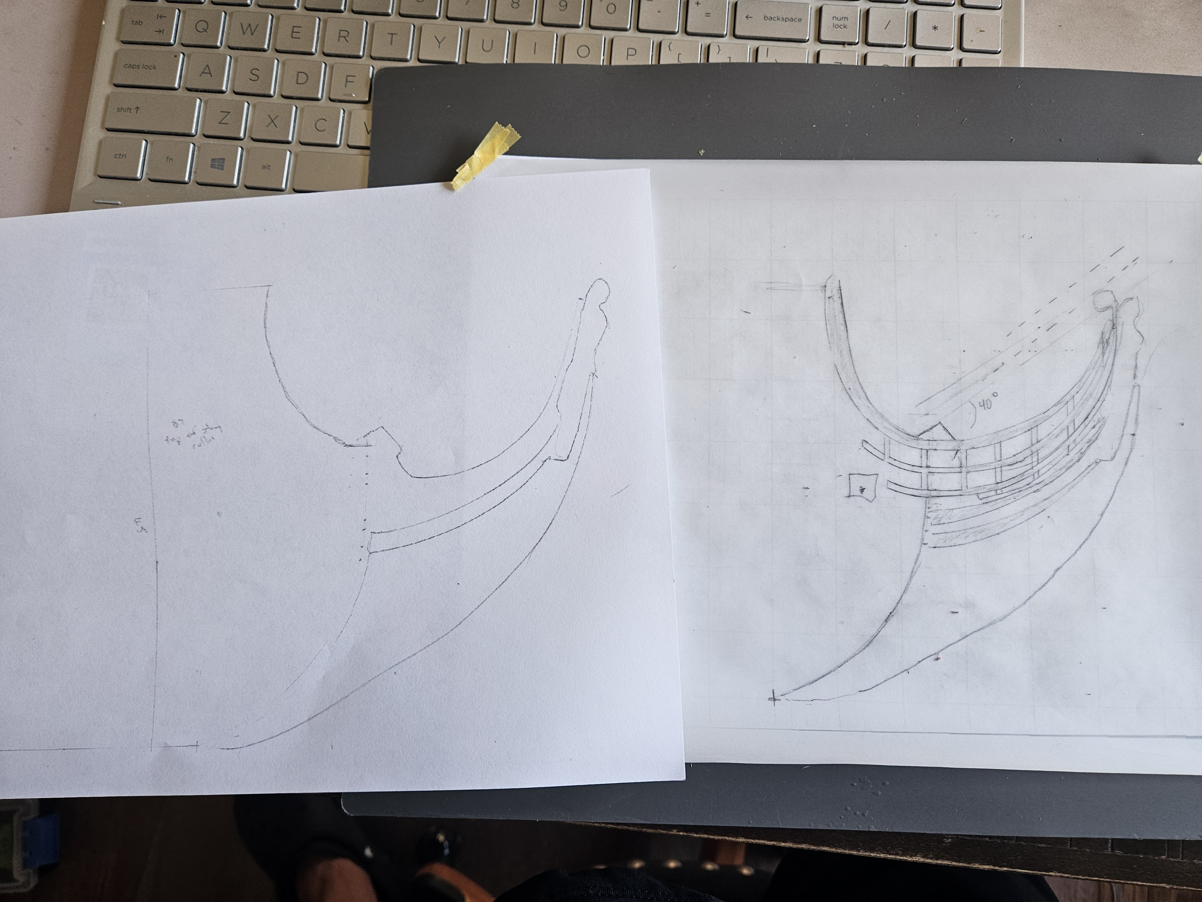
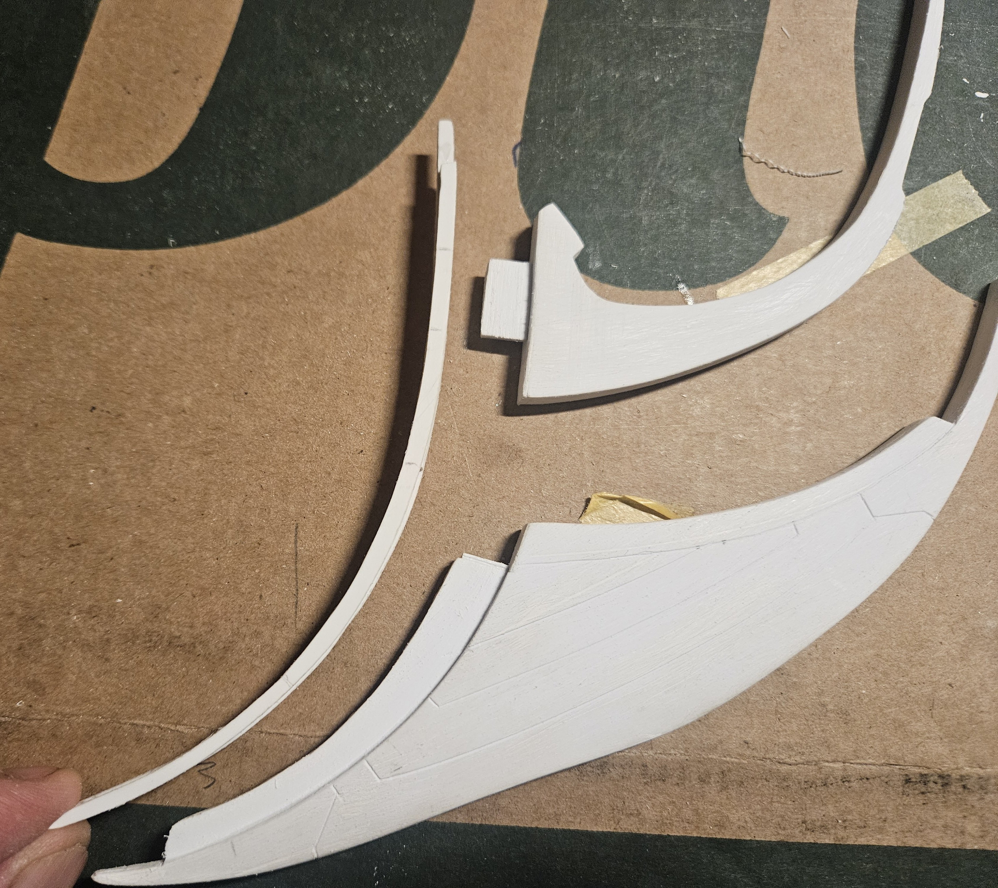
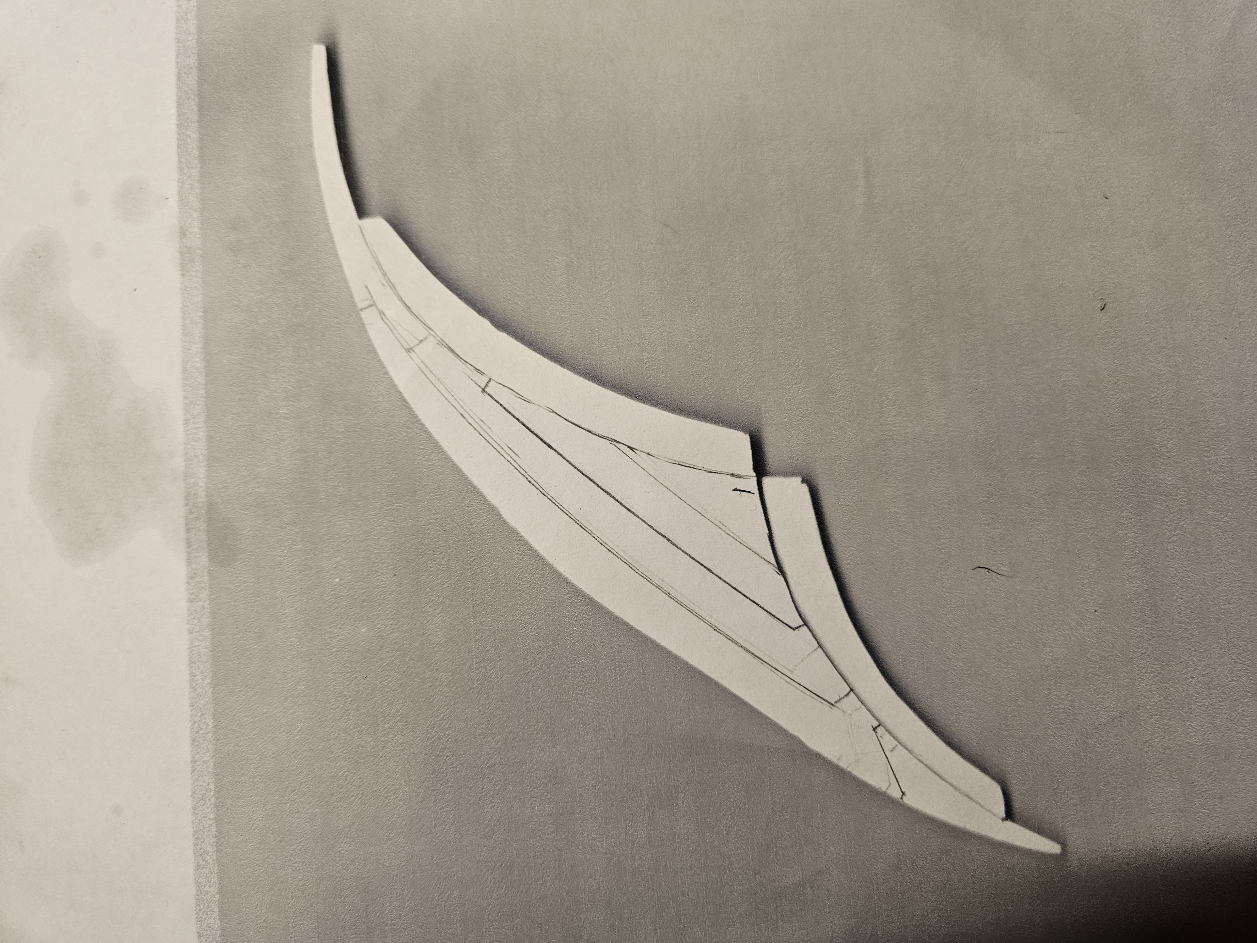
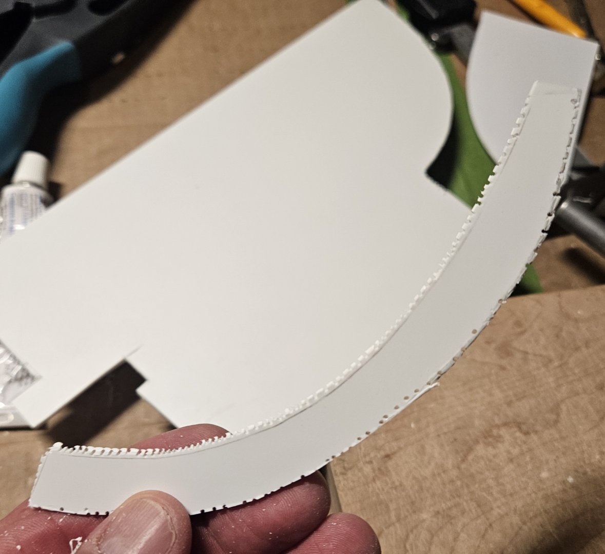
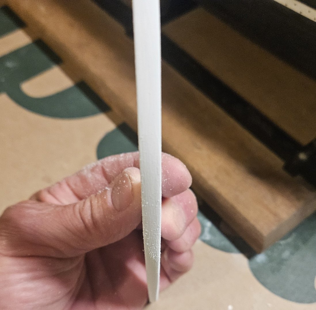
So... hopefully my next post will be showing cardboard templates of head rails... but first..... I needed to trim down the top surface of the upper knee. Note the cardboard template is much thinner than the current styrene version as it tapers on its run to the back of the figurehead (I cut the cardboard template off where the base of the figurehead sits on the lower knee for ease of use). The hair bracket is lightly sketched in... it will be 5mm in width at the stem and will taper to 1-2mm in width by the time it reaches the base of the figurehead. However, the top edge of the upper knee needs to: 1) duplicate the curve of the hair bracket and 2) have an even 2mm rise above the hair bracket curve. This 2mm rise above the hair bracket will support the head rail support brackets... BIG thanks to Marc LaGuardia for helping me to understand this relationship! So... I am going to start making cardboard templates of the top head rail, and go from there. I do have to consider the perspective of my sketch, though, as the sketch is only 2-dimensional, and the distance from the top of the beakhead bulkhead to the rosette is a straight line 100mm in length. However, in the 3-dimensional world of the model, the straight line length is 120mm or so, as indicated by the needle file. So maybe I just have to make a copy of my sketch, and lengthen it by 20% to lengthen the head rail? Regardless, I expect there will be a lot of trial and error here, but this is a required and critical step. Once the knees and the head rails and the fifurehead all fit perfectly... then the hull can be glued together. That sort of scares me, as that means painting is coming, and that will be a whole new learning experience!

- 432 replies
-
- 3
-
-
- soleil royal
- Heller
- (and 1 more)
-
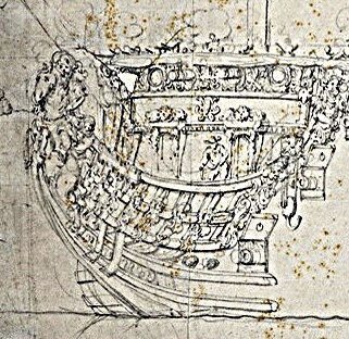
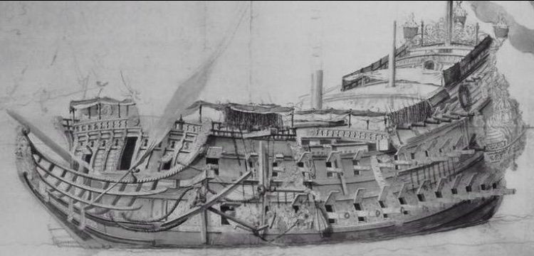
We shall see, Marc... but I am certainly glad that I finally took your observations about drawing/creating on vellum to heart. I had made rough sketches of the head structure based on measurements from various VDV drawings. Now, as I draw on the vellum to try and be precise to the millimeter, it turns out that after scanning the hull and head structure onto vellum and cross-checking the proportions... I lucked into the exact head structure proportions that I was trying to achieve. However, that was mostly luck! There is no way that I could attempt to make the head rails and support brackets without having a very good drawing. And... gee, have you heard me say this before? - it turned out to be one heck of a lot easier than I assumed! Here are several of the head structures that I was trying to emulate... especially Royal Duc, the little sister. After looking at some of these Dutch ships, it seemed that there heads were plain and not dressed up. I was wondering if SR 1671 might be "staid and conservative"" in that respect.However, Royal Duc (and Royal Louis) seem to be taking the approach that any area is a good area for Baroque. Since SR 1671 was intended to showcase the magnificence of Louis 14... well, Royal Duc has a lot going on with the head and the beakhead bulkhead, so SR 1671 must be at comparable..
- 432 replies
-
- 1
-
-
- soleil royal
- Heller
- (and 1 more)
-
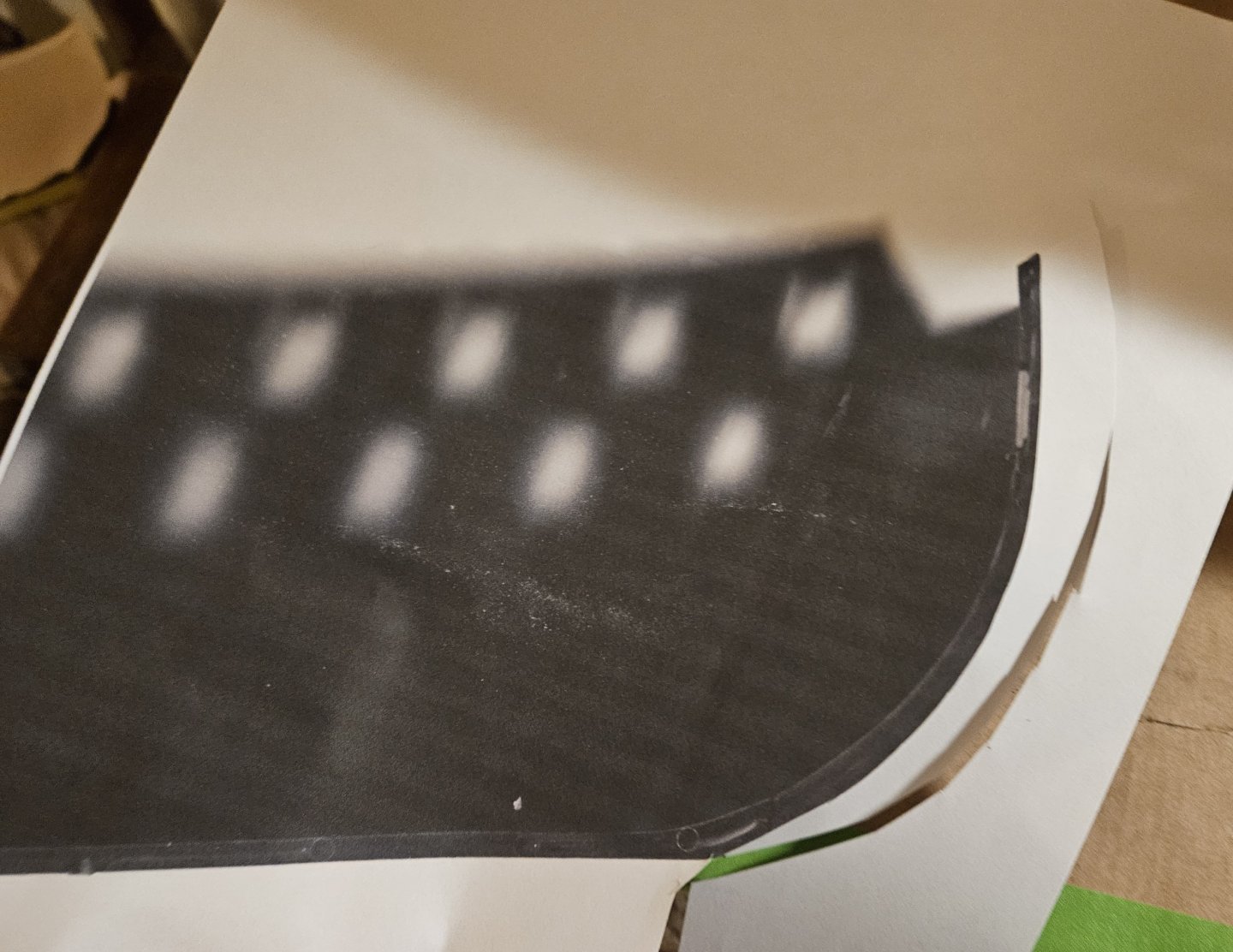
In order to create card templates for my head rails, I need a precise pattern. I finally got around to drawing on vellum. I scanned in the ship hull and new head parts that I created, and then saved than scan. I then printed it on vellum directly from the printer, and I had a pretty good template. It took me several hours of measuring and drawing with French curves after looking at a number of VDV drawings to try and capture that "older" type of Dutchy head rail. I was satisfied with the somewhat finished drawing on the right. There - I had the basis to start cutting head rail card templates! Except... something wasn't quite right... I laid the hull on the vellum drawing for a final check... and it was off. I discovered that my vellum drawing was 4.9% smaller than the original... that sounds small, but it was plenty big enough to create seemingly huge errors! I rescanned again, and got the same result?? I checked Google, and apparently "minor" scan size errors are not uncommon; it suggested a few minor fixes. The print on the left is now exactly the same size as the original scanned drawing.... so I will print the drawing on the left on vellum, and draw the head railings again.
- 432 replies
-
- 3
-
-
- soleil royal
- Heller
- (and 1 more)
-
OK, the fit is so much better with this stem padding. On to the head rails... Note to self. In the future, make sure polystyrene work doesn't have to be flexed to fit into place... it should fit without stress/strain, if possible.


- 432 replies
-
- 3
-
-
- soleil royal
- Heller
- (and 1 more)
-
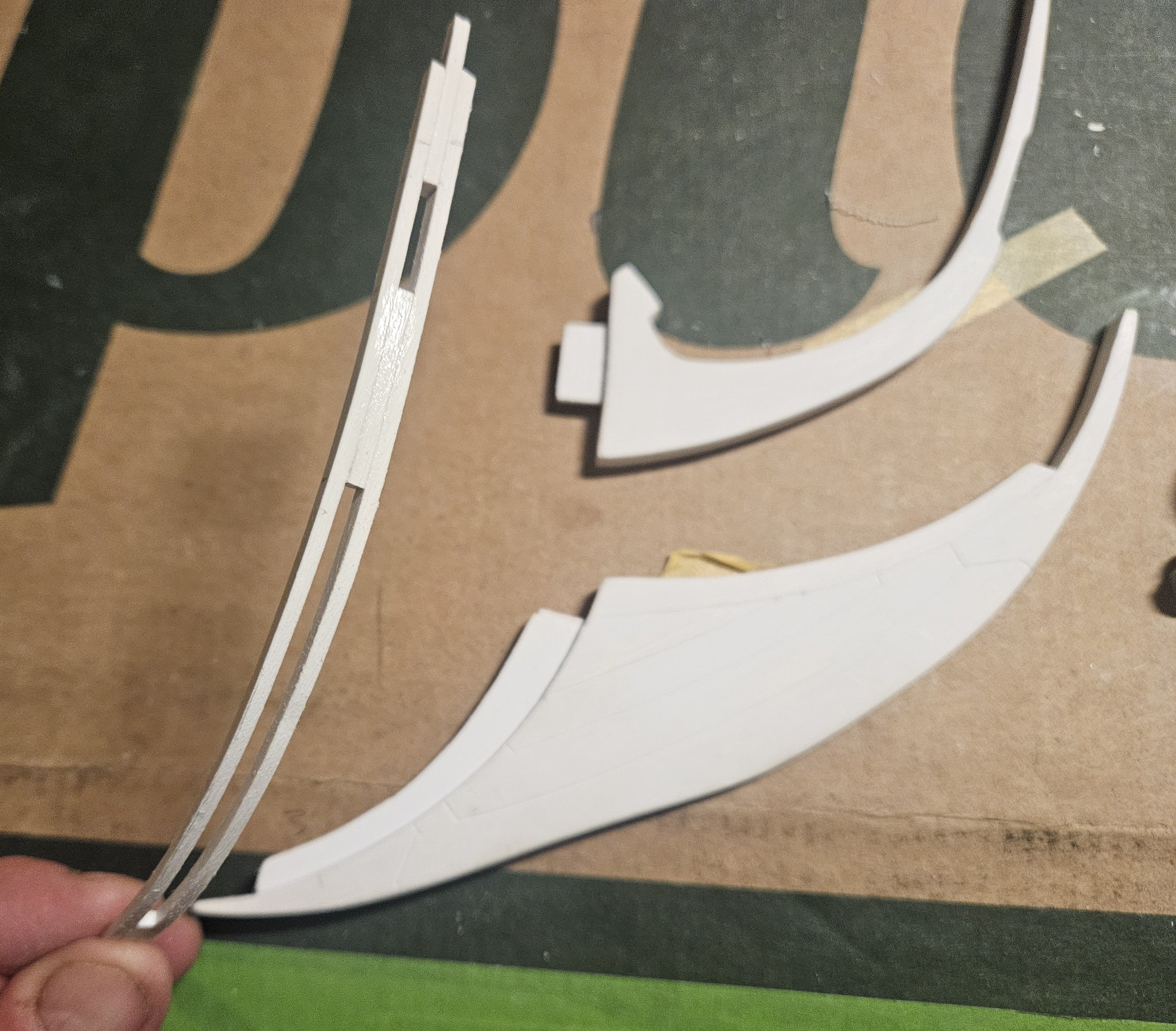
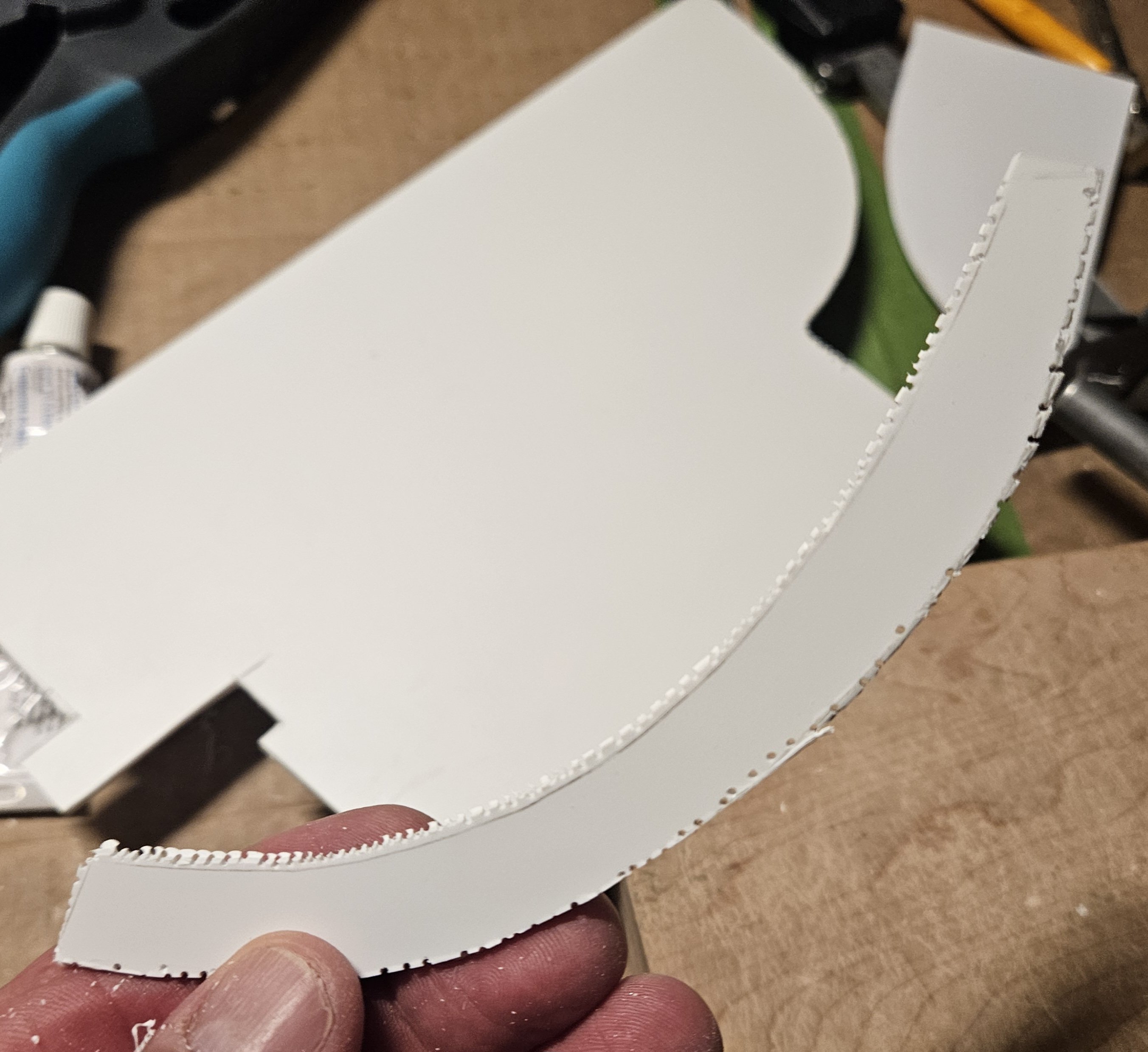
My goal of building as much of the "from scratch" head structure in advance and to also have a precise fit is not going to work with my current stem padding piece. I wanted to make the stem thicker, a uniform 5mm thick when viewed from the side, and 6mm wide when viewed from the front. I also created slots that match the kit openings in the hull, so the tabs on the head pieces lock into the hull. The problem is that I built a straight piece that needs to be flexed to the curve of the stem; it fits perfectly, but pushes like a spring so I simply cannot get the head structure to sit nice and tight (at least without glue, but I can't glue yet). So I need a curved stem padding piece that fits with no bending stress/strain. Back to the drawing board. I scanned the hull to get the precise shape of the stem. Then a card template was made and affixed to 2mm thick thick styrene and it was drilled out. After wasting away the excess and then some sanding, the new stem padding piece fits precisely with no bending/flexing required. Now I just need to follow the same process and make several other curves so I can laminate them together to make a 6mm wide piece (viewed fore to aft). Now, the head piece tabs will insert through the padding into the hull, where I can use small clamps on the tabs to hold them firmly on the inside. So maybe 2 steps forwards, and now one back.... but I will get much better results as I create the head structure.

- 432 replies
-
- 3
-
-
-
- soleil royal
- Heller
- (and 1 more)
-
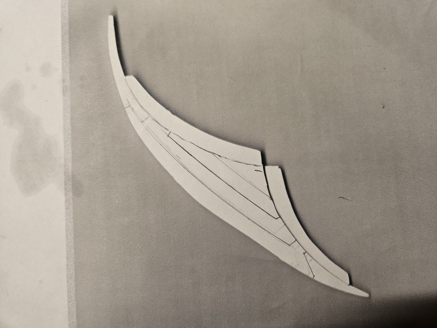
Well, the rough scribing of the port side of the knee of the head is done... just some cleaning up amd prettying up is required. I used two techniques to scribe: 1) a Tamiya scriber against French curves, and 2) Marc's technique using a very sharp blade to score the styrene. Both techniques produce excellent results; if I couldn't clamp a French curve to use as an edge, I was very comfortable in using Marc's technique. And I have to say again, this was another example of scratch building on this kit that I was initially a tad bit worried about - "can I actually do this?" - and with patience and the right tools and advice from experienced builders like Marc... it was so much easier than I expected... and fun!

- 432 replies
-
- 3
-
-
- soleil royal
- Heller
- (and 1 more)
-
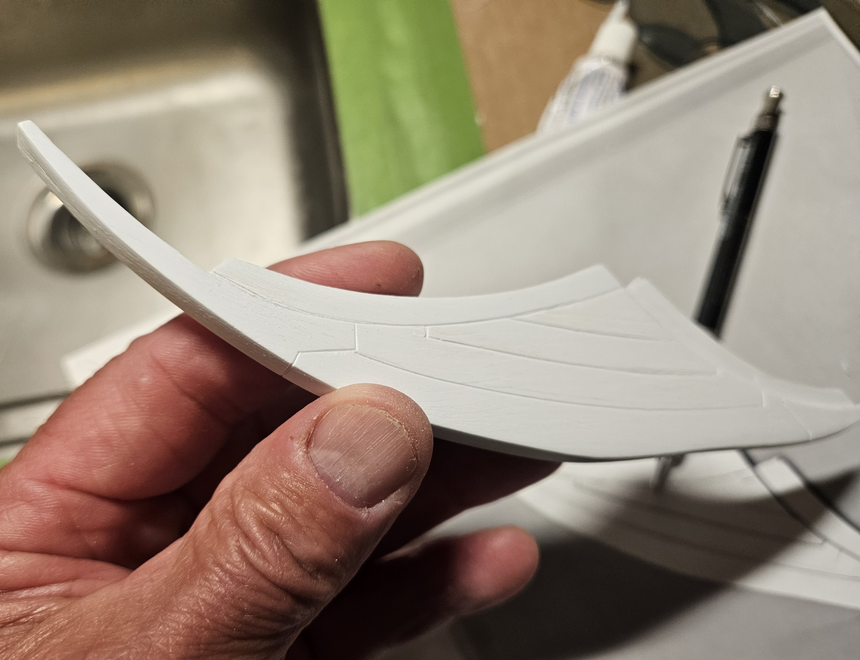
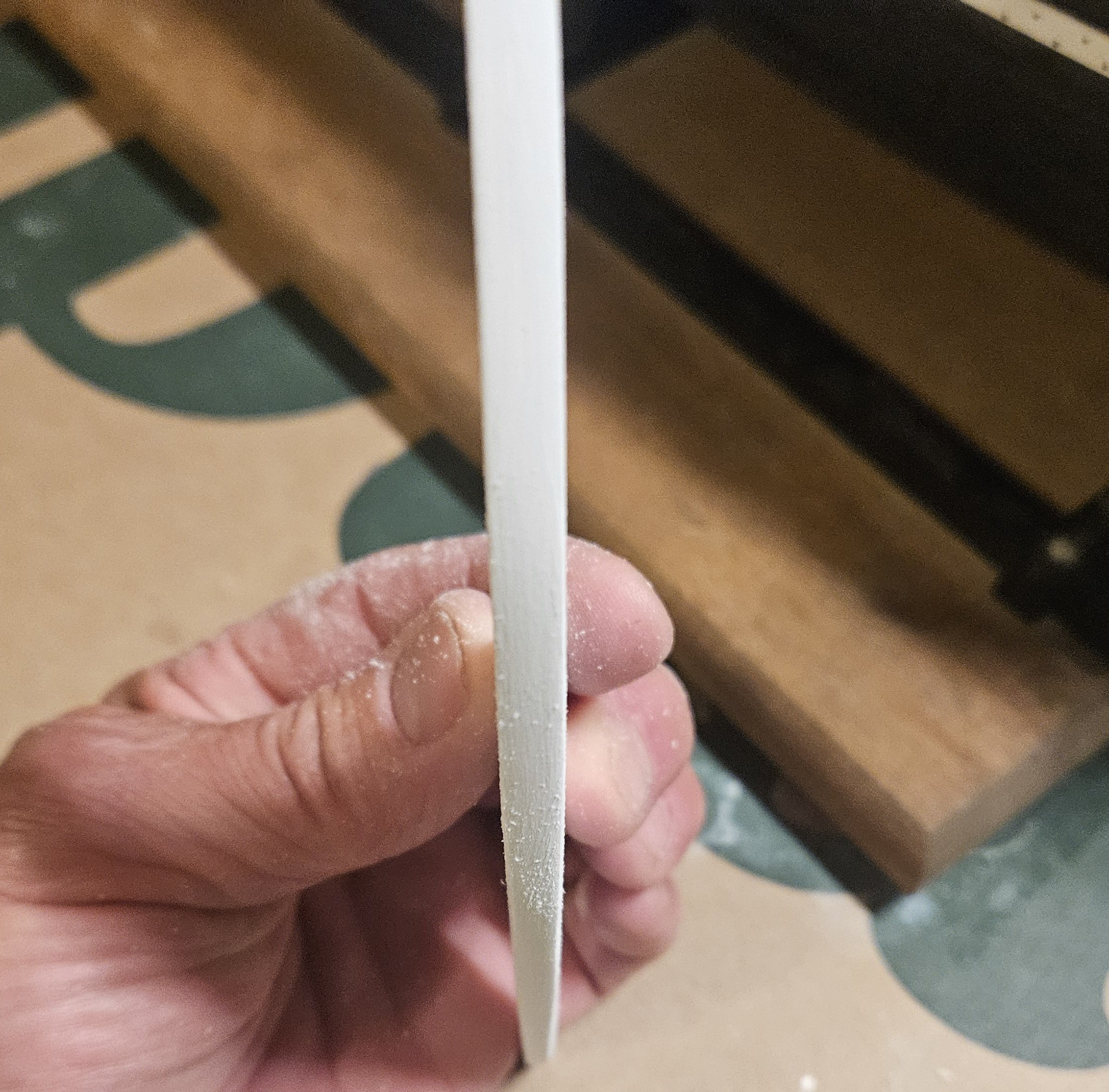
Marc's taper explanation above really helped... in simple terms for my mind, it means that even though the curve of the cutwater viewed from the side may be a curve 6" long, the ocean sees the frontal view, and the curve now appears to be a simple straight piece only 4" top to bottom, but the taper must appear even as Marc drew. I also tried to evenly plane down the thickness from leading edge back to the stem... Next, I monkeyed around for an hour penciling and erasing and finally came up on a joinery/scarf joint pattern that looks plausible- to me! Now... the fun part comes... the actual scribing. The only way - with my resources- that I can do this is to clamp the French Curves that made the lines directly to the knee of the head piece so I have an edge to scribe against. No way I could ever scribe freehand without an edge! As soon as I finish a particular scribe on one side, I will immediately flip the piece over and reclamp and scribe the companion line...

- 432 replies
-
- 3
-
-
- soleil royal
- Heller
- (and 1 more)


.jpg.16ab1ce9e23d21ca3be6996ed6aecac3.jpg)


.jpg.45dbb725dcd2c00c065aa7fd72a3c524.jpg)