EricWiberg
-
Posts
224 -
Joined
-
Last visited
Content Type
Profiles
Forums
Gallery
Events
Everything posted by EricWiberg
-
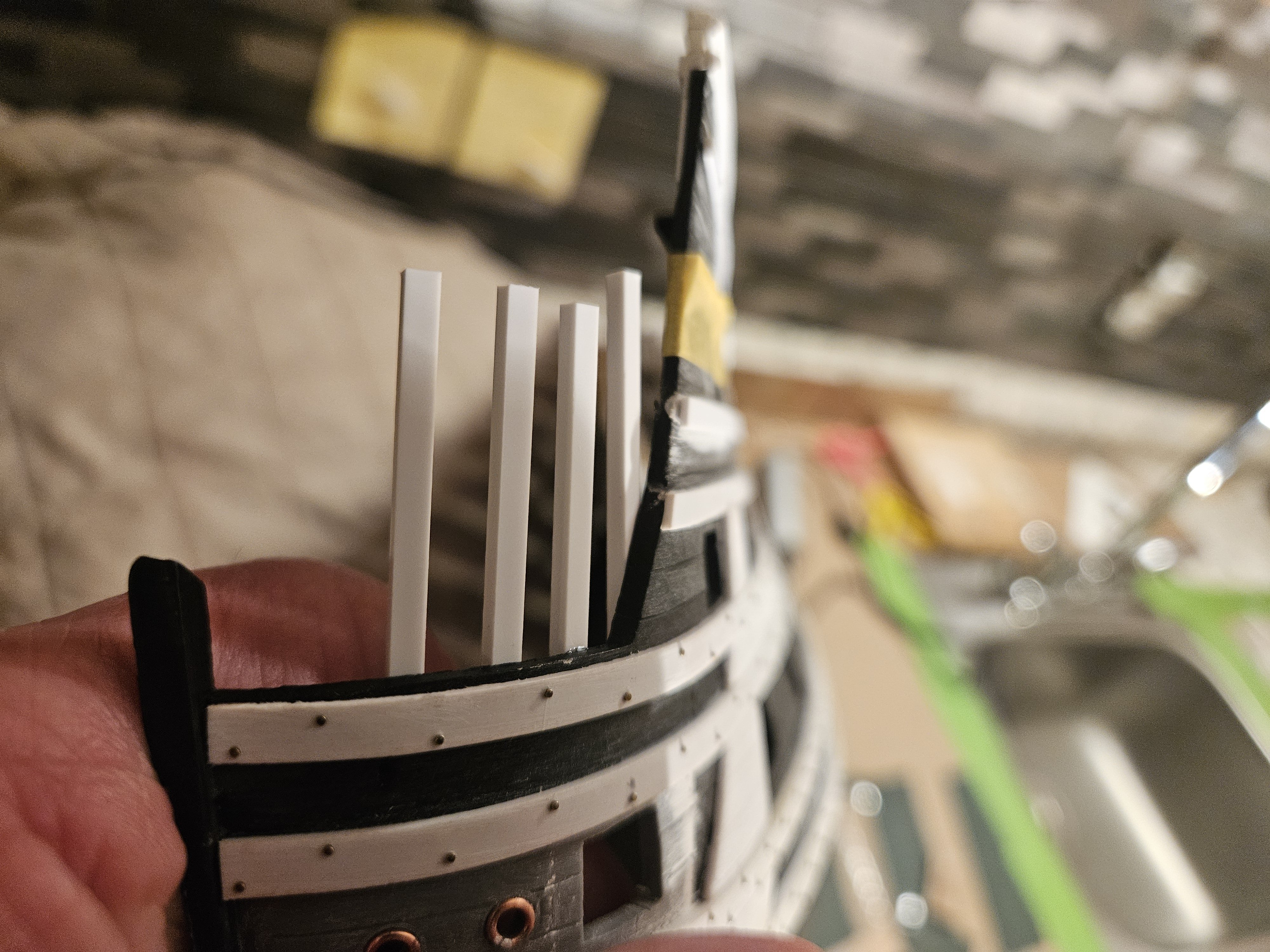
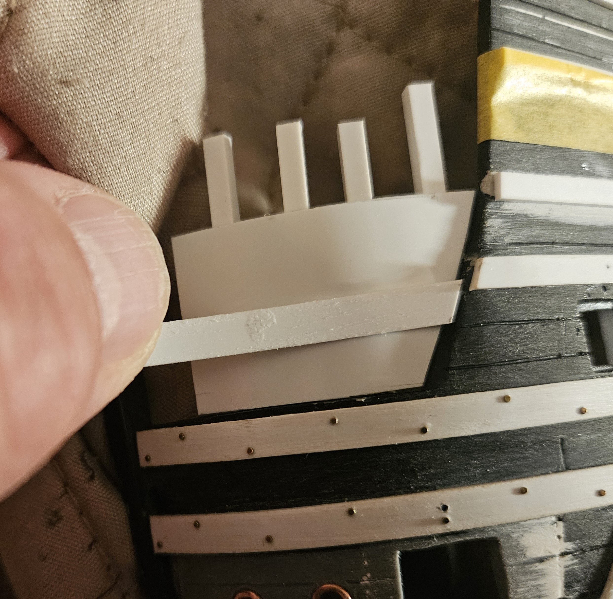
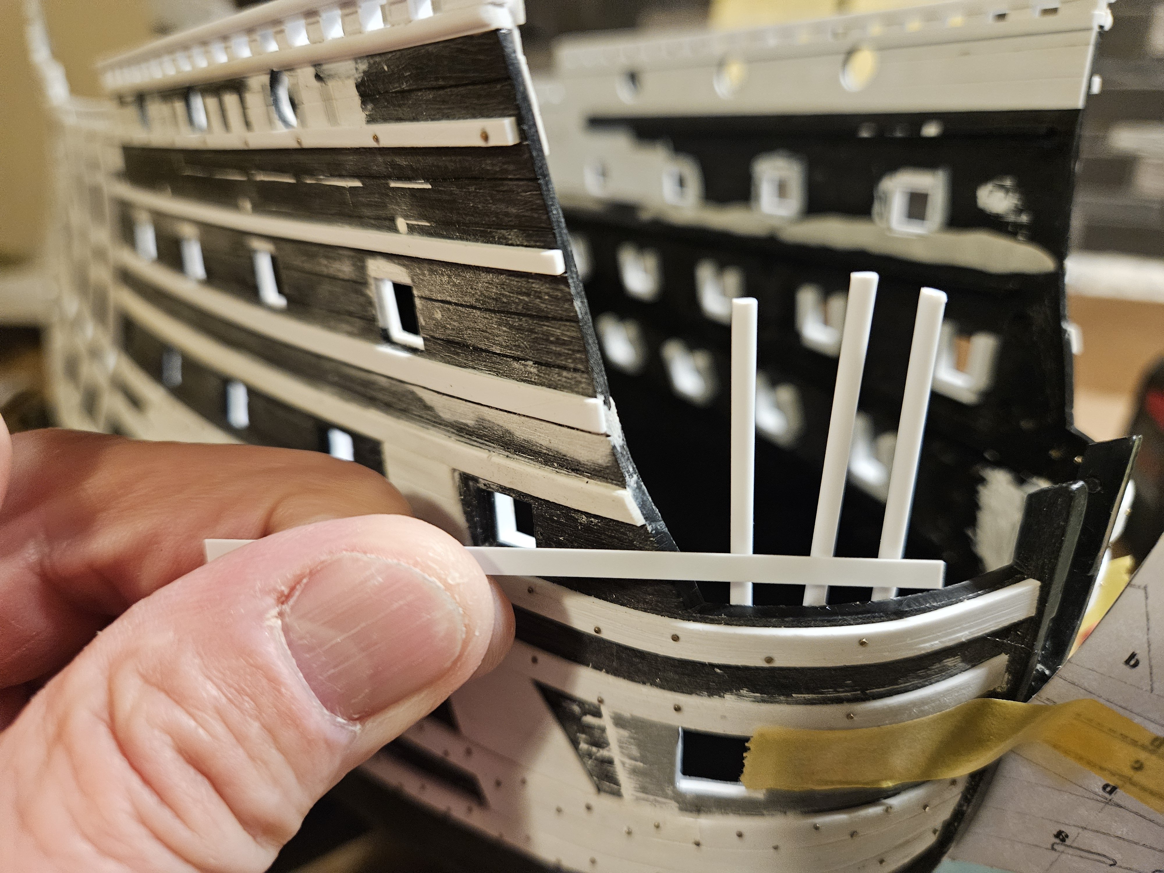
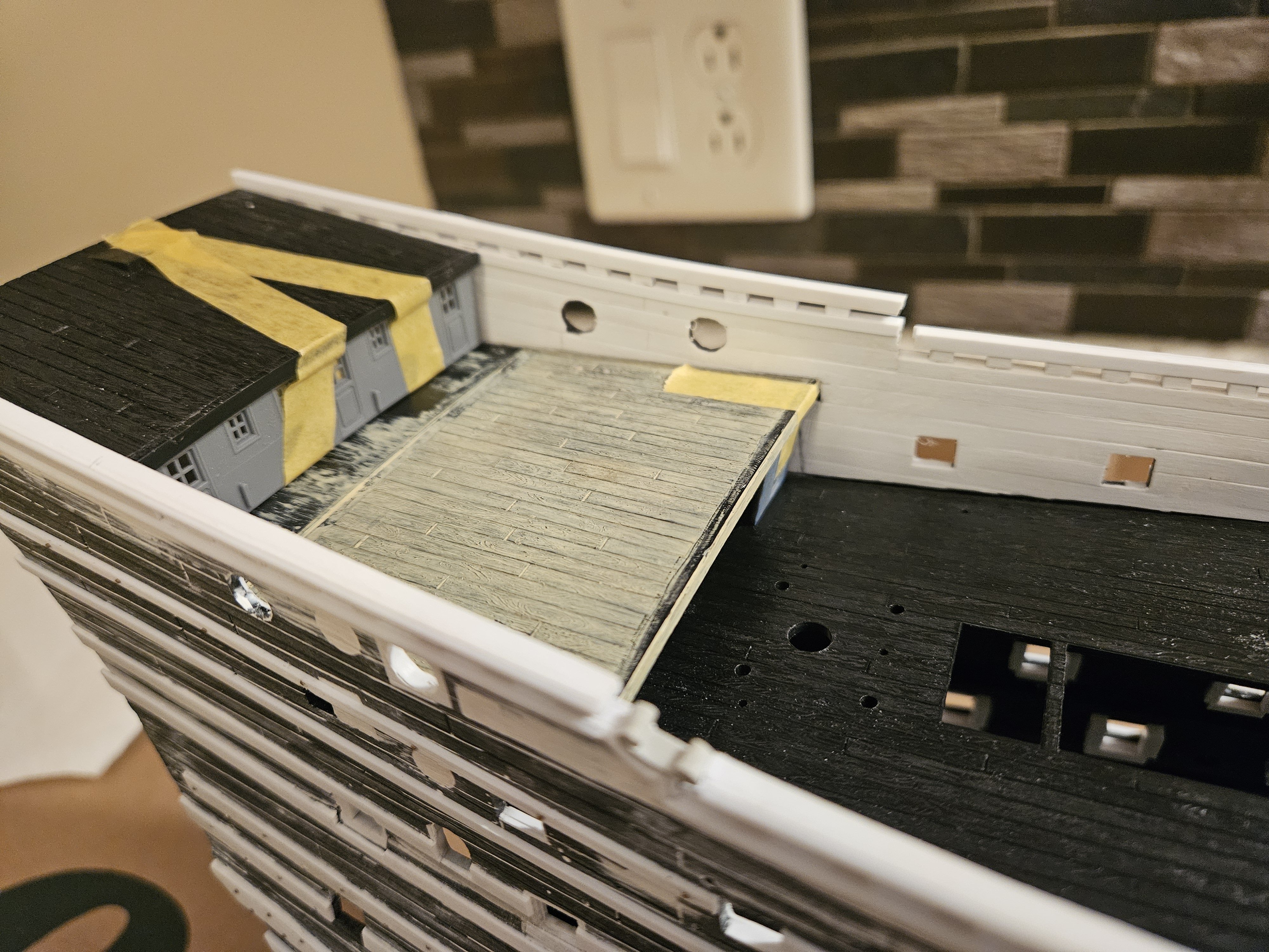
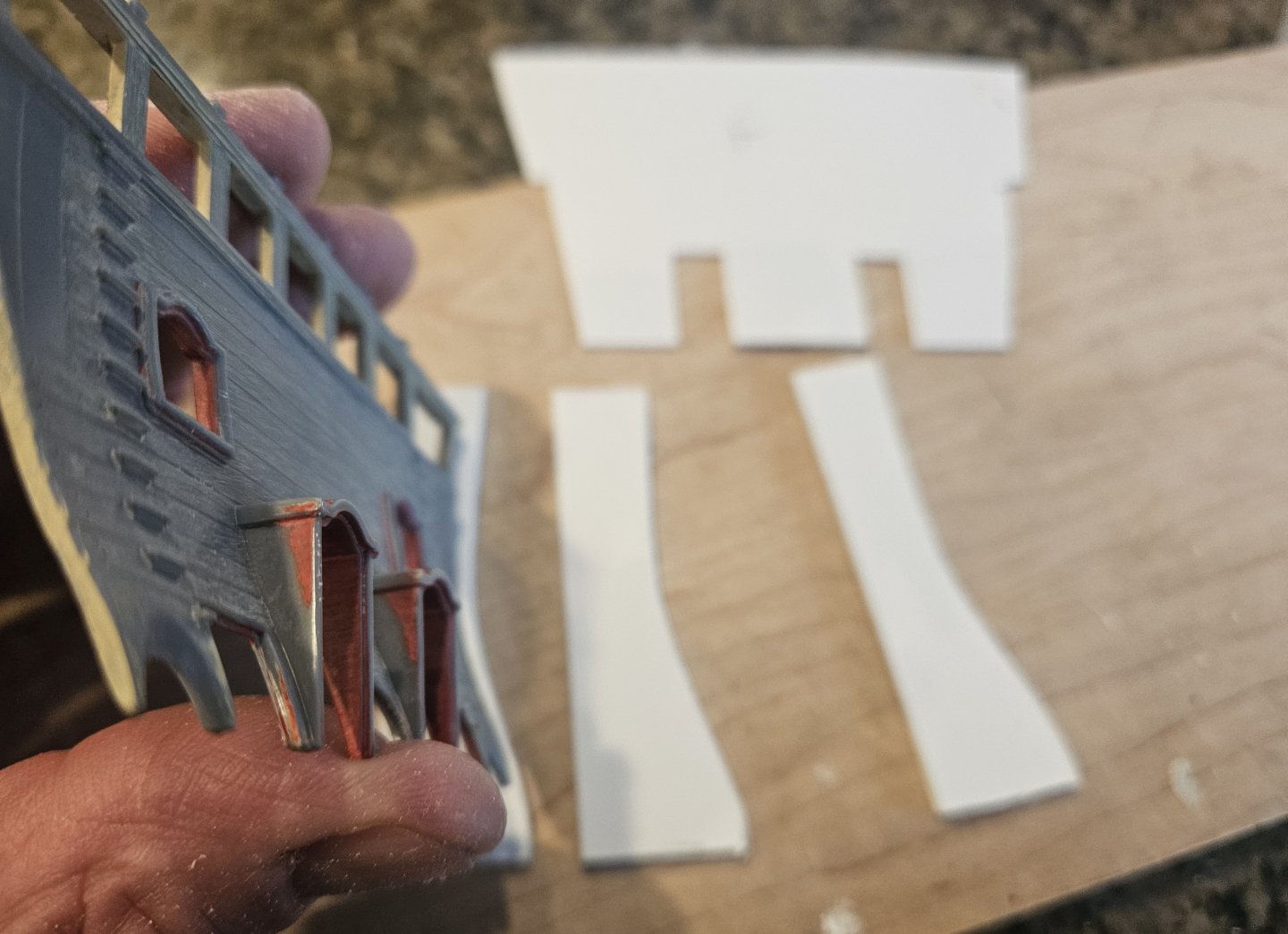
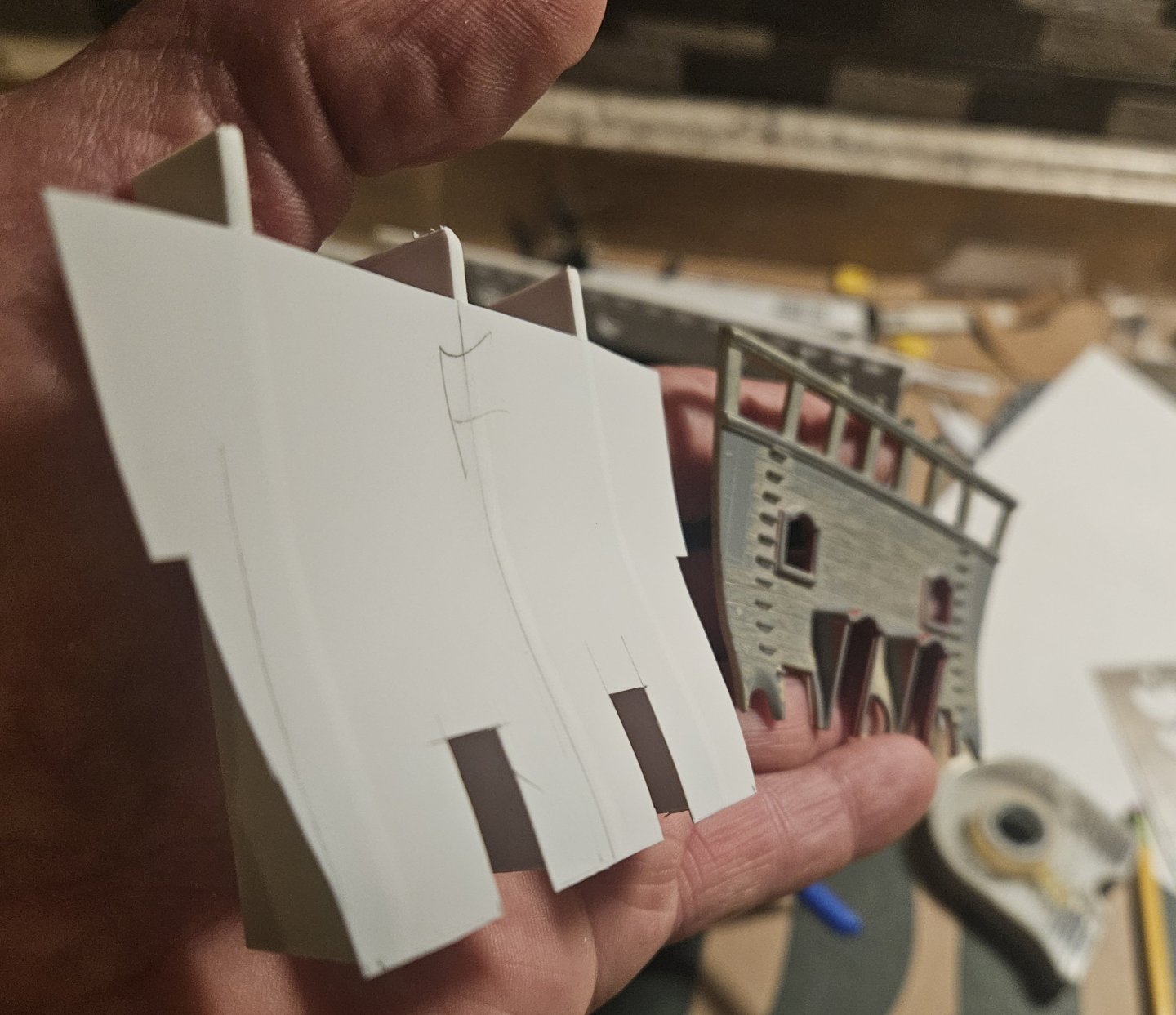
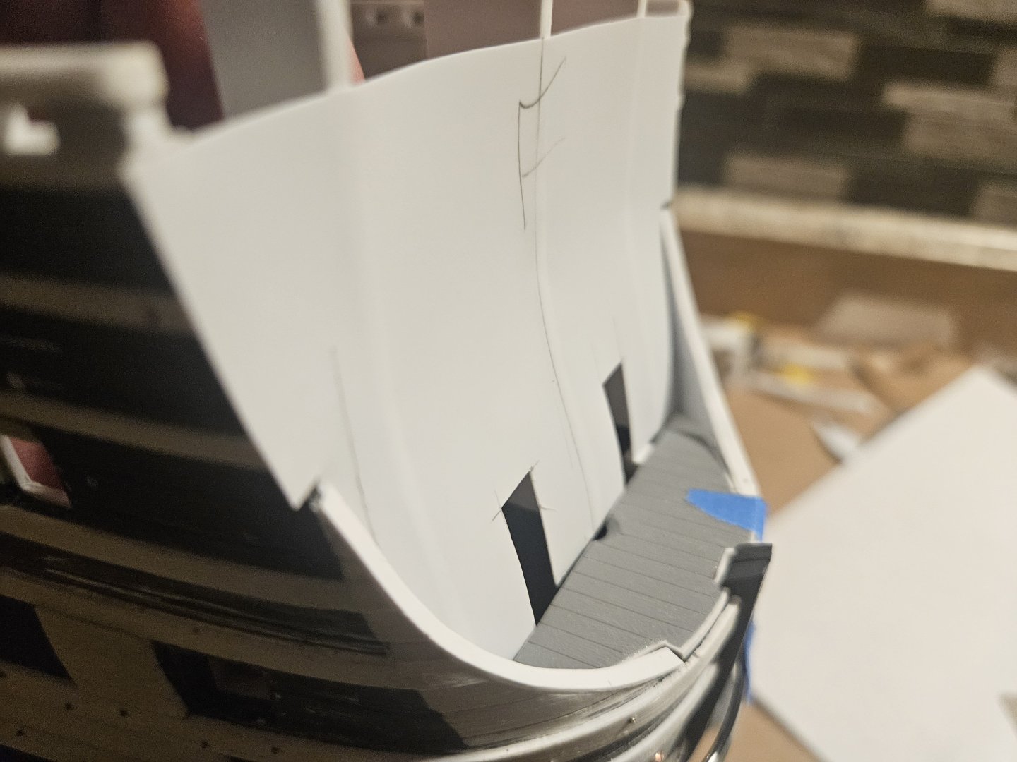
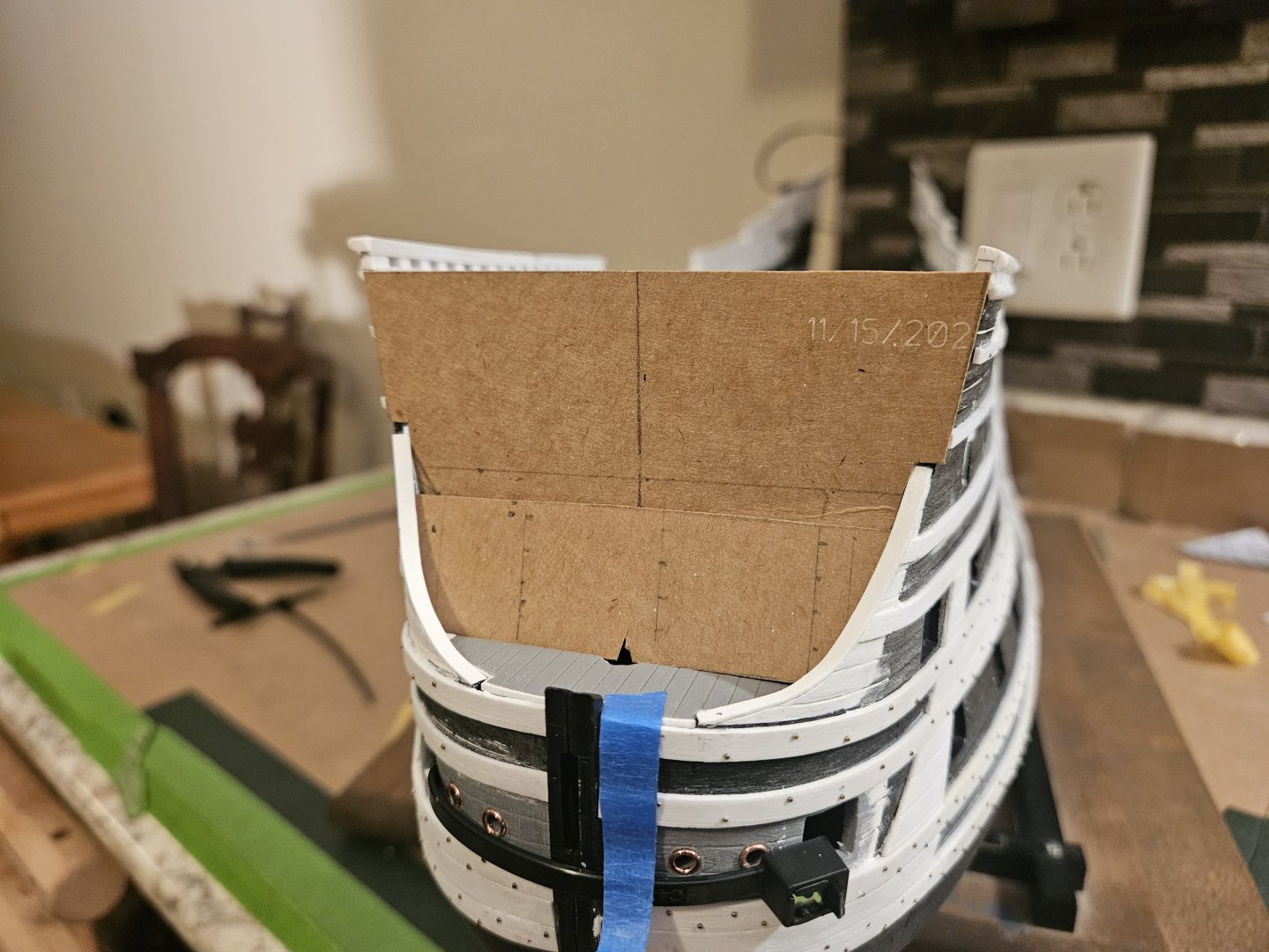
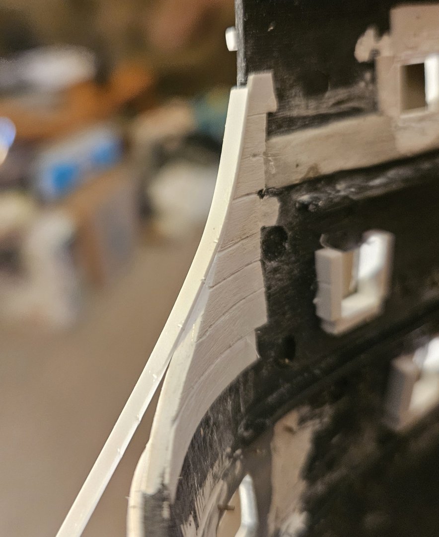
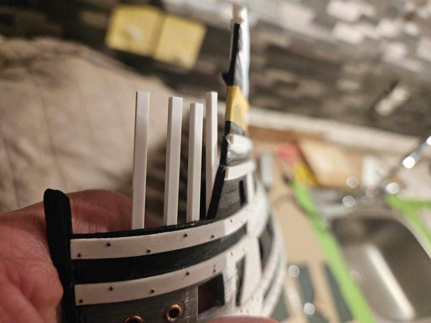
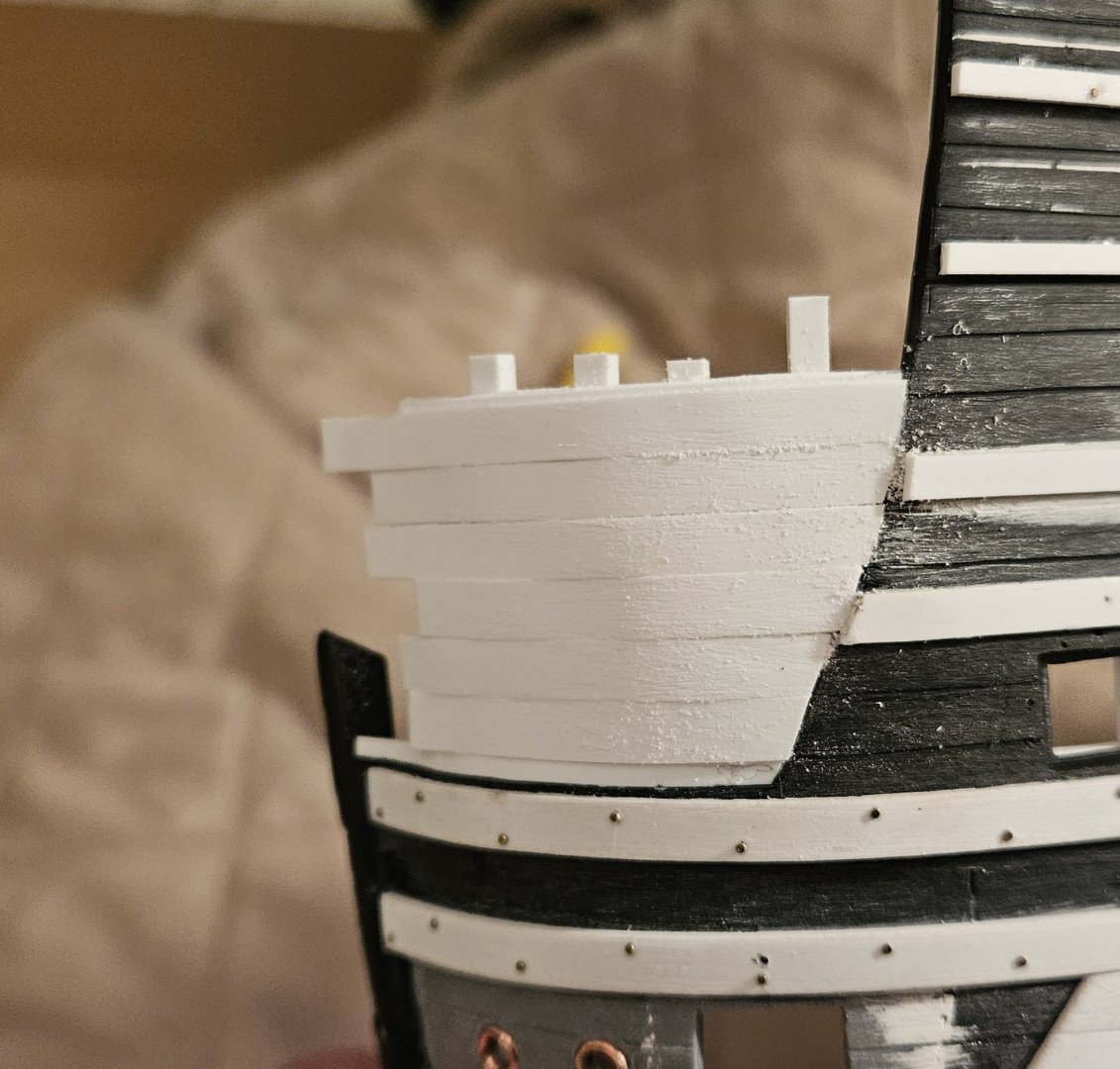
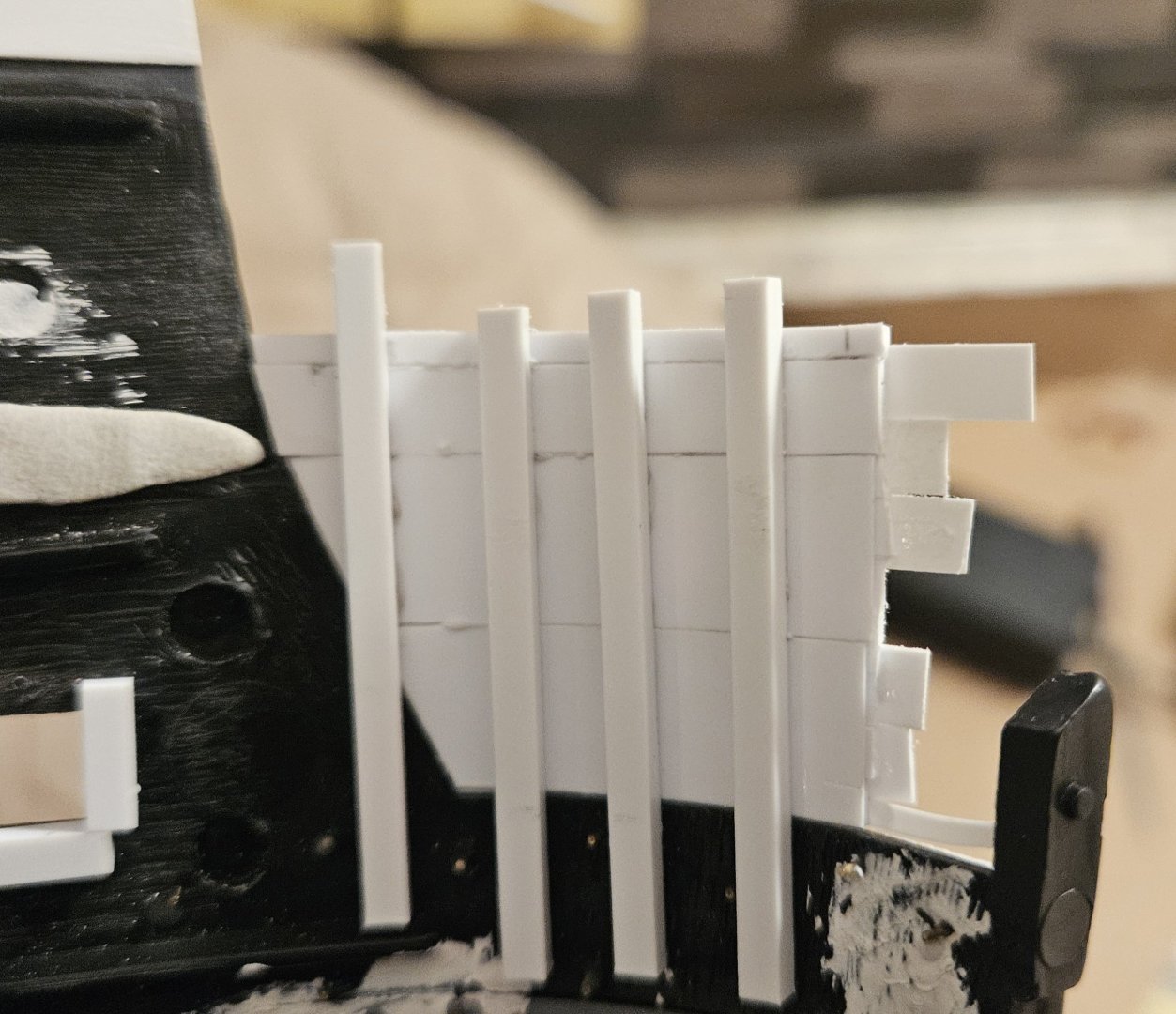
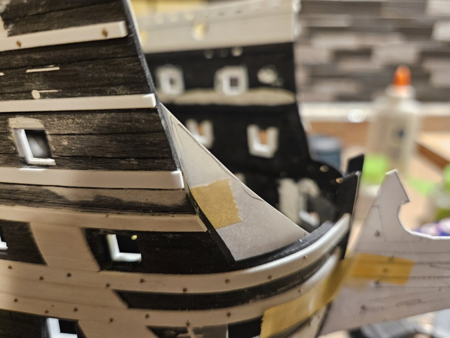
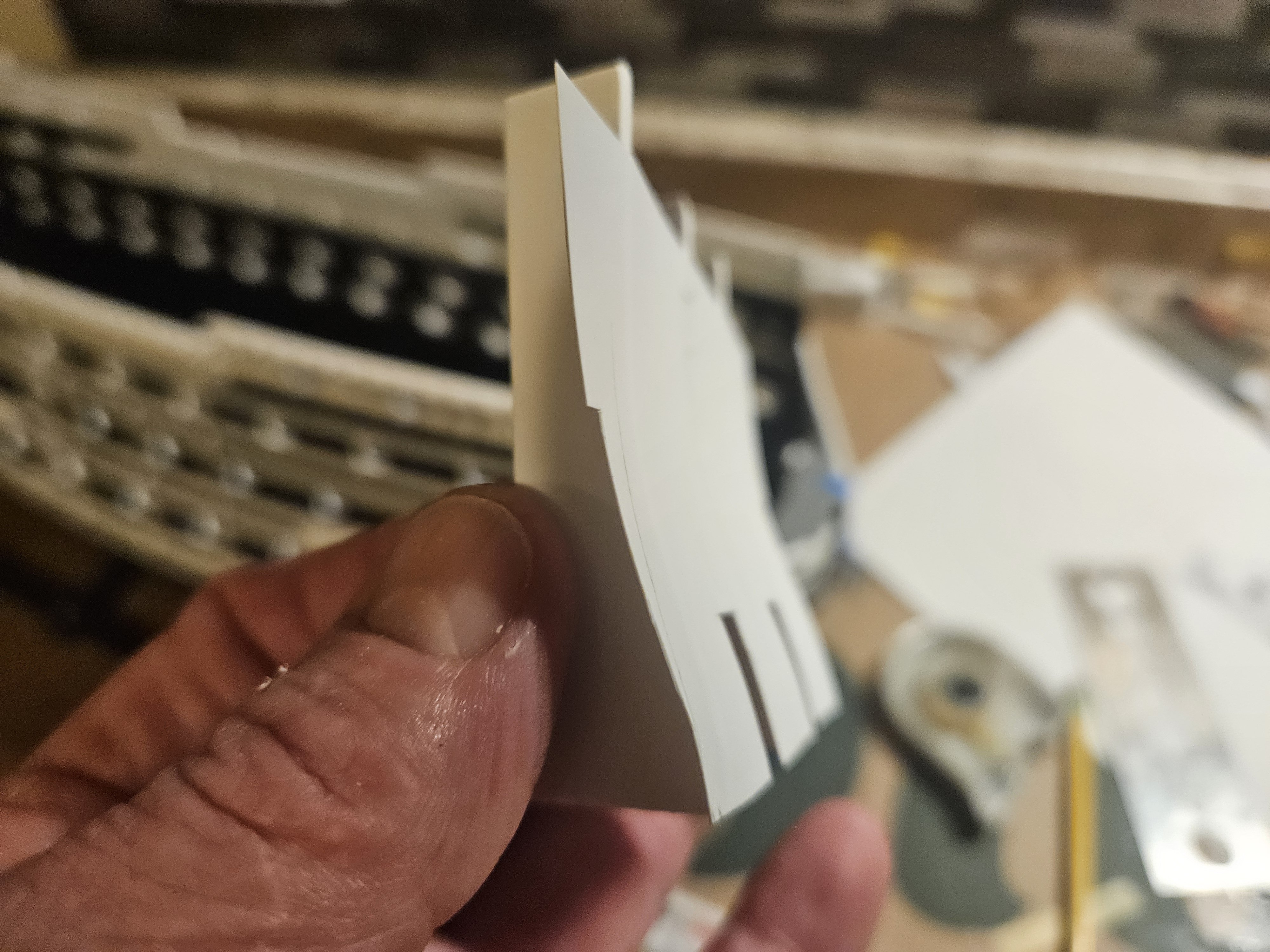
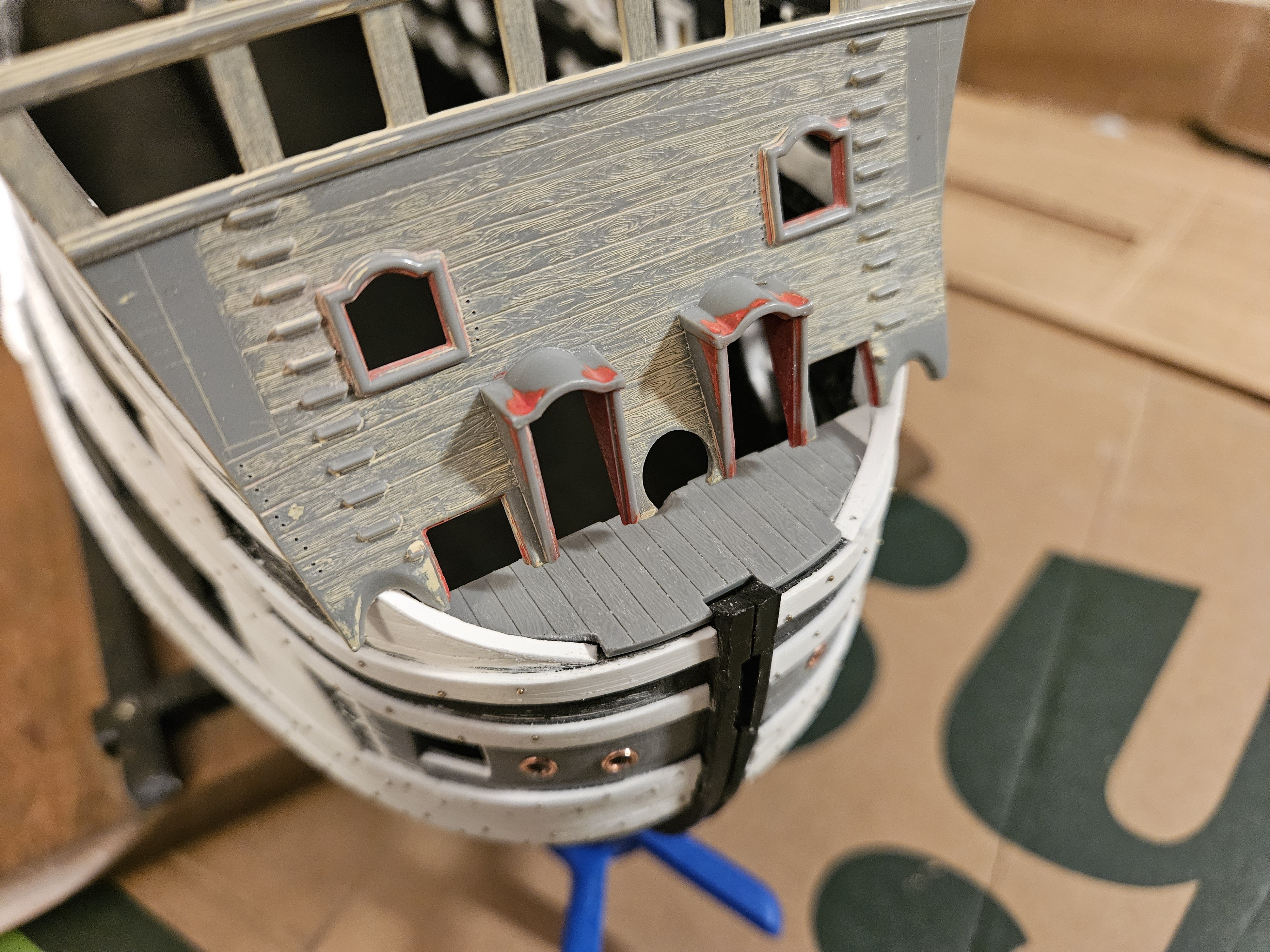
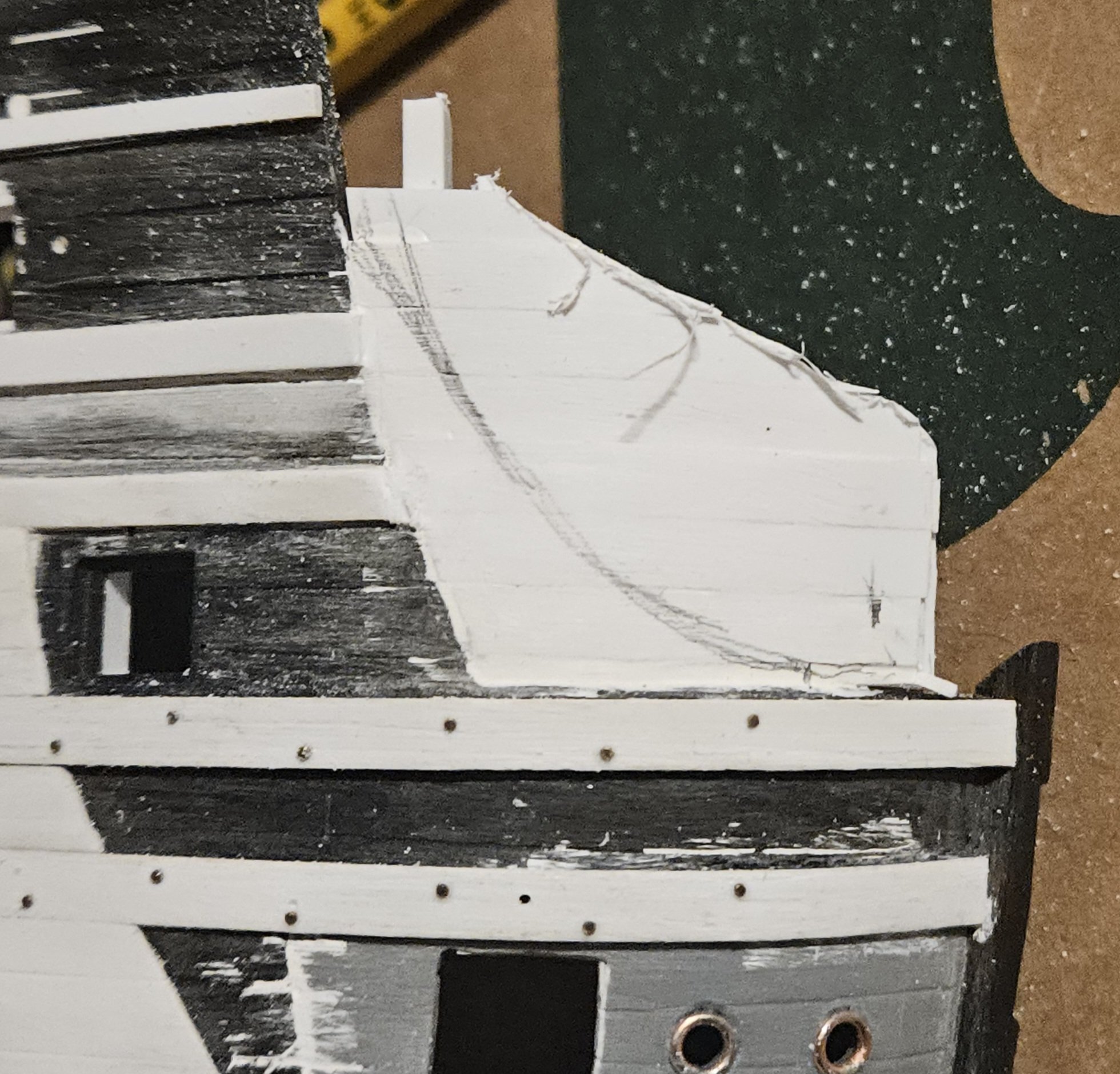
A big exhale, as it appears that the concept I have for the beakhead bulkhead might actually work. First, I went through several iterations of a card template to find a design that fit in with the bulwark "cheeks" (extensions). The next step was create an S-curve side profile for the beakhead bulkhead. I basically used the kit bulkhead S-curve; as Marc LaGuardia has observed though, Dutch ships often had a slight bulge (baby bump?) forward at the bottom of the bulkhead, upwards to about halfway up the height of the door before it started curving aft again.. note the dotted line. The look is subtle, and I tried to keep it minimal. We shall see. The next step was to use that paper contour to develop three 2mm thick ribs that that styrene bulkhead would be glued to and thus the bulkhead would assume that S-curve profile. Again, the ribs basically match the kit S-profile, except for the very small bulge at the base of each rib. I used 0.25mm thick styrene sheet for the bulkead, as I figured that paper thin styrene would follow the contours of the ribs much easier than thicker styrene sheet. I can easily bulk up the bulkhead with additional strips on the inside where no one will see. All three ribs are glued on to the bulkhead... of course, much of the rib structure will be wasted away by my Dremel. Finally, the bulkhead simply laying in place.. Now the real fun starts. I will NOT create two gun ports at the bowsprit deck level... with my bulwark cheek extensions wrapping around, they would be useless. I may put two gun ports on the next deck up, the upper gun deck. Finally, I am also leaning towards four forward facing circular gun ports on the quarter deck, though I don't see a need to arm them. Oh - since my catheads will not be laying on the quarter deck, there will also be no interference there (the catheads will be attached to the bottom of the quarter deck beams). Finally, I will plank the bulkhead. Pretty sure that I will use clinker planking (where the planks overlap), as Marc has noted that this seems to be another characteristic of the Dutch... a possible reason for this mught be that clinker planking would be more waterproof than carvel planking in a location like the beakhead bulkhead.

- 432 replies
-
- 4
-

-
- soleil royal
- Heller
- (and 1 more)
-
The beakhead bulkhead. I made a number of measurements, and have cut several cardboard templates this morning. I am in no rush these next few days. It makes sense to simply look at the cardboard templates off and on for several days and and think "what could go wrong here..."? I am leaning towards using 1mm thick sheet for the bulkhead... 2mm seems way to thick and harder too work with.

- 432 replies
-
- 3
-
-
- soleil royal
- Heller
- (and 1 more)
-
That is a good reminder! I have NOT sanded those surfaces yet, but I will do that.
- 432 replies
-
- 1
-
-
- soleil royal
- Heller
- (and 1 more)
-
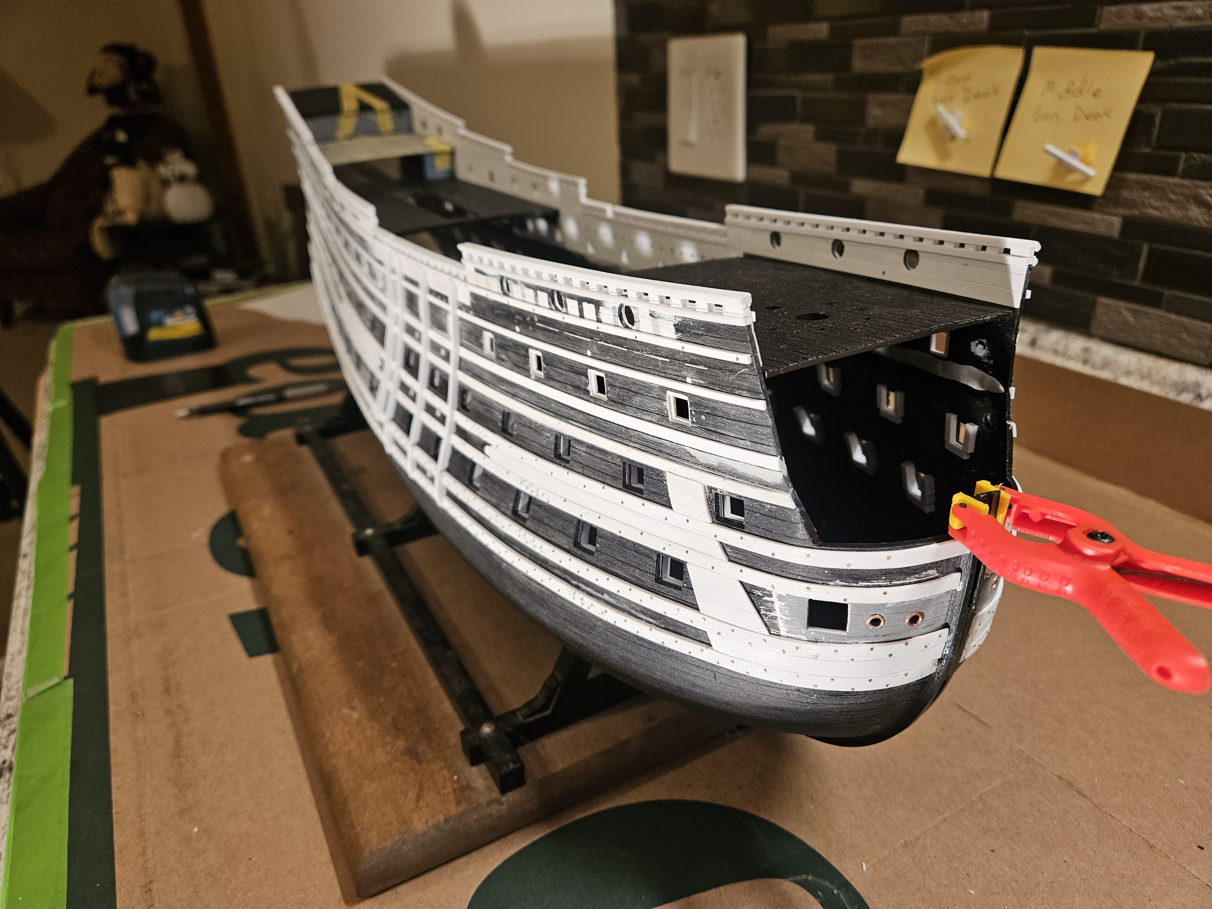
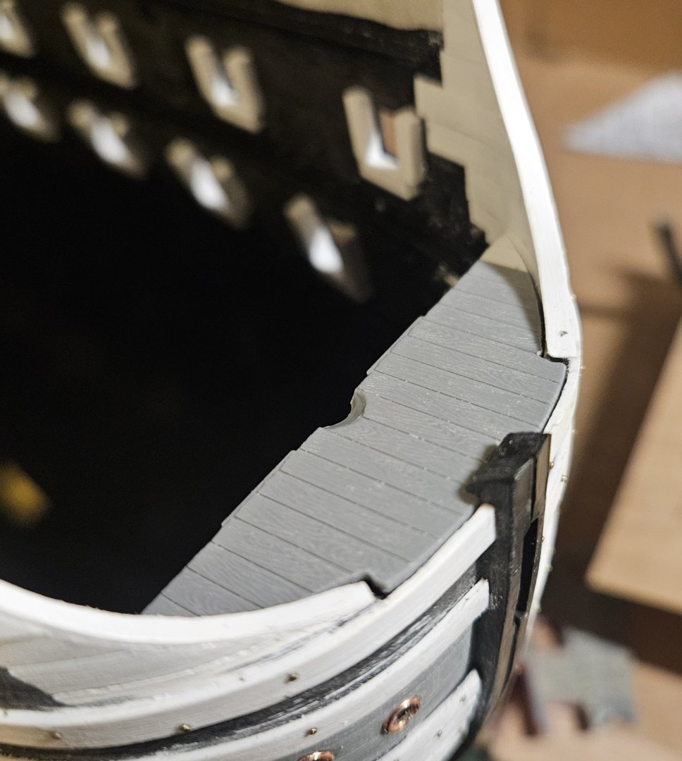
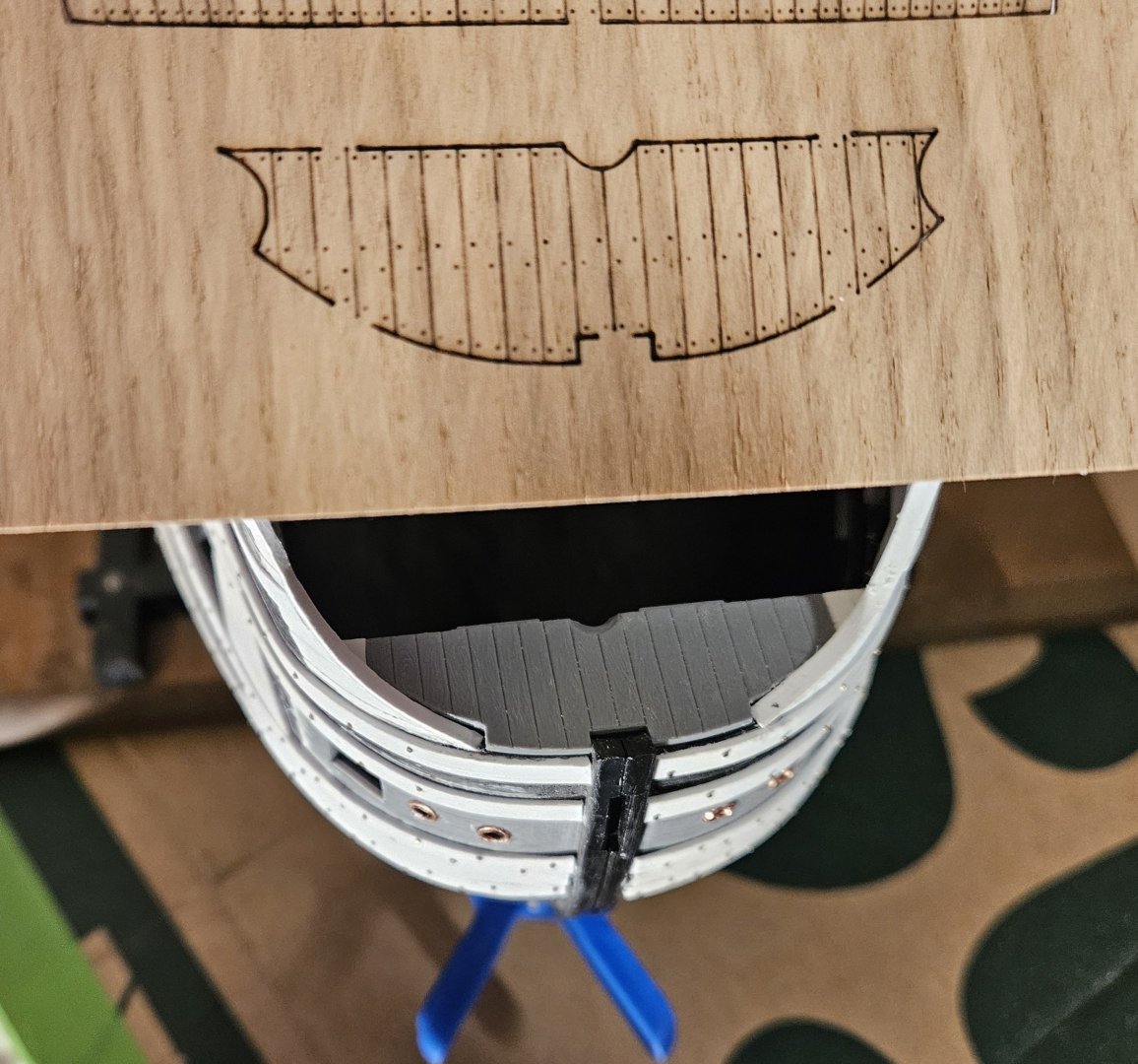
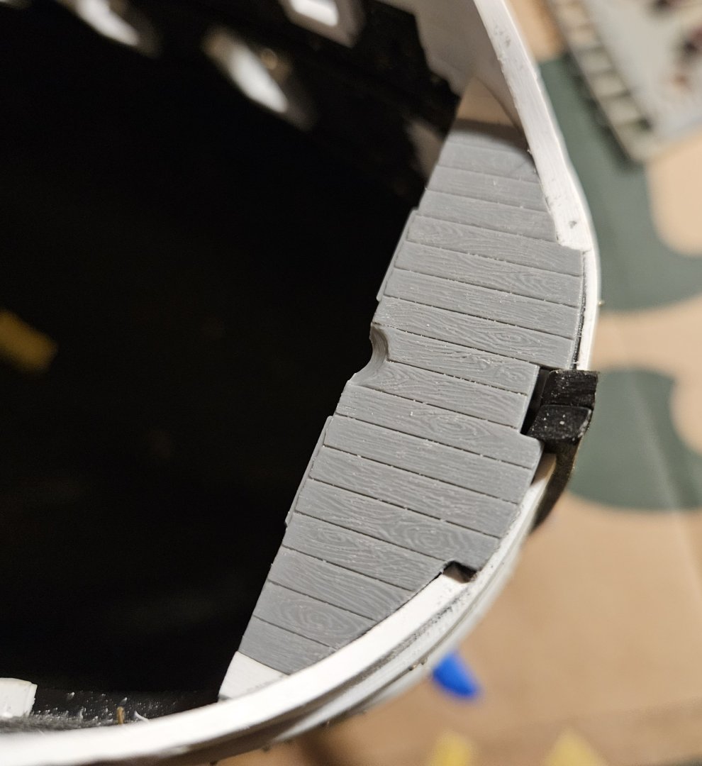
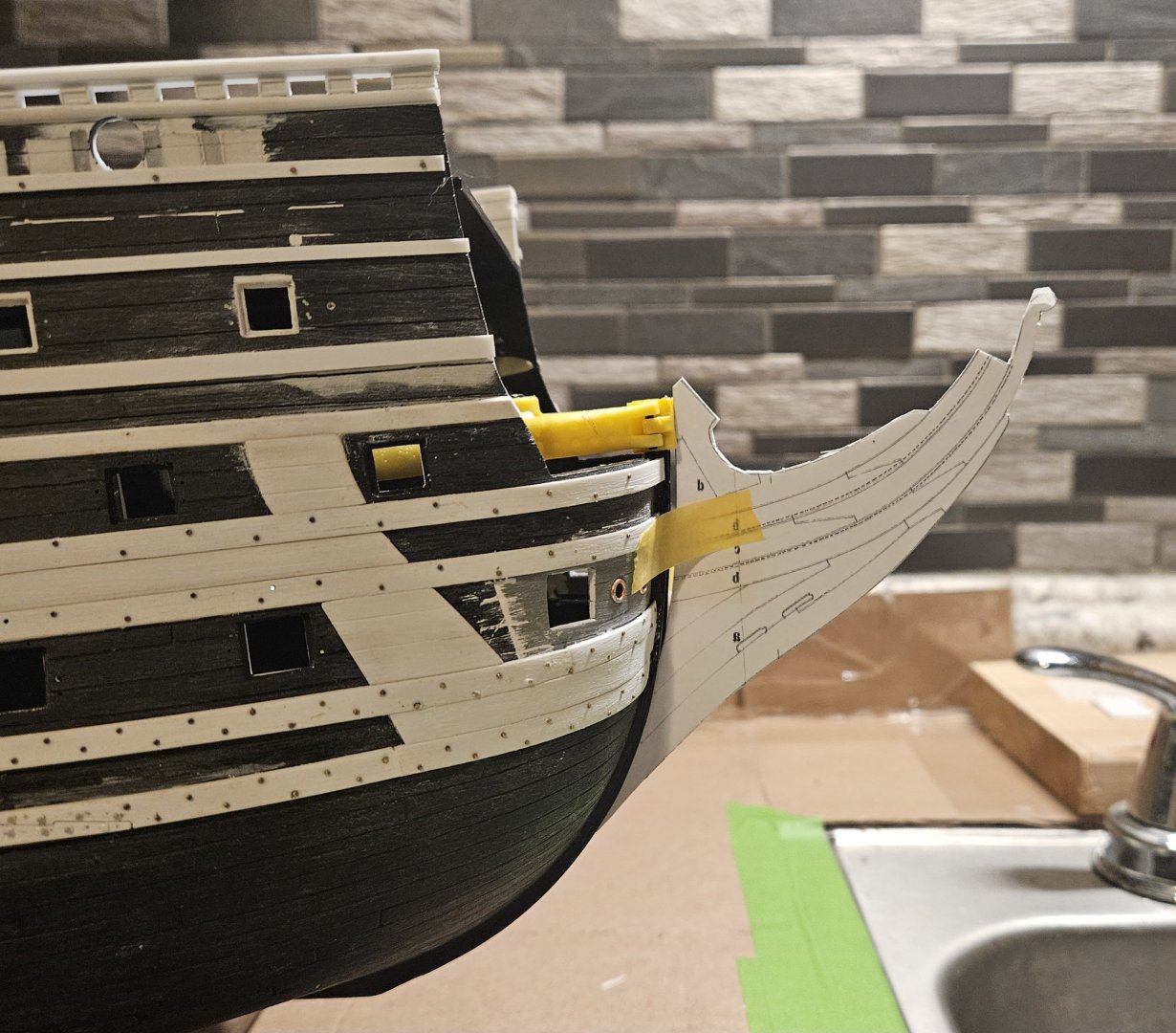
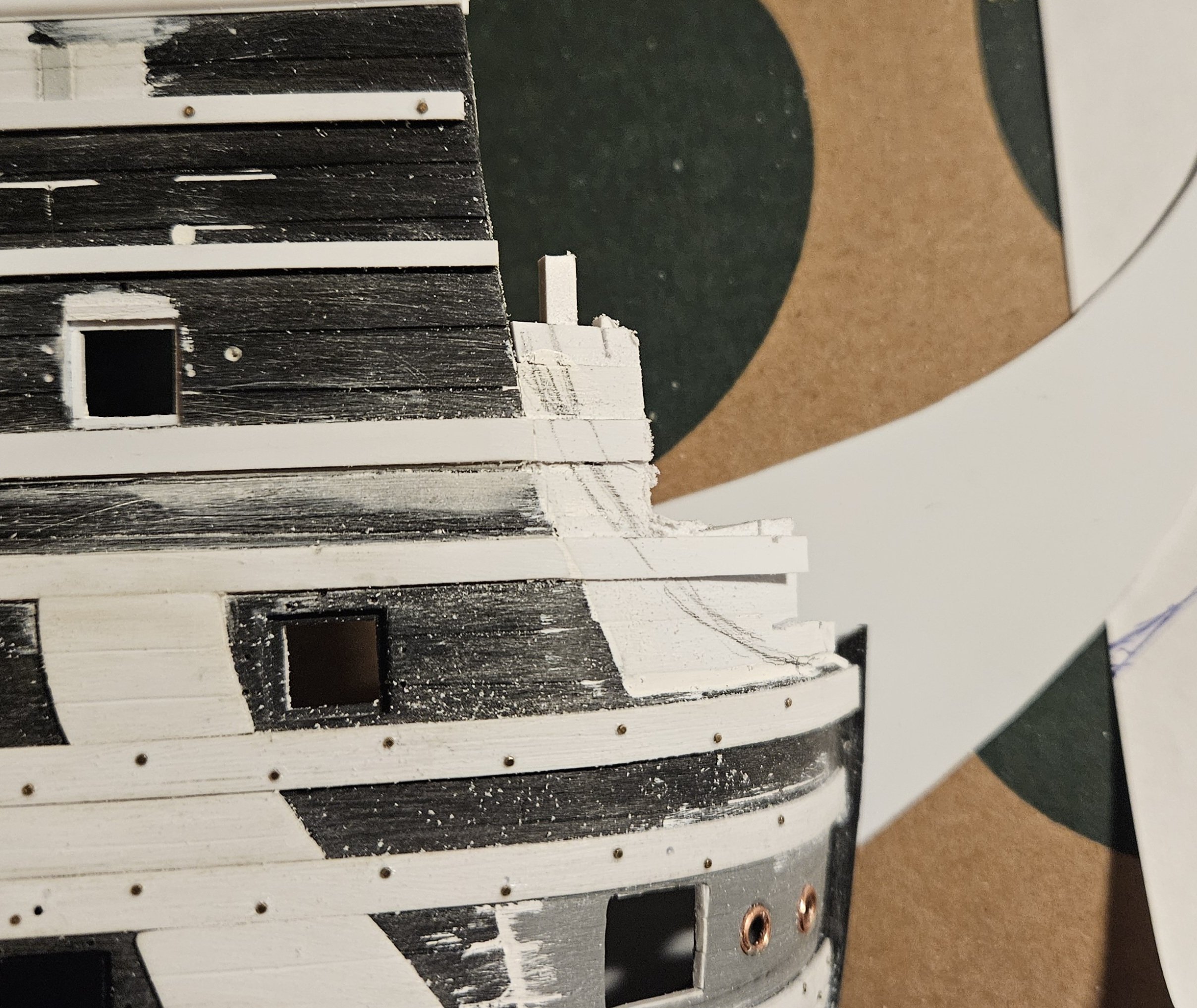
As per Marc's suggestion, I cut two rebates in the ledge that supports the forward edge of the bowsprit deck. FYI... you may notice one of the three additional white locking pins that I added to the stem, as I felt that with all of my add-on work, the stem connection needed to be more robust. And the bowsprit deck now snuggles in (the fit is actually very tight - in this picture, the deck is just sitting there with no downward pressure). i have a friend making a wooden bowsprit mast for me on a lathe; he actually made a precise jig that will allow him to taper the mast to my target diameters (based on the St Phillipe monograph). If this works, all of my masts will eventually be made of wood. In the meantime, on to creating the beakhead bulkhead and the overall head structure.

- 432 replies
-
- 4
-
-
- soleil royal
- Heller
- (and 1 more)
-
Ahh, that makes a lot of sense.... the rebate will allow the bowsprit deck to drop 1-2mm and be hidden by the edge of the wale... which is just what I am seeing on some models!
- 432 replies
-
- 1
-
-
- soleil royal
- Heller
- (and 1 more)
-
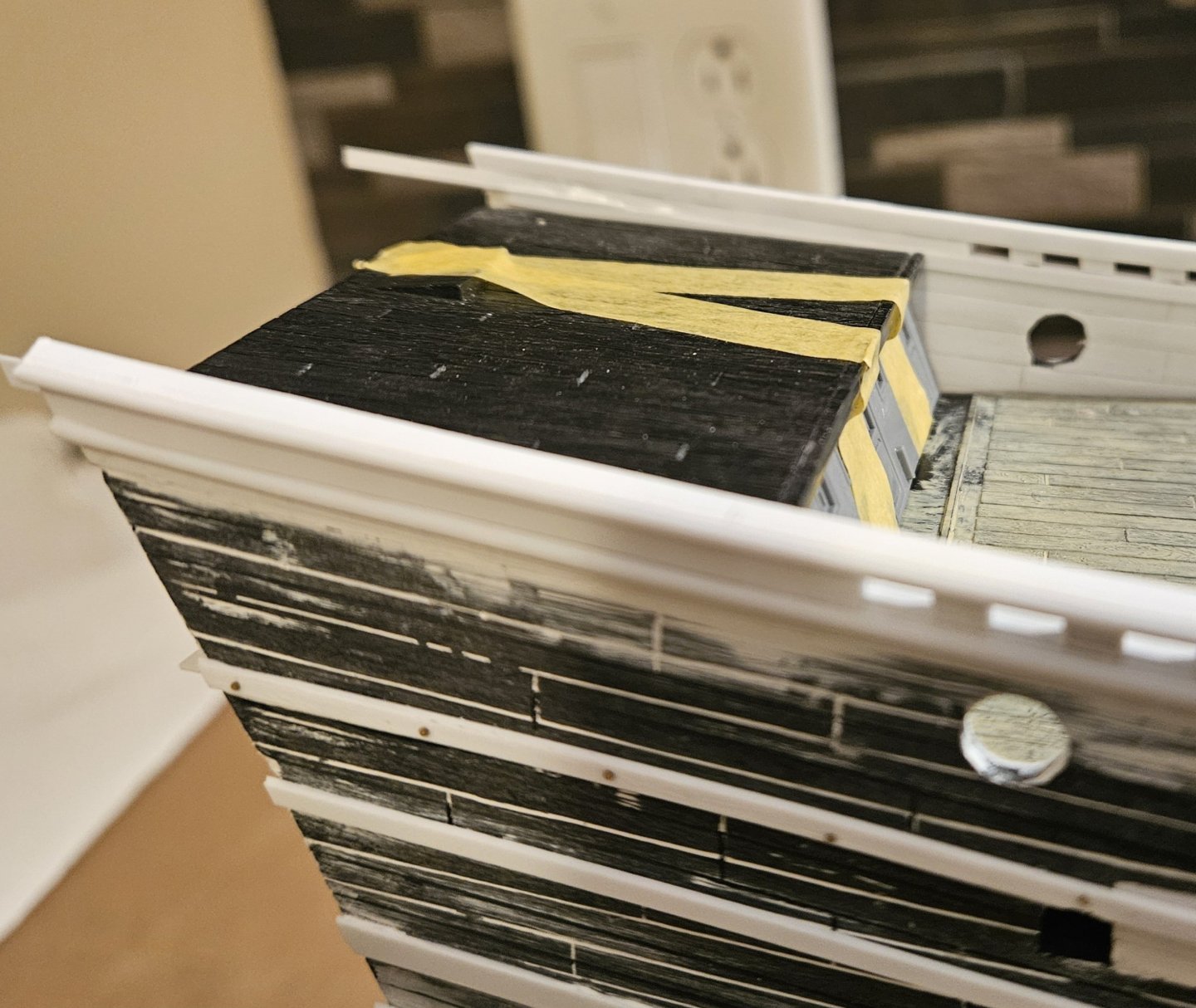
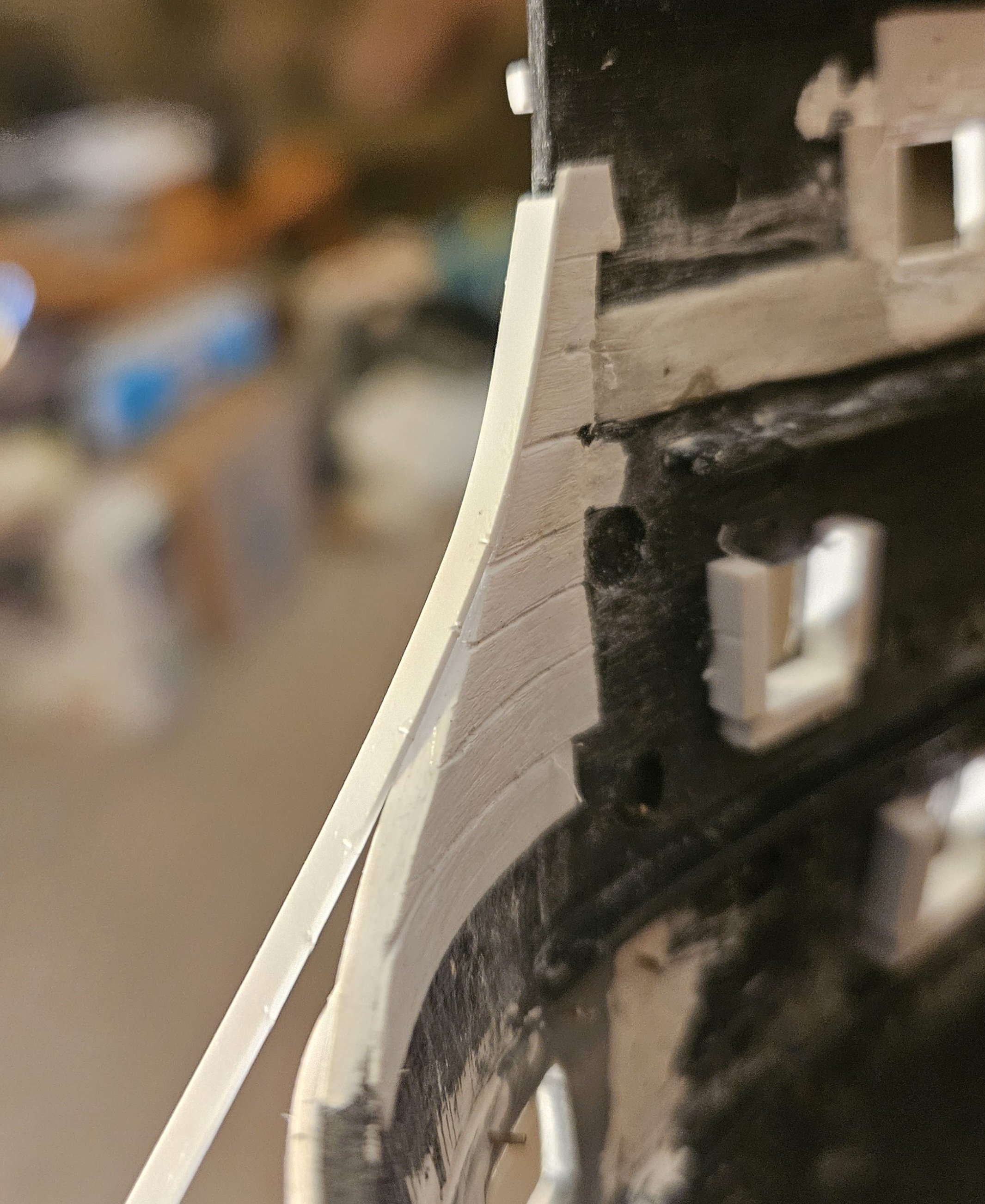
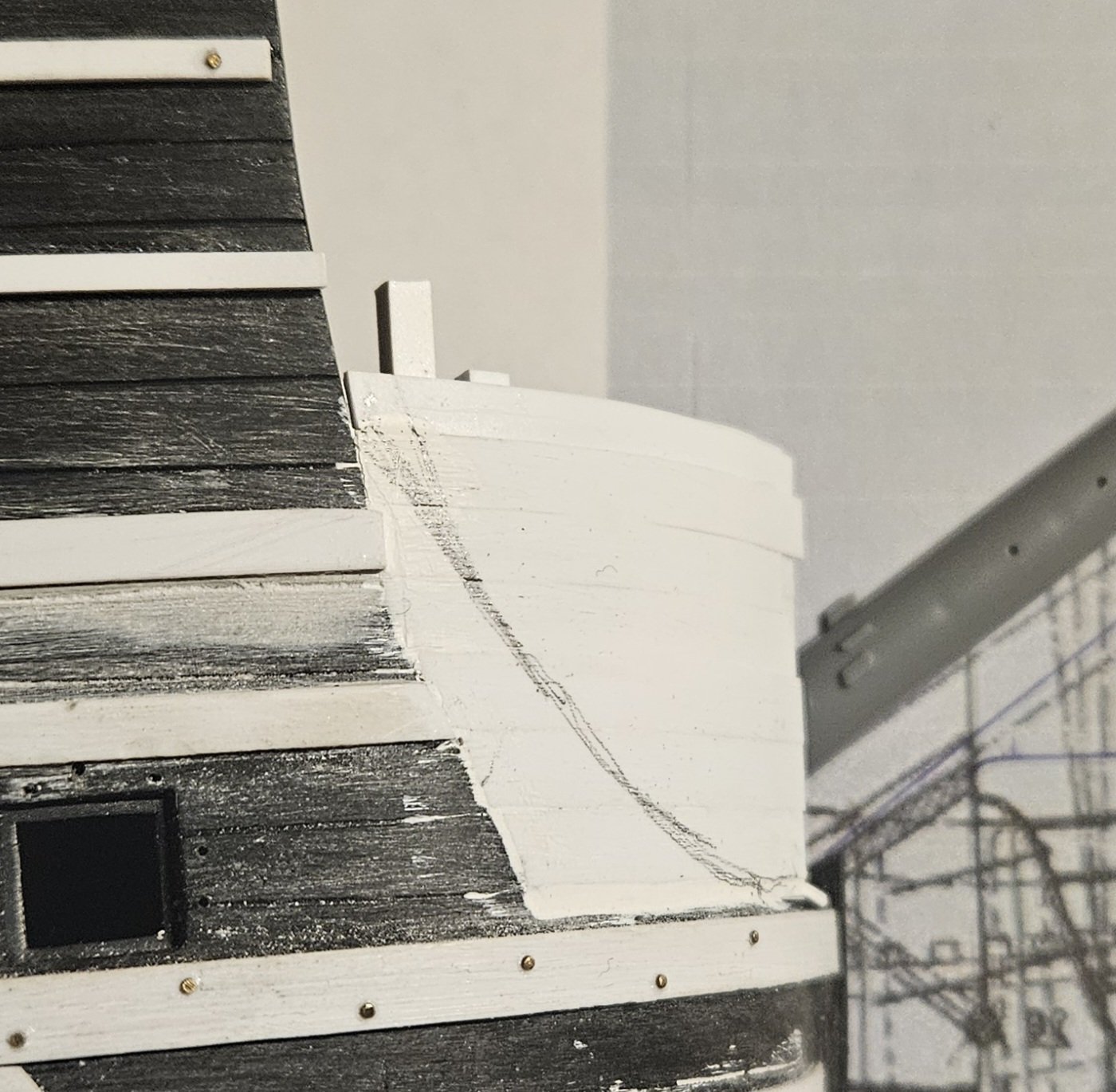
The forward bulwark cheeks are essentially done. I will study other models/drawings to see if there is any trim or anything else to finish off the cheeks, but the plank scribing is done inside/out. The bowsprit deck has been trimmed to fit the new cheeks, and I laid the beakhead bulwark on for a sense of what it will look like; of course, I am going to fabricate a completely new beakhead bulwark that fits inside the forward bulwarks (as opposed to overlapping the front edges of the beakhead bulwarks). I have to figure out how they would have the downward sweep of the cheeks meet the bowsprit deck. Big picture, I think I will construct the head and head rails now as far as I can go, just to ensure precise fit after the hulls are painted and glued. A year ago, I got a replacement wooden deck kit for SR... I really do like the detail and figured it would save me plenty of time that would be spent painting the original deck. But first... I have to figure out exactly where the bowsprit would go through the bowsprit deck in order to maintain my 37 degree bowsprit steeve that I need for the overall head design. In fact, I am now thinking that I may also construct the new beakhead bulkhead in advance, as well as the overall head and head rails. It's funny, as every decision like this seems like "one step forward, two steps back" in regards to painting the hull. However, as Marc LaGuardia has observed, "a large project is just a lot of smaller projects!..". So it seems logical to me the more of these subassemblies that I get done now - and I can verify precise fit and appearance - the easier my life will be down the road in a few months.


- 432 replies
-
- 3
-

-
-
- soleil royal
- Heller
- (and 1 more)
-
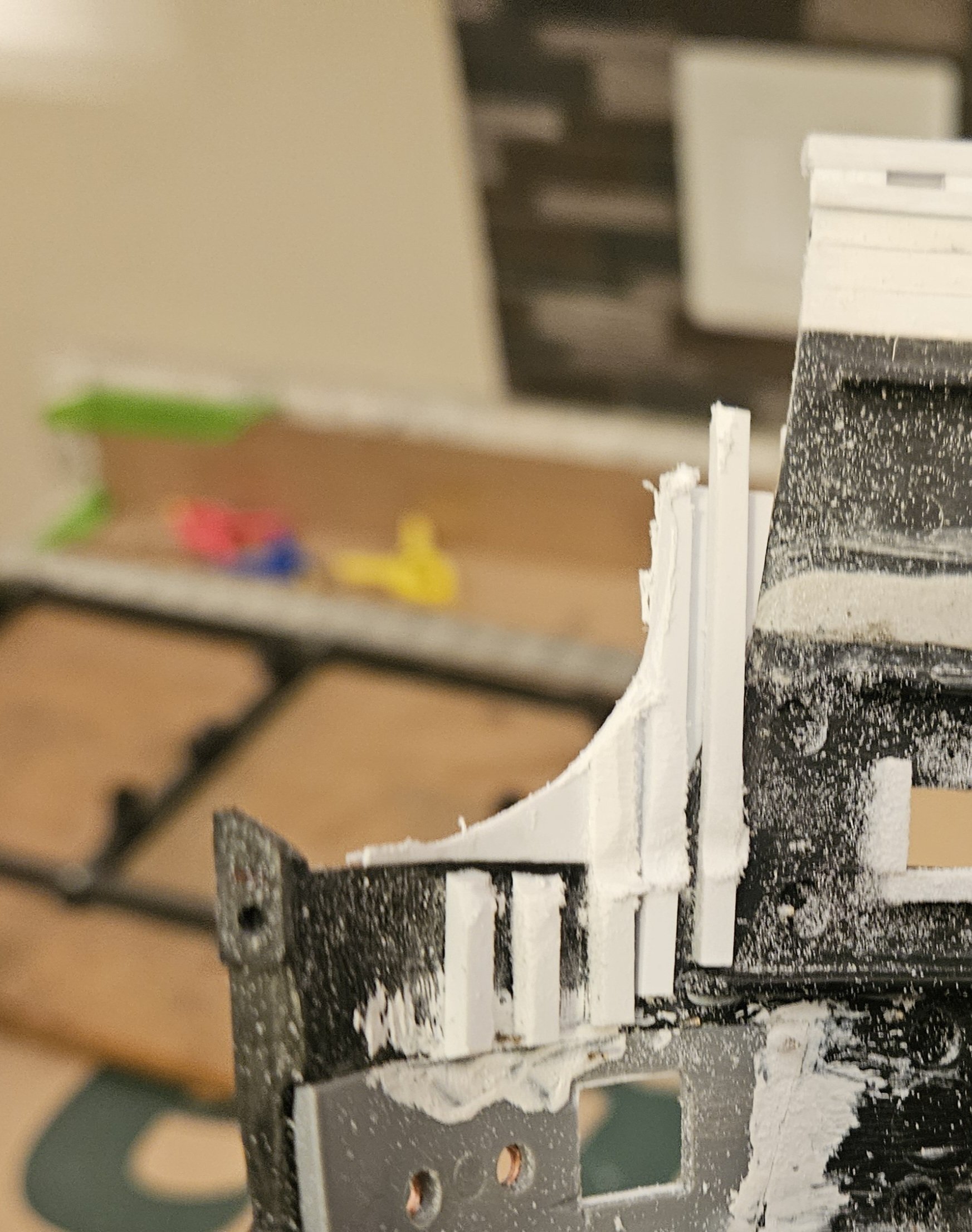
The starboard cheek is almost done. I tapered/planed the top wale thickness down as they wrap the cheek as I see on the St Phillipe monograph (I assume they tapered in thickness to easier bend around the round bow?). I finished off the top of the cheek with a plank and scribed the planls inside/out. Next step is to continue wasting away the port cheek so that I scribe the planks and apply a plank on top (cap).


- 432 replies
-
- 5
-
-
- soleil royal
- Heller
- (and 1 more)
-
The starboard forward bulwark extension (cheek?) is almost done... ready for a bit of needle file work then planking on the inside. I am surpised at hoiw subtle it is, but it has to be this way to follow the edge of the top head rail. The first step, of course, was settling on a head design, and then I was able to create a head rail design (note that the middle and bottom head rails will NOT join the top head rail in a rosette at the forwqrd bulwark/cathead area... they will be feyed into the hull). Then it was a relatively simple matter of wasting away with the Dremel.... Now it is just a clean up and making sure the plank lines are clean, etc. Again, I envisaged the cheeks as being much larger in appearance, but given the immutable lines of the hull and the head rail curve that they must follow, the actual cheek is small (to me eyes). However, this matches up with what I see on the St. Phillipe monograph and some drawings. Marc LaGuardia had suggested having vertical framing pieces glued to the inside of the hull to attach the outer planks to... and then waste them away and plank over them on the inside. This was my only concern going in, but it turns out the cheek extension is actually very sturdy, even without the vertical framing pieces.


- 432 replies
-
- 4
-
-
- soleil royal
- Heller
- (and 1 more)
-
Interesting drawing.. and great advice on sealing the edges of the template with CA... that really helps!
- 432 replies
-
- 2
-
-
- soleil royal
- Heller
- (and 1 more)
-
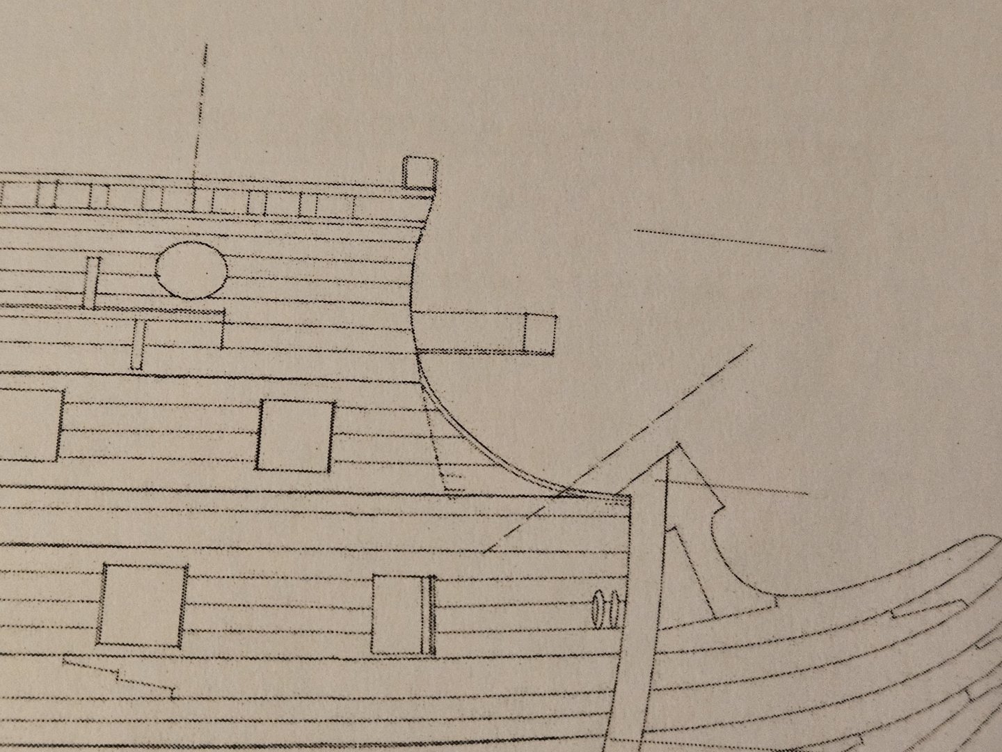
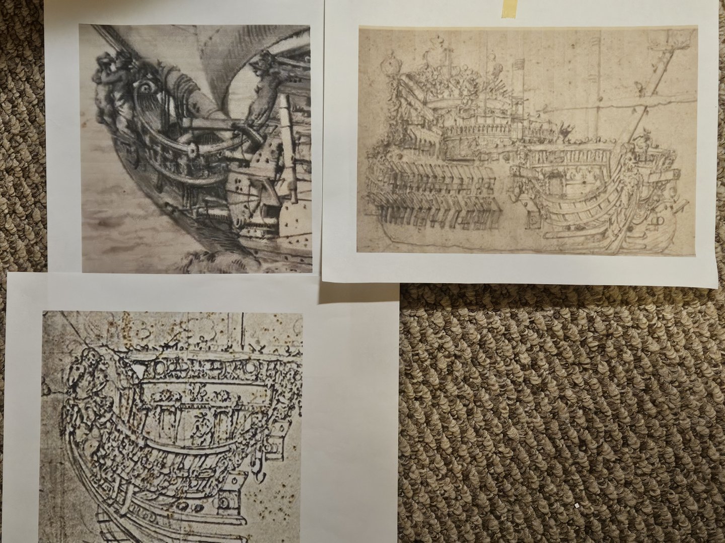
Have spent the last week looking at lots of beakhead drawings and making an equal number of templates. I didn't understand the value of French Curves before this! I want the bow of this SR 1671 to be more "Dutchy" slung a little lower and longer. If I wanted it to look real "Dutchy", I would have made the cutwater almost straight with no upward curve, but... that really looks "Dutchy". I think I am 95% of the way there, as the head rail rosette and figurehead are going to have to creep several millimeters to get in perfect alignment... and that may be months down the road after the hull is painted and glued together. However, I am pretty confident I can start creating the beakhead and head railis from Evergreen styrene now... ohh and the bowsprit steeve was increased to 37 degrees, as the kit is about 32 degrees I will also be able to start "wasting away" the bulwark extensions... I made a rough curve in pencil just to see how it looks. I just laid a pencil on the head rail template and made a line... I am wondering if there is a technique where I can create a nice line on the bulwark as it curls away from the template? Maybe I could shine a very bright light at the head rail and trace the shadow? Finally, I saw this gorgeous Soleil Royal figurehead, and wanted to emulate the open areas where the tail of the merhorse is, so I am cutting and filing away the kit knee that the figurehead wraps around. I will be much happier. To sum up the last week... a lot has happened.. but you couldn't tell it by looking at the ship!


- 432 replies
-
- 3
-
-
-
- soleil royal
- Heller
- (and 1 more)
-
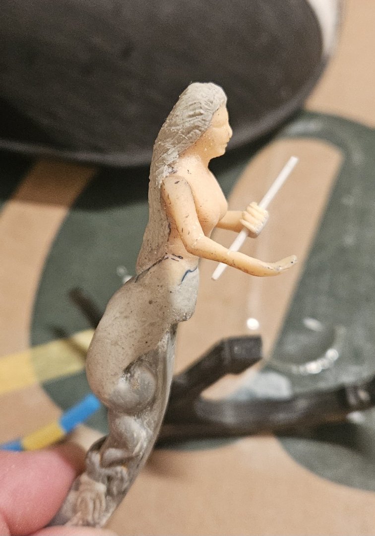
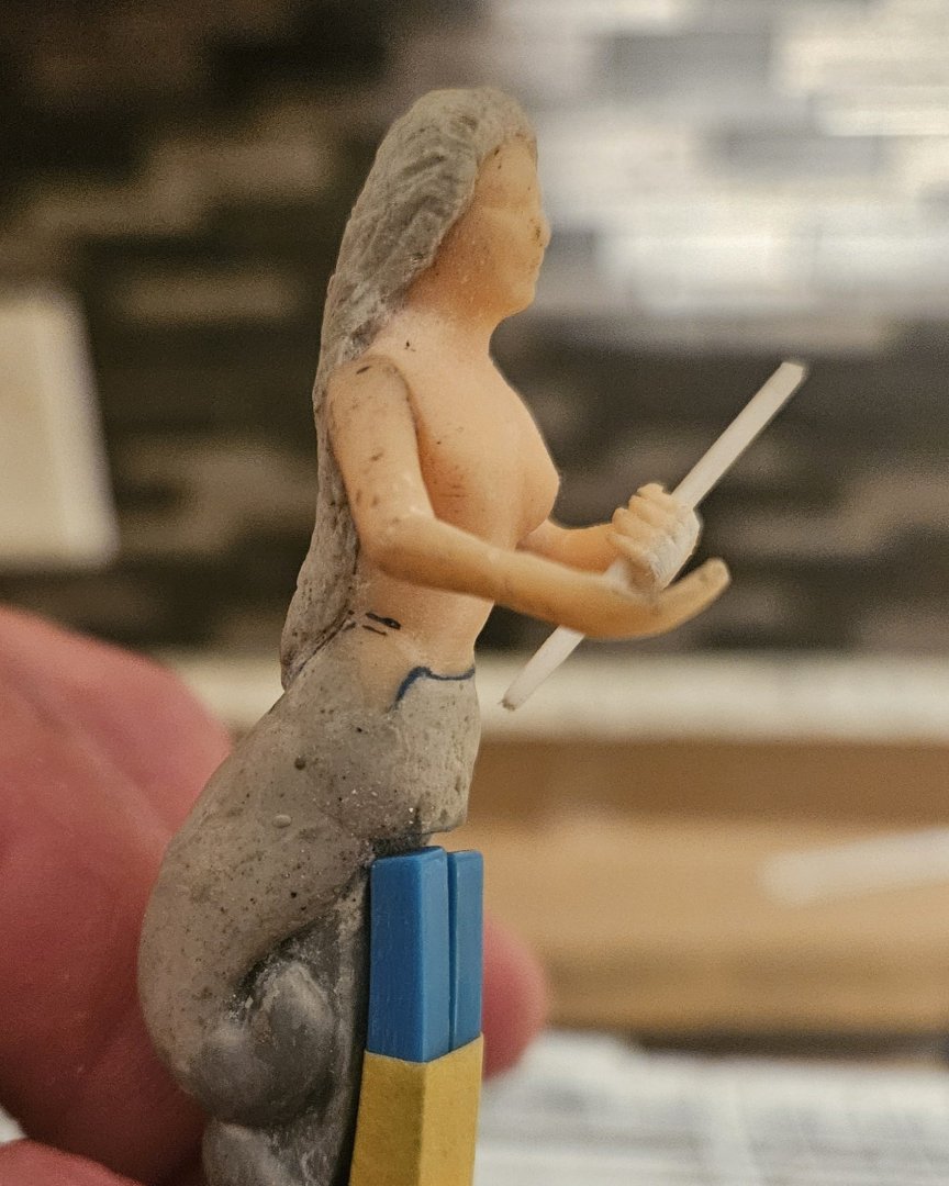
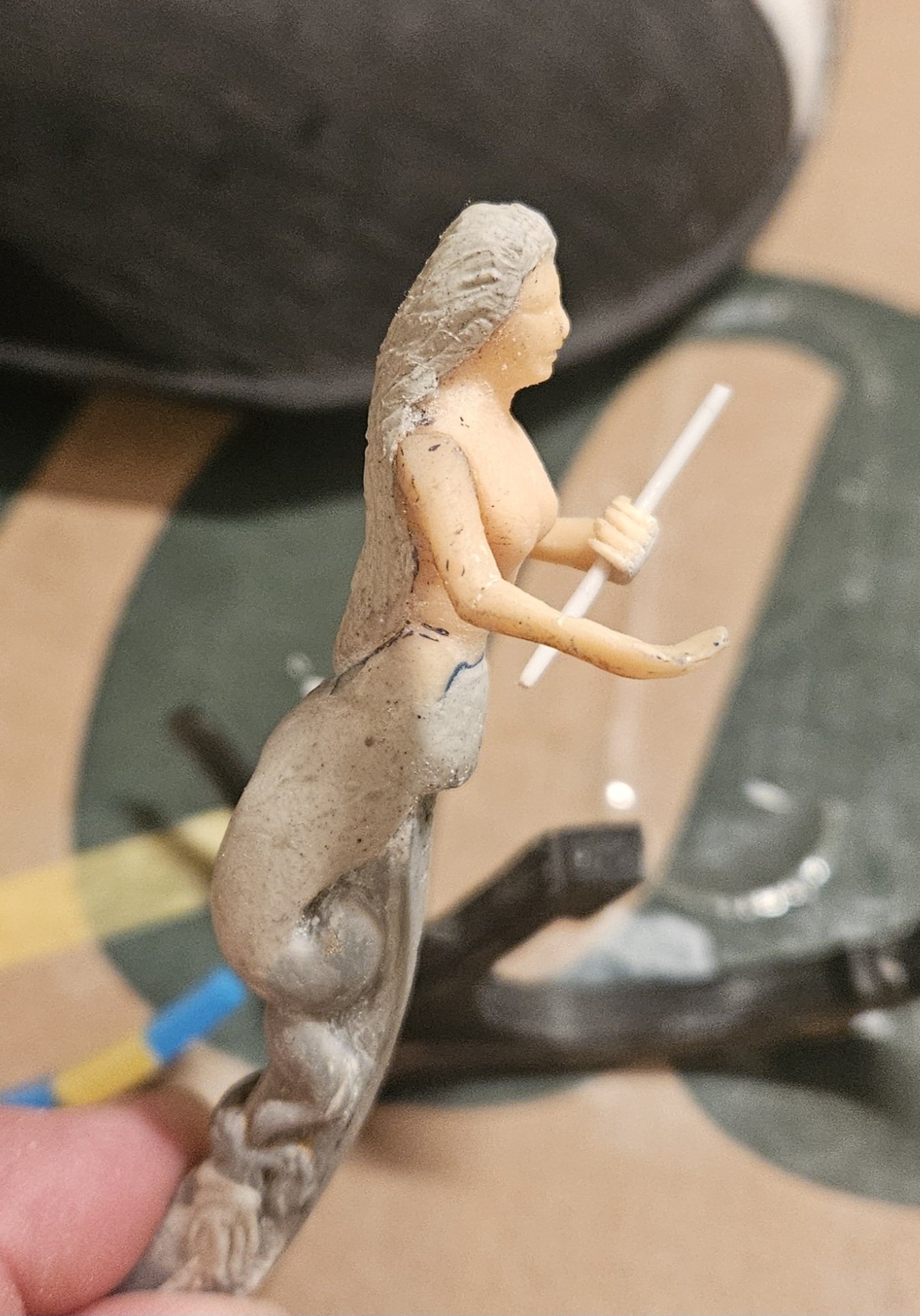
Well, she is almost done. Needs a bit of work to fill in the shoulders, and then a wash. Of course, I have to finish the scepter and install the globe/crown... I am NOT going to strive for clinical anatomical precision, so her body is done. I did manage to graft a left thumb on - feying and applying that thumb felt like I was really doing surgery. Technically, this has been a 3 day project, but the reality is that it was only 2-3 hours a day, with plenty of drying down allowed. My French Curves arrived, so now I can get to work designing and fabricating the head.
- 432 replies
-
- 4
-
-
-
- soleil royal
- Heller
- (and 1 more)
-
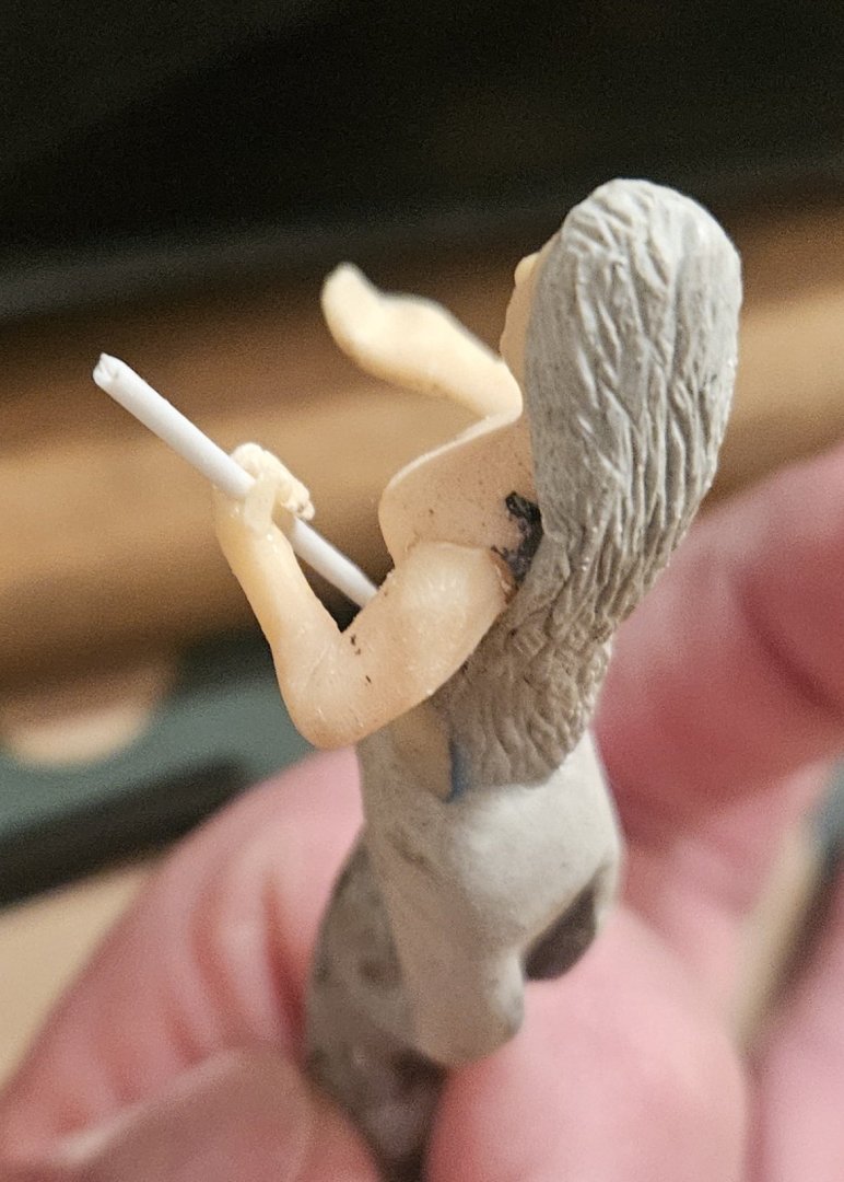
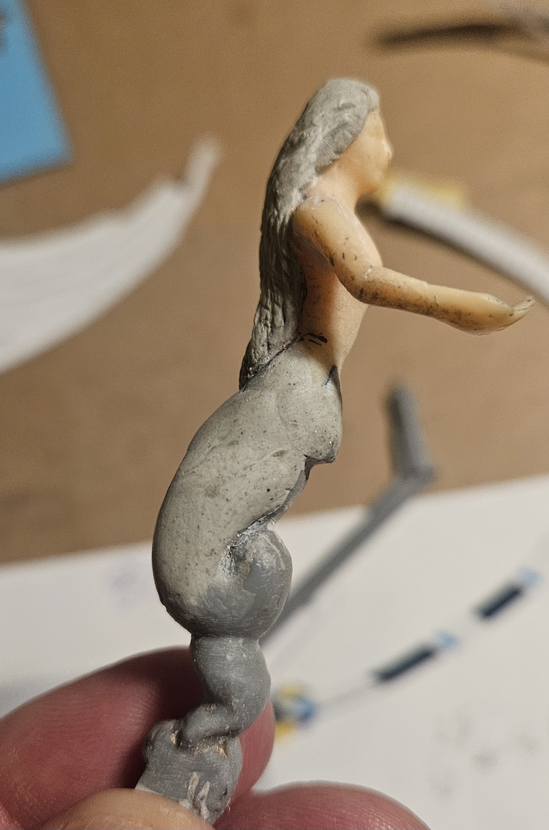
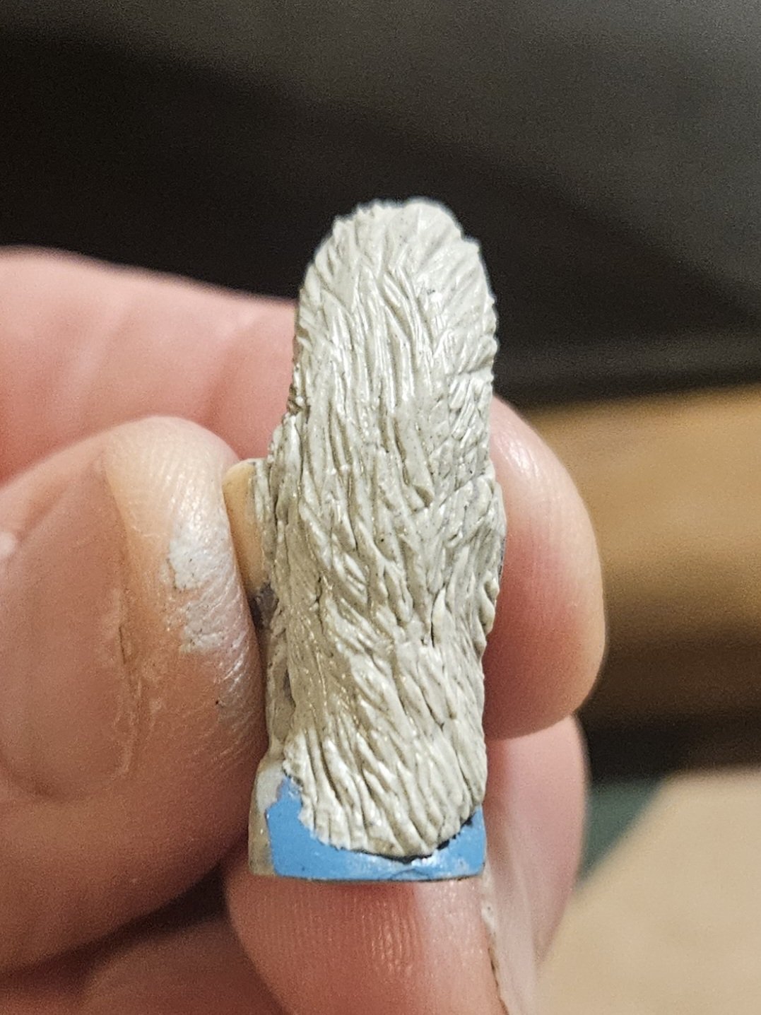
I took Marc's advice to heart regarding carving some "movement" into her hair. Except, I realized there wasn't enough plastic mass on her head to carve into a flowing mane that cascades down her back... so I gave her a haircut. And got out the ApoxieScuplt. I am much happier with this mane of cascading hair. The only negative is I have to be patient and let her dry for 24 hours. Then I can add her arms and have some tendrils of hair come down across her chest. I used loops of various gauge copper wire to try and lightly press in the texture. I couldn't get finer than 28 gauge to simulate really fine hair, and I found if I dragged a very fine, sharp point - it just gouged a trench. She will look better with a cleaning - I won't win a contest with Doris, but I think she looks better than she did yesterday.


- 432 replies
-
- 5
-
-
-
- soleil royal
- Heller
- (and 1 more)
-
Thank you, Marc.. I will do that. I know on your build log, I can find the part where you mention what carving tools you use. I have no "carving" tools yet.... I am guessing for hair, I would need a tool that I can pull, instead of push? I will go to a local crafts store tomorrow!
-
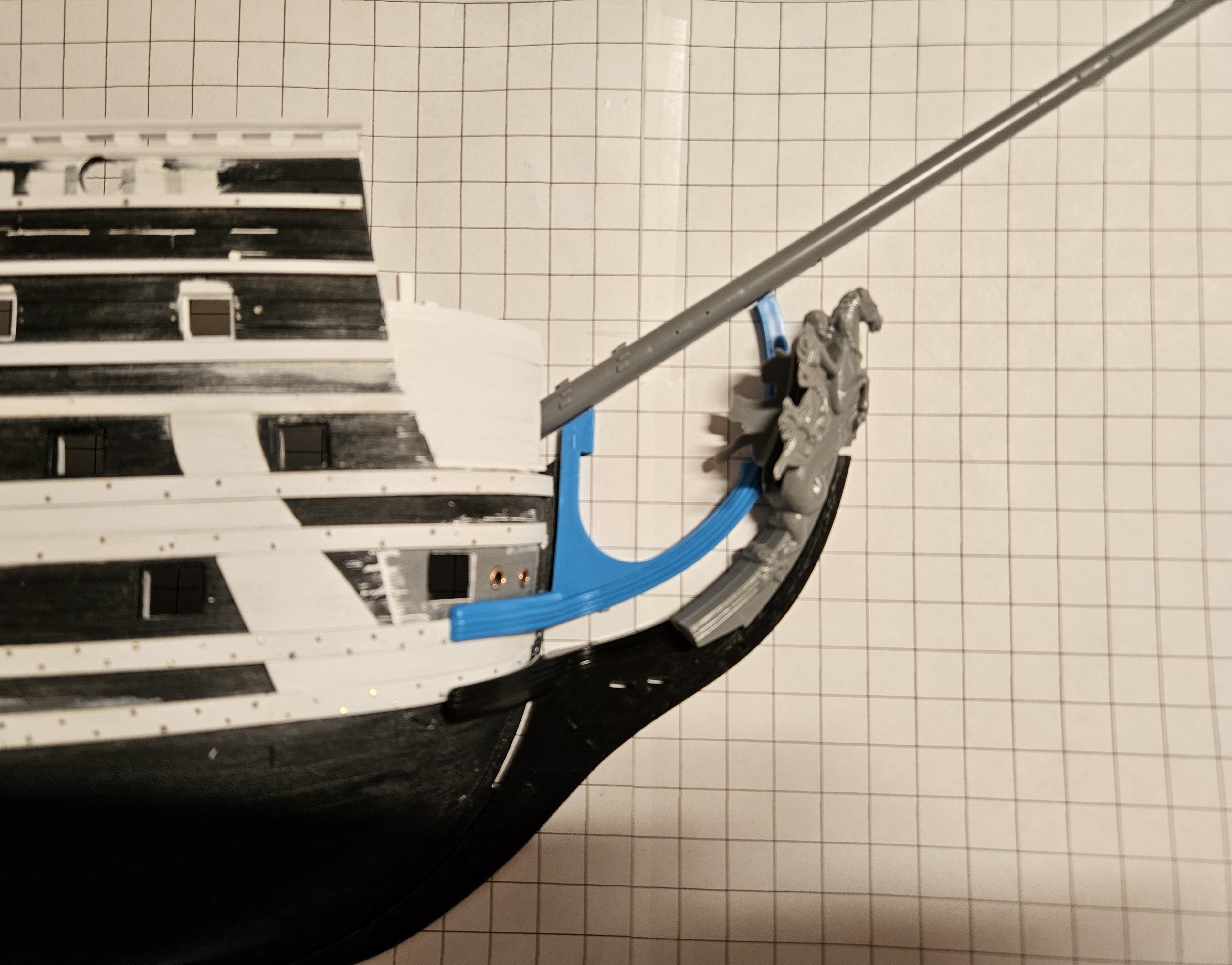
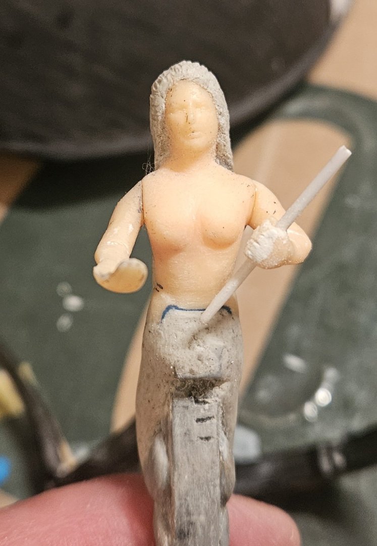
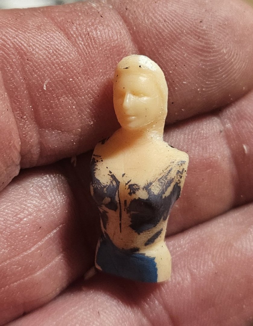
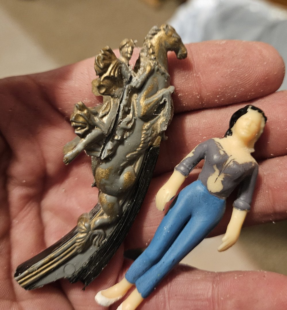
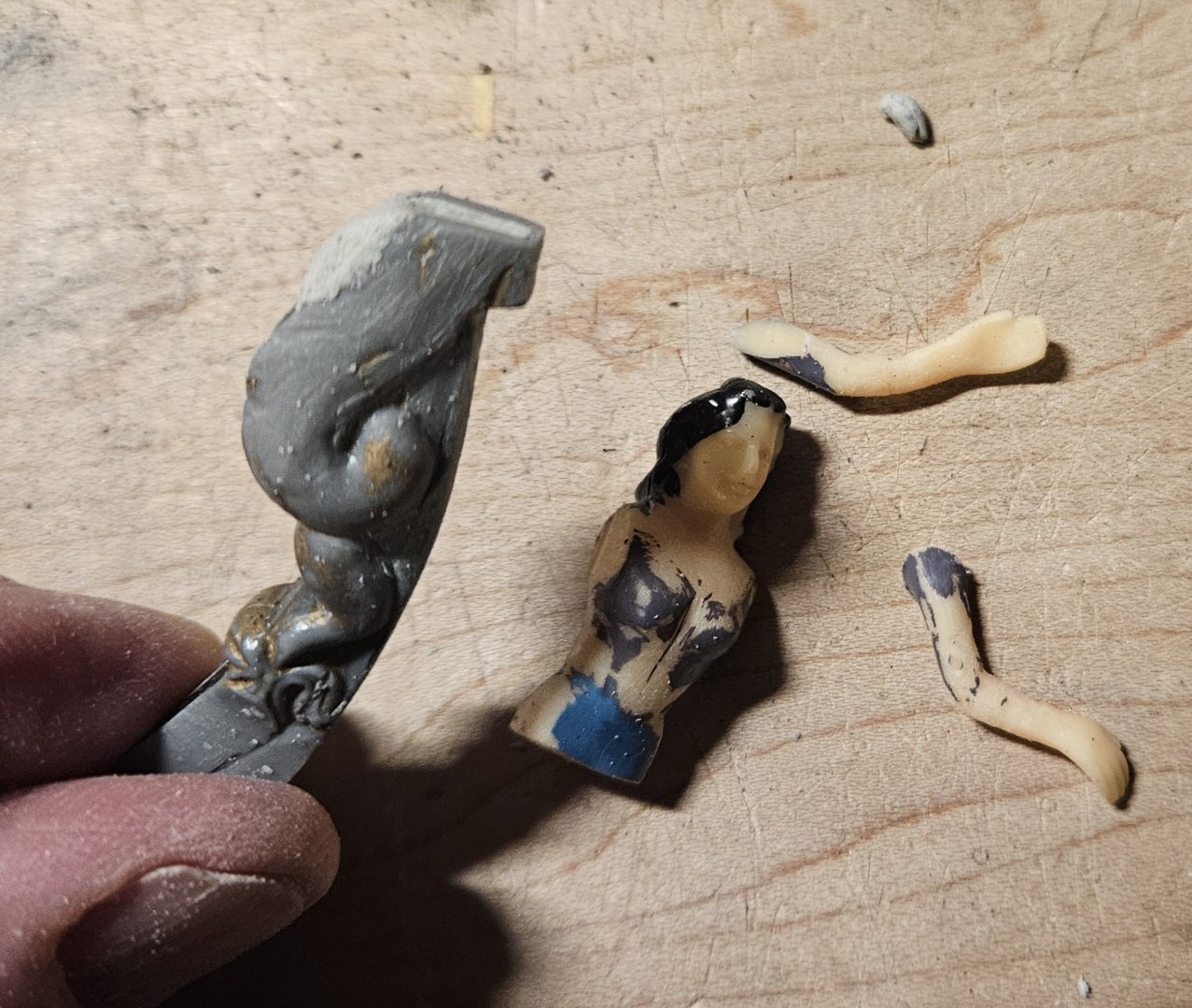
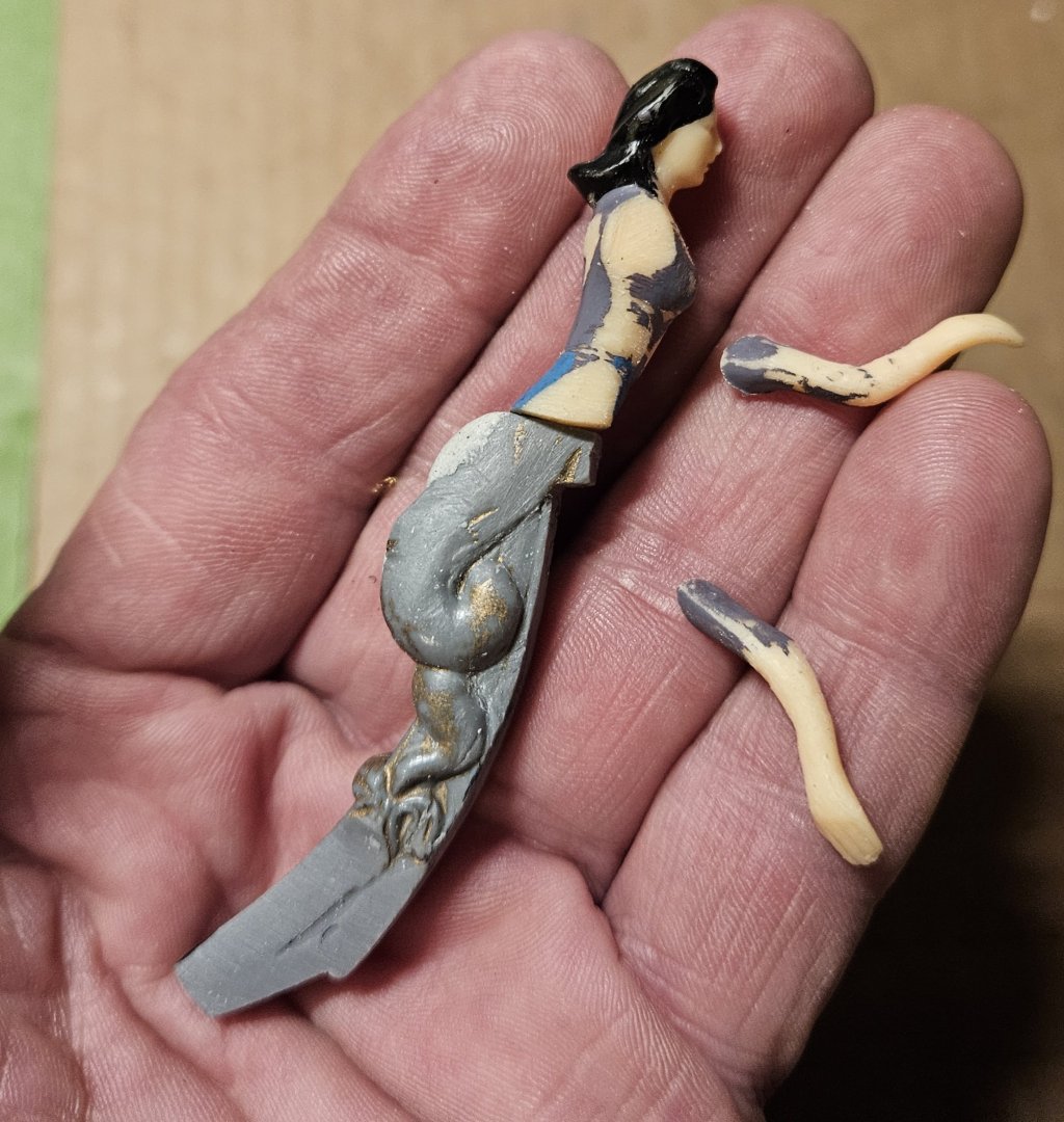
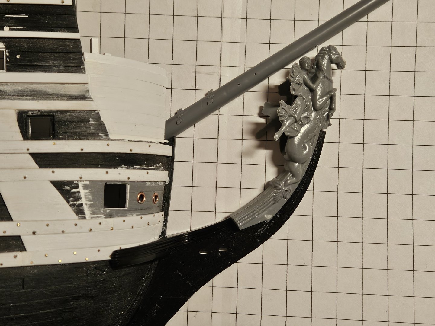
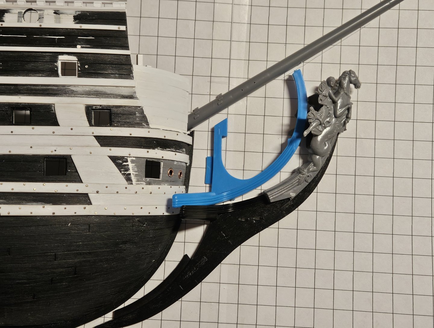
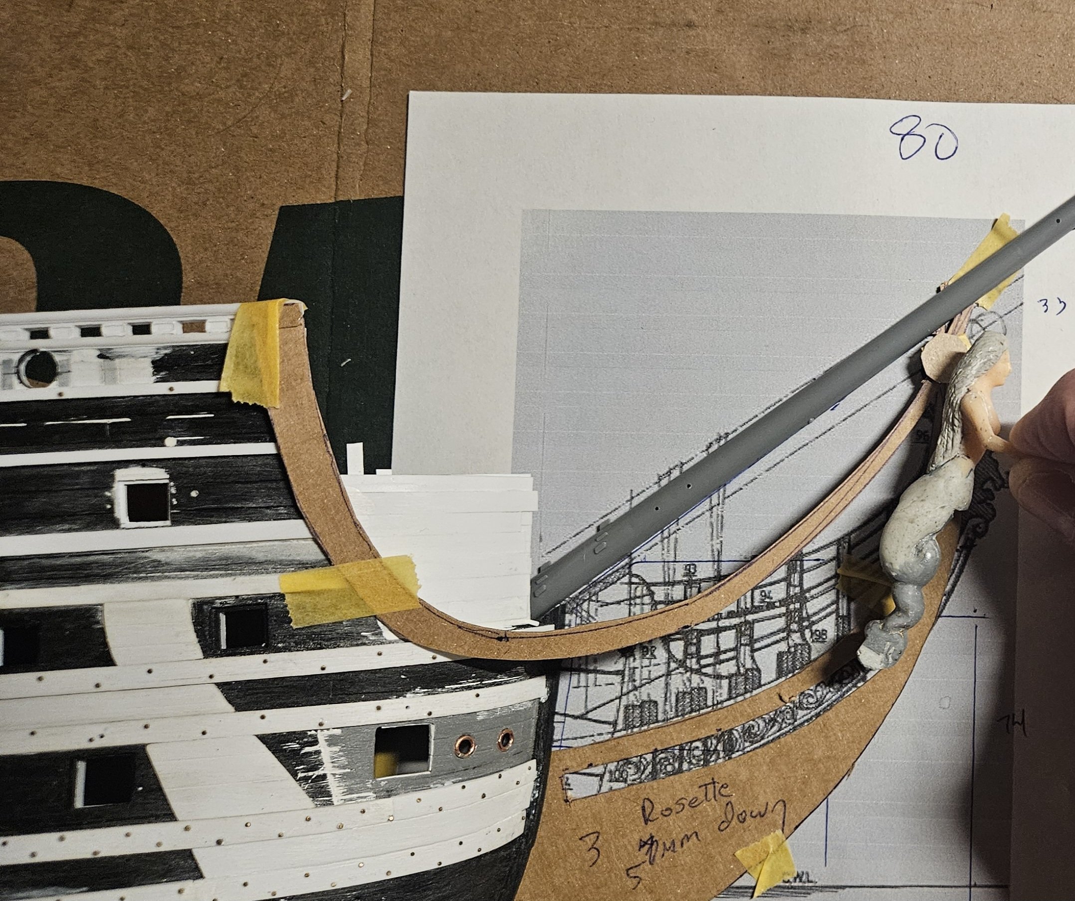
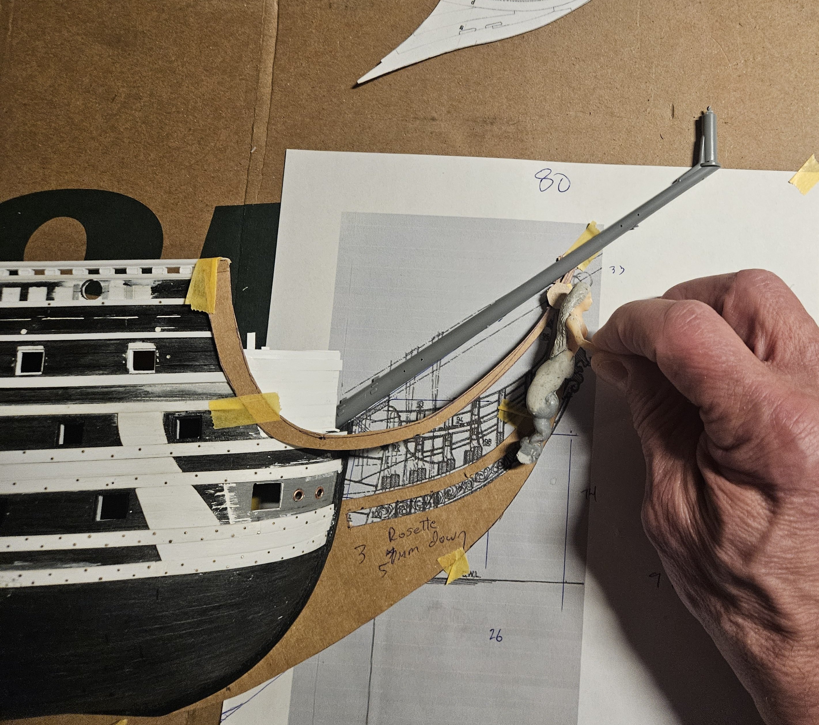
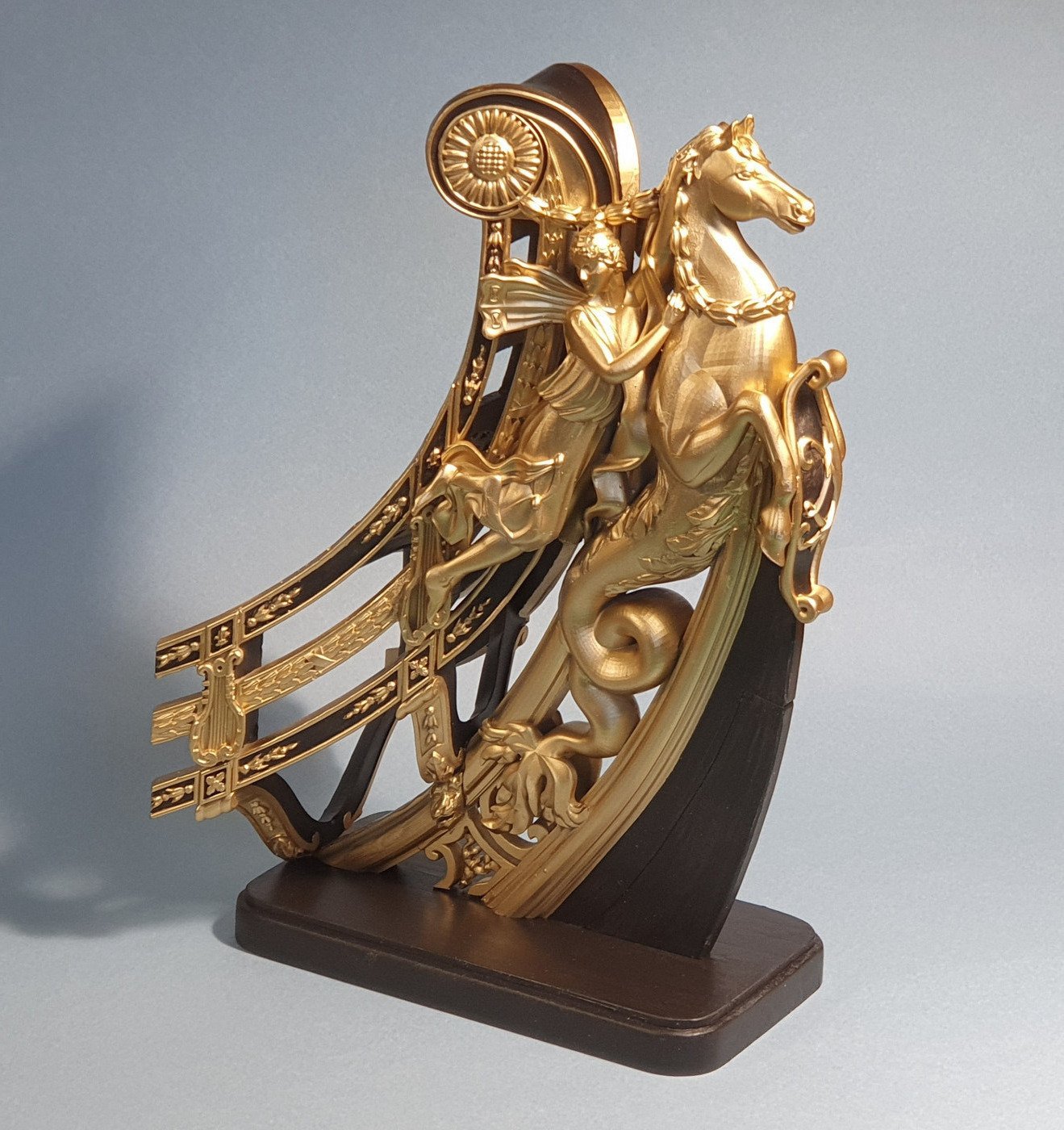
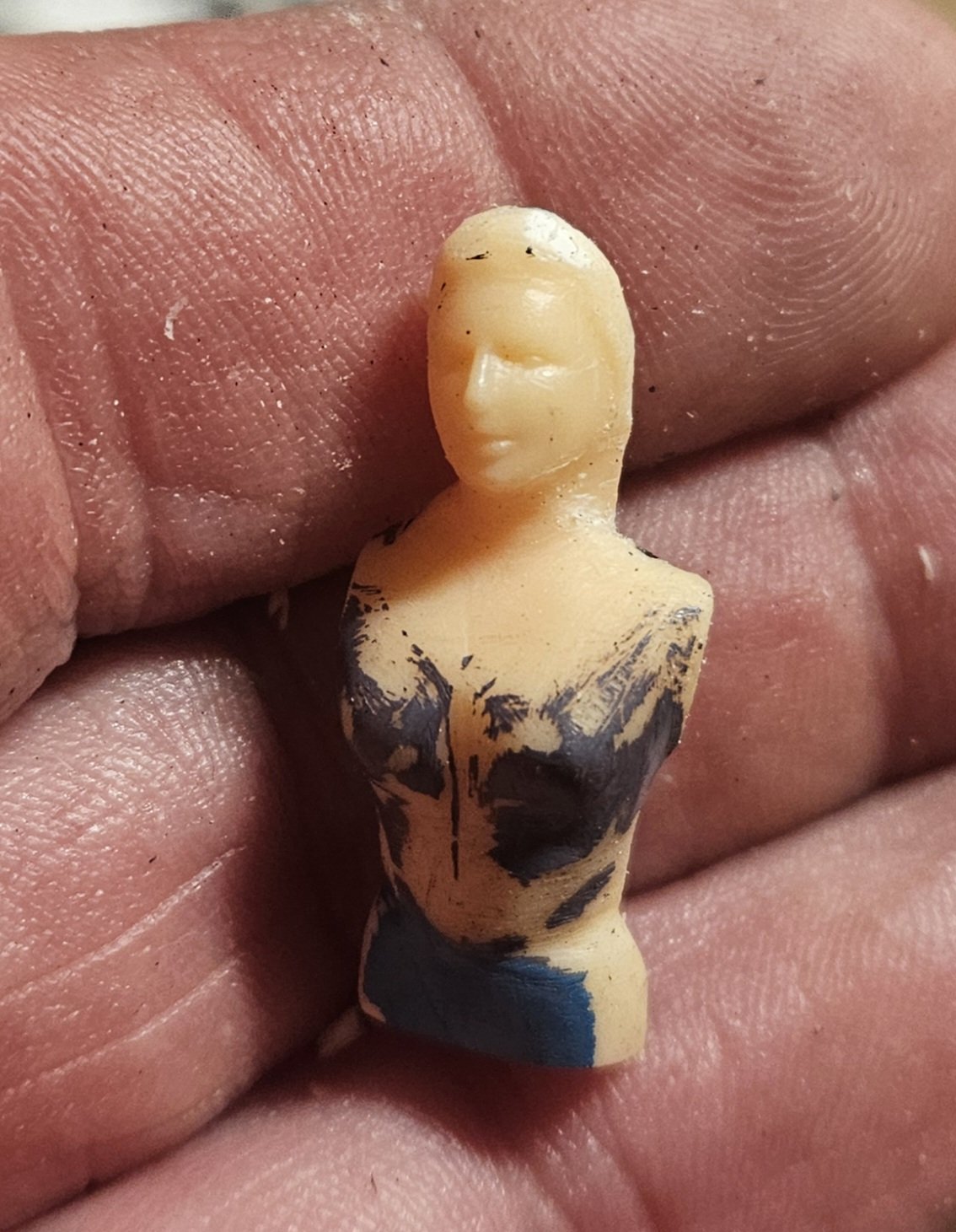
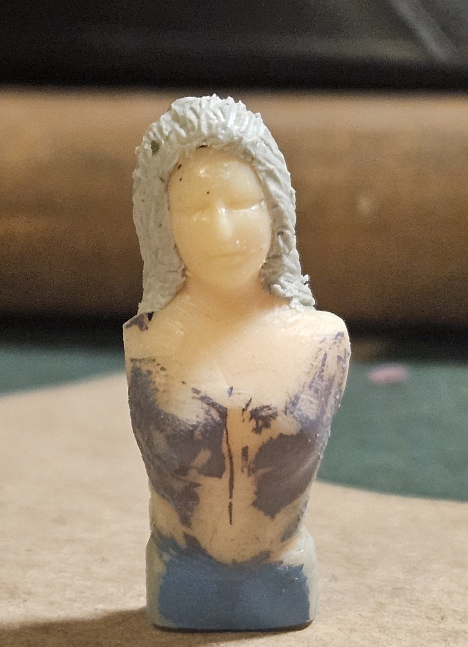
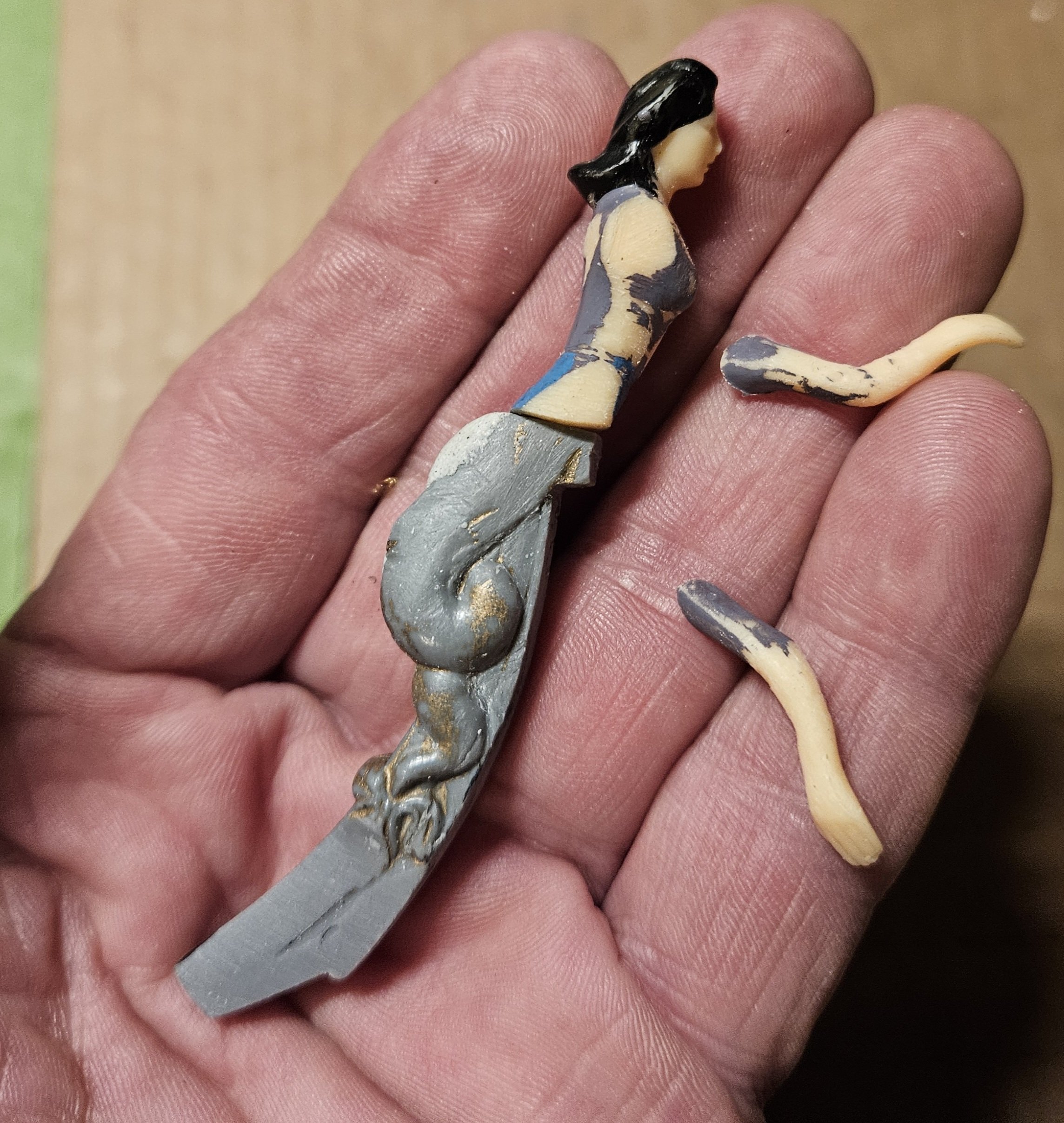
Before I can proceed with further work on a more "Dutchy" appearing bow, I need to get my new figurehead done so I can make precise measurements. This is what GuyM said about the figurehead of the first Soleil Royal circa 1668 in his treatise EL SOLEIL ROYAL and the royal ships of Louis XIV... "the figurehead, which consisted of a mermaid with an outstretched arm holding a globe, or sun, crowned, and a sceptre in the other hand folded against her body". I was focused on trying to find something 1:100 scale that I could use as a mermaid... and I finally realized that the figurehead is much bigger than a person. A quick calculation showed that I needed 1:30 scale. Lo and behold, I quickly found a packet of 15 people in 1:30 scale. Here is the future mermaid alongside my figurehead from my unfinished 1977 SR. I got out the saw and did some surgery on both. I will be a lot easier than I thought to reposition the arms to hold a scepter and a globe... but I did pack the inside of the figurehead with ApoxieSculpt to fill the large hollow. Alas, I will let the ApoxieSculpt dry until tomorrow before I glue her on and reattach her arms. I also sanded/scraped away all of the kits details on the figurehead so that I could add my own. This photo gives you an idea of what she will look like - about the same height as the kit figurehead down to a millimeter. Tomorrow I will also be able to pretty her up, starting with Tamiya putty. Guy notes that she was "scantily dressed", with sea shells on her chest and draped with necklaces. Obviously, it will be easier if I go sans shells, and almost all of the ship figurehead drawings and photos that I can find have a bare-chested mermaid. I have time to decide which way to go.
- 432 replies
-
- 4
-
-
-
- soleil royal
- Heller
- (and 1 more)
-
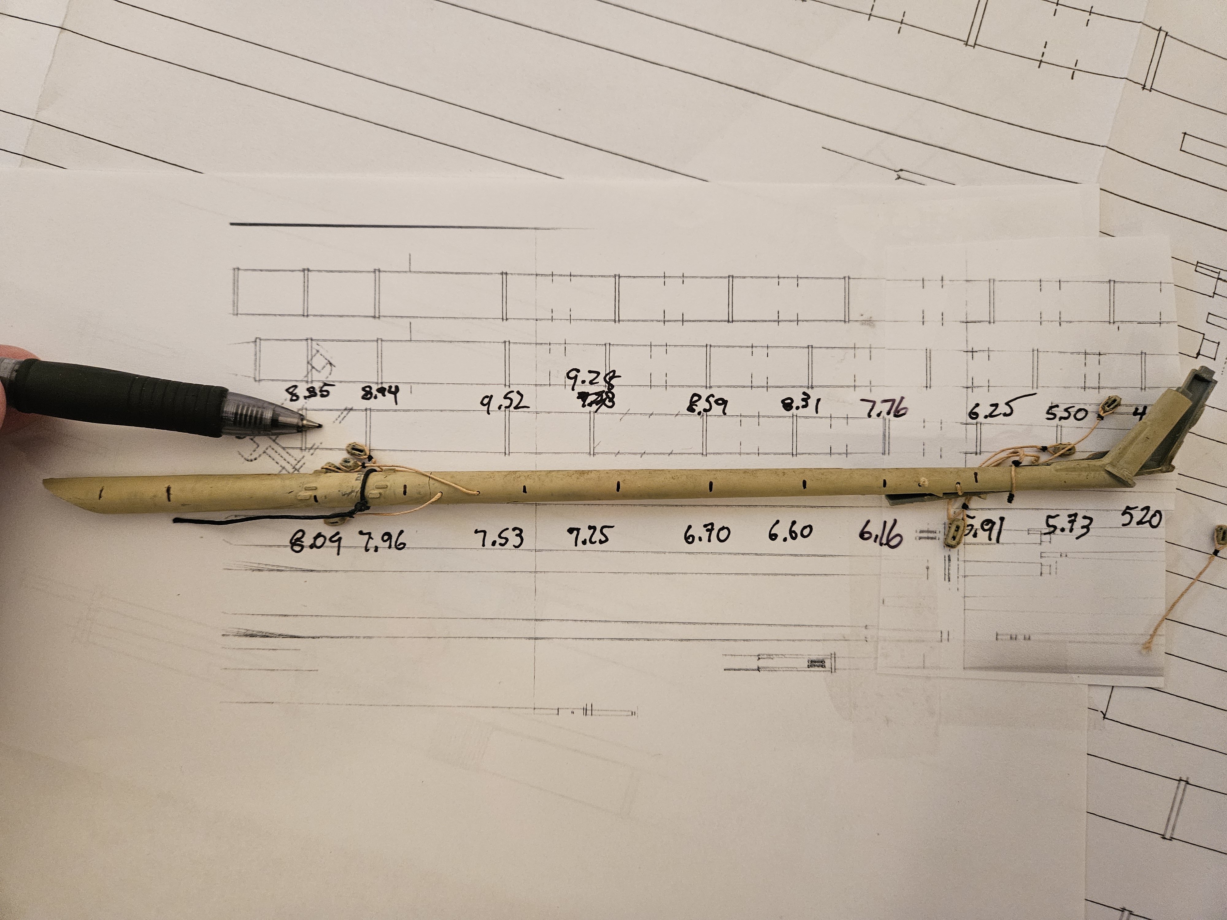
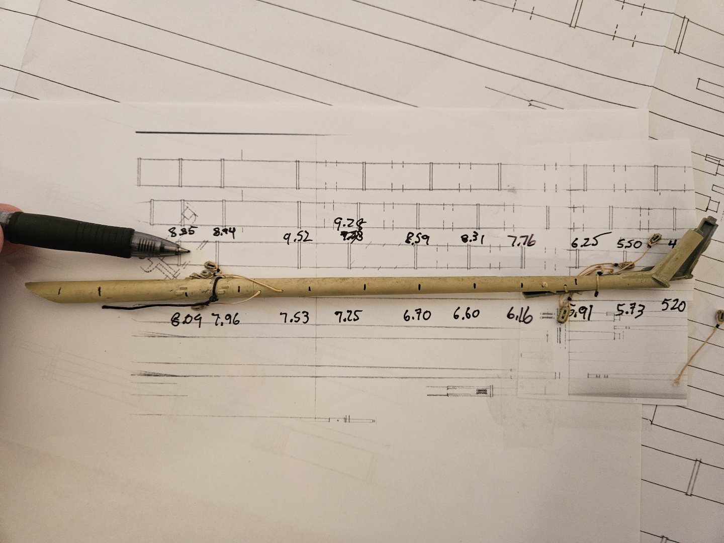
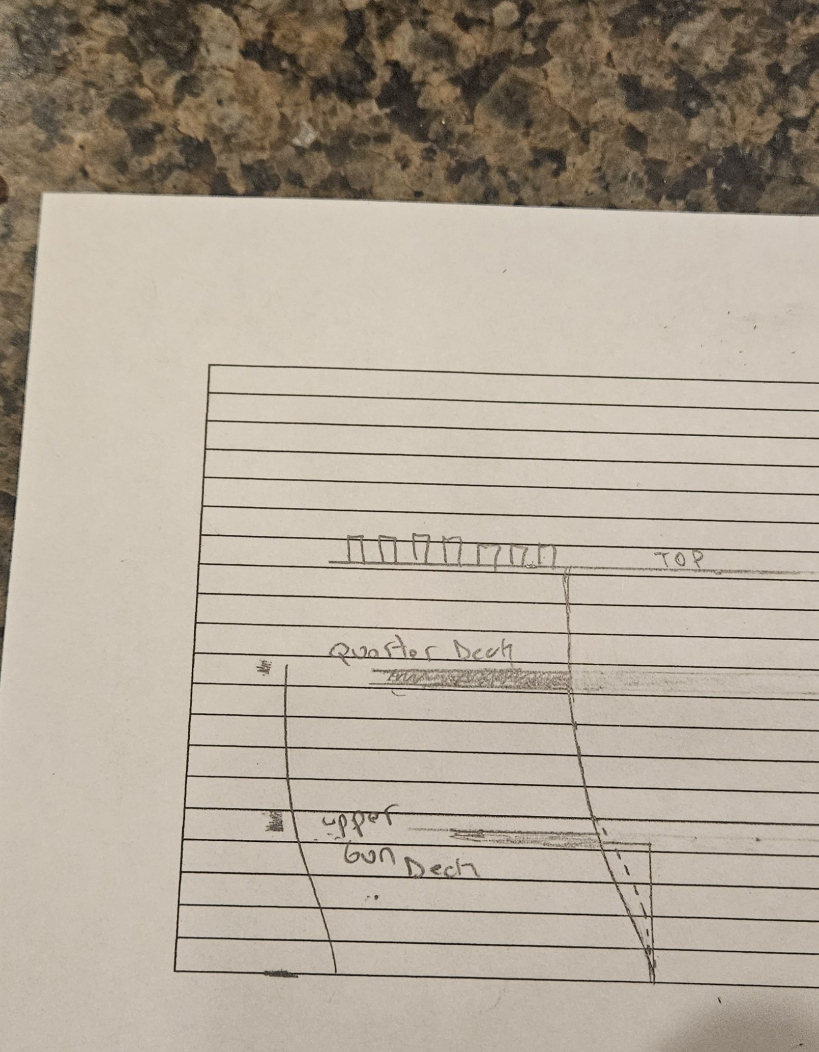
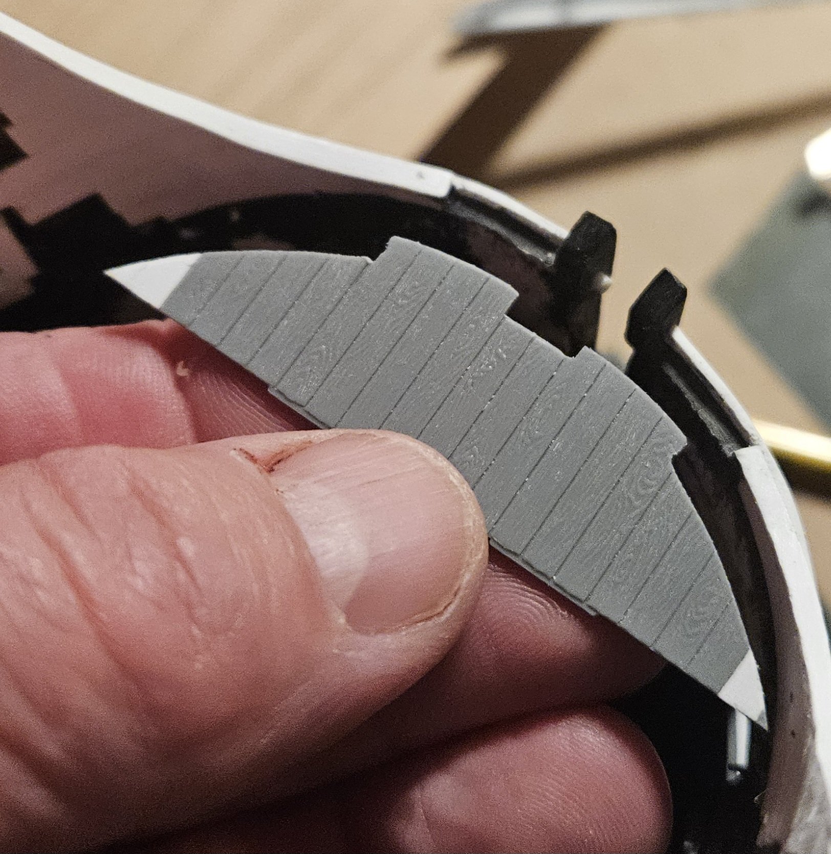
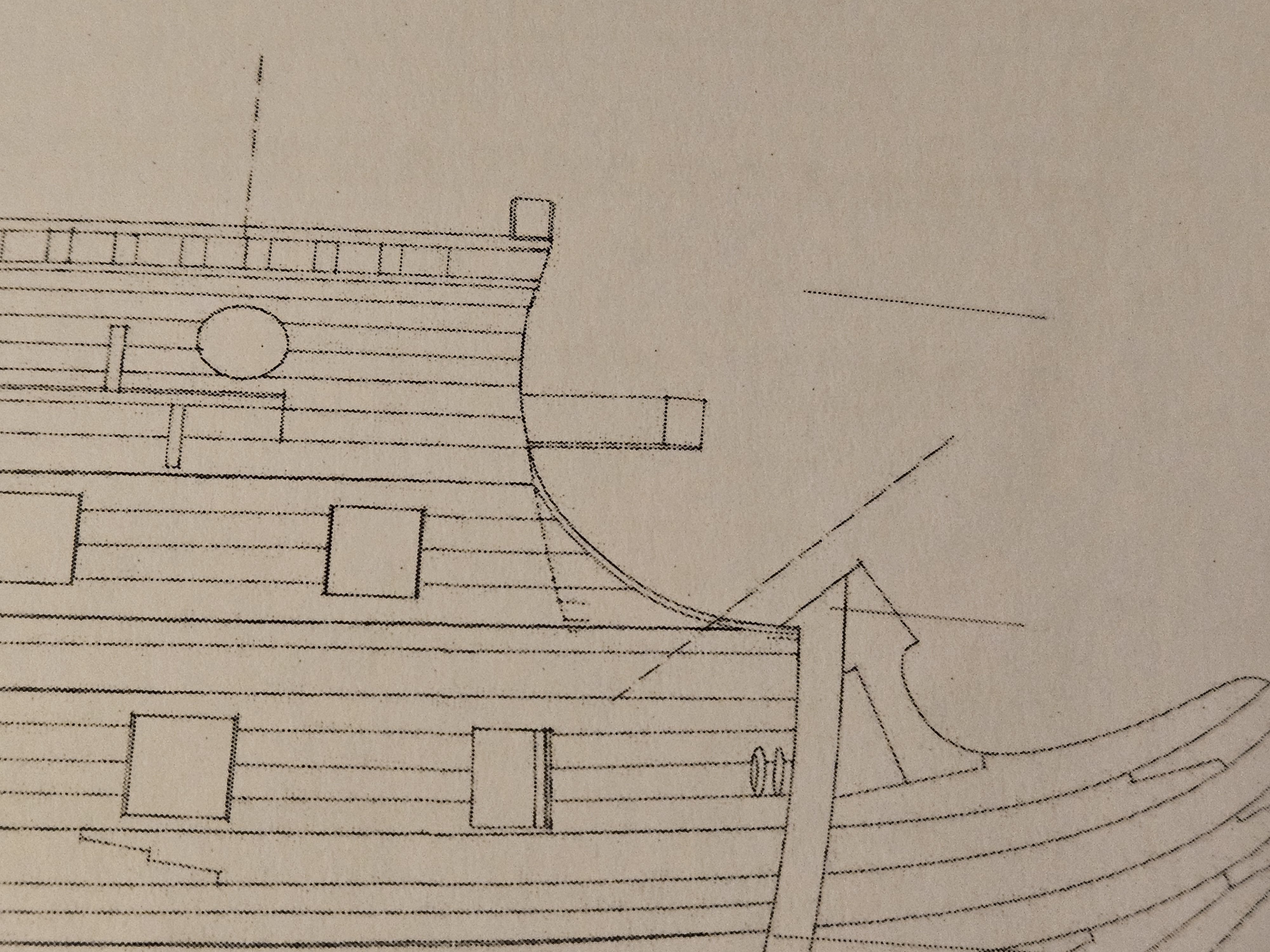
A lot to unpack here, so hopefully pictures are worth a thousand words. These three drawings have the look that I am trying to emulate for SR 1671... that longer, lower beak that looks "Dutchy", per Marc LaGuardia. In order to achieve this, I laid down some graph paper and played around with the kit parts. By playing around with the bowsprit posItion, that seemed to be the easiest path forward to get the "Dutchy" look. The red and yellow and green marker colors are different bowsprit positions/angles. Next, I duplicated the existing Heller kit appearance with its 32 degree bowsprit angle. Again, the existing kit parts were used as it was easier to see against the graph paper. Again, this is the standard appearance. Next, I sawed off 6mm of the black bowsprit support located at the very tip of the bow. This obviously lowers the bowsprit by 6mm and makes the bowsprit almost touch the figurehead. If I had left the blue cheek piece in, it would clearly clash with the bowsprit. Finally, the picture below shows how lowering the bowsprit allows me to "lengthen" or "push forward" the entire head. The bowsprit angle here is 35 degrees, compared to 32 degrees for the kit. I am not sure yet as to what my exact bowsprit angle will be, but in the next day or so I will be able to determine the curve of the head rail (which will also allow me to trim the bulwark extensions that wrap onto the bowsprit deck. I am not sure that I will have quite enough room to have the entire bowsprit plunge through the bowsprit deck, as opposed to primarily going through the beakhead bulkhead as in the kit. The black oval on the bowsprit deck indicates a potential hole for the bowsprit to go through. It may have to cheat every so slightly through the beakhead bulkhead, Finally, I have a friend who has a lathe and is a very good woodworker. I saw on Dfolgado's SR build log (Ships of Scale) that he thought the Heller kit masts were often incorrect. I did check the bowsprit against the St Phillipe monograph dimensions and it does suggest the kit bowsprit is too long and thin(?). It will be interesting to see how the lathe turned bowsprit turns out.
.thumb.jpg.b2f4d375a2ea92de092da6798d6c53e1.jpg)


- 432 replies
-
- 4
-
-
- soleil royal
- Heller
- (and 1 more)
-
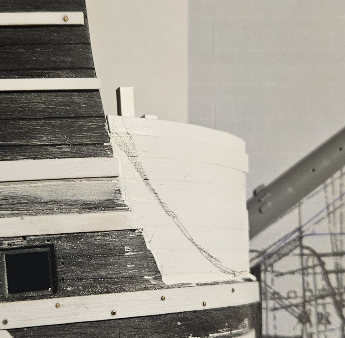
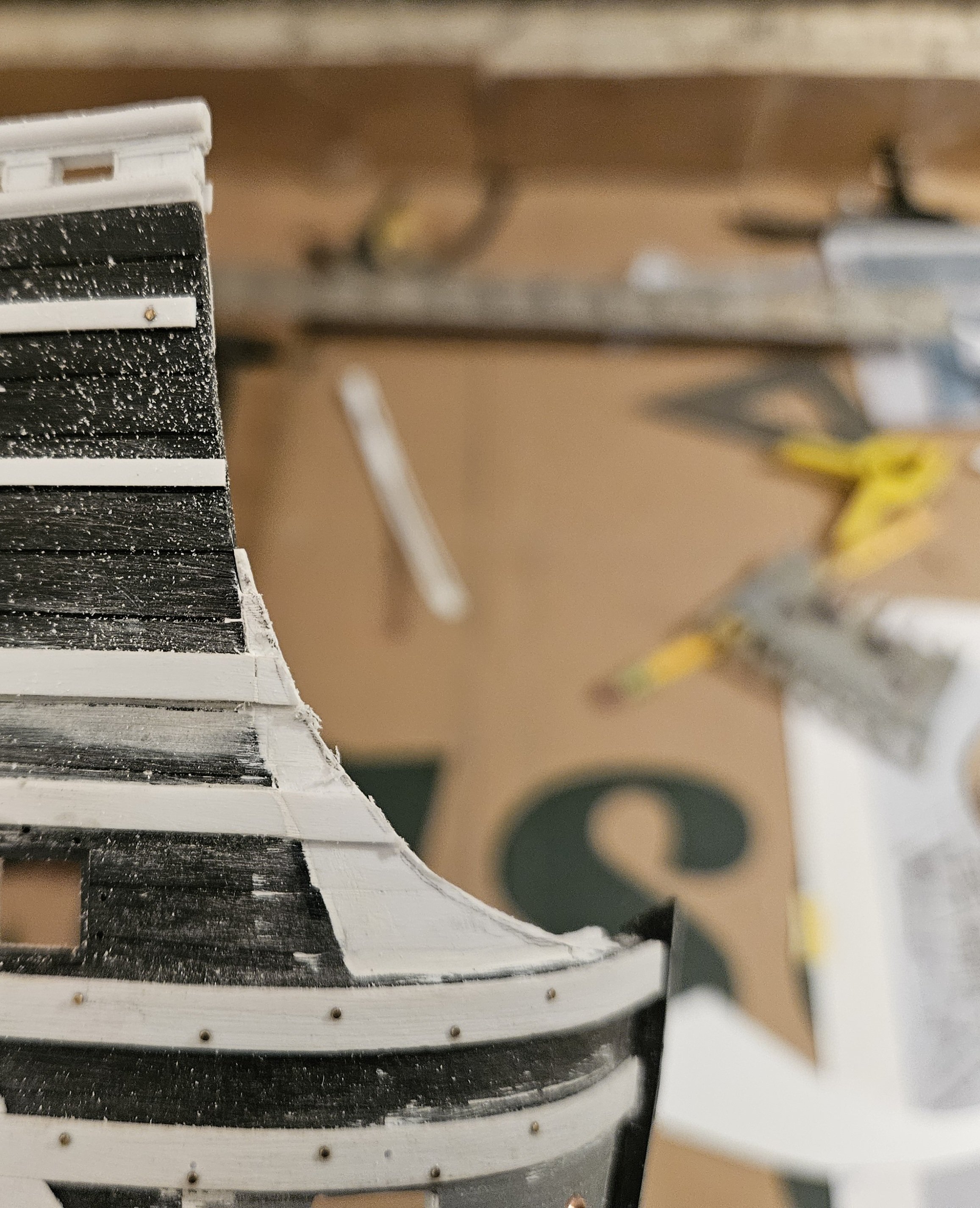
Well, the extension of the front bulwark that partially wraps the bowsprit deck has gone very well. Like many aspects of this build so far, what appears to be daunting turned out to be fairly straightforward... and Marc's suggestion certainly made this a lot easier! First, I used the St Phillippe monograph to see where the extension tapers down to the bowsprit deck. Then I added the (temporary) vertical forming pieces as Marc suggested The front bulwark is 2.3mm wide at the base and tapers to 1.60mm as it rises. So I first "planked" with some 0.4mm sheet, and then added additional planks of varying width and thickness. I finished the outside with 4mm wide planks which almost exactly match the plank widths on the Heller kit. Once the starboard side is done, I will attach the hull halves together (temporarily) so I can work on my beakhead... and that will allow me to see what the sweep of my head rails will be, as the tapering downward curve of the bulwark extension will match the sweeping curve of the head rail. The only "scary" part will be wasting away the vertical formers and gently shaping the bulwark extension.


- 432 replies
-
- 4
-
-
- soleil royal
- Heller
- (and 1 more)
-
Marc, I like your idea and want to make sure I understand this! Here is a very crude paper template I made, basically following what I see on the ST. Phillippe monograph... I am assuming the top wales would continue to wrap on this cheeking piece? Neither of the drift rails would continue as they are too high,. I used a few dots of super glue to attach some 2mm thick rods as drawn in your sketch by attaching them to the inside of the hull, and I am holding a piece of plank to show how they would wrap the outside of the formers. However, I can't wrap my head around how I plank on the inside of the formers? Also, wouldn't the formers, as they are glued onto the inside of the hull, interfere with the fitting of the bowsprit deck? P.S I think I will stay the course for SR 1671. It's possible I could eventually fit the masts but NOT rig it yet, but start again on a hull for either Royal Louis 1668 or Dauphin Royal 1668. I think I could proceed a lot faster on a second hull, using what I learned from this hull. Also, I am thinking 3D printing technology continues to jump ahead by leaps and bounds, and just maybe, the complicated sculptures on Royal Louis will be a lot more feasible to make in 1-2-3 years??

- 432 replies
-
- 2
-
-
- soleil royal
- Heller
- (and 1 more)
-
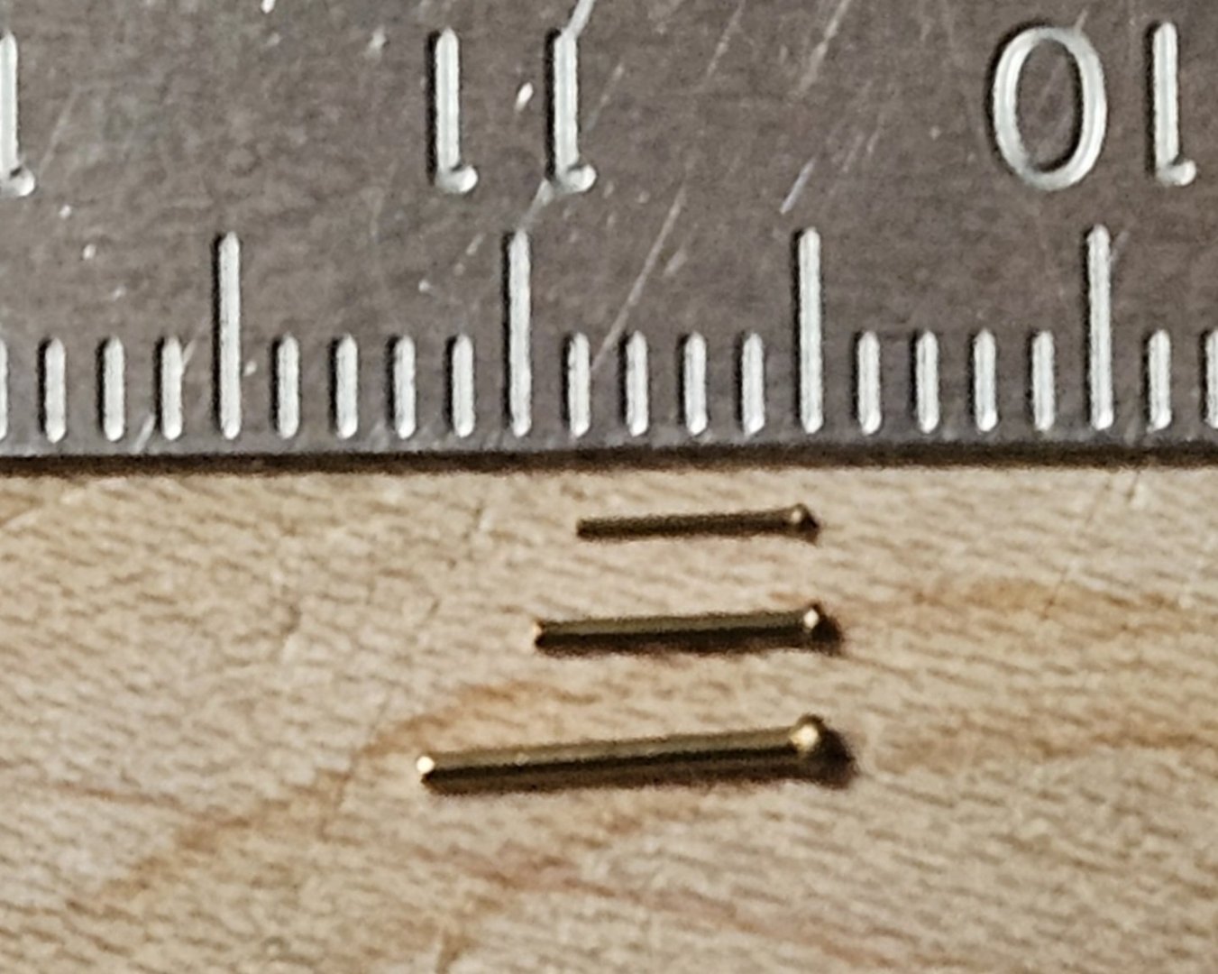
And just a side note as I finish the nails in the wales... well, a drift rail. I sourced some tiny brass nails.... from top to bottom, the round head diameter is 0.020", 0.027", and 0.47". It wasn't too bad to use the middle nails for the wales... but I decided to try the tiny nails on top for the top drift rail, always thinking of scale (the bottom drift rail will have listons d'ors, so need to apply nails). Thank God I only have about 40 nails/bolts to apply as these little buggers are hard to handle - I am happy if I only lose 30% to the universe! Will it make a difference? Thanks to Marc (Hubac's Historian), I try and make my first thought "is it to scale?". And the best I can say is.. "I know that they are there!"
- 432 replies
-
- 3
-
-

-
- soleil royal
- Heller
- (and 1 more)
-
Marc, I am planning on having those exterior bulkheads sweep forward... I wish I knew the proper name, but I am very interested in your idea!
- 432 replies
-
- 1
-
-
- soleil royal
- Heller
- (and 1 more)
-
Ahh, the toothbrush will definitely help.. thank you!
-
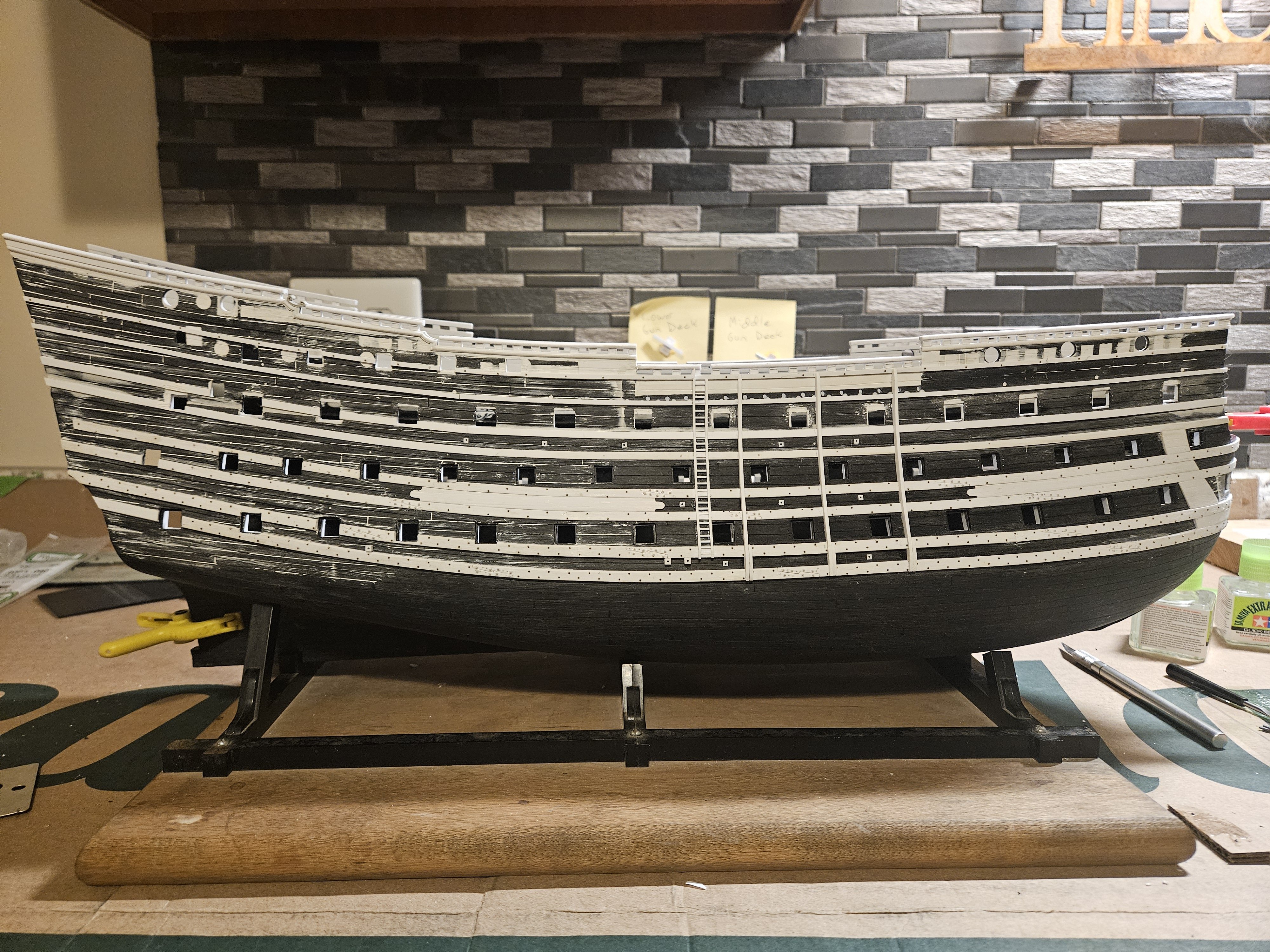
So in the last two weeks, I have been able to put a lot of work into the ship... but yet, if you look at the following pictures, it would seem that nothing has changed. By way of explanation, I have found myself doing what Penelope (wife of Odysseus) did.... whereas she wove a burial shroud by day, she unraveled most of it every night. So in the last two weeks, I unraveled a lot of things on my ship! By way of explanation, I did a lot of detail items, like rabbeting the gun ports, making through bolts for the wale scarf joints, etc. BEFORE I filled in the hull plank lines with Tamiya putty so I could rescribe plank lines to match the sweep of the wales. Also, I didn't know I would be attaching the bulwarks at such an early stage; Apoxie Sculpt did a wonderful job of filling any gaps between the hull and the bulwarks, but talk about dust! And then I grew unhappy with the gun ports on the top deck - I felt that I hade made them too small (7mm x 6mm). So I cut out all of my prior rabbeting, and enlarged and then checked every gun port for level on the top gun deck, as well as the quarterdeck and poop deck. OK... I liked that a lot better and just finished rabbeting the gun ports. So.... I am back where I was two weeks ago! And that means glue in the cleats on the inside of the bulwarks, and I might be priming the hull this weekend. I do have a general question on ship clean up... I find myself creating lots of dust and small particles, from scribing plank lines, from drilling out the Tamiya putty that settled in gun port lid holes, sanding Apoxie Sculpt, etc. My only solution has been to bathe the hull pieces in a bath tub with a bit of dish soap. This does seem to get rid of the dust, and it doesn't seem to cause damage to the ship or cause tiny parts to break off. But is there a better way to clean this debris off?

- 432 replies
-
- 3
-
-
- soleil royal
- Heller
- (and 1 more)
-
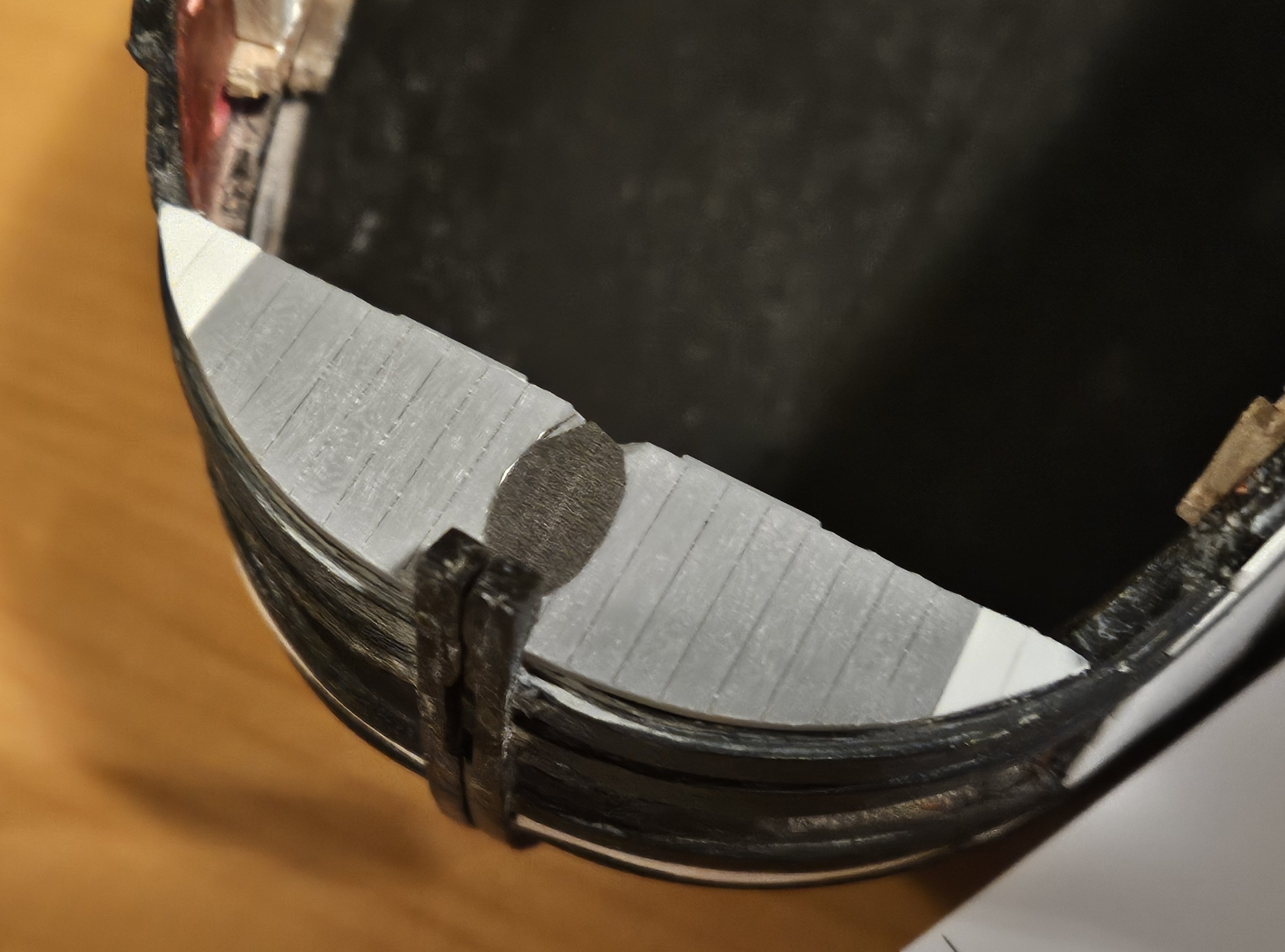
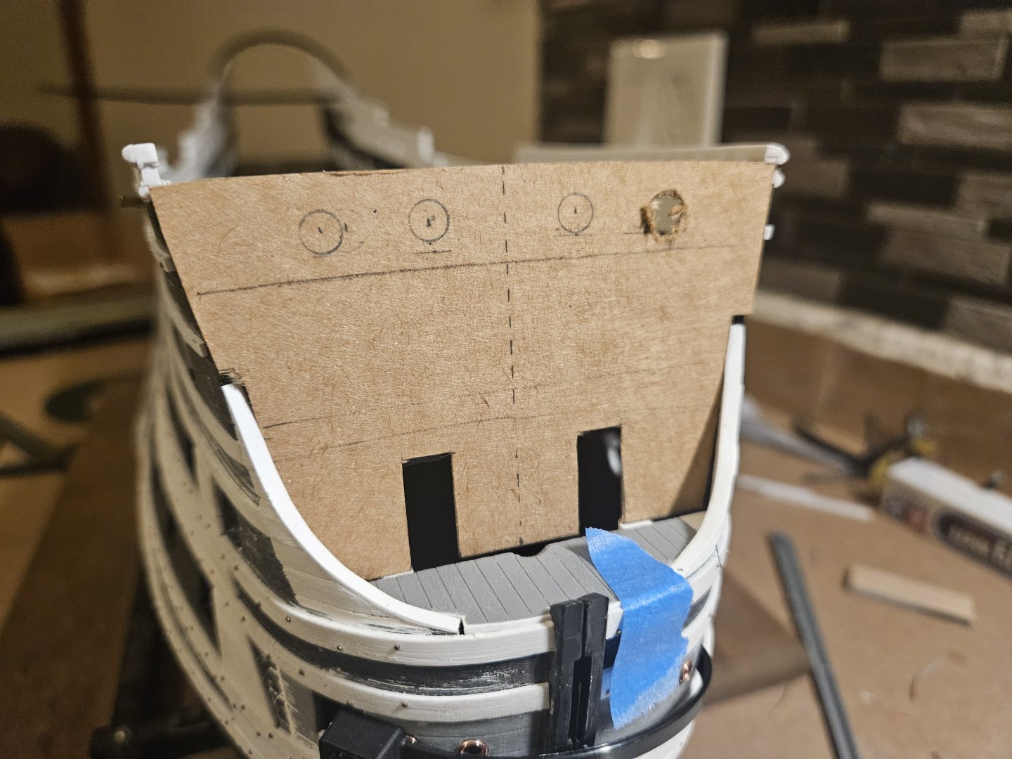
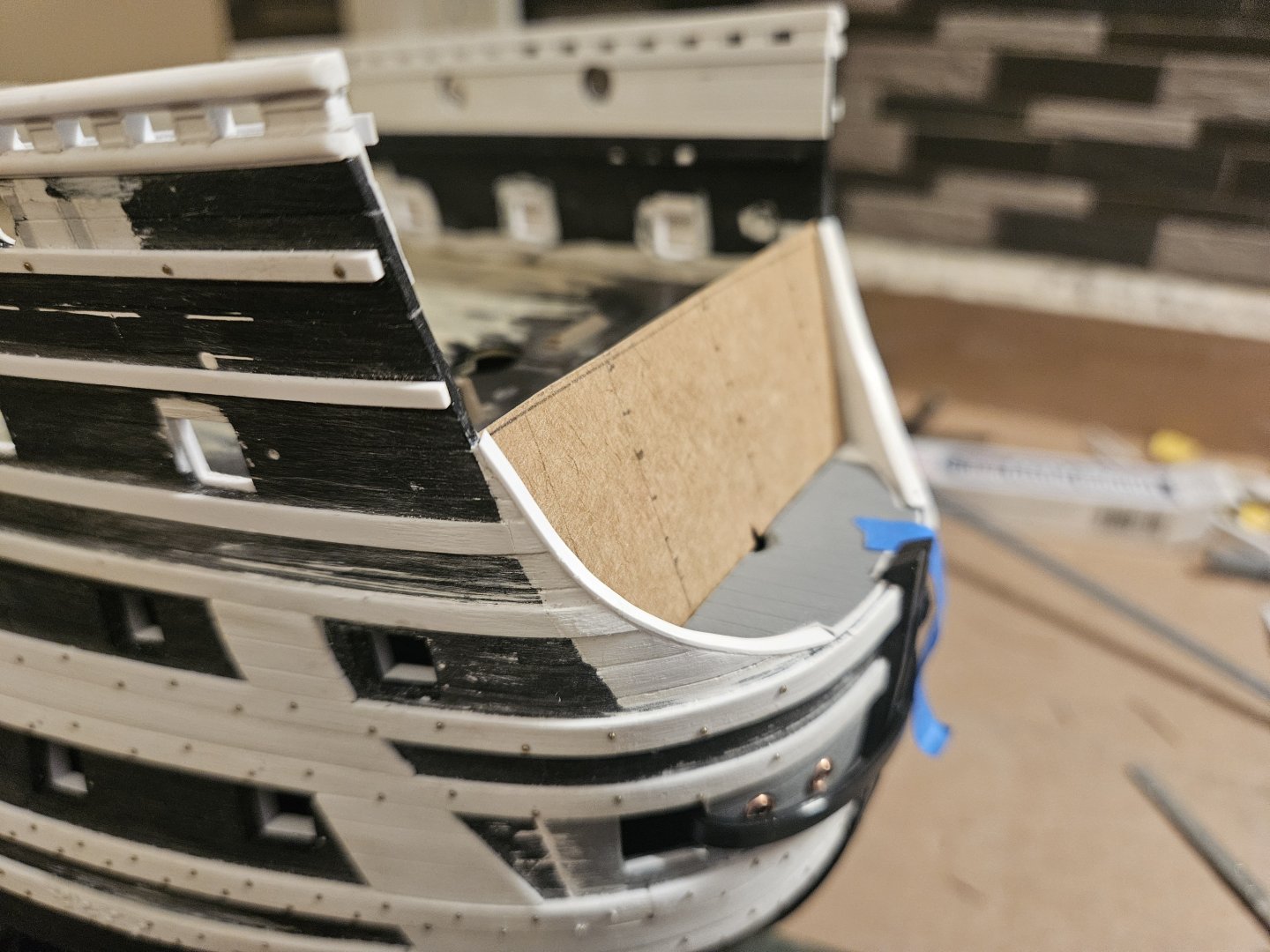
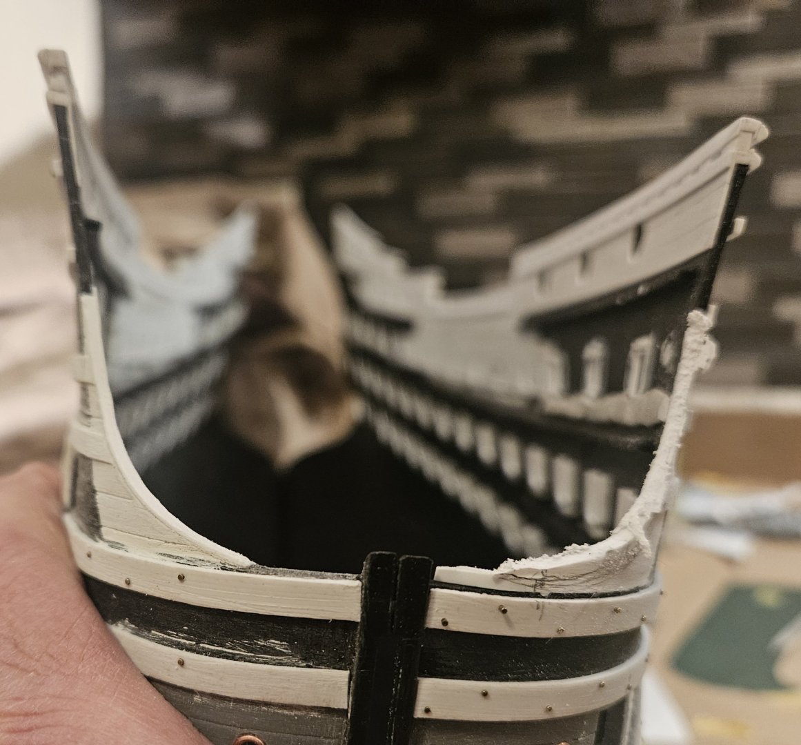
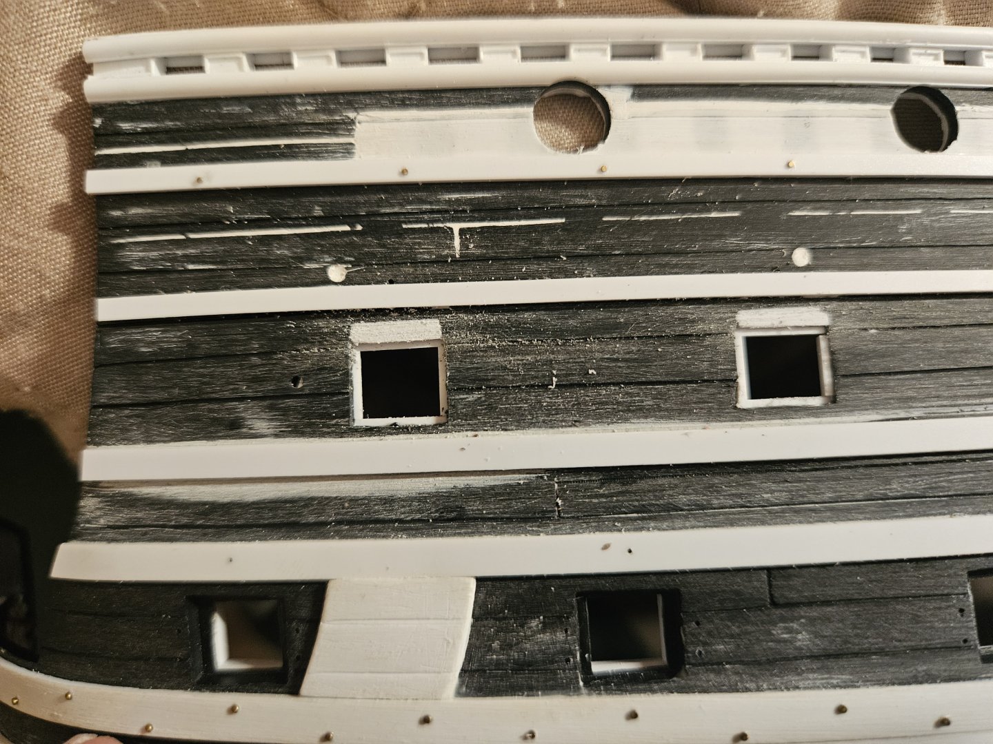
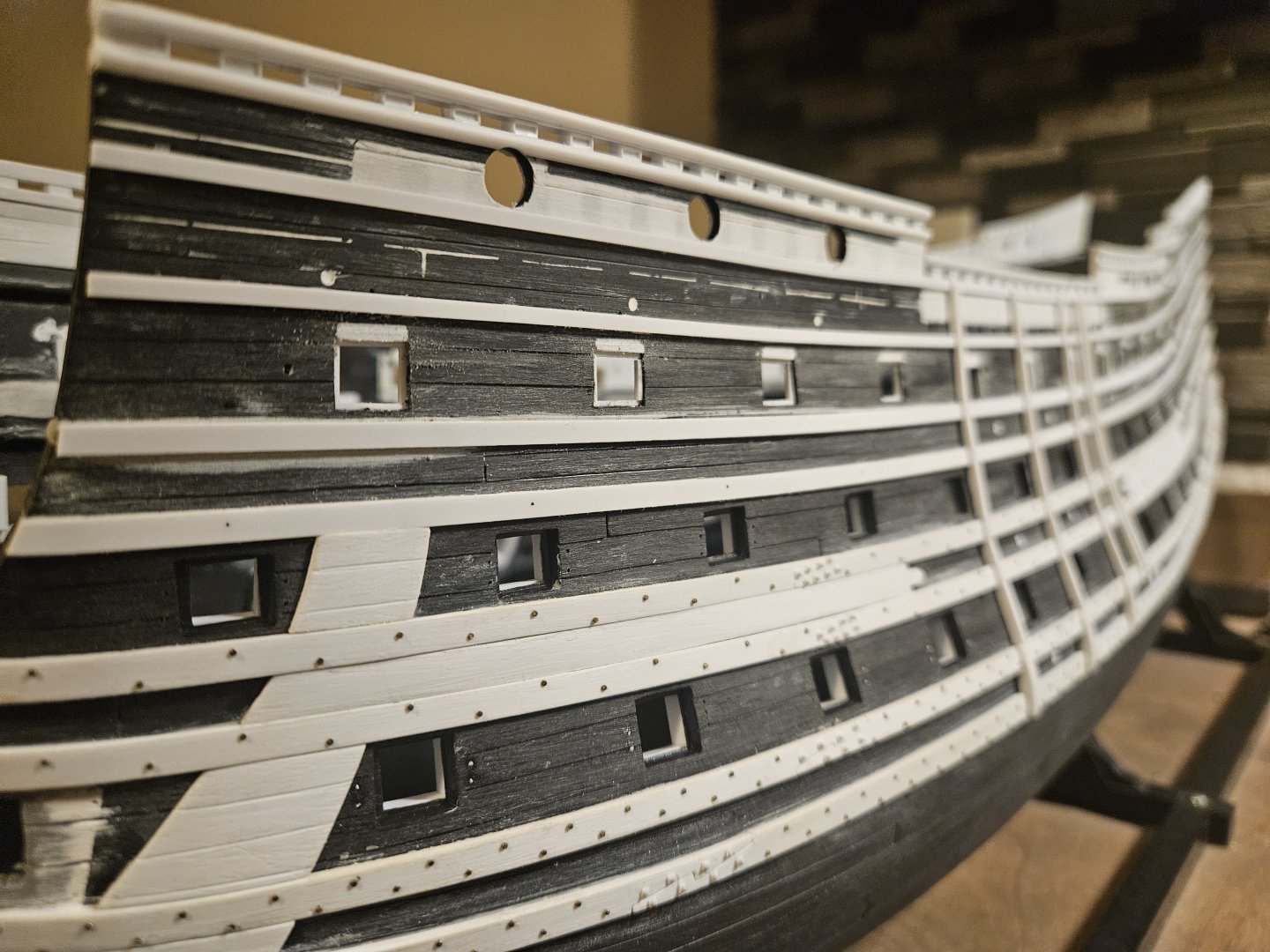
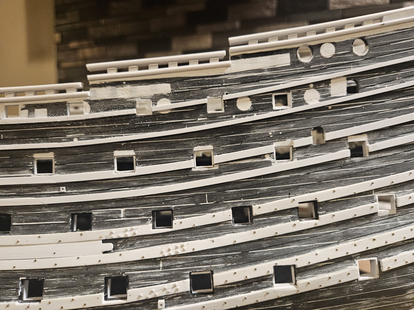
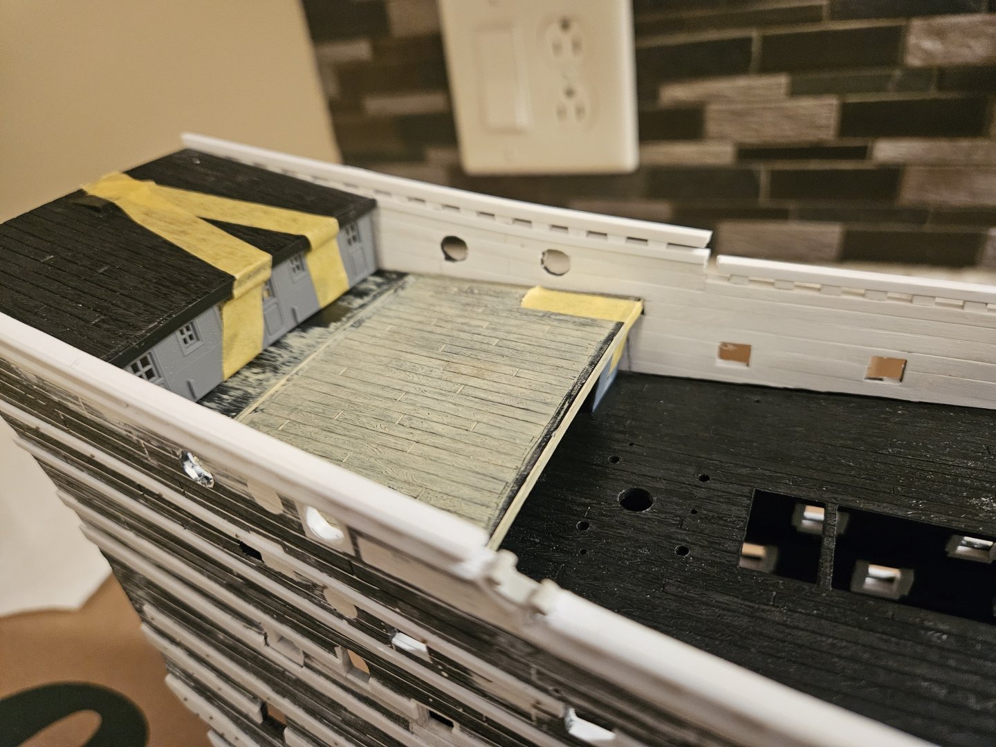
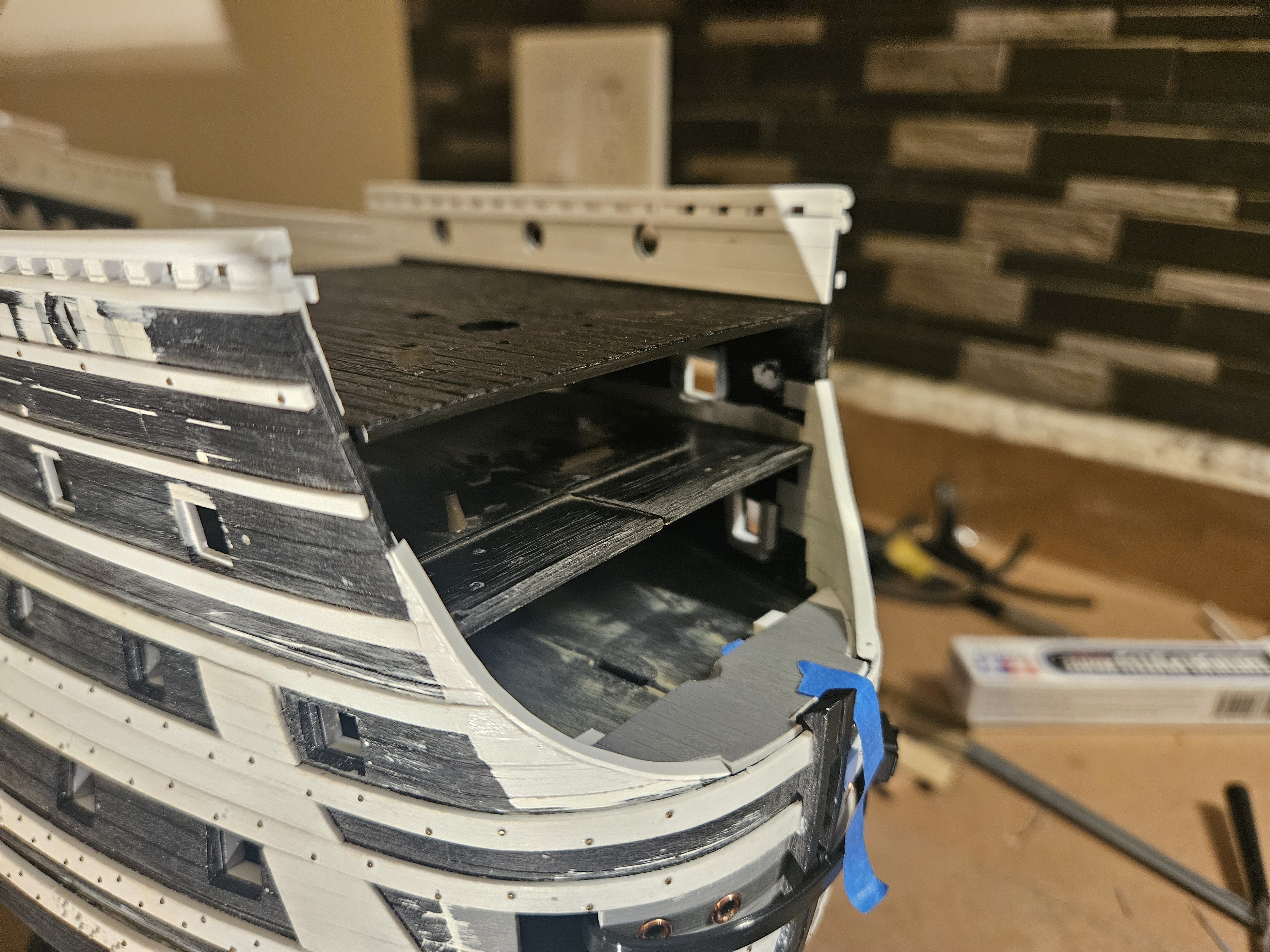
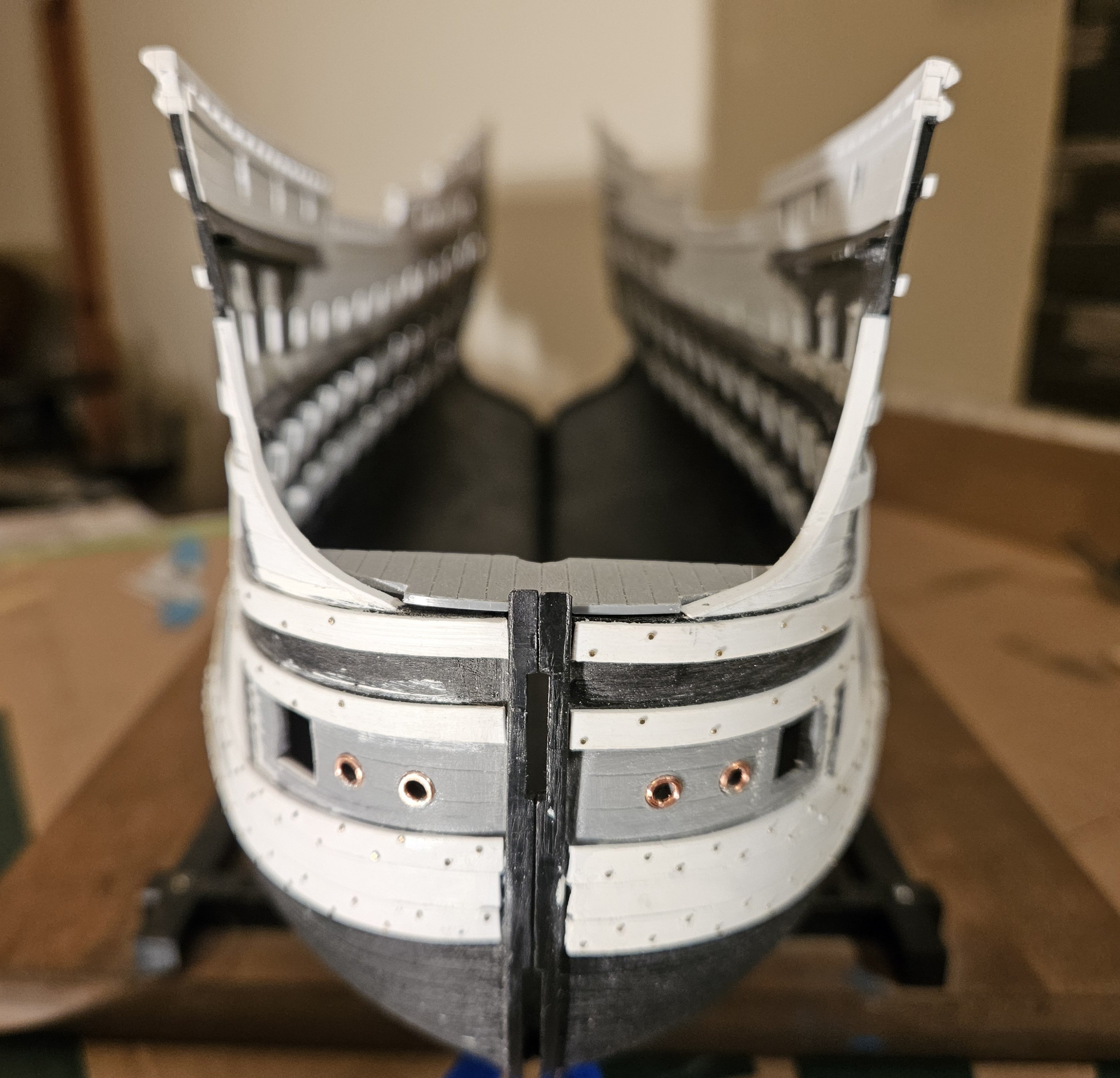
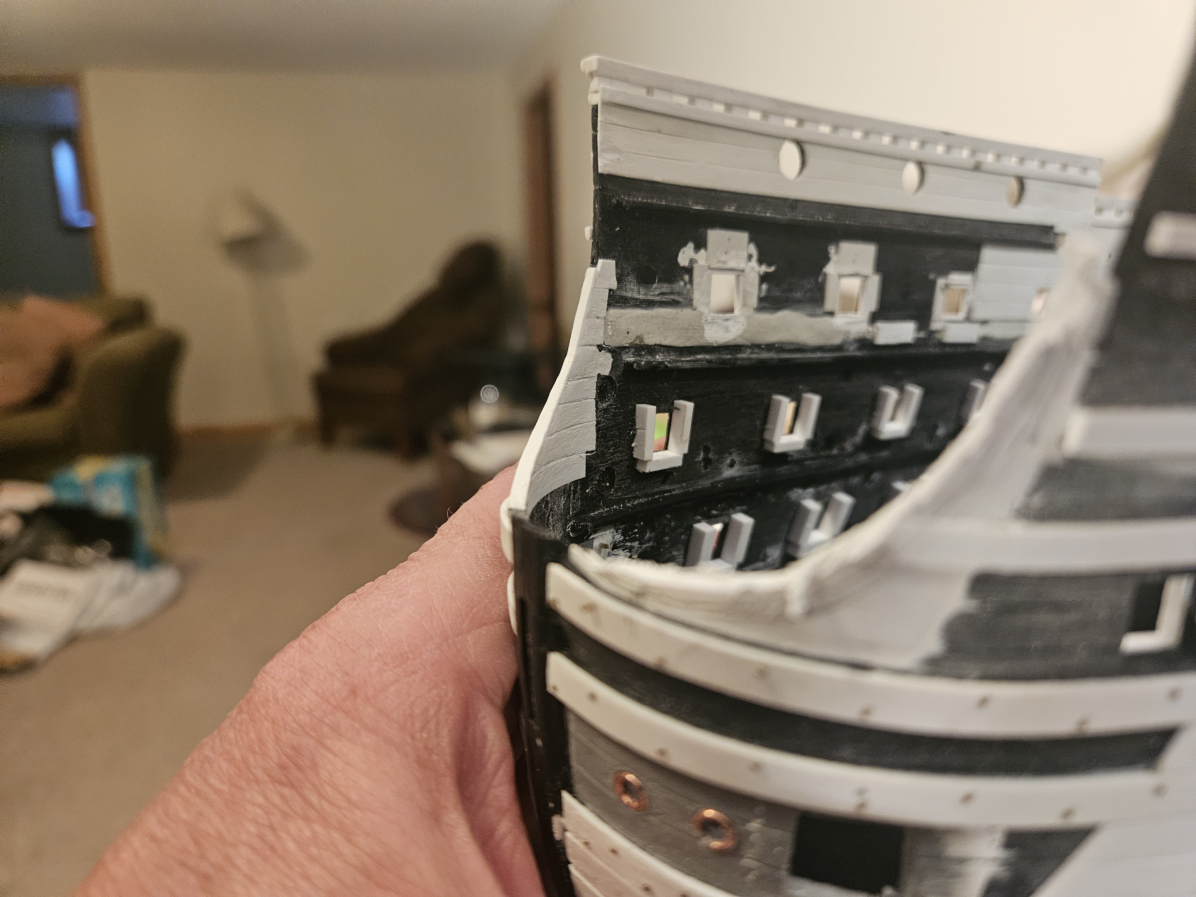
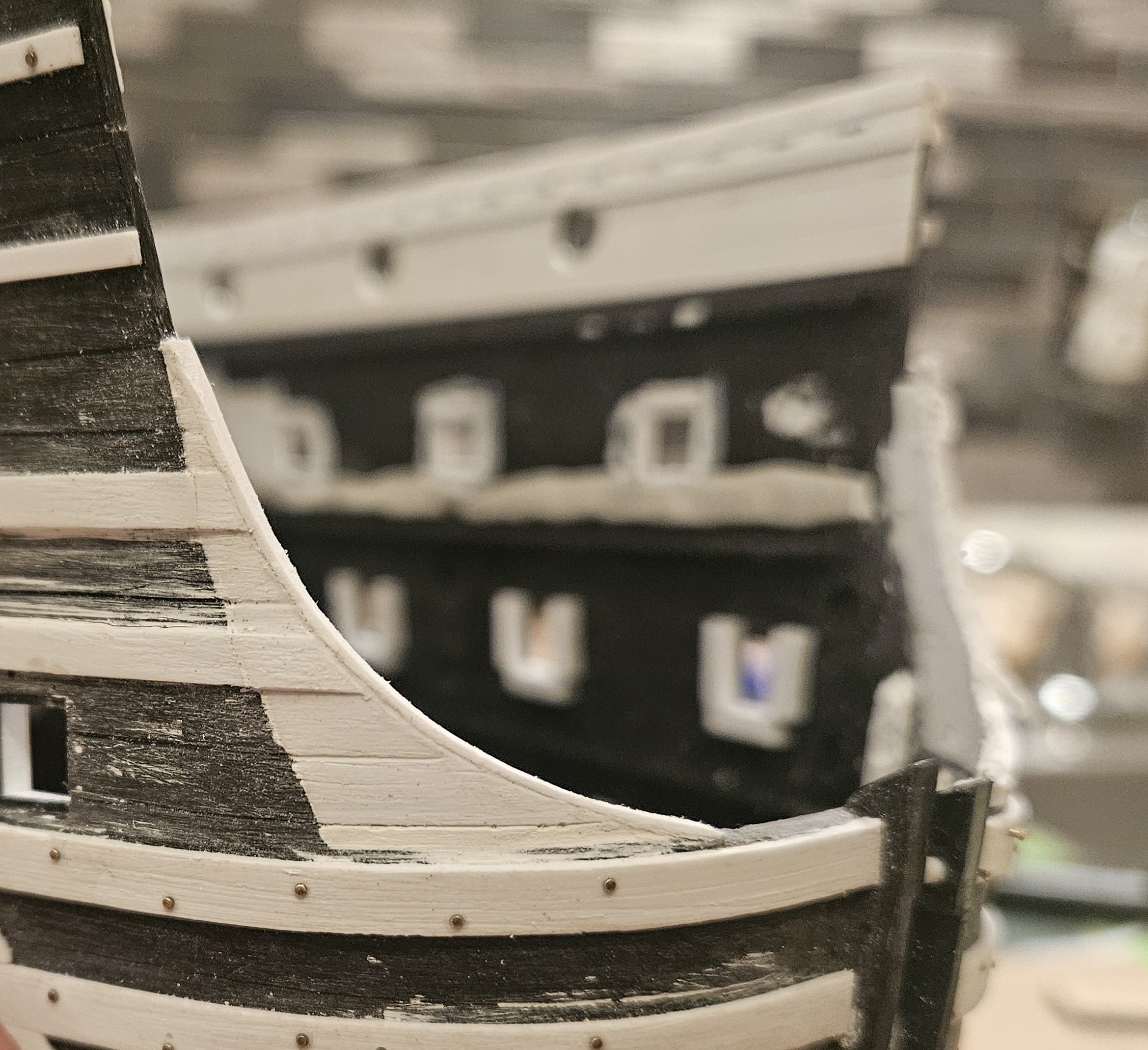
I clipped the hull halves together and made sure that all of the decks and bulkheads fit nicely.... because I planked the inside of the bulwarks with 0.5mm thick planks, I "lost" 1 mm of width that I had to compensate for by trimming away the planking. The nice thing is I don;t have to be incredibly precise, as the weather decks will all have spirketting to cover up any subtle gaps. I also panelled/filled in the last seven timberheads on the last and highest rail. I have seen this look on some drawings, and when I looked at Micheal Saunier's model, I realized that filling in those timberheads would allow me to have the poop royal deck as high as possible; if the timberheads were not filled in, you could see the edges of the poop royal deck halfway up the timberheads. Also, that extra flat surface allows me additional surface area to decorate... Finally, I got a better look at the beak. It looks like I will have to double the thickness of the stem to make it more substantial for the beak. Finally, I am doing a last inspection of every gun port, every wale, every plank line, every copper bolt and bolt head, etc. Better to find and correct now than after the the hull painting.

- 432 replies
-
- 4
-
-
-
- soleil royal
- Heller
- (and 1 more)
-
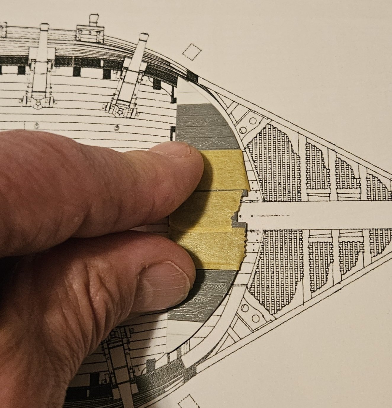
The closer I get to painting the hull.. the more I discover things I want to correct. And I have discovered the beauty of plastic is that you can basically make - and correct! - anything. For example, I naively made an assumption about gun port sizes. The gun ports below are on the upper gun deck; the port on the left is exposed to the elements, and won't receive a lid; whilst the gun port on the right is sheltered bvy the forecastle deck and will have a gun port lid. I assumed gun ports without lids would simply appear larger, as they didn't have rabbeting. Wrong. Well, that's a simple fix with Evergreen and some Tamiya putty. So all gun ports. lid or not, will appear to be the same size. Of course, I then had to drag out the laser leveler and recheck all of the gun ports that I last checked two months ago. I don't think I have seen how other people check for vertical plumb on items like gun ports or fenders, but for me it is extremely fast and easy to use the laser level on a tripod and just move the model gun port by gun port. And of course, I found four gun ports that I didn't feel were true enough on the port side! I just check for vertical plumb, as it seems my eye is good enough to check for, and correct for if needed, horizontal level. The good news is that major surgery wasn't required, just some very light scraping and file work. I would rather find these things that need corrections now then when I am painting the hull!


- 432 replies
-
- 5
-
-
- soleil royal
- Heller
- (and 1 more)
-
Marc, I did it deliberately, but I can't claim I did it for the brainy reason you just offered. I believe my thinking was that IF the lower wales were beefier than the middle wales, and the middle wales were beefier than the top wales (now, is that even true?), then I might want to space the wales a bit further apart as I went up the hull as those lower wales would be so strong, the next wale didn't have to be as close.... again, not even sure if that is a correct way of thinking
- 432 replies
-
- 1
-
-
- soleil royal
- Heller
- (and 1 more)


.jpg.5829d8367523c18fe58ac2b04440fe6f.jpg)