cdrusn89
-
Posts
1,924 -
Joined
-
Last visited
Content Type
Profiles
Forums
Gallery
Events
Everything posted by cdrusn89
-
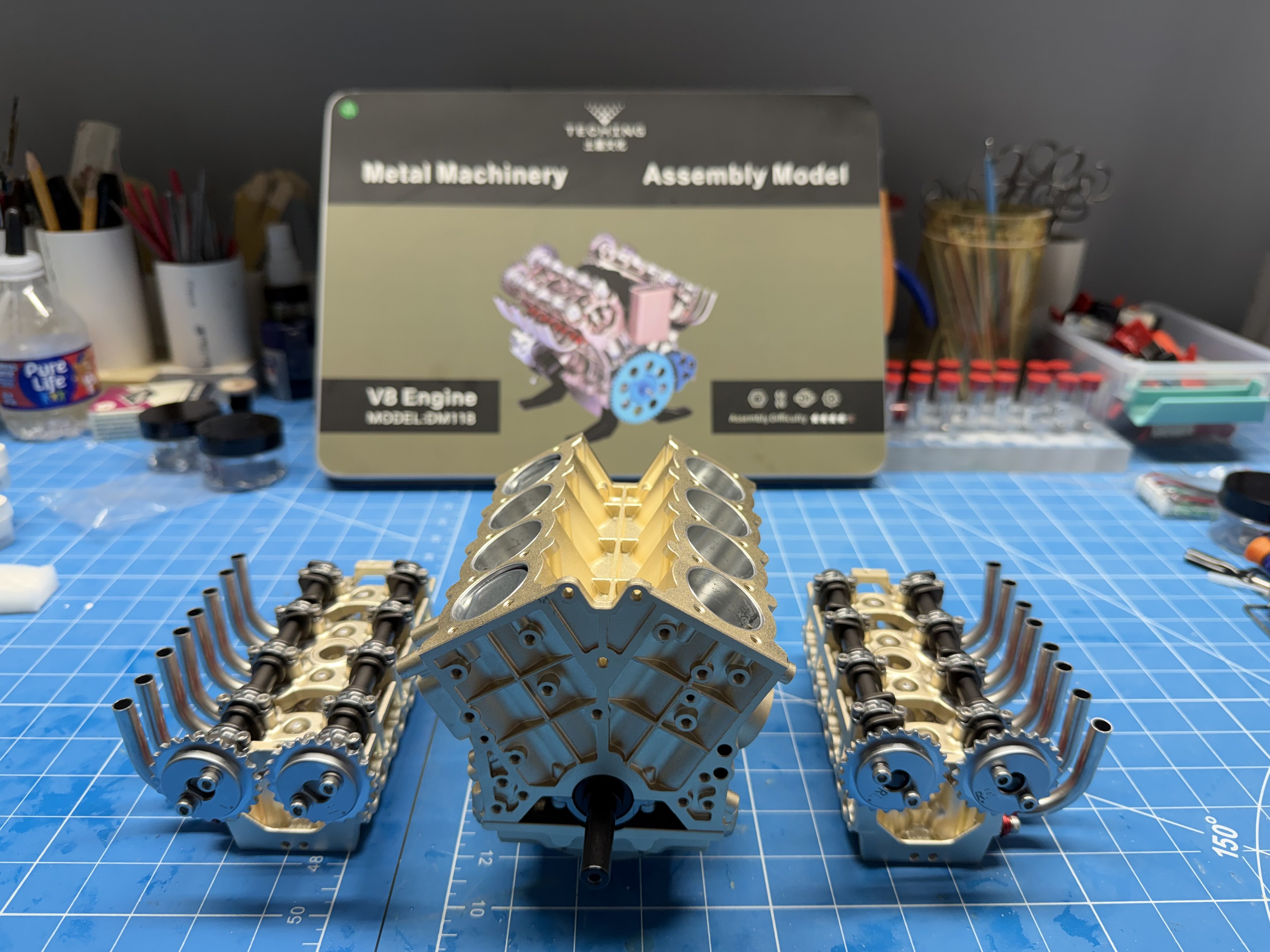
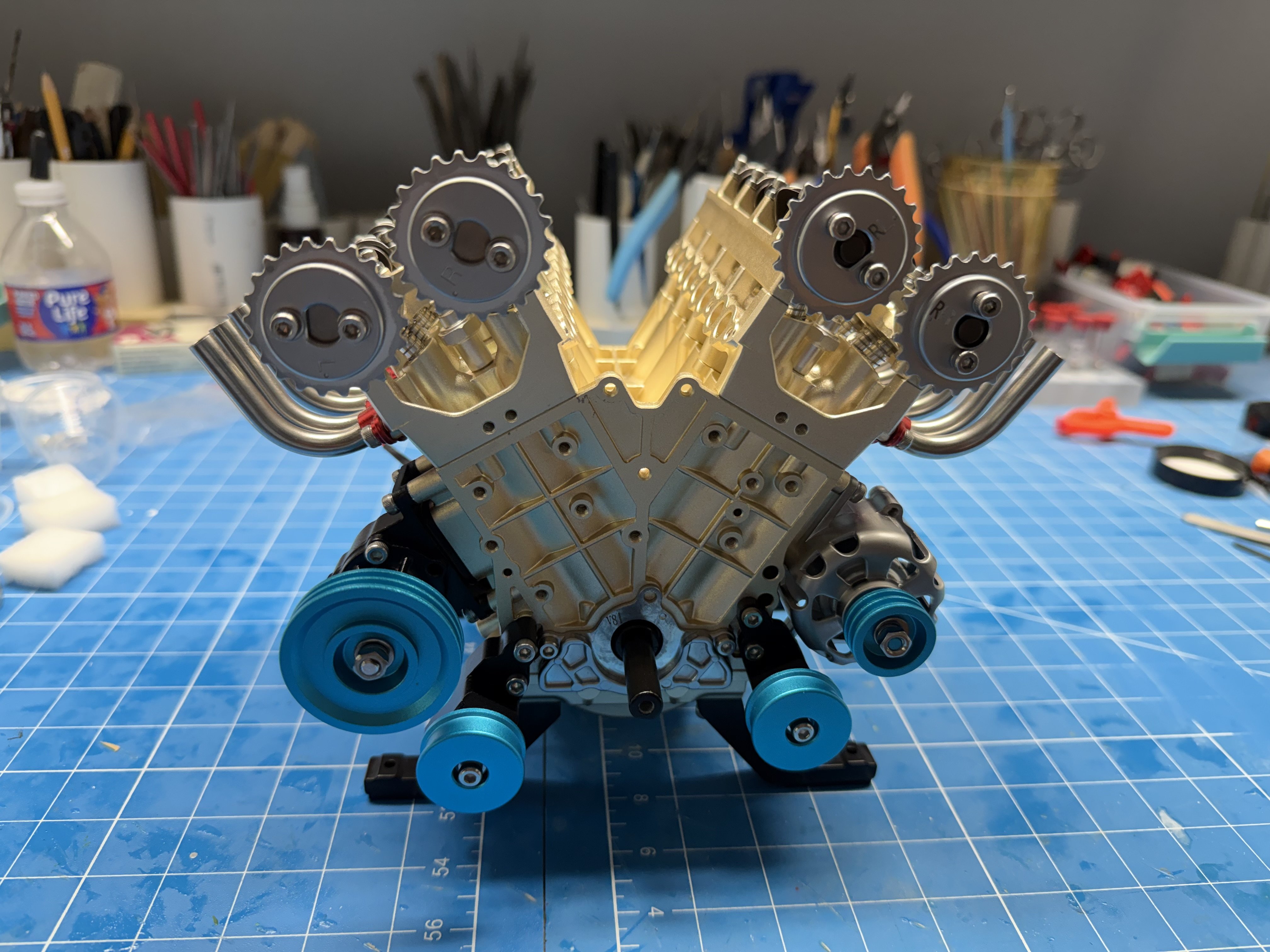
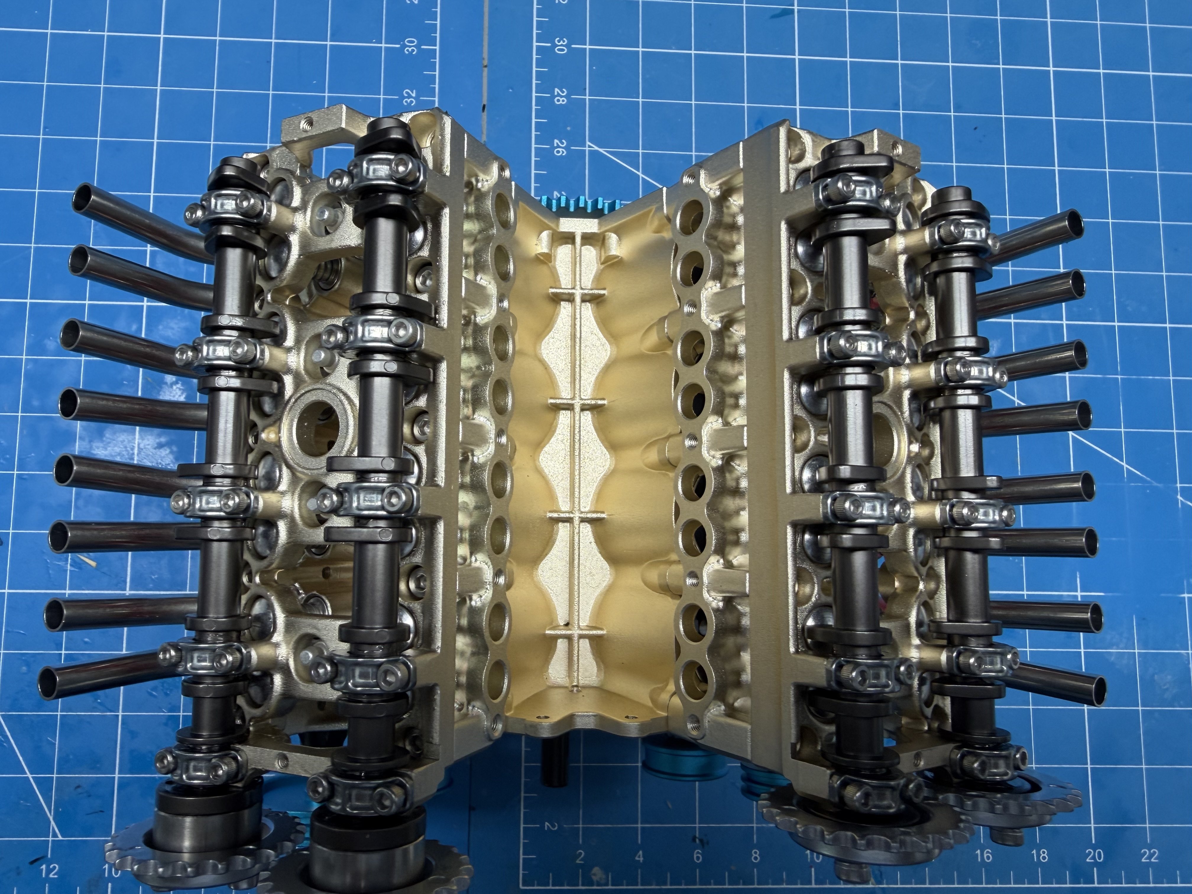
 Terry, Build is finished so here are some pictures of the engine. My wife got it through Micro-mark and it was not cheap but she refuses to tell me how much. Manufacturer is TECHING and yes it is from China. I have the "fun" part yet to come, getting the chain drives for the cams installed and working, then the belt drive for the accessories but everything went together pretty easily so far. Just a bit messy as you have to liberally apply grease to about 100 different places.


-
Thanks Terry - on to my next project - a model of a dual overhead camshaft V-8 engine, all in metal - and it "works".
-
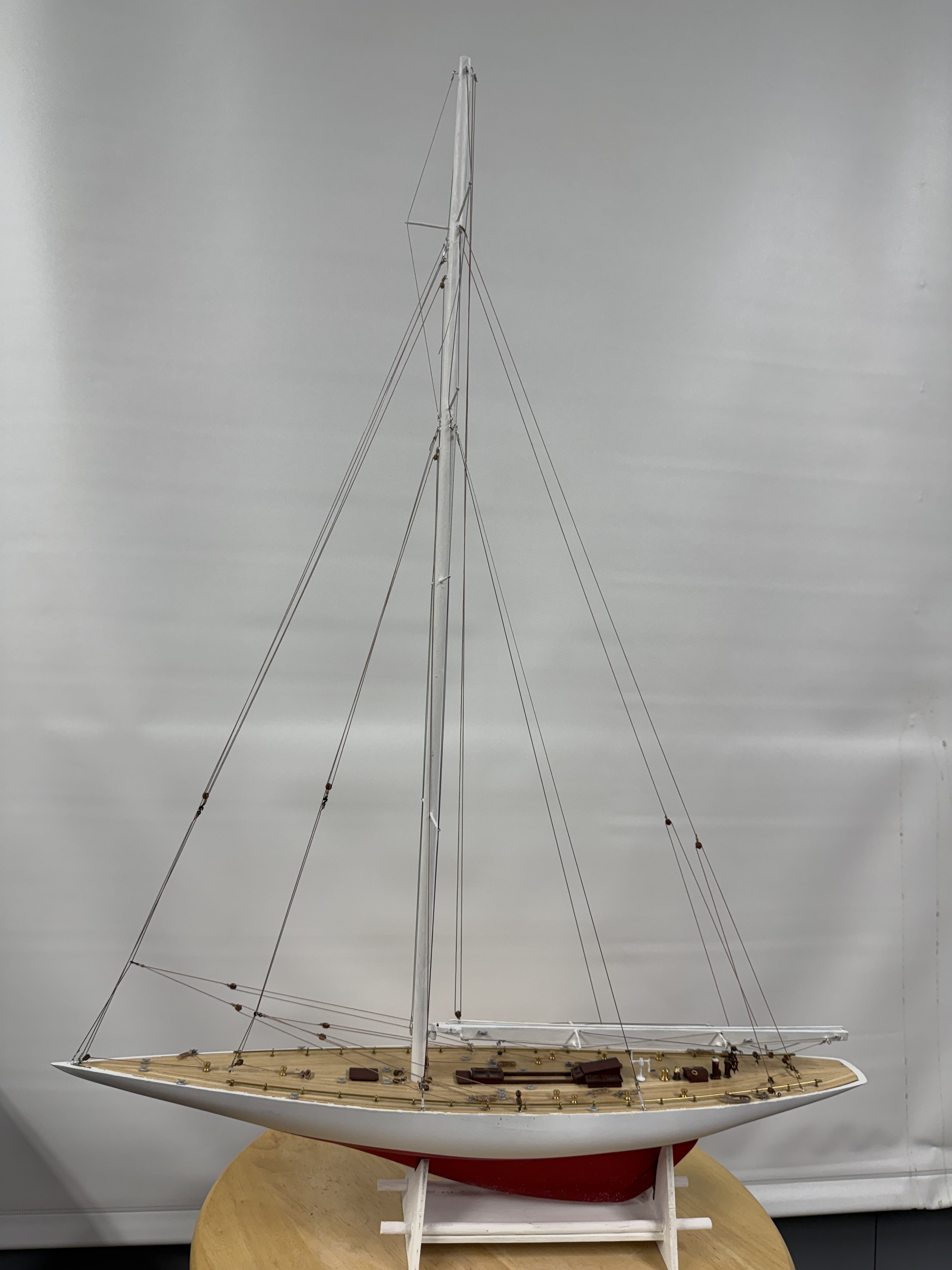
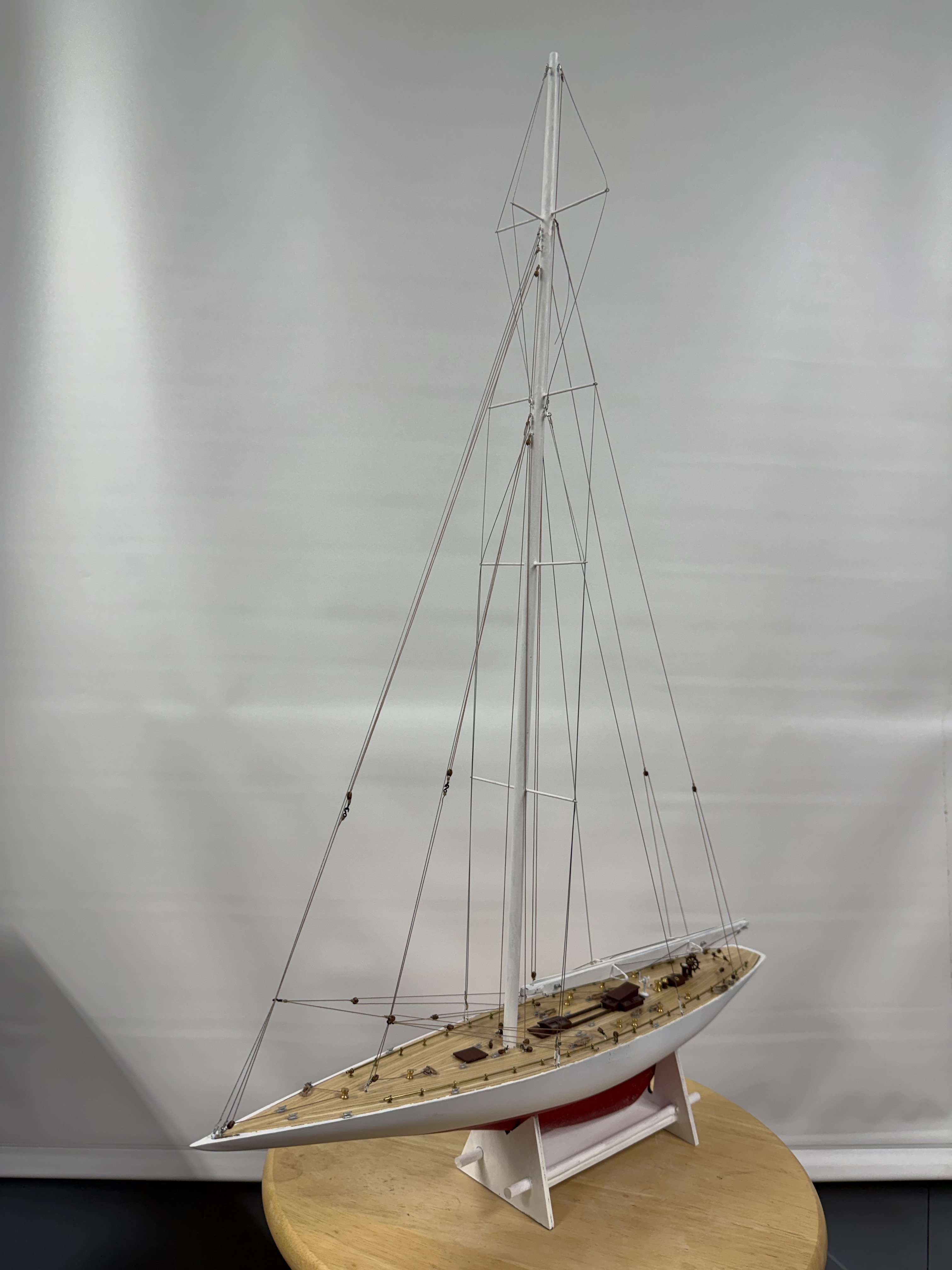
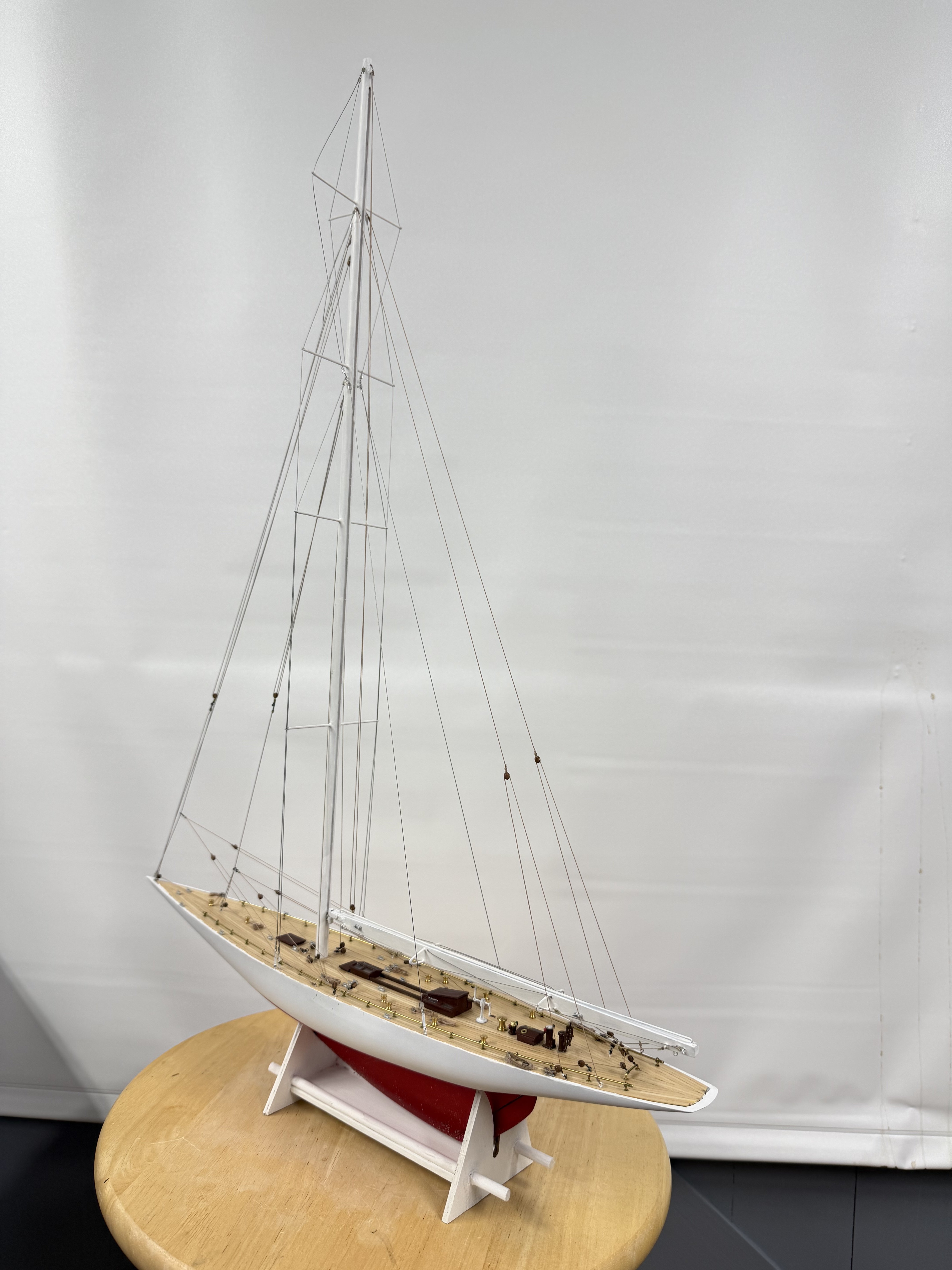
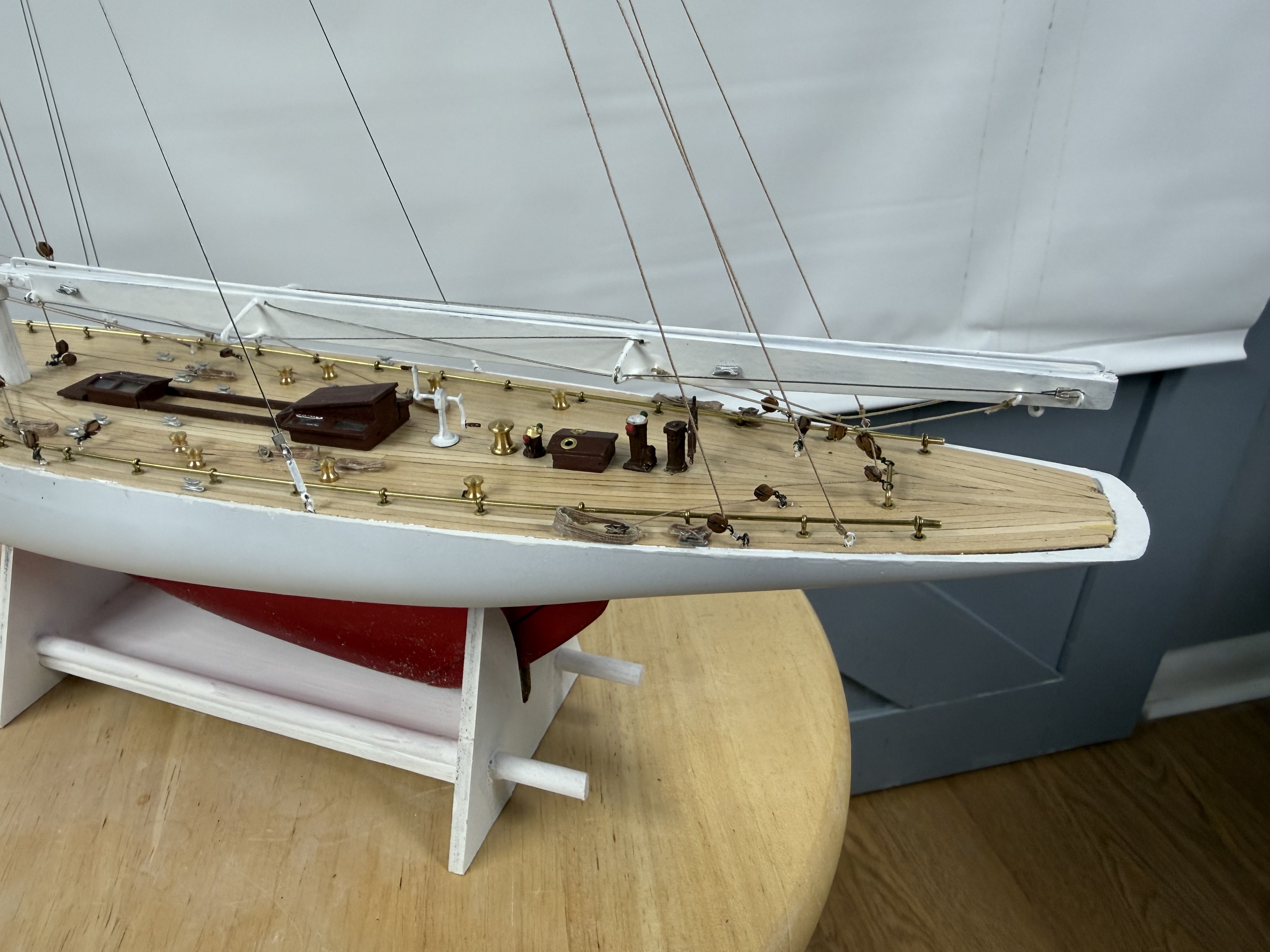
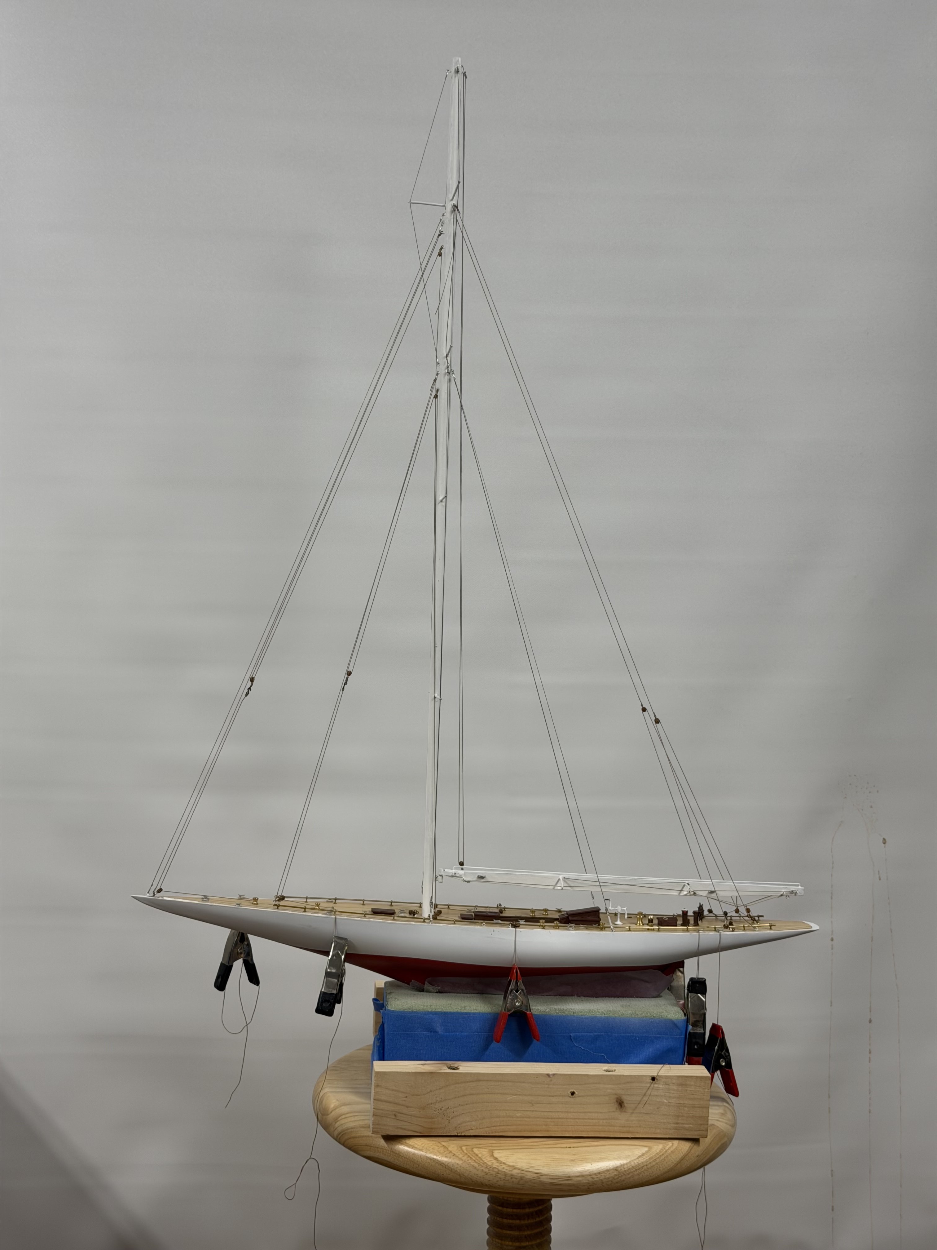
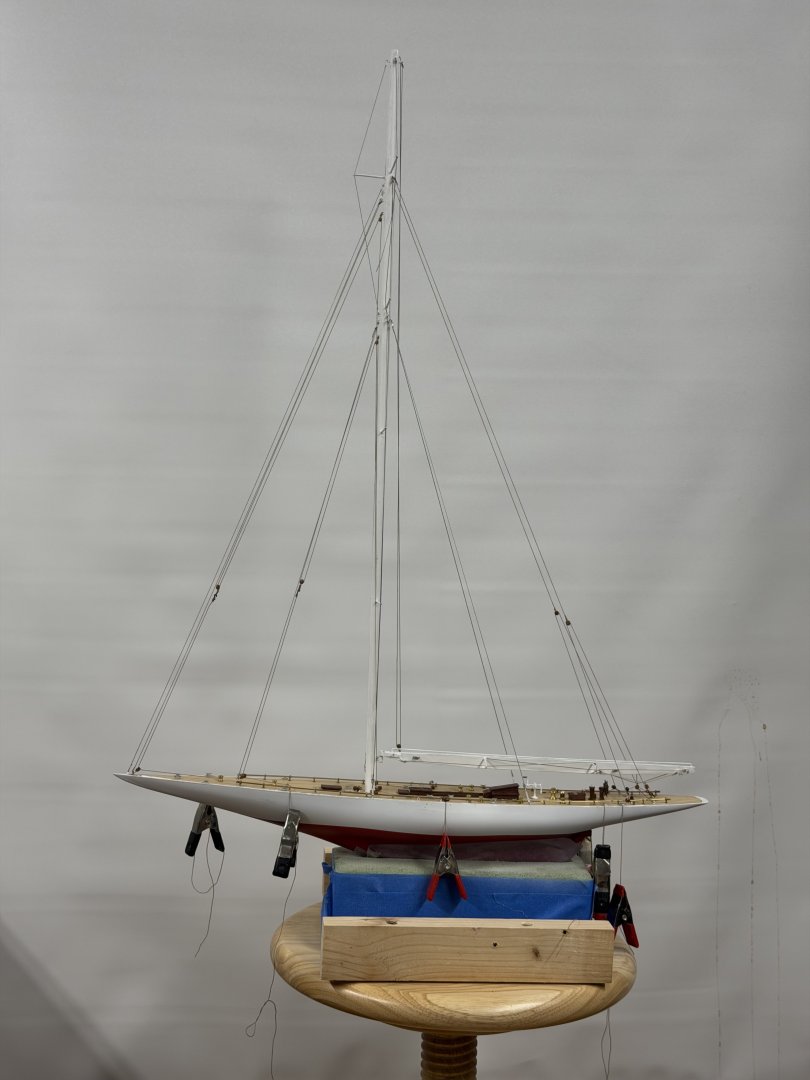
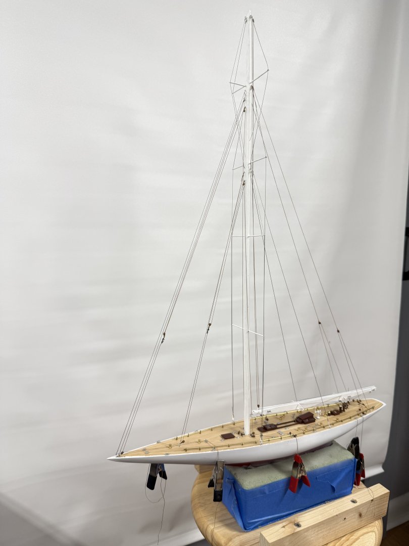
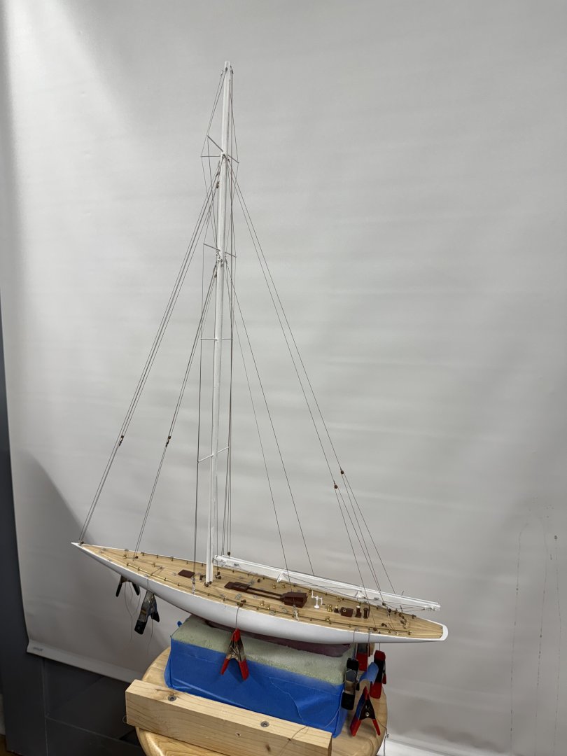
Almost done. I have to add the sheet tackle for the jibs and figure out what i am going to do for the rope coils on deck. I put together that base in the kit, added a reinforcing piece on the bottom and painted it flat white. It will need another coat, maybe two. Here is how she looks at the moment. The clips are holding tension on the rigging lines as none of the running rigging has been secured at the deck. If I remove the tension the jib halyards will twist themselves in knots so keeping the tension is important (to me).

-
Rick - no, the blocks are from Model Expo 3mm "Beautiful Blocks". They are real wood. I have not looked recently but the Syren 3-D Printed blocks I got awhile back were not a "pleasing" color IMHO.
-
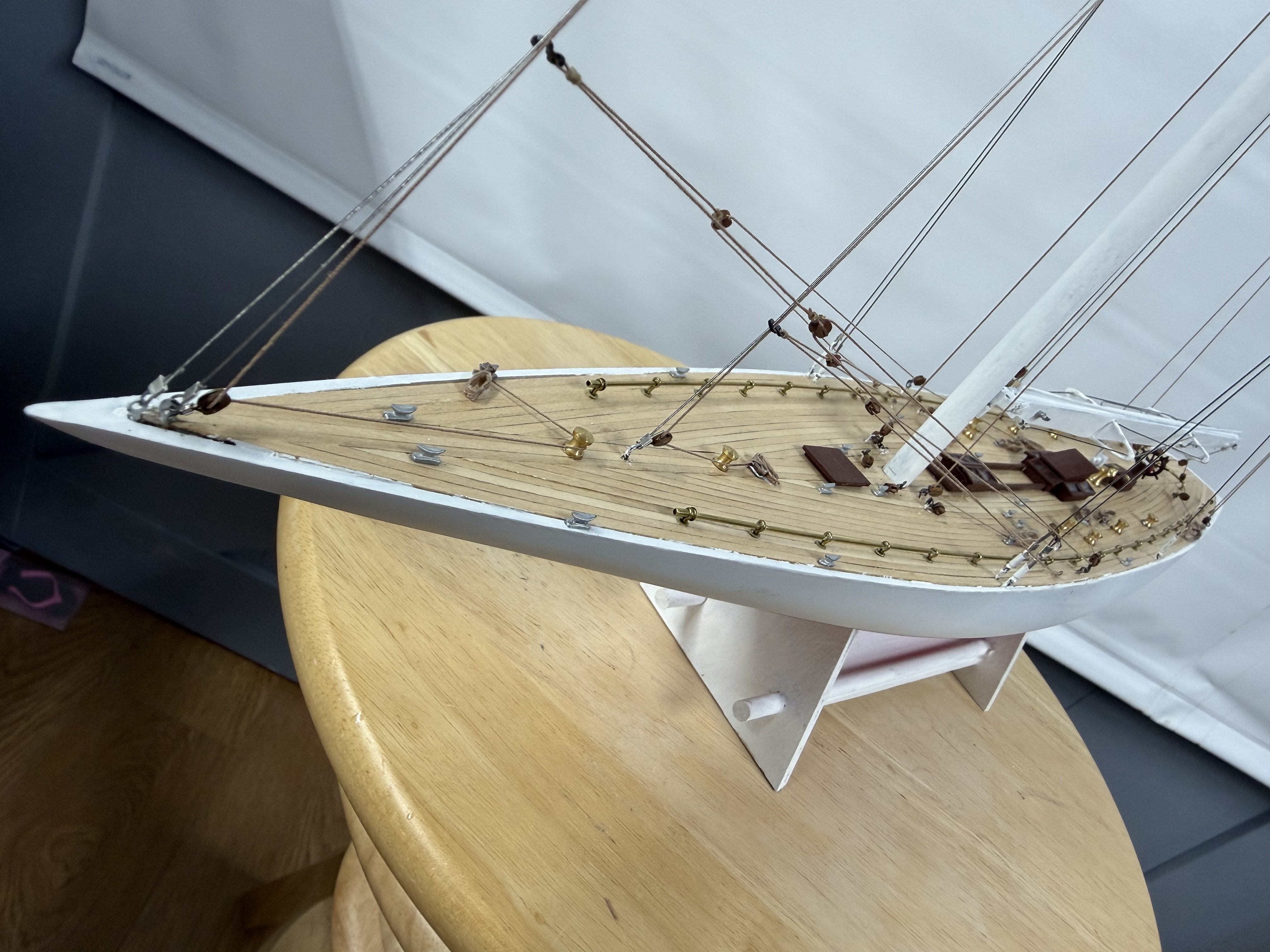
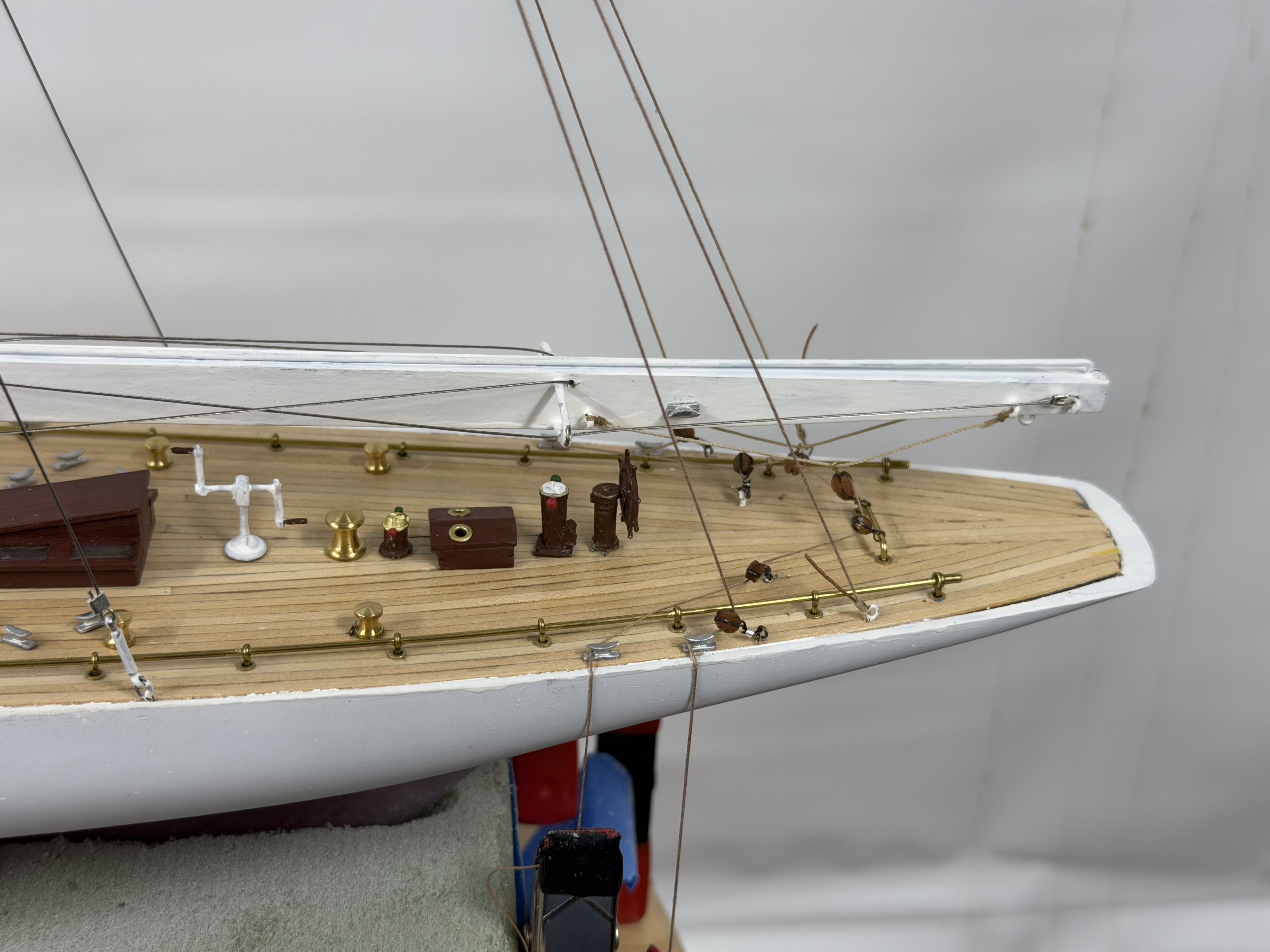
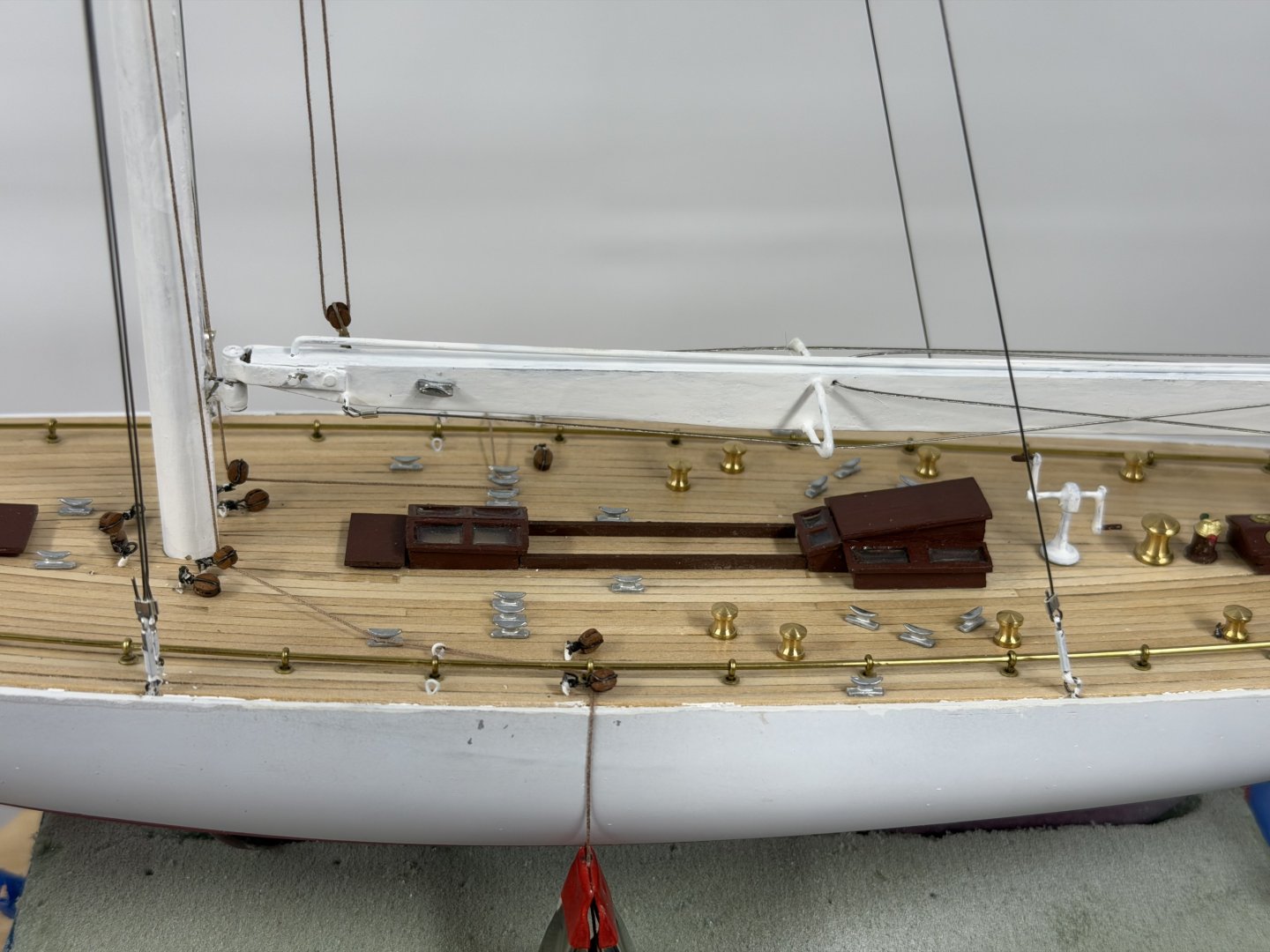
Except for some of the more vulnerable components (wheel, compass and winch) all the deck components are in place. Working the rigging on the masts/boom before adding the mast and setting the standing rigging.
-
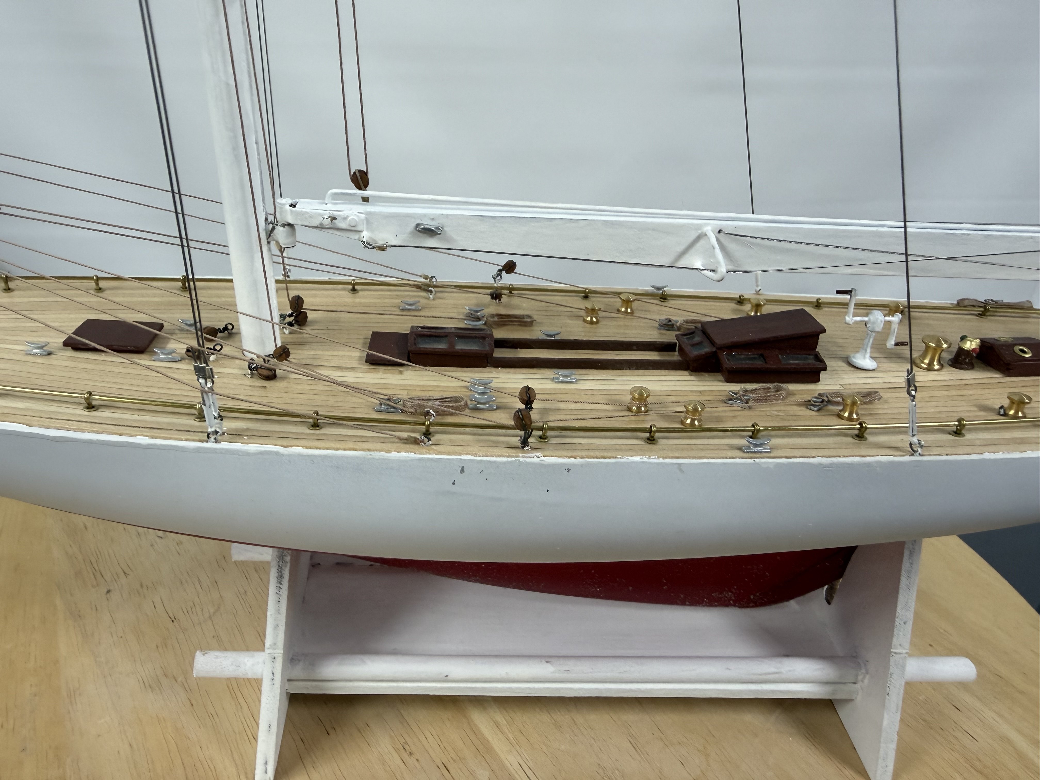
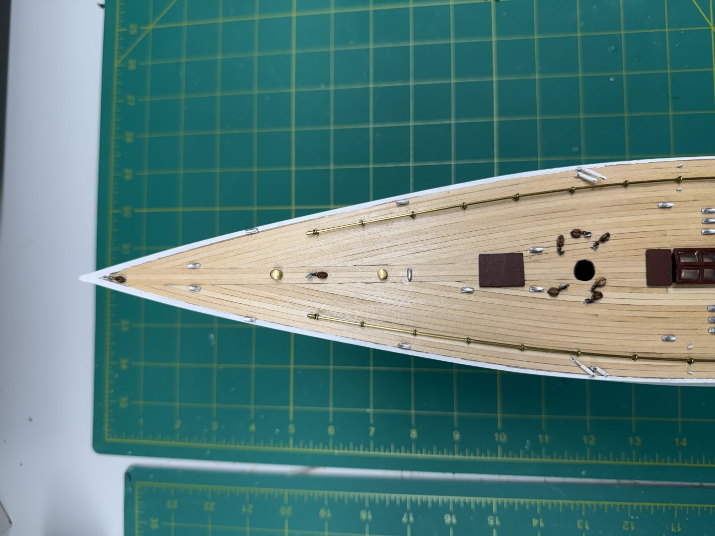
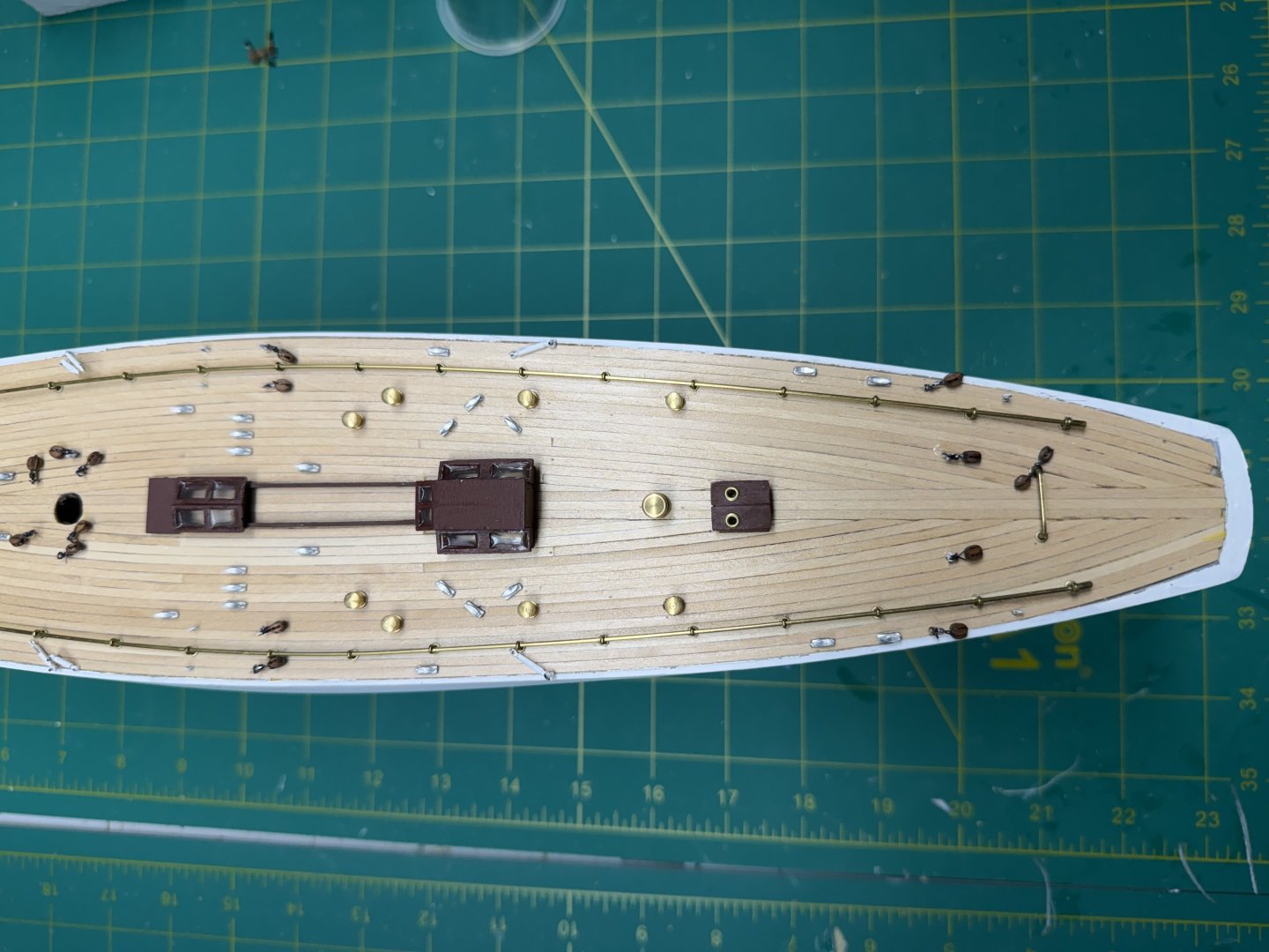
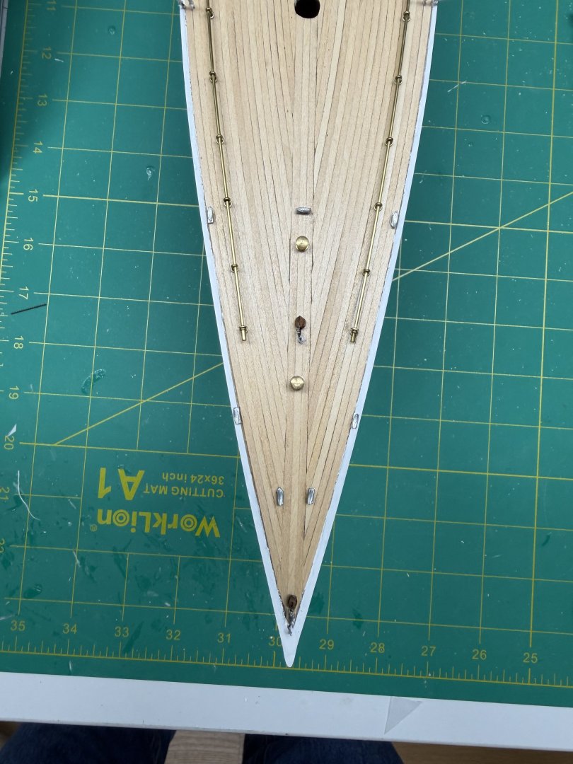
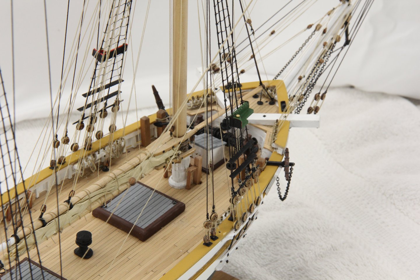
Populating the deck hardware (and the structures when I get that far aft). Here is the progress so far.
-
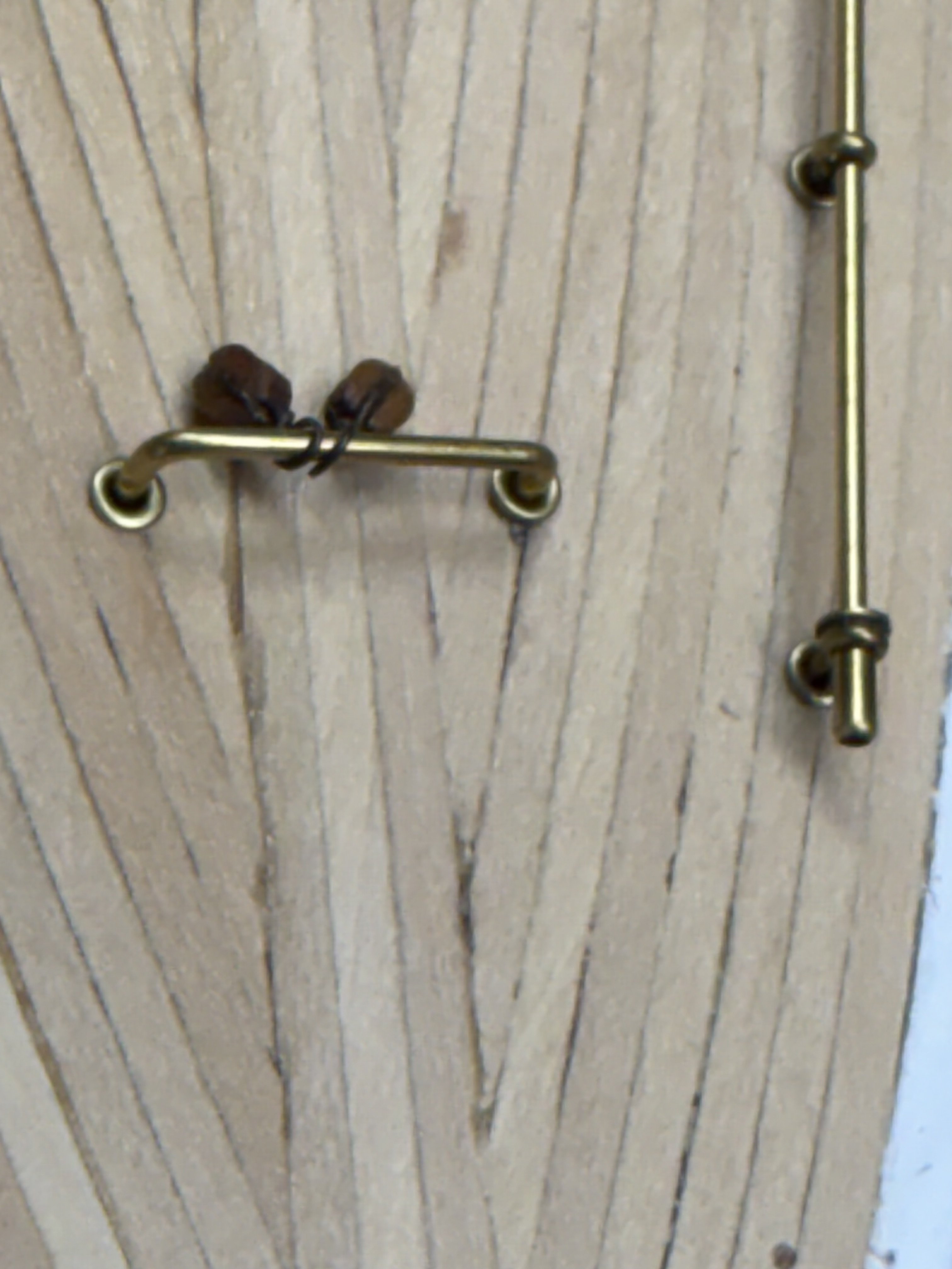
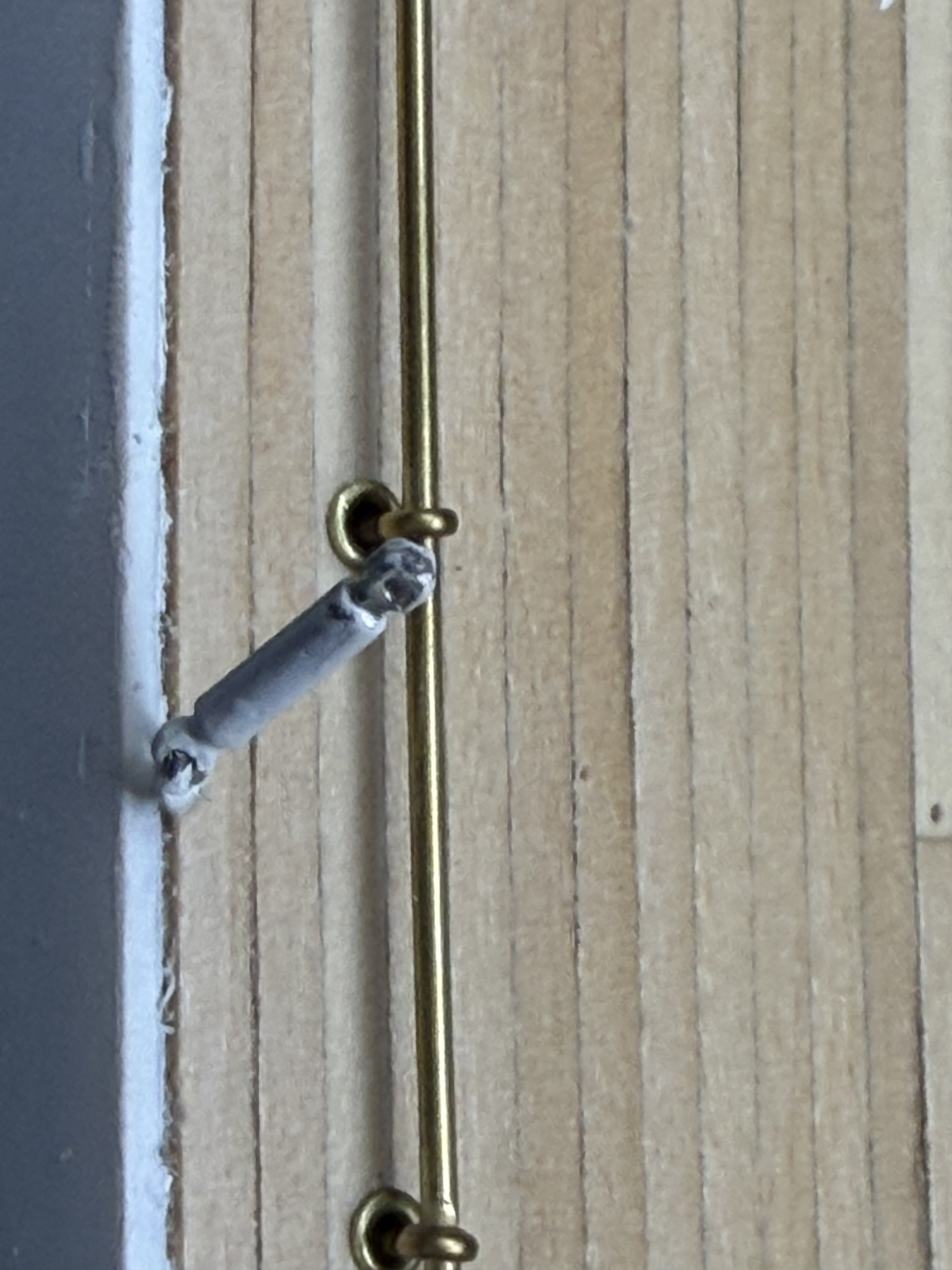
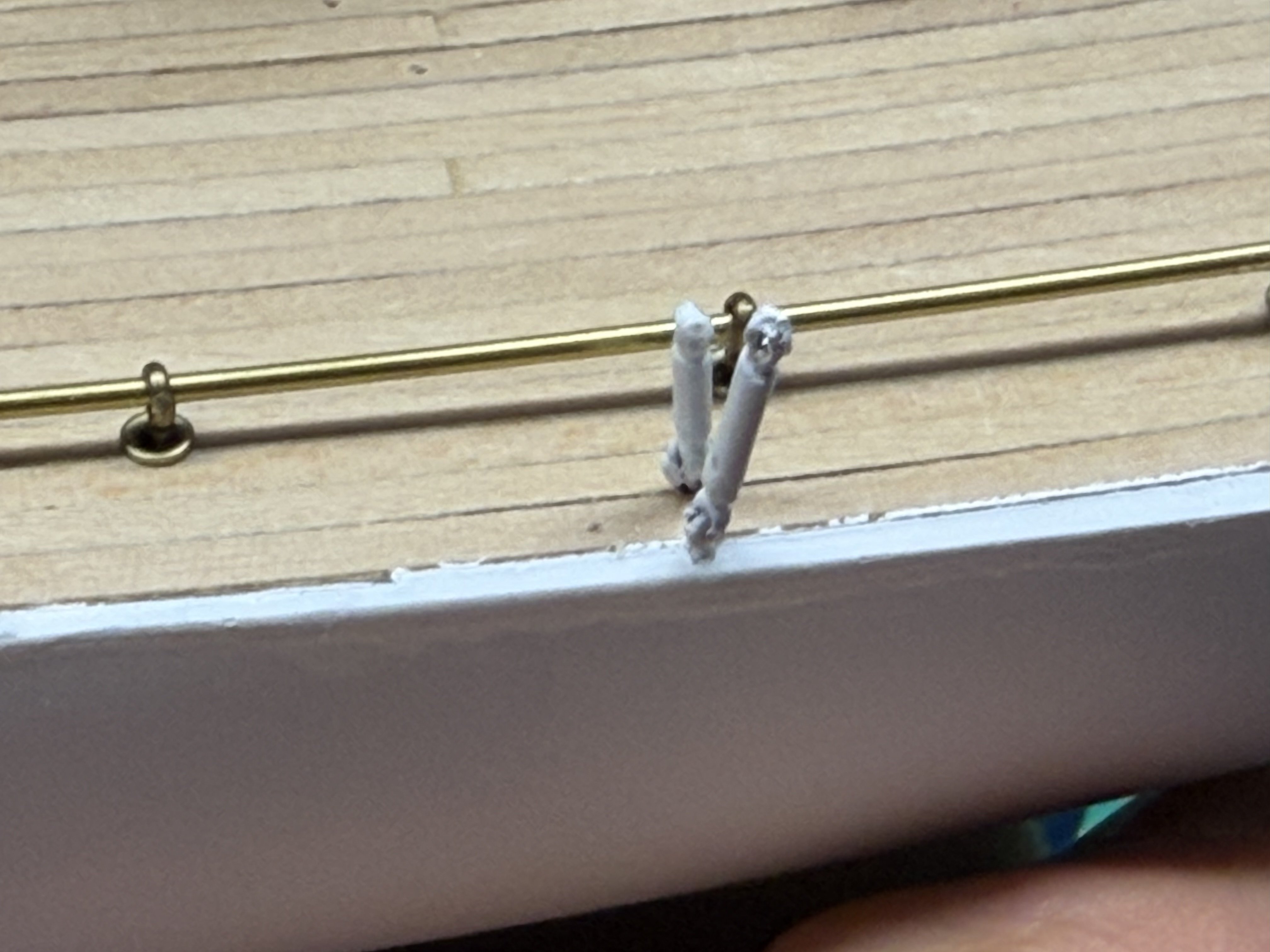
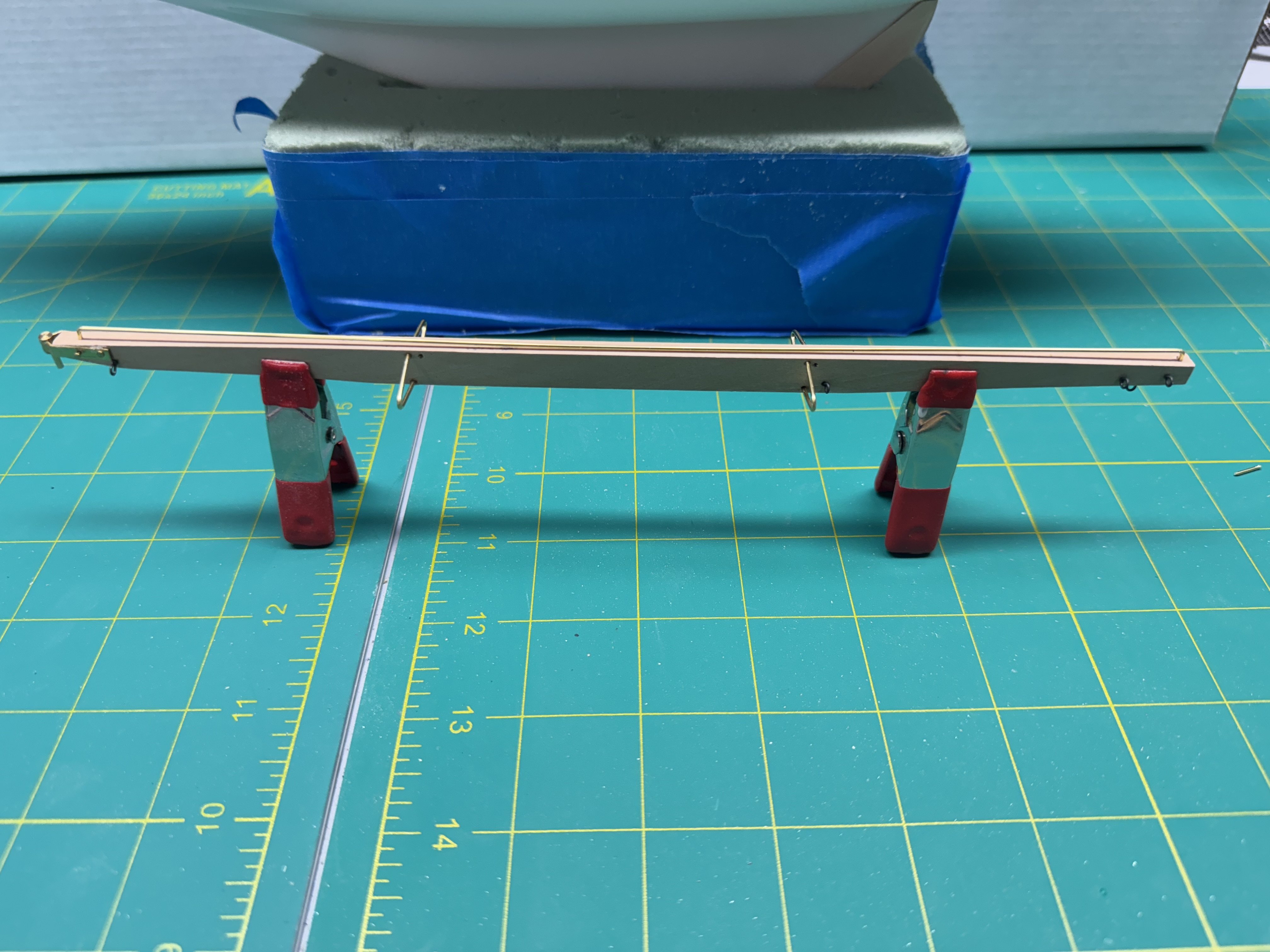
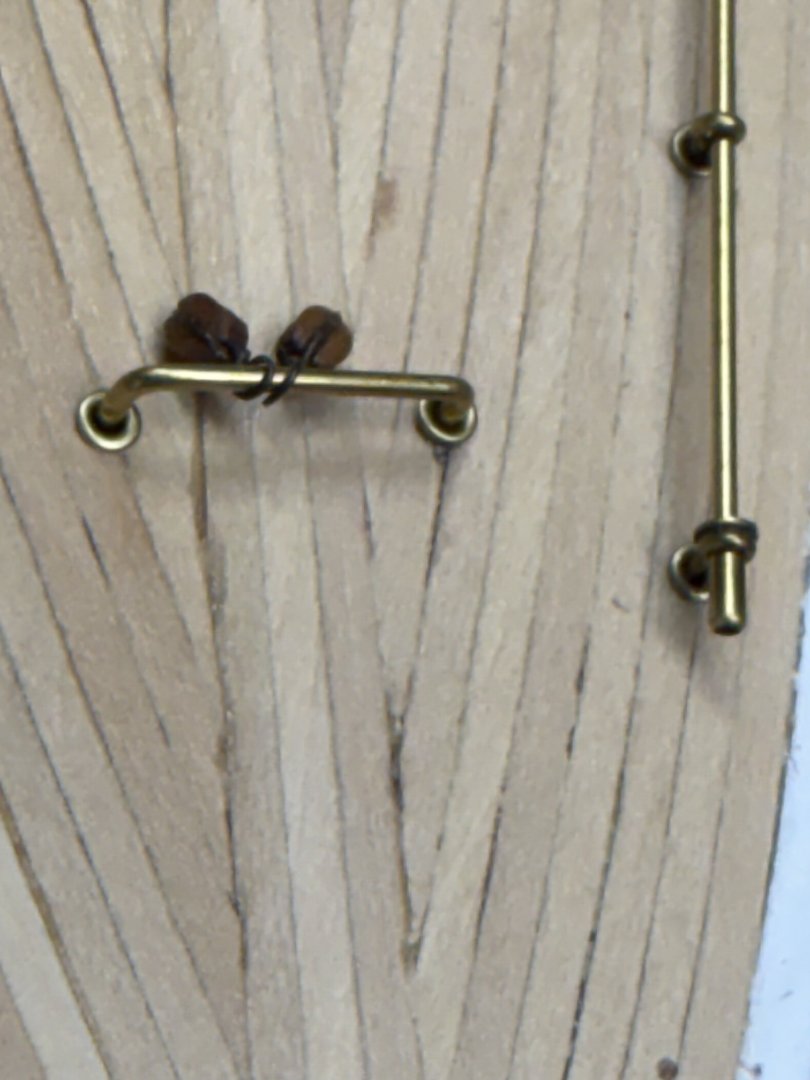
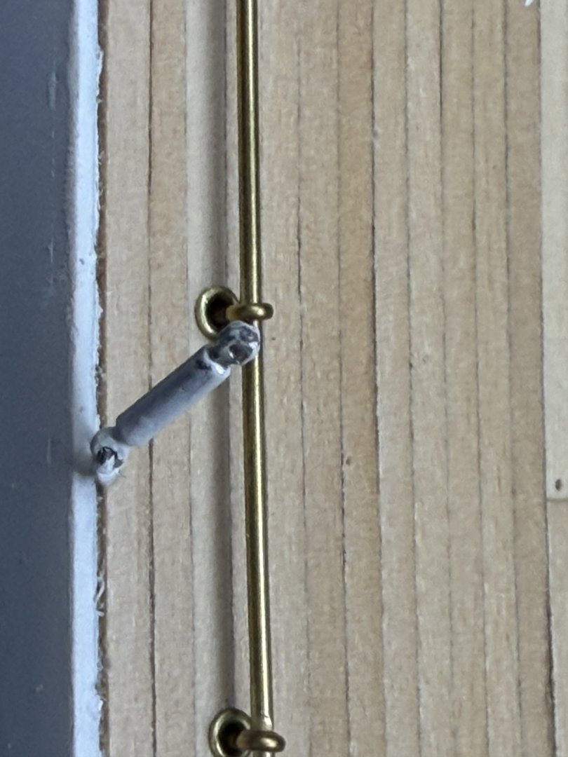
I have to boom pretty much ready to "go", still need to add the blocks for the main sheet tackle but I need to figure that out first. Drawing/instructions are not all that clear. I did manage to fabricate the main sheet traveler and the two blocks that go there. For the main mast stays the terminate abeam the mast I decided that they probably had some type of adjustment mechanism so I added two sizes of Britannia metal turnbuckles to the eyebolts. I used to different length turnbuckles so that the termination of the two stays are not right next to each other.I had to make my own eyebolts as the kit provided ones would be a real challenge to use close to the outer edge of the hull. I also added a turnbuckle to the eyebolt where the back stay terminates - the instructions provide for this too but not the ones abeam the mast.

-
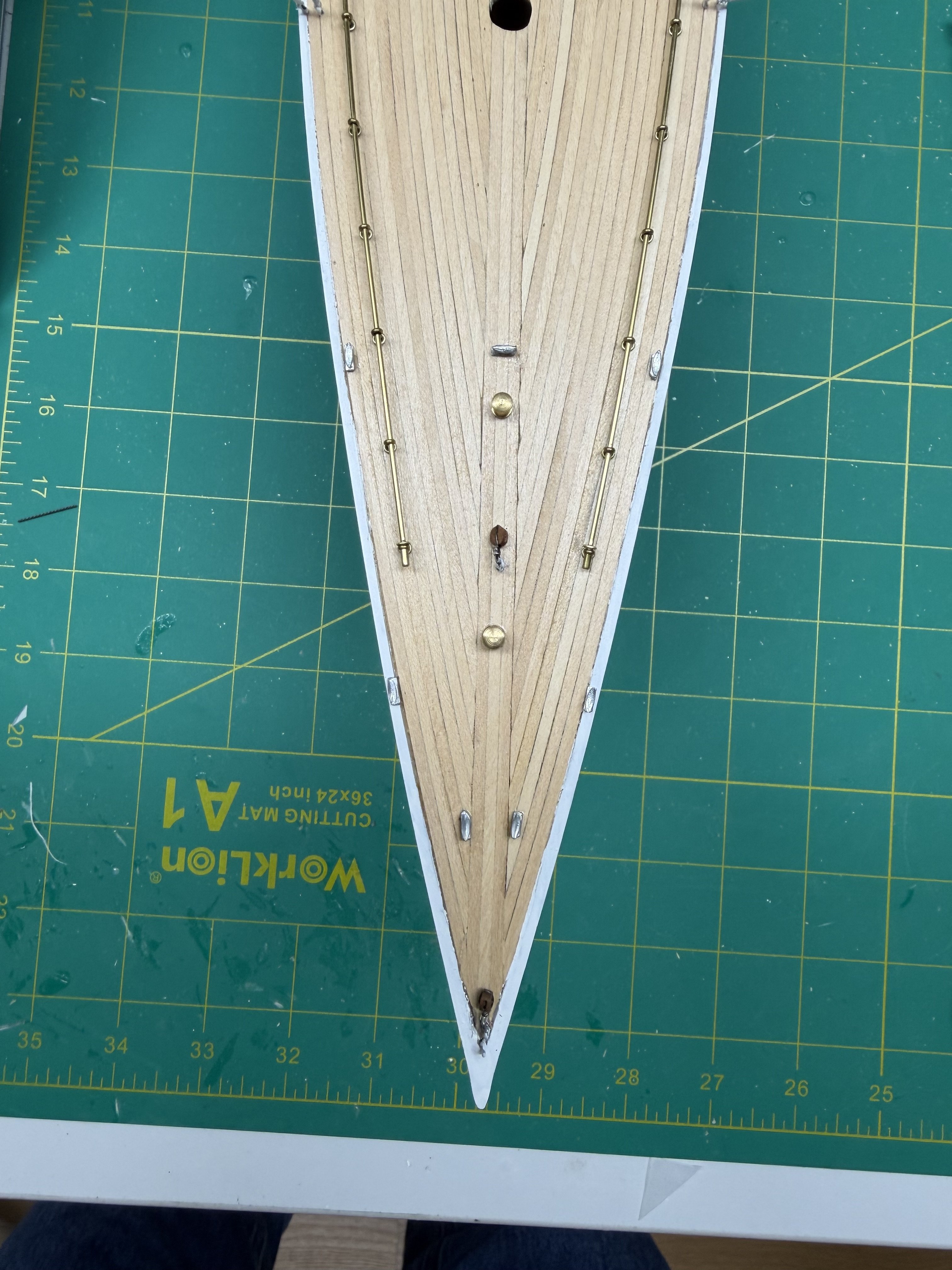
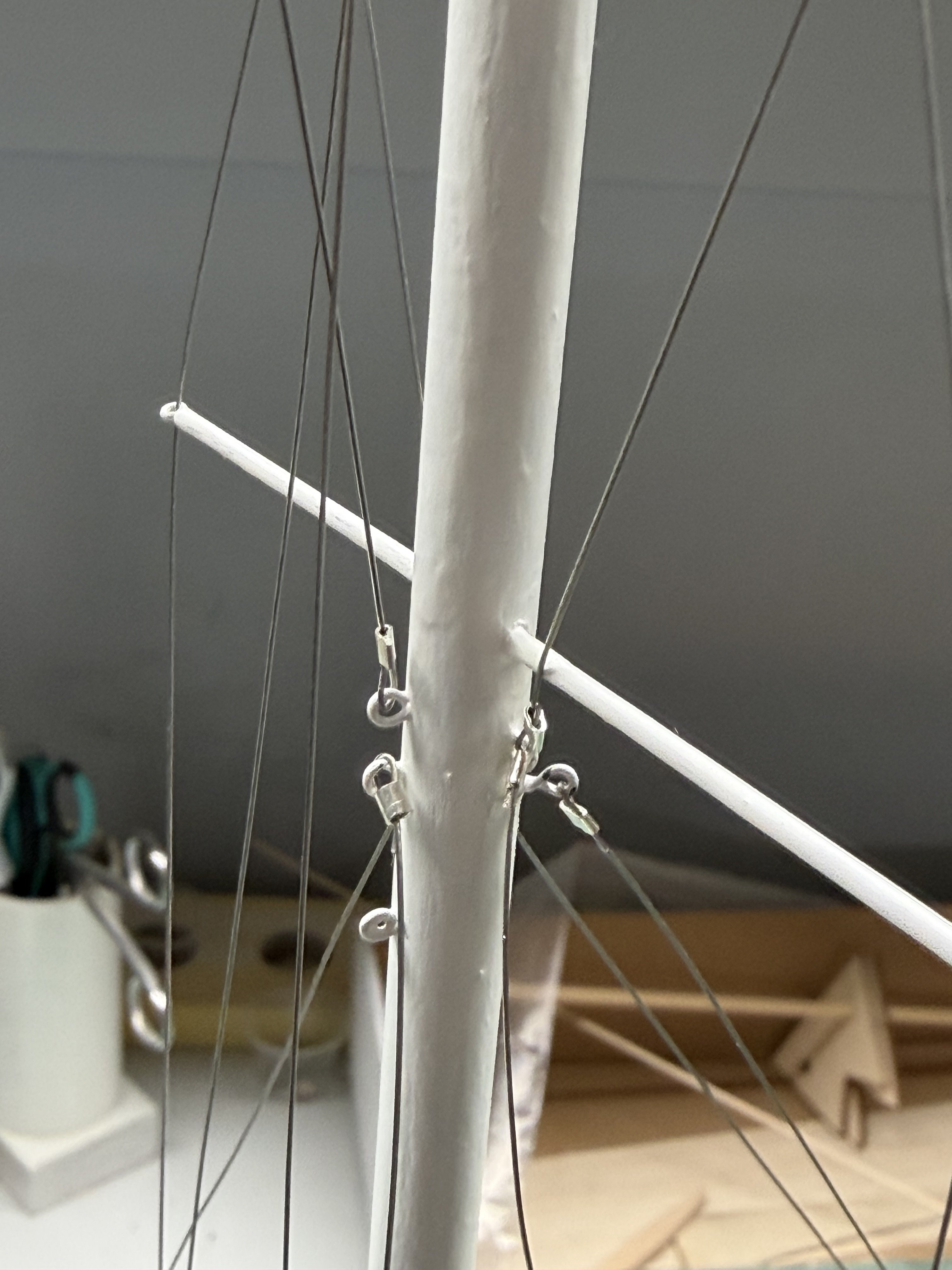
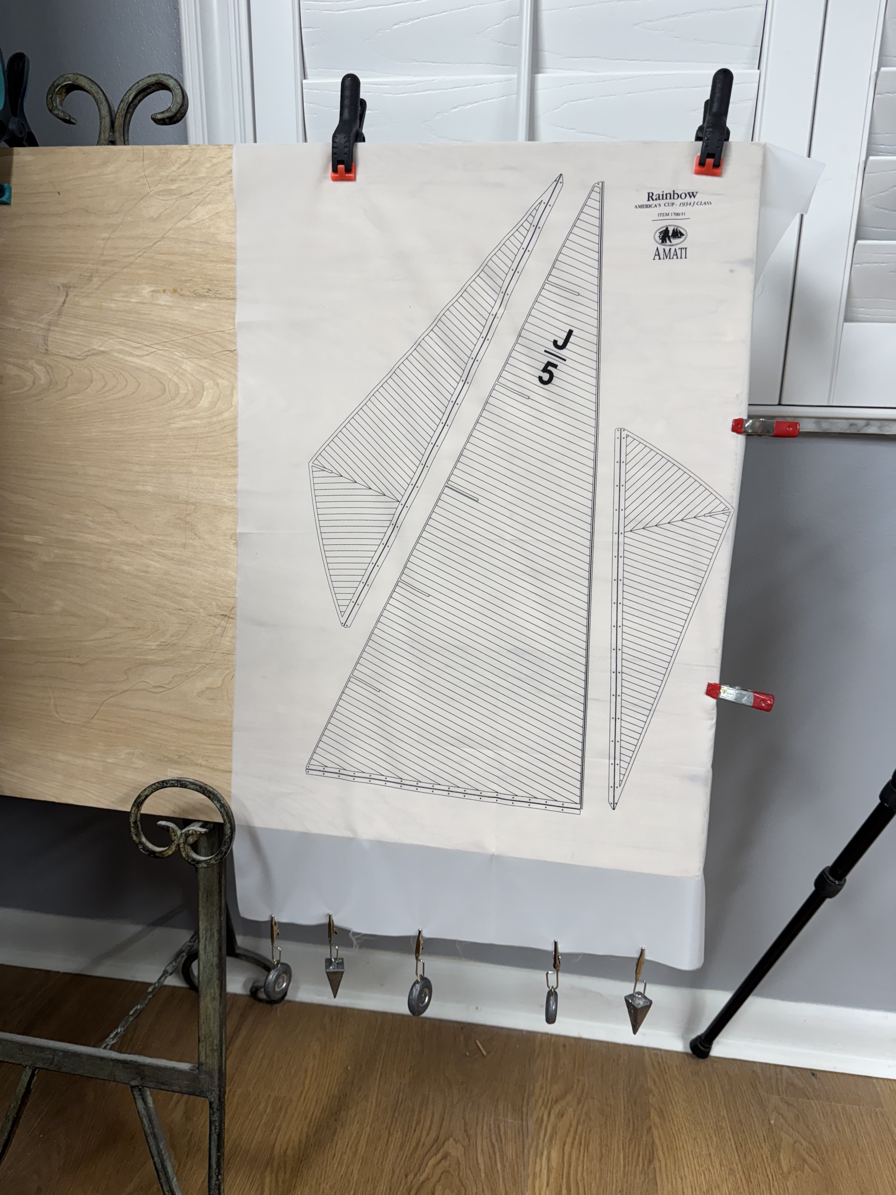
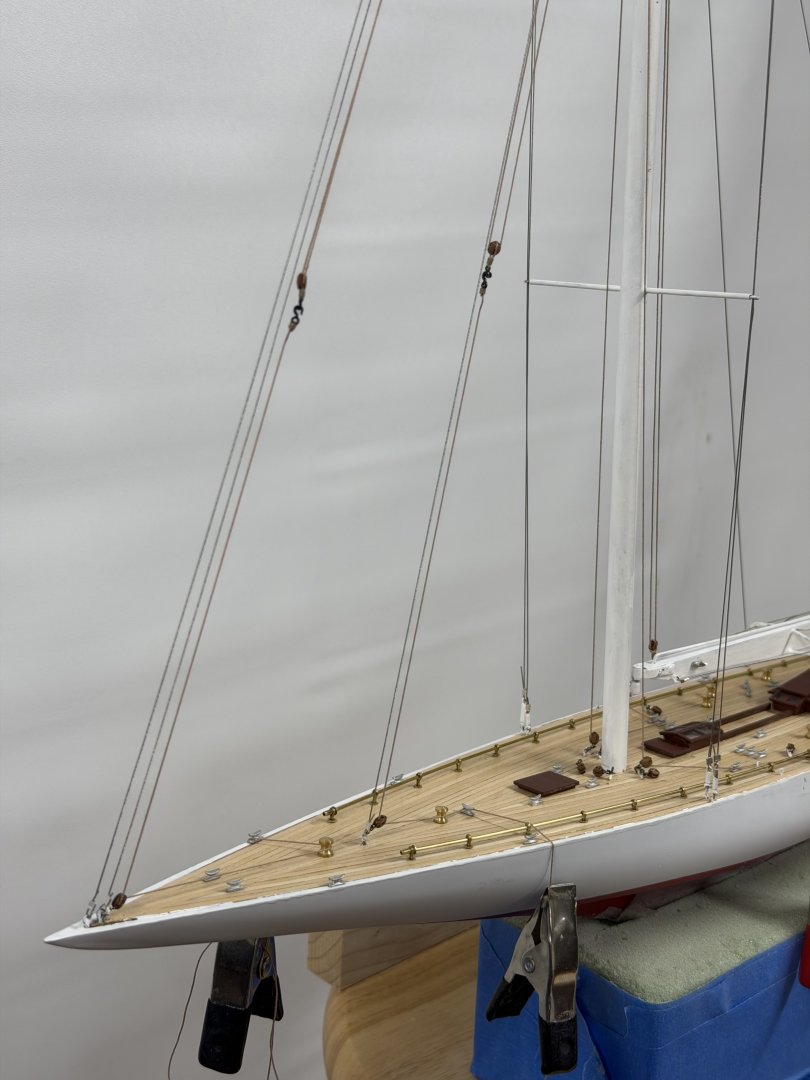
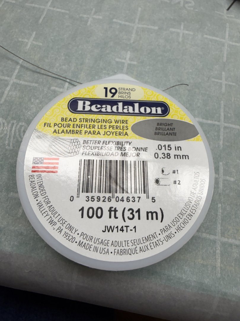
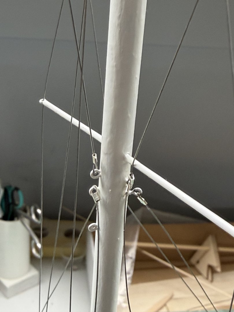
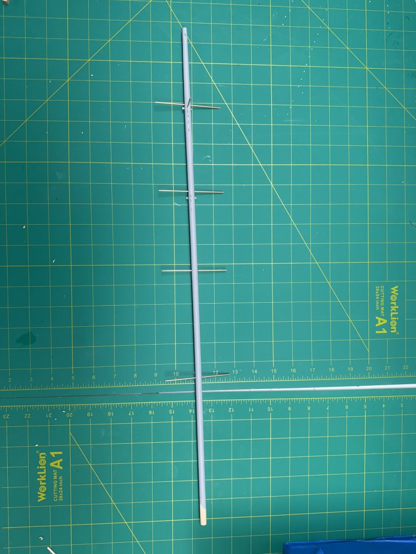
After a 9 month "sabbatical" from model ship building "I am back". Having given it some thought while pursuing "other tasks" I decided to not use the provided sails and just show the model without sails. The ones provided are not really to scale and I have not figured out a methodology for attaching the ropes that does not result in the sail edges having at best an unsightly appearance. I think she will look fine "nude". I will have to fabricate a boom rest since there is no topping lift and I can't imagine that a removal boom rest was not part of the rainbow equipment list. With the hull and deck now complete it is time to start populating the fittings on deck. But before tackling that I decided to get the stays and such installed on the mast and boom. Instead of using the provided "rope" for the standing rigging I decided to use silver "Beadalon" jewelry wire. I used the .015" (.38mm) wire as that is close to the size of the provided line and looks "okay" on the model. I have assumed that the actual standing rigging on Rainbow was wire not rope. Here is a shot of the wire in place on the mast. By my count there are 12 pieces of standing rigging that attach to the mast. I have them all done now and am working on the boom.
-
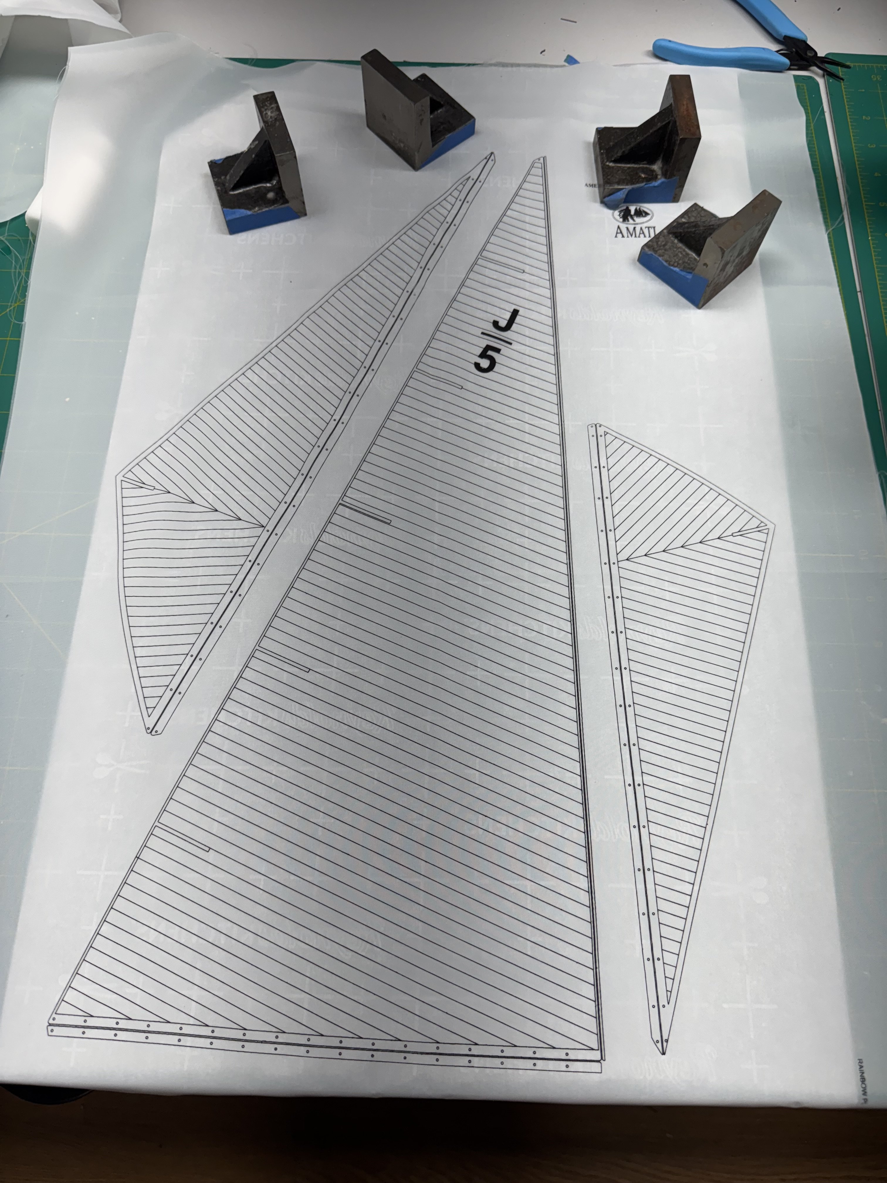
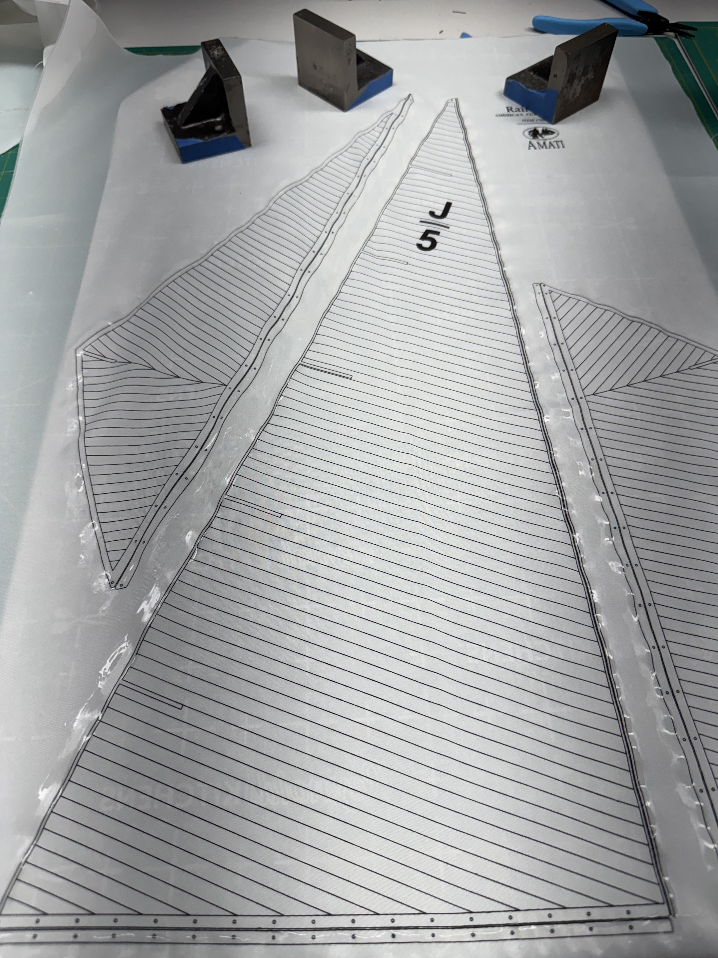
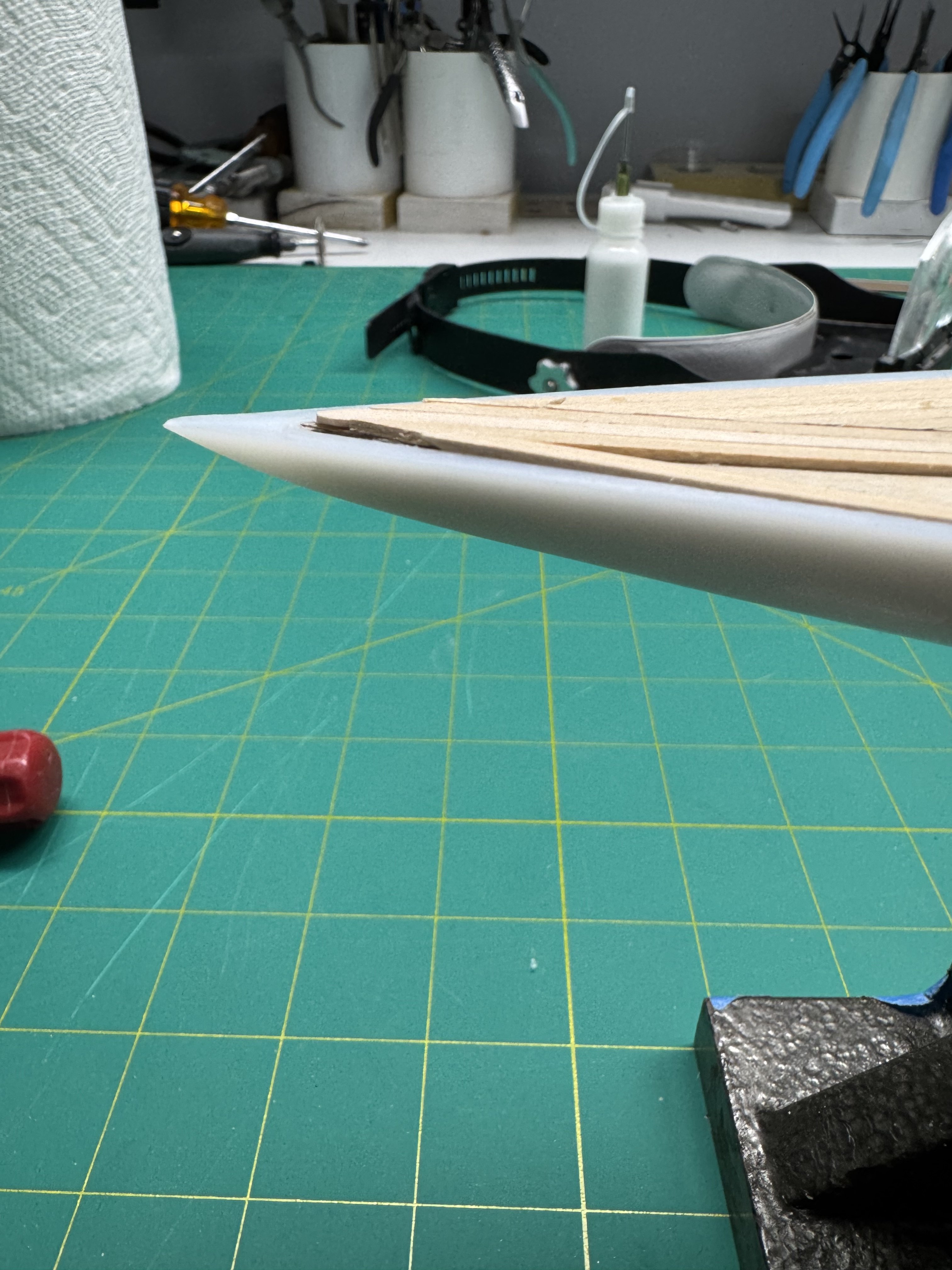
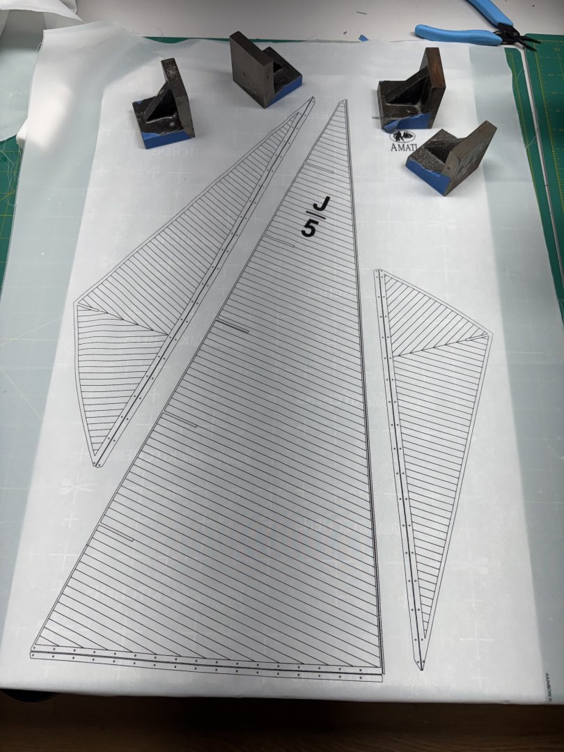
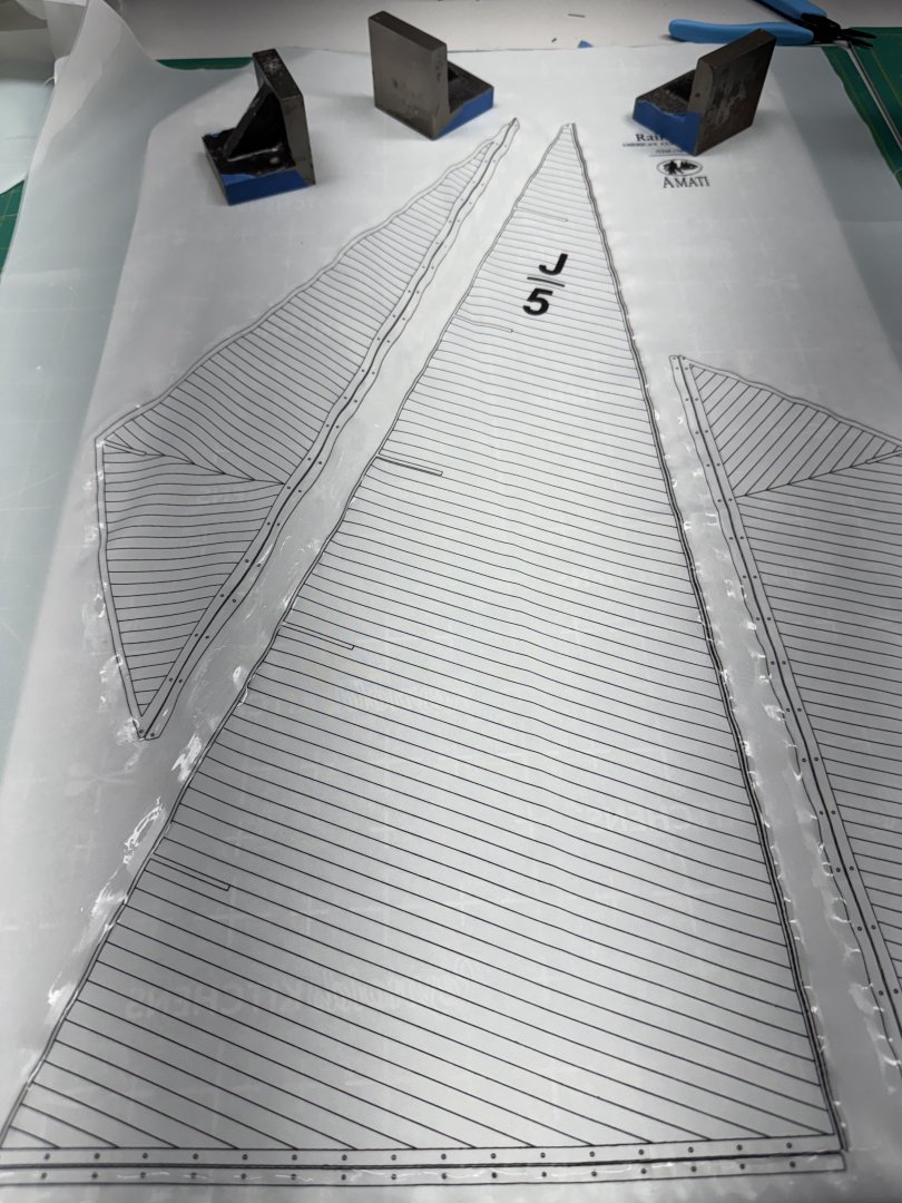
Deck is planked and has two coats of Wipe-on-Poly (water based) applied. Will have to do one or two more. After the first coat the grain in the wood (basswood presumably) was raised up considerably. A good sanding with 320 grit was applied and I am waiting for the second coat to dry to see what the deck looks/feels like. I cleaned up all the Britannia metal cleats and will add them to the boom once the last coat of paint is dry. The mast also has another coat of paint on it and I added the eyebolts to the ends of the spreaders. I am considering painting some of the provided line gray as I am pretty sure these boats had wire rope standing rigging, not hemp. I laid out the sails on a sheet of parchment paper (don't want to glue the sails to the work surface) and added some weights to keep it stretched out (more or less). Then I went over all the edges of the sails with fabric cement. Hopefully the fabric cement will keep the material from unraveling once the sail is cut out. The objective it to get the fabric cement on just the least little bit of the line outlining the sail and very little on the sail material. Easier said than done. The wrinkles shown below will be substantially reduced (I hope) one the fabric cement has dried. Once I get the deck WoP completed I can mask off the deck and take the hull to the spray booth.
-
Quick look through Wikipedia and the 1934 Rainbow hull was made of bronze plates on an iron frame so the cleats were probably something other than wood. I am going to use the provided cleats "as is" after I clean the mold marks off the bottom so they will sit flat on the deck.
-
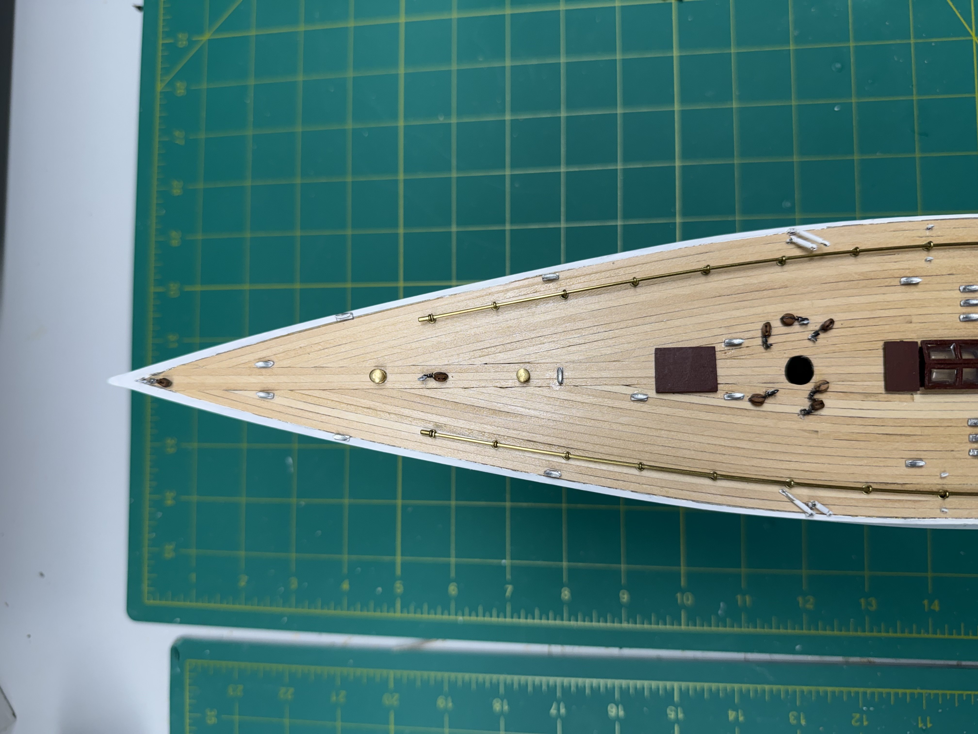
Deck planking is completed. Exactly one full length piece of planking material extra plus half a dozen much shorter pieces. Be careful with the planking, there is not much to spare. No sanding or finish on the deck yet. Plan of a 220 and 320 sanding and at least three coats of Wipe-on-Poly to protect the deck hen my masking prowess proves to be less than satisfactory. The pictures of the finished model at the end of the instructions shows that the area on top of the hull at the bow and stern is painted the same as the hull so the deck needs to be masked off very well as I will have to spray the top of the hull at least at the bow and stern. I also have the second coat of white on the mast. It needs one more. Boom has three coats and just needs some touch up and it is ready . Tamiya primer spray paint arrived today so once the deck finish is applied and masked it will be time to start painting the hull. While the hull is drying between coats I will work on the sails and figuring out what to do about cleats. Syren boxwood ones are still not here. Will at least prime the Britannia metal ones from the kit. Not sure what material was used for them on the real boat. If the hull is aluminum as I seem to remember reading somewhere than I suspect the cleats were also aluminum so maybe leaving them as is would work too.
-
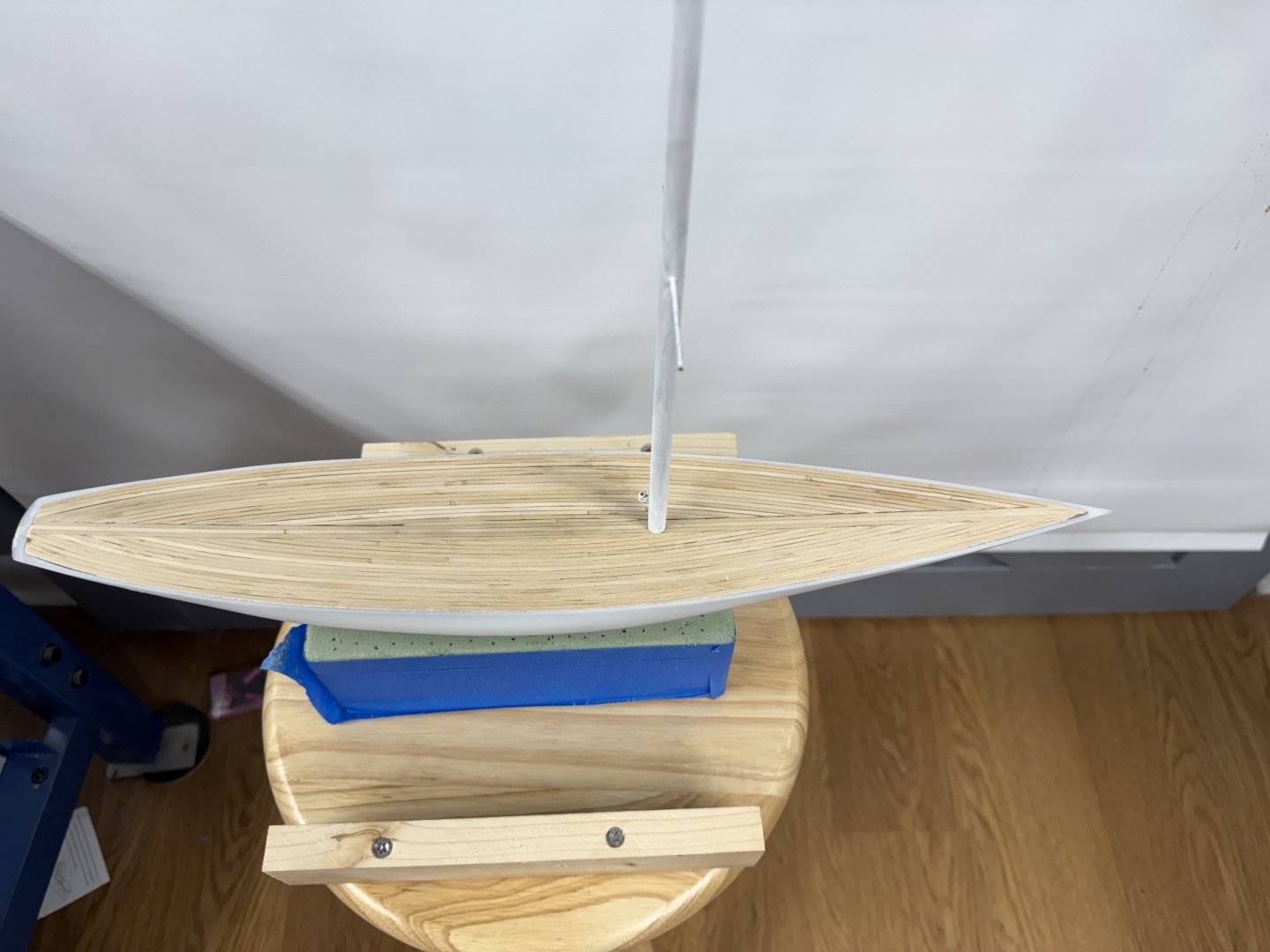
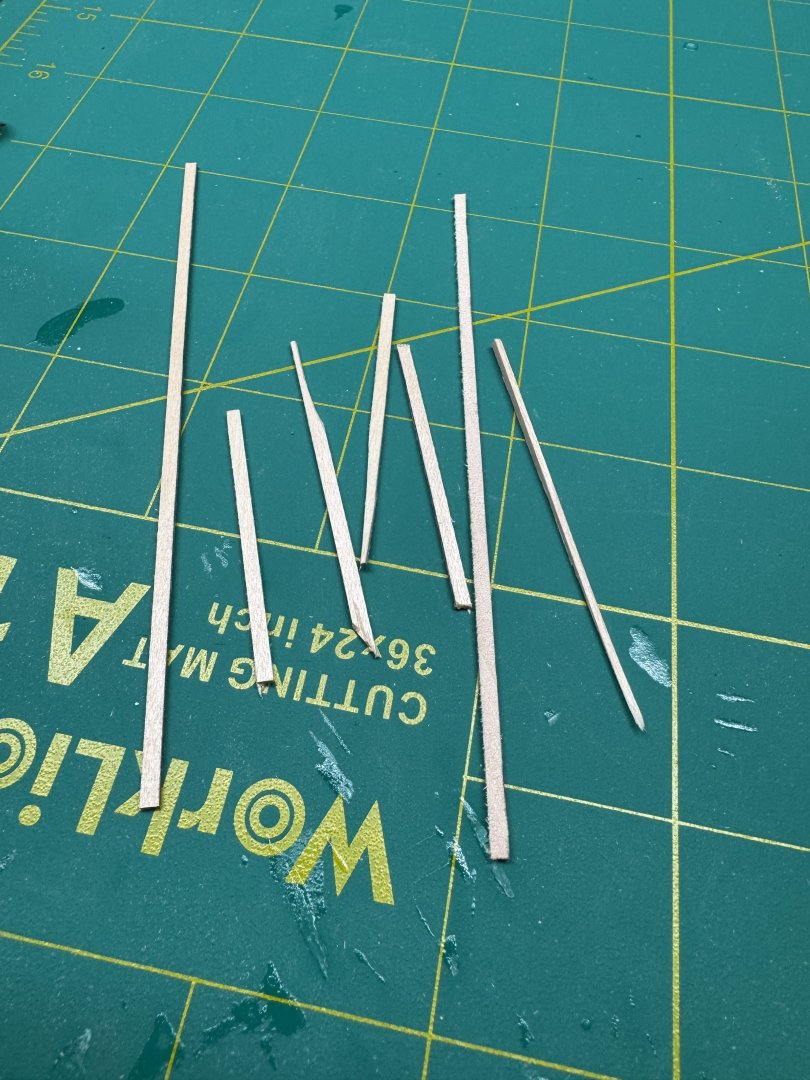
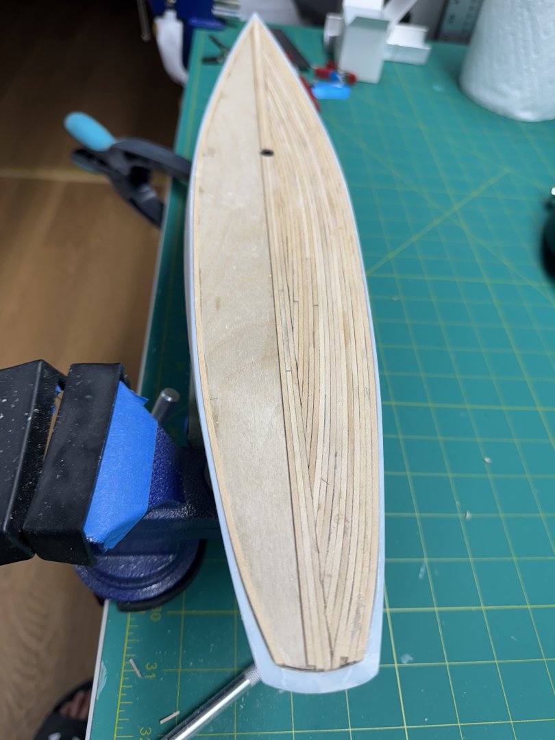
I started planking the deck. As I said above I started with three planks down the centerline then moved to the outboard edge and working inward per the instructions. Before I started the starboard side I divided the planking strips up evenly to see how much "loss" was permitted. I got the starboard side completed but had to resort to cutting planks when it became obvious that there were not enough full length planks to cover the entire deck. No mention of this in the instructions nor in the drawings (there are NO pictures of the model under construction in the instructions only somewhat stylized drawing )showing the planked deck. Here is what I had left over. with the starboard side completed. None of these are over 6" long so you need to be "thrifty" with the planks or you will run out. Here is the starboard side with the deck planked. One potential problem for later is that the deck planks are not flush with the hull sides at the bow and stern. Amidships the top of the hull and deck planks are pretty much at the same level but as you move forward and aft the deck rises above the hull sides. When I sand the deck after all the planking is done i will try and whittle the difference down but I think the will be some deck "sticking up" unless I can figure out a way to add the missing bulwarks. Something to think about while I plank the port side.


-
Thanks Clare - here is the link to my notman build log:
-
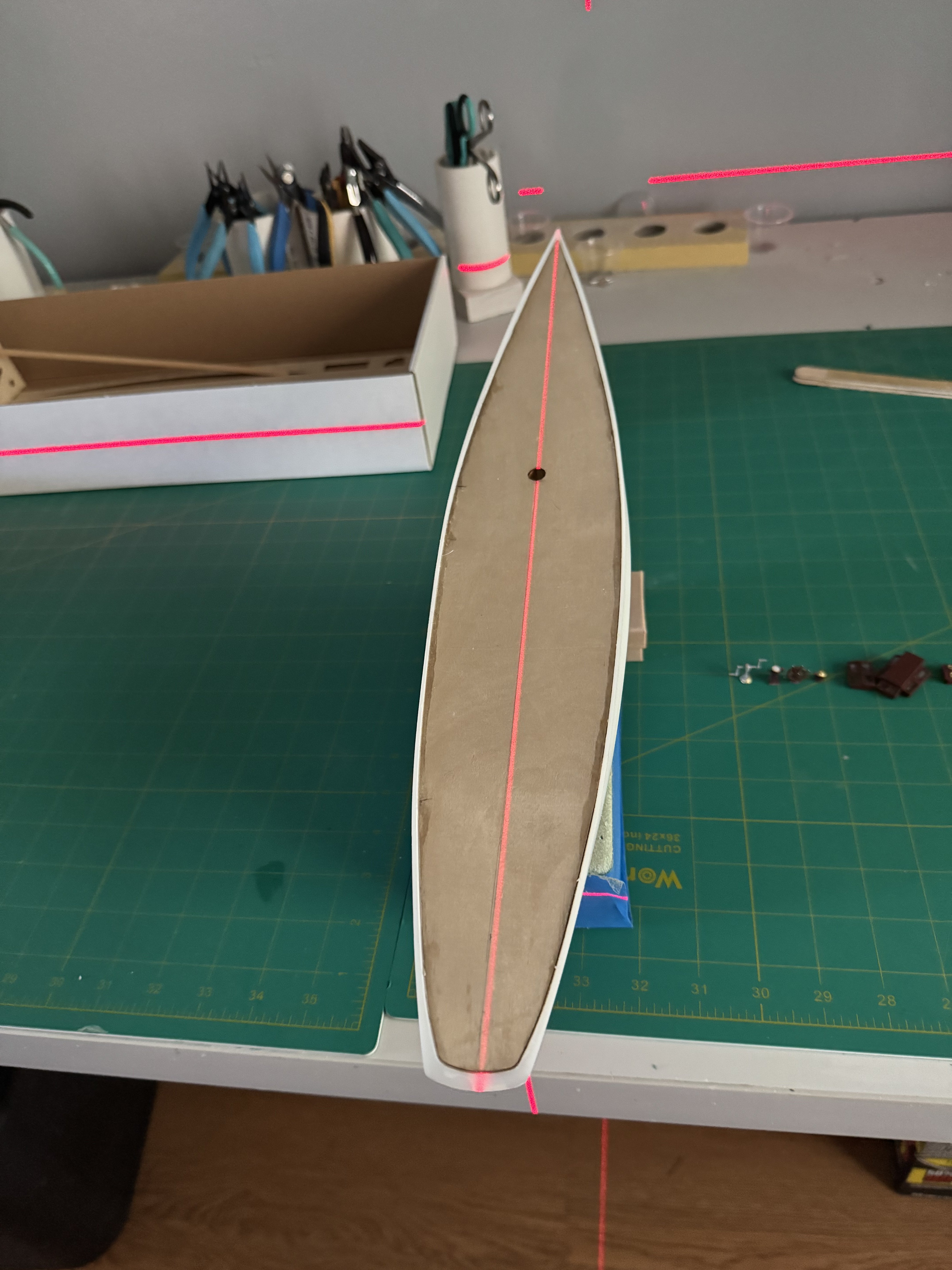
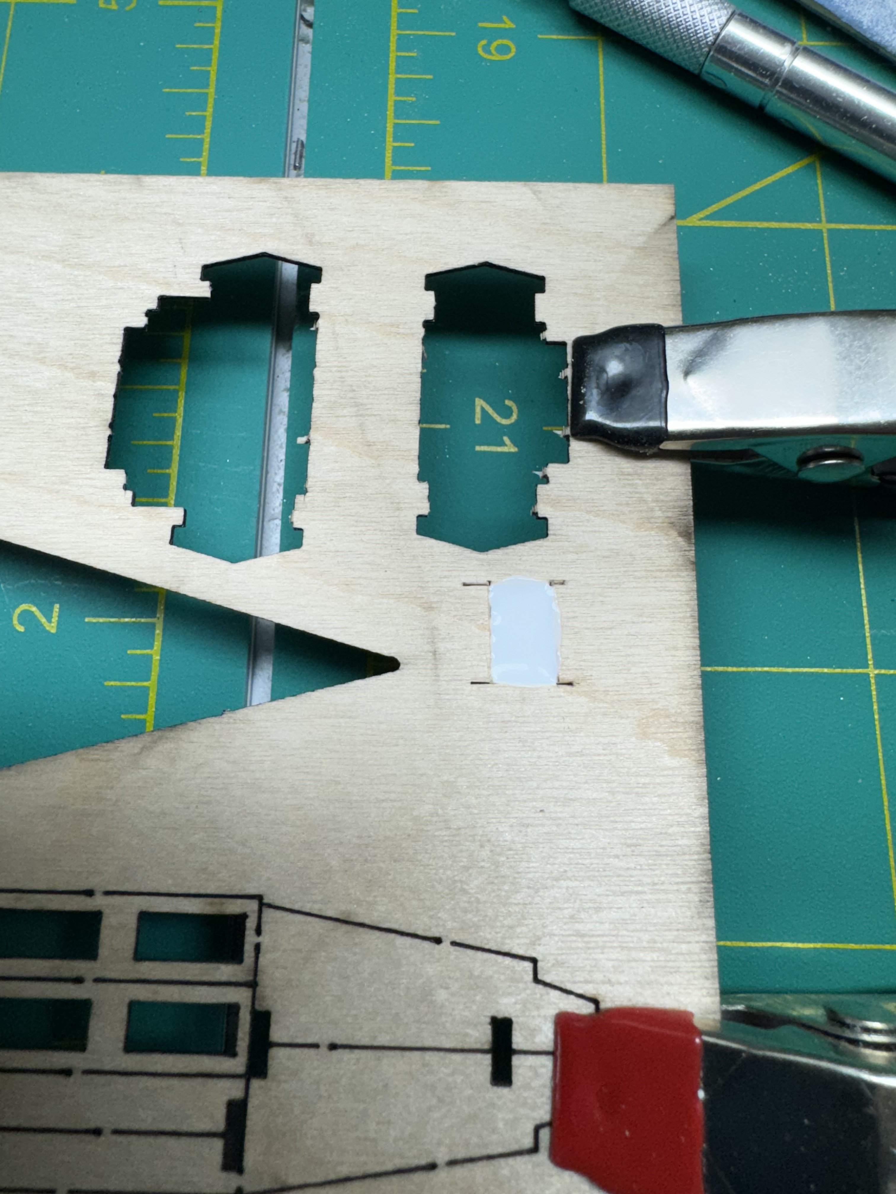
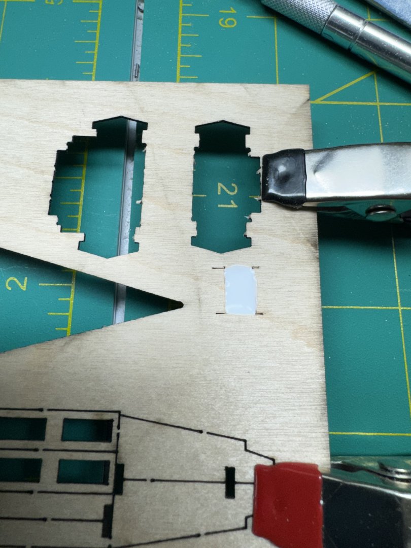
I got the second coat of clear flat on deck furniture and assembled and primed the winch grinder. A note that the nails provided in the kit to link the arms to the center body and become the handles are way, way too thin. I used a piece of .7mm brass rod and that worked more or less perfectly. The window maker has not come completely clear (sort of a fog) in four of the windows but I am hoping it is just taking more time where the material is heaviest. It is difficult (for me) to get a consistent thickness across all the area. I broke out the laser to get a good centerline on the deck as I have decided to plank the deck before painting the hull. My spray primer is still 6 days out according to UPS. My plan is to lay a single plank down the centerline and then add one additional plate on either side before shifting to planking from the edges inward. The instructions say to have two planks down the centerline but I find that somewhat difficult (for me) to accomplish. I find it easier to lay one plank as I find it easier to line it up on centerline rather than just a bit to one side.No mention in the instructions about caulking between the planks but I am going to do it anyway. It probably was not used on the real Rainbow as I believe both the 1934 boats were built of aluminum so the wood decking was just there to provide a better gripping surface than just the aluminum - could be wrong but... I got all the spreaders and eyebolts installed on the mast. Still have to add the eyebolts to the ends of the spreaders but that wil come after I am sure all the spreaders are properly allined. More deck to plank while I adjust the spreaders and paint the boom.


-
I just sent off my pictures of the Charles P> Notman for the NRG photo contest so i can get back to Rainbow.
-
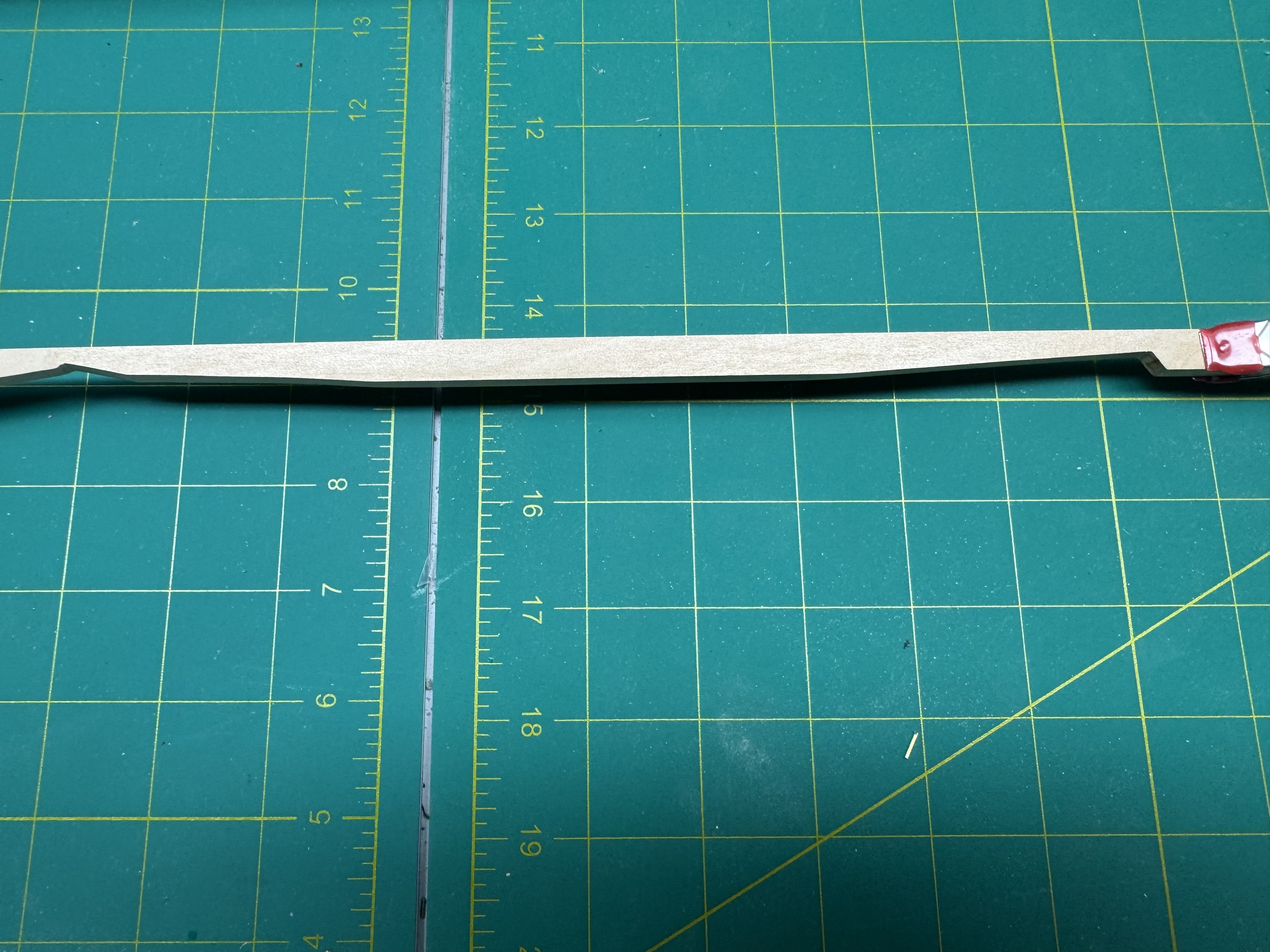
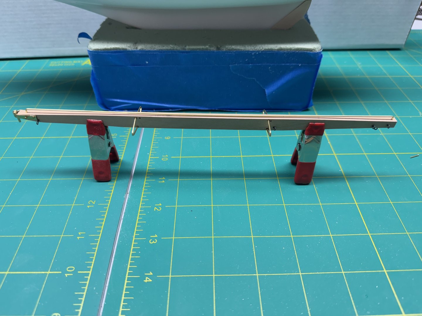
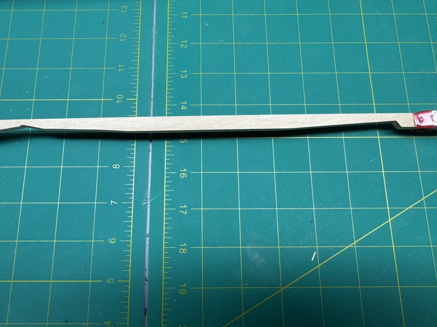
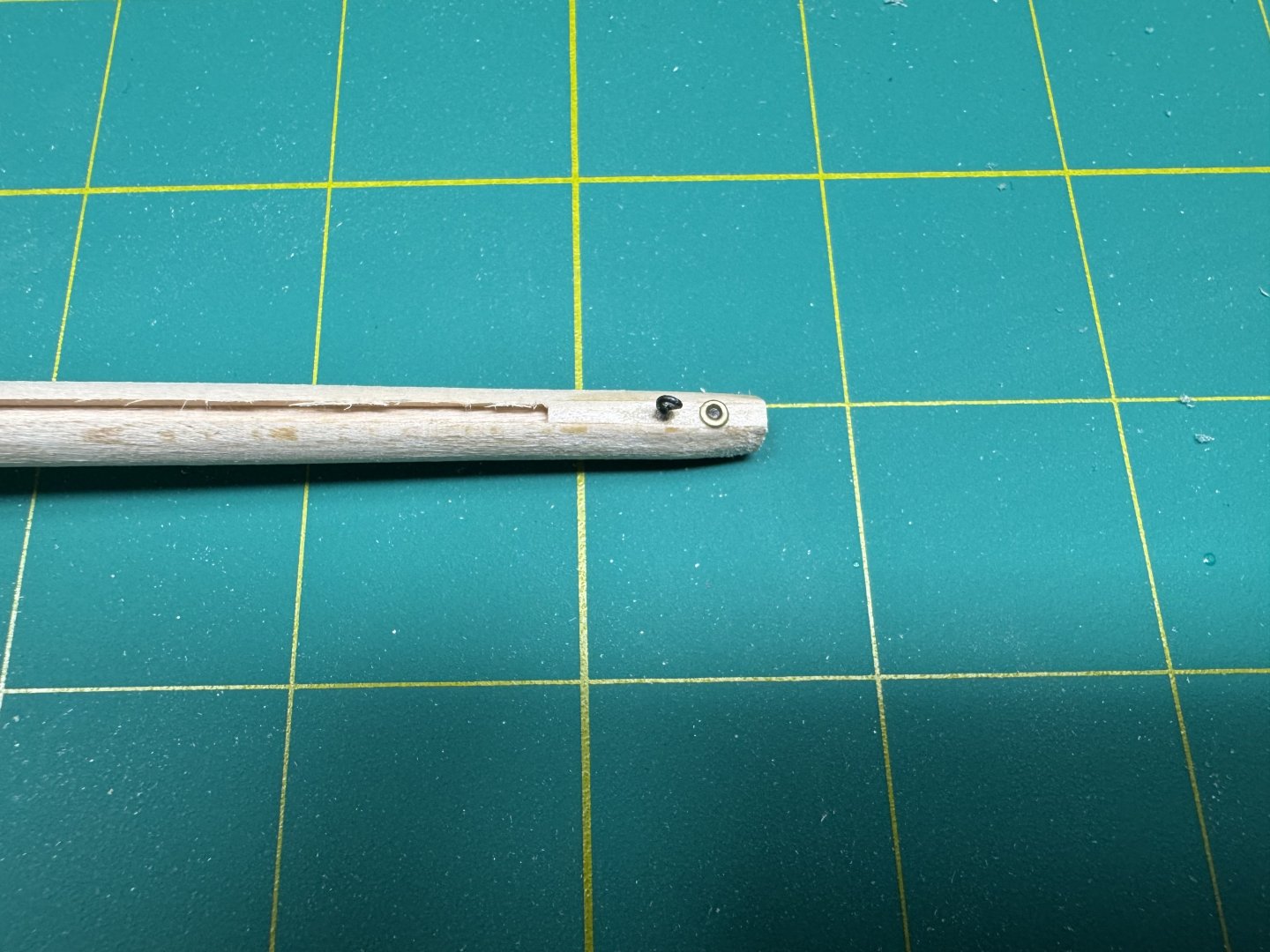
I took out the sails and decided maybe it would be a good idea to hang them up to at least reduce the creases from being folded in the box for who knows how long. Seeing the fuzz at the bottom of the sheet makes me want to use fabric glue along the line when they are cut out. Don't ask me how I know but once the fraying starts it is hard to stop. I finished the boom and its hardware. Instead of the supplied eye bolts I made my own from 24 gauge wire with an .047 "hole" which is close to what would been obtained using the ones supplied. A word of caution for anyone else who builds this - there is one 24" brass rod (1mm) supplied for all the brass needed for the boom. That is not enough to make more than a mistake or two cutting the pieces for the four arms and "arch" (the rod across the top of the boom where the mainsail attaches). Also the nails supplied with the "gooseneck" (where boom attaches to mast) are way too long. I had to cut the nails to less than half the delivered length. I am thinking about putting some primer on the brass as I neglected to clean it before but I had to handle it enough that I doubt a prior cleaning would be good enough. I also got the nav equipment painted and a first coat of clear flat on the deck furniture. I am going to suspend work on Rainbow and shift focus to taking pictures of a previous build for the NRG Photo Contest. I should be back to Rainbow in a day or two.

-
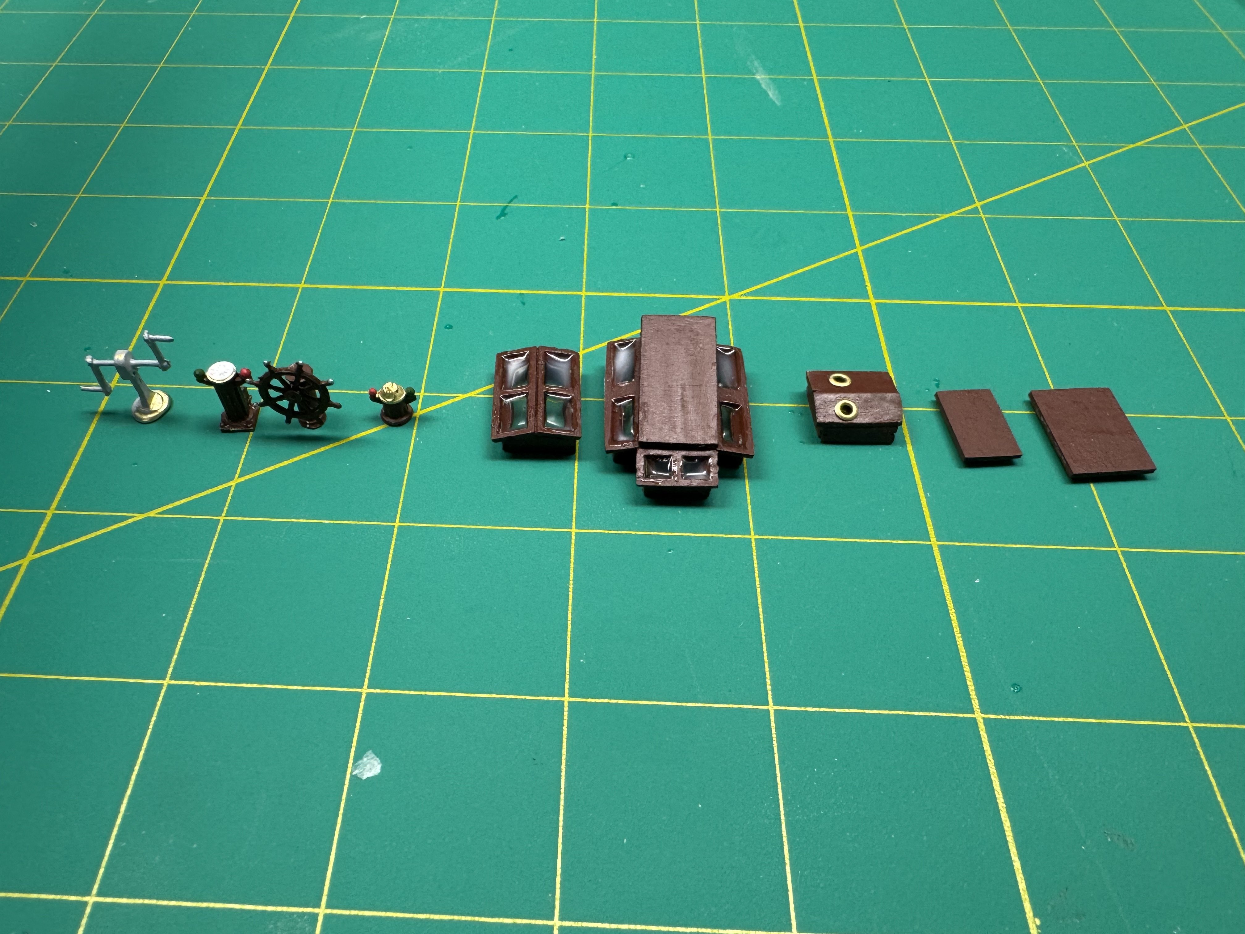
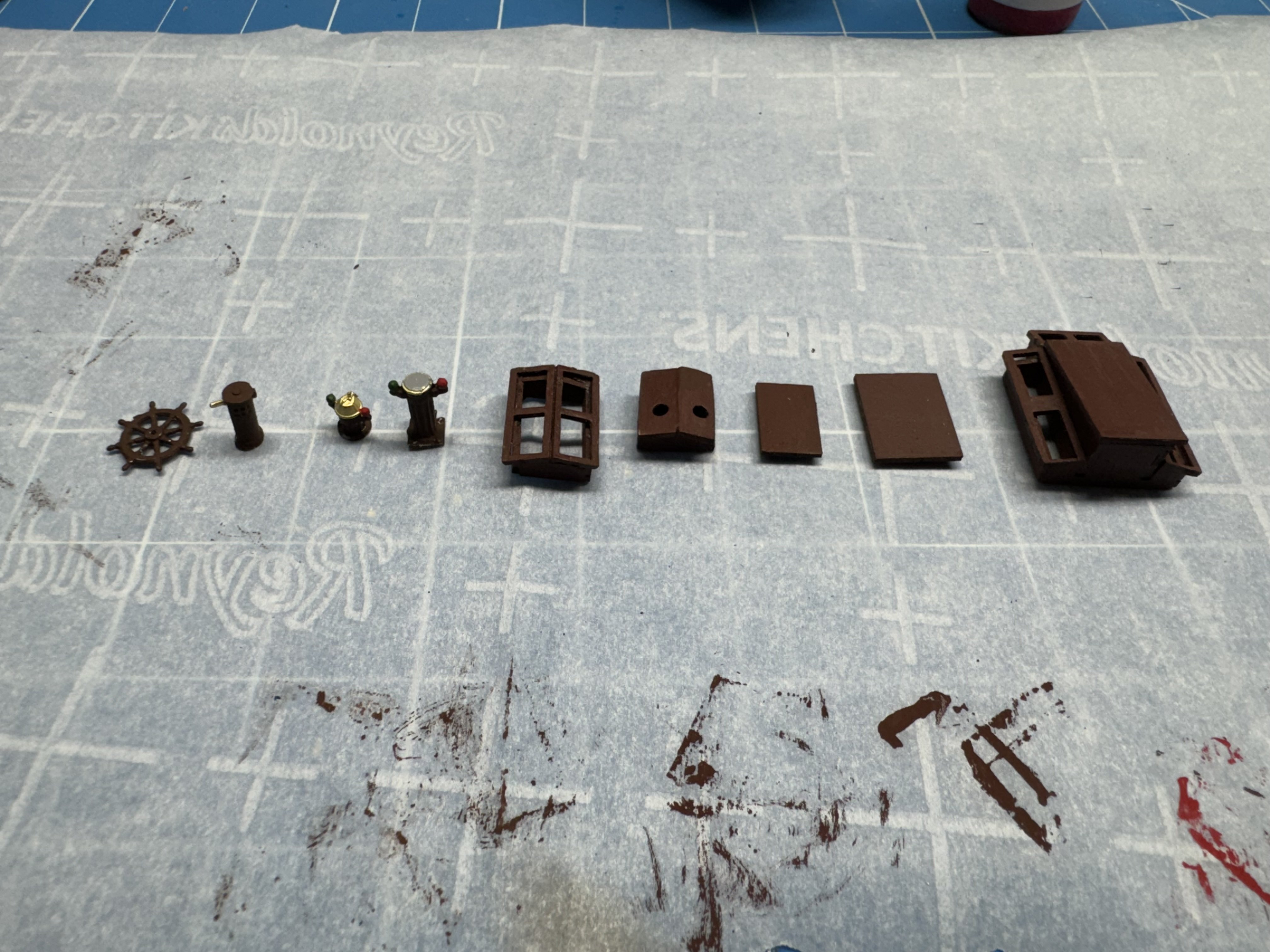
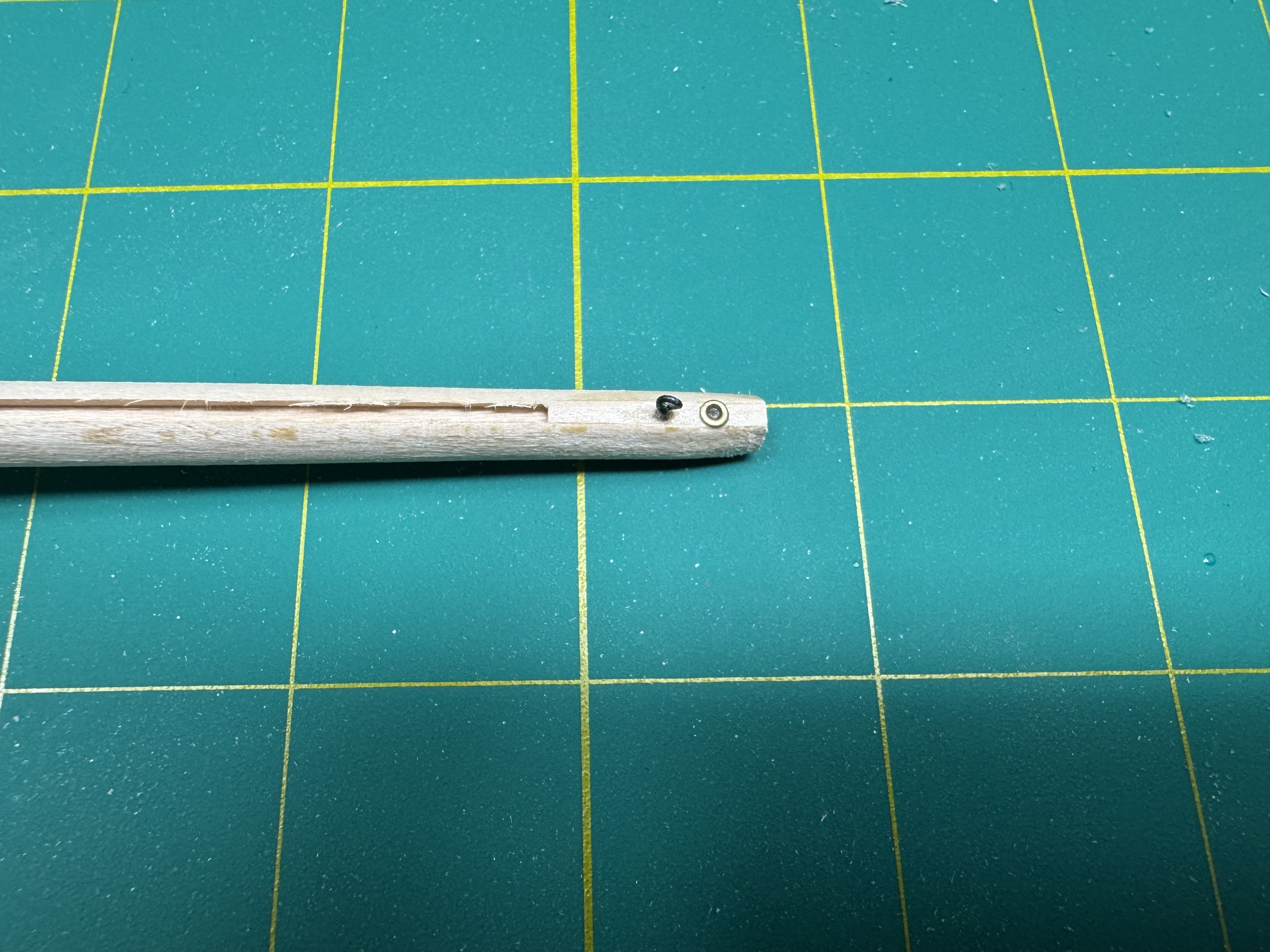
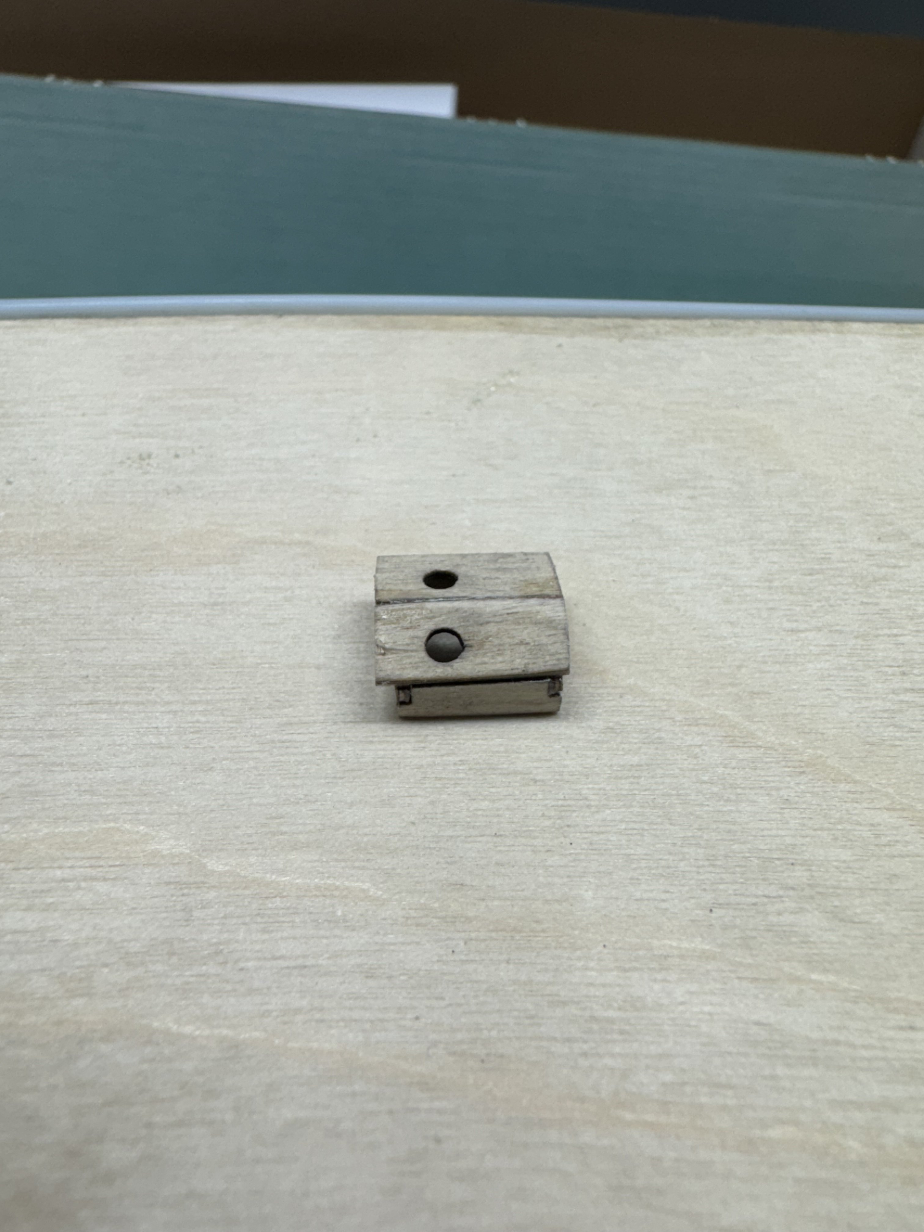
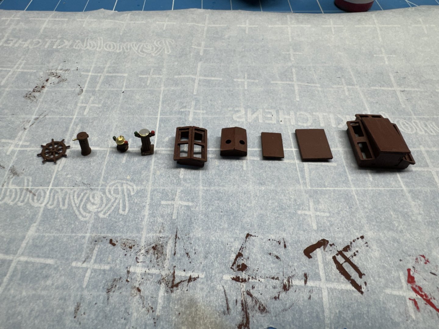
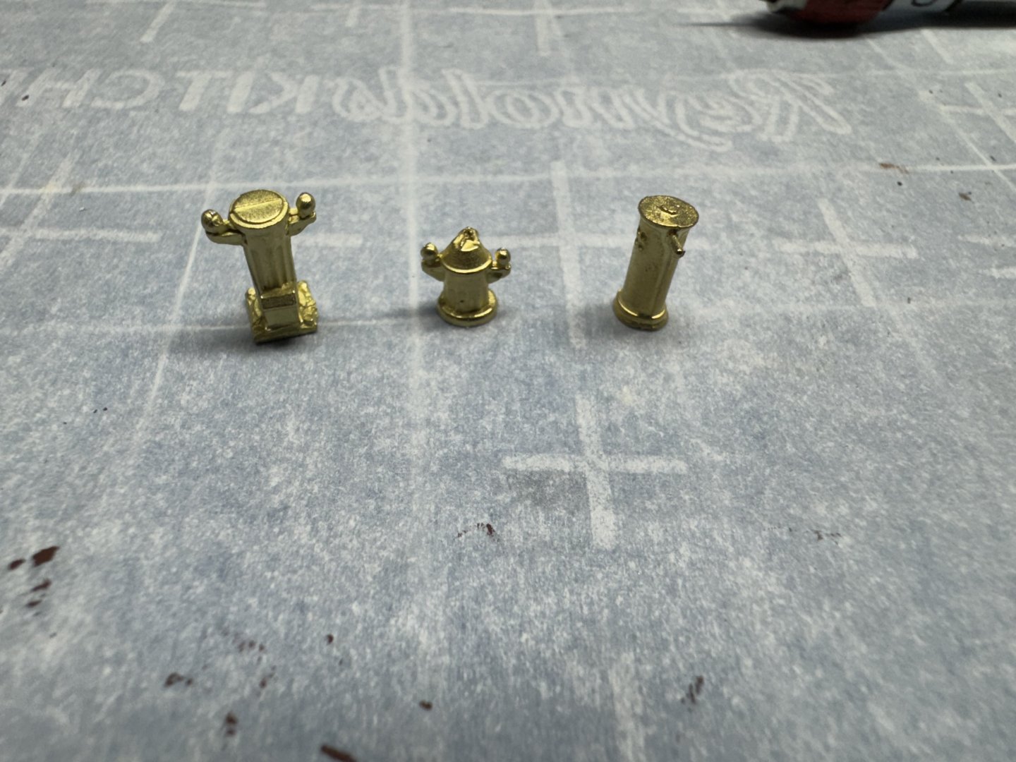
While I let the deck furniture dry overnight before applying the clear coat I started working some of the other items not the hull. I got out the navigation items which are all cast in brass. I had to clean up the areas where the material ran into the mold and the bottoms needed a good deal of filing to get flat. I plan to paint the portions that do not remain brass with a surface primer before trying to add the brown and red/green as I have little faith the the acrylic paint will stick to the brass. As further insurance I have cleaned all three pieces with 99% isopropyl alcohol - another item left to dry overnight I cut the tapers in the boom as shown in the drawing then decided that given all the "things" that get attached to the boom, all of which are painted white I should get the wooden part ready for painting before adding the other "stuff" so I sanded it with 220 paper and then applied a sanding sealer. Will sand again in the morning then start adding the holes and such. The cleats (for the boom and deck) present a quandary. were the cleats on the real rainbow made of metal and thus do not have to be painted? Or were they something else (wood) that would be better represented by some wooden cleats that would be procured (like from Syren where both3.5mm and 5mm cleats in boxwood are available). I will look at my build log for the 1/35 scale Endeavour I built a few years back and see what I did there. I would go look at the model but need a step ladder to see it atop one of the ship model dsplay cases. It is so big it would overpower any room where it sat. Plus since I do not have a case for it (it is almost 5' tall) I do not see the dust building up. Anyway here is the boom with the sanding sealer drying. I have not cut the boom to it final length yet to have easy placxes to hold it. I tapered the mast and added the fittings at the top. I could not get the supplied eye bolt to engage because there is very little room behind the filler piece so i used a home made eye bolt. It is all going to be painted white anyway so all I need is a place to hold the bitter end of the main halyard tackle (the other end gets glued into the opening above the eye bolt). The mast also has a coat of sanding sealer and will be treated the same as the boom getting all the "extras" added on before painting.
-
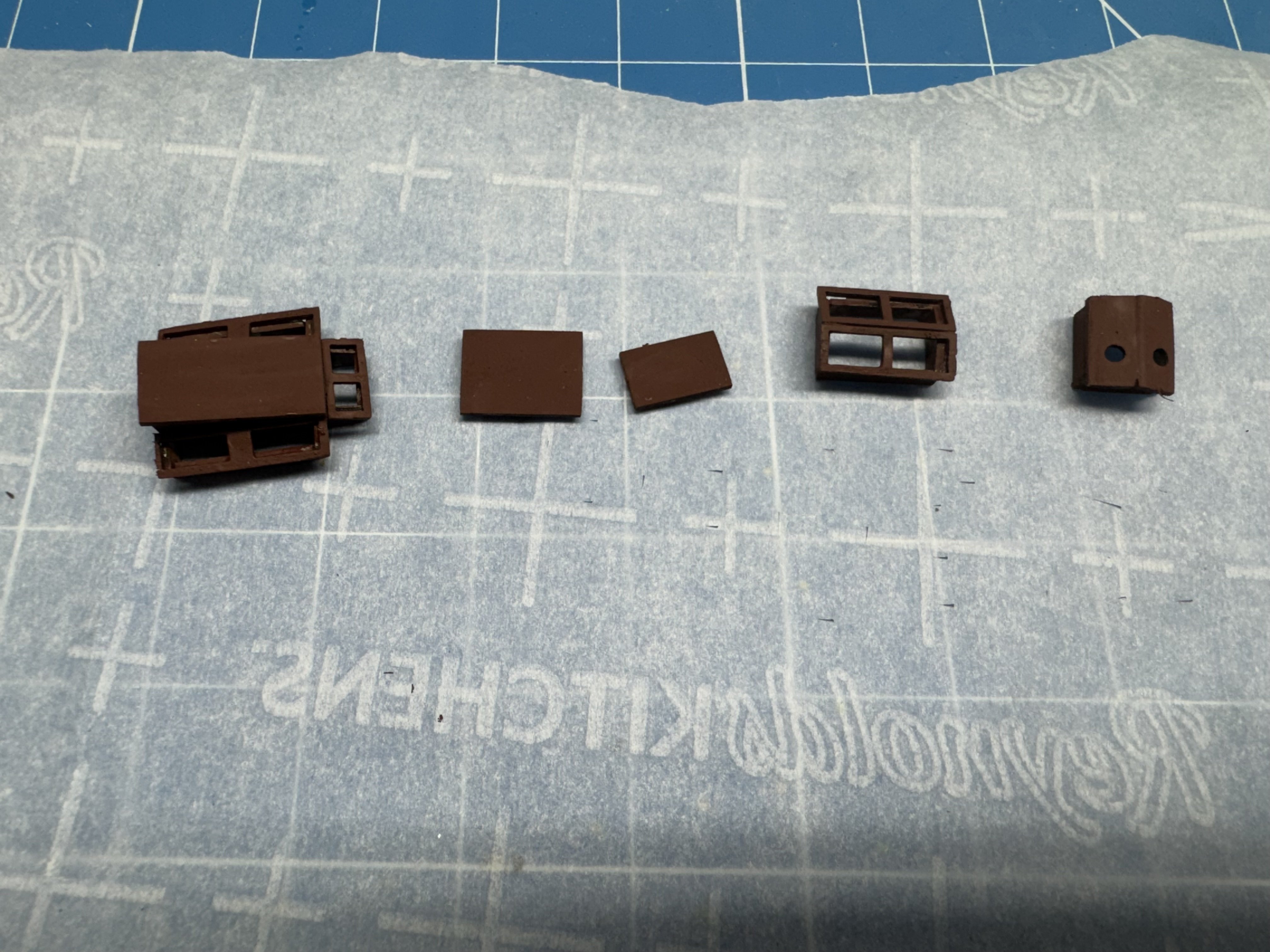
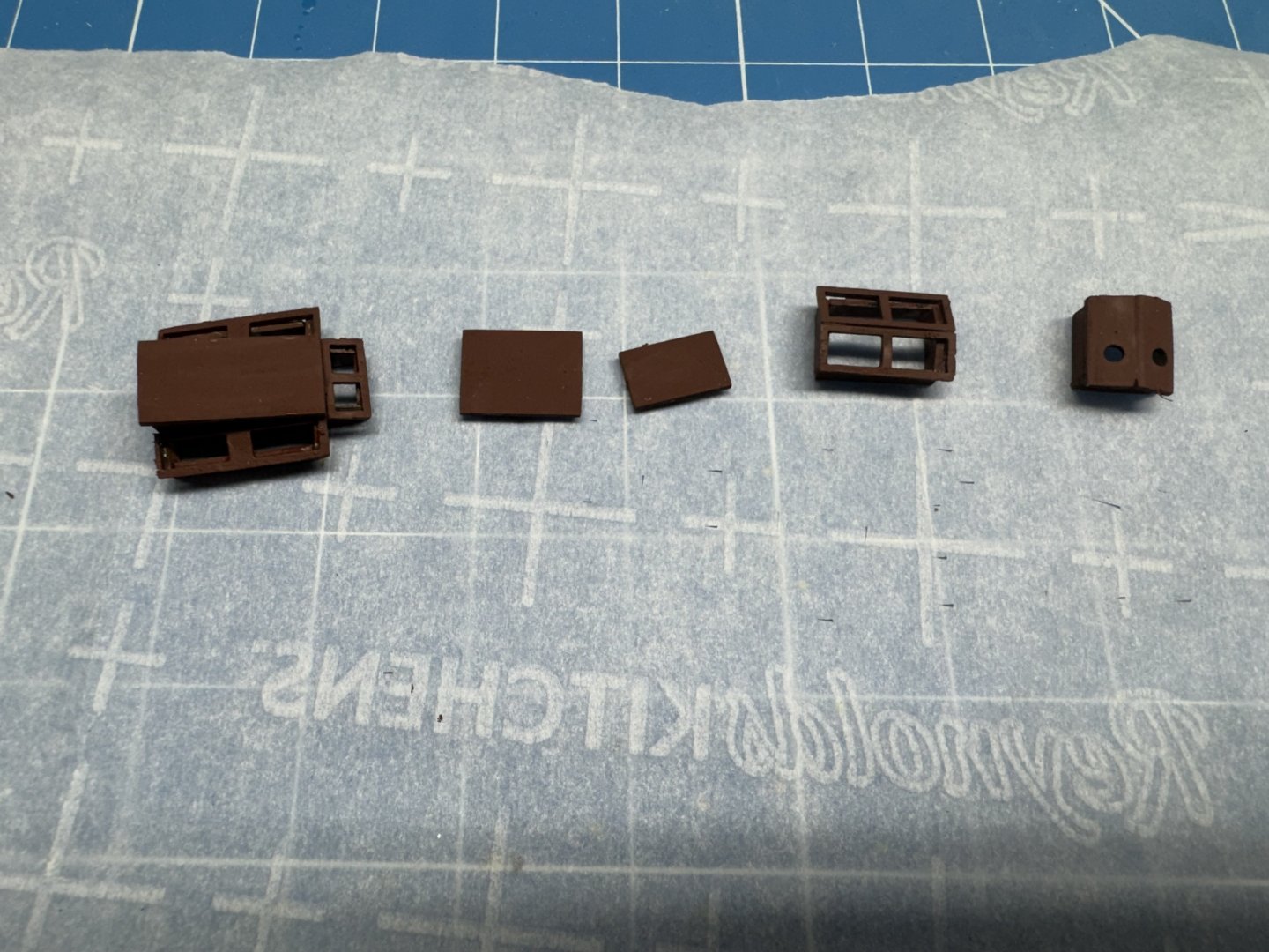
My test run of the window maker was a success (IMHO) So I went ahead and assembled and painted the deck furniture. I added some flat red to the Vallejo flat brown to try and approximate mahogany but it still looks mostly brown to me. Oh well, the deck furniture is not the focus on this model (hopefully). I will wait until the clear coat(s) are on the deck furniture before I "fill in" the windows. No sense making applying the clear coat difficult by having to keep it off the windows. On to the mast and boom while I let the paint dry thoroughly.
-
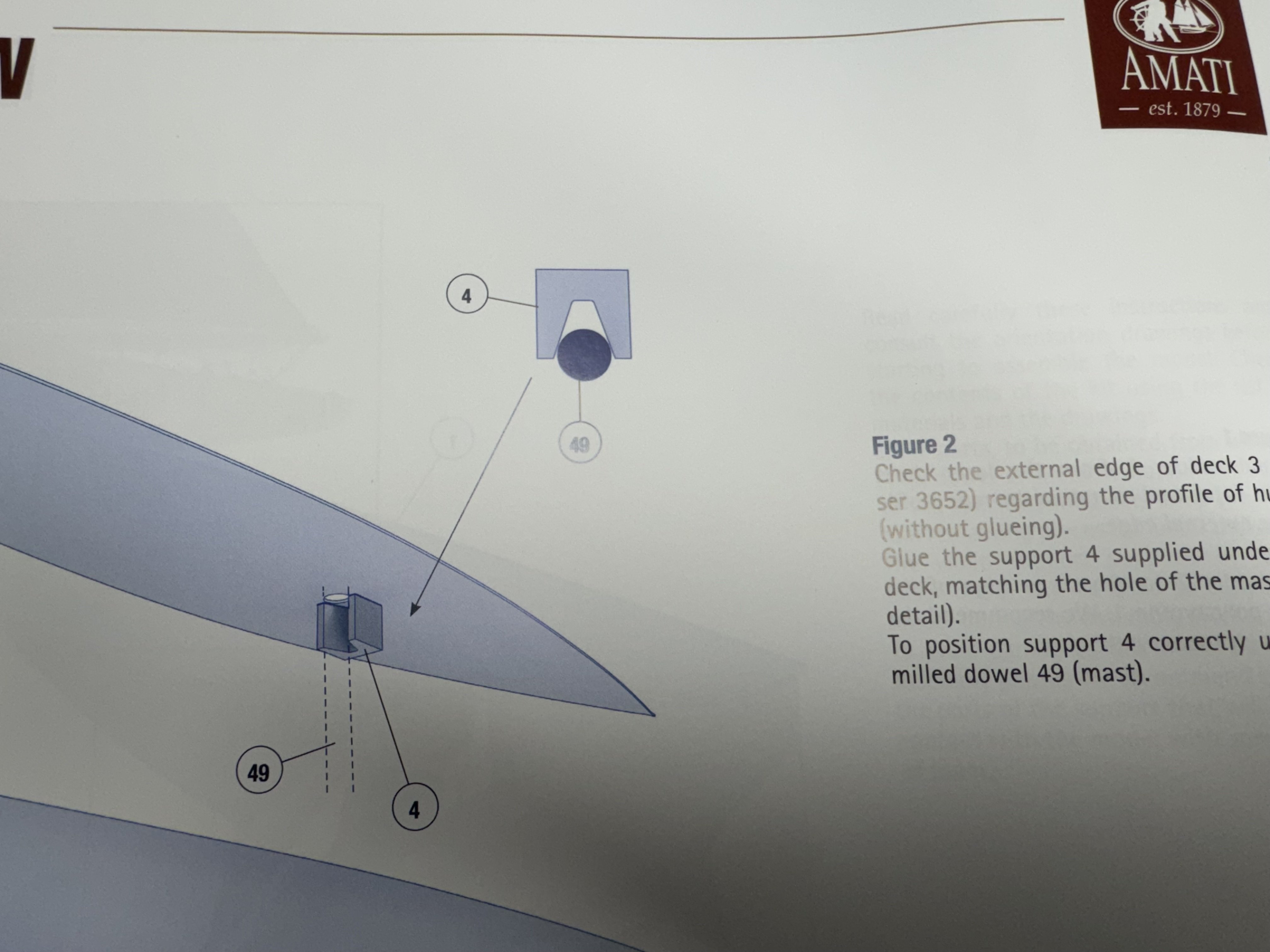
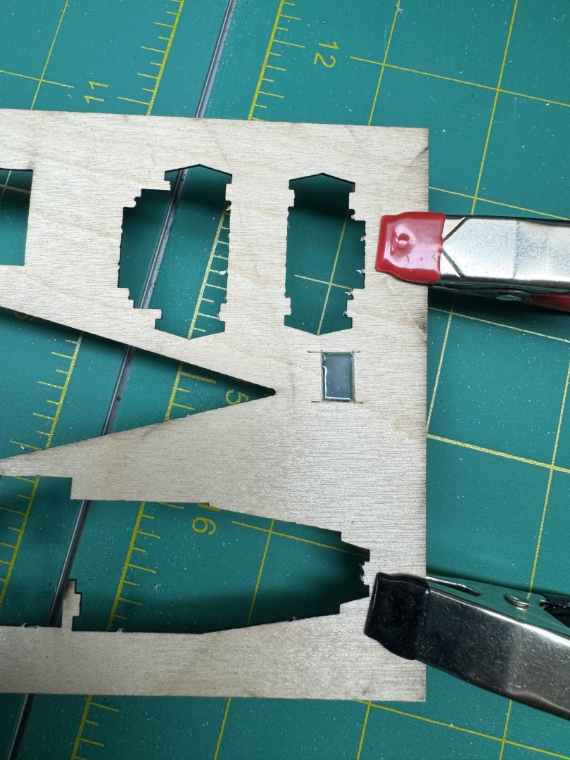
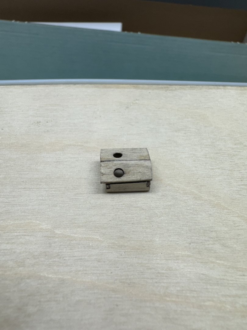
First mistake. I was so focused on getting the deck to fit inside the hull that when I finally got it to fit I immediately glued it in place. I forgot the mast support that is glued to the underside of the decking. After what seemed like gallons (but was actually a few dozen drops) of de-bonder I got the deck up without major damage, installed the mast support and got the deck glued back down. Whew! Another bullet mostly dodged. I am waiting for delivery of the recommended Tamiya primer spray paint so I moved on to the deck furniture. These are really small pieces and getting them assembled and evenly spaced is quite a challenge (for me). I used my magnetic furniture building board to help but still after the rectangular base is together getting the top pieces on and evenly spaced in both dimensions took more than a couple of tries. I had to build on top on the spacer so the clamp would reach the top of the side piece. I am generally not a fan of acrylic windows, especially when they are provided as a single piece and you have to cut the pieces out yourself which is the case here. I have used two different "window maker" products and while they never make a completely clear window they do make a reasonable approximation especially if there is really nothing to see on the other side which is the case here. To see what they might do with the windows here I cut out a "window" of approximately the same size as are on the deck furniture and used Micro Krystal Klear to "fill it in". It will be a few more hours before I can see what it will look like but based on past experience I think this is the way I will go.

-
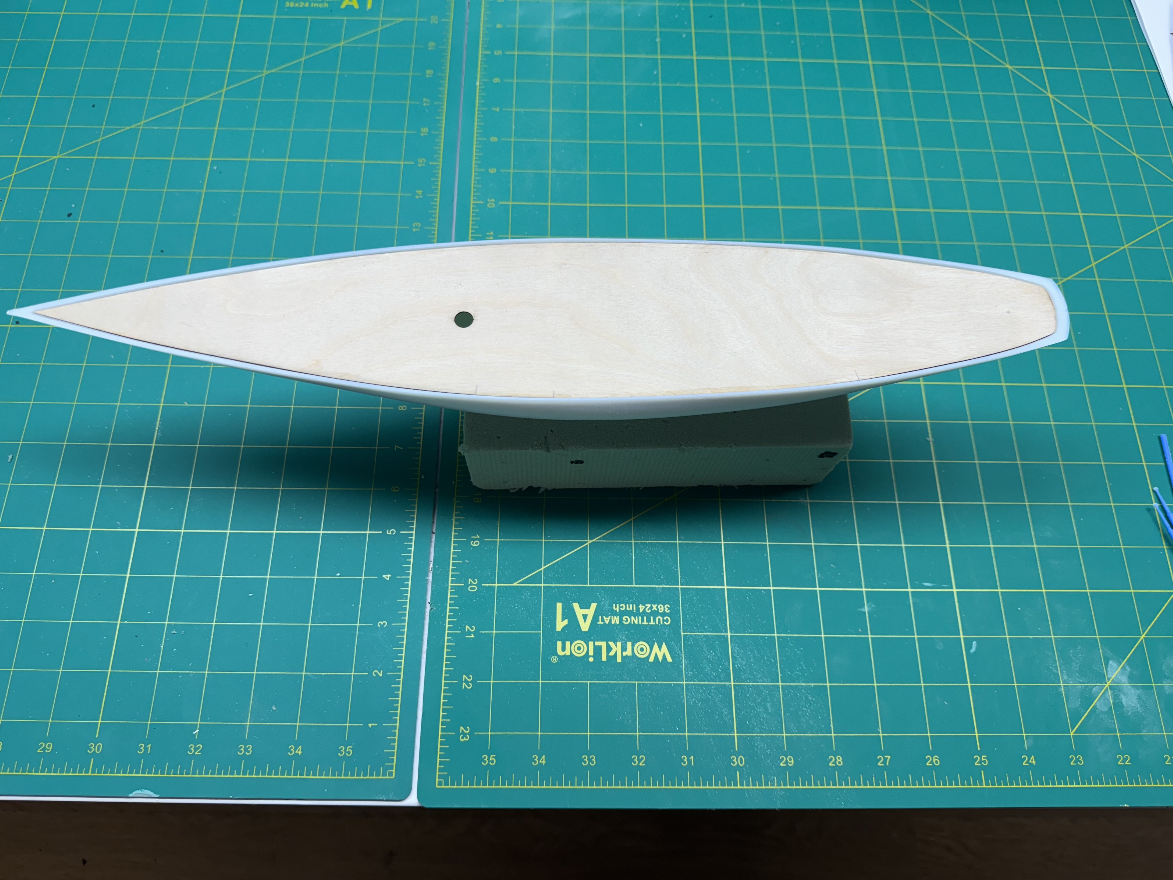
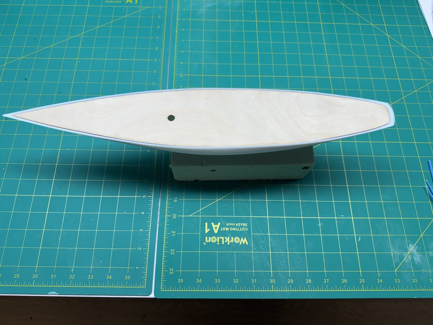
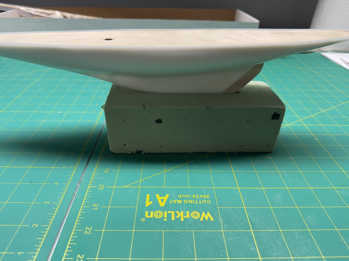
I started gluing the deck down at the bow using medium CA since I knew it wanted to raise up there. After a few minutes I snapped the rest of the decking into the hull and ran thin CA around the rest of the hull. It should soak into the wood and bond (more or less) with the plastic hull. I have not had great success with CA and plastic in the past but there is not a great deal of stress at the joint and hopefully the deck will stay in place. I also found a way to hold the hull - I stole a floral arrangement block from the flower arranger in the house and cut a slot in the top to accommodate the keel. It works for now and I think is gentle enough on the hull paint as it may be useful throughout the build - if I can put up with the green "fuzz" that seems to pour of fthe block whenever I touch it. Maybe I should paint the sides that are not touching the hull.
-
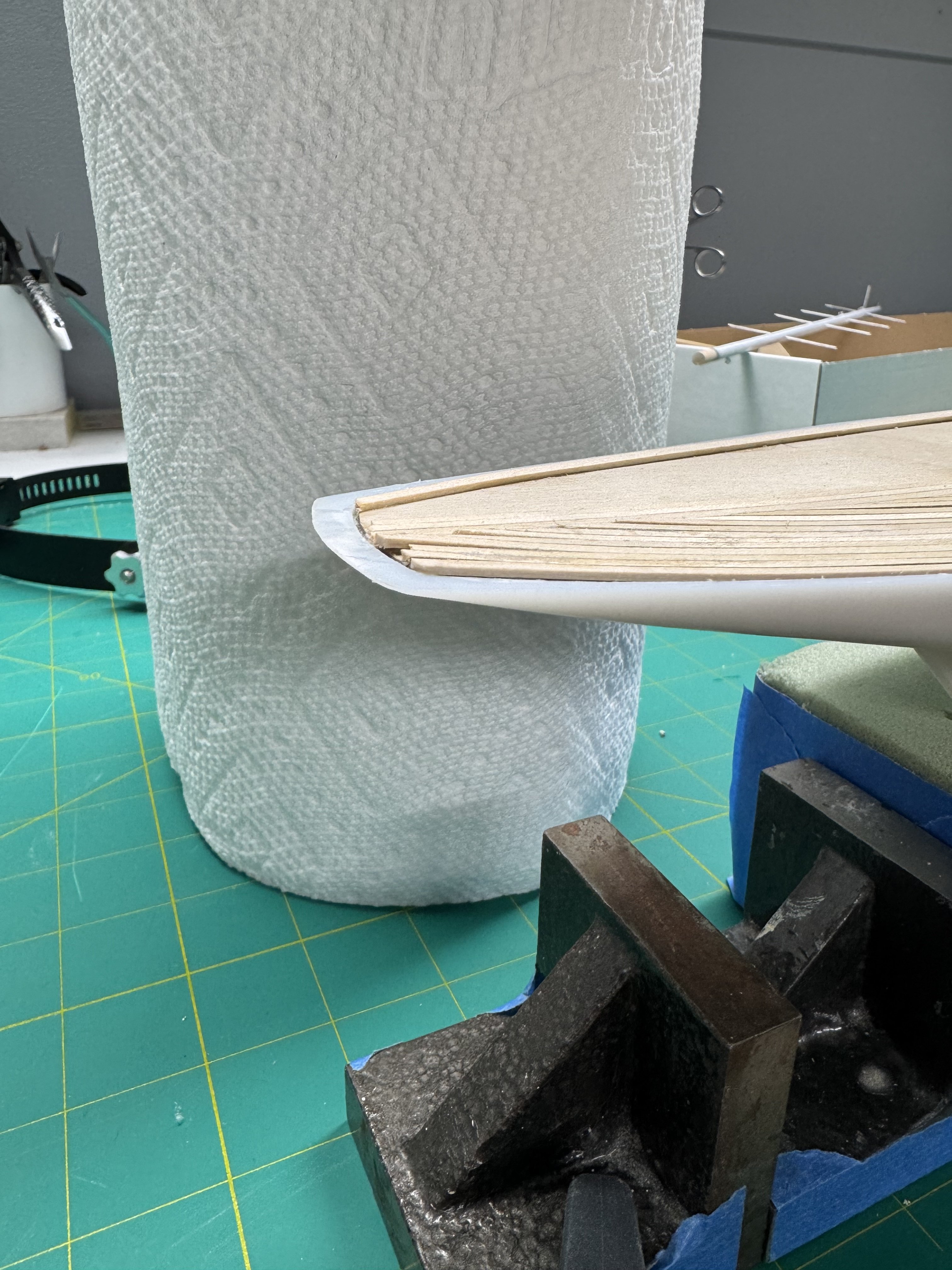
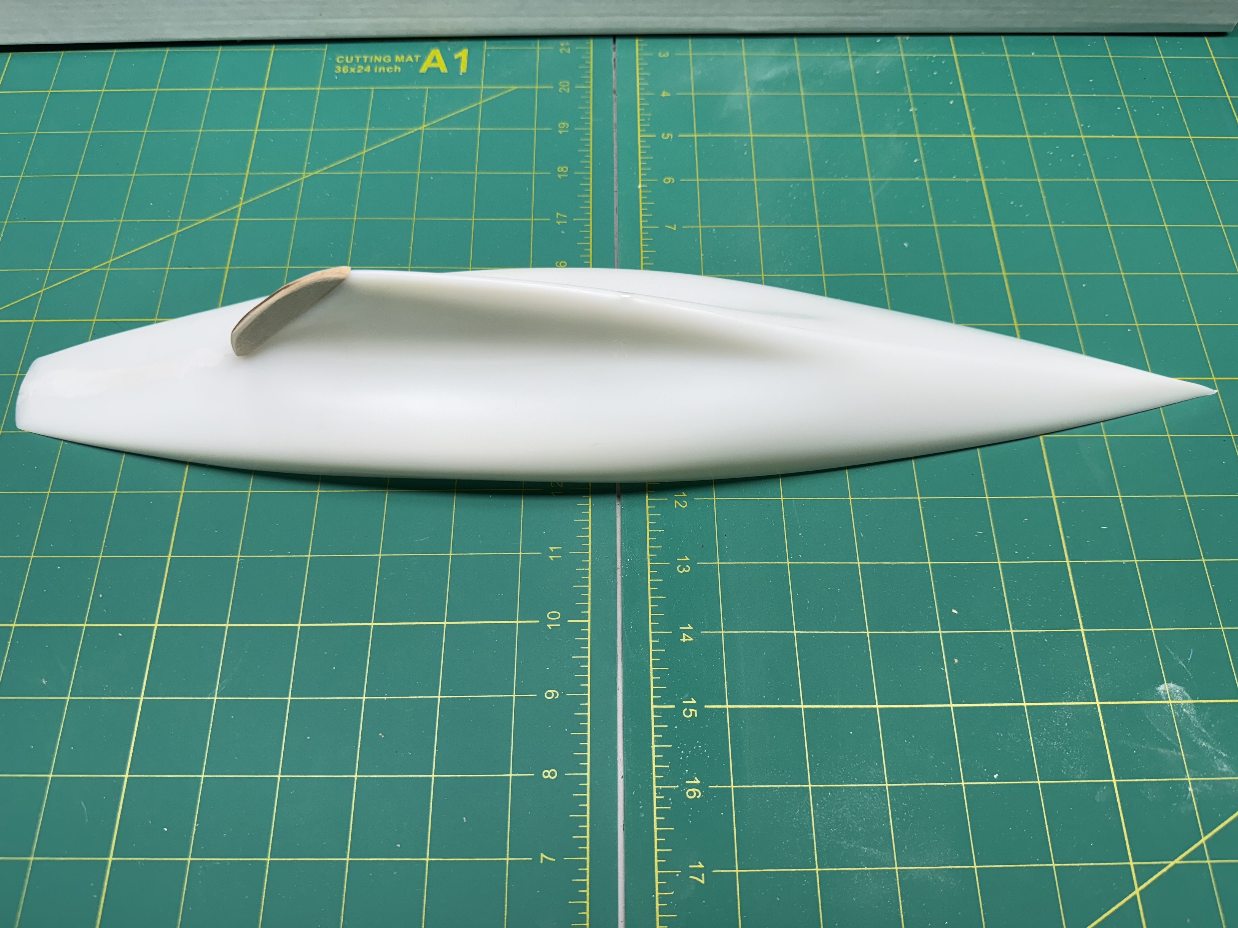
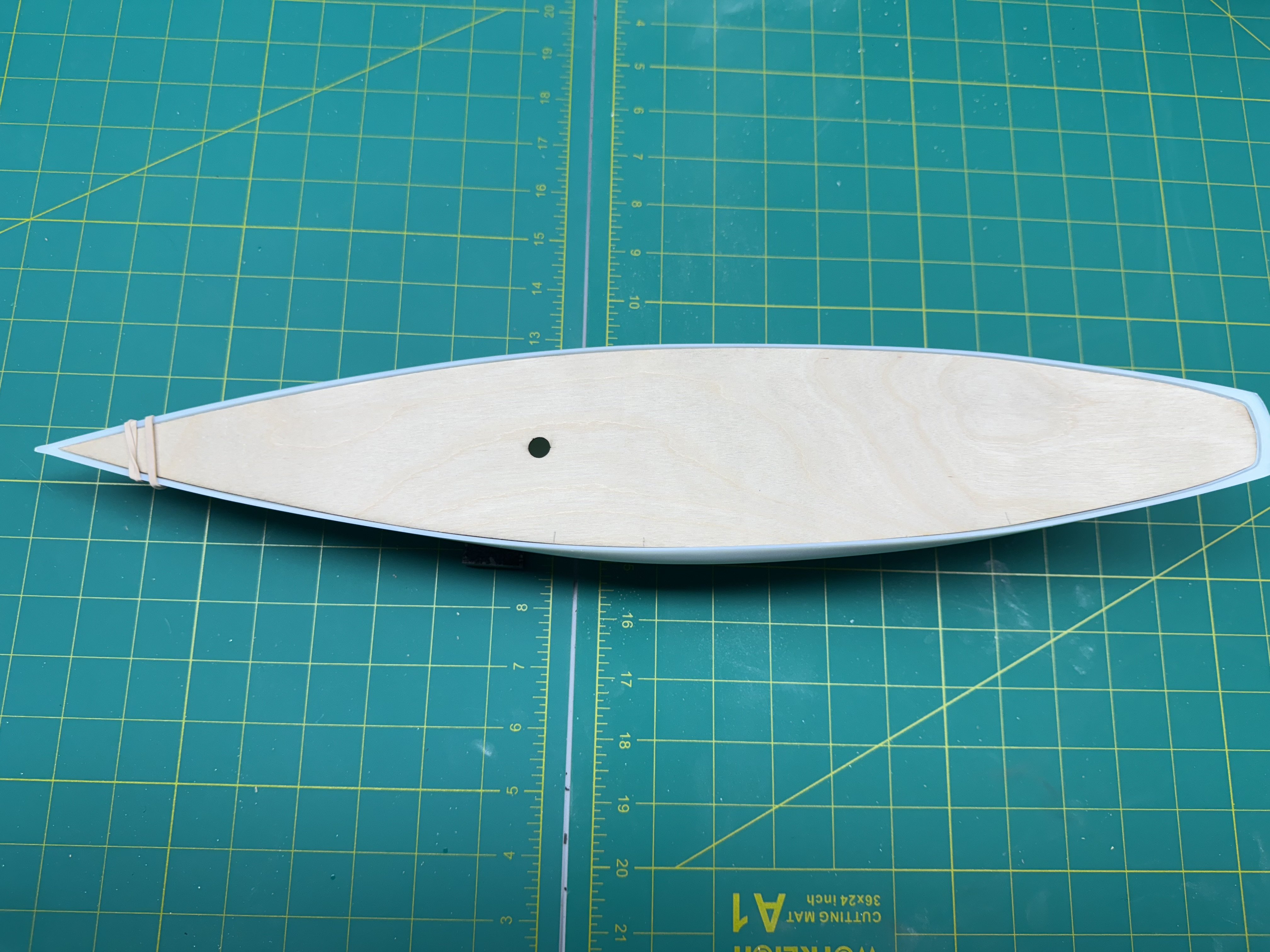
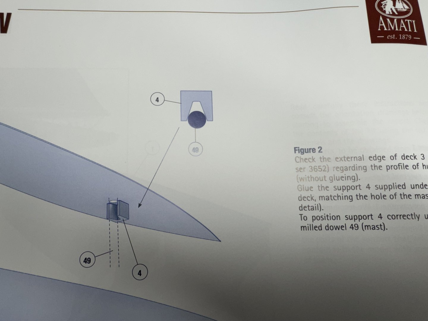
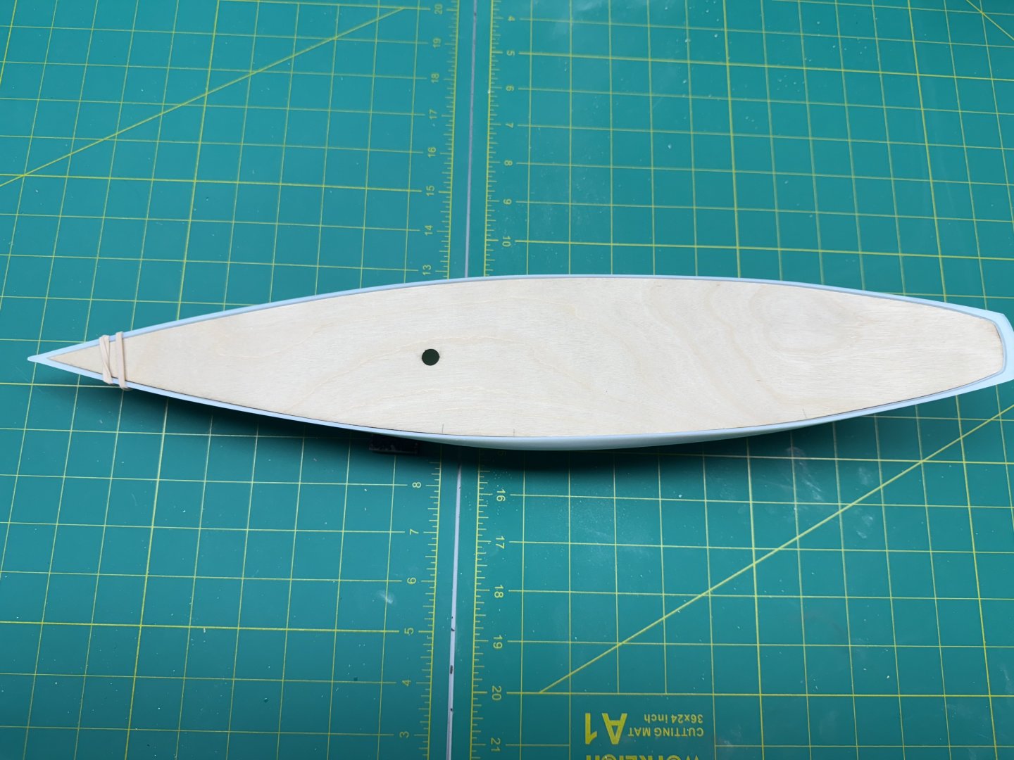
I am building the latest version of Amati's Rainbow (winner of he 1934 America's Cup Challenge) kit - the one with the plastic hull. I also have the same version of the Endeavour (and I am hard pressed to see any difference in the hull but...). The first step is to lightly sand off the mold marks on the hull centerline and taper and add the rudder (which is made of wood - dah). Step 2 is to glue in the "false deck" (which will be planked shortly. It took a bit of fiddling to get the laser cut false deck to fit inside the plastic hull. I would get it seated about 3/4 of the way around, mark where it was too large sand that area, rinse and repeat. You can see some of the pencil marks showing the areas being sanded. Here is the deck dry fit. It apparently has a bit of "warp" as the bow will not sit down without some gentle pressure (rubber bands). The instructions say to glue the deck in with CA and then plank it with the provided planking material. I am not sure why I would plank the deck before painting the hull as that seems to be asking for trouble. Perhaps it is to minimize handling the hull after it painted but I think I will paint it first then plank. I also need to find a way to hold the hull as none of my availble jigs will fit a hull this shape.

-
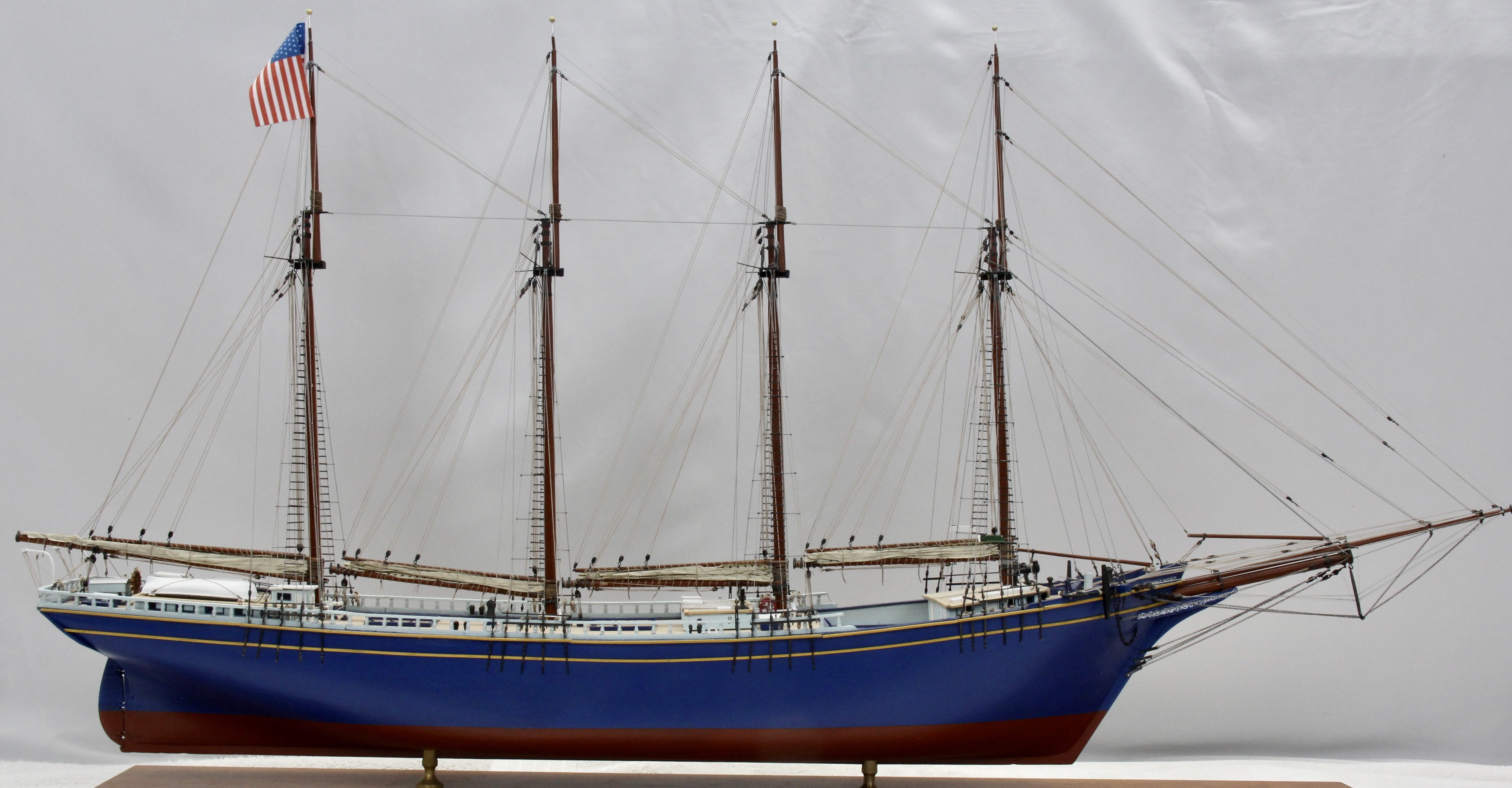
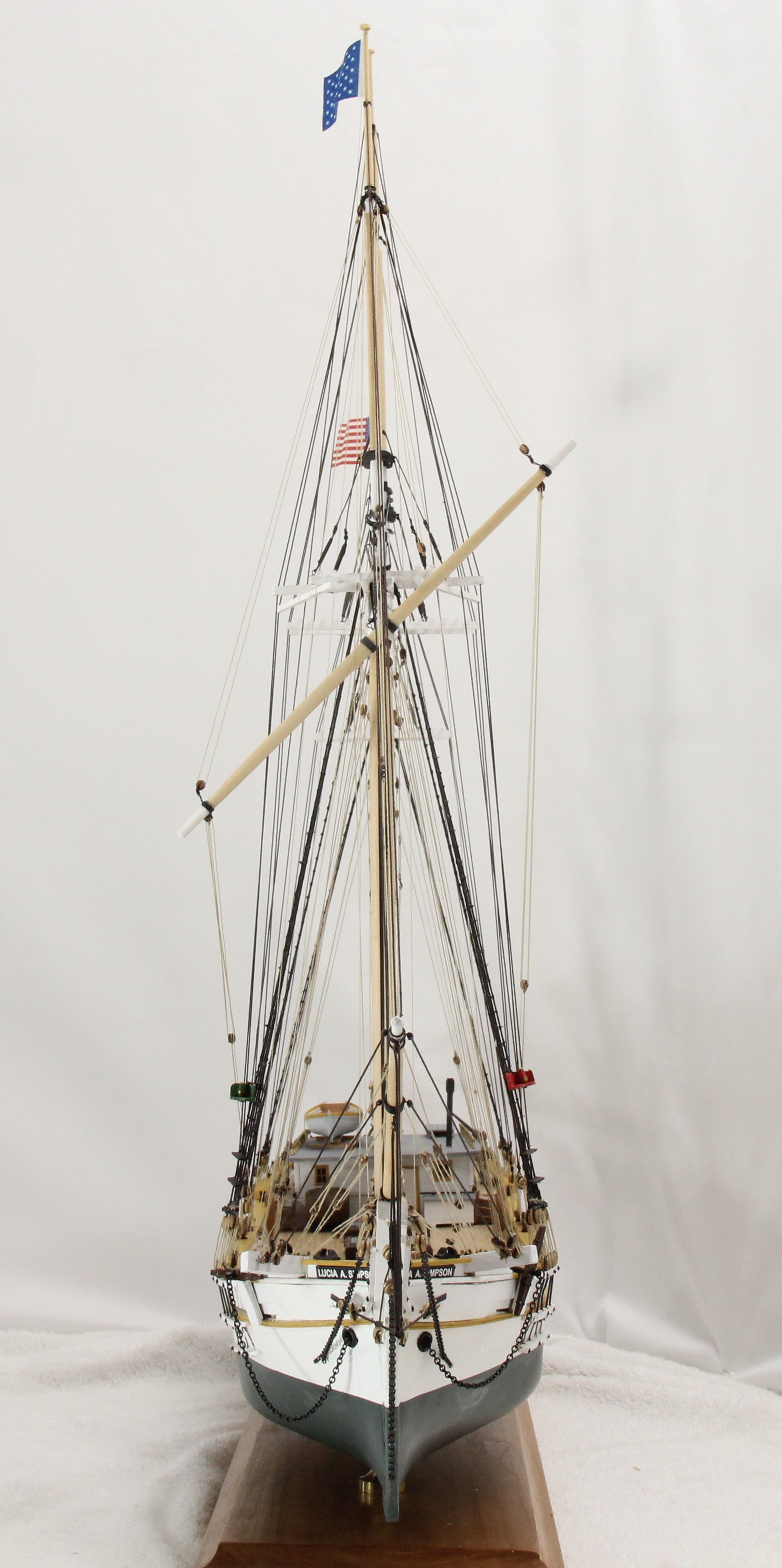
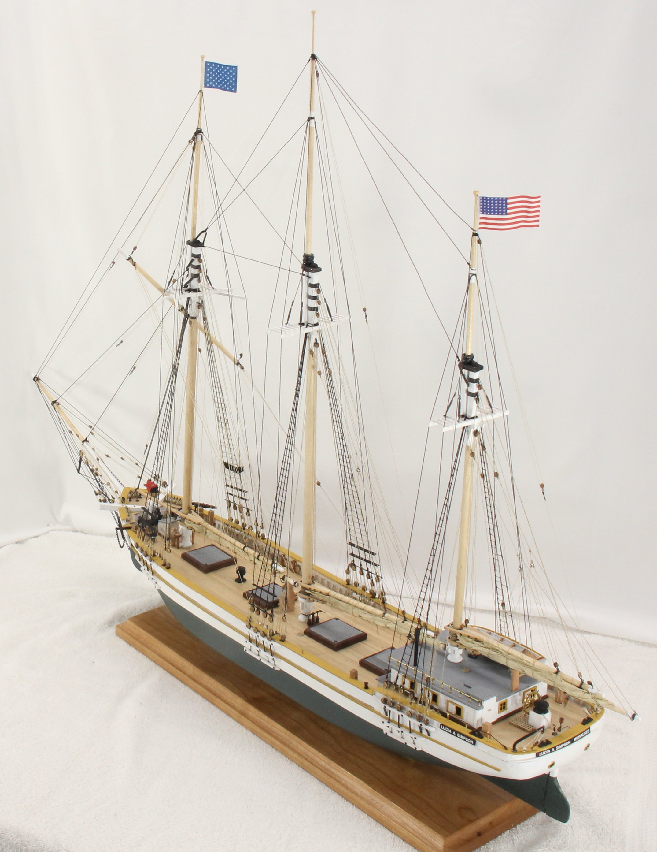
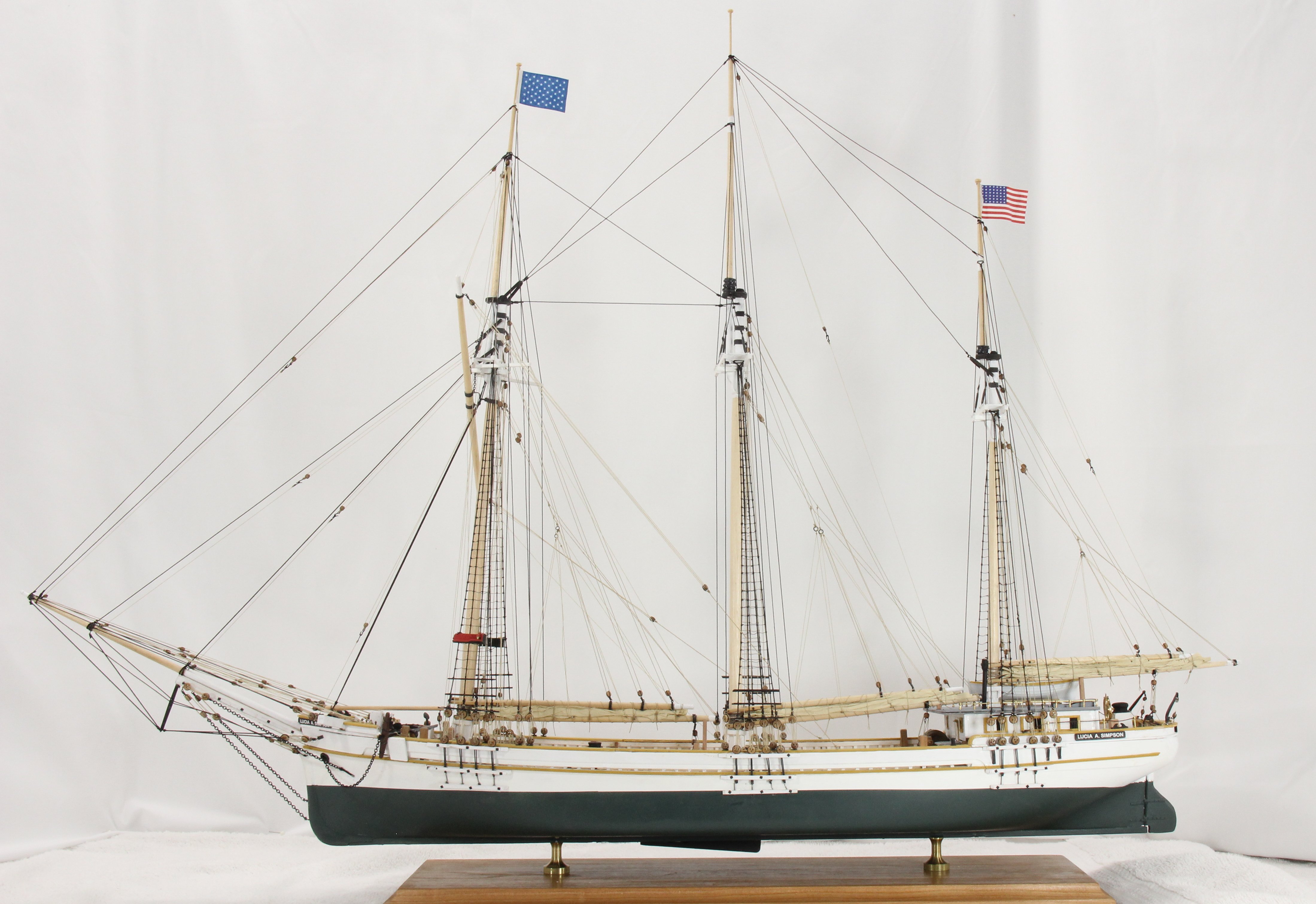
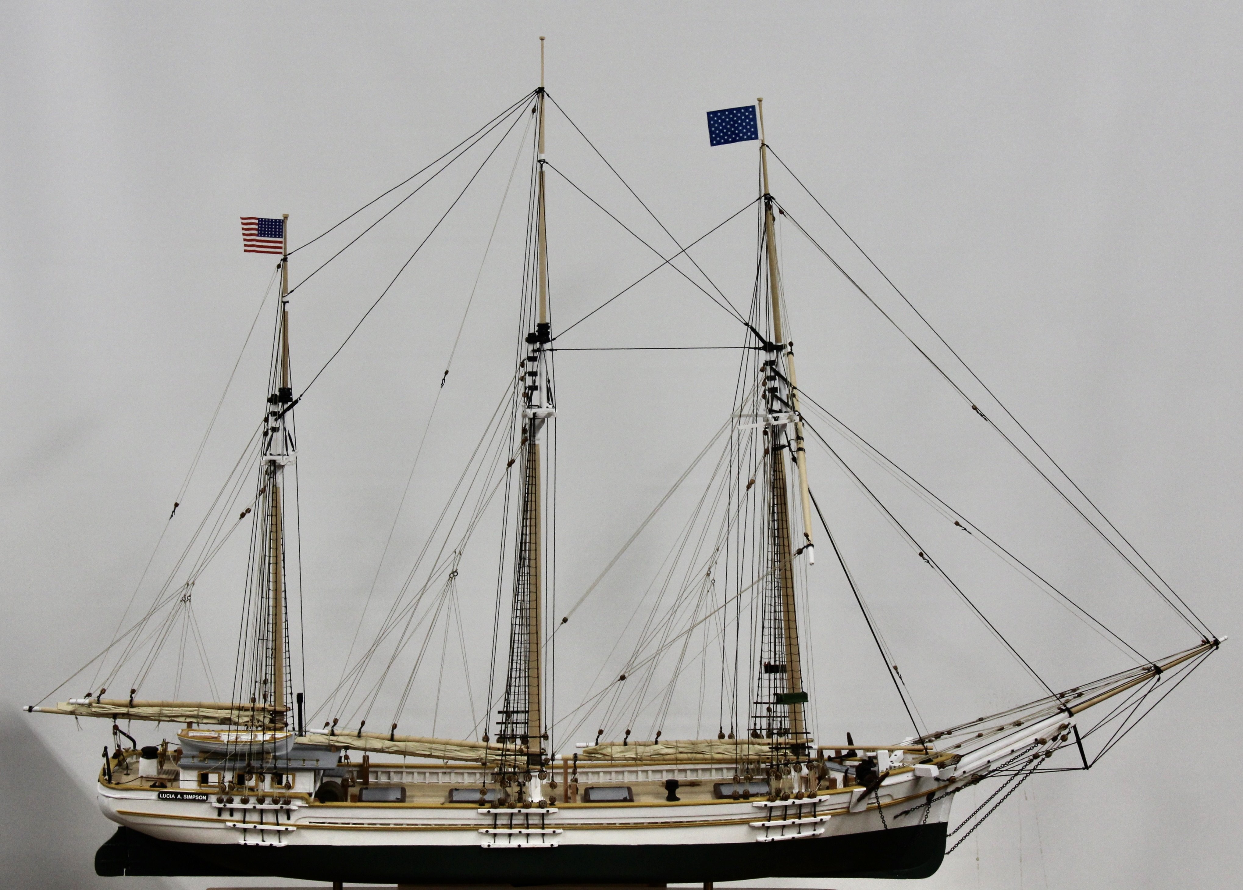
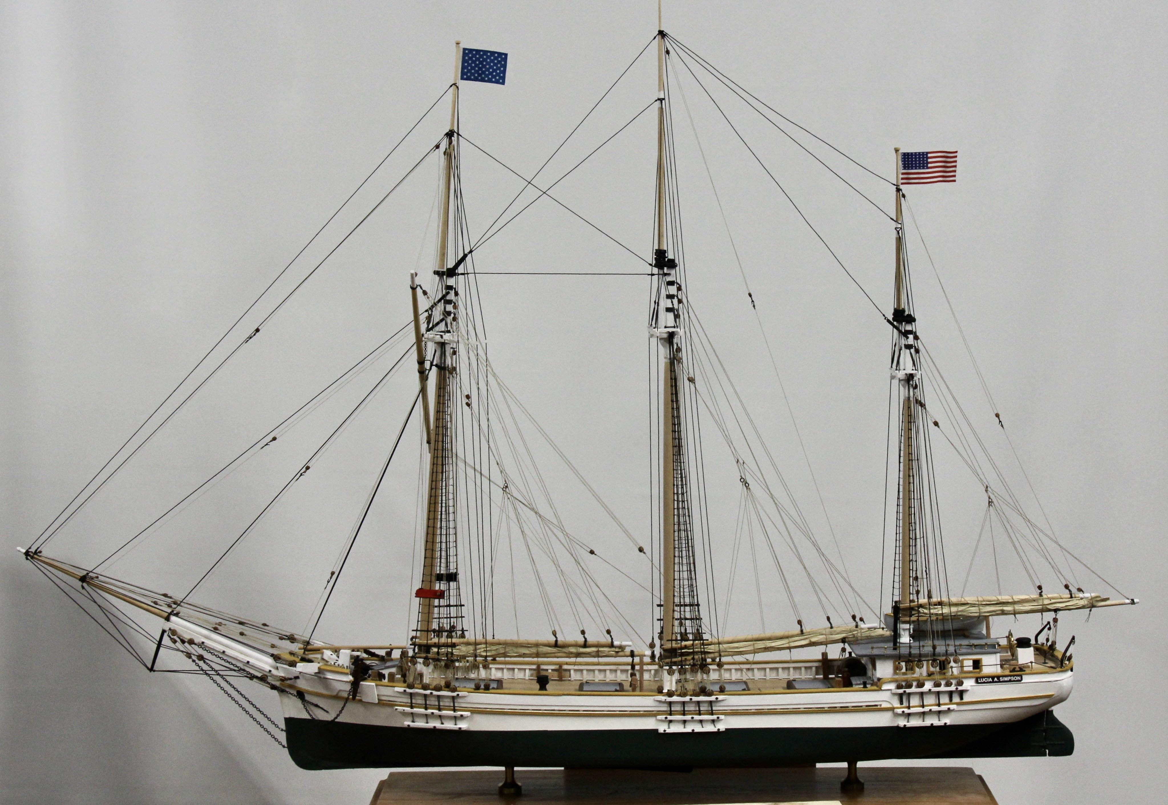
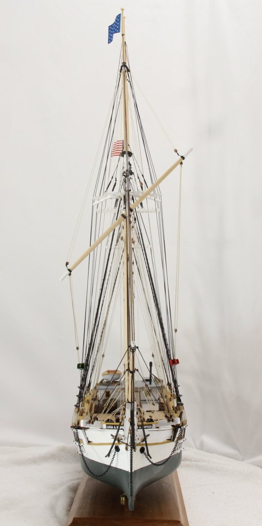
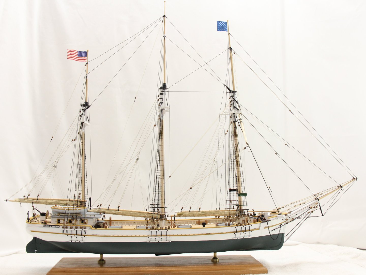
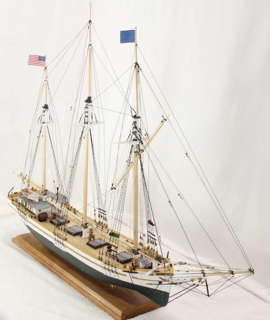
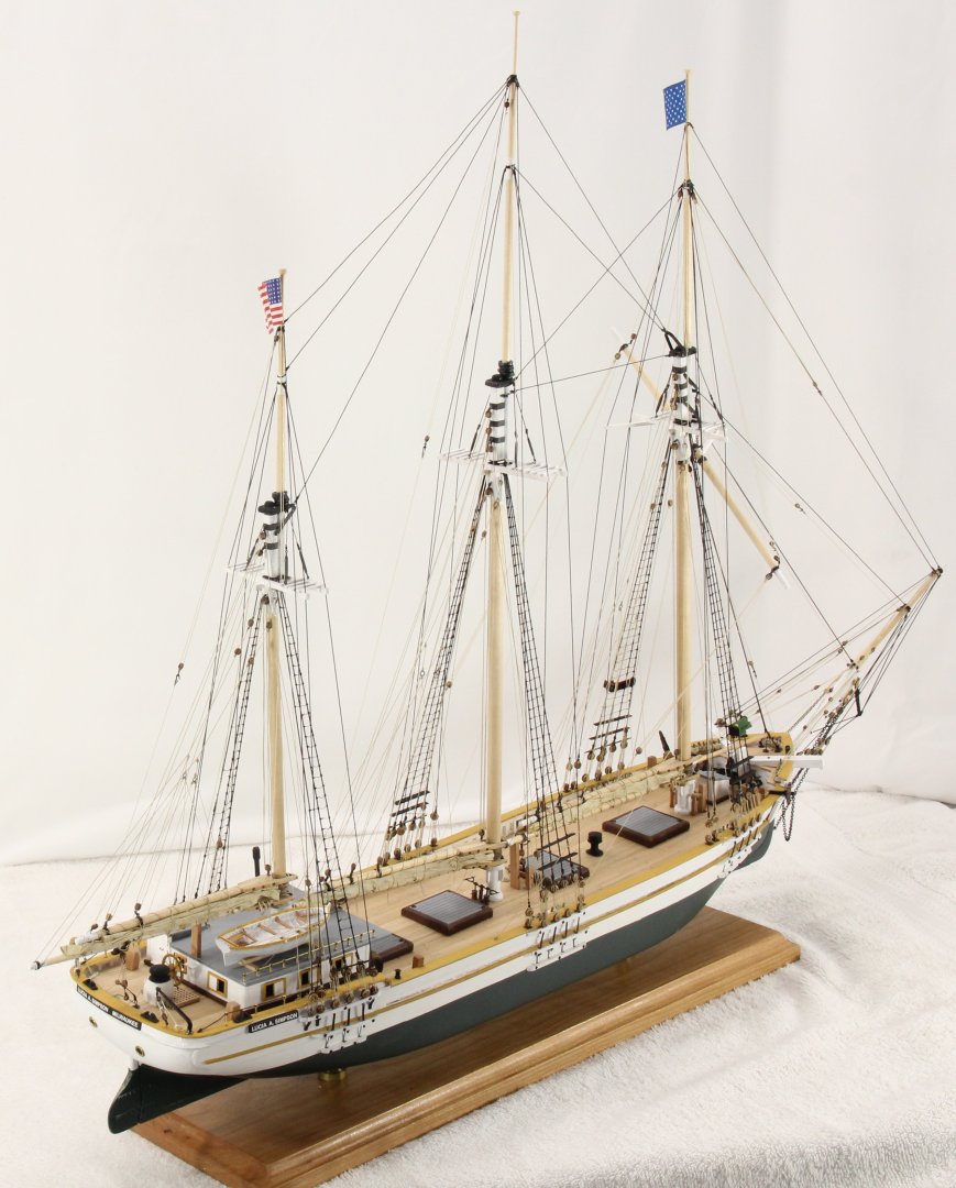
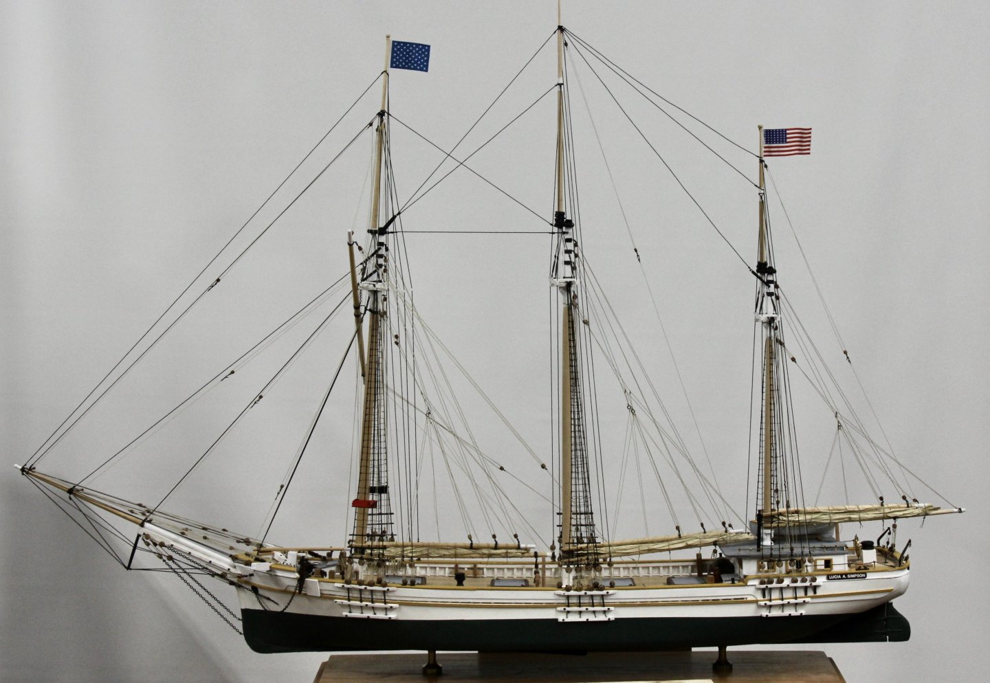
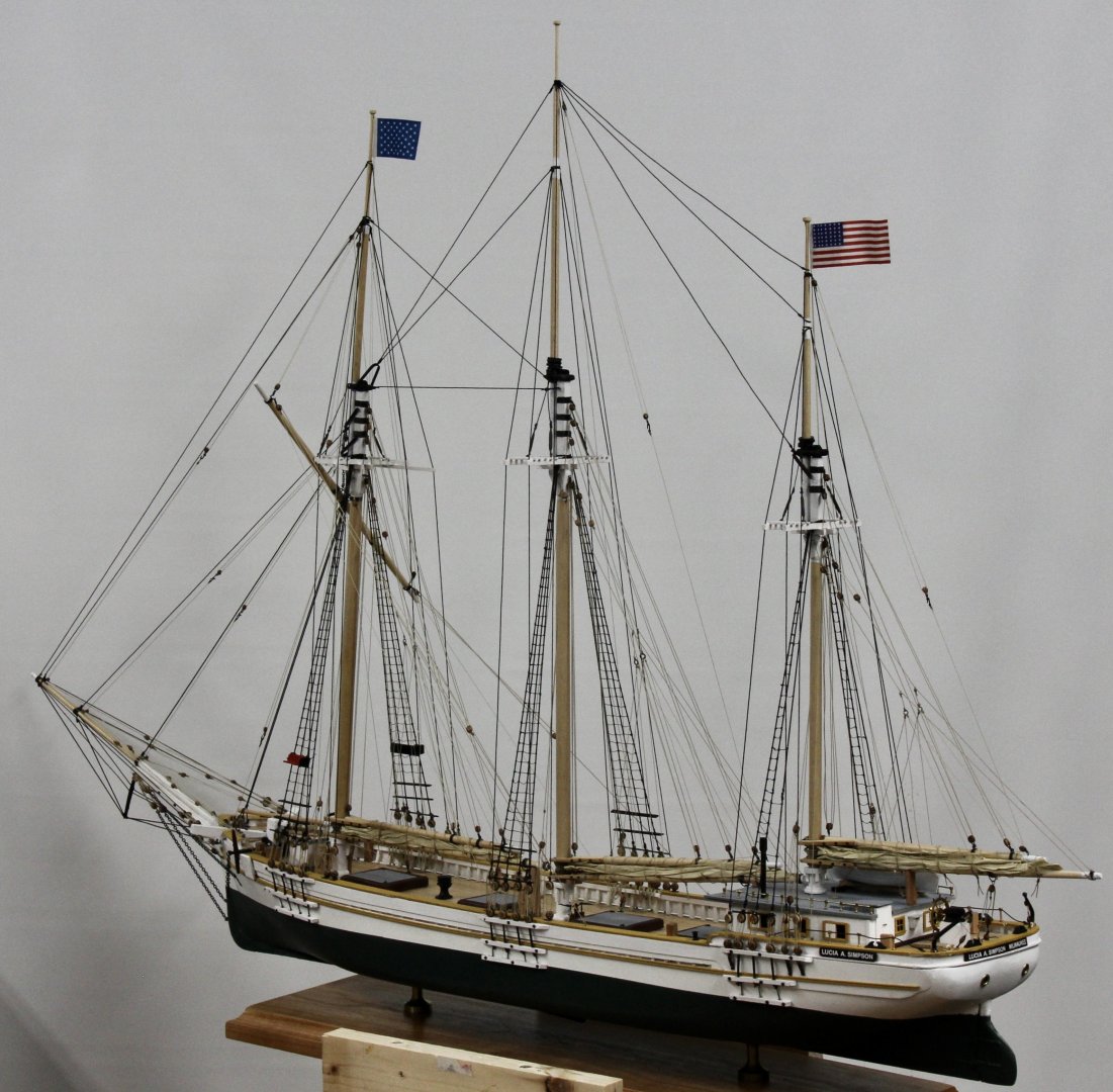
Thanks everyone. She is entered in the NRG Photo Model Contest and these are the pictures I submitted. The eight views (sides, bow, stern and quarters are "required" photos, the others are optional but I thought it useful to show some of the details. We will she how she looks to the NRG judges.


- 121 replies
-
- 5
-

-

-
- Lucia A Simpson
- AJ Fisher
- (and 1 more)
-
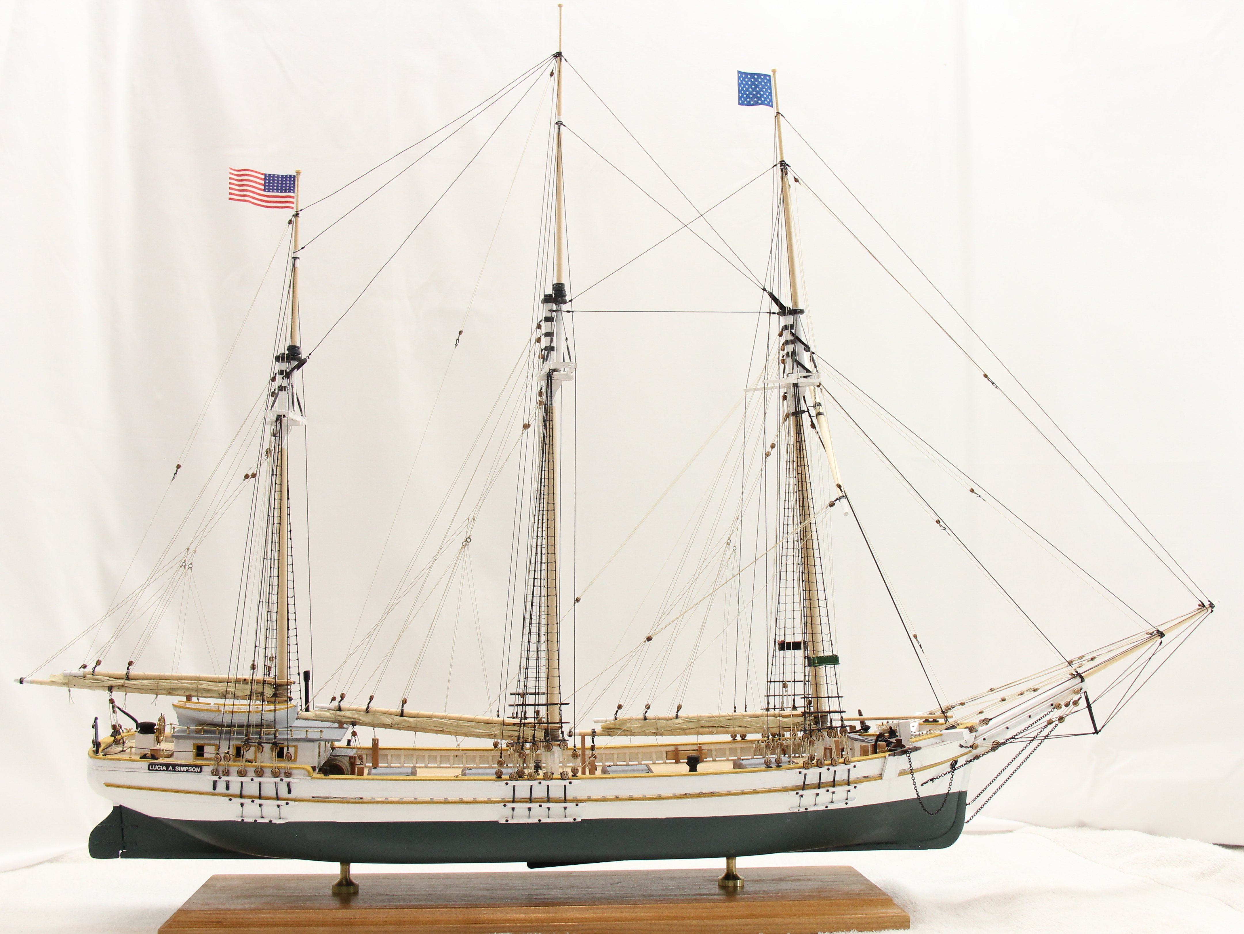
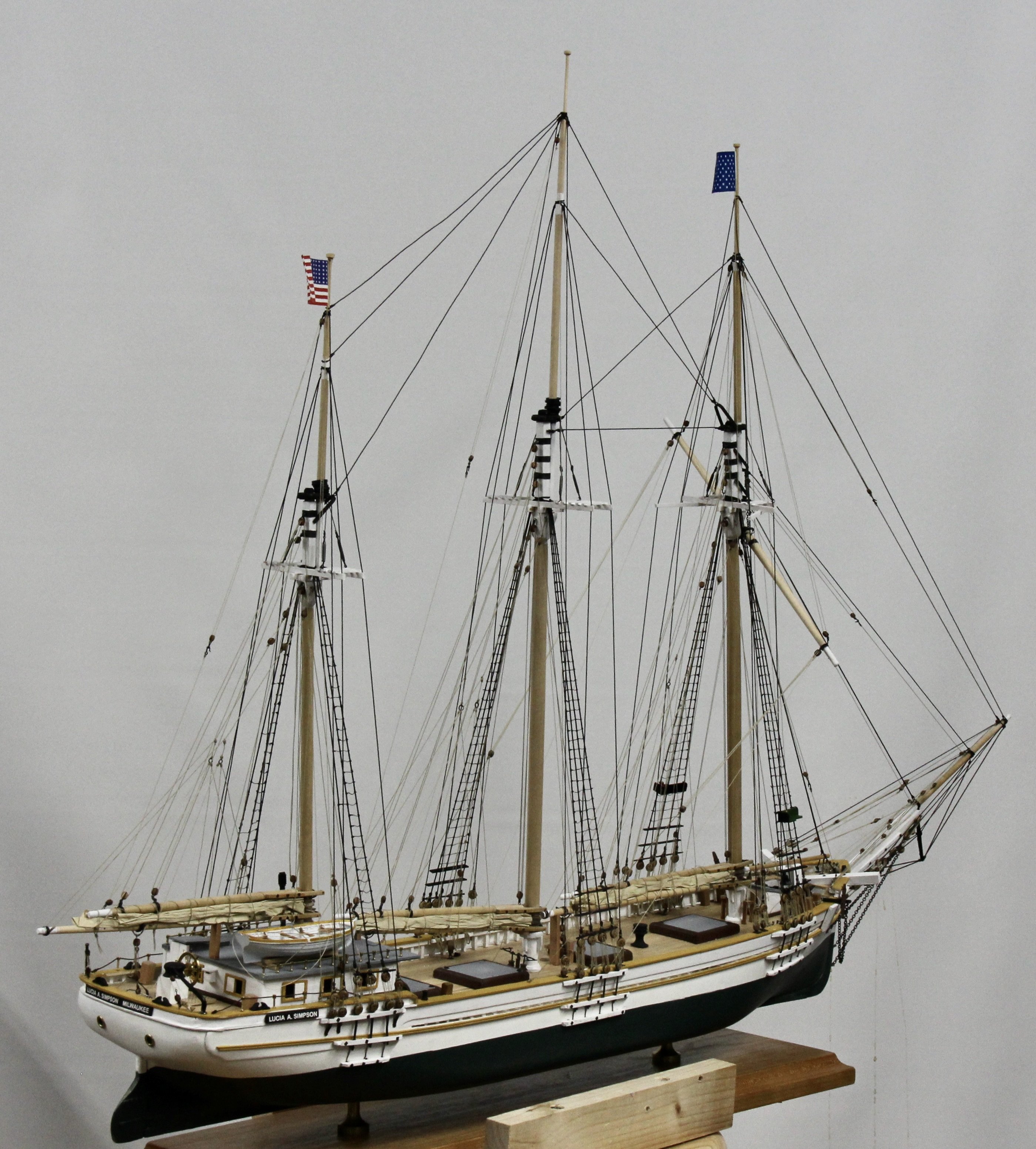
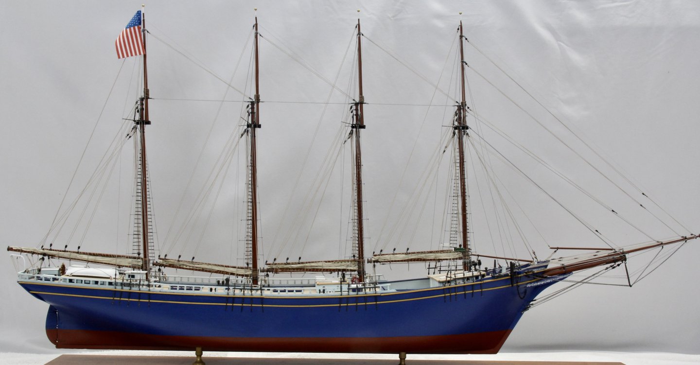
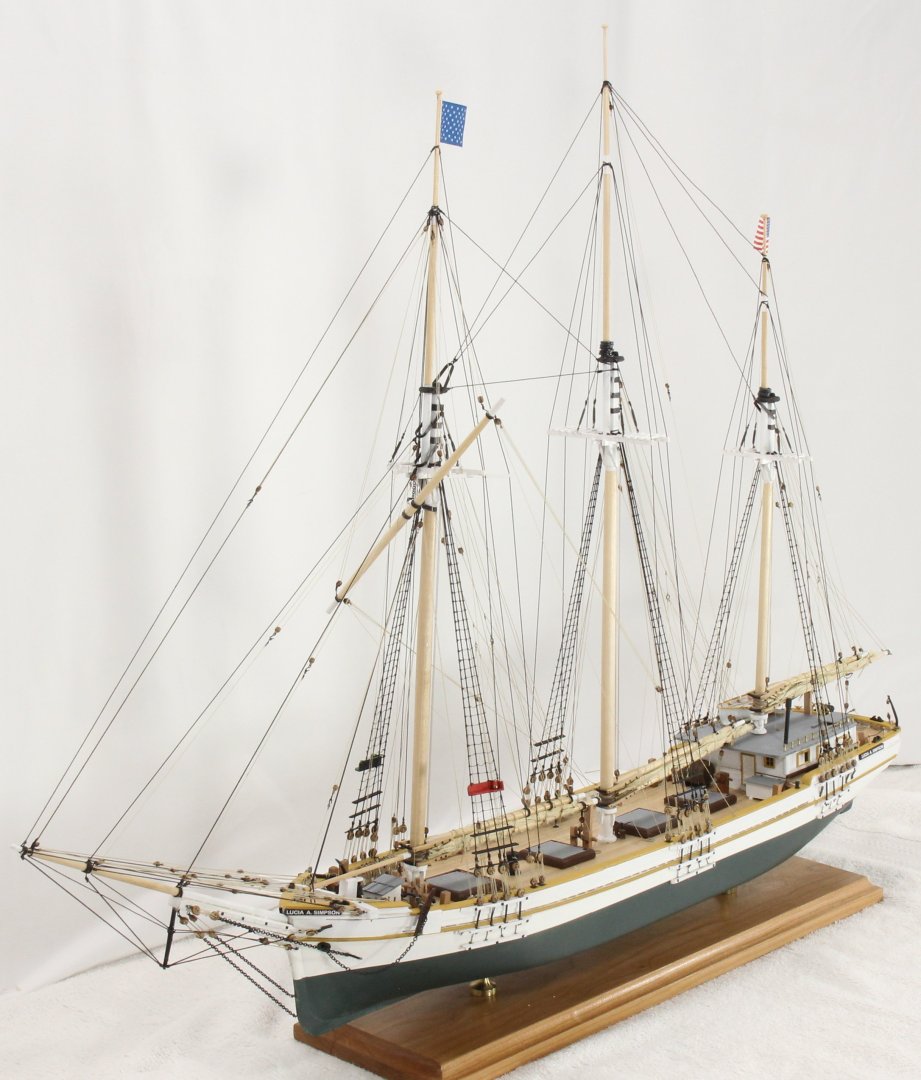
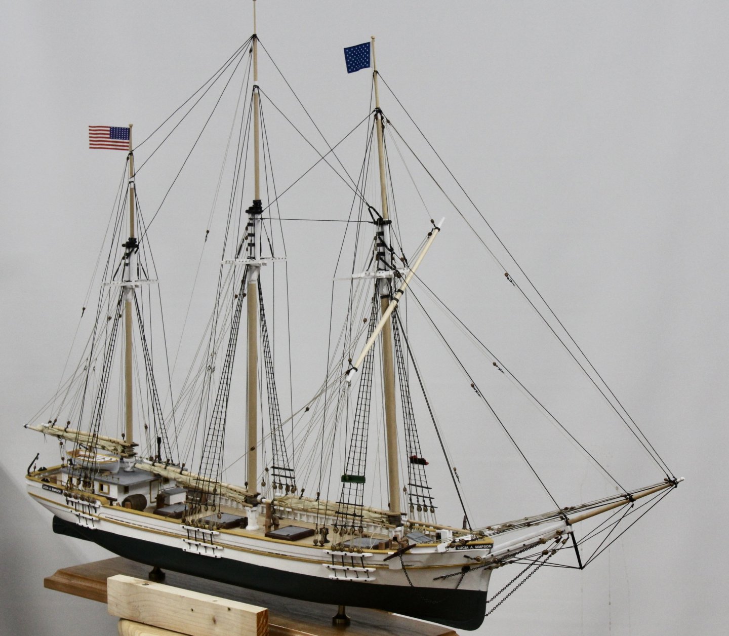
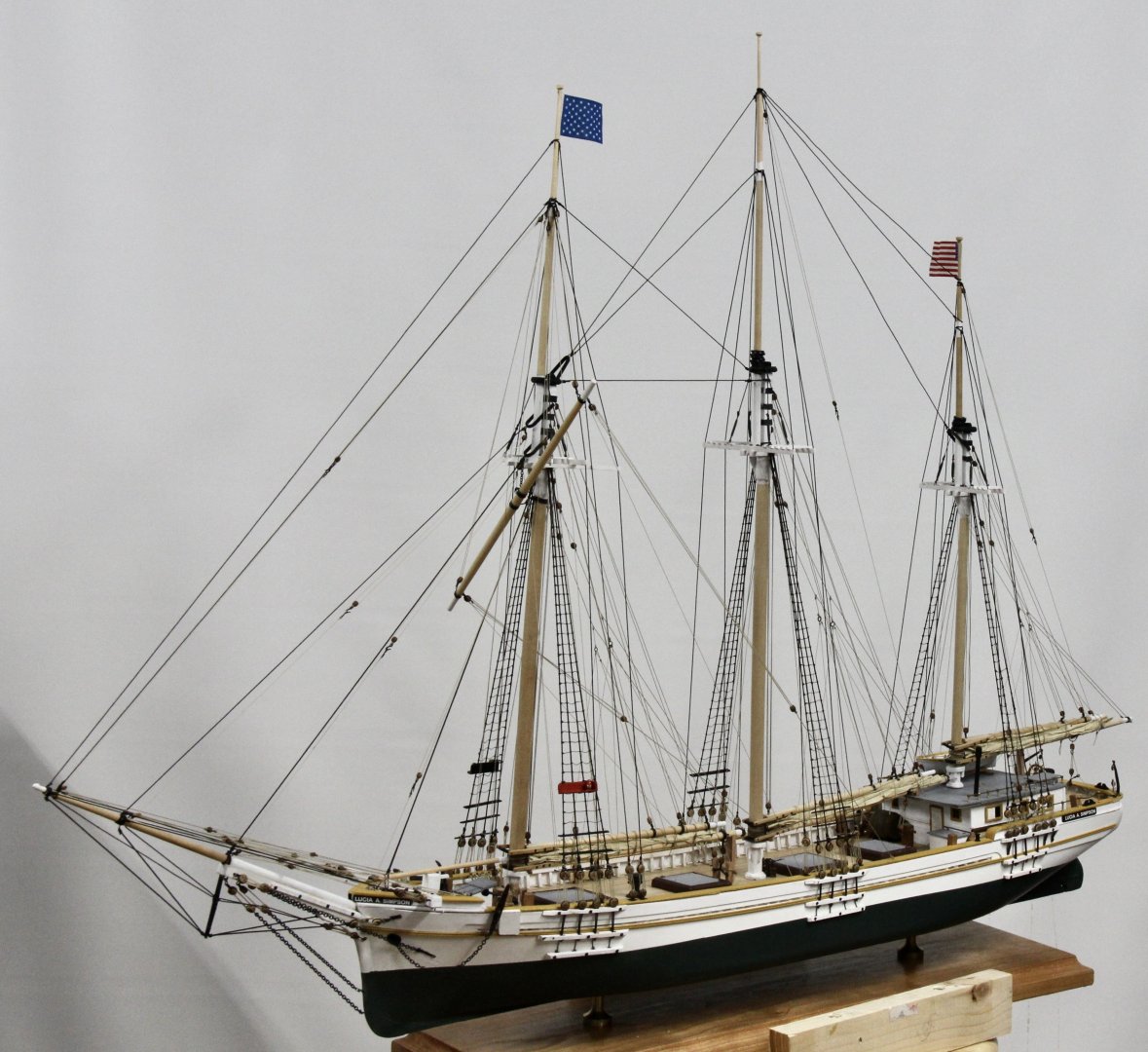
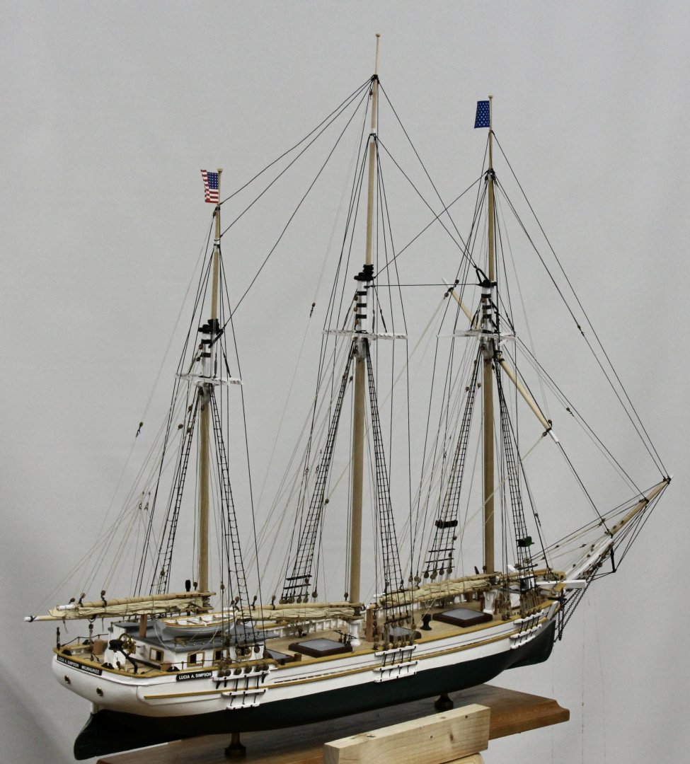
I declare the Lucia A. Simpson FINISHED! Here are some pictures of the ship as a whole. Now I need to clean up the workbench so it can become ma photo studio. Hopefully I can use my Canon E-60 to good effect once I get more/better lighting.

- 121 replies
-
- 7
-
-
-
- Lucia A Simpson
- AJ Fisher
- (and 1 more)
-
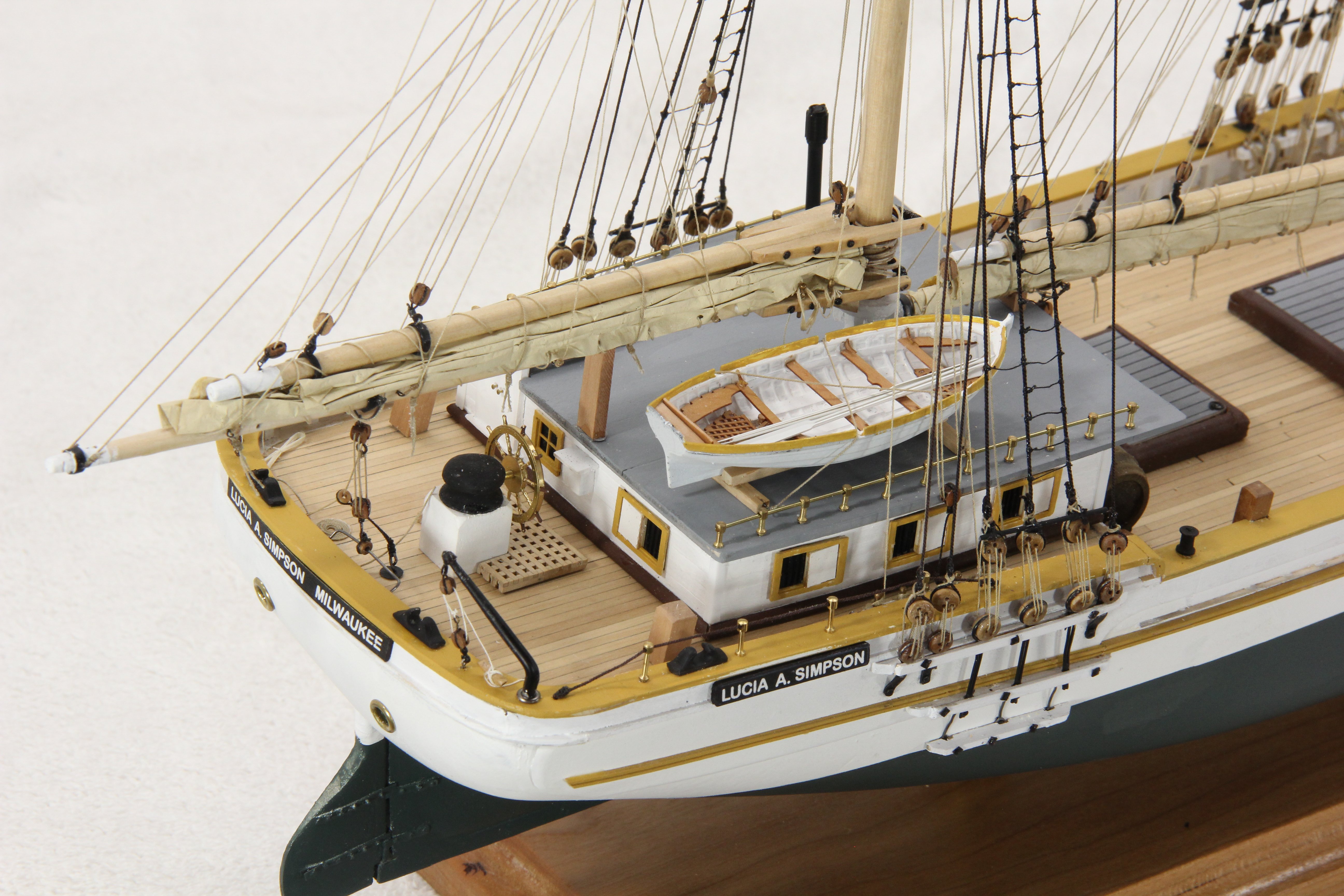
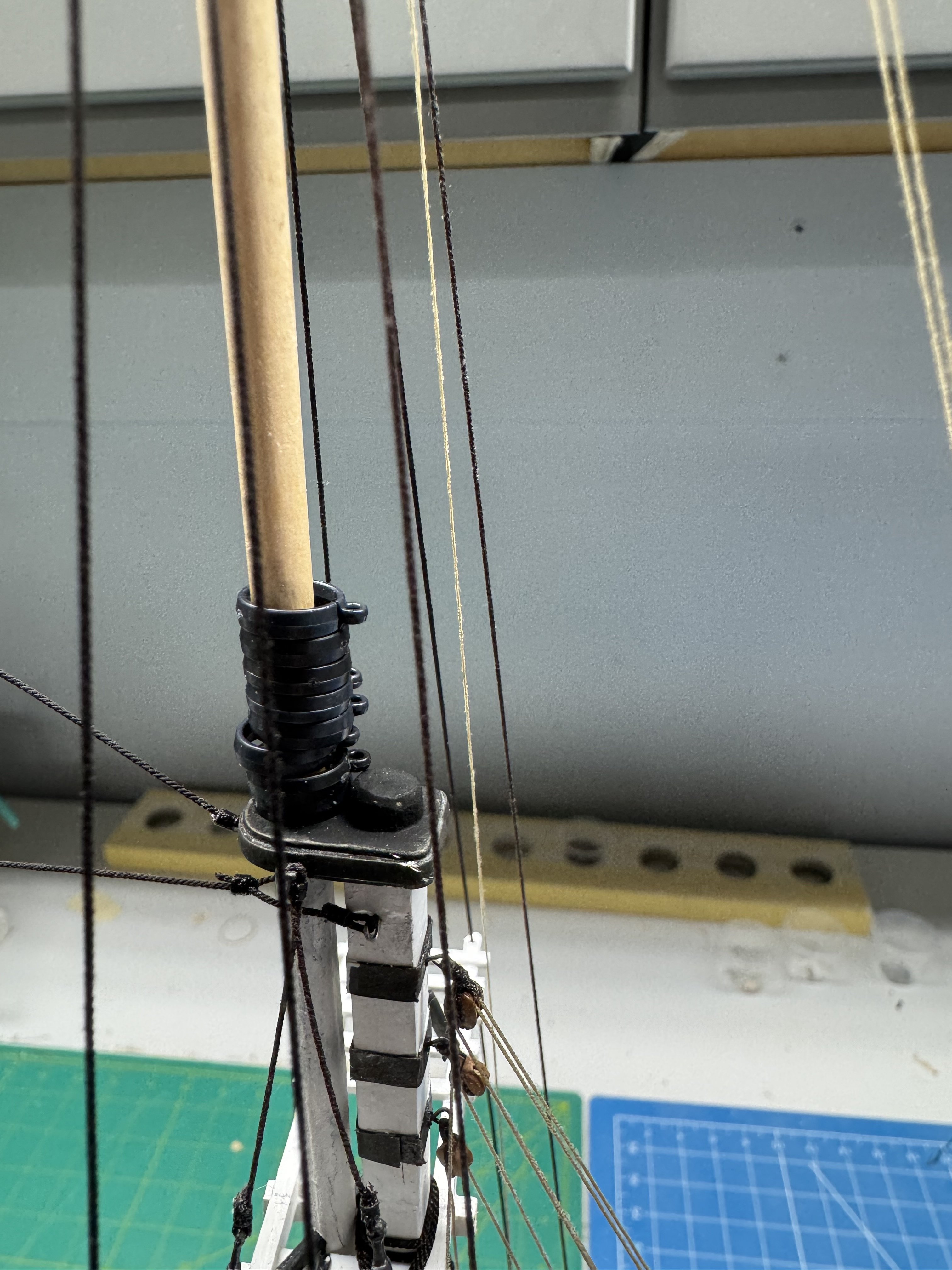
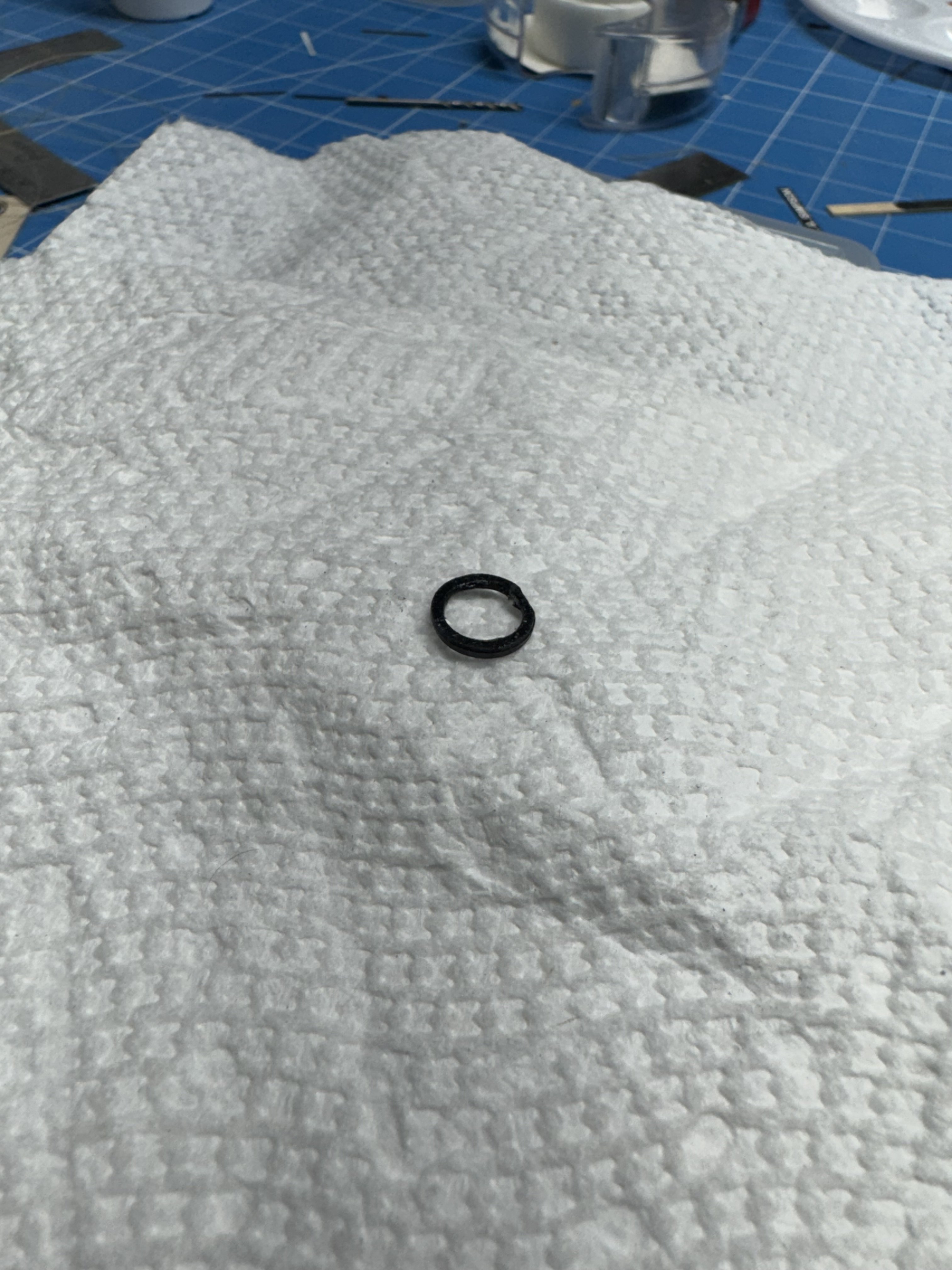
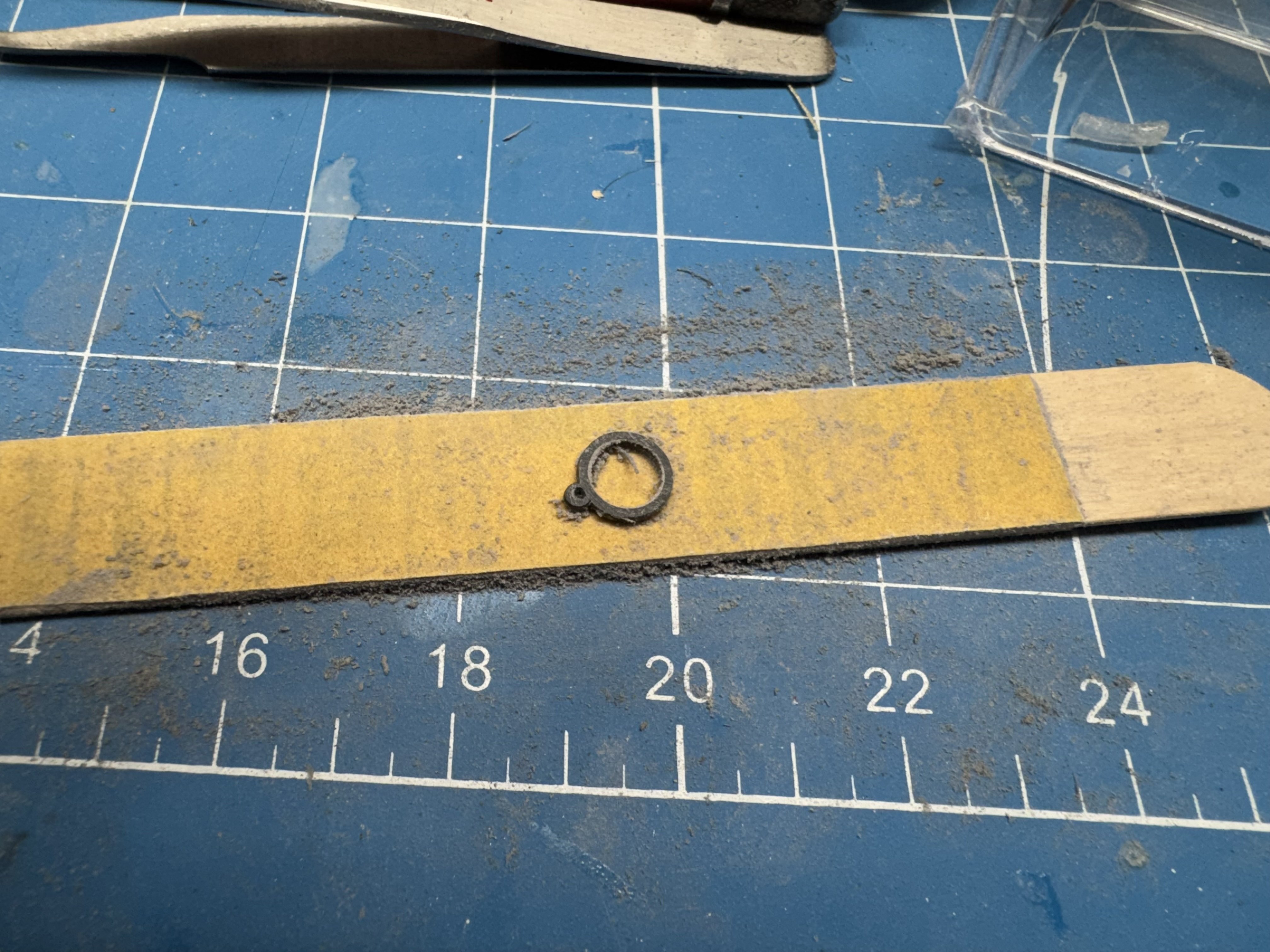
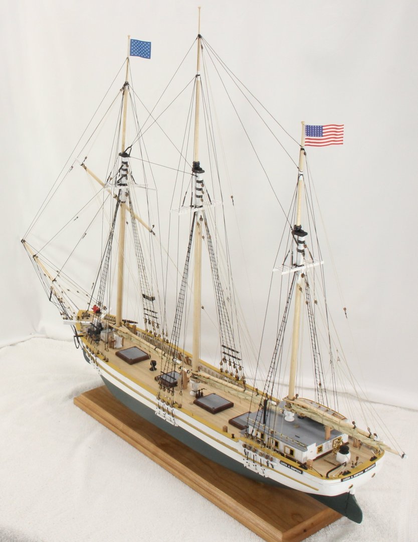
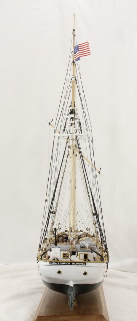
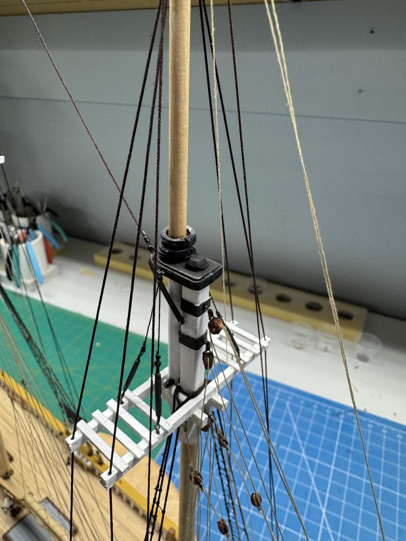
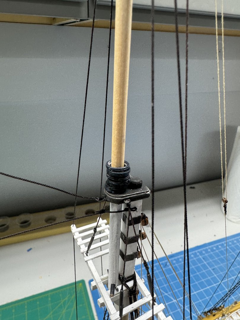
I my haste to get the top masts in place I forgot that there are mast hoops for the topsails on the main and mizzen masts. I had some 5/16" and 1/4" wooden mast hoops that are laser cut and thought MAYBE I could cut them open and TWIST them around the top masts and live with the small "crack" in the hoop. Not in my lifetime, the hoops are so fragile there was no may I could get them around the top mast in less than two pieces. I rummaged through my "parts bin" and found some plastic mast hoops in black. They are about .095" thick and have a ring for connection to the sail. I cut them right next to the attachment ring and they could slide around both top masts. I used some liquid plastic glue to attempt to glue them back together but was unwilling to hold the end together by hand for the glue set time which seemed like hours. The liquid glue did restore more or less the black finish that cutting them had disturbed. Here is what the main top mast looked like. Compared to the mast hoops on the lower masts they are much thicker and the ring attachment stands out. So, since I had enough of the plastic hoops to make another set I started by sanding the hoops down to approx .05". Still thicker than the lower mast hoops but about as thin as I could go without risk of them getting "crooked" with one side/end noticeably thicker/thinner than the other. Don't ask me how I know this. I cut the ring off and used the plastic glue to restore the finish playing particular attention to the outer edges as that is really all that can be easily seen. Here is the mizzen mast with the new, smaller hoops without the ring. They are still black but not nearly as noticeable as the larger ones. Short of painting them brown this is the best I can do. I looked at the other schooner i have built and all have mast hoops on the top masts, that carried topsails. And here is the main - looks much more "in scale" than before (IMHO).


- 121 replies
-
- 4
-
-
- Lucia A Simpson
- AJ Fisher
- (and 1 more)