HOLIDAY DONATION DRIVE - SUPPORT MSW - DO YOUR PART TO KEEP THIS GREAT FORUM GOING! (Only 72 donations so far out of 49,000 members - Can we at least get 100? C'mon guys!)
×


cdrusn89
-
Posts
1,915 -
Joined
-
Last visited
Content Type
Profiles
Forums
Gallery
Events
Everything posted by cdrusn89
-
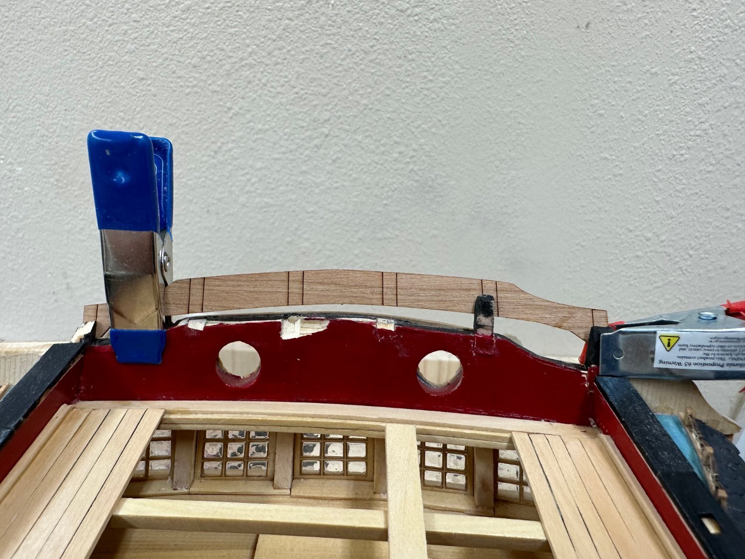
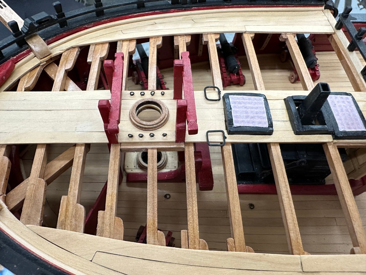
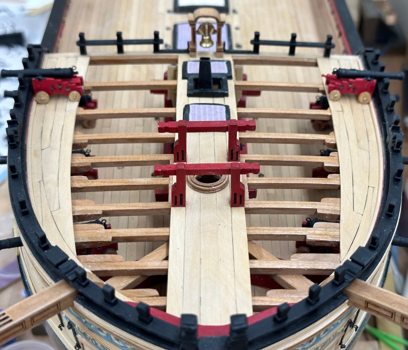
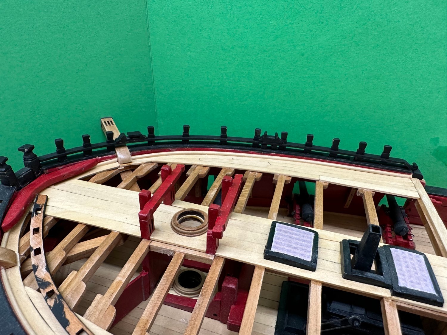
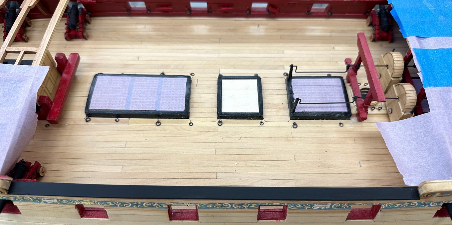
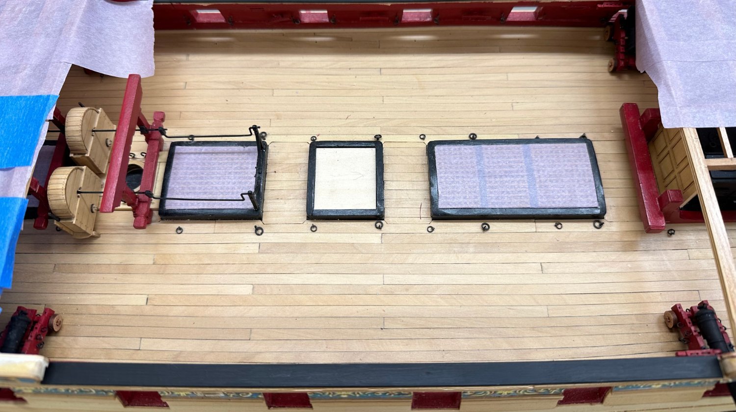
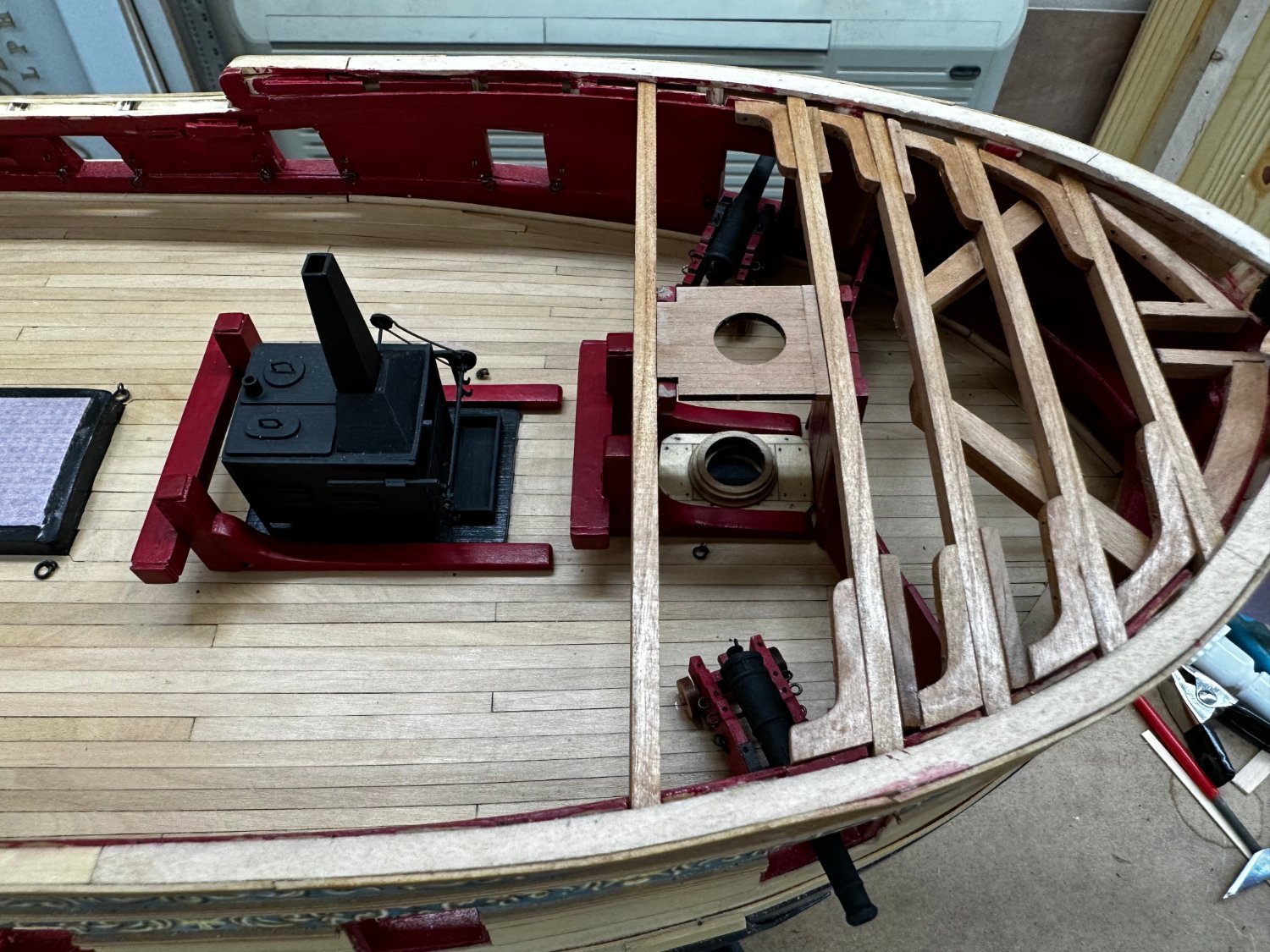
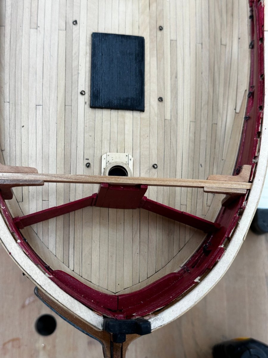
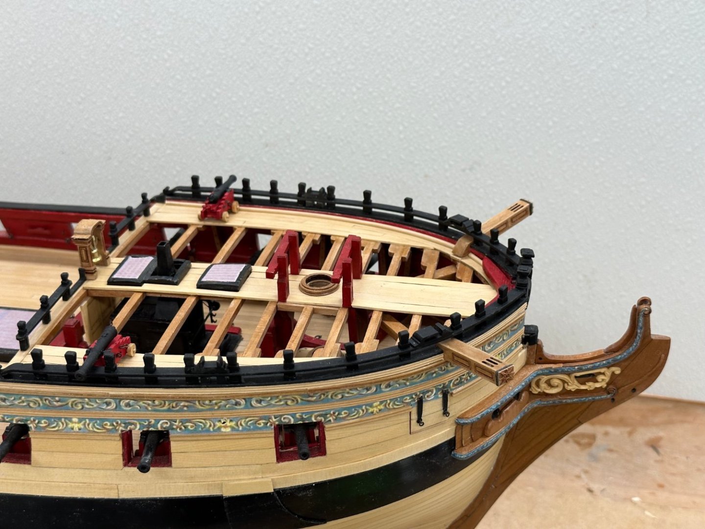
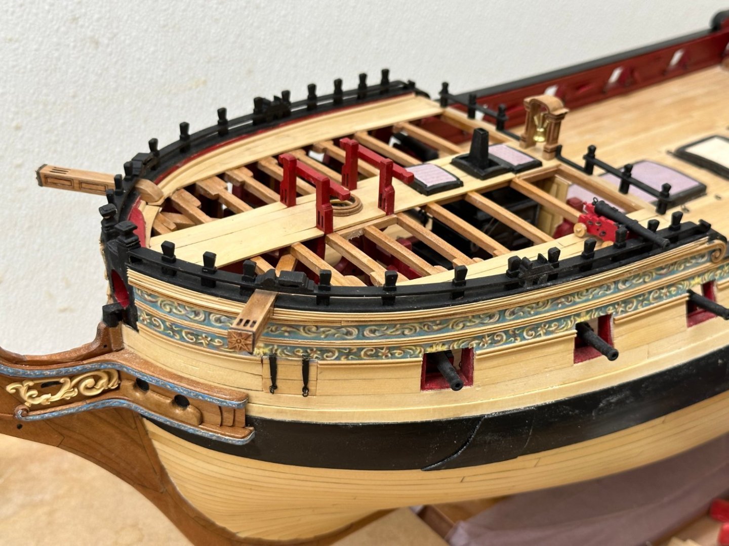
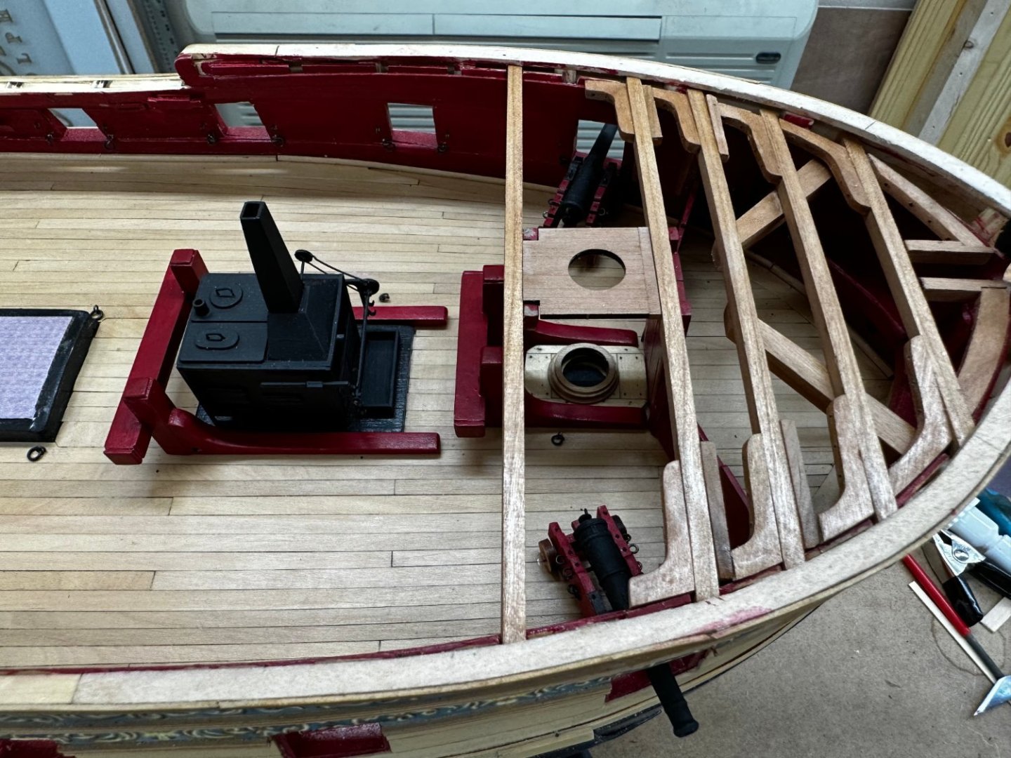
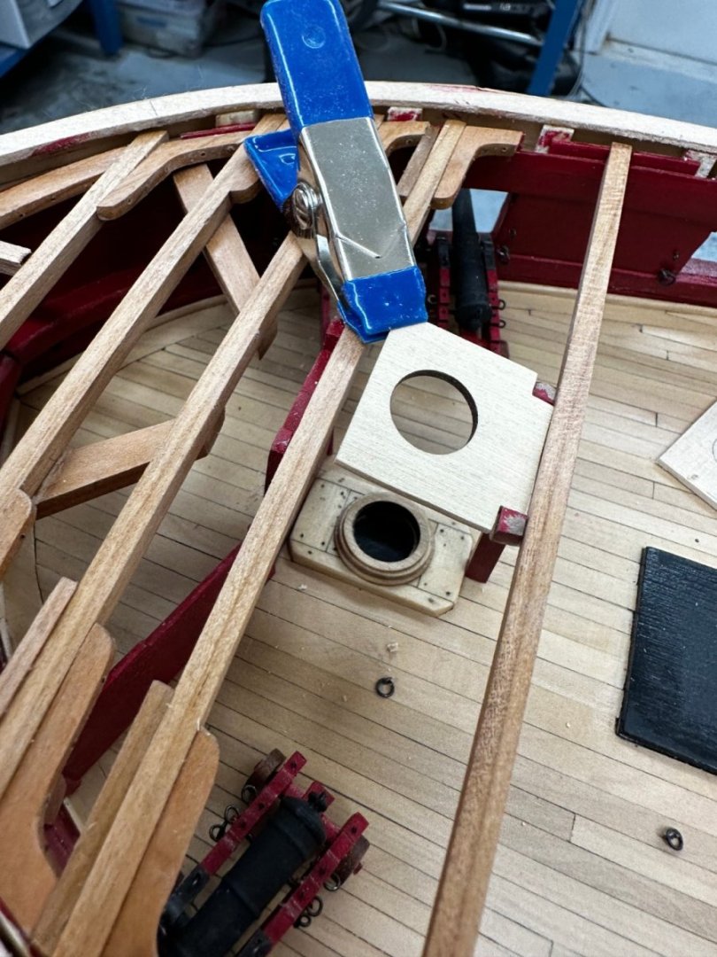
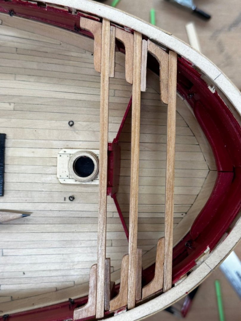
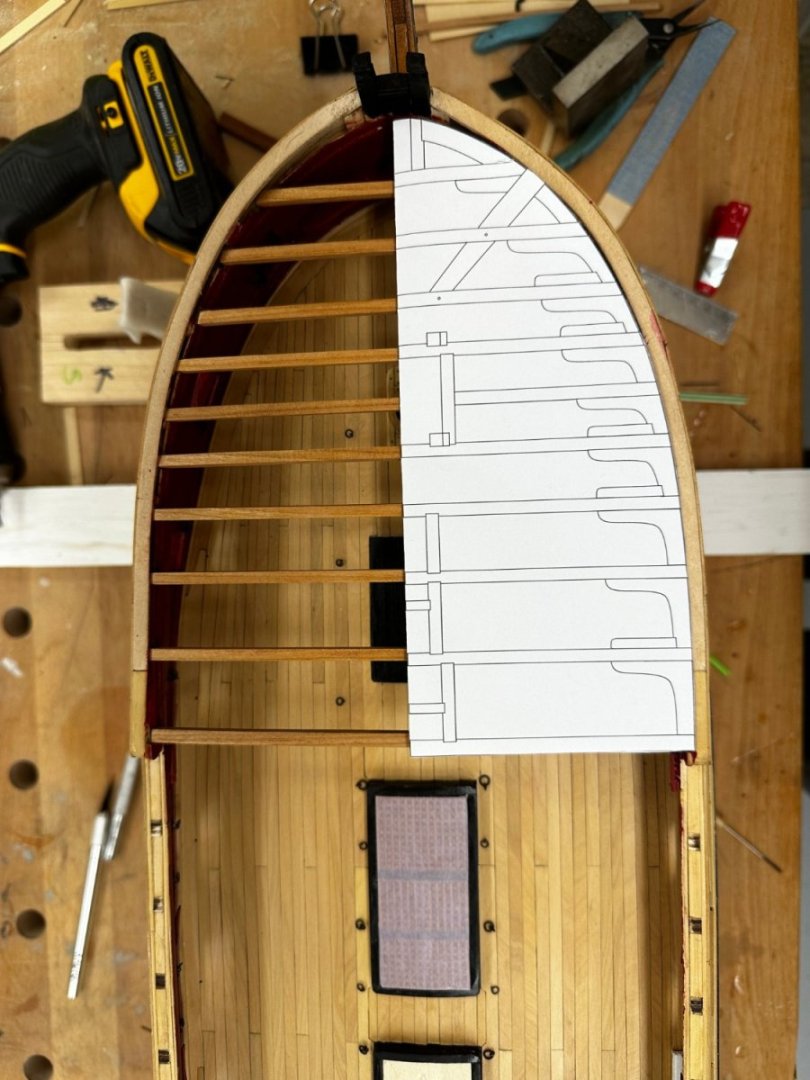
 I completed the planking down the port and starboard sides of the qdeck and have two coats of WoP applied (a third goes on today). I have the hatch coamings and the capstan partner installed and the mizzen bits in place (glue is drying as we speak). I will start planking between and around these items shortly although I am still deciding on whether or not to plank over the great cabin (aft of the last hatch). I am trying to find 1/48th scale furniture (a desk, table and chairs might work out) to place in the great cabin and then not plank from the aft hatch to the transom. If my search is unsuccessful I am still toying with not planking that part as I am not sure it adds anything and would be another area to show my ineptitude at planking where tapering is required (and looking at the template every plank must be tapered). So here is the qdeck at it stands now. However, before I start the planking I need to address a near disaster at the stern. An inadequately stored piece of 1 X 12 pine fell on the stern and broke off all of the timberheads on the transom. In at least one case it took part of the transom with it. At the moment I have the two port most timberheads reattached and am trying to figure out how to get the others done and then patch up the damage to the transom. While I am at it I will get the timberheads trimmed down in preparation for the aft rail but it may take some effort to get the timberheads reattached and in one case I may have to "start from scratch". I have decided to deal with this before I start the planking. Here is what the stern looks like with the stern rail template in place and two of the six timberheads "back in battery" more or less.
- 389 replies
-
- 5
-

-

-
- winchelsea
- Syren Ship Model Company
- (and 1 more)
-
Fo'c'sle is now really complete thru Chapter 9 - added the spanshackles and eyebolts. Working the qdeck planking and assembling the hatch coamings so I can start the centerline planking.

- 389 replies
-
- 6
-
-
- winchelsea
- Syren Ship Model Company
- (and 1 more)
-
Chapter 9 is complete on fo'c'sle except for the spanshackles and the eyebolts on the mast partner. I am waiting until all the paint is dry before I create any more wood shavings/sawdust. Boy that flat black paint seems to attract dust like a magnet. So here is what it looks like at this point. I added some cannon (just sitting there no glue/pins yet) which I originally made for the Confederacy kit (I did not like the Britannia metal cannon in the kit) only to find out when it came time to install them that there were too tall to fit through the gun ports. So at least I can use 6 or 8 of them on the Winnie.

- 389 replies
-
- 4
-
-
- winchelsea
- Syren Ship Model Company
- (and 1 more)
-
I also broke both pieces, one of them twice. Having bought both cherry and AYC packages for Chapter 9 I found the cherry pieces to be less susceptible to breakage and used thin CA on the entire piece before handling it too much to try and stiffen it up some. I am not sure it helped but I did get the starboard side done without breaking the cherry piece. I "think" I have the port side ready for final install and have not broken that one yet.
-
Starboard side fo'c'sle railing is complete including the spanshackle cleat and cat block. I did have one significant issue early on the in that the outside bulwark on the fo'c'sle was too short. The waterway would have been just above the top of the outboard bulwark WITHOUT the deck planking. A similar issue on both sides (thank god - not sure what I would have done if it were only on one side). I have no idea how this came to pass beyond my lack of attention to details at some point or points during the hull construction. I added a 3/32" "filler" on top of the existing bulwark to permit the planking/waterway combination to reach just to the top of the bulwark at the aft end. I added another "layer" of fancy molding to cover the outboard edge. Inboard I just painted it red. Looking at the outside the sharp eyed can see the extra row of fancy molding and on the inboard side you can just see the extra "filler" at the aft end. It does not look terrible (IMHO) but does beg the question of what impact this might have on the work yet to be done at the bow. On to the port side and then the qdeck planking.


- 389 replies
-
- 2
-
-
- winchelsea
- Syren Ship Model Company
- (and 1 more)
-
Thanks Matt - I think now that it is done that maybe the CA was "belt and suspenders" so I will probably dispense with it on the other side. I still have the port side fore railing and the decking on the qdeck to go in Chapter 9. Chapter 10 maybe off in the future somewhere as I am moving to a new house on 8/15.
- 389 replies
-
- 1
-
-
- winchelsea
- Syren Ship Model Company
- (and 1 more)
-
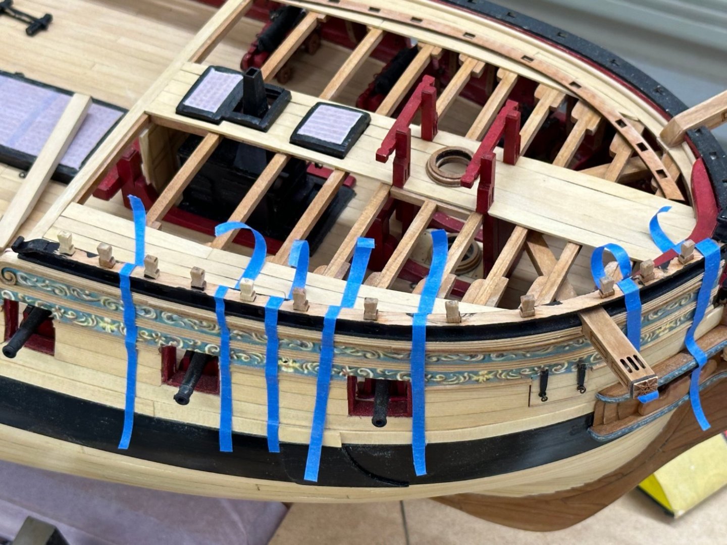
Now that the decking is complete the next step is the timberheads and railing on the Fo'c'sle. I would mention that the railing piece is quite fragile (don't ask me how I know) so care must be taken getting the timberheads installed in the rail. Trying to get the railing in place with all the timberheads remaining in their "holes" provided to be harder than you might think. To avoid having to do it on the model I painted the bottom and sides of the rail and the part of each timberhead below the rail off board. Then I assembled the rail and timberheads upside down and painted the junction between the rail and the timberheads with the flat black paint to attempt to get them "attached" but not "glued". Once the paint was dry the timberheads stayed in place while the rail was turned right side up placed on the model. I used white glue in the holes in the lower rail to attach the timberheads to the hull and one by one seated the timberheads into the holes. I had to break the paint joint on a few to get them seated and vertical but overall in went "okay". I used stripes of blue masking tape to apply some pressure to keep the timberheads against the hull. It was the only solution I could come up with given the space and other constraints in this location besides using my hands and sitting there for half an hour while the glue set. I was reluctant to use CA to attach the timberheads to the hull because I thought even the thick might set too quickly to allow for whatever adjustments might be necessary. After the timberhead/hull connection is set I will add a drop of thin CA to the joint between each timberhead and the rail and then CAREFULLY paint the top of the rail and the timberheads.
- 389 replies
-
- 2
-
-
- winchelsea
- Syren Ship Model Company
- (and 1 more)
-
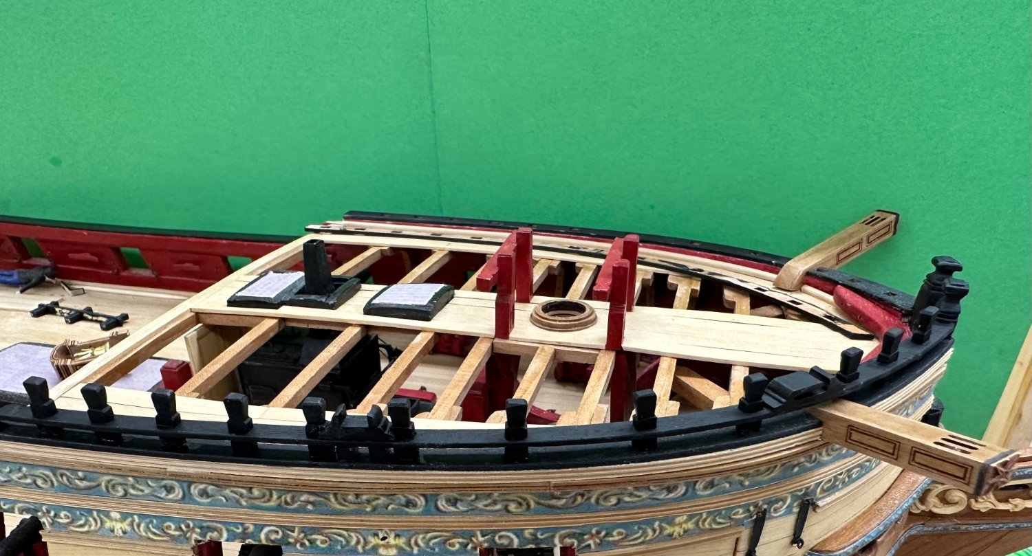
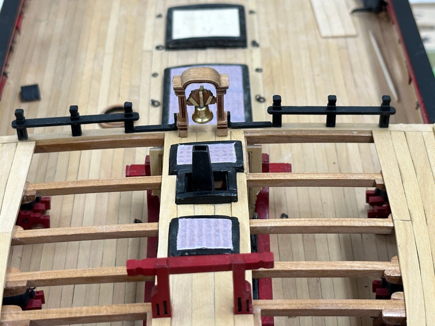
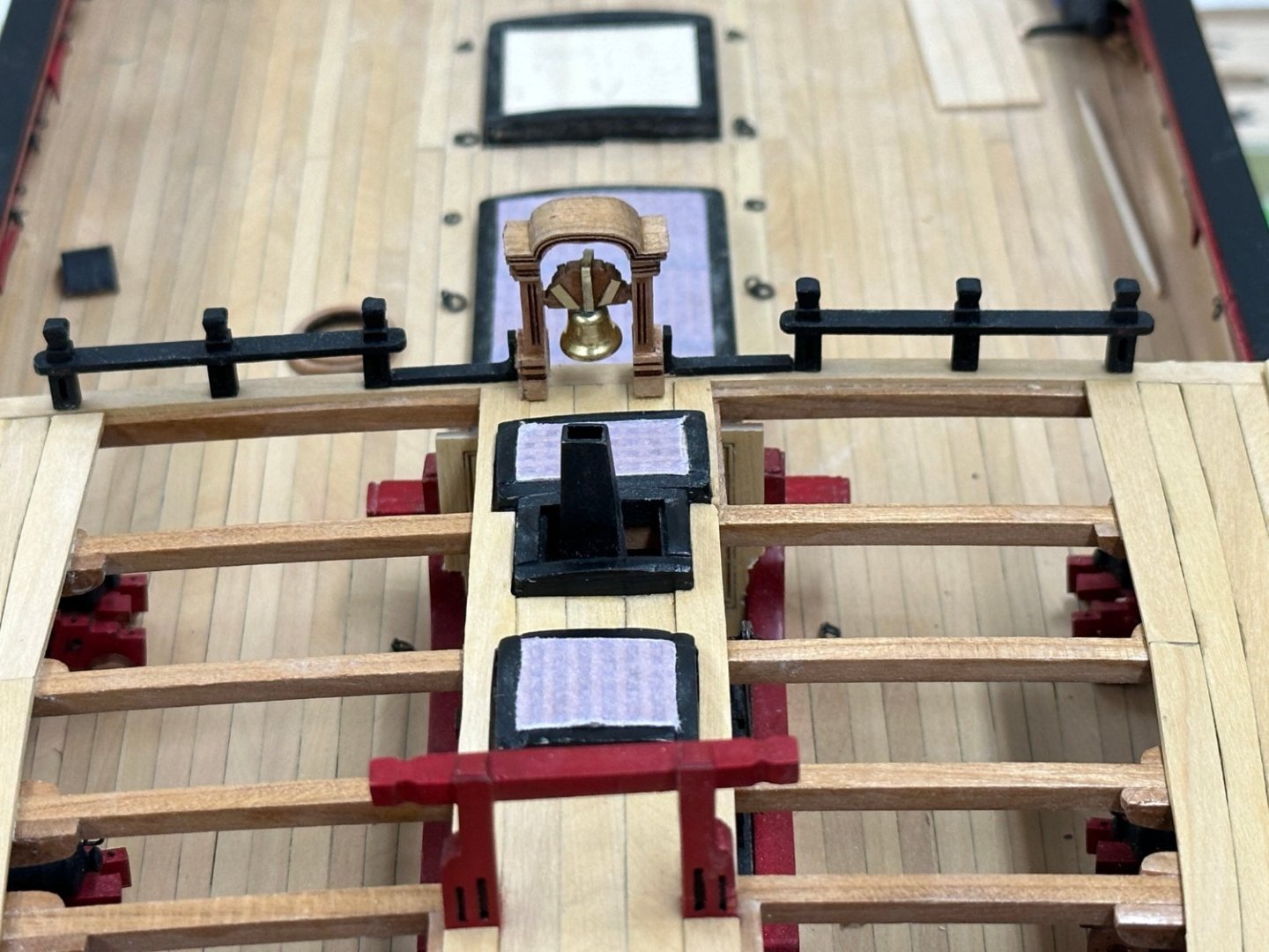
Dry fit of the belfry and rail. This is the cherry belfry which I have decided is the one that will be mounted after the Fcastle rail is installed. Likewise I will use the cherry mast partners to keep the "theme" going. Working the cat heads now. Am really not looking forward to cutting into the bulwarks after so much work getting them finished. But....
- 389 replies
-
- 3
-
-
- winchelsea
- Syren Ship Model Company
- (and 1 more)
-
Fcastle decking completed - not the best job of locating hatches - the sharp eyed will notice the decking is somewhat thinner outboard of aft-most coaming. Even using the laser level it is hard (for me) to get the short pieces of decking lined up correctly, especially when there are obstructions in the way of the level light. Or I might have the hatch coaming slightly off-center, or maybe a bit of both. WoP next then deal with the cat heads and install the belfry and belfry rail. I have decided to go with the cherry belfry (and mast partners although I have not assembled them yet) to provide some contrast with the boxwood decking.
- 389 replies
-
- 2
-
-
- winchelsea
- Syren Ship Model Company
- (and 1 more)
-
Dry fit of the Fcastle coamings and the belfry rail. Need to fit the gratings and work on the deck planking. Starboard side outer planking done (in boxwood like the gun deck) - no WoP yet. By the way I am having trouble getting oil based WoP in the "Clear Satin" finish - this is what I have been using for the entire build but now all I seem to be able to get is "Warm Satin" in the oil base. I can get Clear Satin in the water based so will use that if I have to. I have a bit left of the old one but I have to thin it as it comes out of the can like honey.
- 389 replies
-
- 4
-
-
- winchelsea
- Syren Ship Model Company
- (and 1 more)
-
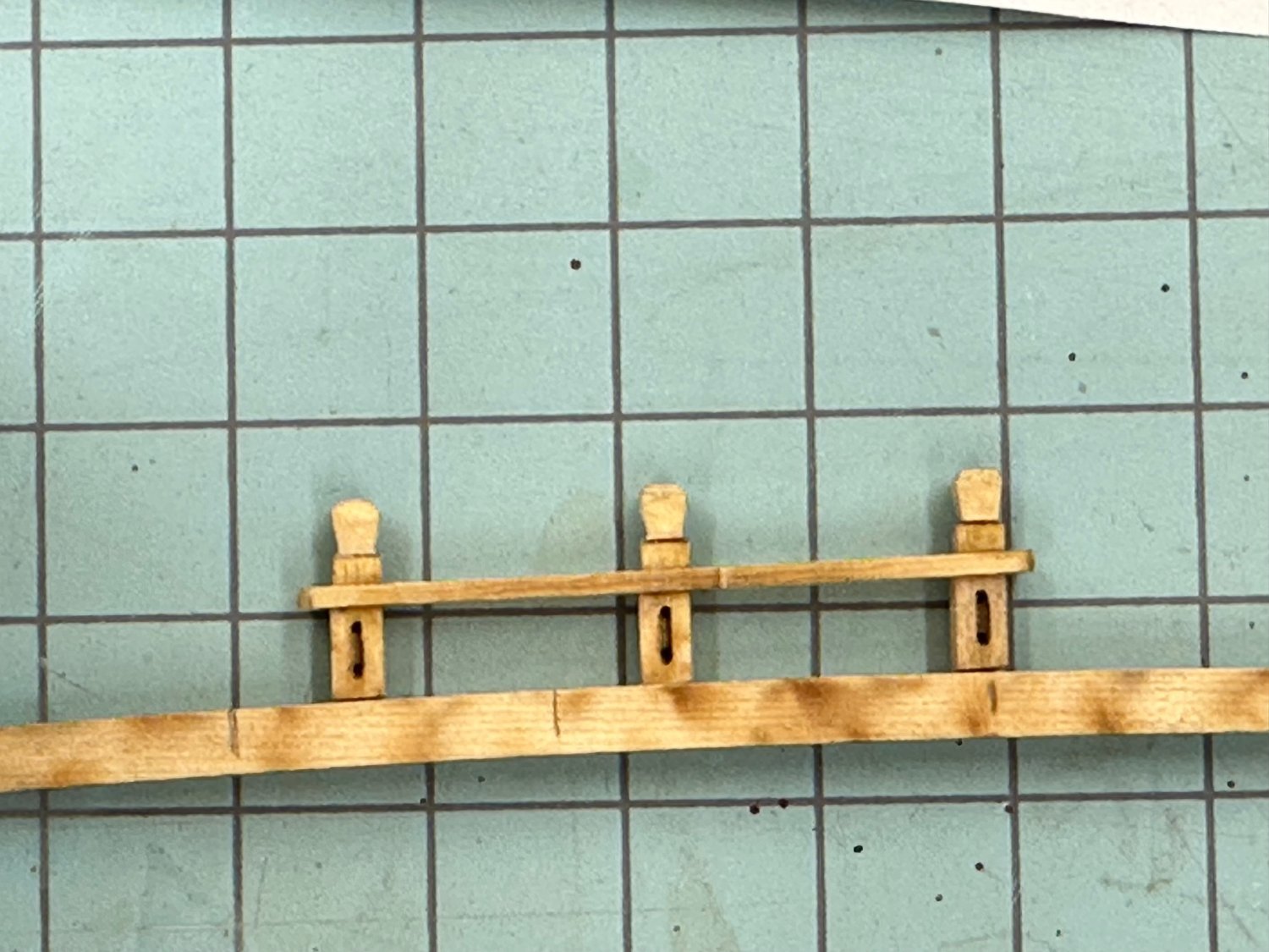
I was looking for a way to get the timber-heads in the belfry rail oriented vertically. The timber-heads have the base cut at the "appropriate" angle but I was trying to see what the orientation looks like BEFORE it goes on the model. So I got a spare deck beam (one of the long ones) and marked the center and then using the drawings marked where the timber-heads should be. Then I clamped the deck beam to the cutting sheet making sure the two ends were lined up on one of the horizontal lines. I inserted the timber-heads into the rail (after gently sanding the inside of the openings). Then I held the belfry rail on the deck beam at the marked location and gently moved the timber-head until it was aligned with one of the vertical lines while maintaining the rail against the "stop". Then using a thin CA applicator (old sewing needle with half the eye ground off) I put a drop of thin CA on the junction of the rail and the timber-head. Rinse and repeat. I have to get the planking on the Fcastle done before the belfry and rail are installed to avoid likely damage during the planking so it will be awhile before I see if this "worked" as planned.

- 389 replies
-
- 2
-
-
- winchelsea
- Syren Ship Model Company
- (and 1 more)
-
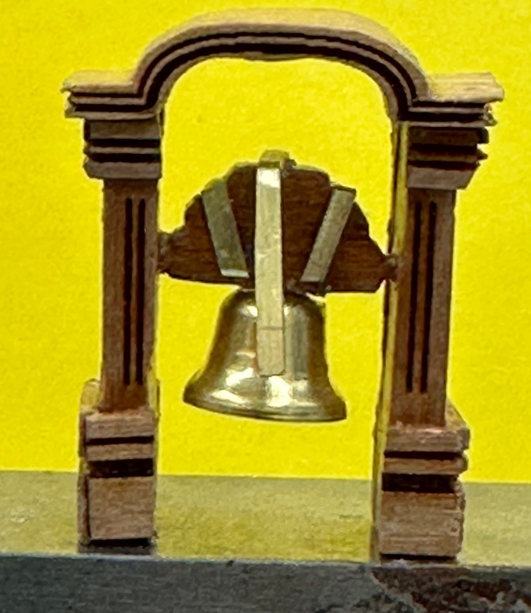
The cherry belfry. I am waiting on some parts for the AYC version. I haven't decided which will go on the model yet. It looks better "from a distance" and the top is not yet glued on. I am strategizing how best to do that.

- 389 replies
-
- 1
-
-
- winchelsea
- Syren Ship Model Company
- (and 1 more)
-
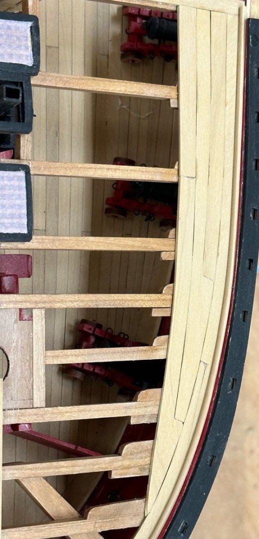
The "easy" stuff first - the cap rail at the waist. I did not have to do anything special to get the 5/16" strip to cover the rail so my fairing job (at least at the waist) must have been sufficient. Keeping busy with adding the inboard bulwarks while also building the belfry. Will fit the drifts and rounded rails as time and paint drying permits. Masking tape is to keep small pieces and sawdust out of the completed areas. Even my mini vacuum has a hard time getting into all the corners. Trying not to make cleaning up any harder than necessary.


- 389 replies
-
- 6
-
-
- winchelsea
- Syren Ship Model Company
- (and 1 more)
-
Chapter 8 completed fore and aft. On to Chapter 9
- 389 replies
-
- 3
-
-
- winchelsea
- Syren Ship Model Company
- (and 1 more)
-
While working the knees and beams at the bow I also completed the carlings and mast partner at the stern. They need a final coat of WoP but other than that this end of Chapter 8 is DONE.
- 389 replies
-
- 3
-
-
- winchelsea
- Syren Ship Model Company
- (and 1 more)
-
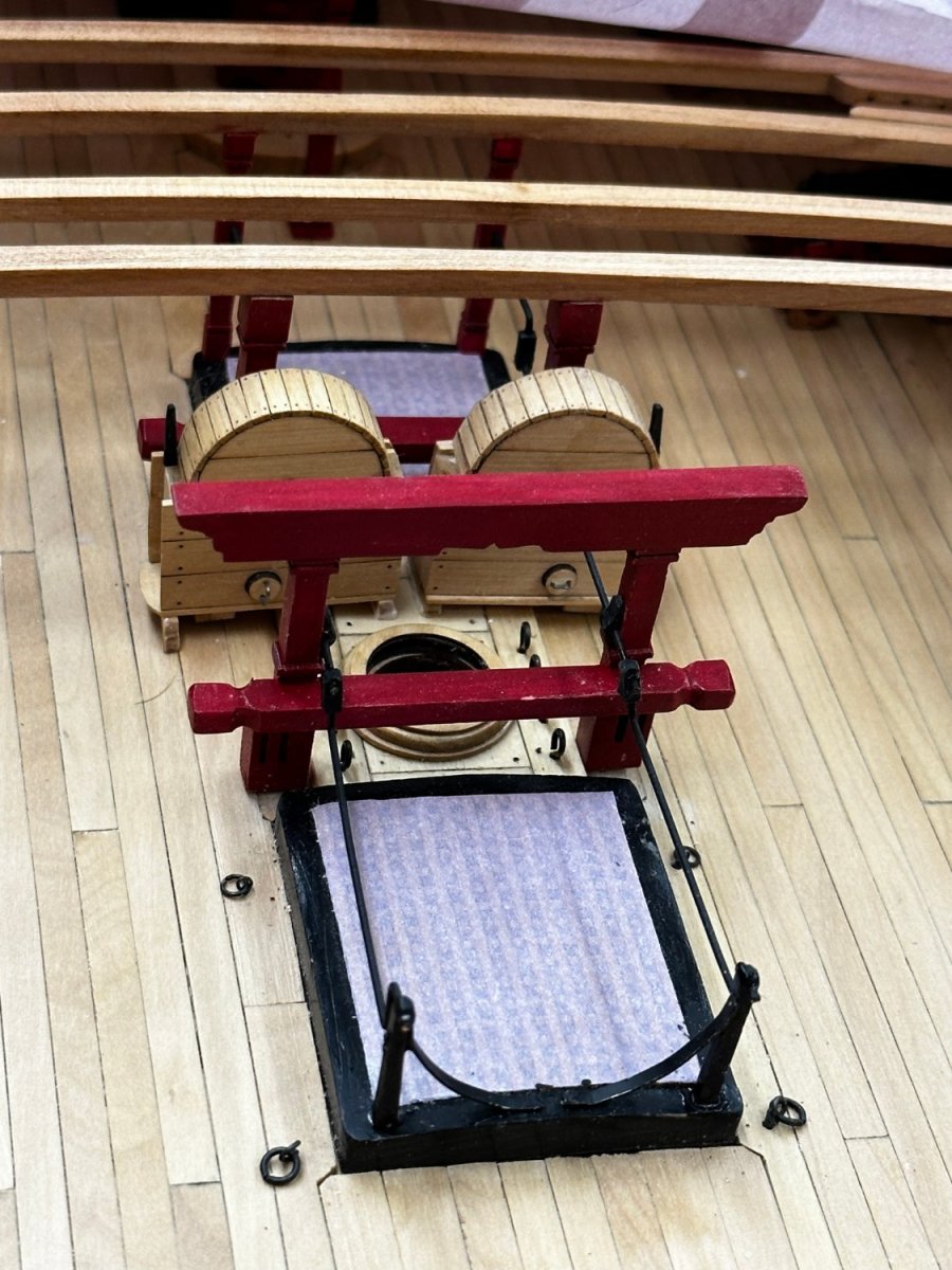
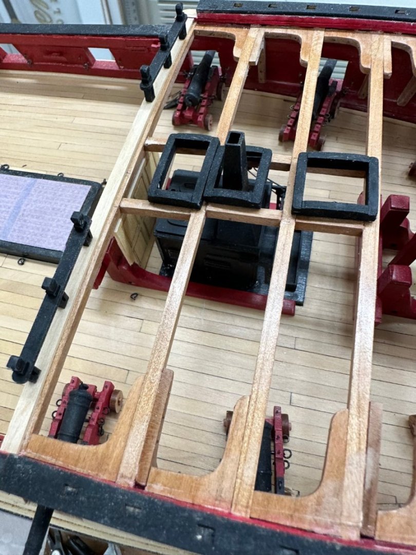
To "close the gap" on the fore mast partner I "grafted" a piece of the carrier sheet onto the partner and than sanded until I got it to fit. Yes there is a line where the additional piece was added but there will also be lines on both sides from the carlings are on each side of the mast partner so maybe it will not be too noticeable. With that in hand I built the built and painted the riding bits then dry fit everything, including the long ago built stove. Looks pretty good to me so on with cutting the carlings and gluing in the forward set of riding bitts.
- 389 replies
-
- 3
-
-
- winchelsea
- Syren Ship Model Company
- (and 1 more)
-
I apparently was a bit too zealous in "adjusting" the locations of the forward deck beams. When it came time to install the fore mast partner the provided piece is about 5/32" too short. The hole is extremely close to matching up with the coat in the gun deck when positioned as shown so I am assuming that it is the fourth beam back from the bow that is too far forward. I had to trim the lodging knee to accommodate the hanging knee at that beam so I would not have noticed the alignment problem until now. I am going to fabricate a replacement but am now worried about what other impacts this "misplacement" of the forward deck beams may have.
- 389 replies
-
- 1
-
-
- winchelsea
- Syren Ship Model Company
- (and 1 more)
-
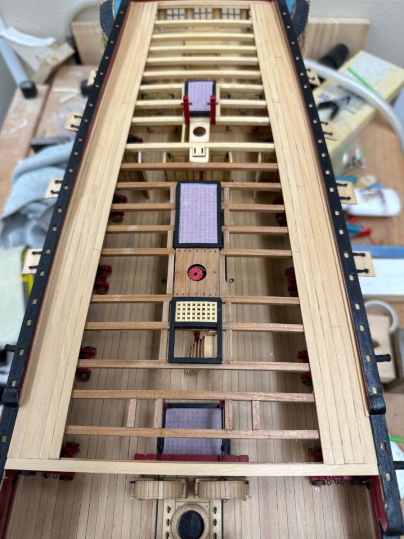
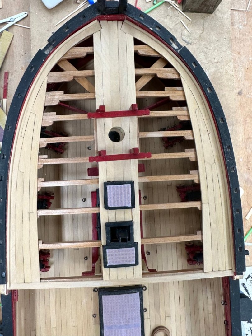
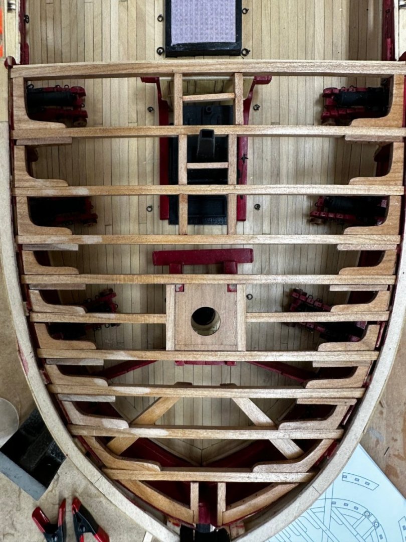
So I got the bowsprit step and the manger barriers assembled, painted and installed along with what I call deck beam F (fourth from the bow) and its hanging and lodging knees. No big issues just had to be careful to get the manger barriers locations consistent. Here are two views of them Next item are the remaining deck beams forward of "F" and the associated lodging and hanging knees. I got the next two completed and decided to "read ahead" and found that after the remaining deck beam is done the next thing is the cat tails which are mounted under the deck beams. According to the provided template the forward most deck beam is not required for the cat tail installation I decided to do that now and then add the last deck beam. Seems like it will be easier working the underside of the deck beams with as little "stuff" in the way as possible. So here is the forward deck beam installation as I begin the cat tail "saga".


- 389 replies
-
- 4
-
-
- winchelsea
- Syren Ship Model Company
- (and 1 more)
-
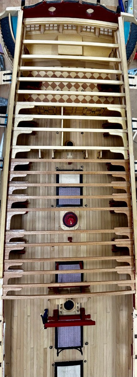
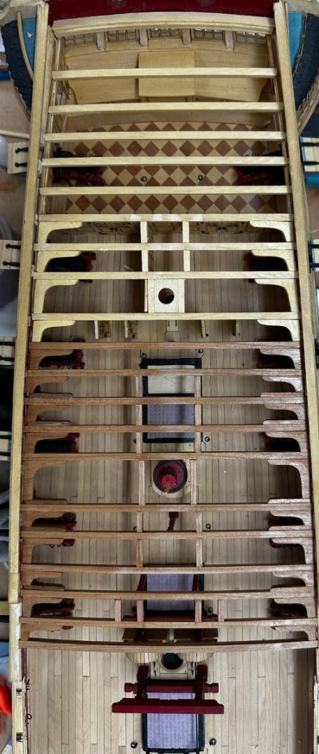
On to the bow! I adjusted the slots for the forward deck beams per the drawing. I would note that it is entirely possible to break off the entire section of the bulwark between two beams. This complicates making the adjustment somewhat. Don't ask me how I know. Anyway, I WoPed the beams and here they are waiting to be removed as we build the structures to go below. I also got all the klnees off the carrier sheet and marked the hanging ones and WoPed the entire bunch - at least on the edges and one side. I have to do the other side of the hanging knees tomorrow.
- 389 replies
-
- 4
-
-
- winchelsea
- Syren Ship Model Company
- (and 1 more)
-
I finished the elm tree pumps but have decided to not install them until later. the handles are too delicate and are just asking to get broken, especially when the waist work begins (Chapter 9 I think). Will reevaluate after I get done with Chapter 8 which starts NOW!

- 389 replies
-
- 5
-
-
- winchelsea
- Syren Ship Model Company
- (and 1 more)
-
Chain pump handles completed and installed (maybe some touch-up black paint necessary). Elm Tree pumps are under construction. Need to glue in the last two deck beams and install the last four knees. Getting close to the end of Chapter 7. 😀
- 389 replies
-
- 6
-
-
- winchelsea
- Syren Ship Model Company
- (and 1 more)
-
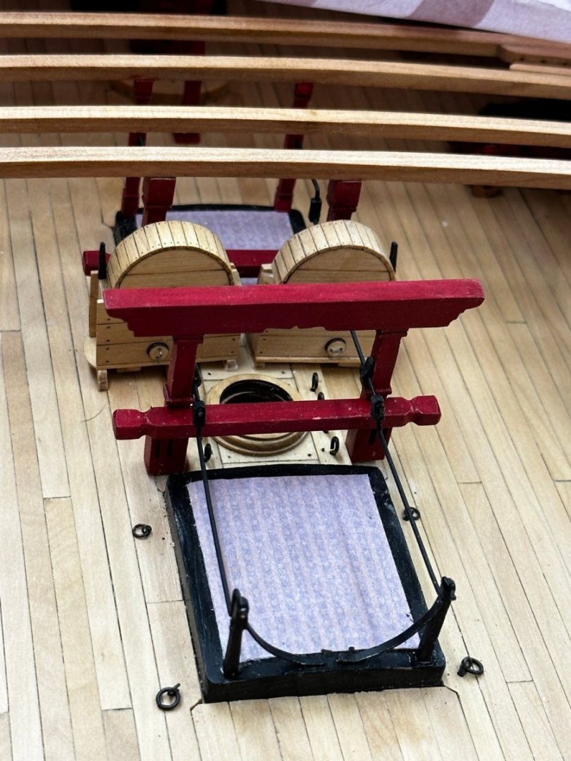
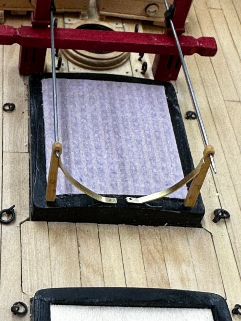
Test fit of the aft pump cranks before painting. As with the rhodings I had about a 50% success rate with the fittings although I used cherry instead of boxwood. Not sure it would have been easier with boxwood because that is what I used for the rhodings. In "real life" the alignment between the two sets looks better than in the photo. Trying to get my iPhone in there and vertical is a challenge up to which I am not.
- 389 replies
-
- 6
-
-
- winchelsea
- Syren Ship Model Company
- (and 1 more)
-
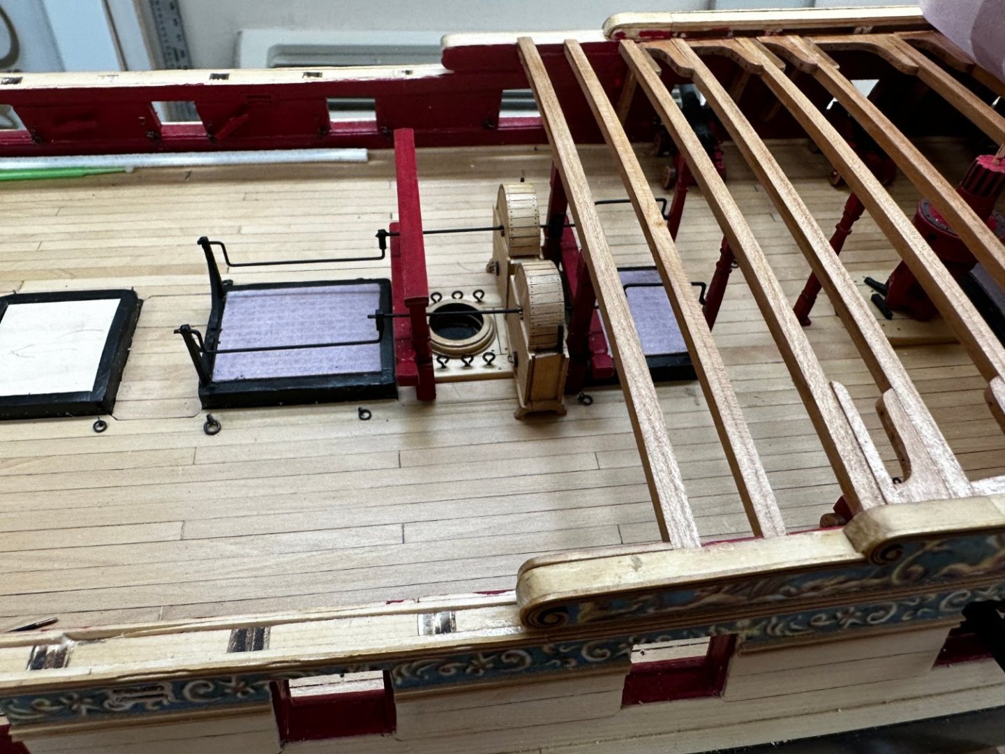
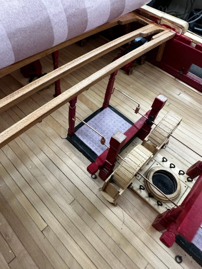
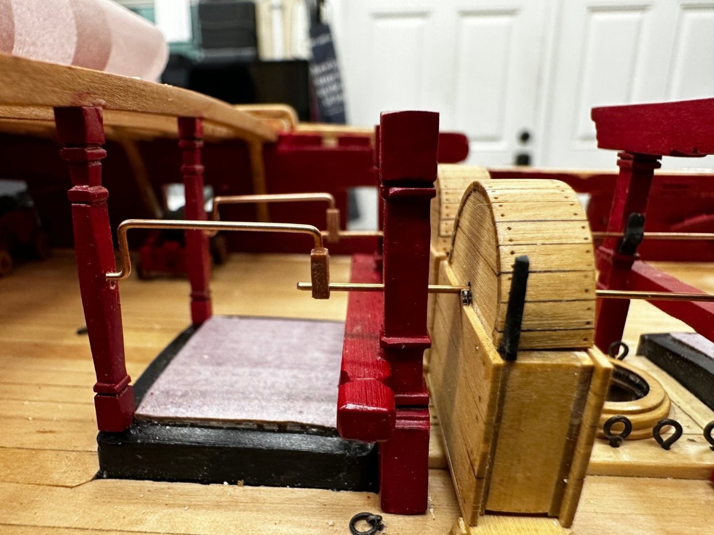
Dry fit of forward hand crank stanchions - before painting. Stanchions are pinned to coaming with .025" piano wire with point on end. I drilled a hole in the brass "support" to fix it to the coaming. They are attached to the stanchion with thick CA so I am hoping having them anchored to the coaming too will prevent them coming off during the crank fitting.
- 389 replies
-
- 2
-
-
- winchelsea
- Syren Ship Model Company
- (and 1 more)
-
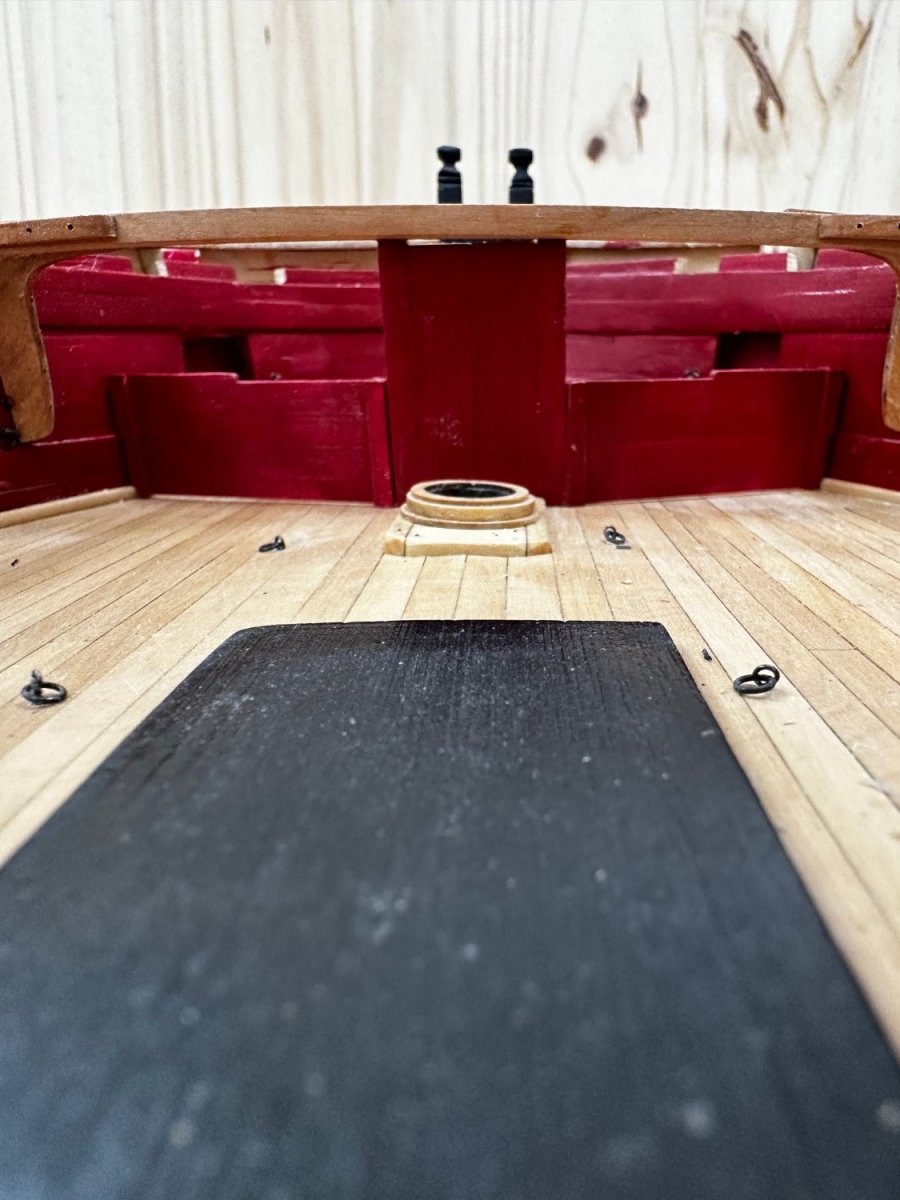
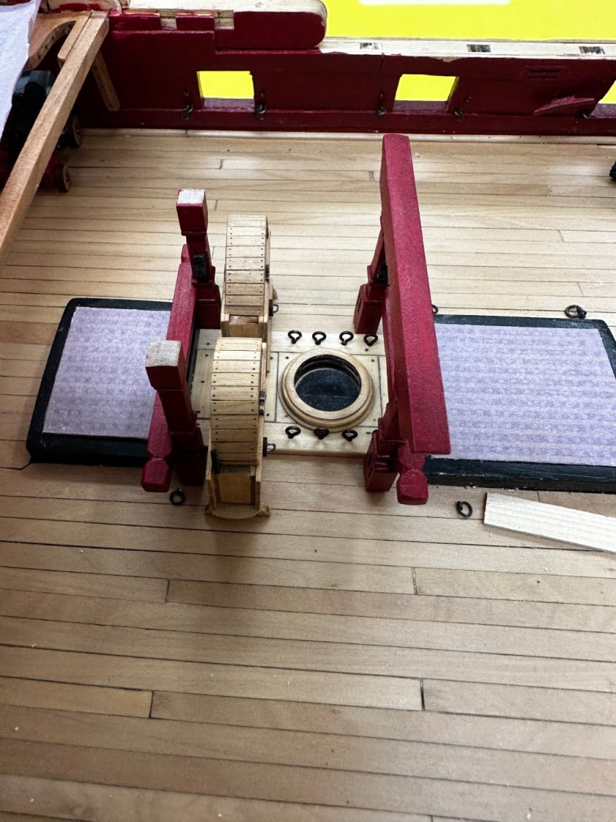
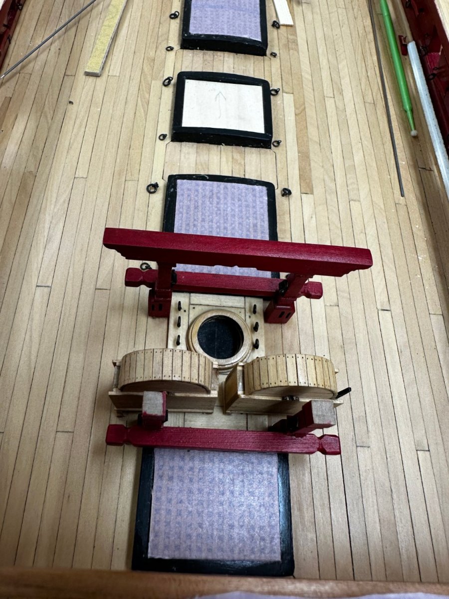
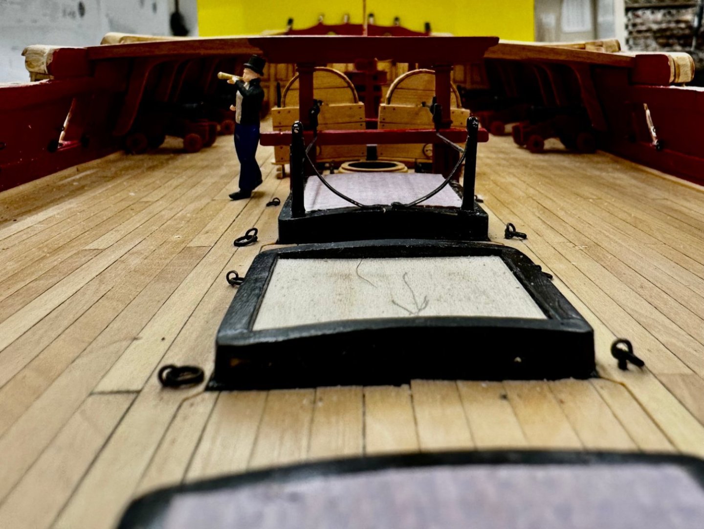
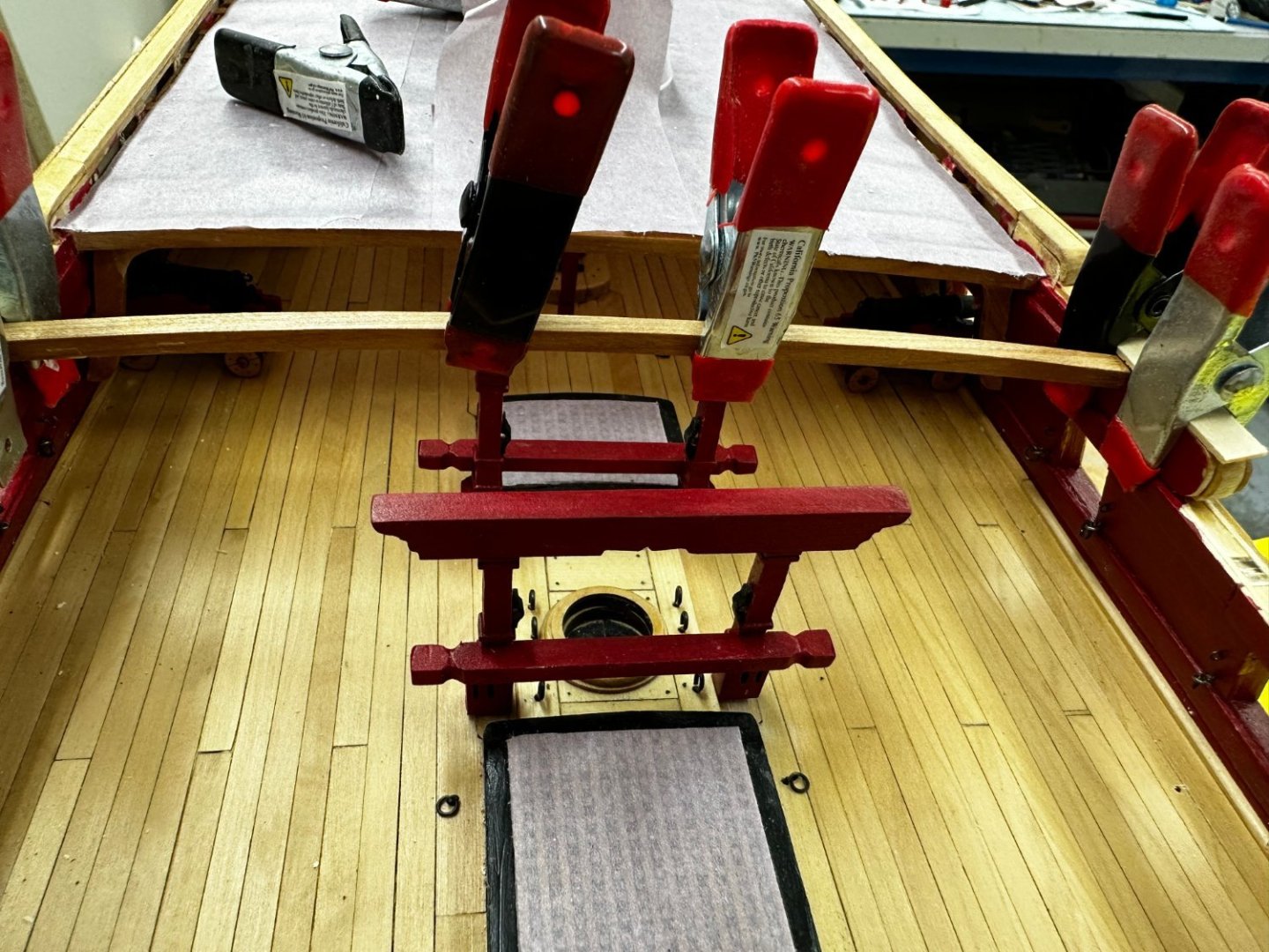
Gallows, Jeer Bitts and Chain Pumps have been installed and aligned. Now for the two stanchions on the aft end of the companionway coaming.


- 389 replies
-
- 3
-
-
- winchelsea
- Syren Ship Model Company
- (and 1 more)
-
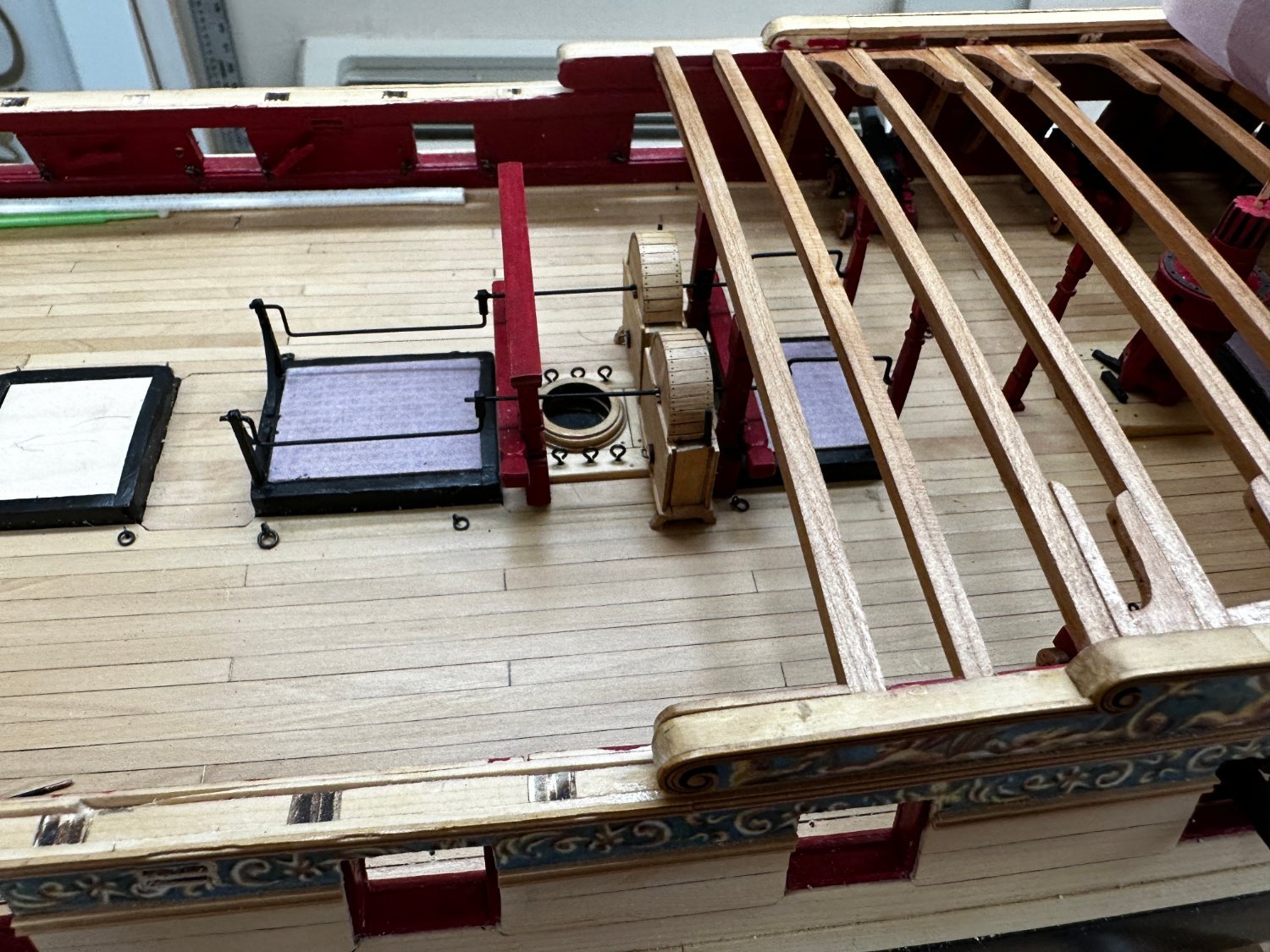
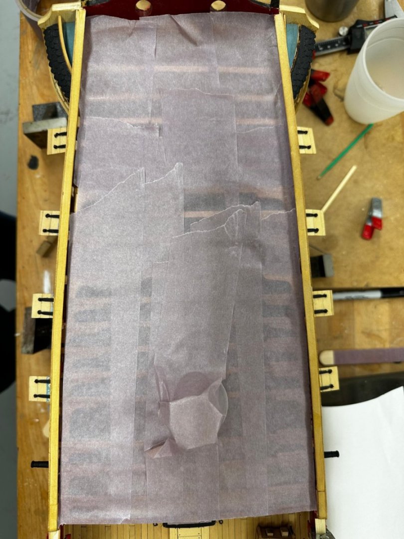
I was pleasantly surprised that the gallows and jeer bits lined up without any drama. I glued the gallows Rhodings in place and then the gallows onto the deck. Once that dried I used the same alligator clips to hold the Rhodings on the jeer bitts and ran the "test wire" through the gallows, chain pump and jeer bits. The Rhodings worked exactly where I placed them the first time. Now I have glued the jeer bitts in, but only to deck for now. The Breast beam is still held in place by clamps. After I get the other two stanchions in place the Breast beam will be glued in place. Speaking of the Breast beam, I am toying with the idea of using boxwood for the "fancy molding" rather than cherry. I With all the knees completed up to deck beam #3, I decided to cover that area to keep any debris from collecting where it will be hard to remove. I also taped a mixing cup over the capstan shaft - I have almost snagged something on that any number of times. I wish I could think of a way to protect the gun port doors. With the cannon in place they have to be open but I think it only a matter of time until something catches on one with predictable consequences.
- 389 replies
-
- 1
-
-
- winchelsea
- Syren Ship Model Company
- (and 1 more)