HOLIDAY DONATION DRIVE - SUPPORT MSW - DO YOUR PART TO KEEP THIS GREAT FORUM GOING! (Only 13 donations so far - C'mon guys!)
×


cdrusn89
-
Posts
1,915 -
Joined
-
Last visited
Content Type
Profiles
Forums
Gallery
Events
Everything posted by cdrusn89
-
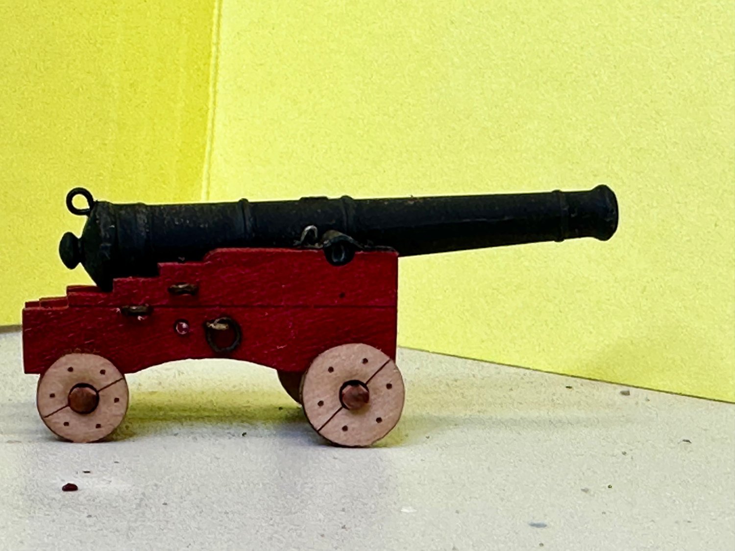
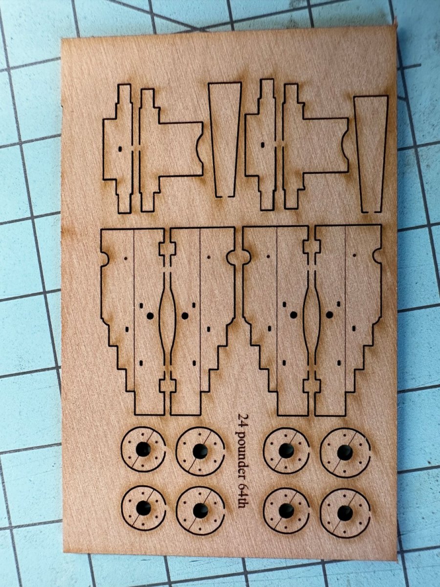
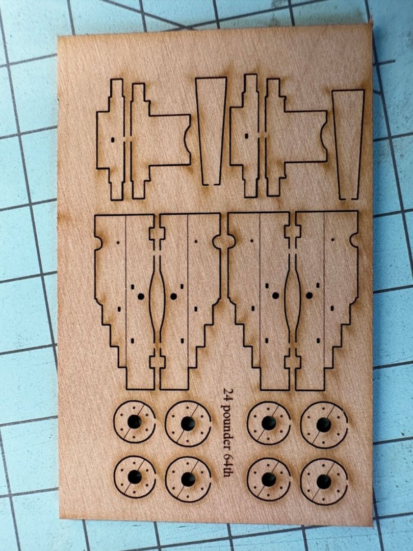
 The first cannon completed. I am using the 24 pounder carriages and guns from Vanguard. They are supposed to be 1/64th scale so I used the next size up from what Winnie carried. They are within a few hundredths of the size that Chuck sells (see my 4/21/23 post above). I chose the Vanguard cannon/carriages mostly because the carriages have only five pieces and after I built a little jig they went together very quickly. Here is what the carriage looks like before assembly I also like the wheel design. I have my doubts about whether they are historically correct but since the armament is not the principal feature of the model I choose the path of least resistance (again) - no cannon rigging and an easier carriage assembly. So here is the first assembled carriage. I added the ring on top of the barrel in case I decided to rig the breeching line but in the end decided no rigging. I decided to leave the laser char on the wheels since they would certainly not be clean very long. I did sand the char off where the wheel attached to the carrier sheet. I plan to glue the wheels on with that spot at the bottom to help keep them glued down to the deck, when that time comes. Only 25 more to go.....
- 389 replies
-
- 6
-

-
- winchelsea
- Syren Ship Model Company
- (and 1 more)
-
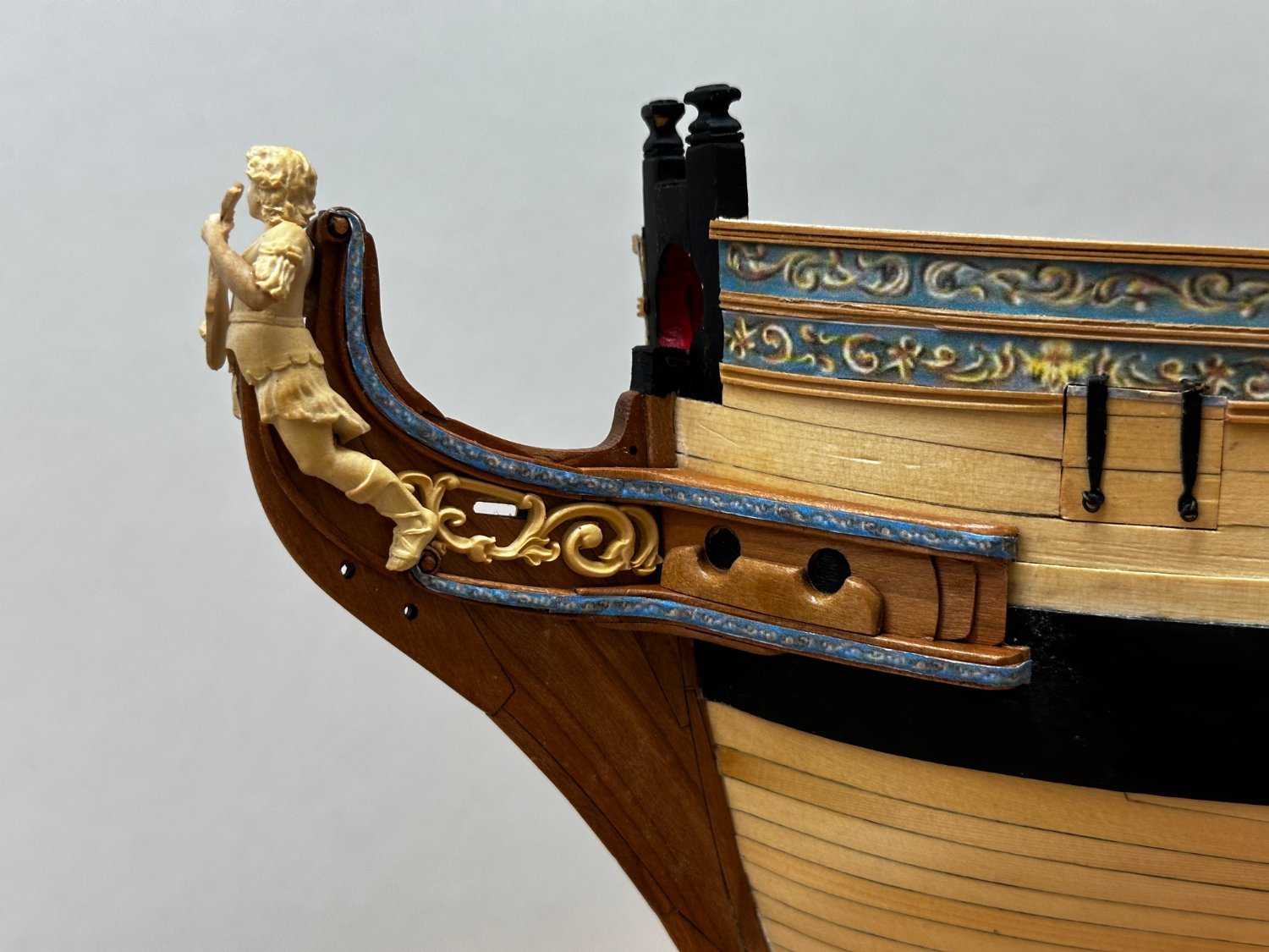
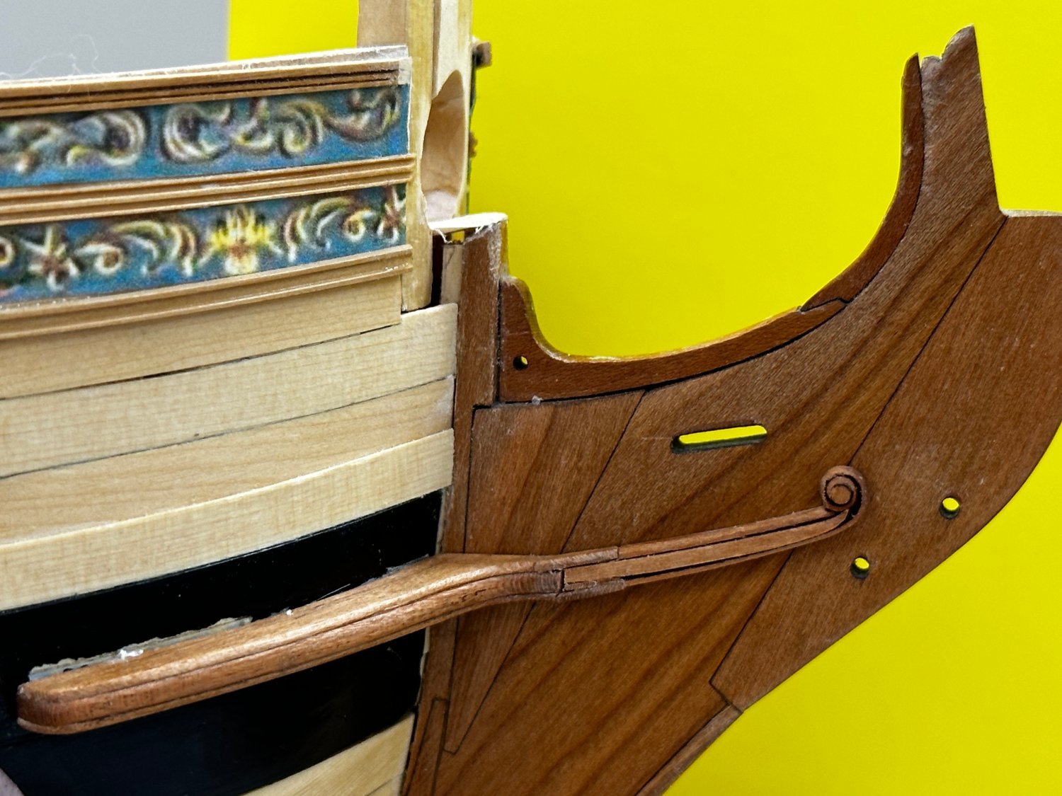
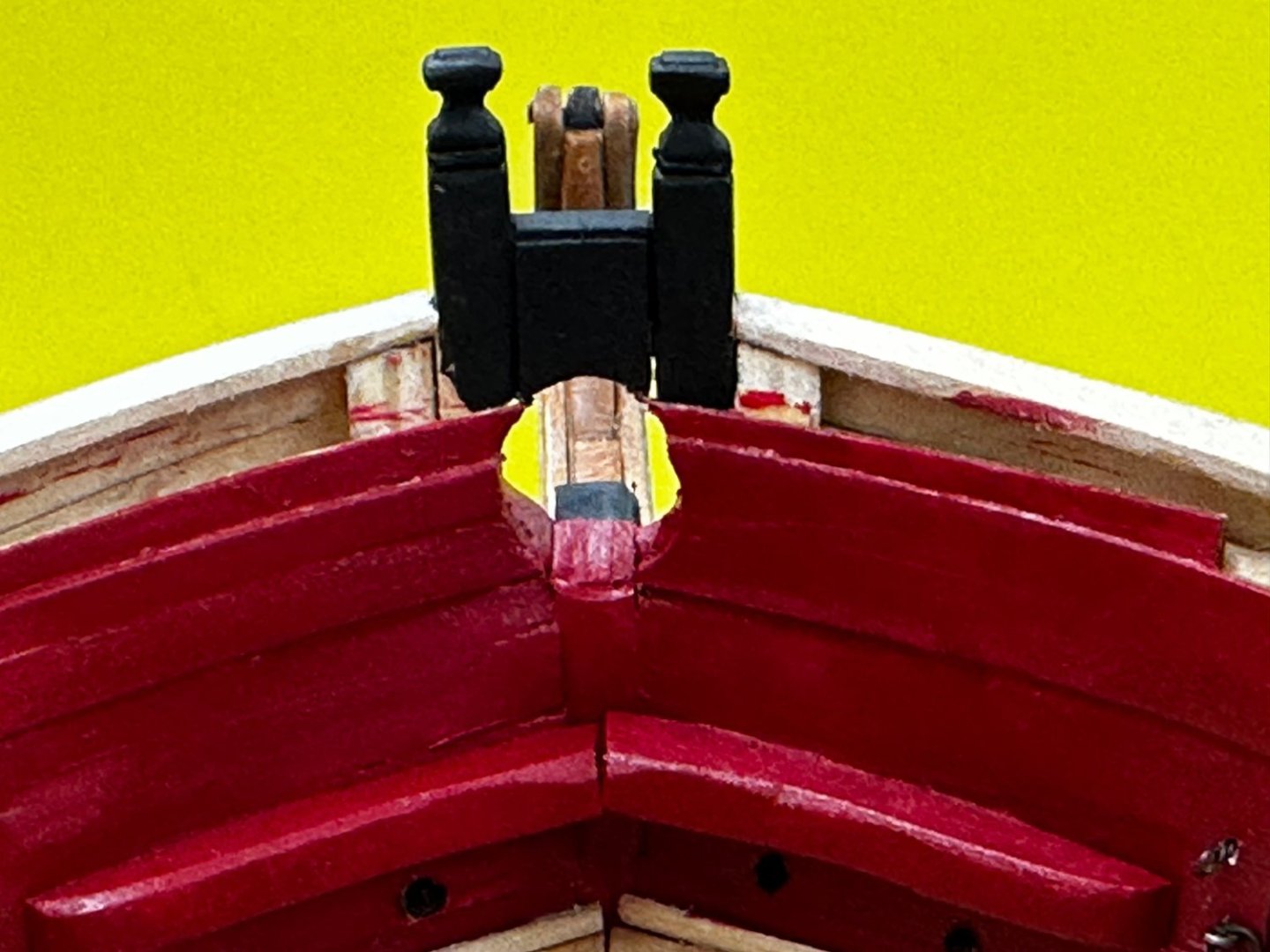
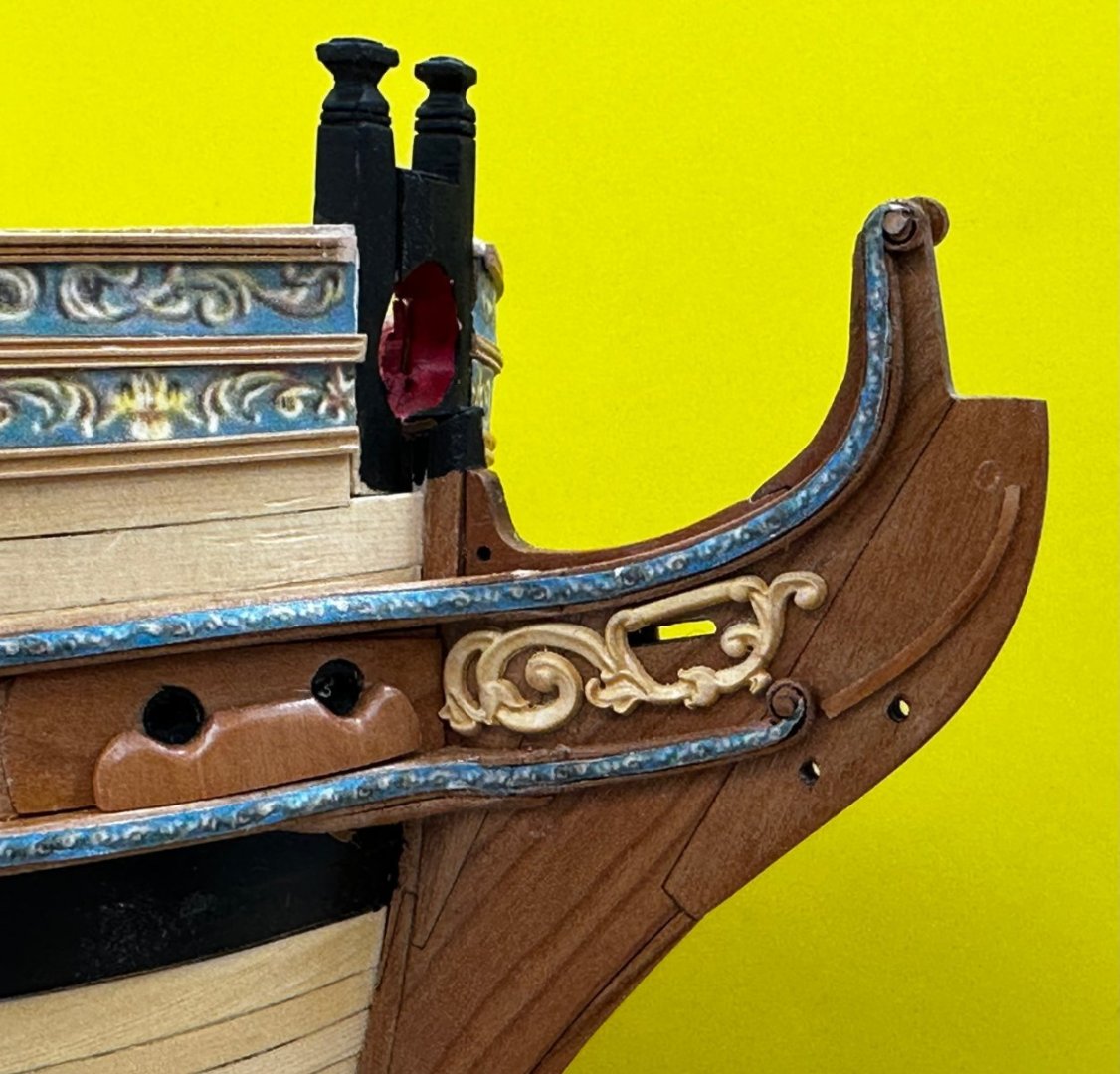
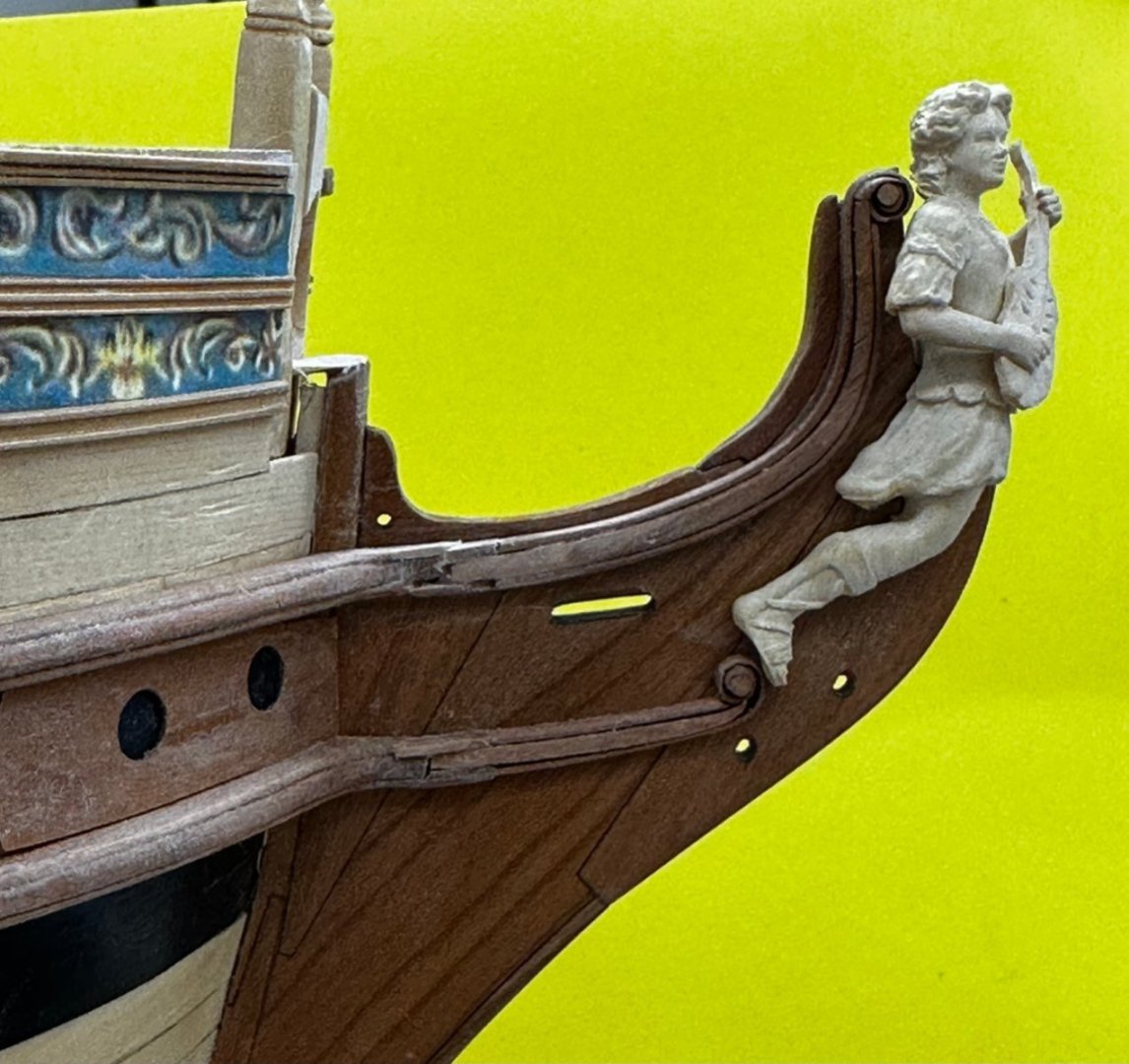
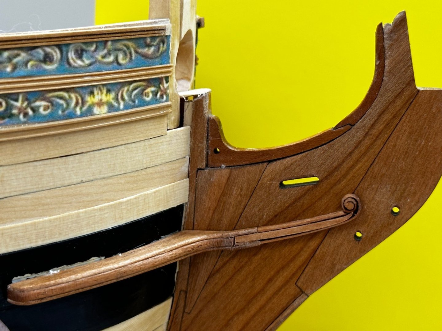
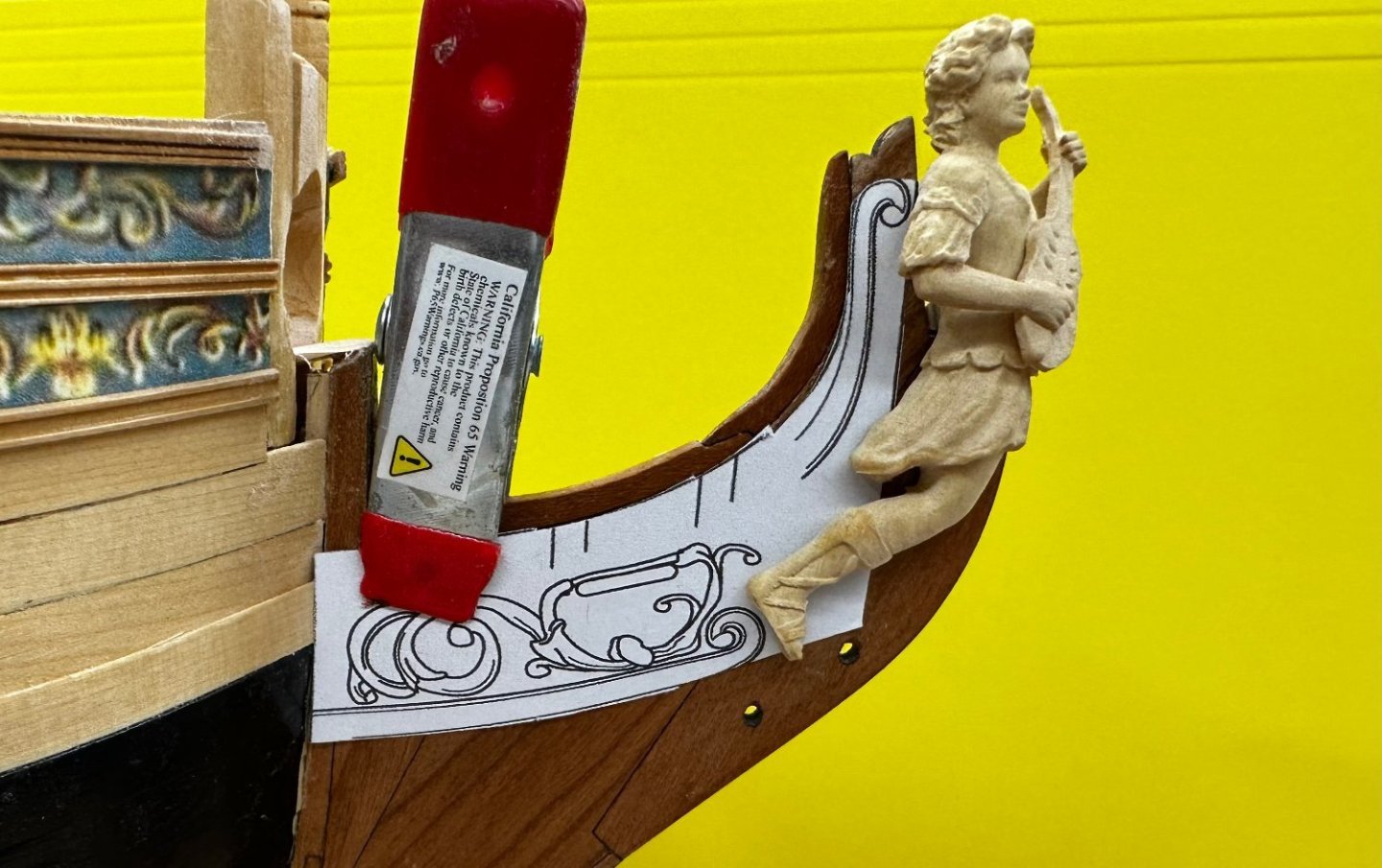
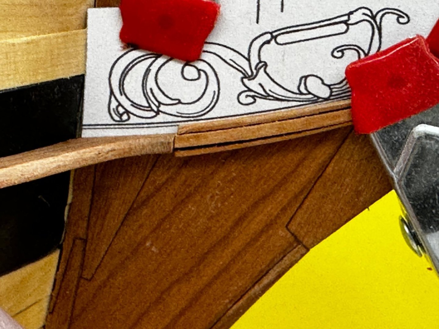
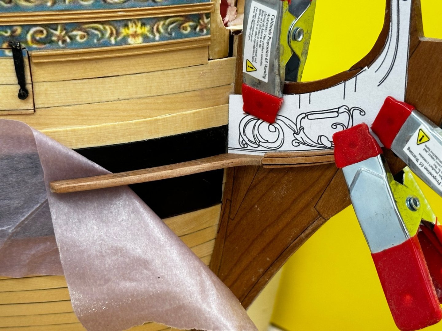
Back from 32 days on the Jewel of the Seas. Won't do that again anytime soon. 32 days is just too long to be gone. So back to the Winnie. I decided to not paint the stem flat black as shown in the monograph. I am going to leave the stem the natural cherry color. I did paint the bollard timbers and the hole for the bowsprit black and while I was at it touched up the red paint in that area. I also added the hawse holes on the inside and the timbers above them. as mentioned in the monograph it will be next to impossible to see the inner hawse holes so I just drilled them deep enough so I could get them the necessary diameter. Here is a view of the bow from inside the hull. You can just barely see the inner hawse holes. I added the bolster, the decorative piece on the cheeks and the decorative molding in front of the figurehead legs so I think this just about completes Chapter Five in this area. Here is the starboard side. And here is the port side with the figurehead in place although I have not put any finish on it yet. I am building a new rudder out of Cherry this time. I did not like to look of the cedar rudder with the stem and keel in Cherry. I am not sure what I was thinking when I built the cedar one. Anyway, that and building the cannon it what is on the agenda for then next "little bit".

- 389 replies
-
- 8
-
-
- winchelsea
- Syren Ship Model Company
- (and 1 more)
-
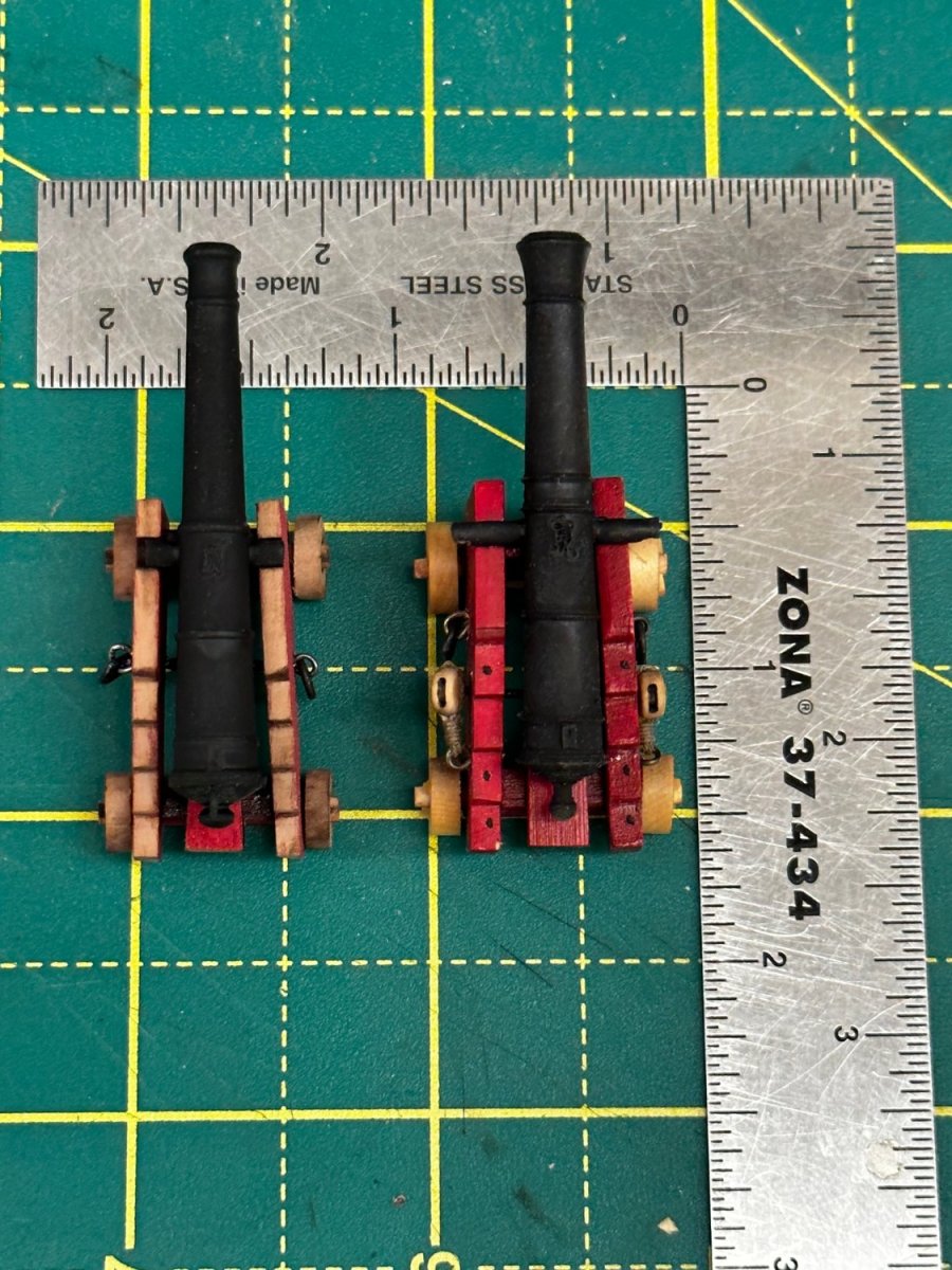
Glenn, - they are 1/64 scale but their 24 pounders are almost exactly the same size as Chuck's largest carriage. And their cannon are just a hair longer than Chuck's 1 29/64" but are not as "thick". Chuck's on the right below

- 389 replies
-
- 4
-
-
- winchelsea
- Syren Ship Model Company
- (and 1 more)
-
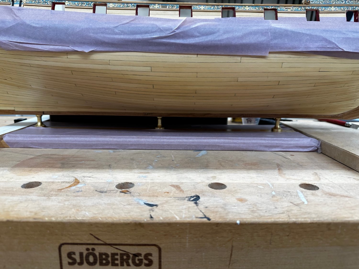
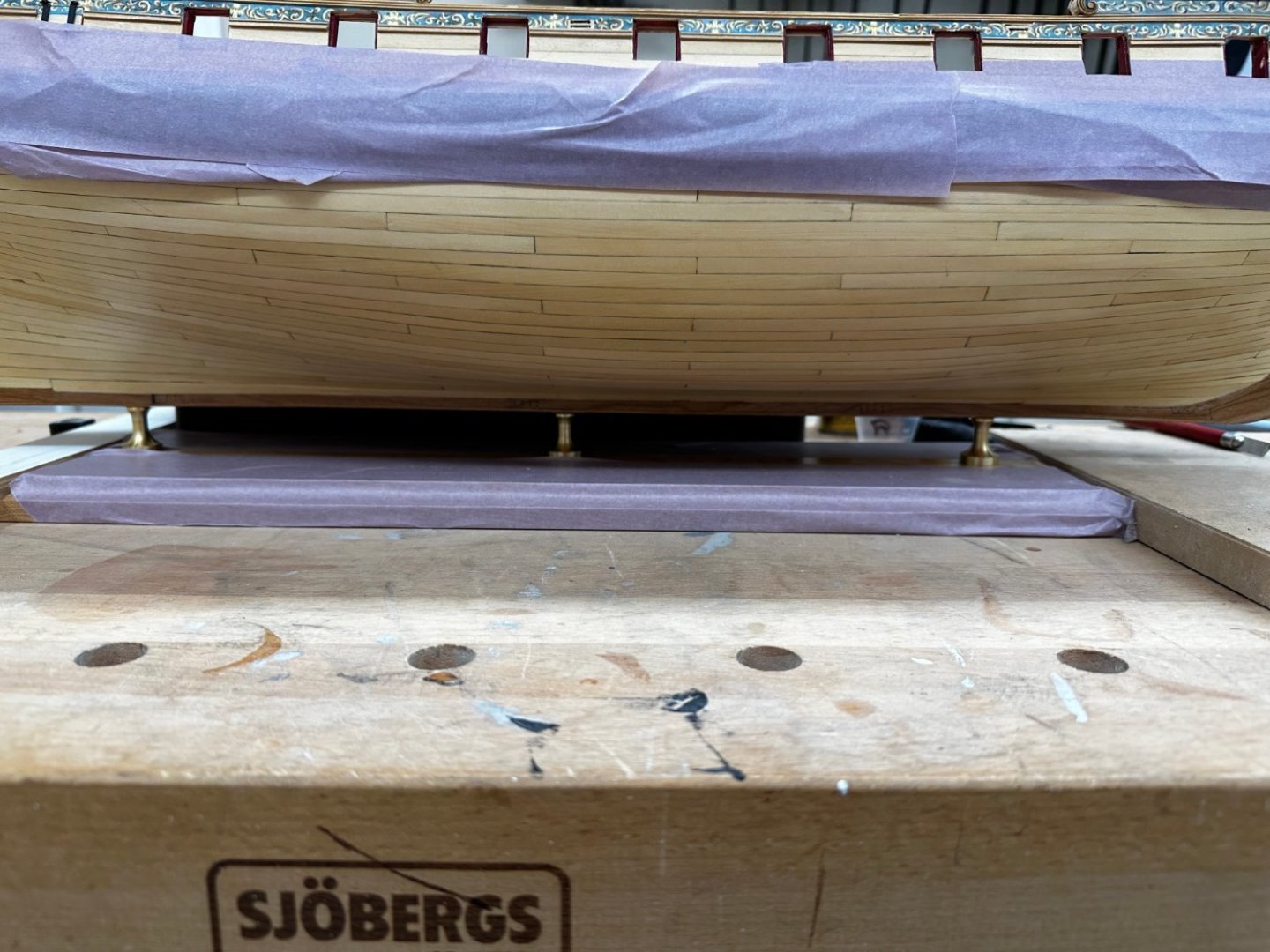
Last day at "work" on Winnie until after Memorial Day. One thing I have gotten accomplished is moving Winnie out of the "graving dock" and onto what I assume is her final resting place. I used the flat top stand-offs because I could not find any of the slotted variety with the necessary 1/4" wide slot. You can get 3/16" all day long and I do not have the tools (hard to imagine I know) for removing 1/16" of brass without making a mess of things. I thought about making some wooden stand-offs but without a lathe that might prove as difficult as trying to widen the 3/16" brass ones. If anyone has a source for brass stand-offs with a 1/4" wide slot I would appreciate the info. The masking tape is there to keep the five coats of WoP in good condition as construction continues "above". Trying to get Chapter 5 done so I can start on the wonderful" gun carriage assembly task. Looking to that I have ordered gun carriages/cannon (the 1/64 scale 24 pounders) from Vanguard as I find the carriages easier to assemble (fewer parts) and the wheels have more detail than the plain ones you find in most others. The cannon are resin and very similar to others except these come with the barrel opening pre-drilled. I had a terrible time getting others drilled out consistently. Anyway they should be here by the time I get back. One other decision made is to follow Chuck's lead and leave the guns un-rigged. I have rigged the guns on my previous models (the armed ones anyway) and believe that doing so here is certainly within my capabilities, it is just a great deal of effort that I think takes away somewhat from the "Admiralty Model" emphasis on the structure and layout of the vessel rather than trying to provide every possible detail. As for Chapter 5 I got the new set of "pieces" yesterday and got the upper cheek and hair bracket installed per my liking but then thought better of the lower cheek/bracket I decided I had to redo it as well. So here are the port side cheeks/hair brackets - one coat of WoP (not yet dry) on the portions on the hull. The hair brackets have a previous coat. Will get another coat on tonight and maybe in the morning (we are supposed to be at Port Everglades at 1130) I can get the frieze on. Bolster for the port side still needs to be fabricated but will have to wait until "later".
- 389 replies
-
- 4
-
-
- winchelsea
- Syren Ship Model Company
- (and 1 more)
-
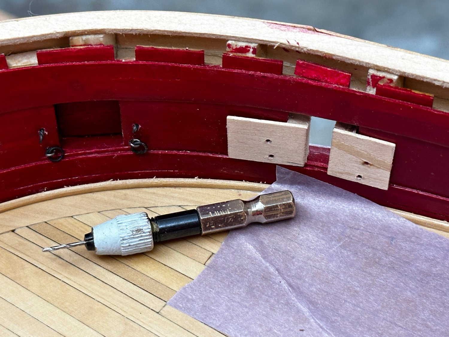
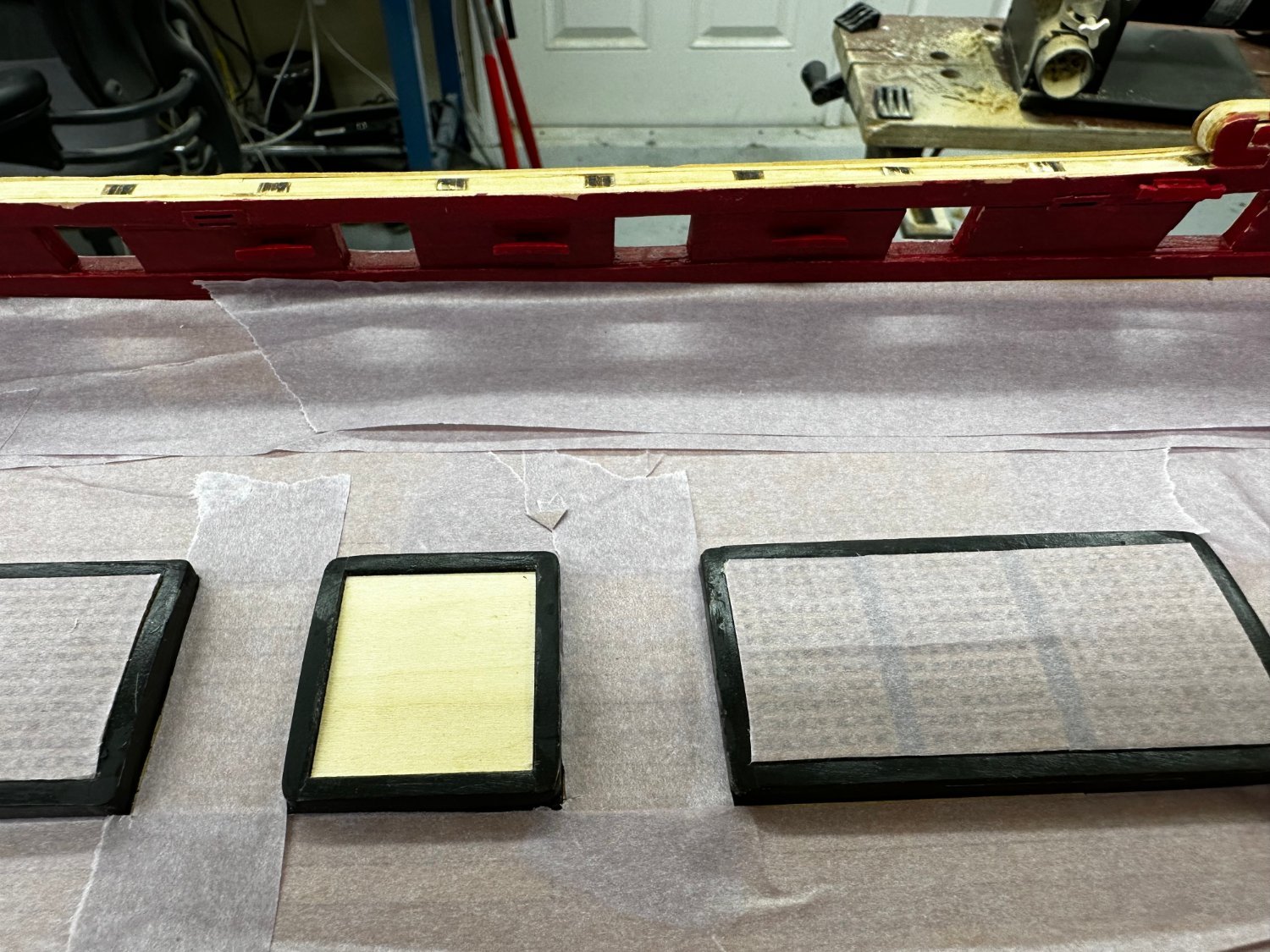
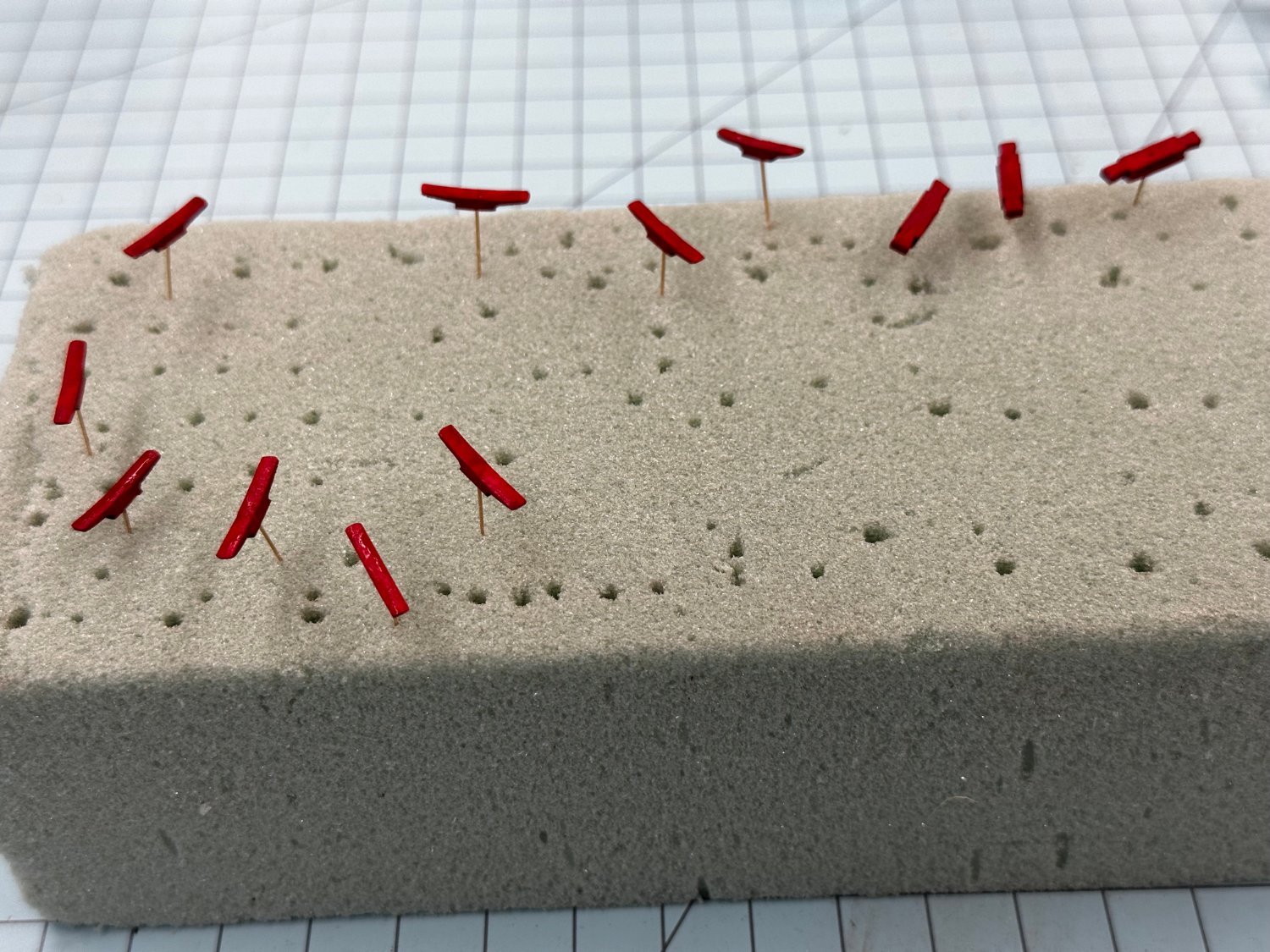
I so thoroughly messed up the port side cheeks that I ordered a new set of material that is due here tomorrow. So with no cheeks to work on I decided to drill the holes for the gun tackle. I built two templates that fit against the bottom and one side each of the gun port. I used the plans to locate where the tackle eyebolts should be relative to the bottom and side of the gun ports and as best I can tell the measurements are the same for every port, even though the distance from the deck to the port sill varies (not much but some) from port to port. Then I used two of the Model Expo foam cradles to carefully lay the Winnie on her side to mark and drill the holes. I used a cordless chuck from a cordless screwdriver to hold the drill bit with just enough exposed so I could not drill through the bulwark. In the picture below are the two templates, the chuck and drill and the eyebolts in place at gun ports 1 and 2. Hopefully more cheeks tomorrow. In the meantime I am going to work on the guns/carriages since they will be "coming up next".

- 389 replies
-
- 3
-
-
- winchelsea
- Syren Ship Model Company
- (and 1 more)
-
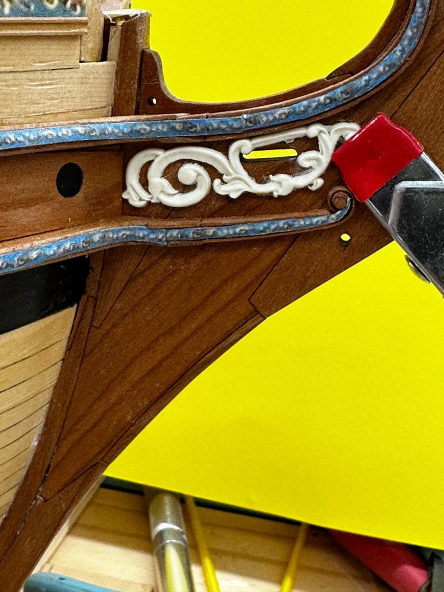
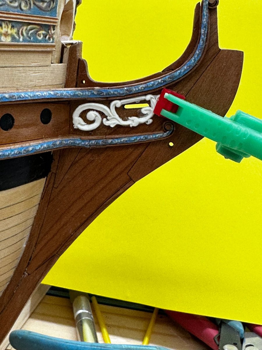
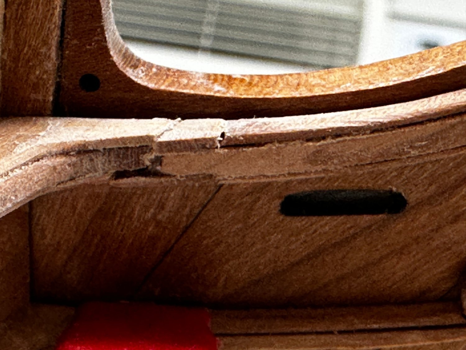
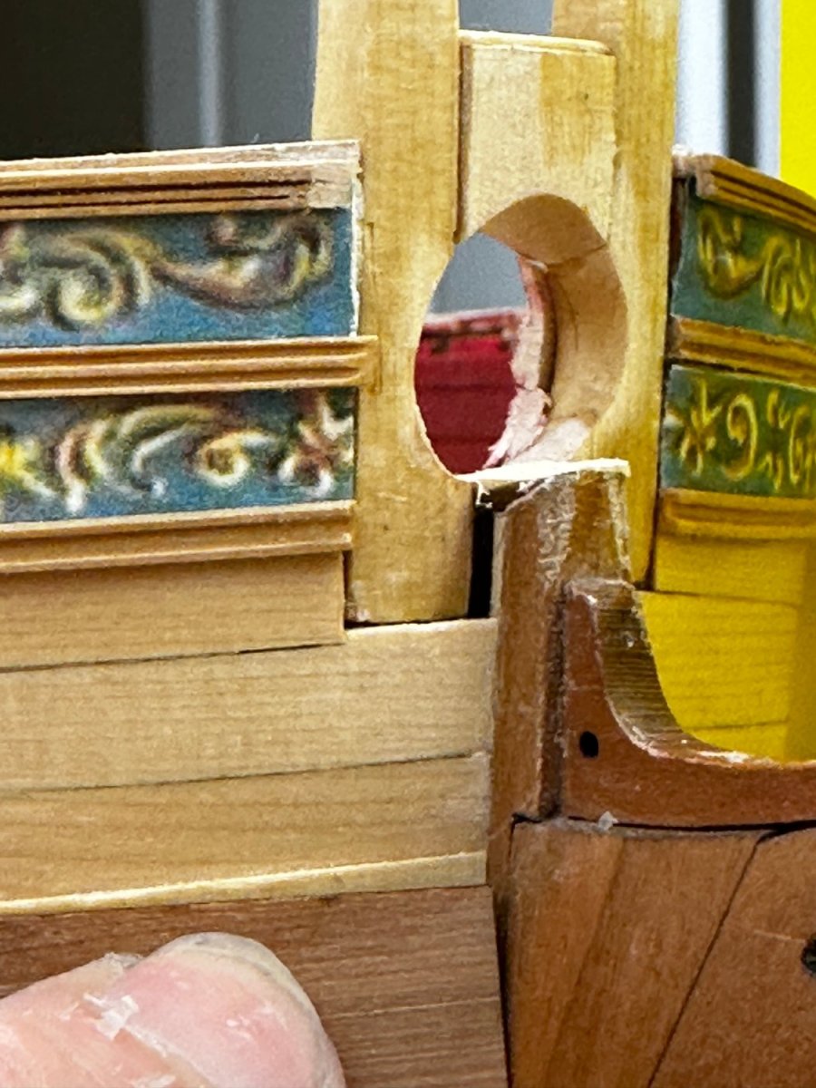
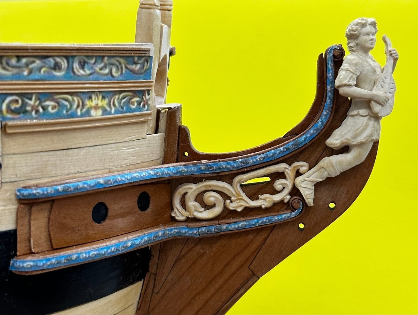
I have completed the starboard side hair brackets/cheeks. The decorative piece seems to get in the way of the slot for the bow spirit gammoning. I am using the boxwood figures which I got from China. By my measurement the boxwood decoration is about 1/16" longer than the resin one from Chuck. Here is the resin one in place of the boxwood one. Better but still not completely clearing the gammoning slot. I cut off the aft most curlicue and now it appears to clear the slot with some judicious "wiggling". Since the gammoning has to clear the hair bracket I would think that as long as you can see through the slot that it would be "okay". I am not sure I am ready to do that with the boxwood decoration - I will see what happens on the port side; something very similar I would hope.


- 389 replies
-
- 5
-
-
- winchelsea
- Syren Ship Model Company
- (and 1 more)
-
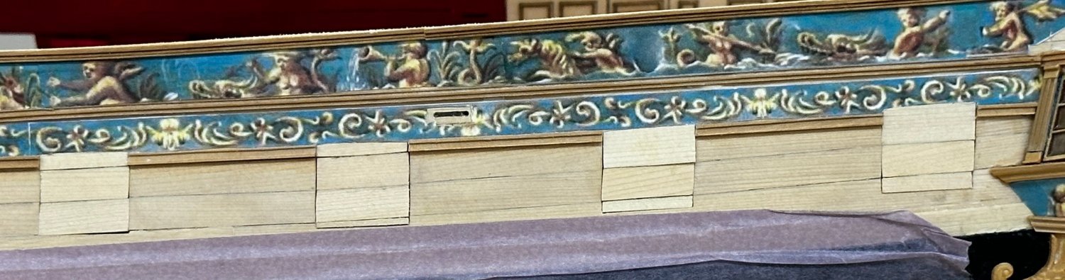
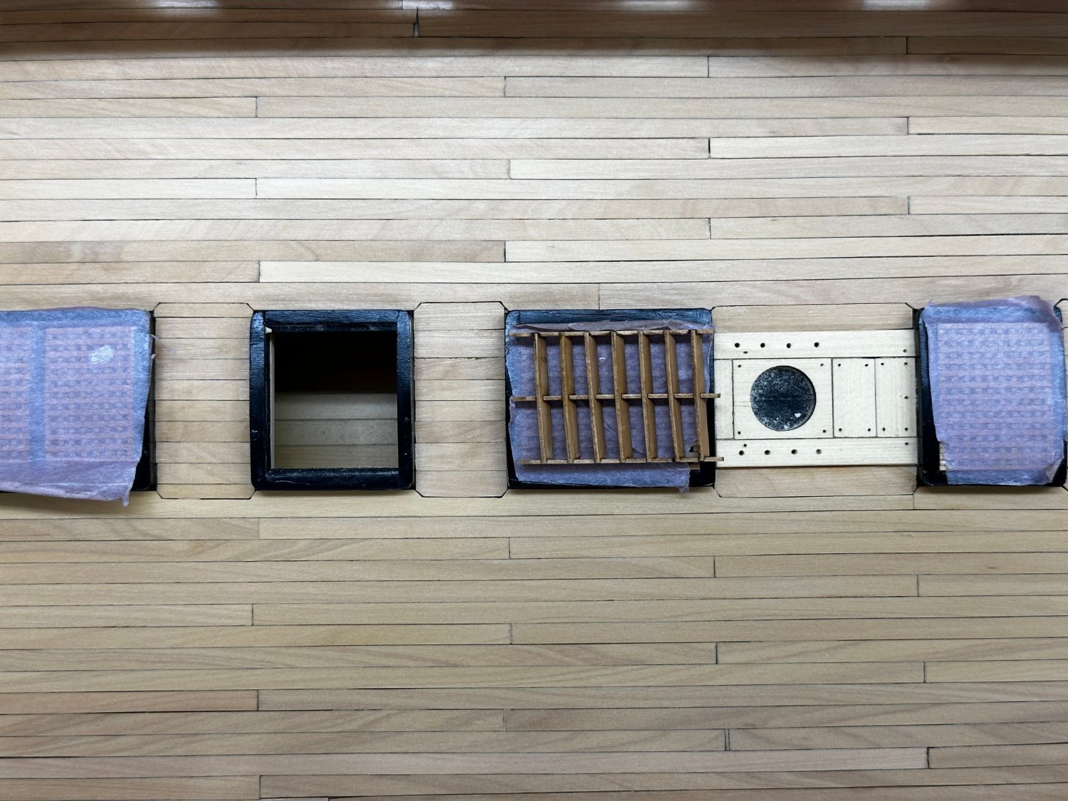
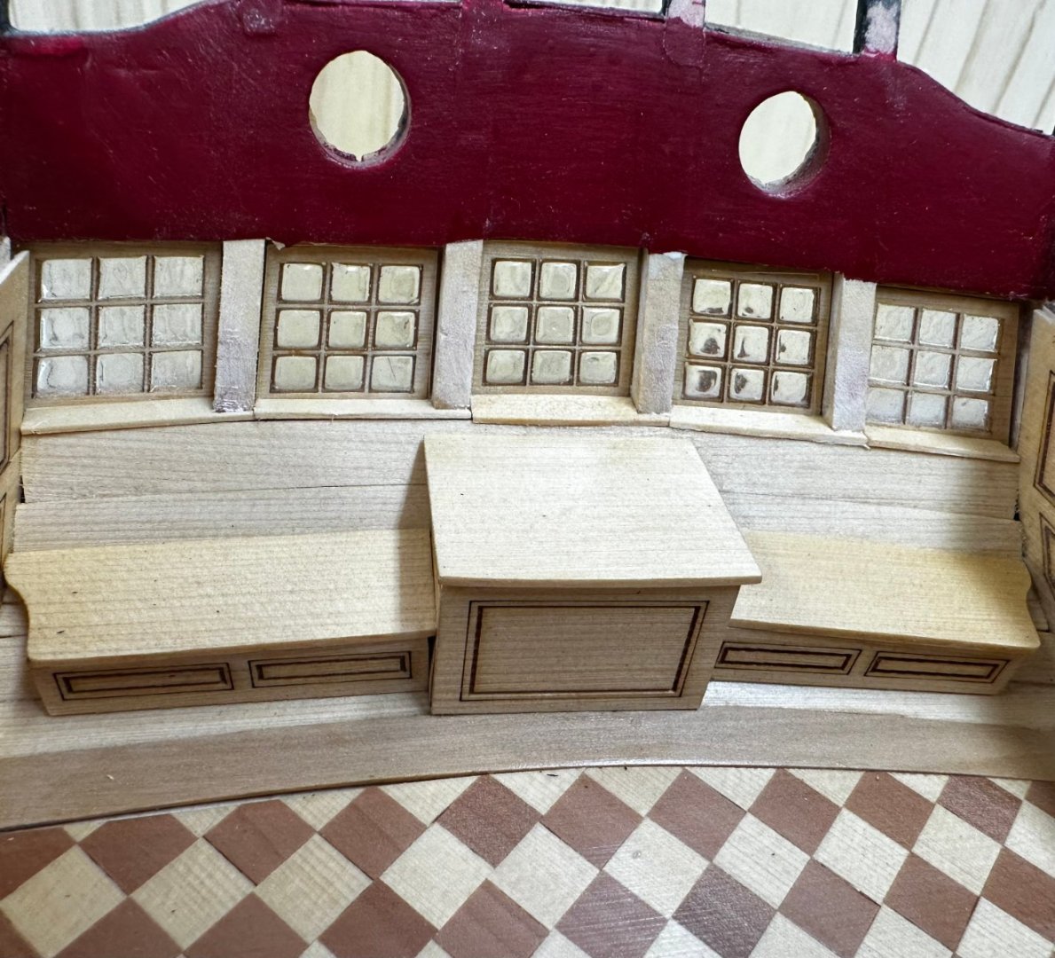
I am trying to get Chapter 5 completed before Saturday as Friday is my last day "working" until after Memorial Day. So I added the eyebolts and split rings on the deck. And the sills under the aft windows - one coat of WoP, may have to do it again. I put the windows in before I put the decking on and I used both the acetate and Micro Crystal Clear for the windows. The acetate is on the inside of the windows and the Micro Crystal Clear is on the outside. Although the windows are not really clear they look better in real life than in the picture. I am pretty sure they did not have perfectly clear, flat glass like we are have back in the late 1700's. And I doubt the Royal Navy would have paid extra for really clear glass since it was mostly for lighting. If you want to see what is outside GO ON DECK! would be my guess at the RN's position. Now for the hair brackets and cheeks (starboard side). I ran into more than a little difficulties mounting both the cheeks hair brackets. I tried to use a joint that did not have all three pieces of each item joining at the same place. Unfortunately that meant using the very fragile 1/32" pieces on the top and bottom extending beyond the center piece on the cheek. Turns out that was a pretty bad idea as both those small pieces broke off on the upper and one on the lower while trying to get everything in place. Here is my "repair" job on the upper cheek. No WoP on the repair yet. Pretty ugly - However I think much of this is made much less visible as the rest of the bow details are added. At least that is my hope. On the port side I will make the joint all in one place. Hopefully it will look better than on this side. Here is what the starboard side looks like now - I have the bolster ready for WoP and am unsure about actually drilling the hawse holes.


- 389 replies
-
- 3
-
-
- winchelsea
- Syren Ship Model Company
- (and 1 more)
-
Glenn - I have nothing to do but travel and work on the Winnie. And yours looks considerably better than mine. I attribute that to my advancing age and increasing lack of patience. And by the way I built the hull structure twice.
- 389 replies
-
- 2
-
-
- winchelsea
- Syren Ship Model Company
- (and 1 more)
-
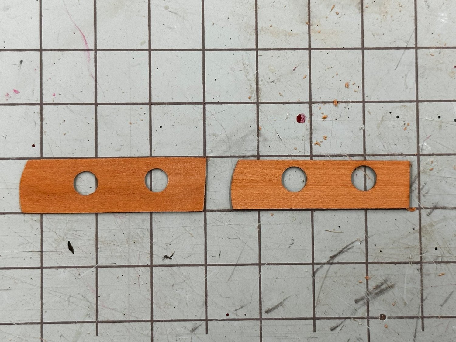
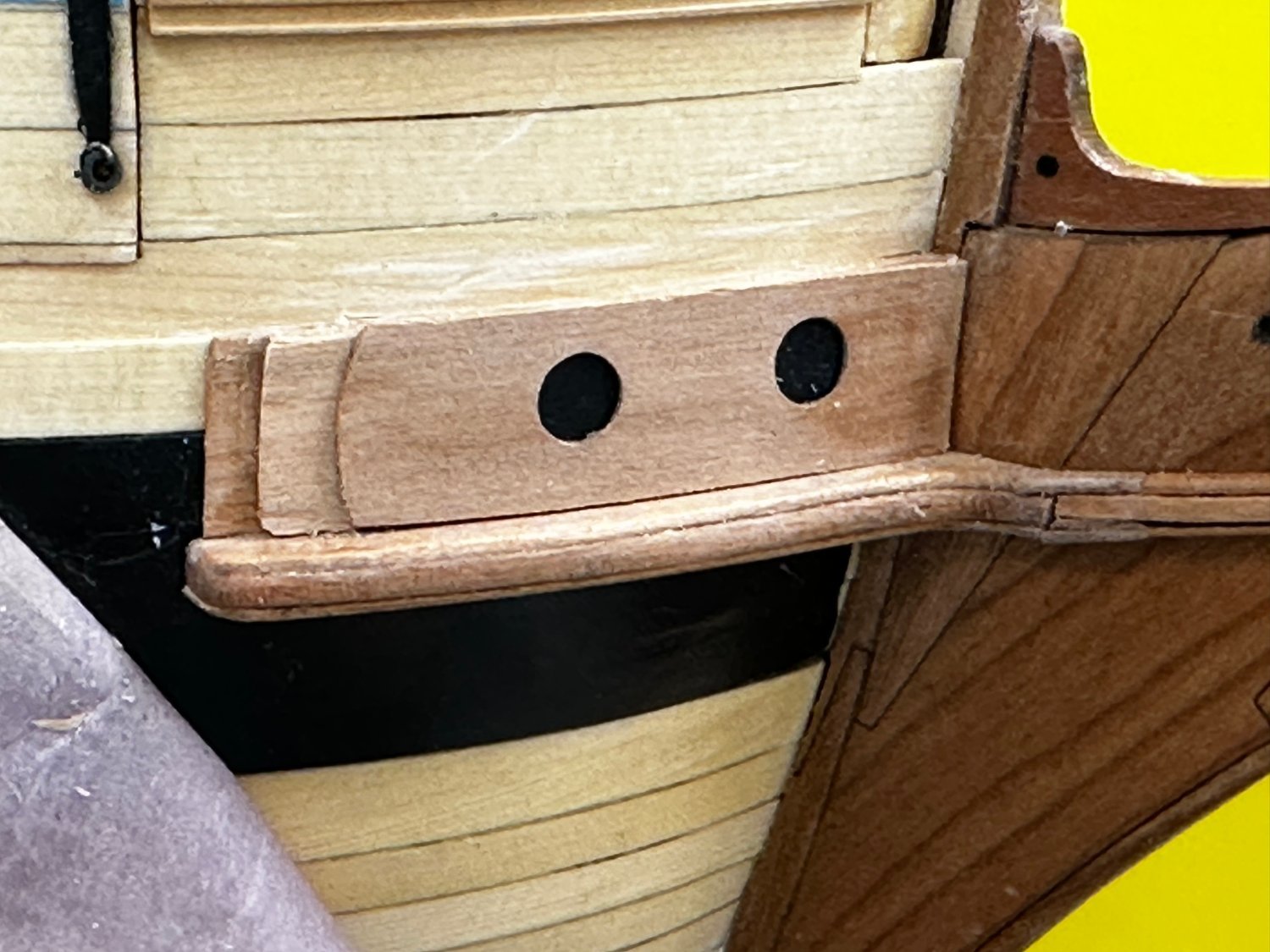
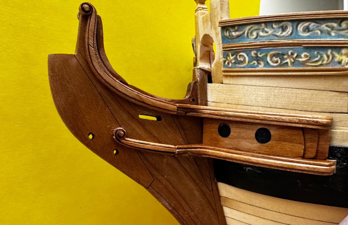
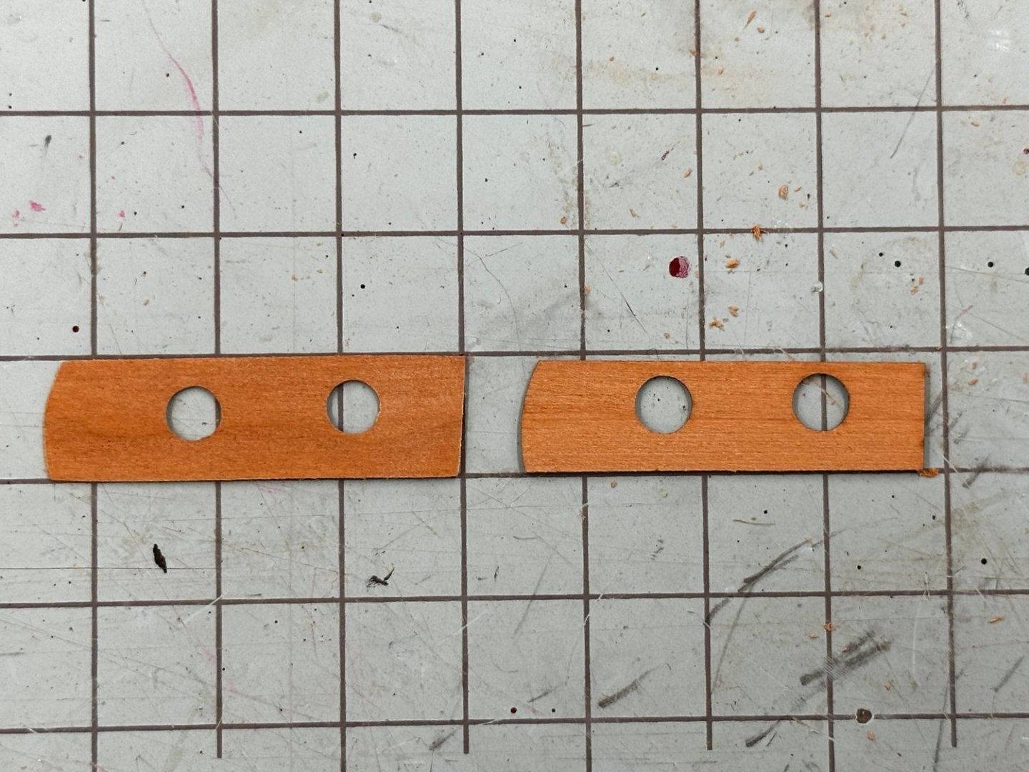
I managed to find/create a 1/32" thick sheet of cherry to manufacture some slightly larger pieces for the area between the cheeks. Here is my version and the kit version of the outermost piece. it is wider by just about the thickness of the horizontal lines on the the cutting mat. So here they are mounted on the starboard side. No WoP yet. And I did paint the underlying sheet black under the holes in case I get too lazy to actually drill the hawse holes. Since there are no anchors I wonder if drilling the holes is worth the "risk" of something "going wrong" - not that it every happens to ME! Now the real test - can I fit the upper cheek and not be too high on the stem. By the way in case it is not obvious by now I am not going to extend the black paint from the wales to the stem. Since I used the cherry stem I thought I might as well use the cherry cheeks etc. I will paint the area around the bowsprit hole black and continue the prototype paint scheme from there - at least that is my intention at this point.

- 389 replies
-
- 4
-
-
- winchelsea
- Syren Ship Model Company
- (and 1 more)
-
I have the starboard lower cheek in place. I thought I had it a little too high - at least the outboard side so that is why you see the missing paint above the cheek. As it turns out (doesn't it always) I now have the cheek a bit too low and maybe sloping up just a bit😝 According to the instructions (and my preliminary fitting of the upper cheek) the provided fillers should match up with the black strake. Clearly mine does not by about 1.5mm at the inboard end and about .5mm at the outboard end. Instructions allow as this is a distinct possibility and directs "creativity" to resolve. Hmmmm.

- 389 replies
-
- 6
-
-
- winchelsea
- Syren Ship Model Company
- (and 1 more)
-
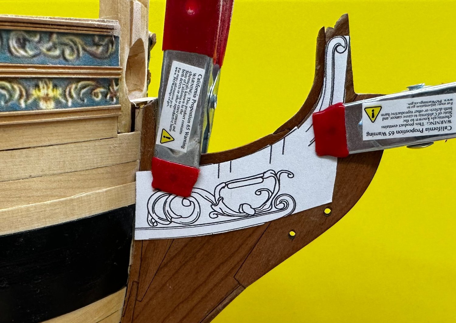
I decided to move on to the bow details while I let the port side gun port lids dry and "age" before going back to do them. The first thing that needs to be done is to separate the various pieces that form the upper and lower cheeks as there are slightly different in size. Getting them confused is much to be avoided. After assembling the hair brackets, and yes I broke both of the inner portions the uppers, one in two places; they did go together quite nicely. Once that was completed it was time for the cheeks. First I printed and cut out the starboard side template and lined it up as shown in the monograph. Then as a check I set the figurehead in place to see that it was going to fit with the upper hair bracket at his shoulder and the lower behind his feet. So far so good. Now to fit the lower cheek first per the instructions. To try and make the joint between the cheek and hair bracket as seamless as I am capable of accomplishing I clamped the lower hair bracket to the template. With this in place it is quickly obvious the the lower cheek is considerably longer than will be required. Which is a good thing as the thin piece on what will be the forward end is pretty fragile - I know I broke one off already. But no problem as there was still plenty to make a good mate with the hair bracket. I got the center portion fitted (per instructions) before considering the other two pieces - where by the way the forward end is even more fragile. Looks like a pretty close fit to me - there is WoP on the hair bracket but not yet on the cheek. Now to fitting the other two pieces of the lower cheek.

- 389 replies
-
- 3
-
-
- winchelsea
- Syren Ship Model Company
- (and 1 more)
-
I got the starboard side finished and as you see above am working the port side. For what it is worth here is the forward, starboard side gun port with the cover in place, as it will be in the end - no gun at the forward ports.
- 389 replies
-
- 4
-
-
- winchelsea
- Syren Ship Model Company
- (and 1 more)
-
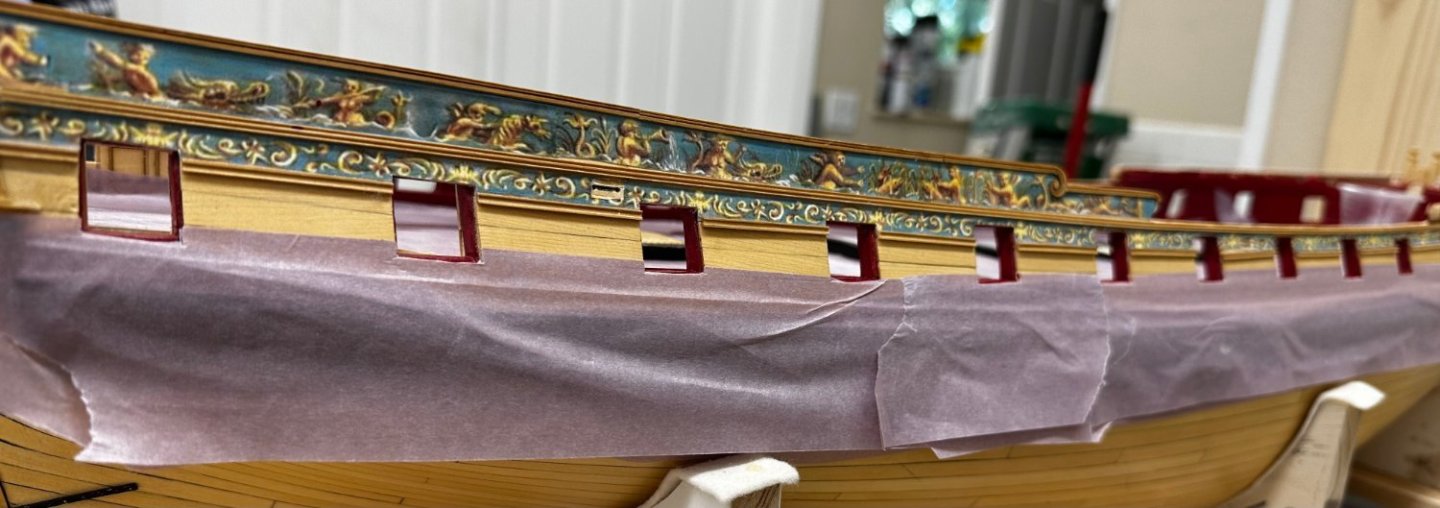
Here are the gun port covers for the aft port side. Clearly I could have done a better job picking the planks to match what is already there but... As can be seen I did not get the sides of the gun ports exactly straight. There are some "zig and zags" making the cover edges not exactly straight. I plan to try and true them up when the glue is dry without unduly affecting how they fit in the port. Since they will be open it is better (IMHO) to have the cover edges straight rather then they fit exactly since once the cannon are in place you can't close the cover to check the fit anyway.

- 389 replies
-
- 3
-
-
- winchelsea
- Syren Ship Model Company
- (and 1 more)
-
One note for those who may come after - I found it easier (compared to the method described in the monograph) to install the lid on the hull, locate and install the two "L" shaped hangers on the hull, then attach the hinges and glue the hinges to the lid with everything "together". I used some semi-large clamps to keep the hinge in contact with the lid while the glue (medium CA) dried. I put the two "L"s inboard of the gun port edges by 5mm on each side. This seemed to get the hinges where they are shown on the plans (more or less).
- 389 replies
-
- 3
-
-
- winchelsea
- Syren Ship Model Company
- (and 1 more)
-
Four of the five gun port "doors" (aka lids) installed on the starboard side. Two of the four will stay open without support. I will leave them closed for now so as not to attract stray clothing or appendages as work continues.
- 389 replies
-
- 4
-
-
- winchelsea
- Syren Ship Model Company
- (and 1 more)
-
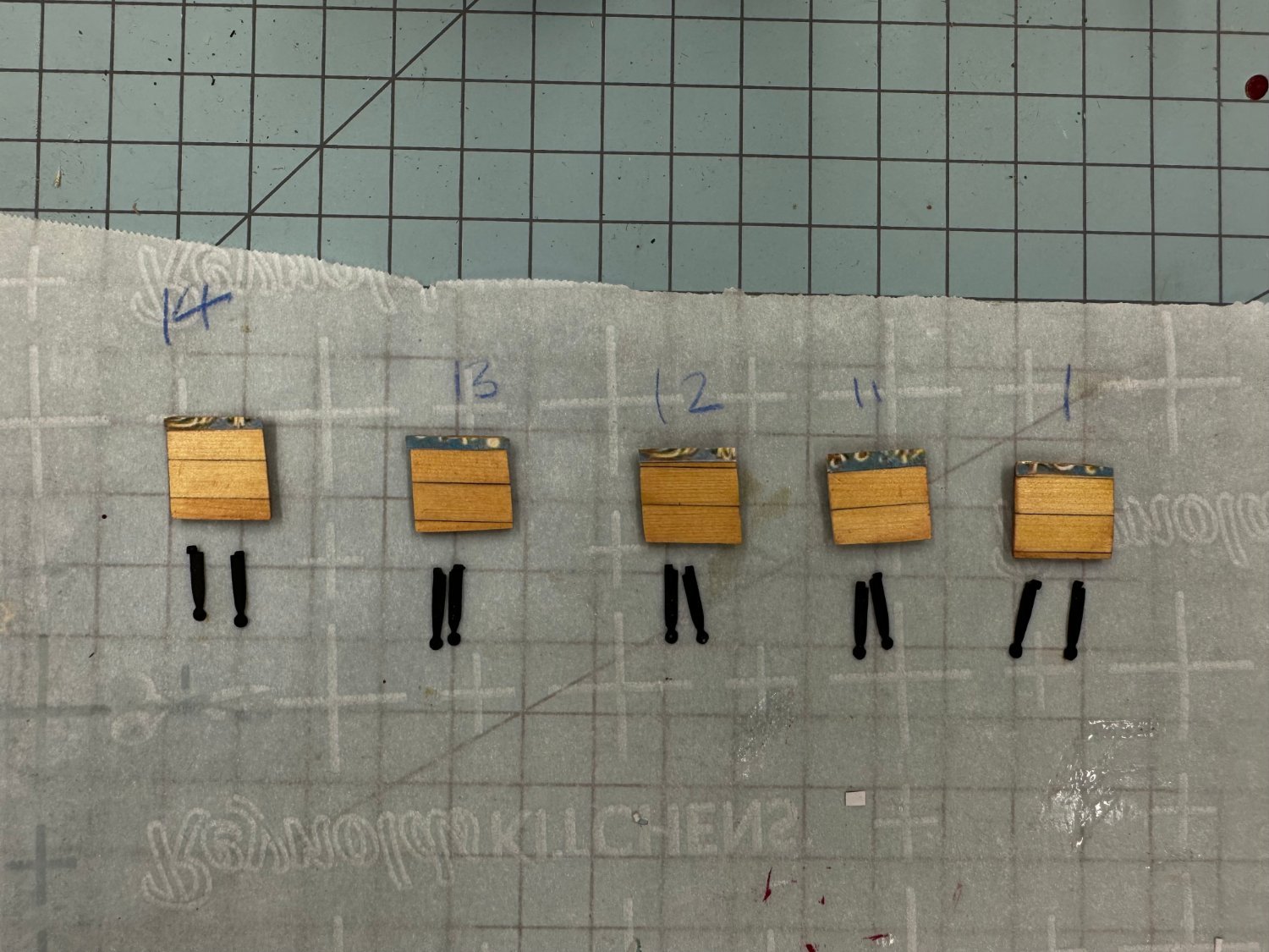
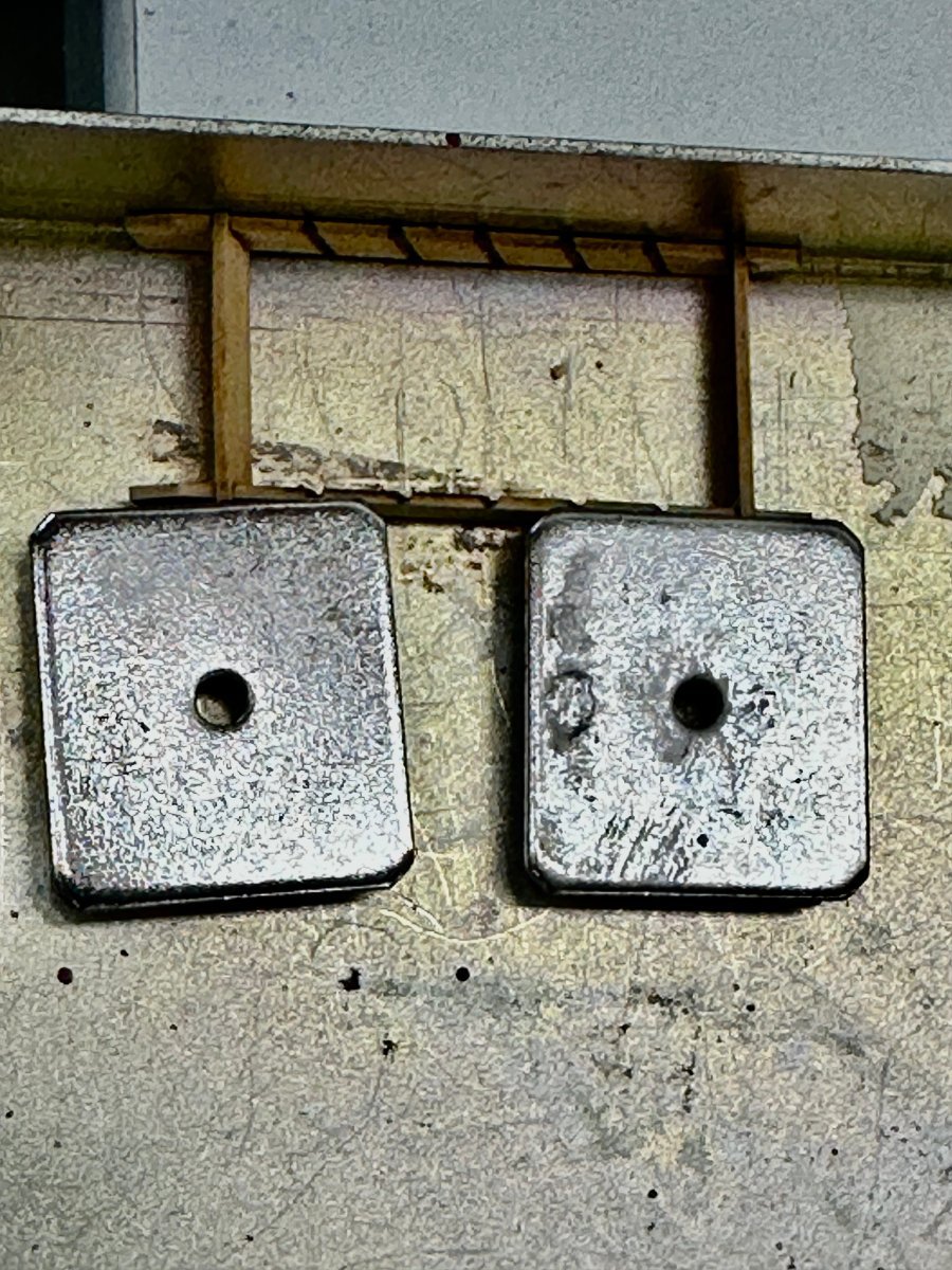
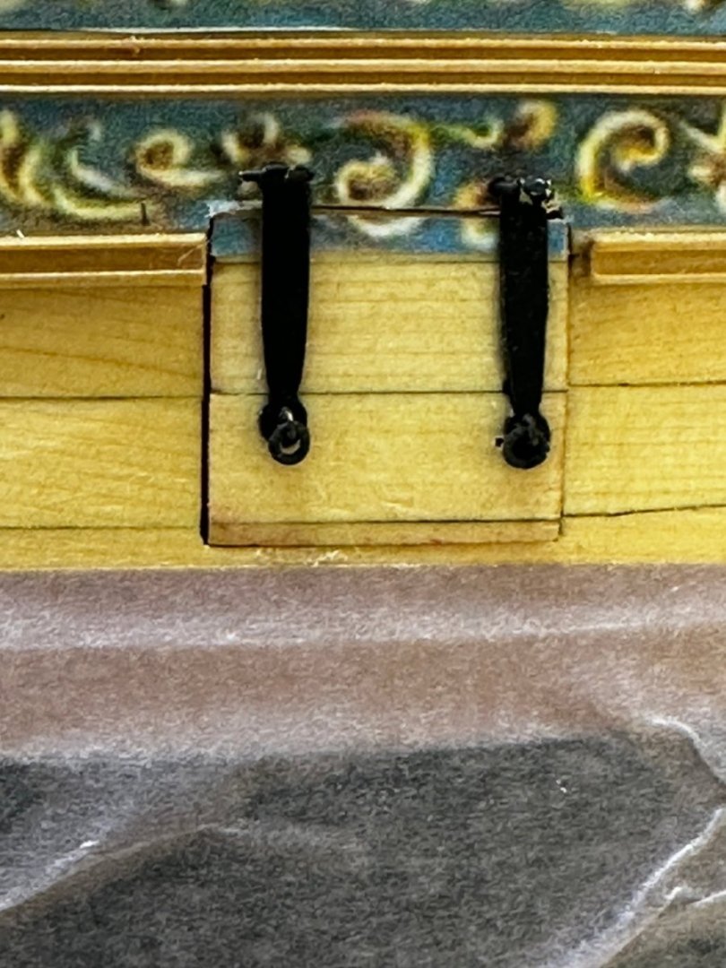
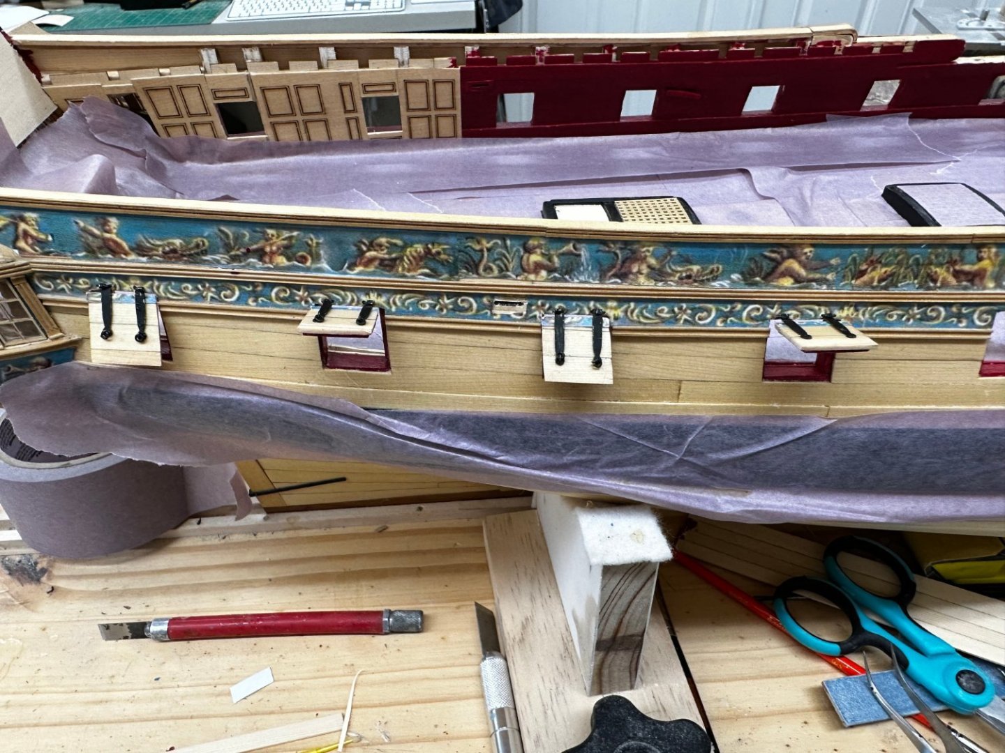
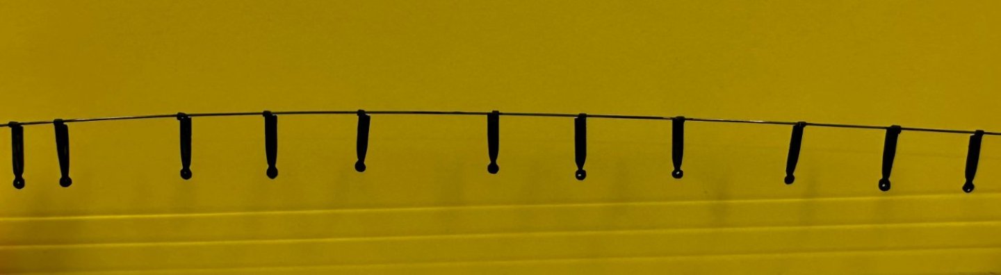
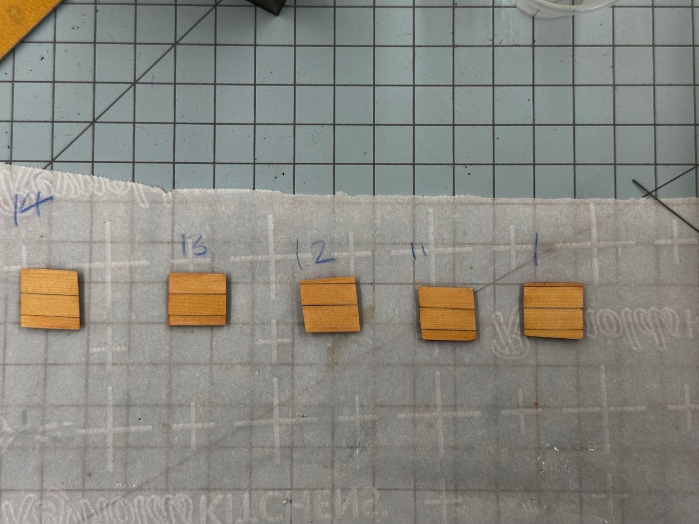
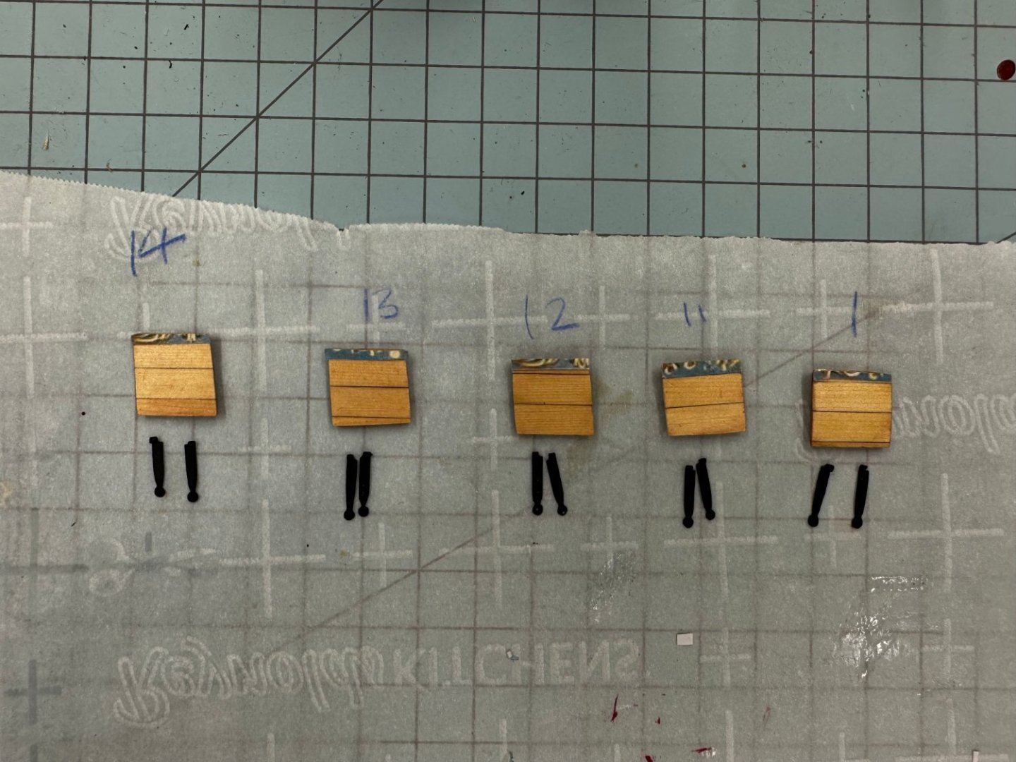
With the cleats and stagshead ready for installation I took a minute (or two) off from shaping the gun port hinges to get the port side "hardware" installed. As in Chuck's monograph it in not that easy to see them but they are there, trust me. I also took the opportunity to mask off the deck so I could touch up the paint on the hatches/coamings which got too close to the sandpaper while sanding the deck. And for good measure I masked off the outside of the hull around the gun ports to touch-up the red paint in the gun ports. I seem to have not done a very good job as almost every port had some "issue" with the red paint. So back to the gun port hinges. I decided to do one side of the port lids/hinges all the way through and then apply whatever lessons are learned to doing the other side. I decided to paint the hinges rather than blacken them. I have never had particularity good luck getting the various chemical blackening agents (and I have tried at least five) to stay on the brass and the hinges are going to be handled a good deal during installation (at least with me doing it). Besides that black gets on my hands and then "everywhere I don't want it". So here are the first five sets of hinges on a piece of .025" piano wire. The "left" ones are on the left. And here are the five hatches created as per the instructions, i.e. in place one plank at a time. Once the insides are on and painted it is more difficult to keep track of which one is which - hence the numbers on the parchment paper. Just as I was about to glue the hinges on the lids I remembered the frieze. Although it is sort of mentioned "after the fact" in the instructions I think getting the frieze on the lids before the hinges go on will avoid cutting really small pieces of frieze to go on either side and between the hinges. As I mentioned, since the ports are very likely going to be open the frieze on the lids does not have to exactly match what is on the hull but as it turned out that was not that hard to do (at least for me). So now it is time to glue the hinges on and get the lids mounted on the starboard side. Here are the lids and hinges "ready to go".

- 389 replies
-
- 4
-
-
- winchelsea
- Syren Ship Model Company
- (and 1 more)
-
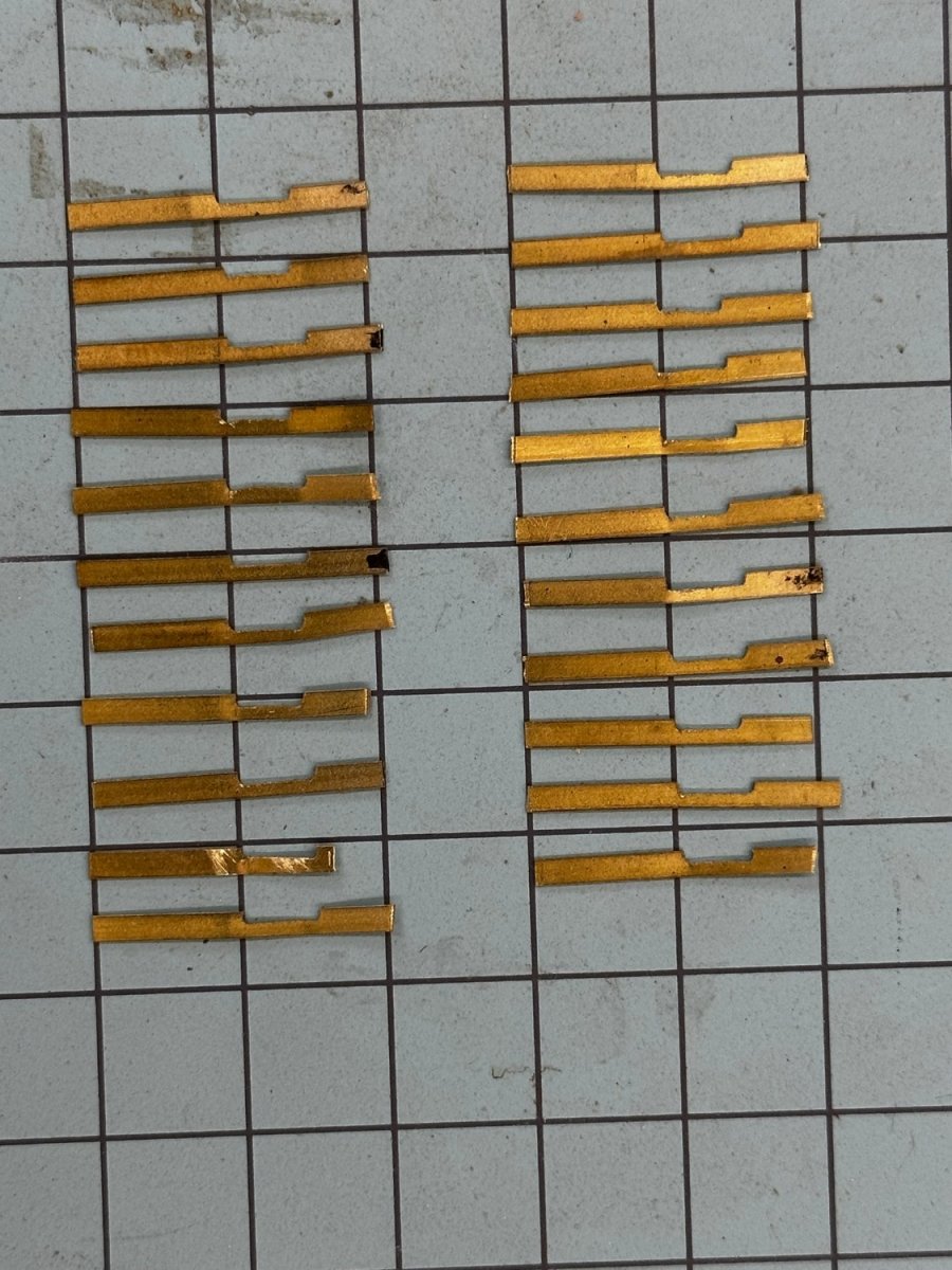
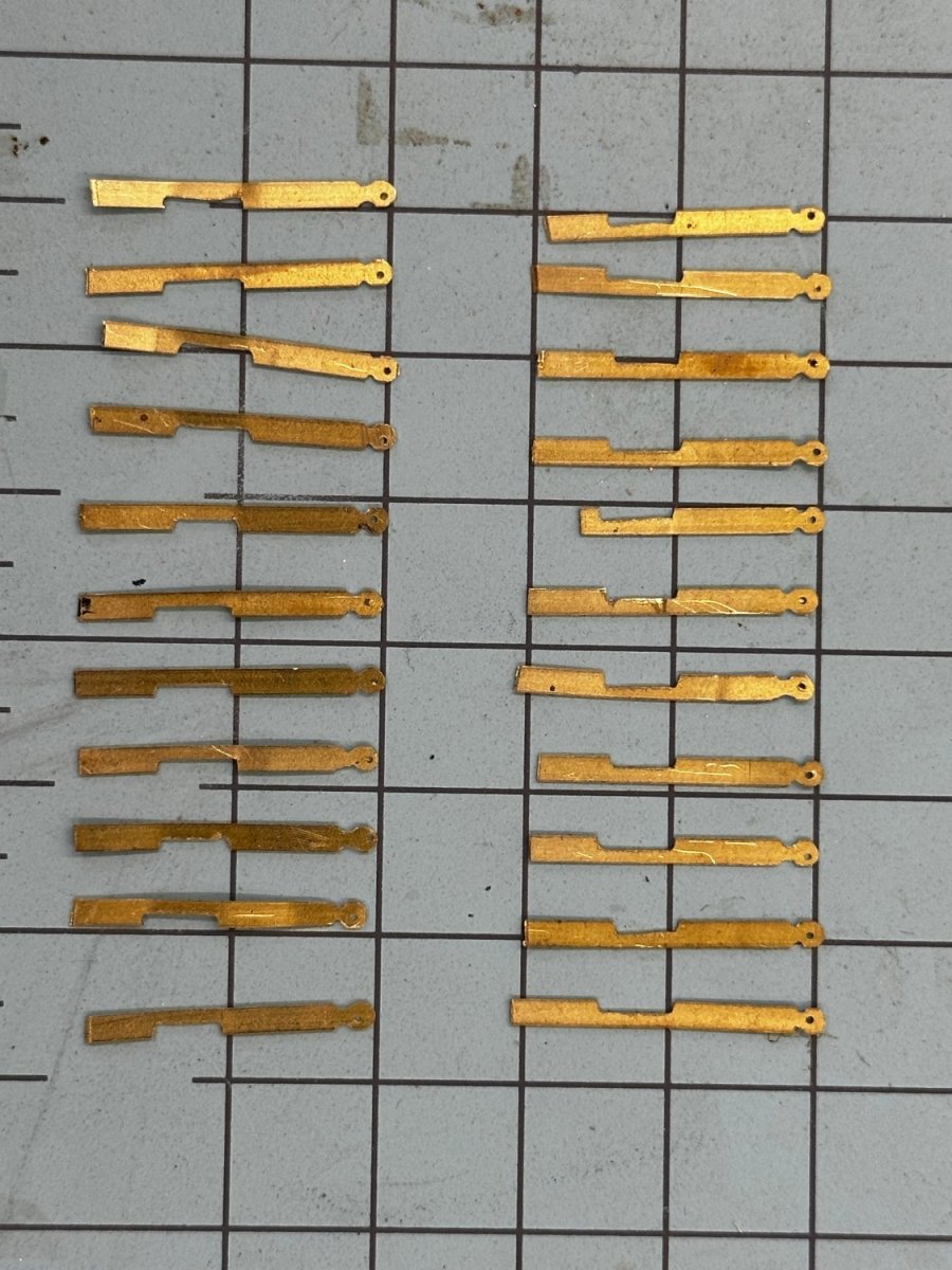
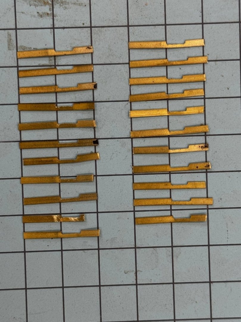
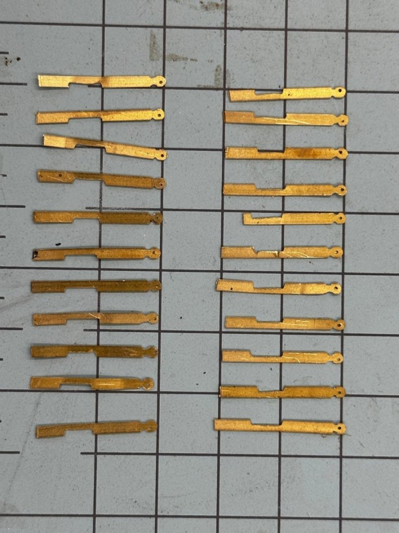
Progress on the gun port hinges is slow, very slow. I have 22 sets cut and the tail formed: Then I drilled the hole in what will be the bottom of the hinge - not exactly in the center although I am hoping this will n ot be too obvious with the eyebolt and split ring obscuring the "view" somewhat. Now comes the "fun" tapering the hinge and forming the tail.
- 389 replies
-
- 3
-
-
- winchelsea
- Syren Ship Model Company
- (and 1 more)
-
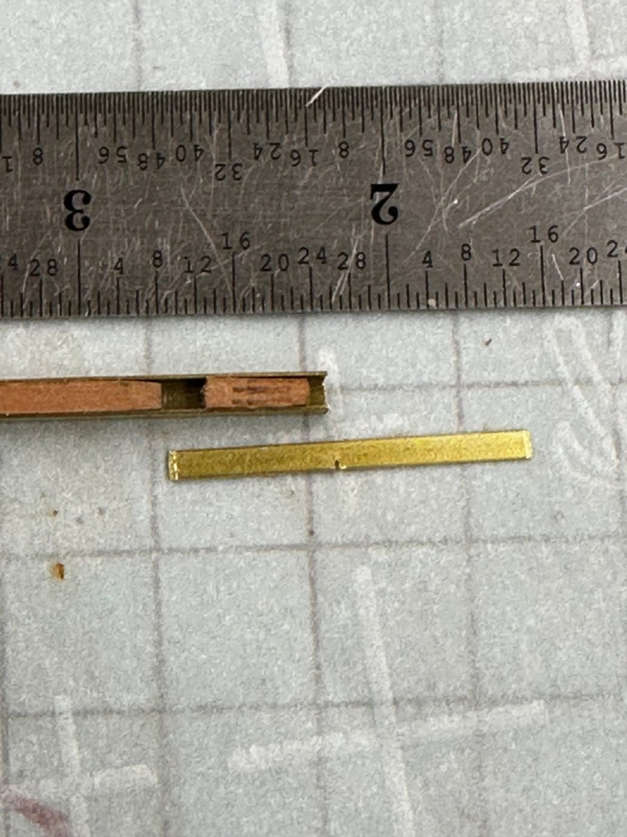
Thanks John - as it turns out I was mistakenly using 3/32" wide brass instead of 1/16". I measured on the drawing and it appears they are a bit wider than 1/16" so I will stick with 3/32" since I have enough stock to make several "mistakes" along the way.
- 389 replies
-
- 1
-
-
- winchelsea
- Syren Ship Model Company
- (and 1 more)
-
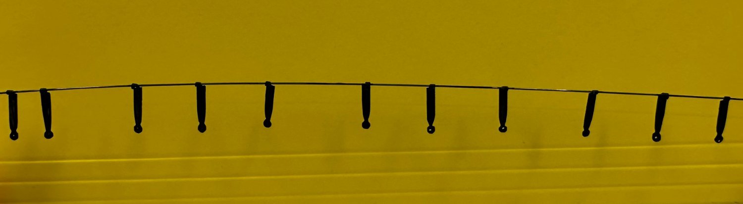
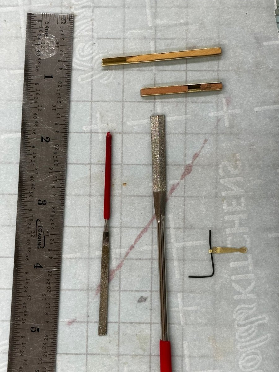
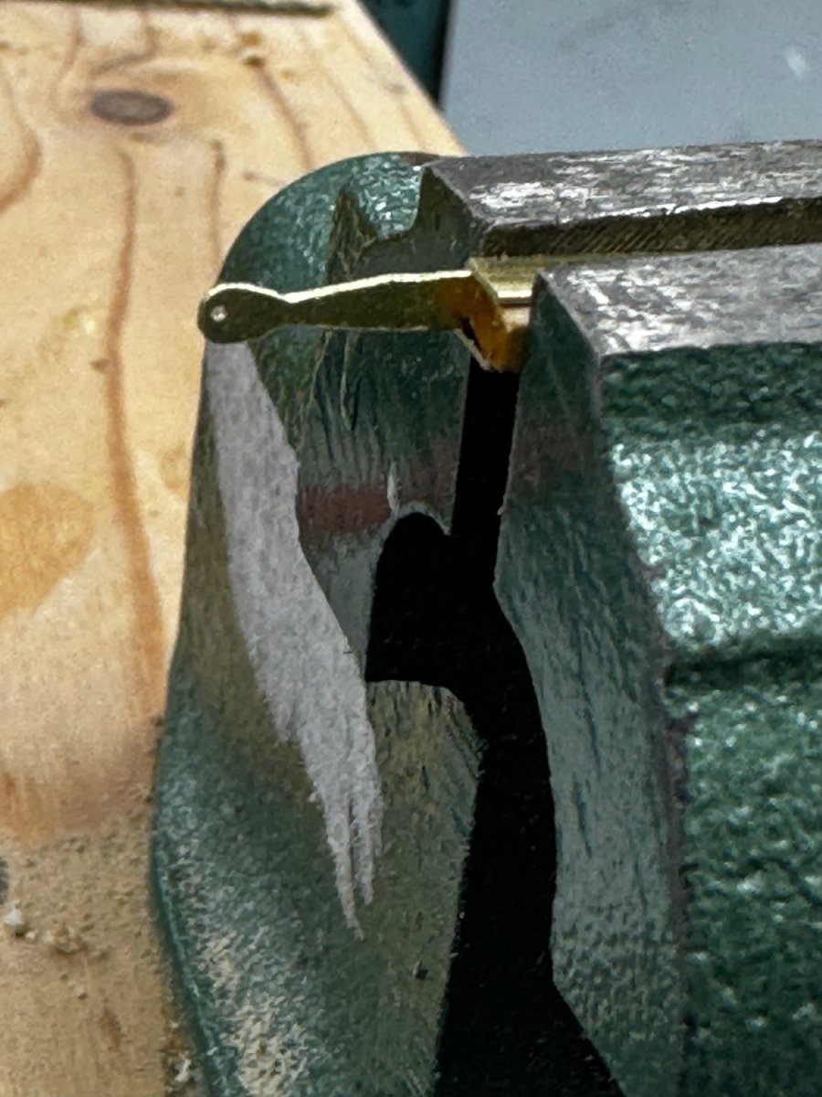
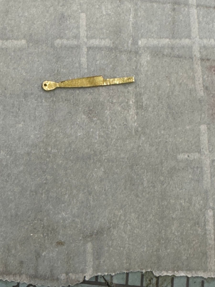
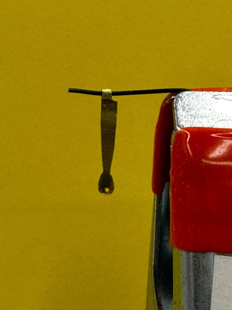
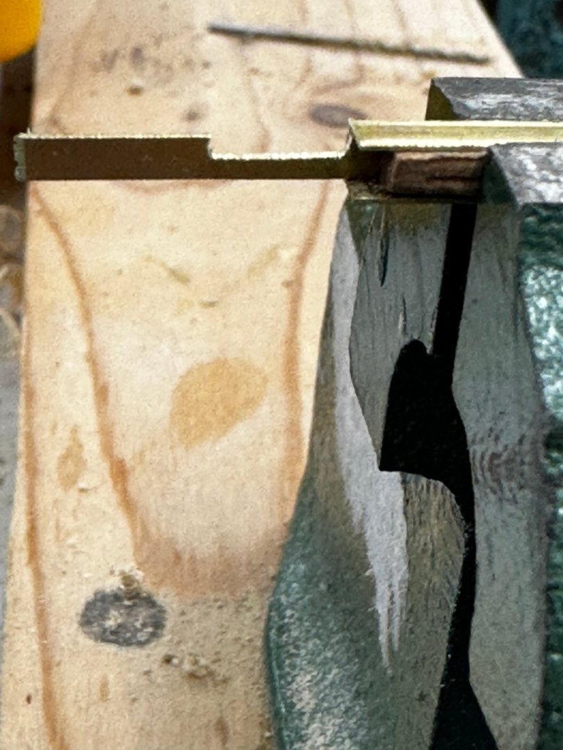
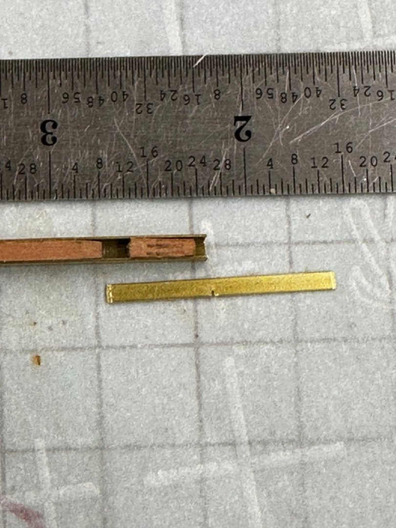
With the port lids in hand (or so I hope) I turned to the port hinges. I am most grateful that there are only ten ports with hinges, making 28 sets might be more challenge than I am ready to accept just now. Anyway, I perceive that the most important thing is to get all the hinges the same size. After looking through my pile of brass stock I luckily found several pieces of the required 1/64" X 1/16" brass still on the K&S cardboard sheet. I understand that K&S no longer sells these. I cut the first piece into 11 1" pieces - the piece is about 11.5" long. I also found some 1/8" brass channel which holds the 1/16" between the side walls almost like it was meant to. So I cut off two pieces, and found some scrap wood to use as "filler/stoppers" inside the channel. By my measurement each hinge is 17/32" long below the hinge. So I put one of the stoppers into the channel with 17/32" of the brass exposed. and used my 90 tpi Exacto saw to cut a slot half way through the piece. I then used a flat file to remove the material outside the cut. I used the other piece of channel to make a holder that exposed the "business end" of the hinge so it could be shaped per the instructions. I made the mistake of drilling the hole in the end of the piece before I shaped the end. Although contrary to the instructions I think it best to wait until the lower end of the hinge is shaped before drilling. I think it easier to adjust where the hole goes depending of how the end is eventually formed. Now I cut off the excess brass and filed the "tail" down to about .008" thick trying to make sure it got that thin on the entire length as the tendency is to end up with a taper with the thickest part at the inboard end - where the most bending is going to take place. Here is what it looks like now. Again the hole should be higher up. Now all that is left is to form the eye. I used a special pair of "bending" pliers that has a tapered circular section shape on one jaw and a curved jaw to fit the circular section on the other side. I had to stay way down on the narrowest part of the circular jaw and cut off the end of the "tail" incrementally as it became clearer how much was going to be needed. Here is the "final product" hanging from apiece of 24 gauge wire. It is not an "interference fit" by any means (a 22 gauge wire would fit as well). Here are the tools I used but I am still trying to find a better way to make the eye that get closer to the 24 gauge size - which is .023" as best I can tell.


- 389 replies
-
- 7
-
-
- winchelsea
- Syren Ship Model Company
- (and 1 more)
-
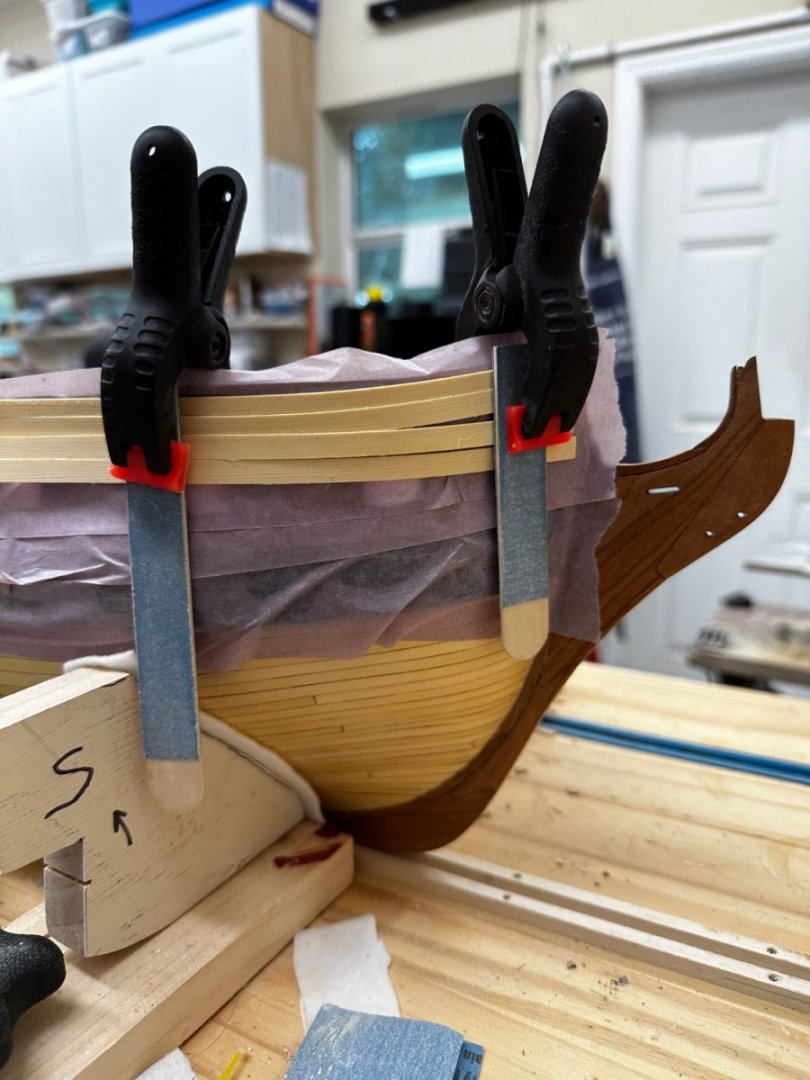
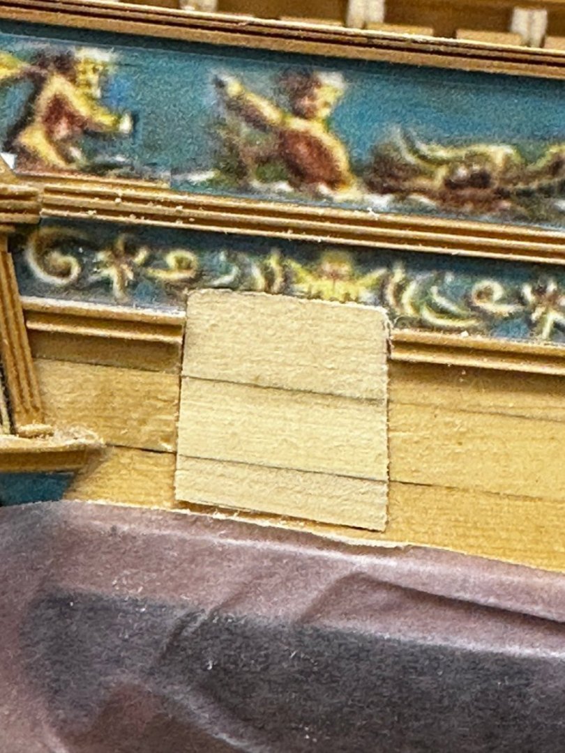
Building the port lids is not terribly hard, just tedious; rough shape, measure, sand a little, measure, sand a little more, measure, sand yet a bit more.... At least for the aft port lids this seemed to work out per the instructions. Here is the starboard port 14 port lid as glued up and in place. Getting frieze to match exactly looks to be a challenge but it would be hard for anyone to tell on the open ports how well they match without a good deal of effort. I will give it the "old college try" but am not going to "break my sword" on it. At the bow I wet some planking material and clamped it to the bow and let it dry overnight. I am leaving port one for last on each side. Or did the Royal Navy number the ports with the even to port and the odd to starboard as would have been done in the USN of 30 years ago (I can't comment on the USN of today).
- 389 replies
-
- 1
-
-
- winchelsea
- Syren Ship Model Company
- (and 1 more)
-
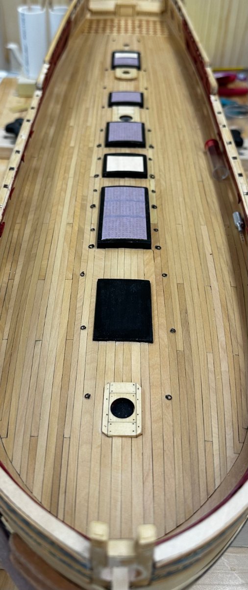
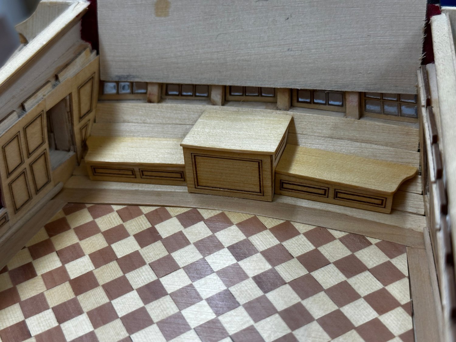
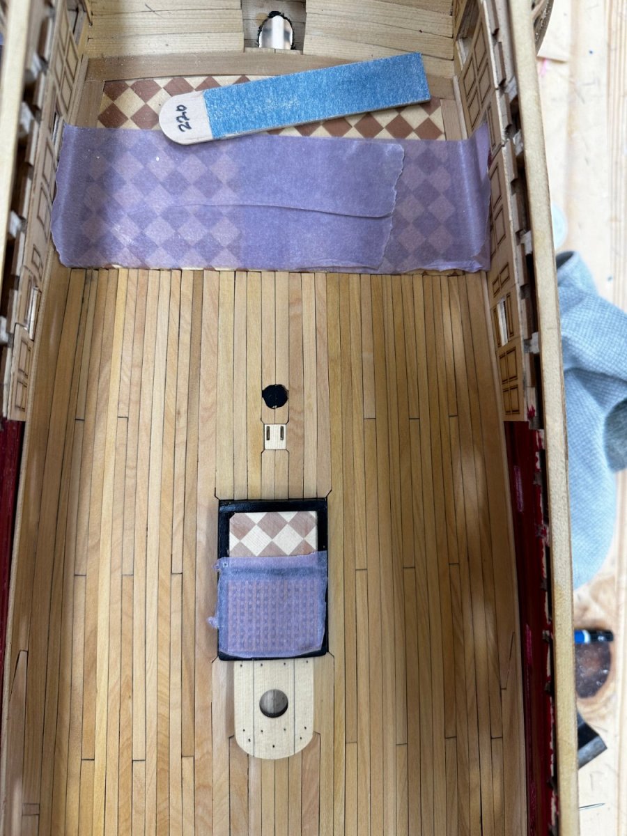
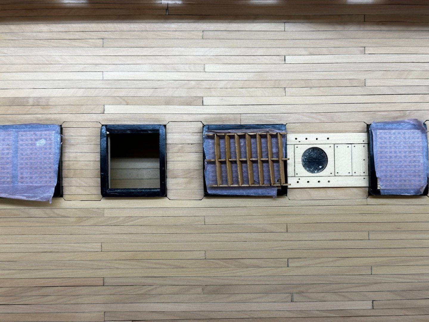
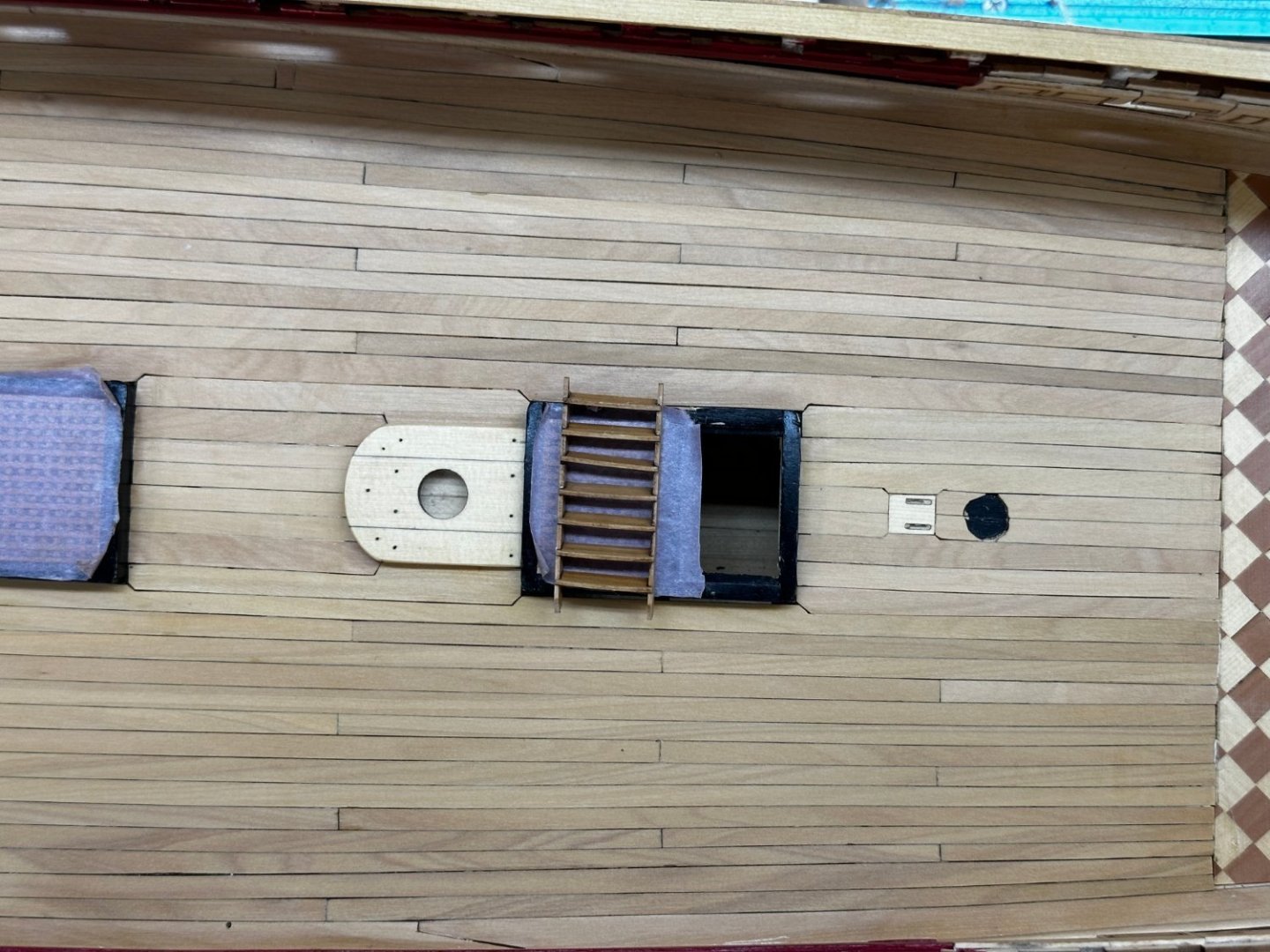
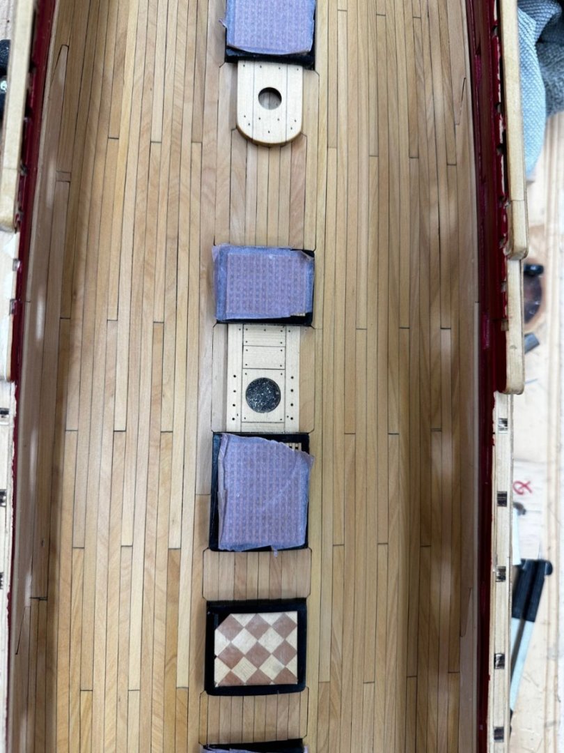
Got three parts of Chapter 5 completed. The cabinets in the Great Cabin - need another coat or two of WoP but there they are. The decking got it fourth and final coat of WoP and the two ladders have been assembled, WoPed but not yet actually installed. Will get to that when the decking is dry. Now on to the "real" fun - gun port lids and hinges not to mention touching up the hatches and such that got too close to the sandpaper while finishing the decking. Now on to the "real" fun - gun port lids and hinges not to mention touching up the hatches and such that got too close to the sandpaper while finishing the decking.


- 389 replies
-
- 5
-
-
- winchelsea
- Syren Ship Model Company
- (and 1 more)
-
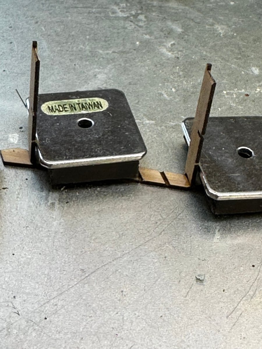
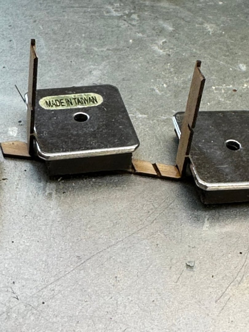
Between coats of WoP fore the decking I am proceeding with building the ladders and making the cleats and other hardware that goes on the inner bulwarks. Here are the beginnings of the two sets of ladders. The single set has the upper and lower treads glued into the frame and drying in the metal "box" with the magnets to hold it in place. For the double ladder I have the upper/lower treads glued to one side waiting for them to dry before adding the other frame member. Finally I sanded the laser char off the cleats, added a .020" phosphor-bronze wire for mounting (way too long now but it makes for a convenient "handle" while painting) and painted them red. Likewise with the staghorns.


- 389 replies
-
- 6
-
-
- winchelsea
- Syren Ship Model Company
- (and 1 more)
-
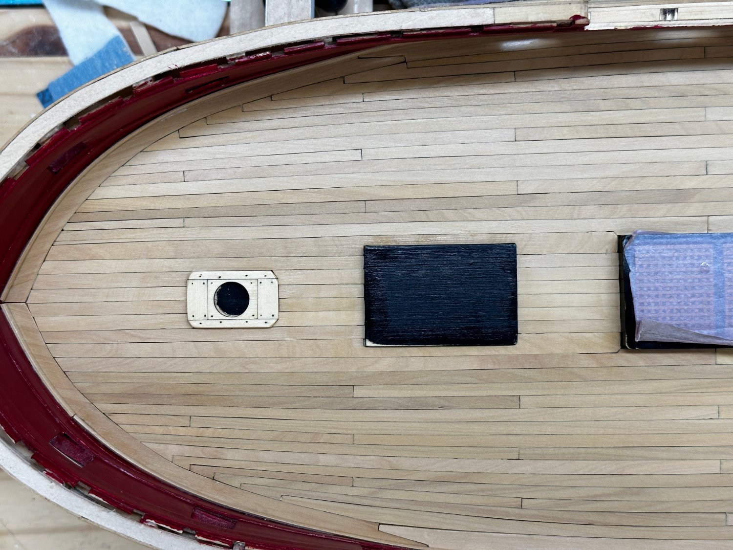
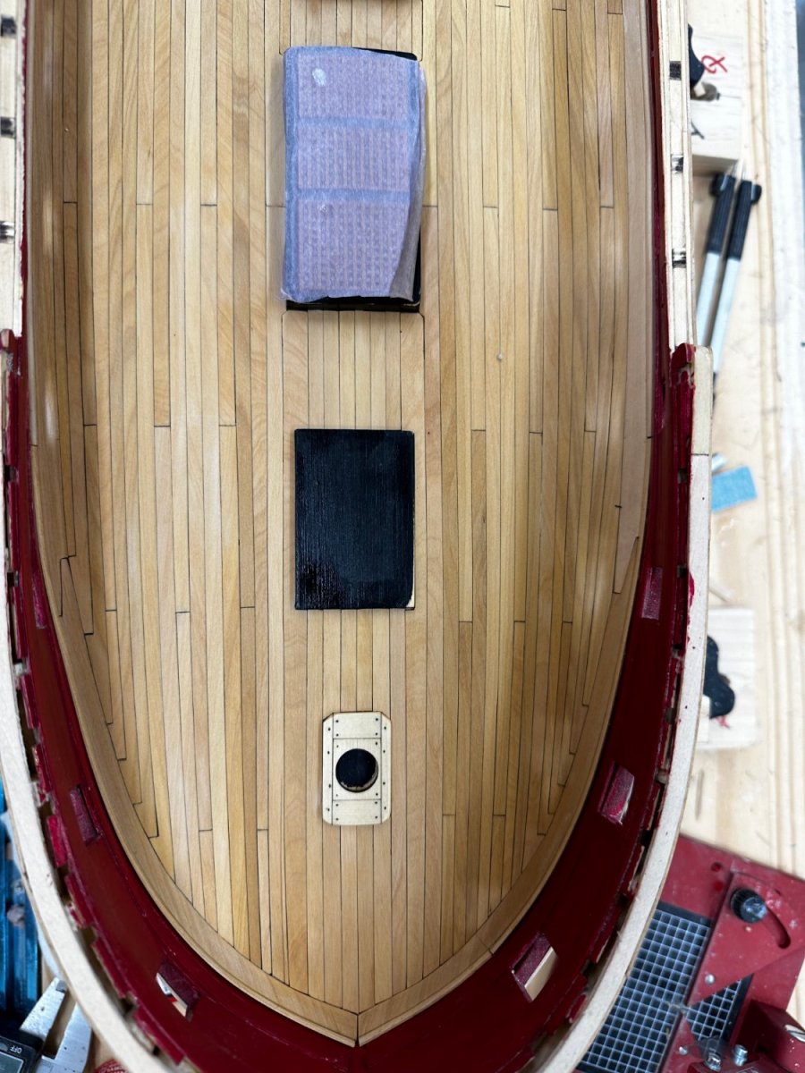
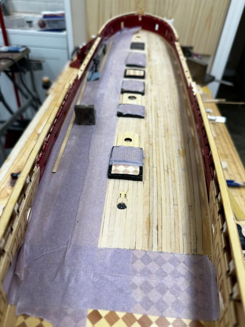
Deck planking completed, sanded with 150 then 220 grit and wiped down with paint thinner. When the thinner dries I will hit with 320 grit, then more thinner and WoP when the deck is dry from the thinner. Need to clean up the shop before tackling Chapter 5. Lots of small pieces of planking and "tools of the trade" for deck planking that can be put/thrown away until it is time to work the quarter and fo'c'sle decks (What there is of them).


- 389 replies
-
- 4
-
-
- winchelsea
- Syren Ship Model Company
- (and 1 more)
-
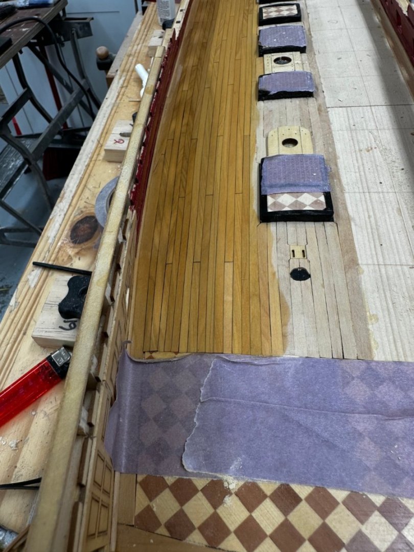
Thanks Rusty. Starboard side planking completed. Now to get both sides sanded down and WoP applied.
- 389 replies
-
- 3
-
-
- winchelsea
- Syren Ship Model Company
- (and 1 more)
-
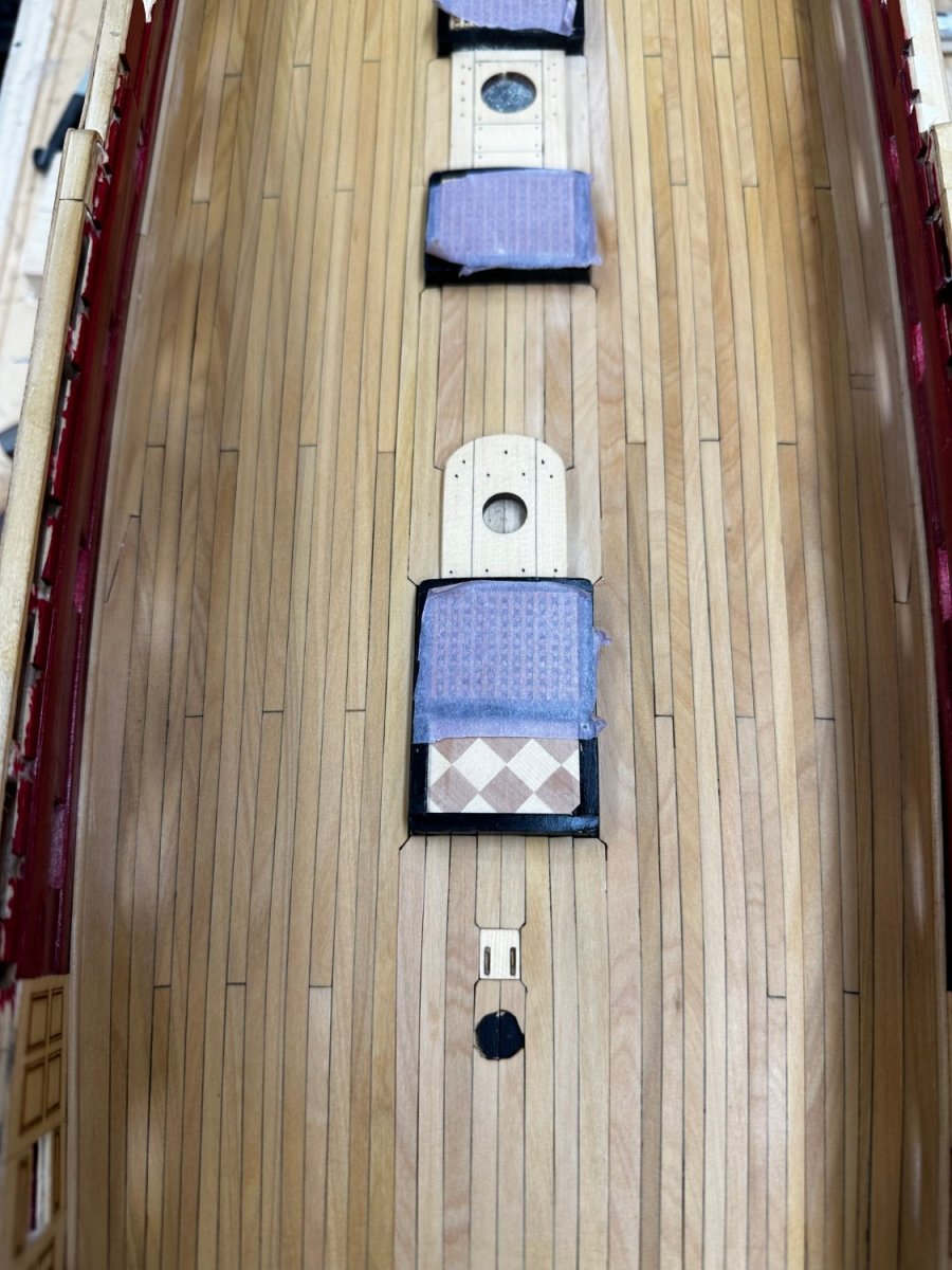
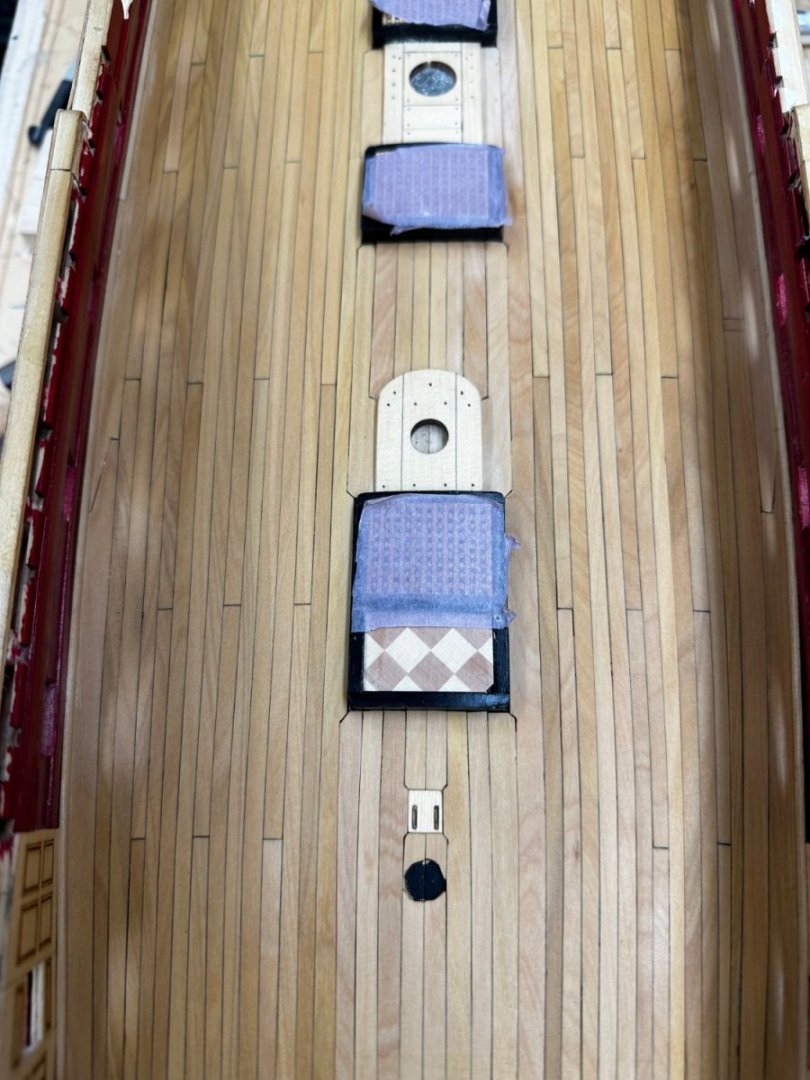
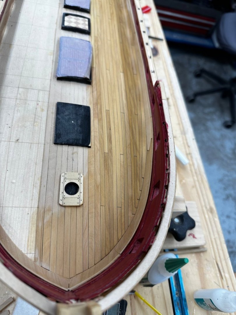
Port side deck planking completed. Here it is after a 150 grit sanding and tack cloth. 220 and 320 grit sanding will wait until both sides are done. In the mean time I plan on covering this side with masking tape to avoid any "spill-over" from the ongoing work. For whatever reason it took me one more scarf than the plans show. The boxwood I have seems to have more than it share of streaks and color differences but it is what I have so... Is every seam as tight as I might have liked - no, but a least a few of them will be under cannon so will not be easily noticed. Now for the starboard side.
- 389 replies
-
- 10
-
-
- winchelsea
- Syren Ship Model Company
- (and 1 more)