cdrusn89
-
Posts
1,918 -
Joined
-
Last visited
Content Type
Profiles
Forums
Gallery
Events
Everything posted by cdrusn89
-
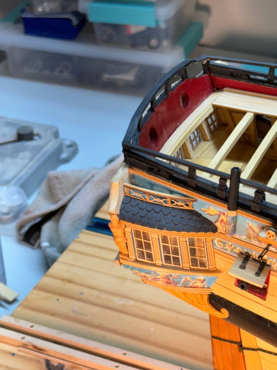
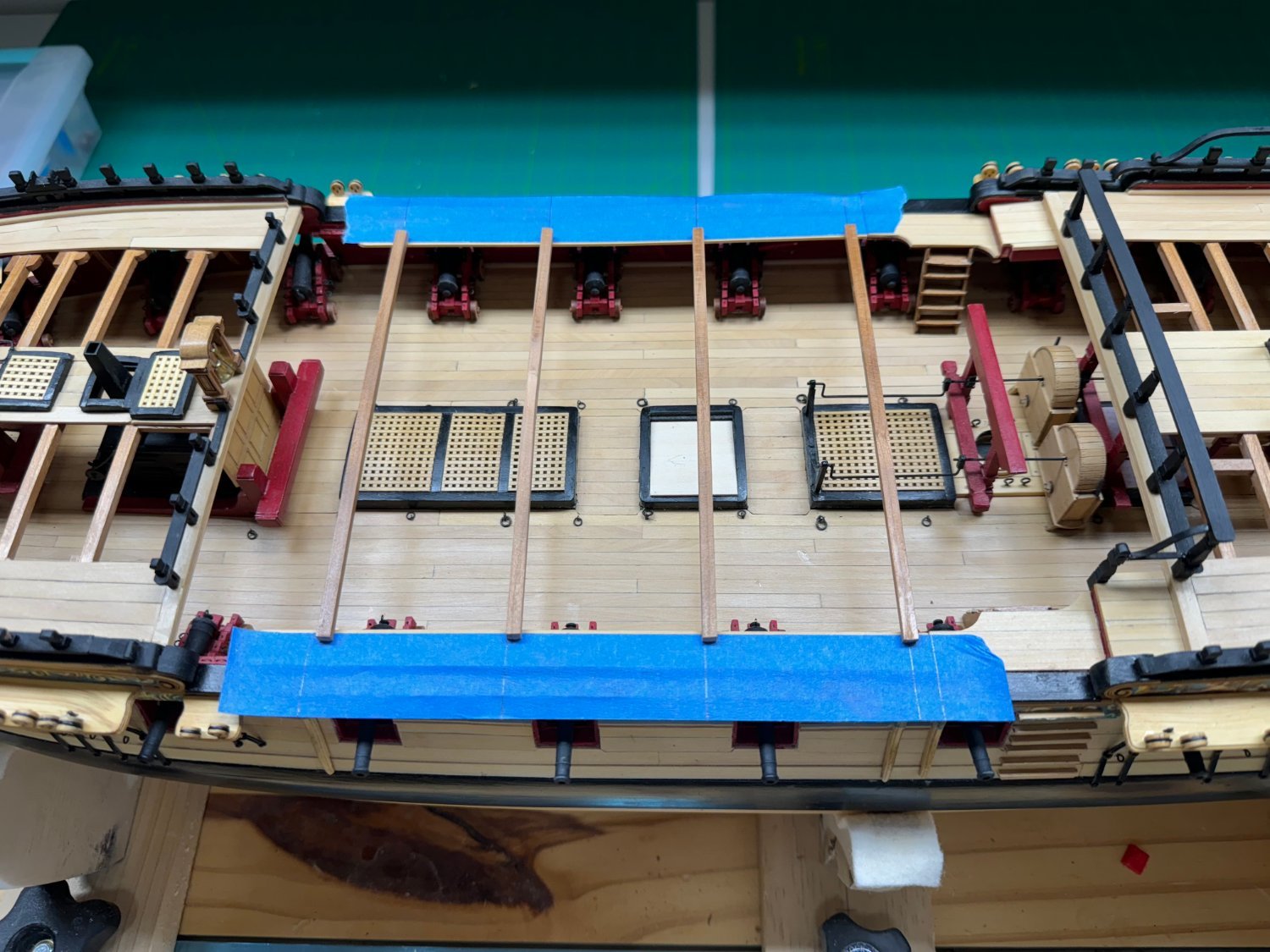
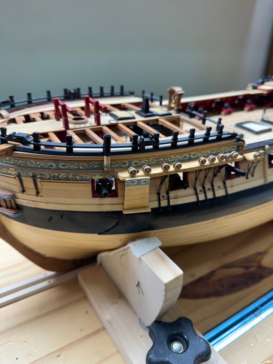
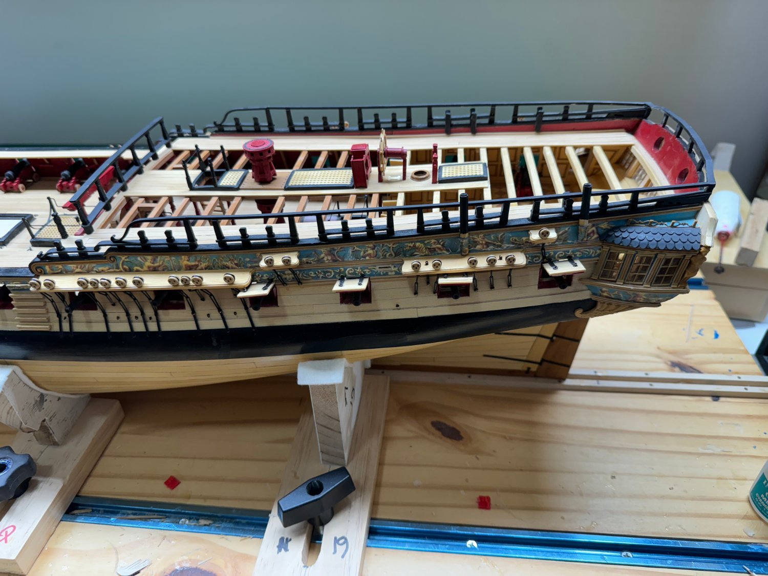
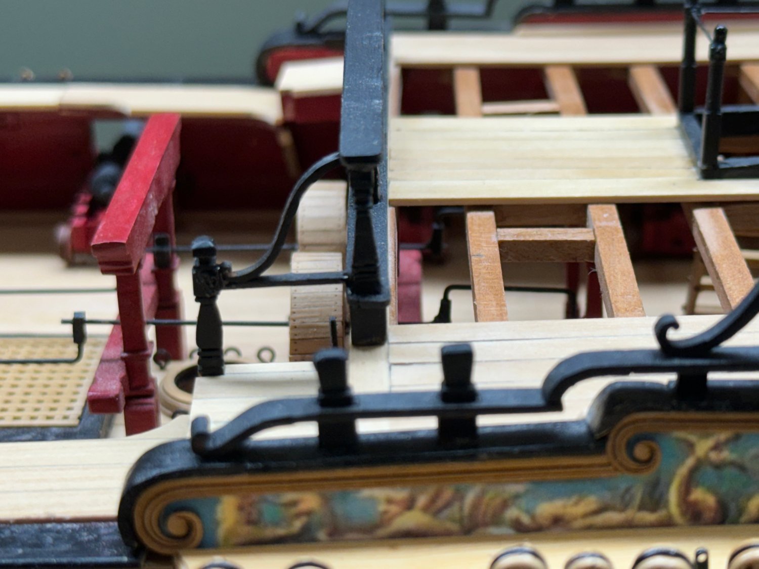
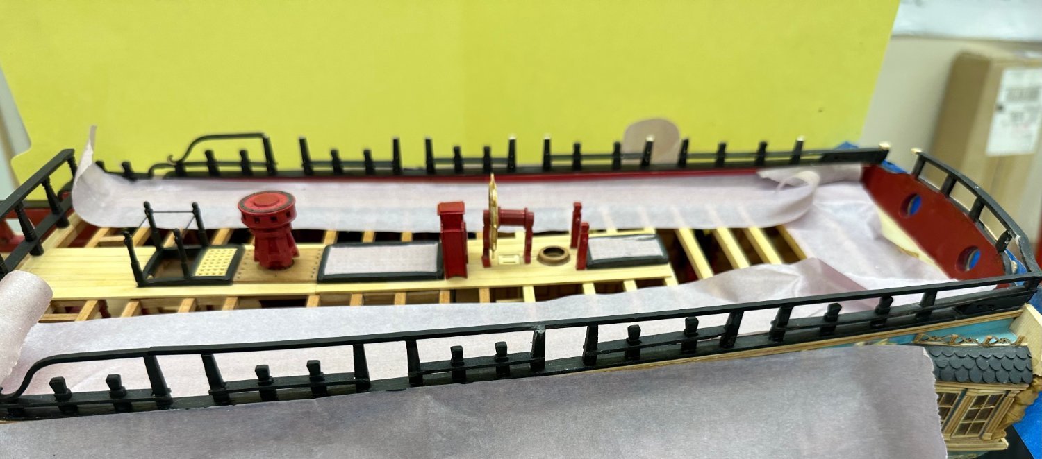
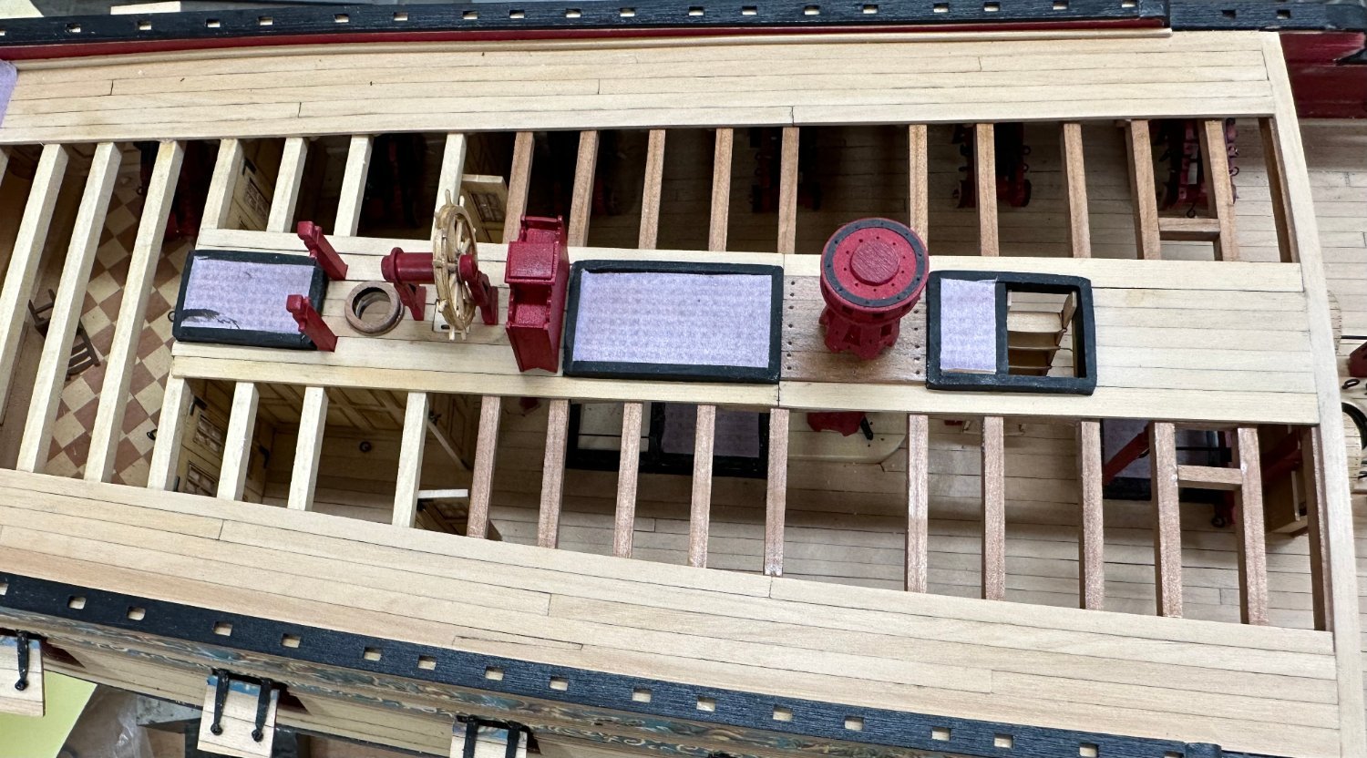
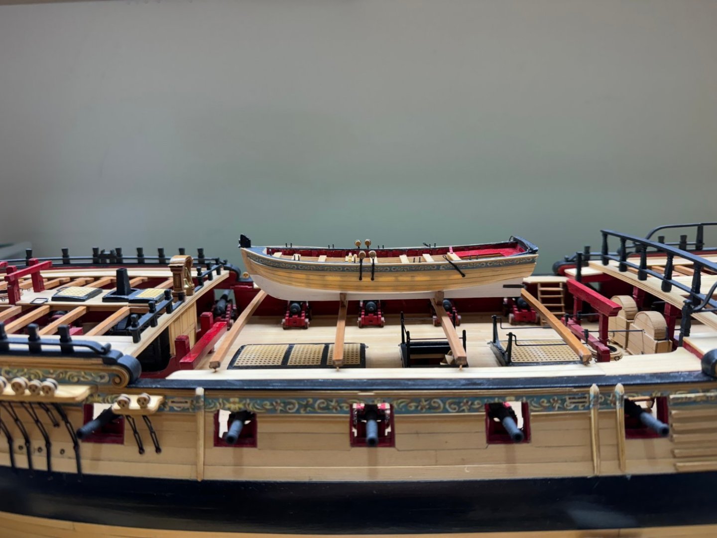
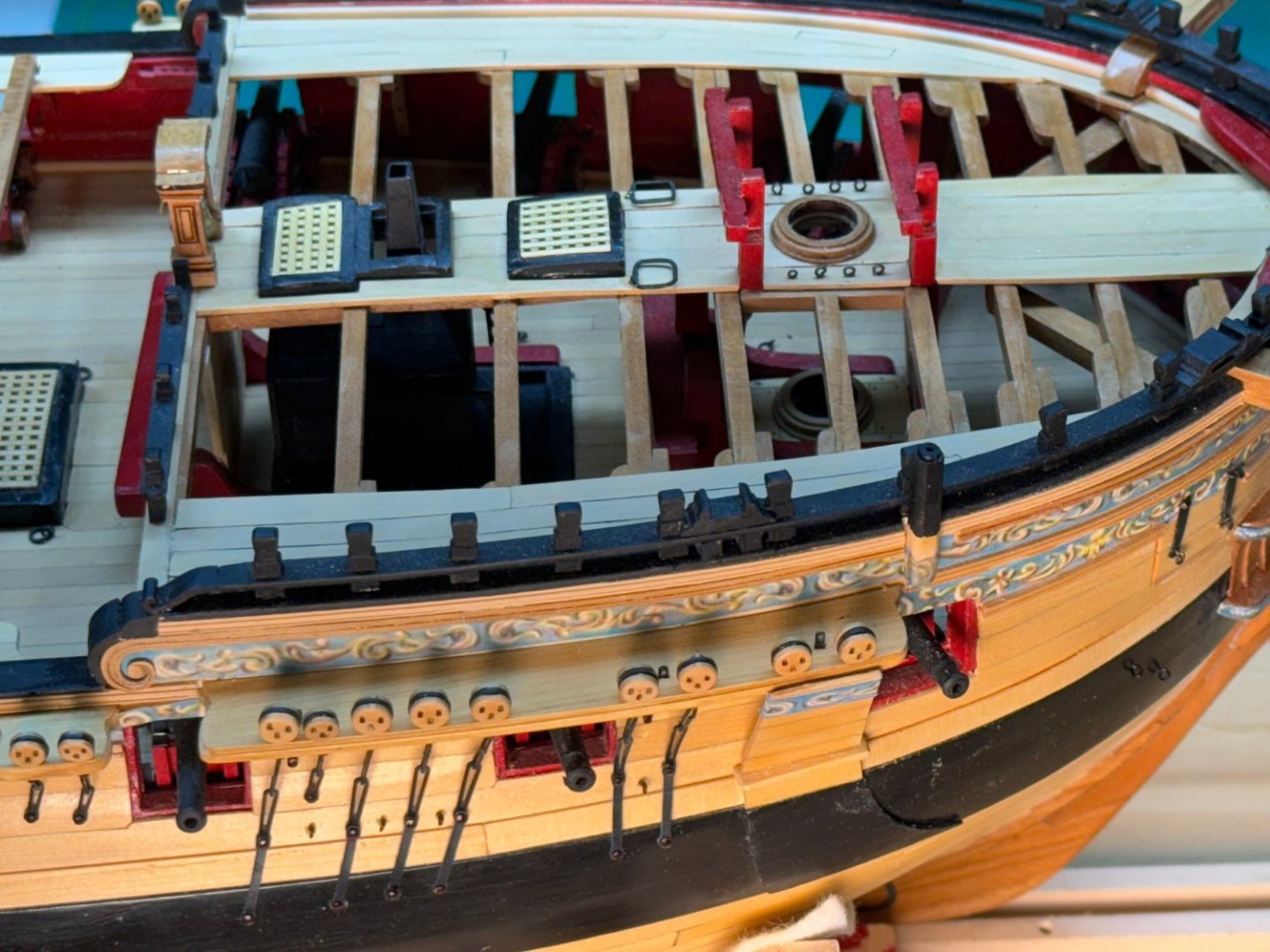
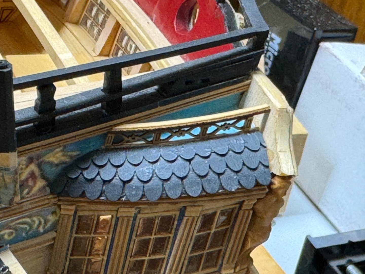
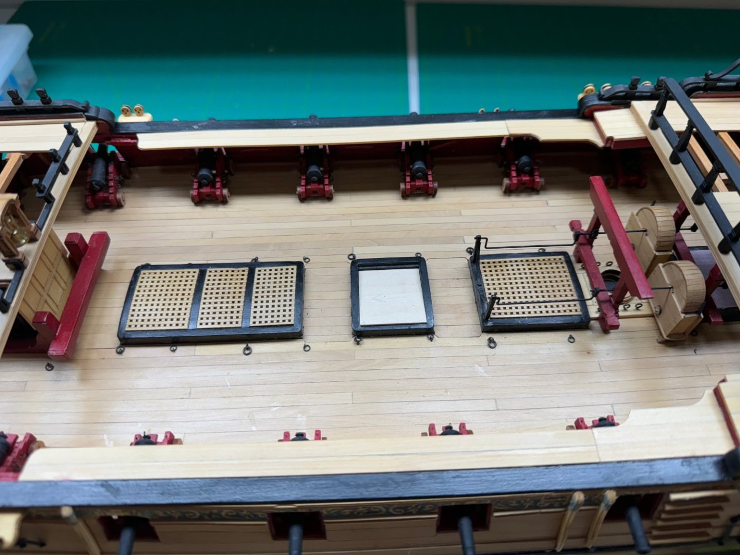
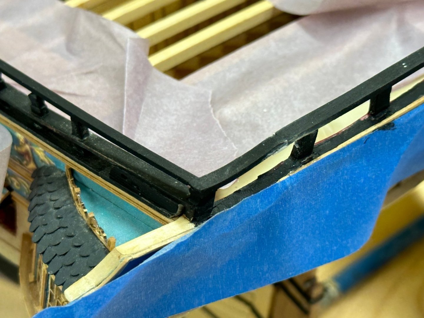
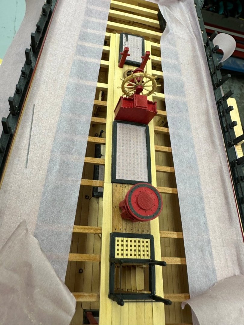
 Deck beams completed and long boat in place (just sitting there at the moment). May need to adjust the long boat position aft some and add a support on the after most deck beam. But that is for "later". Now I fixed the railing on top of the starboard q-gallery, added the swivel cannon supports on the starboard side and the newel post and railing. That about wraps up Chapter 11. On to Chapter 12 after Christmas.
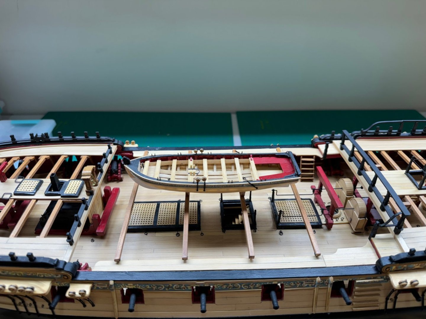

- 389 replies
-
- 11
-

-

-
- winchelsea
- Syren Ship Model Company
- (and 1 more)
-
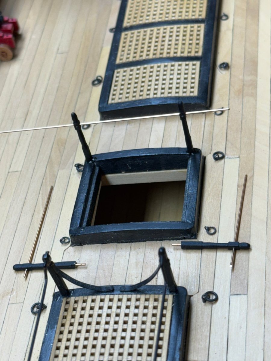
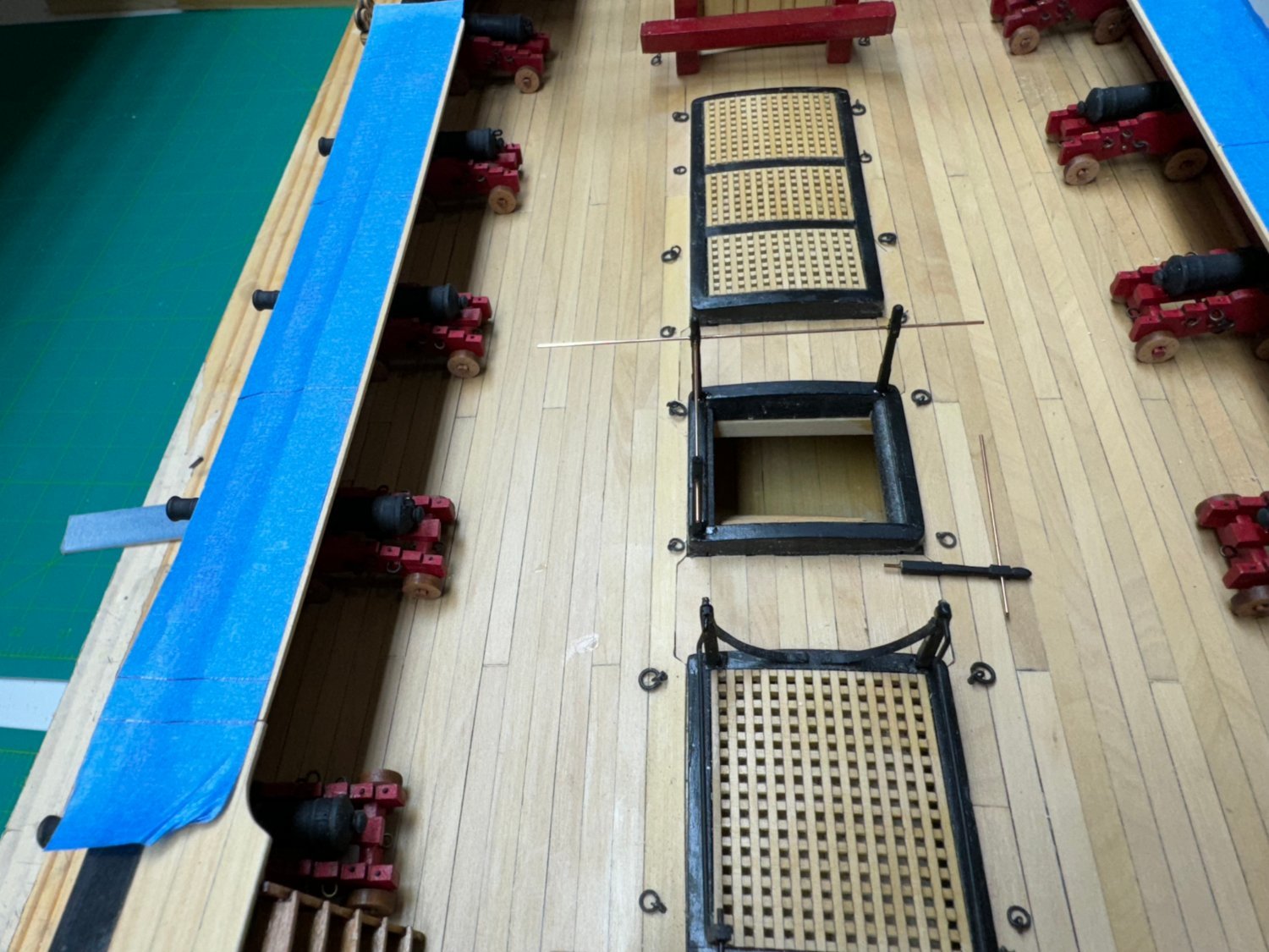
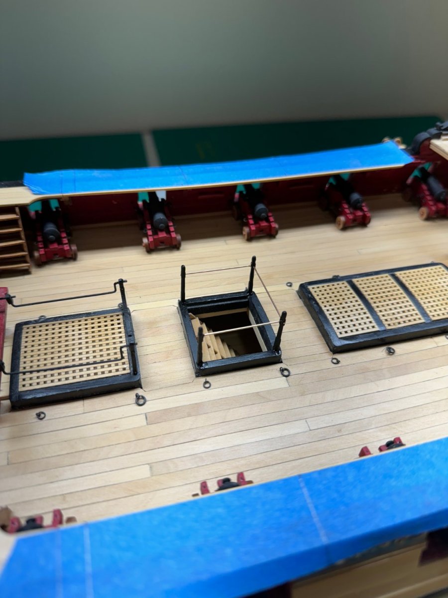
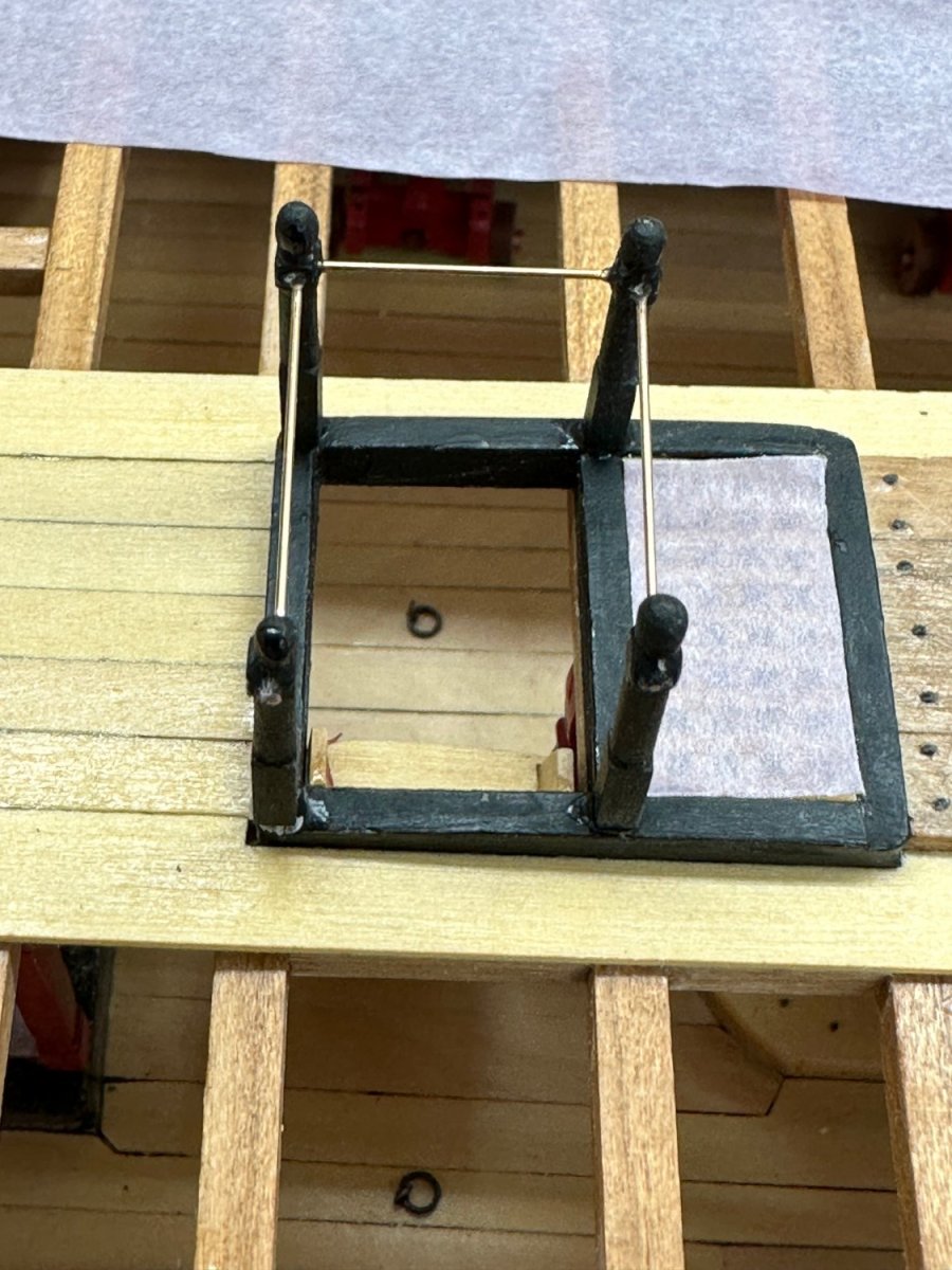
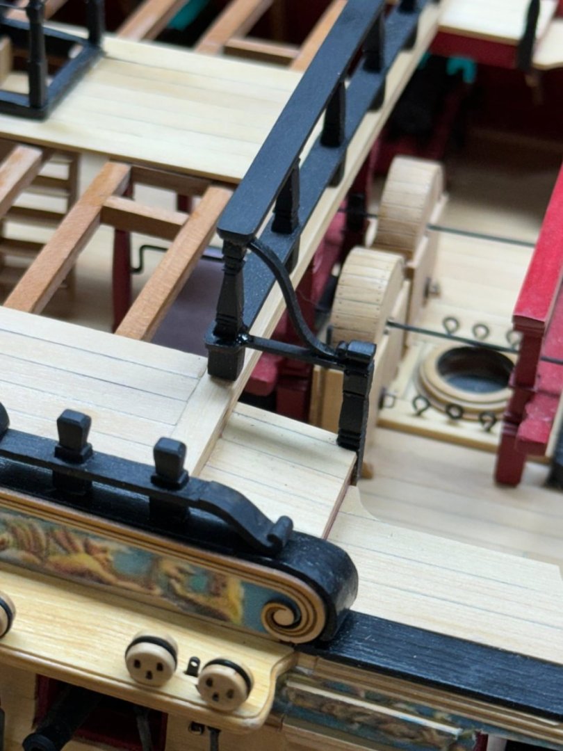
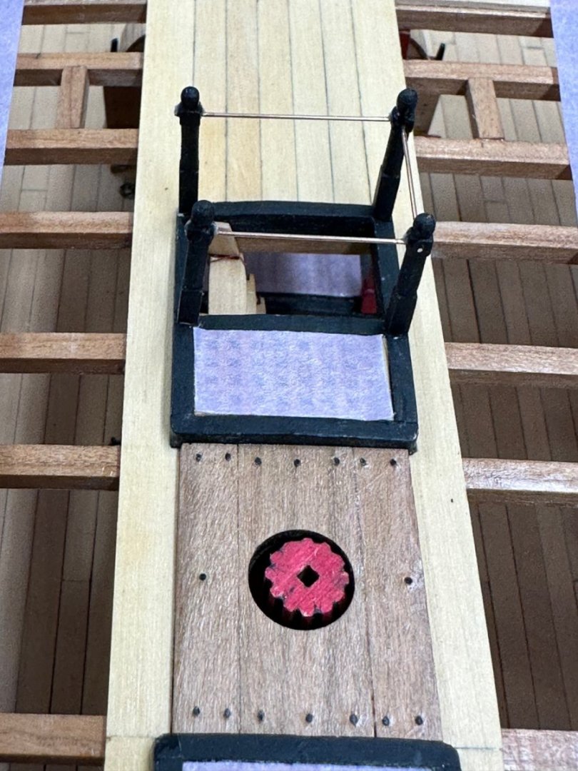
I must have missed the section where the railing around the main passageway was installed. Unlike the two previous railings I used 1/16X1/16 boxwood for these rather than the 3/32X3/32. It is hard (for me) to tell the difference but the small ones are probably more in scale. I used the Dremel to fashion the stanchions as before but bearing in mind the smaller cross section I was conscious not to use too much pressure and let the file do the cutting. Getting four that were nearly identical was no easier - I think I made 10 before I had four that were close to identical. I drilled #72 (.025") holes in the center of the bottom and all the way through the upper square cross-section on all four and then a hole perpendicular to the first one but not all the way through on two stanchions. I threaded a piece of .025" phosphor-bronze wire into the center hole in the bottom of all four stanchions and the through holes on the pair with two sets of holes - these will be the stanchions parallel to the opening. I drilled a #72 hole in the hatch coaming on the forward side of the hatch and set the two forward stanchions in place. I adjusted the location of the stanchions to get them vertical and then used a drop of thin CA to hold them in place. In the photo above you can see the installed set and the two that will form the sides of the railing I used a similar procedure to mount the other two stanchions but first adjusted the wire so that it was just short of touching the forward stanchion. When I had the stanchion glued in I very carefully slide the wire so it engaged the hole and used a drop of thin CA to secure the wire to the stanchion. Above is the port side stanchion in place. And here are all four with the excess wire trimmed off but not yet painted. Before I added the wire I should have used some 320 or 400 sandpaper and gotten the "shine" off the wire; hopefully without bending it. It is hard to get the paint to stick to the shiny wire - but it can be done. Something to remember for the next model. And here is the "finished product". You will have to take my word that the stanchions line up. I will remove the cover board after I get the waist deck beams installed as that will be the final items before moving on the Chapter 12 and fun and games with the heads rails, etc.


- 389 replies
-
- 7
-
-
-
- winchelsea
- Syren Ship Model Company
- (and 1 more)
-
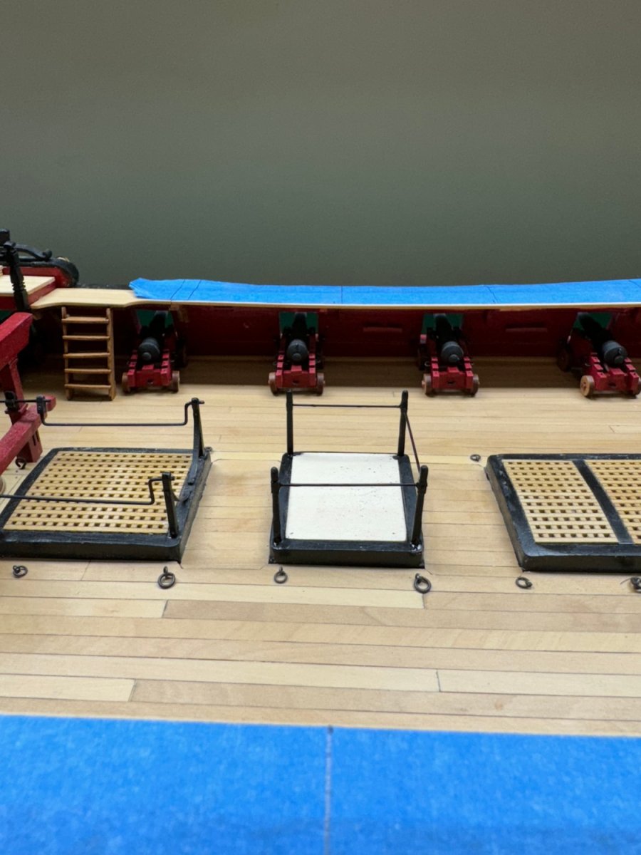
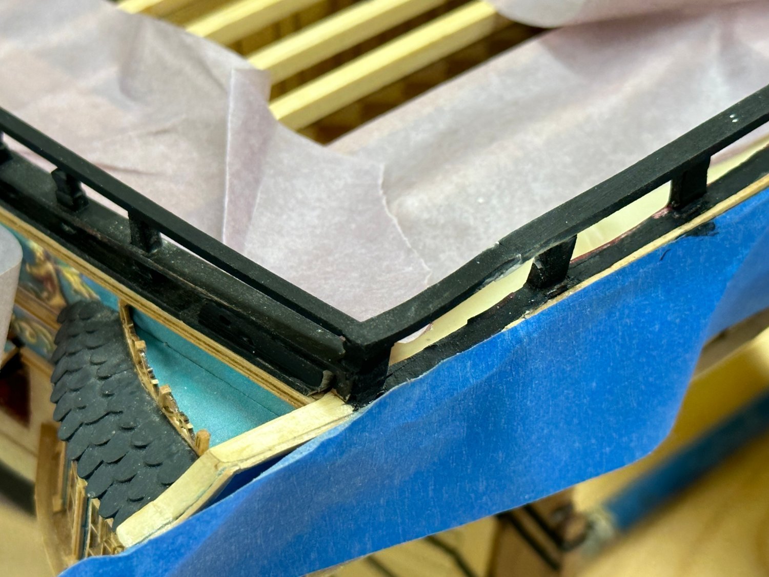
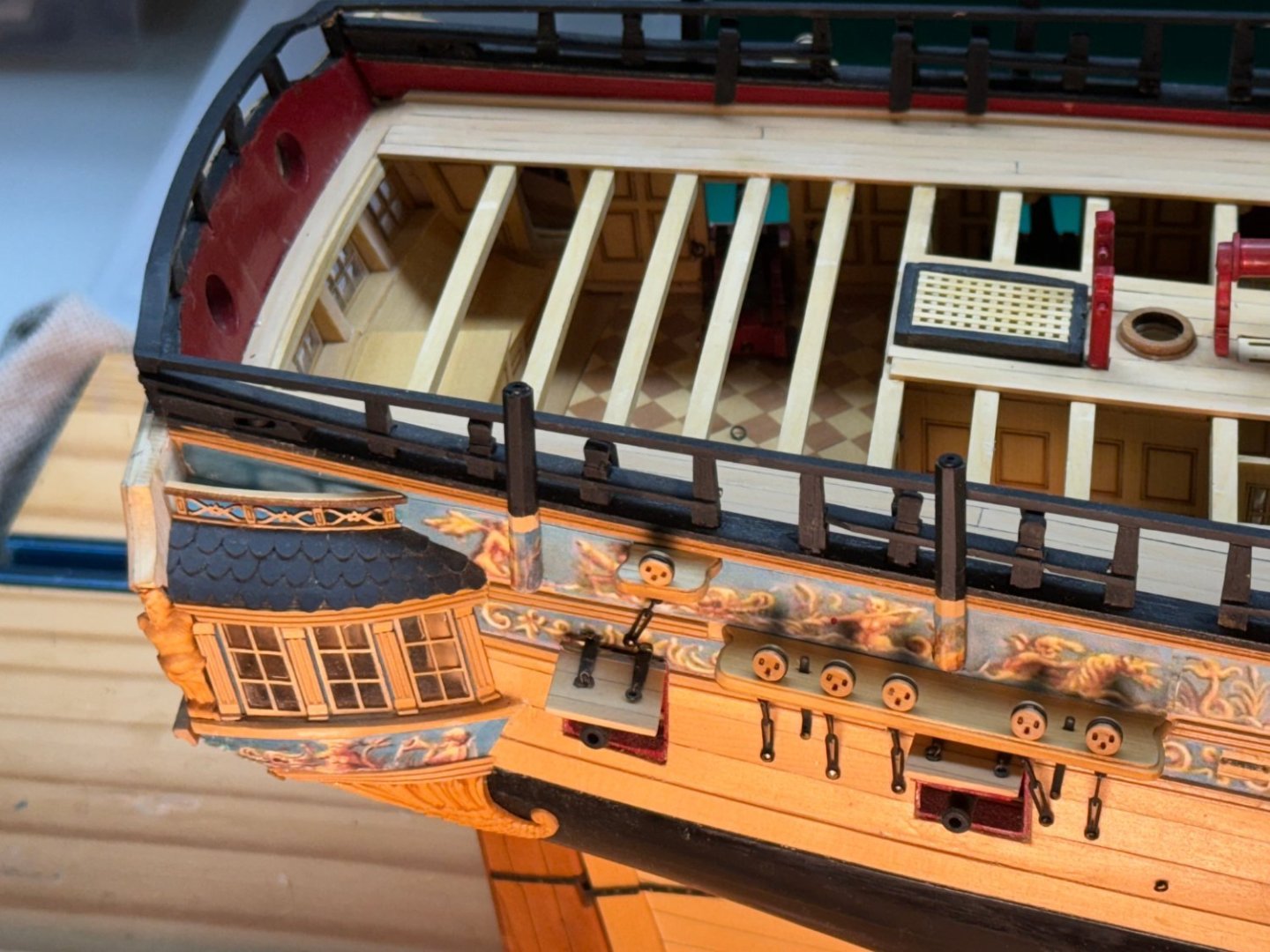
For some reason that I cannot recall I decided early on to include a ship's boat on the deck on my model. I already have the long boat built (from the Model Expo 18th Century Long Boat kit) but now need to add the deck beams that will carry it. Luckily the drawings show these deck beams so I did not have to guess where they went. I had extra cherry deck beams since I used both cherry and AYC deck beams. So I carefully laid two pieces of masking tape on the workbench and marked where the beams should go according to the drawing and where the aft end of the walkway planking should be.. I used a small square to make sure the lines were perpendicular to the tape. I put the tape on the walkway and had to move one side just a little bit (like 1 mm) so that they "looked" perpendicular to the centerline. Here are the beams just sitting on the walkway. I am going to drill a small (.025") hole in the walk way where the beam centers are and use black laser board to simulate the "crutch" that holds the beams above the walkway as shown on the drawing. I have the holes in the starboard side done now. Port side next. Oh, and I fixed the railing on the port q-gallery save some WoP. On this side the vertical pieces were still intact, just had to clean things up, add the very tender center pieces and the top rail. On the starboard side everything but the lower rail is "gone". Will require a bit more effort.

- 389 replies
-
- 5
-
-
- winchelsea
- Syren Ship Model Company
- (and 1 more)
-
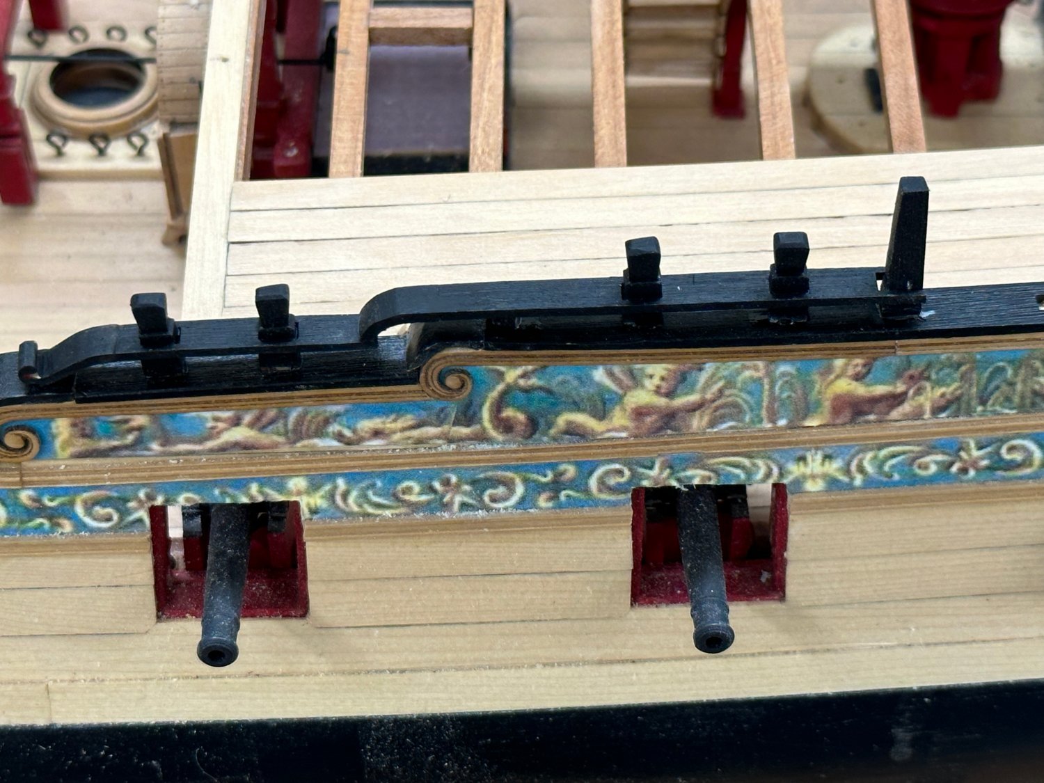
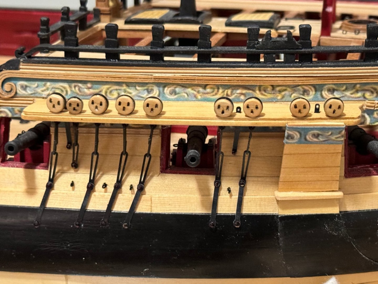
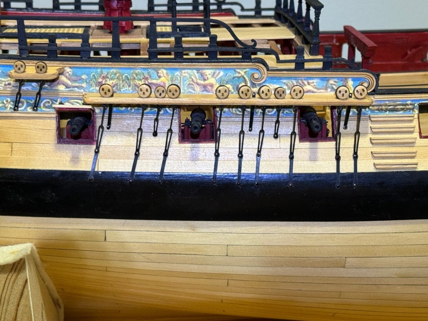
Port side Chapter 11 completed - swivel gun stanchions and newel posts and fancy railing. I will not add the actual swivel guns until everything else is complete. Too easy to snag one while working elsewhere. I decided to dispense with four of the swivel guns, the two aft of the foremast shrouds and the two in the stern. So this model will only have four swivel guns on each side. Captains choice. FYI - while working on the newel post and railing I broke the forward most deadeye - again. This time I had to replace the entire assembly. Not nearly as easy with the channel already attached to the hull but I managed. Luckily I still had a few extra deadeyes already assembled, tumbled and WoPed. Next on this side is to "fix" the railing atop the quarter gallery. I do not believe there is any more work that will endanger these rather delicate structures - but I have thought that before.


- 389 replies
-
- 9
-
-
-
- winchelsea
- Syren Ship Model Company
- (and 1 more)
-
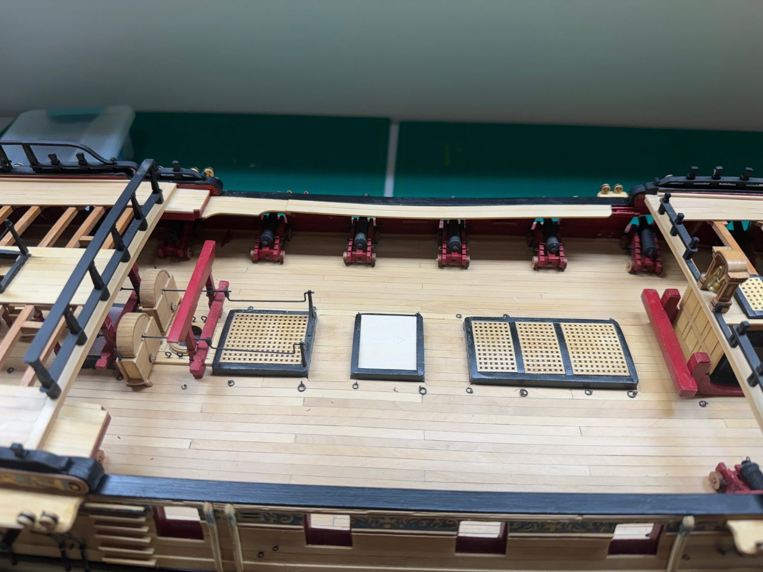
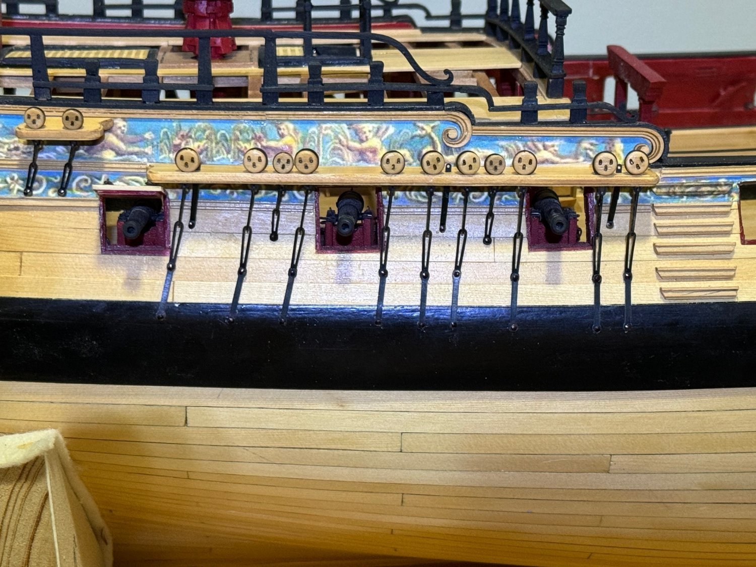
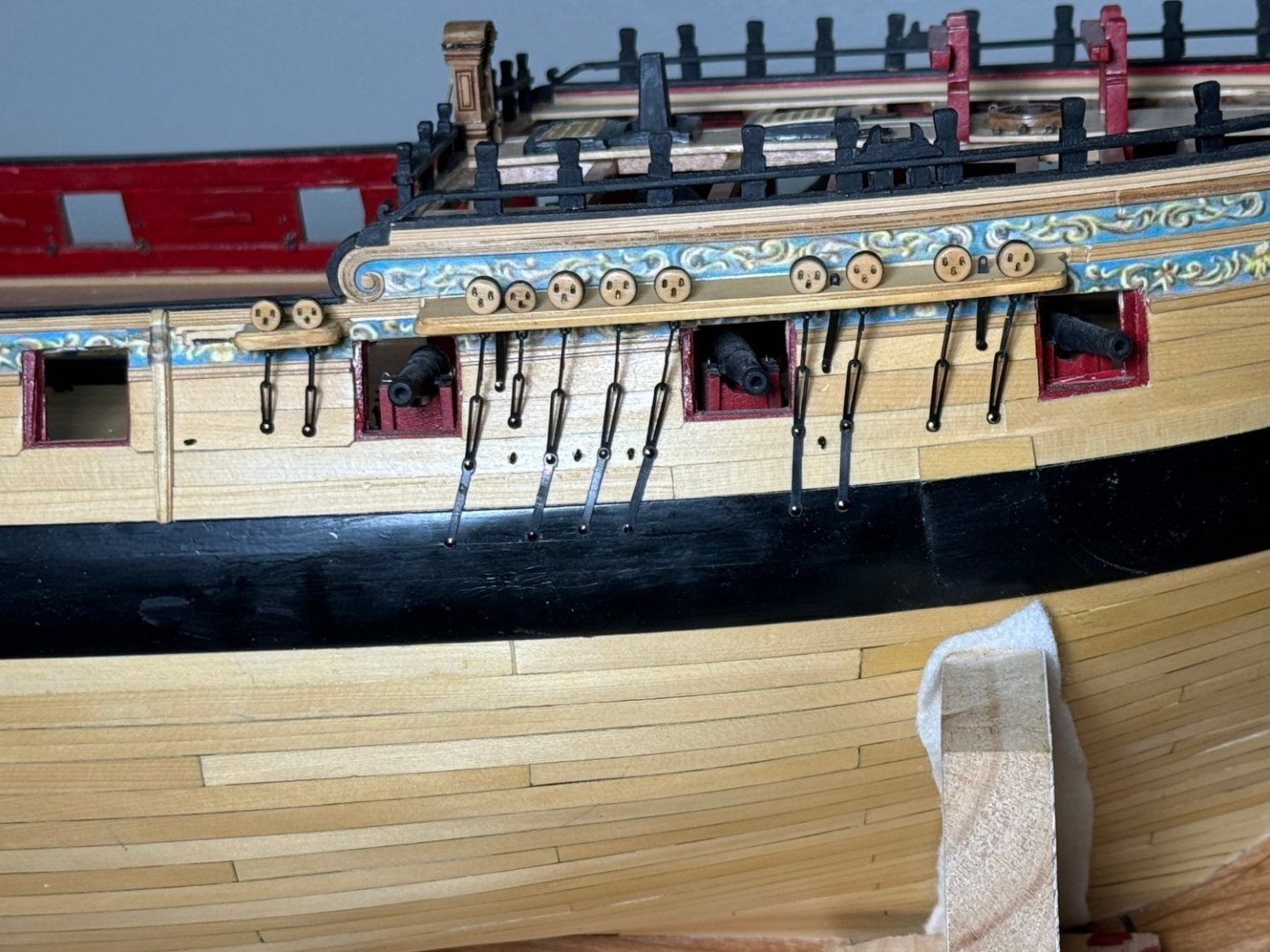
Channels, deadeyes and chainplates completed on port side. Added the gangways and decking to both sides then added the last eight cannon amidships. And yes the decking on the port side has a dip near the center. Hopefully I can "fix" this without having to redo the entire piece but if it comes to that so be it. I also upgraded the lighting in the new workshop (aka the "office" on the plans) so I can actually see what I am doing. Girlfriend offered me sunscreen when she saw it for the first time. Here are the gangways and cannon. A word of caution (don't ask me how I know this); the deadeyes are kinda fragile and can be broken off without much effort while cutting the molding for the swivel gun stands or similar task near the channels. A drop of medium CA can reattach the deadeye but depending on exactly what failed the chainplate may also require "mending".

- 389 replies
-
- 7
-
-
-
- winchelsea
- Syren Ship Model Company
- (and 1 more)
-
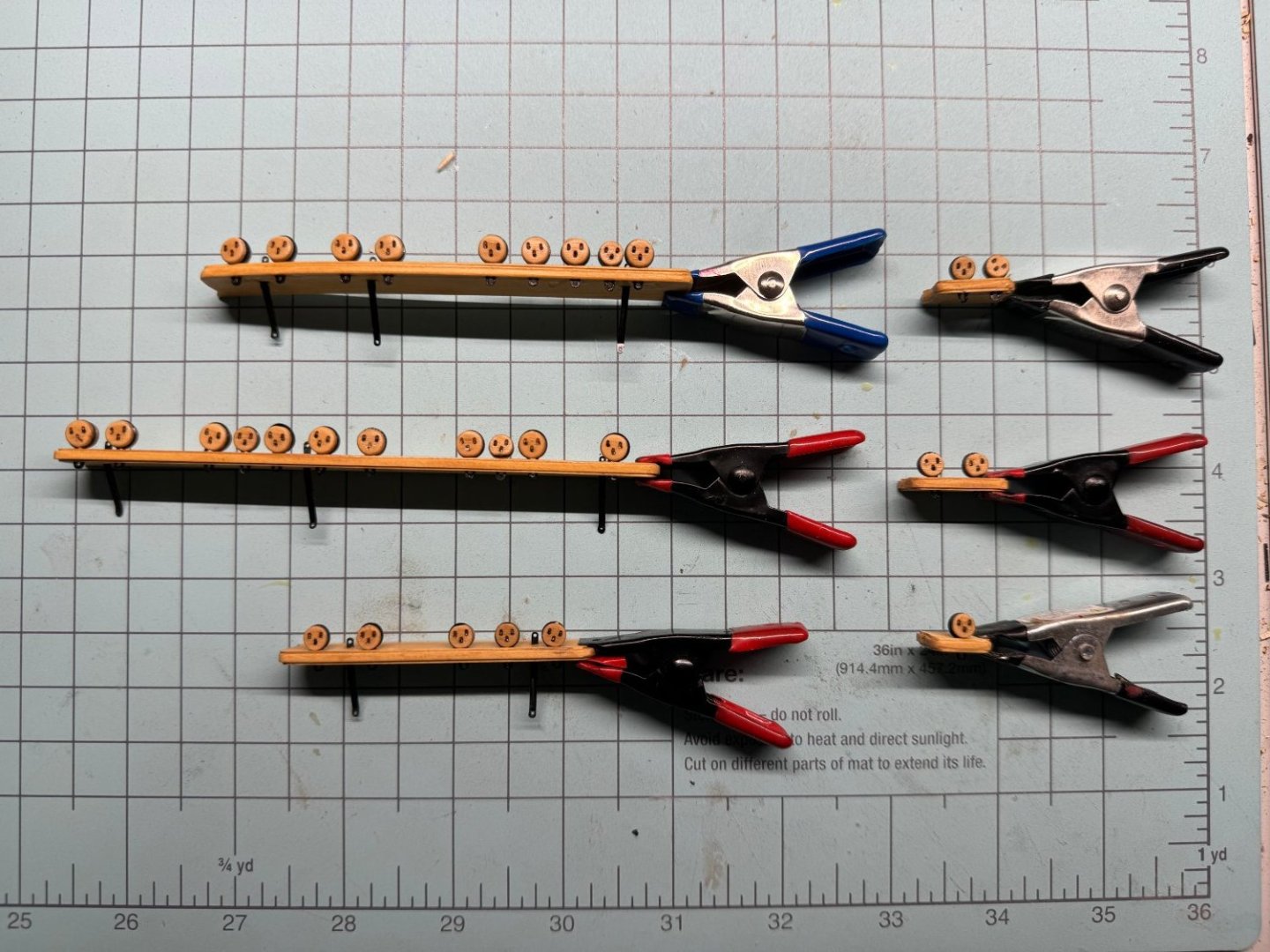
For the port side I decided to prepare all the channels with the deadeyes and chainplates before gluing the channel to the hull. I will also check the channel alignment with the associated gun port to make sure the chainplates do not interfere. A lesson learned from the starboard side where I cut out the fancy molding based on the drawing. I also put a drop of thin CA on each deadeye to keep them in the correct orientation and attached to the channel while I attach the chainplates. Another lesson learned from the starboard side - the deadeyes (some at least) would fall out of the channel when I was maneuvering it around to get the chainplates attached. A word of caution though - once the deadeye is glued into the channel and it gets broken off somehow (don't ask me how I know this) getting the remnants of the strop out of the channel can be challenging. A very fine set of needle files comes in very handy. Anyway where the port side channels with deadeye ready for chainplate assembly.
- 389 replies
-
- 4
-
-
-
- winchelsea
- Syren Ship Model Company
- (and 1 more)
-
Starboard side billboard installed. On to the port side after some workbench clean up and material restowing - also need to fix the qdeck railing where it was damaged during the mizzen channel installation.
- 389 replies
-
- 4
-
-
-
- winchelsea
- Syren Ship Model Company
- (and 1 more)
-
Looks really nice Frank. A level of craftmanship we can all aspire to.
-
Starboard side forward chesstree, eyebolts, channels, deadeyes and chainplates completed. Need to add the billboard (WoP is drying) and then on to the port side. FYI, not trusting myself with a paintbrush in the confined spaces I used a Sharpie to blacken the heads of the brass nails. Some took two "coats" but still easier (IMHO) than trying to paint them.
- 389 replies
-
- 4
-
-
-
- winchelsea
- Syren Ship Model Company
- (and 1 more)
-
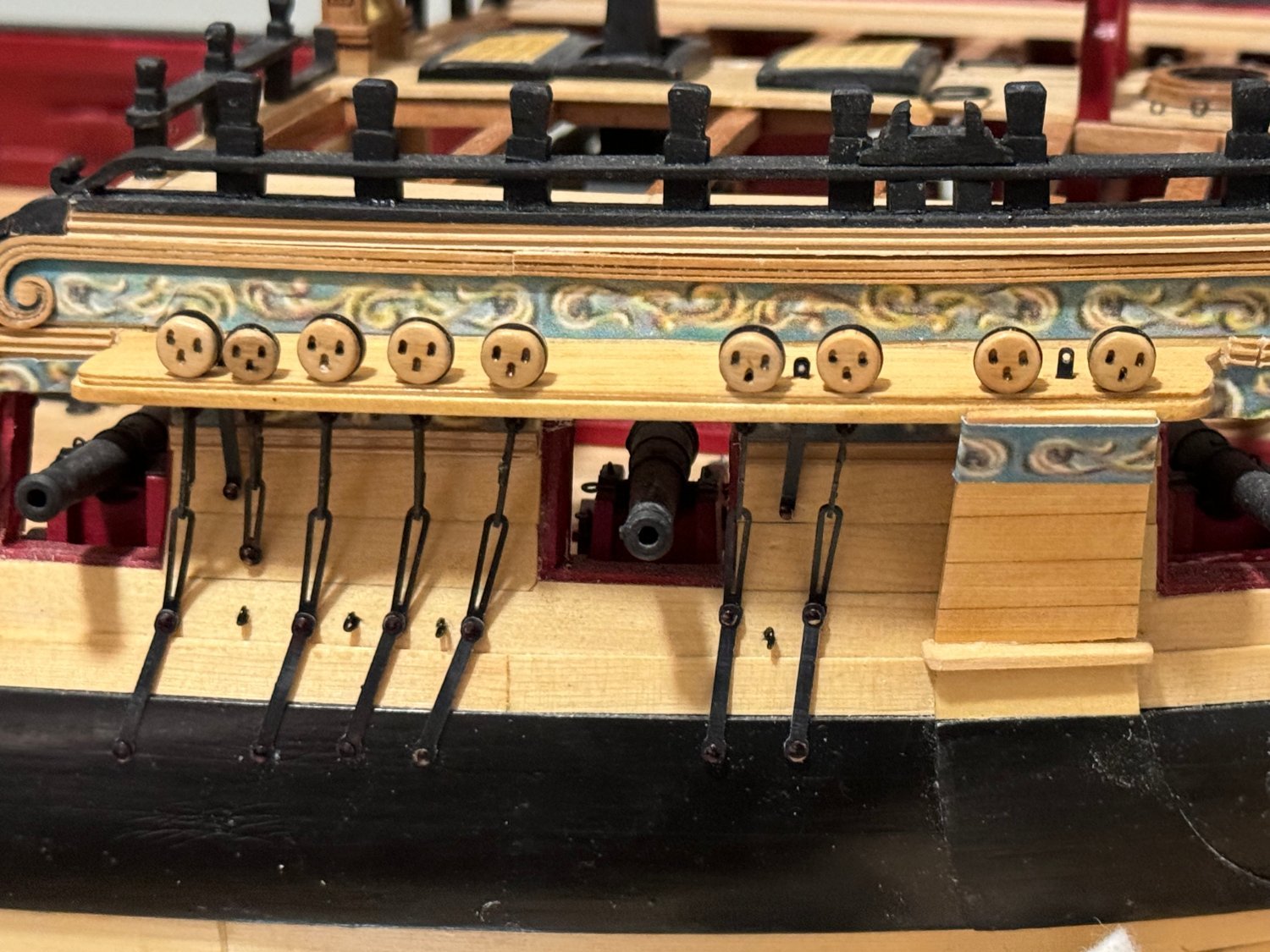
Thanks Chuck - new workshop is working okay, at least for now. Starboard main channels, deadeyes and chainplates completed.
- 389 replies
-
- 2
-
-
-
- winchelsea
- Syren Ship Model Company
- (and 1 more)
-
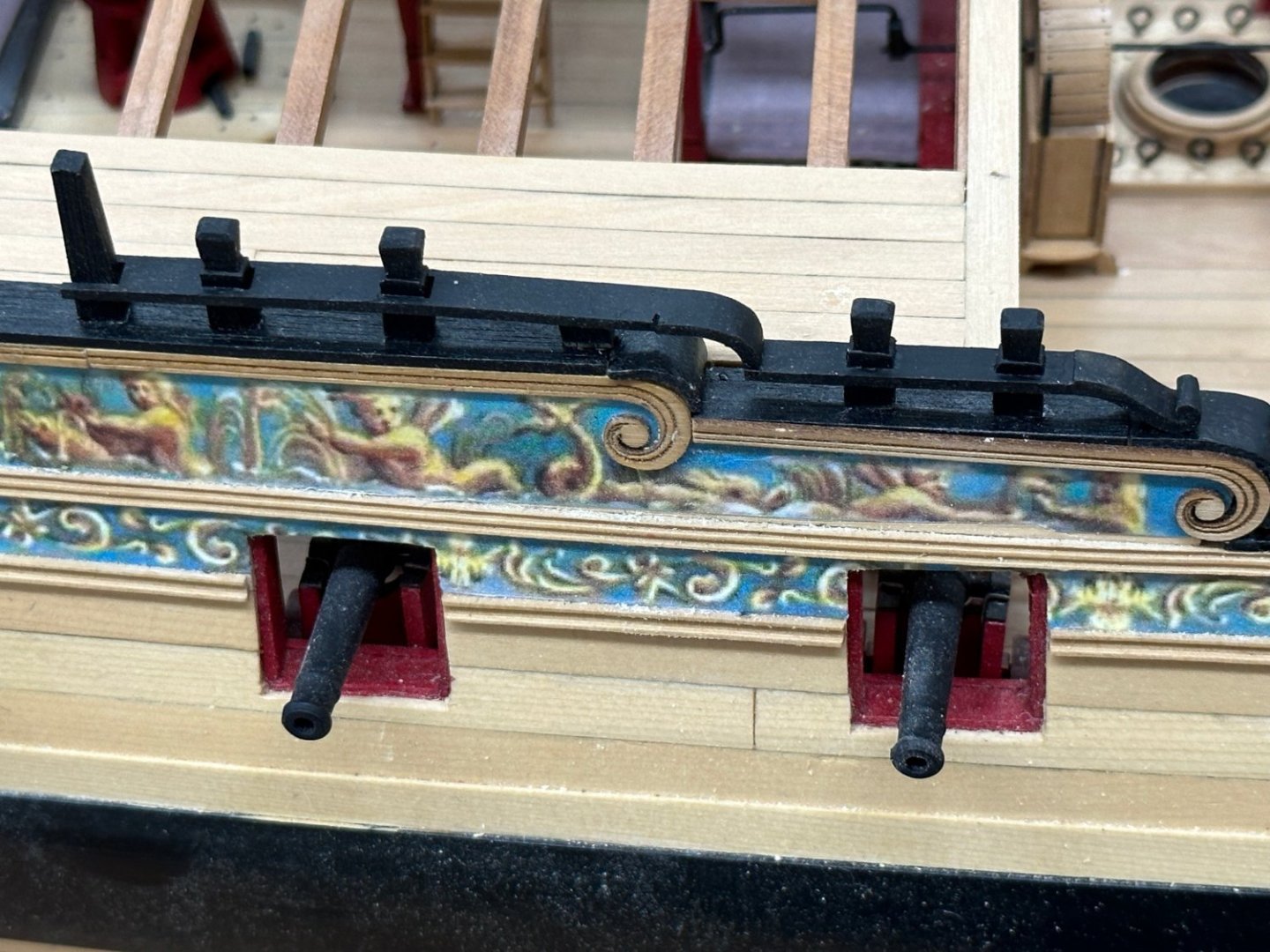
I also got the boarding "ladder" and the fenders installed. I have not yet got the molding between the fenders replaced. I used two different profiles for the upper and lower fancy moldings and can't find any scraps of the lower so will have to make some more. I originally used frieze on copy paper on the fenders and the top step but it seemed to "stand-out too much. It drew my eye to that feature rather than seeing the "whole ship". After some trial and error I finally managed to print the frieze on some silk span that I had from my days making sails. It seems pretty close to the "tissue paper" mentioned in the monograph. Of course some of the ink jet ink leaks through the silk span so you not get as opaque a frieze as with regular copy paper. It turns out IMHO that the silk span's reduced level of opaqueness helps the fenders to blend in with the frieze behind it. Will work on the chesstrees after I finish the main channels/chainplates.

- 389 replies
-
- 4
-
-
- winchelsea
- Syren Ship Model Company
- (and 1 more)
-
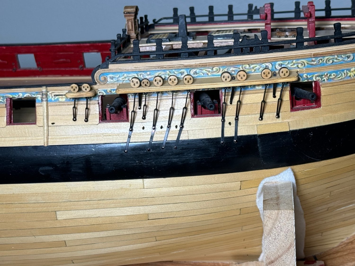
Starboard side mizzen channels and deadeyes complete. Word to wise, do not cut out the fancy molding based on the drawing alone- don't ask me how I know but it is possible that your model and the drawings do not match exactly. The middle two deadeyes on the mizzen channel should fall on either side of the gun port below. I had to move the channel forward about 1/8" to make that a reality. Otherwise the there will be no place to attach one of the chainplates. I should have moved mine over another little bit to get the chainplates on each side to be more or less vertical. The forward one has to angle forward to clear the gun port. I will be more careful on the port side. And yes I see that the qdeck railing has come adrift - was trying to make a jig to hold the mizzen stool in position while glue dried - used medium CA instead of PVA but still managed to damage the railing in the attempt,
- 389 replies
-
- 3
-
-
- winchelsea
- Syren Ship Model Company
- (and 1 more)
-
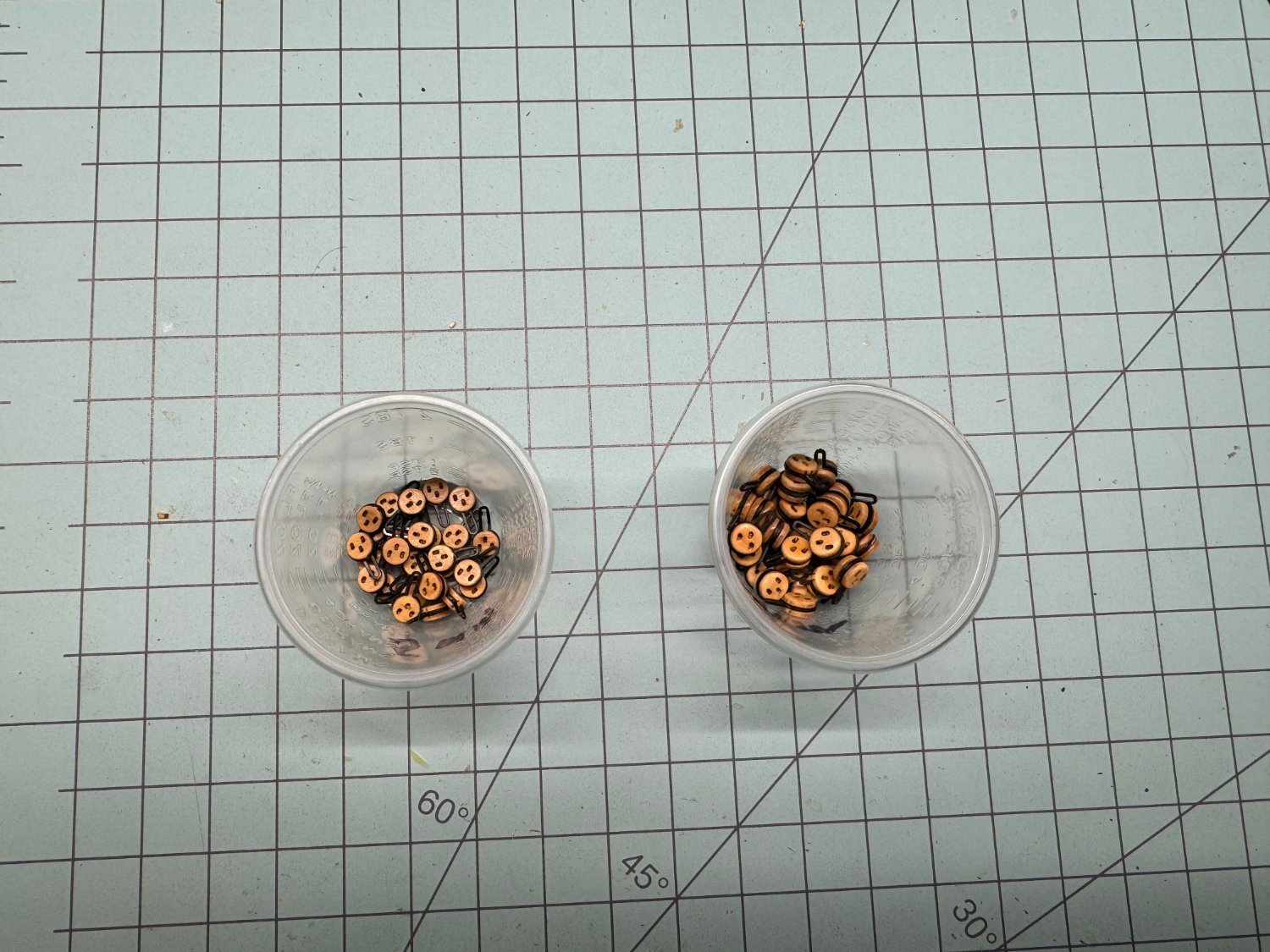
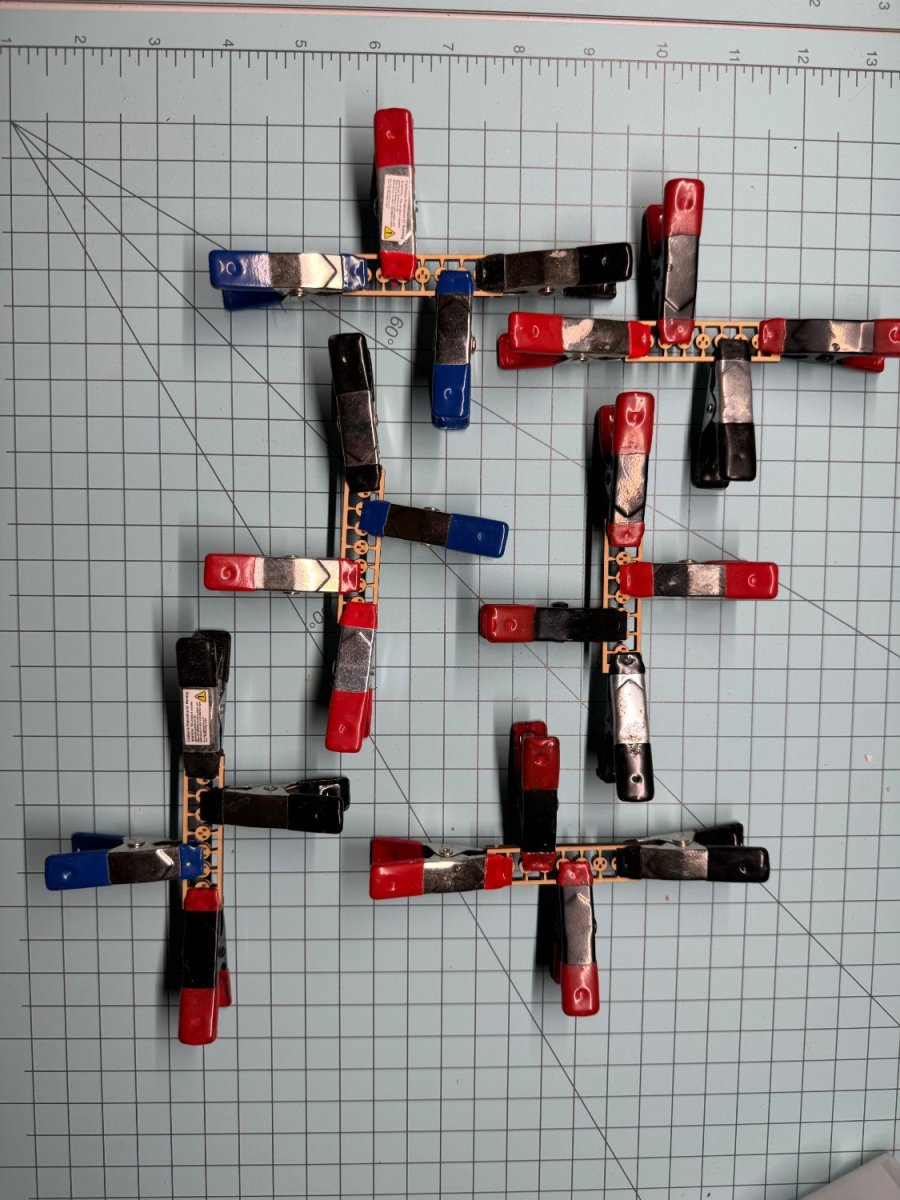
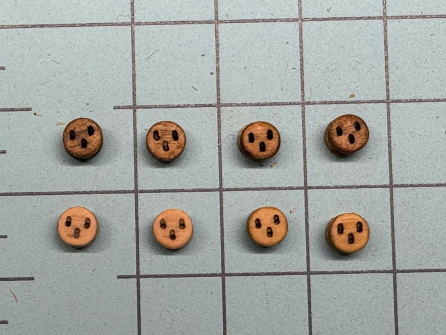
After much hemming and hawing using stain, dye and WoP I finally decided to go with the natural finish deadeyes. Getting the vinyl strops was more of a struggle than I had imagined, especially for the 6mm ones (somewhat counter-intuitive since they are the larger). Luckily I had two sets of the vinyl hardware so the fact that I broke 15 or so of the strops trying to get them around the deadeye was not a complete disaster. Anyway here they are ready for installation on the channels.

- 389 replies
-
- 4
-
-
- winchelsea
- Syren Ship Model Company
- (and 1 more)
-
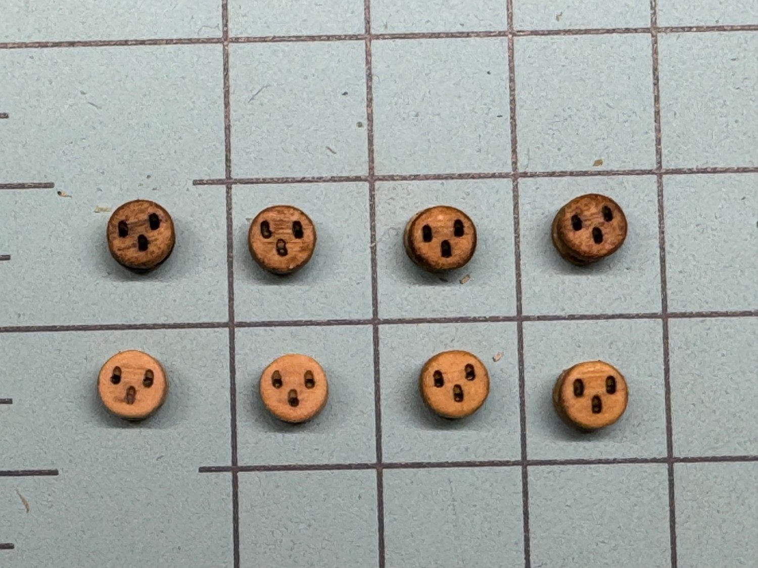
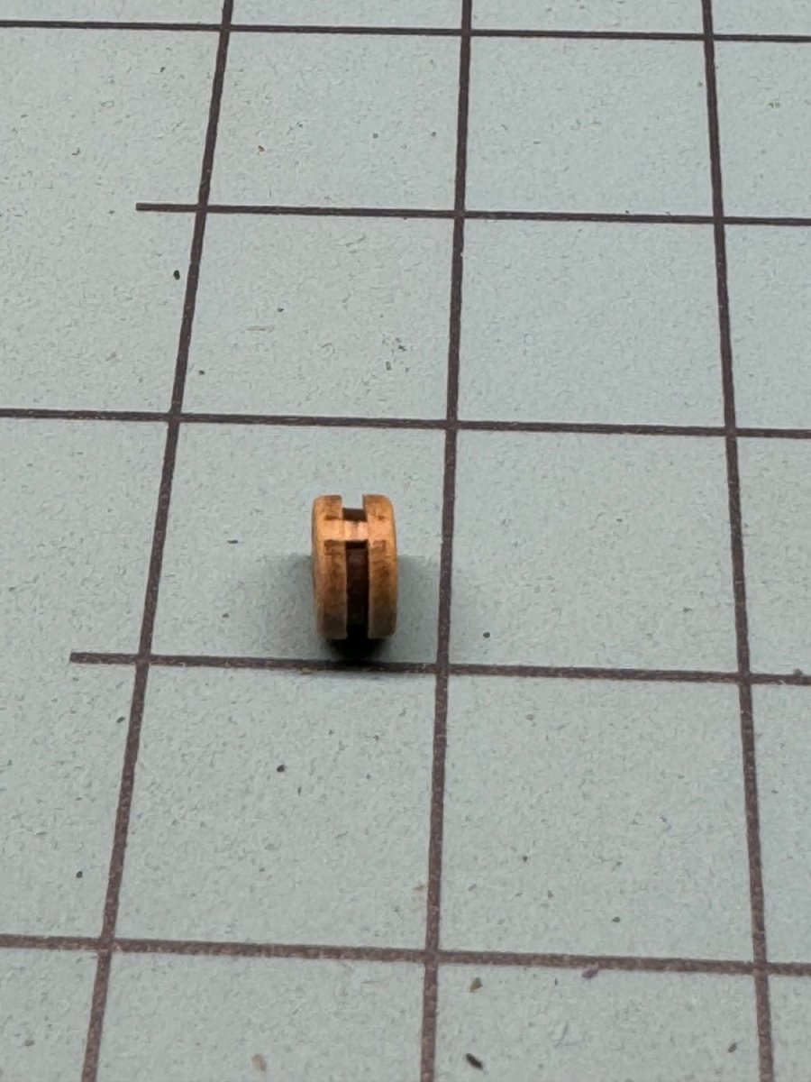
I used the Syren "you assemble them" deadeyes in the suggested 65 and 6mm sizes. I also used the "block shaper" to "take the edge off. Unfortunately the block shaper does not remove the "bridge" between the outer shell and the inner piece. See photo below: And this is one of the "better" examples. I decided that since one side will be against the channel I only had to remove this on the upper side to avoid having the strop rise above the surface of the deadeye at the top where in would be the most noticeable. So I used a very small needle file to remove the bridge on the upper side of the dead eye (the side with two eyes). Now that I have done all that it occurs to me that one way to avoid this "extra" work would be to cut the upper side of the connector on the carrier sheet of the center layer before gluing the three carrier sheets of deadeye layers together. Okay, maybe next time. The monograph says that the deadeyes were "dyed" brown. Chuck says to use fiebings leather dye, medium brown. I will have to acquire some but in the meantime I tried stain. In the photo below there are two examples of each stain I have in my "stain locker". The upper row (left to right) is two using walnut and two cherry - the bottom row is two unstained and two honey. The walnut might work if the leather dye turns out to be "too hard" - Chuck warned that it will dye anything it touches.
- 389 replies
-
- 5
-
-
- winchelsea
- Syren Ship Model Company
- (and 1 more)
-
Frank, Thank you and I hope your and your family have a safe and joyous holiday seasoI will be back to the Winnie when my holiday guests go home - which is tomorrow..
- 389 replies
-
- 1
-
-
- winchelsea
- Syren Ship Model Company
- (and 1 more)
-
While waiting for the turkey to cook I started working Chapter 11. I started by assembling the 5mm deadeyes while I await delivery of the Scotch Spray Mount Artist's adhesive for the channel assembly. As it turns out I needed another set of the 6mm ones to have some spares and I decided to order the cherry material for chapter 11 as I may decide to do the channels in cherry for some additional contrast. I will likely assemble both the cherry and boxwood (or maybe they are AYC) channels and then decide which to use. I need to go baste the turkey so that this will be as far as I get today - food and football to follow.

- 389 replies
-
- 4
-
-
- winchelsea
- Syren Ship Model Company
- (and 1 more)
-
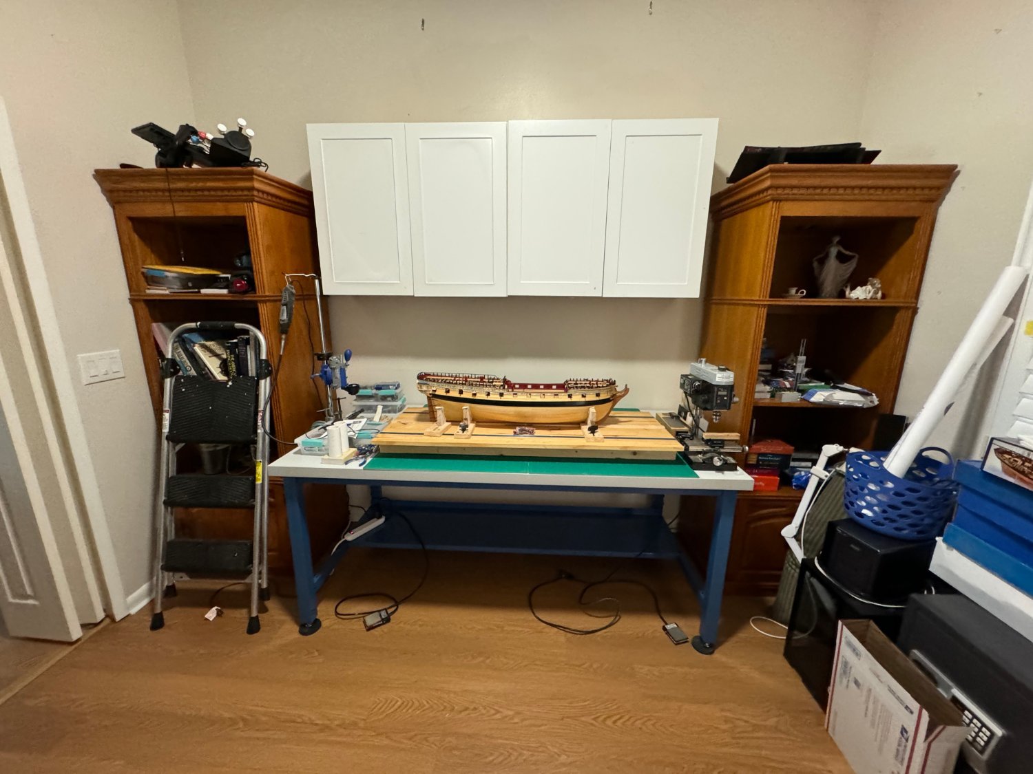
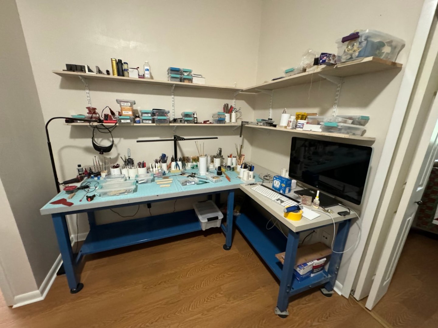
It took longer than I had thought (doesn't everything?) but I have finally gotten at least the inside portion of the workshop relocated. I will really miss the 400 sq ft dedicated workshop I had at the old house but once I get a part of the garage climate controlled I think this will work out. The plan is to have the power tools (Sander, table saw, etc.) in the garage to keep the dust and debris level down in the house. I also am moving the wood storage to the garage so there will probably be more trips to the garage then before but I really need the exercise - while moving is stressful, eating as a stress reliever has its drawbacks. Having seen what others have for work spaces I am grateful to be able to devote this much space to model shipbuilding.

- 389 replies
-
- 9
-
-
- winchelsea
- Syren Ship Model Company
- (and 1 more)
-
I think this is the end of Chapter 10 - and not a moment too soon. I have decided to not plank over the "Great Cabin" as I am still considering adding some furniture there. All I have been able to find in 1/48 scale is doll house items some of which (table and chairs) may be "okay" but everything else I have found is either plastic or not the sort of thing you would find in this space. Last post until sometime later this year after I get a workable arrangement in the new house to allow me to finish this job; and hopefully start a new project not related to painting or otherwise laboring on the new house.

- 389 replies
-
- 3
-
-
-
- winchelsea
- Syren Ship Model Company
- (and 1 more)
-
Thanks Fred - yes quite the "nerve shredder" although with closing on Tuesday I believe everything that needed to be done is done or is "well in hand".
- 389 replies
-
- 1
-
-
- winchelsea
- Syren Ship Model Company
- (and 1 more)
-
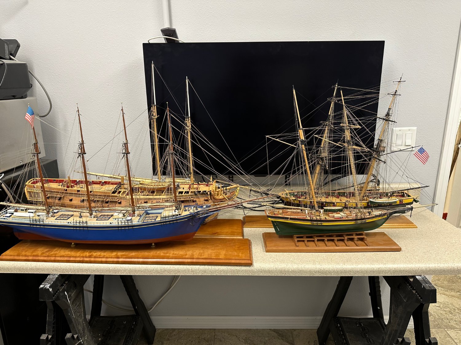
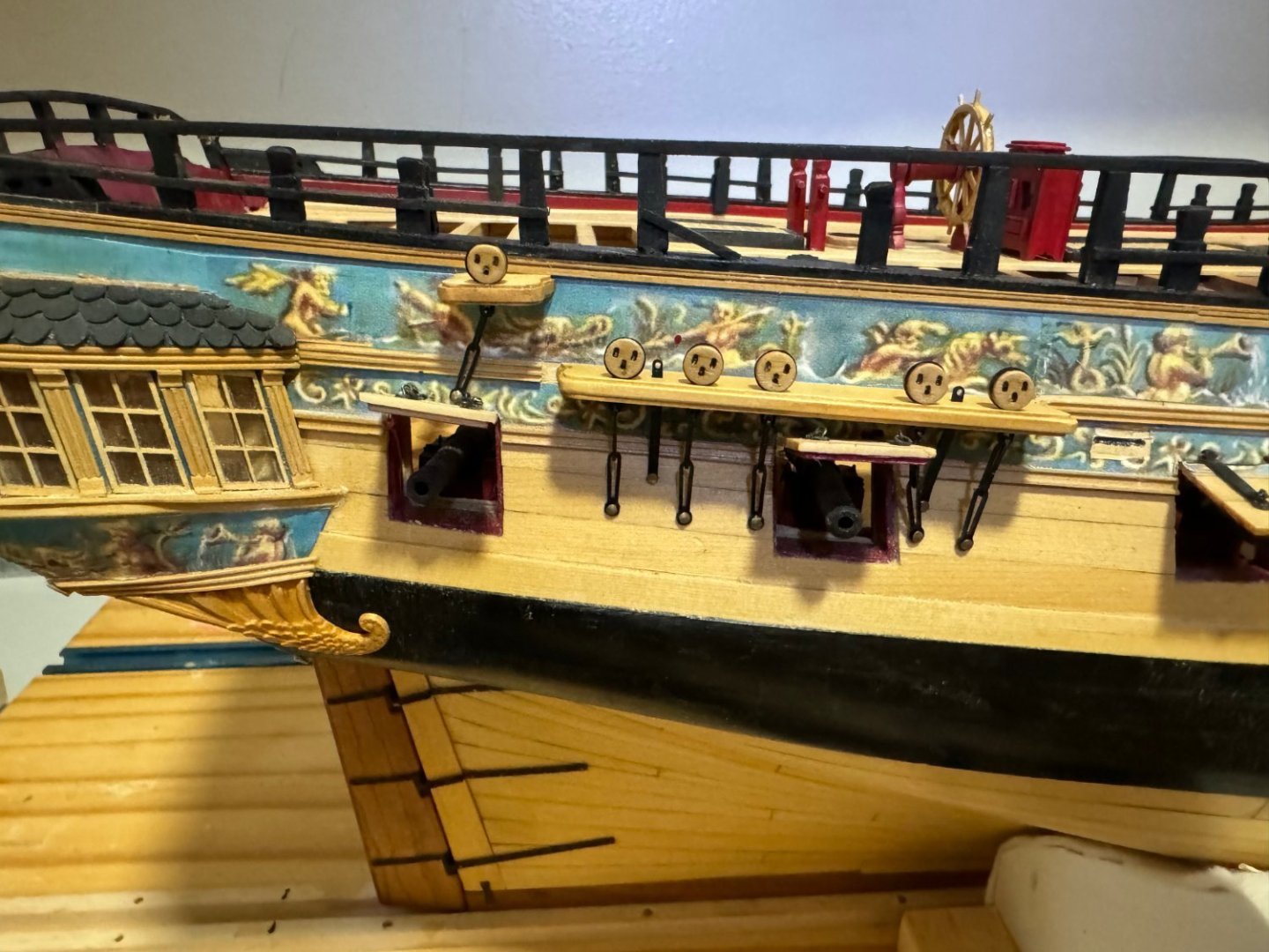
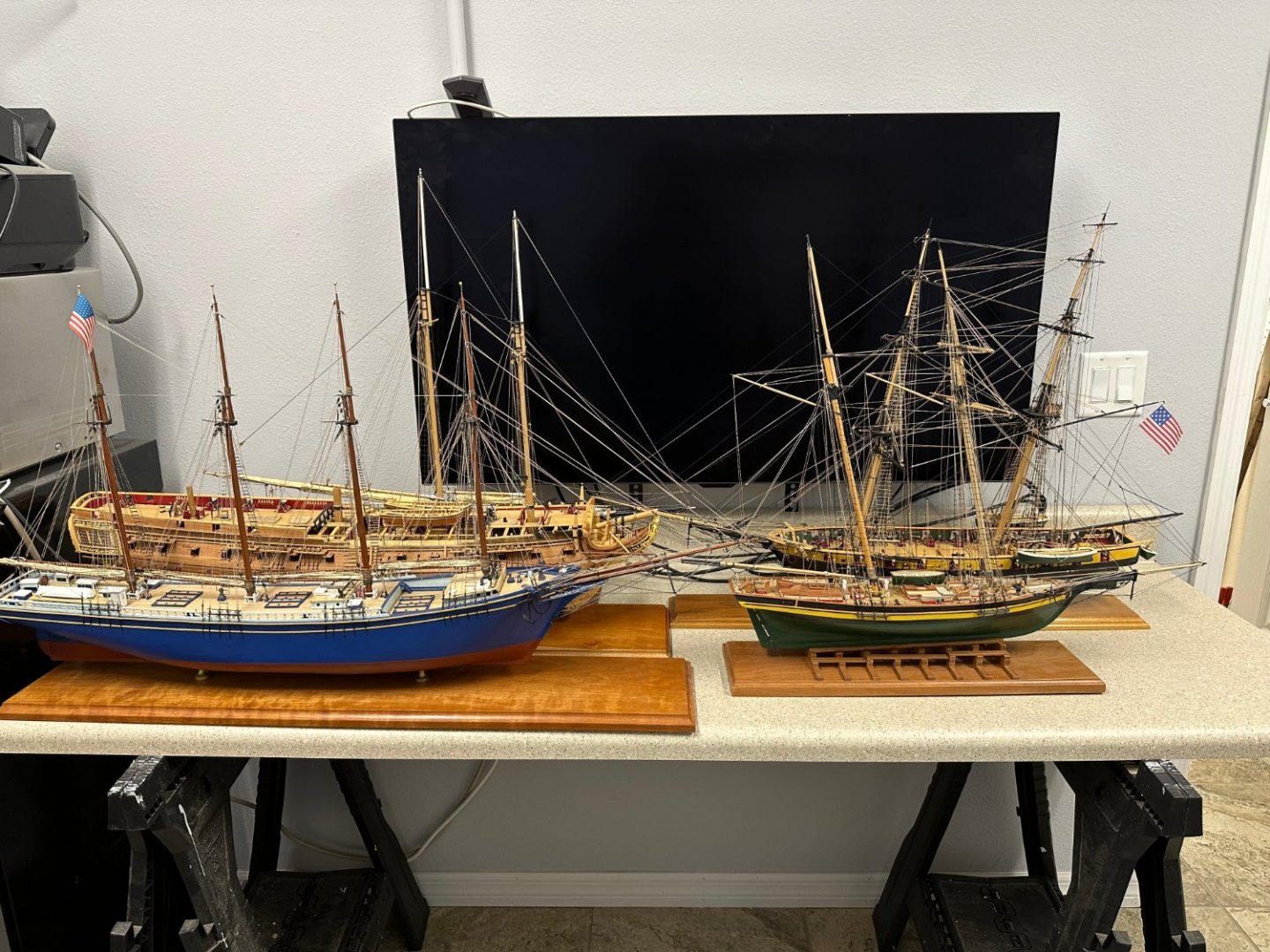
The "fleet" is in! I had to move most of the model collection out of their display cases in preparation for the upcoming move to new (to me) house. Hopefully they will be out of harms way here in the workshop when the movers come. They will be transported one-by-one (it is only 8 miles) once the new house is "settled" or at least the display cabinets are back in place as settled is probably a 2024 "event". I got the fancy molding completed on the port side, including that side of the stern transom molding absent some MORE touch-up painting - does it ever end? Hopefully the starboard side today and the six fairleads tomorrow and some more touch up painting. Then Chapter ten is done and I am off to Europe for two weeks and moving to the new house. FYI - as you can see in the picture above the quarter gallery railing did not survive the fancy railing's installation as well as one might hope. I delayed installing the q-gallery roofs until well after Chapter three (when they were installed in the monograph) but clearly not long enough. The starboard side is in worse shape so they will have to be dealt with during the Chapter eleven and twelve work.

- 389 replies
-
- 3
-
-
- winchelsea
- Syren Ship Model Company
- (and 1 more)
-
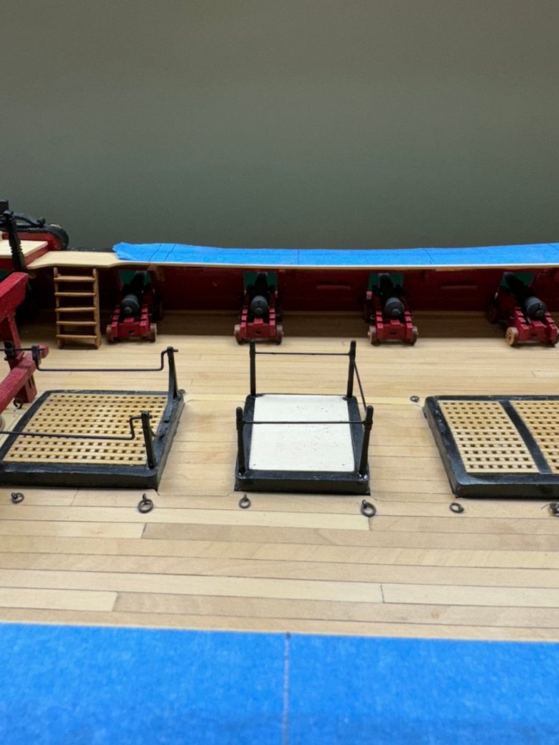
Centerline furnishings added as fancy rail (lower) is added. Masking tape is to allow for touch-up painting with less chance of getting black paint other than where it was intended.
- 389 replies
-
- 4
-
-
- winchelsea
- Syren Ship Model Company
- (and 1 more)
-
With the first three sections of the lower fancy rail in place I reconsidered my earlier decision to not "populate" the centerline features until the qdeck railing was complete. looking at the upper fancy rail I now recognize how "tender" and "in the way" that I likely to be when in place so I think I will populate the centerline pieces as the lower fancy rail is completed moving aft at the very least before the upper railing is added. Hatchway railing in place. I used 3/32" X 3/32" boxwood as the starting point. The 1/16" X 1/16" material that I have is "less than it might be with respect to dimension consistency. Besides I think I had about a 25% success rate when I used the 1/16" X 1/16" material I have. Anyway I drilled the back two stanchions all the way through in one dimension (fore and aft in this case) and then into that drill hole from the other side making a "T" shaped "passageway" through the square part of the stanchion just below the "ball" at the top. Then I used a piece of .020" piano wire to adjust the stanchions for verticality and then for alignment with the edge of the hatchway. Medium CA was used to secure the stanchion to the hatchway with a .032" "pin" in the bottom of the stanchion. The piano wire was replaced with .020" phosphor-bronze wire which has yet to be painted. I used piano wire while making the adjustments because it is much stiffer than the phosphor-bronze and much less likely to get bent or distorted with repeated handling. I would keep the piano wire but trimming it to an exact length is very difficult and likely to cause collateral damage. The other stanchions were drilled through in one dimension and a similar technique employed to get the stanchions and wire aligned. After the CA had set to hold the stanchions, I put a drop where the wire exited each stanchion then clipped the wire off flush with (more or less) the stanchion. Hopefully a coat of flat black on the wire and touch-up on the stanchions and this will be "done".

- 389 replies
-
- 3
-
-
- winchelsea
- Syren Ship Model Company
- (and 1 more)
-
The first sets of the qdeck fancy rail ion place. Things lined up relatively well although getting the short post into the "hole" in the base was somewhat of a challenge. That "hole" is made up of the junction of the first two pieces of the lower cap rail and it is possible that the opening is not as big as one might like. A word for those who build this later. If you decide to include the eyebolts for the gun carriages on the qdeck be careful adding the eyebolts as doing so makes the posts, which are already a pair based on the height (lower aft) but now are differentiated port and starboard by which side the eyebolts are placed. It is entirely possible to mess up and get the eyebolts on the wrong side - don't ask me how I know. It is probably best to dry fit the posts and mark which side the eyebolts go on BEFORE you start drilling holes and certainly before you glue any eyebolts in.

- 389 replies
-
- 3
-
-
- winchelsea
- Syren Ship Model Company
- (and 1 more)
-
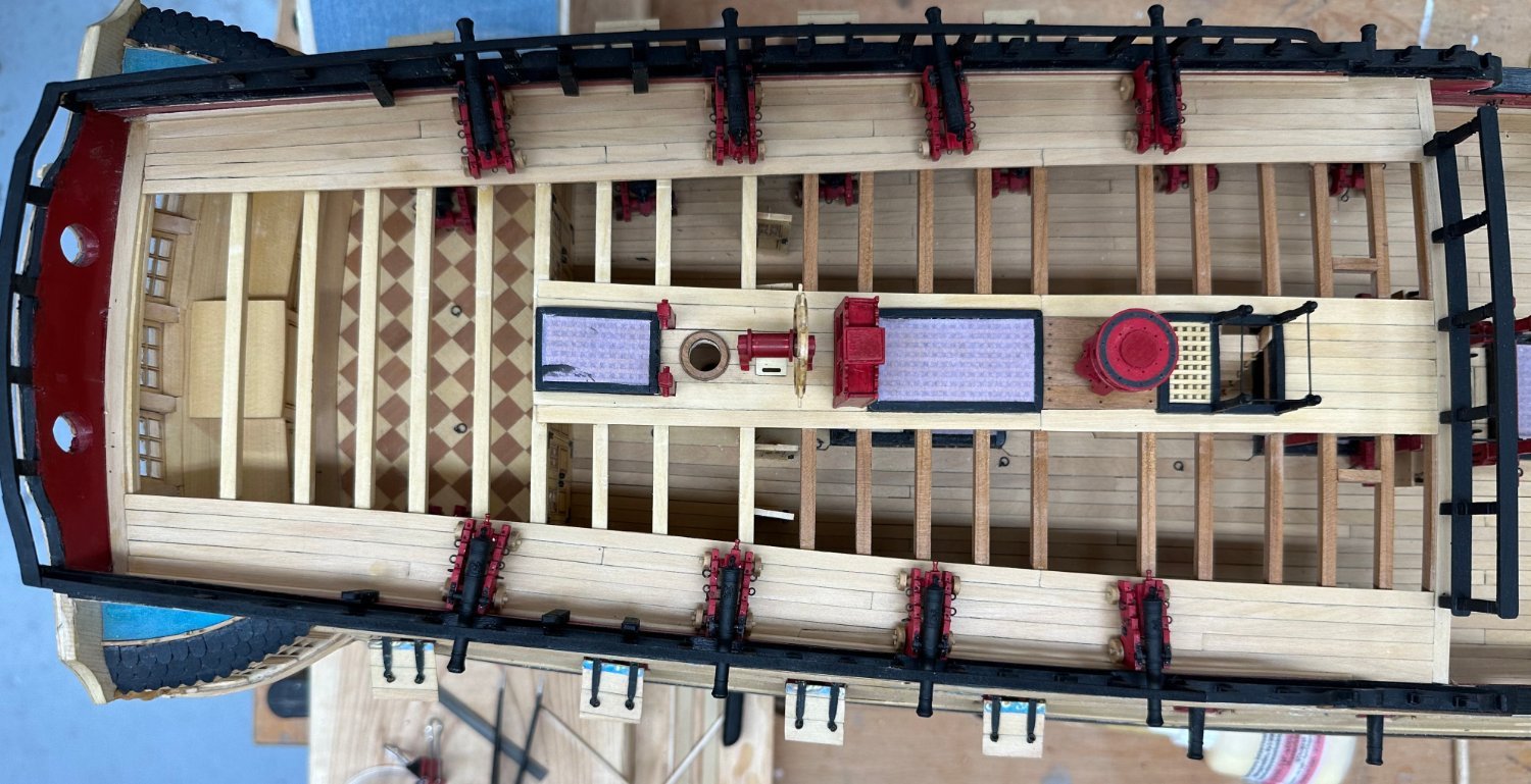
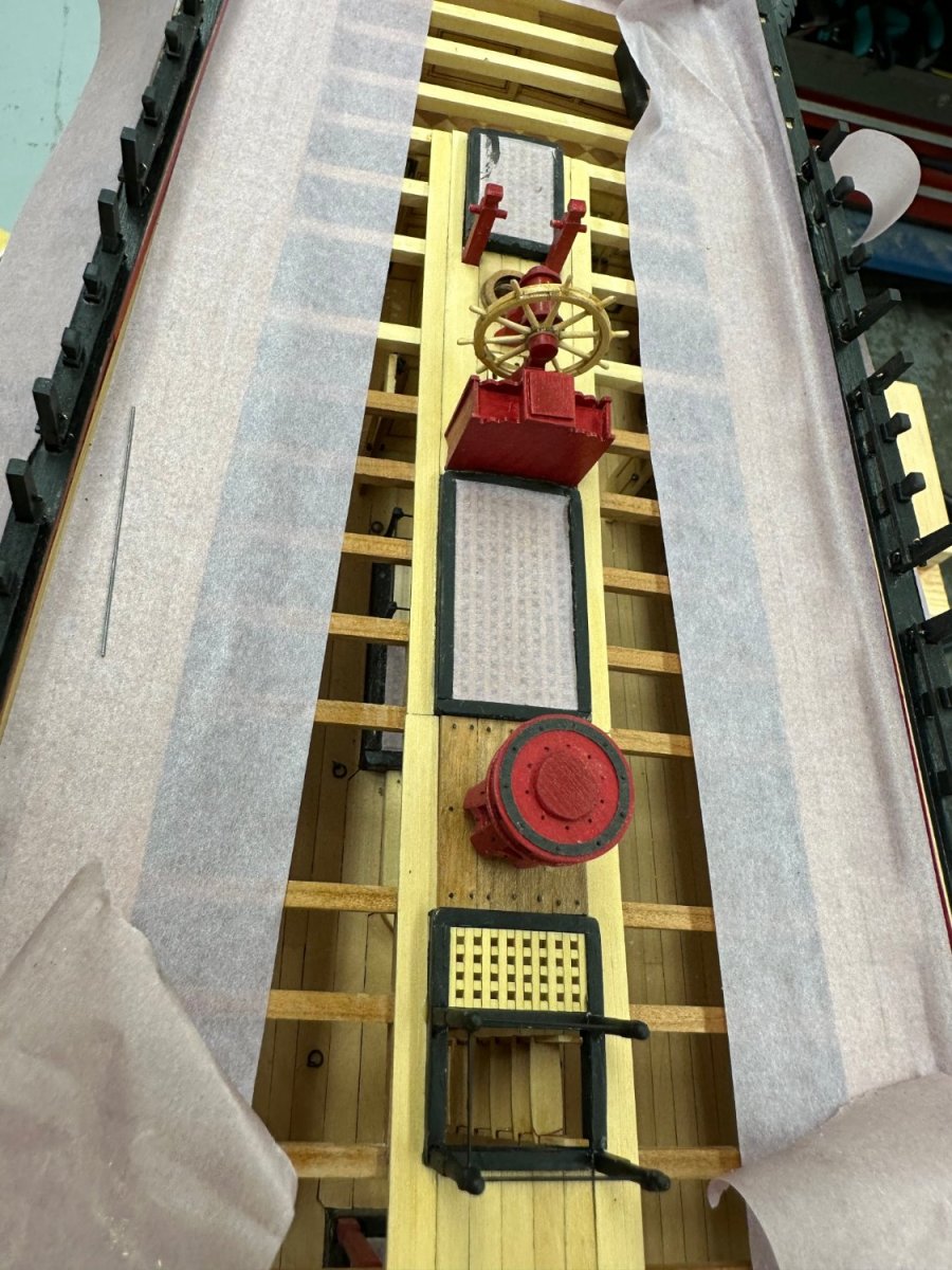
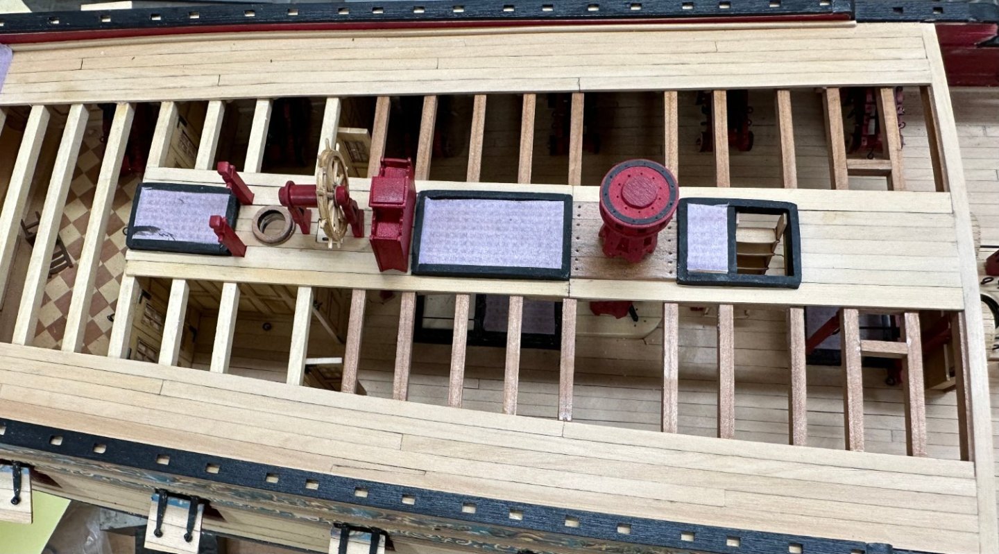
The centerline decking is complete (no WoP yet) and the binnacle, ship's wheel and capstan are in place (dry fit for now). I have the breastrail assembled and awaiting another coat of paint. I will probably not glue any of these pieces down until I have the fancy rail and transom rail done. Too many things sticking up presenting more opportunities for disaster - especially at this late stage of things.
- 389 replies
-
- 1
-
-
- winchelsea
- Syren Ship Model Company
- (and 1 more)
-
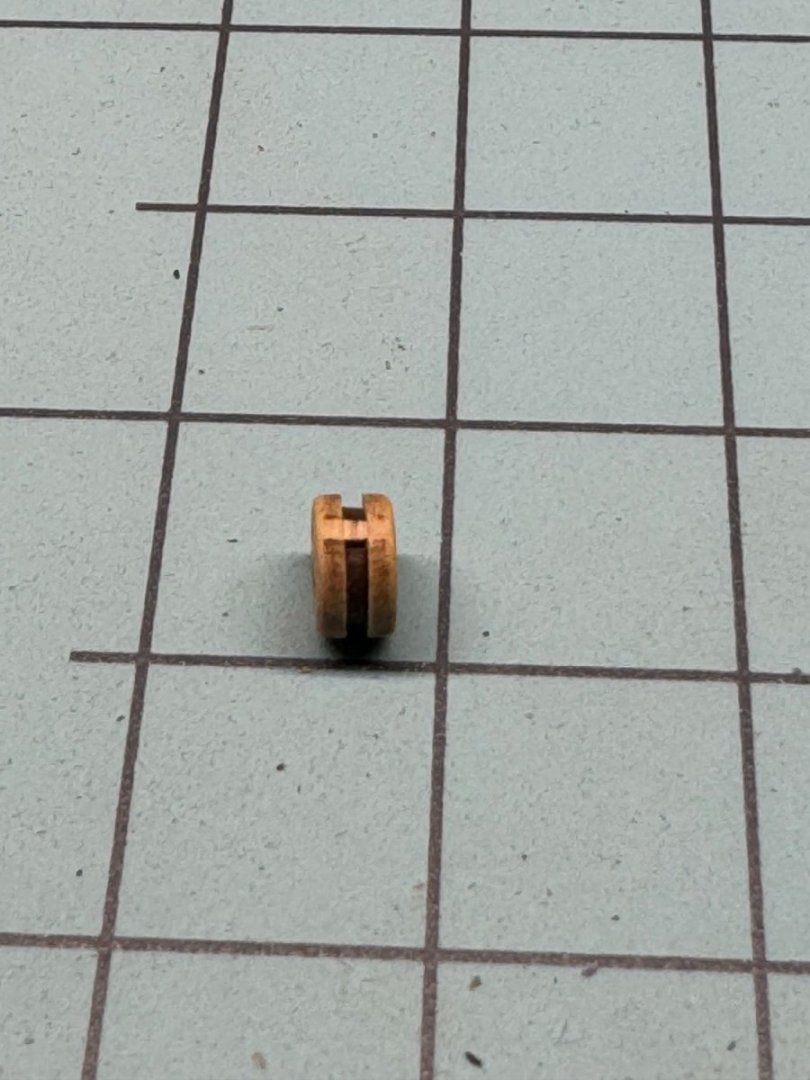
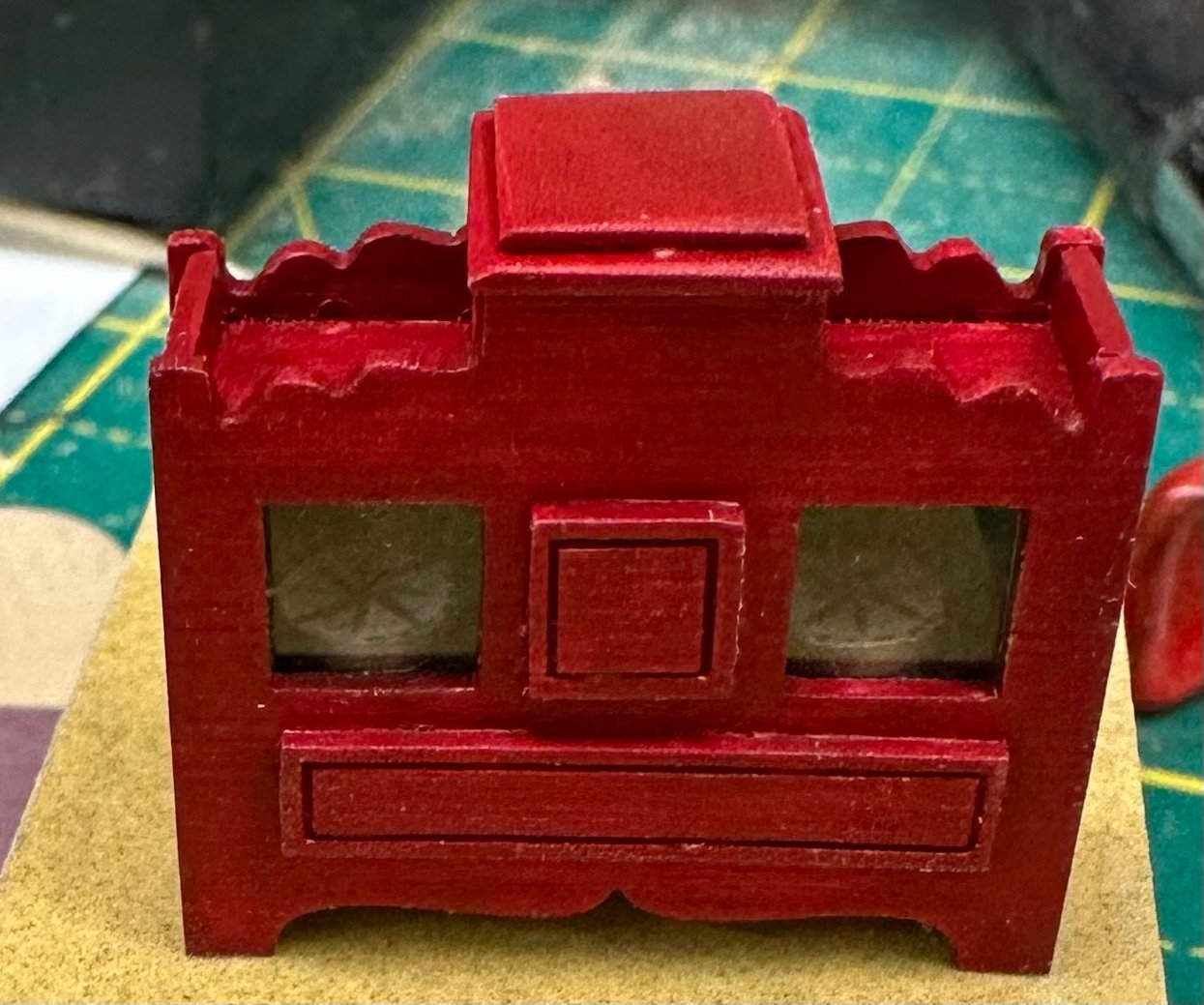
Here is my finished (except possibly for some touch up paint - it look better in "real life"). Although it is probably impossible for anyone else to ever notice but I did glue a compass rose to the two "disks" inside the binnacle. I should have painted the disk edges white too but... And now I have a .jpg compass rose image that can be printed to whatever size I might need in the future. Ships wheel is almost done so I better get busy and complete the centerline decking so I can start the qdeck railing.
- 389 replies
-
- 5
-
-
-
- winchelsea
- Syren Ship Model Company
- (and 1 more)