cdrusn89
-
Posts
1,918 -
Joined
-
Last visited
Content Type
Profiles
Forums
Gallery
Events
Everything posted by cdrusn89
-
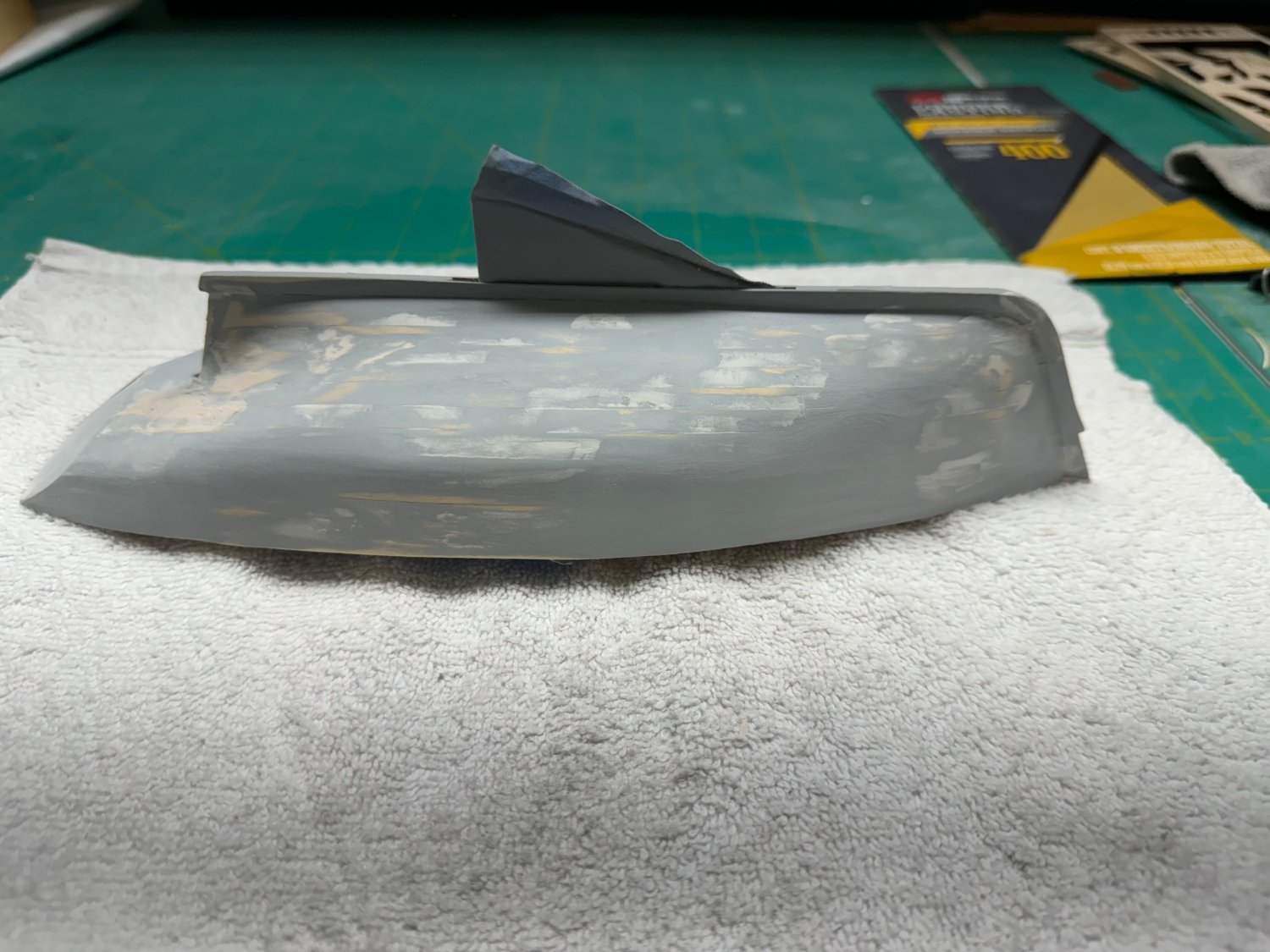
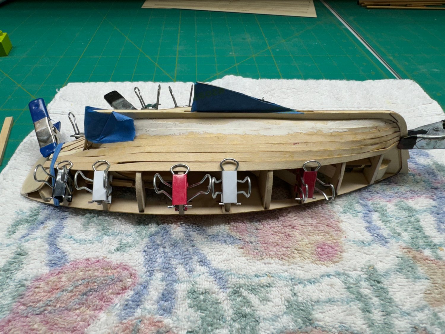
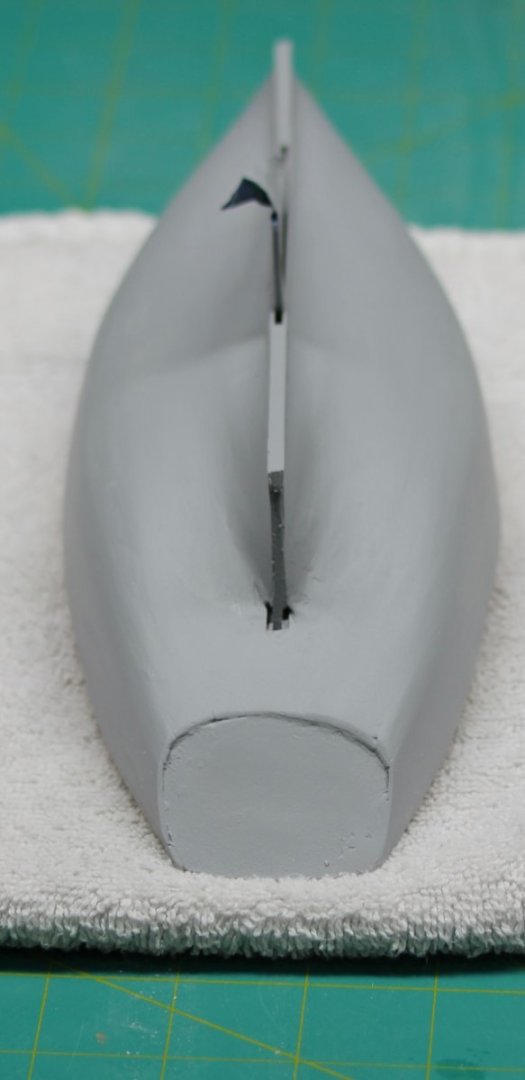
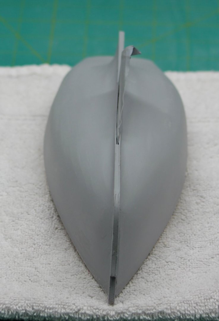
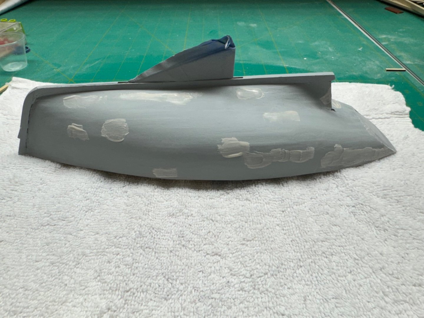
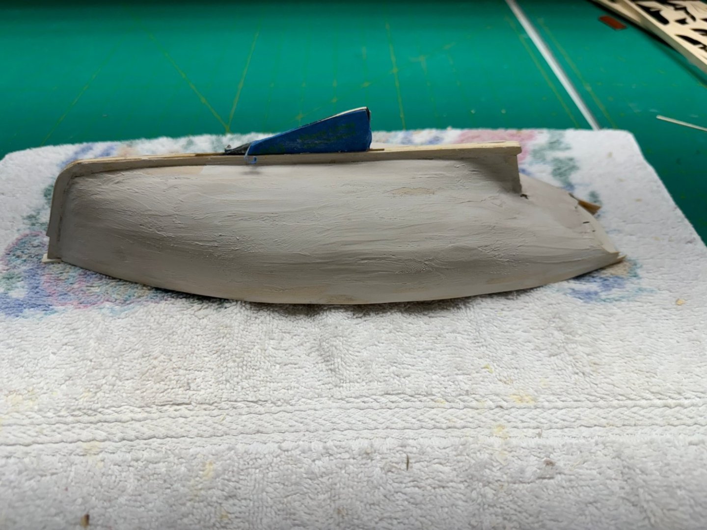
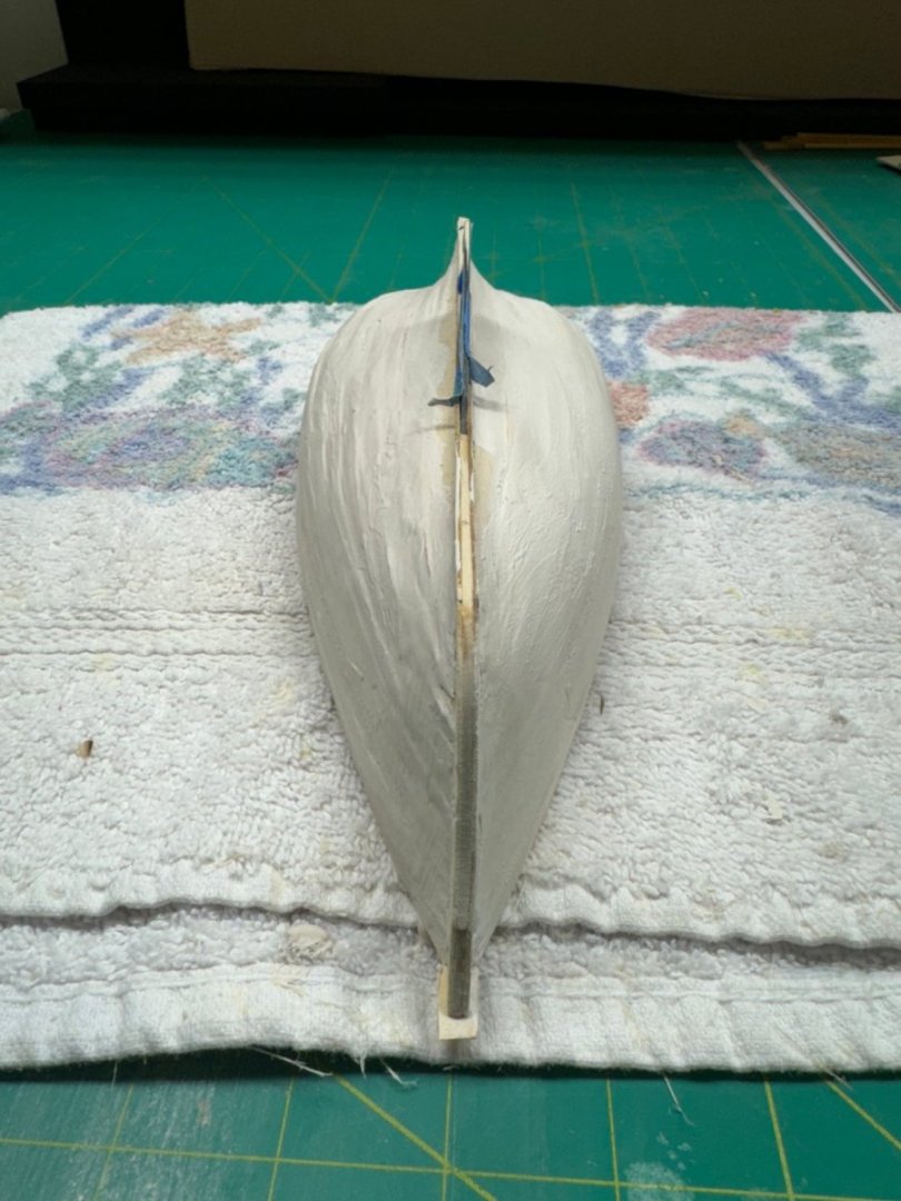
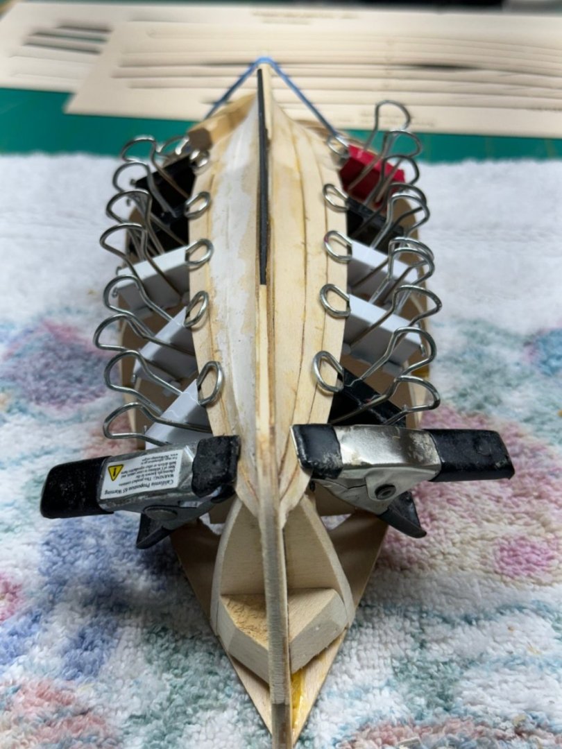
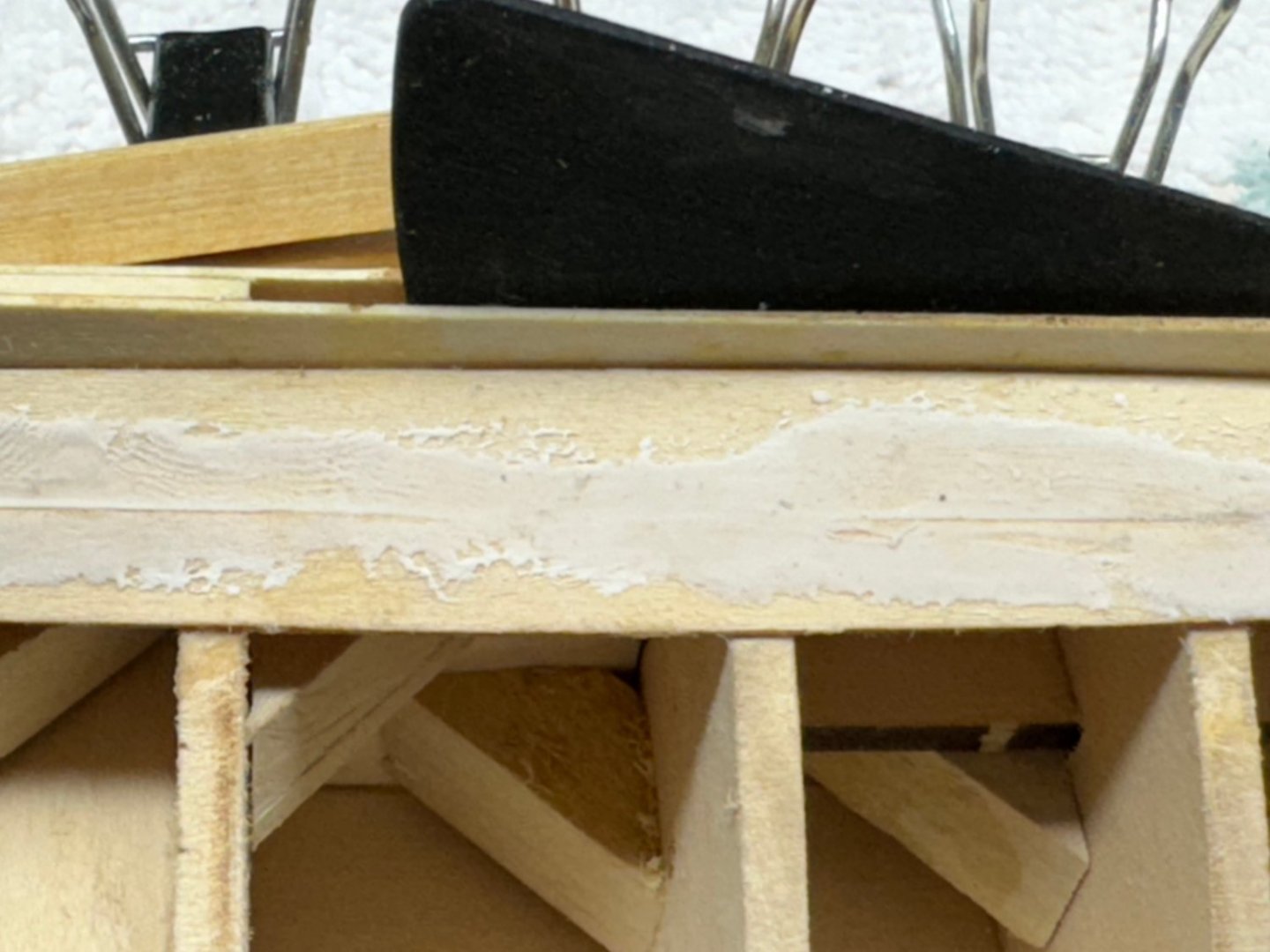
 Here is the hull after the second coat of the primer/filler but no sanding (yet). I am considering leaving the transom "as is" because I do not want to "run out of plank" trying to remove all of the "border around the transom. I know there was plenty of plank overhanging the transom but given the very acute angles involved I do not to get to the end of the transom and then have the planking lose its grip and all the filling and sanding would start over again. I will not try and remove the several "edges" that you can see on the sides. Again I do not want to sand through the planking (again) especially where any repairs will be highly visible. I am considering painting the hull now rather than follow the instructions and wait until all of the "other" work on the deck, cabin, etc. is done. My plan is to paint the entire hull a flat red then mark the waterline and paint the upper hull flat dark blue. Then add a couple of coats of clear flat and cover the hull with delicate surface masking tape (the purple stuff). Hopefully this will keep the hull from damage and save a bunch of masking in the future. It also allows the rub rail to be a different color from the hull without having to mask off a 1/16" wide strip along the side. Here are the other sides of the hull as it stands now - one more round of at least sanding then a coat of gray primer (no filler) then the finish coats.
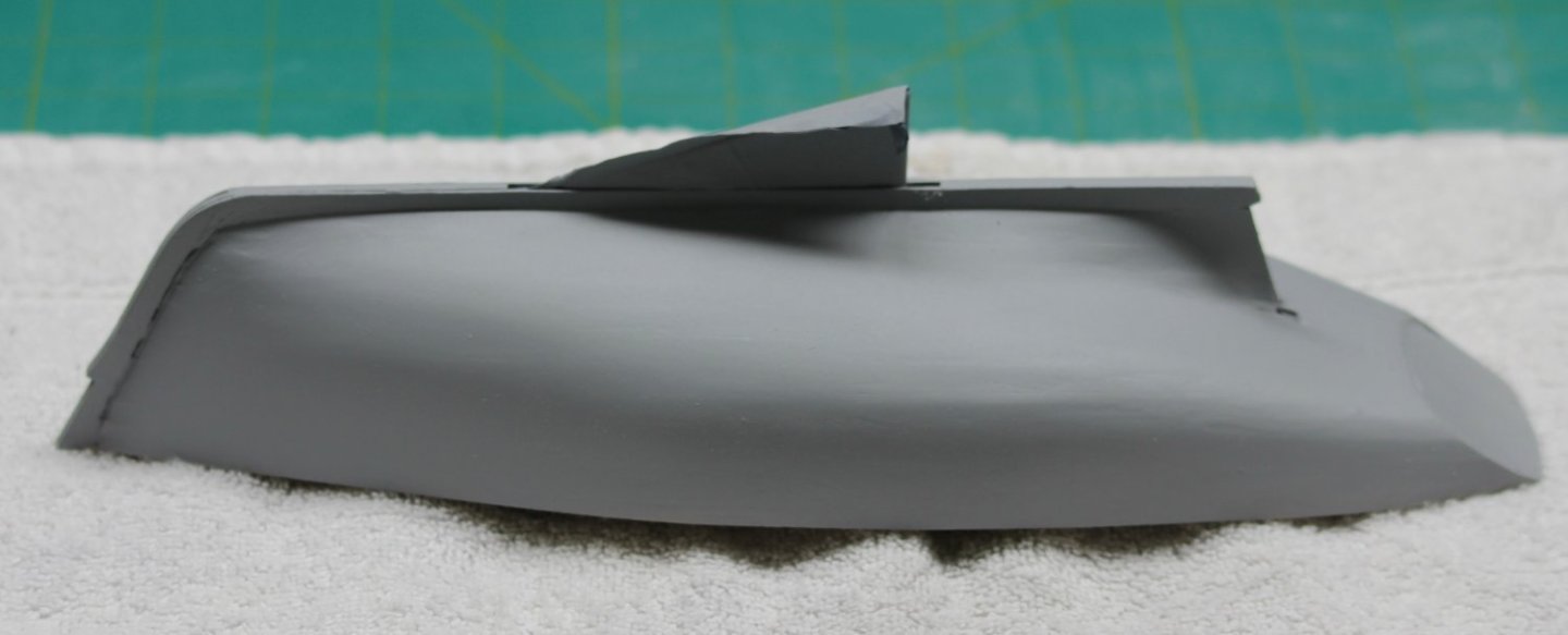
- 88 replies
-
- 4
-

-
- Muscongus Bay Lobster Smack
- Finished
- (and 1 more)
-
Sanding the problem spots with 400 grit paper. Don't ask me how I know but it really is possible to sand all the way through the planking even with 400 grit paper

- 88 replies
-
- 4
-
-
- Muscongus Bay Lobster Smack
- Finished
- (and 1 more)
-
Round 3 of the filler/sand repeat as necessary. This round is 400 grit paper. The next and hopefully last round is 600 grit or maybe 800 depending on how much filler is requiured after this round. The beauty of the filler/primer is it dries in less than an hour so you can get half a dozen runs in a Saturday and still have time for a few odd jobs in between. Hopefully one more pass will do the job here.
- 88 replies
-
- 5
-
-
- Muscongus Bay Lobster Smack
- Finished
- (and 1 more)
-
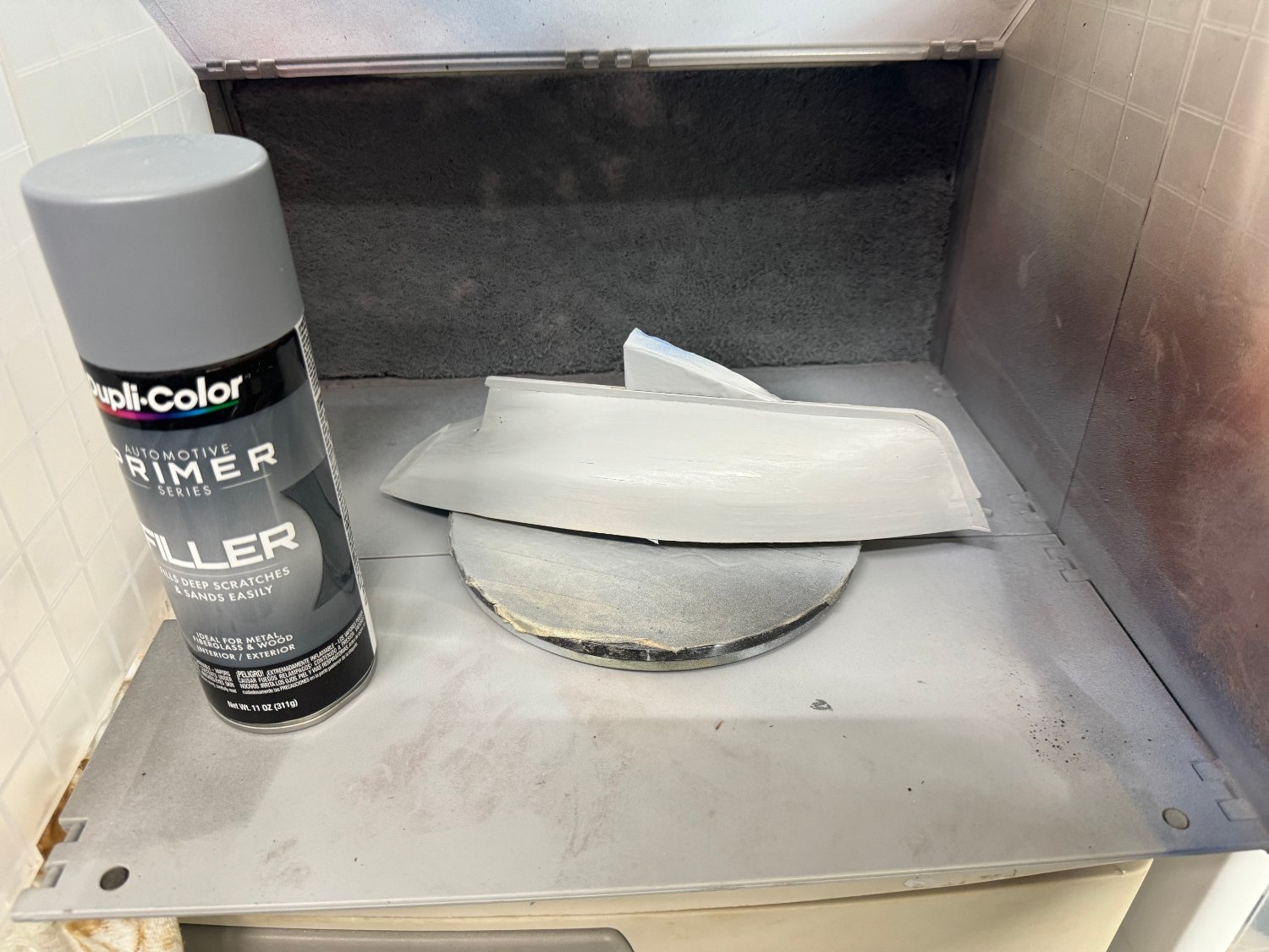
Hull in the paint booth with the paint.

- 88 replies
-
- 3
-
-
- Muscongus Bay Lobster Smack
- Finished
- (and 1 more)
-
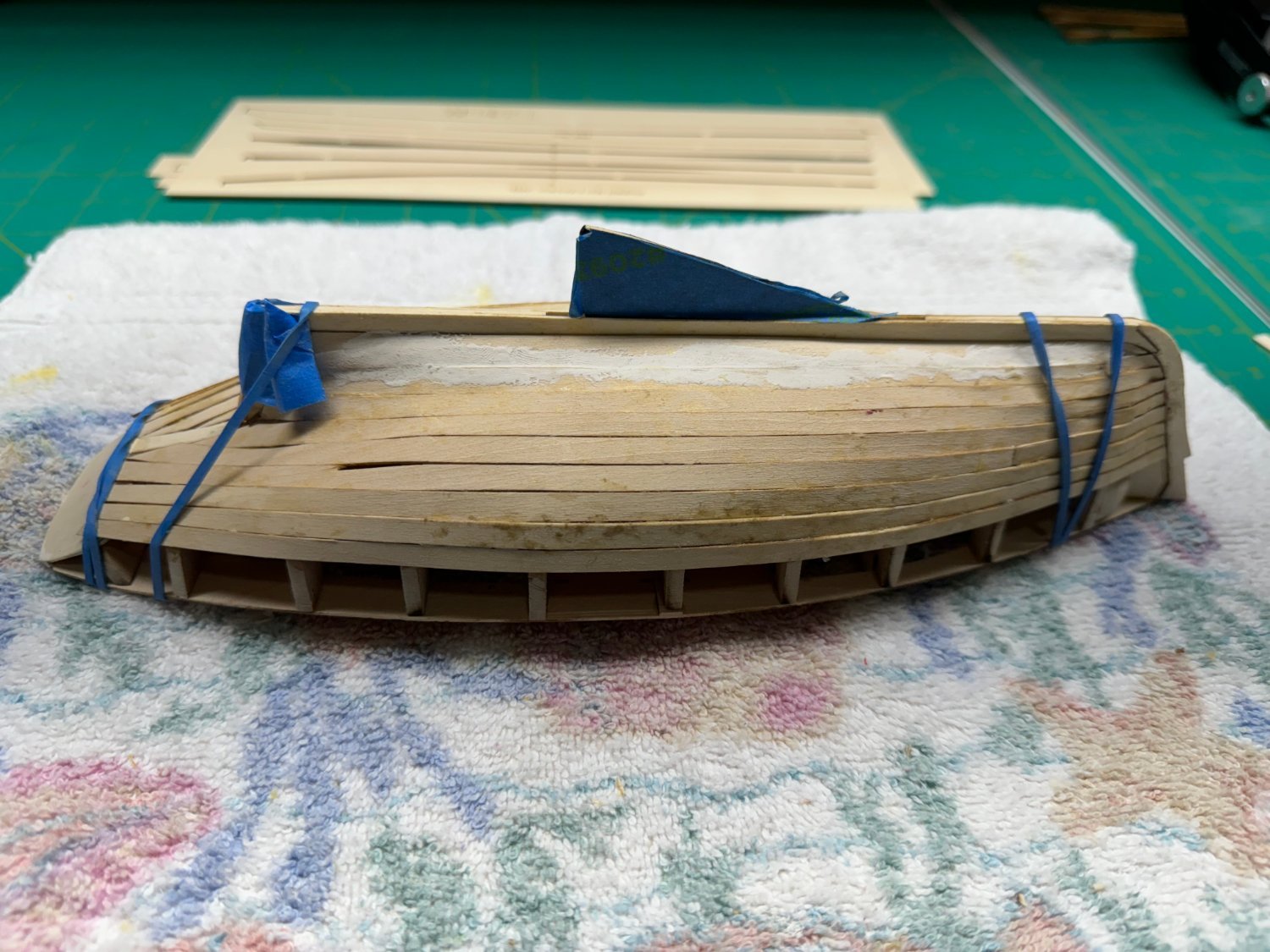
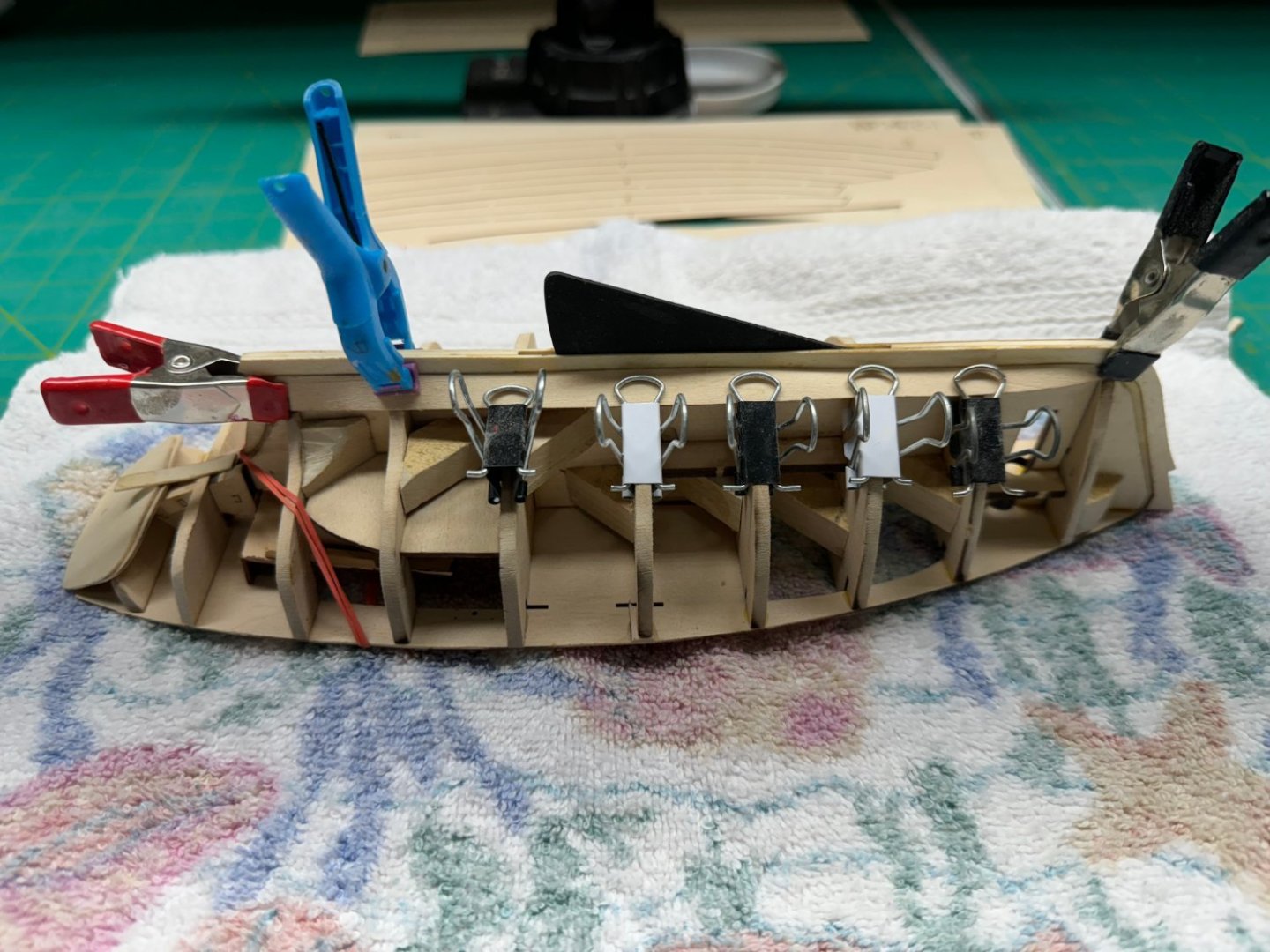
When I realized that I had skipped the "fair the hull" step and was half a dozen rows into planking on the pinnance I quit that effort and ordered a new kit from Vanguard - in fact I ordered a kit for all three boats such is my confidence it getting them all built successfully. I built the Model Shipways 18th Century Long boat to go on my Winchelsea model and it took two kits before I got a usable version. So... Here is the launch with five rows of planking on the sheer and the garboard strake drying in position. I started tapering the planks at both ends after the first three and that may have been a plank late but filler can cover many planking sins. I also started putting a drop of medium CA on all the keel/bulkhead joints as I had the keel come off the bulkheads once on the pinnance. It was quite an effort getting everything back together so I want to prevent a repeat. Even if the CA does show on the inside that area should be covered by the floorboards. Also since this kit has a great deal of PE Brass does anyone have a recommendation for how to prep the brass before painting and the type/brand of paint to use?
- 422 replies
-
- 5
-
-
- Vanguard Models
- Sphinx
- (and 1 more)
-
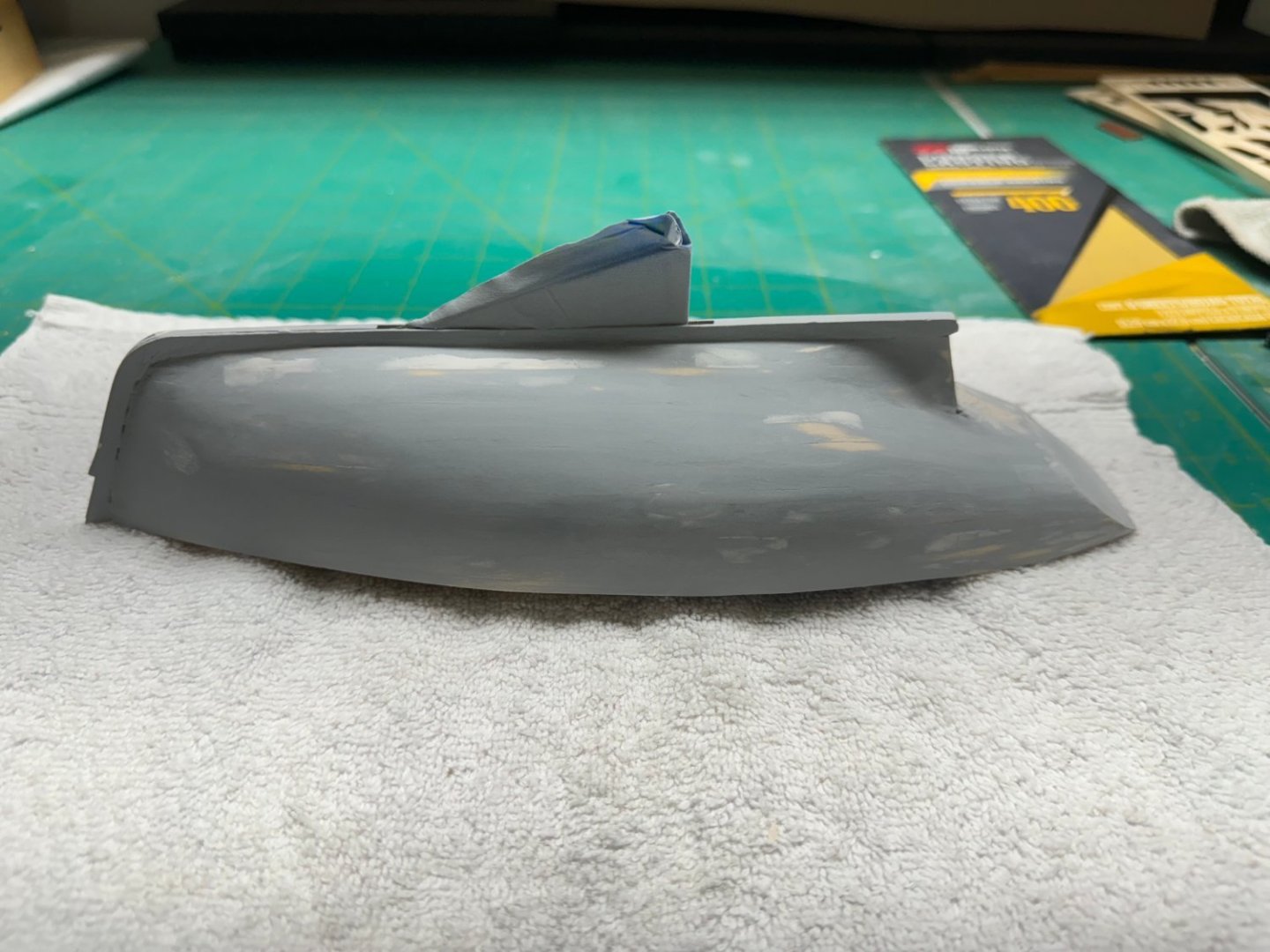
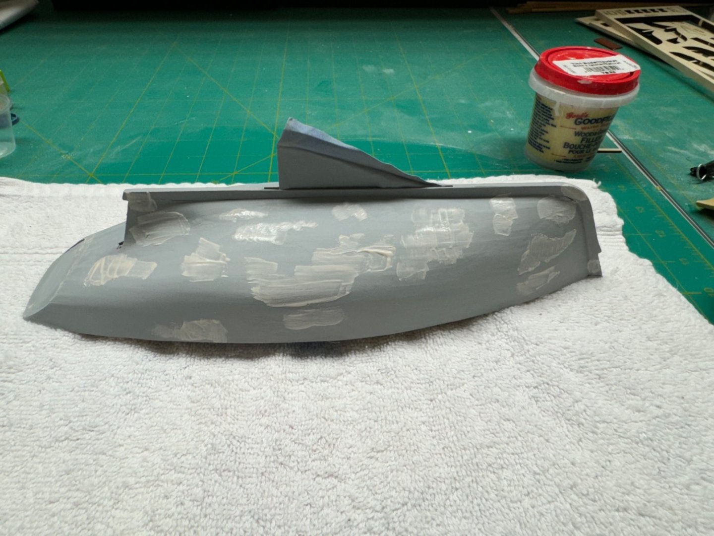
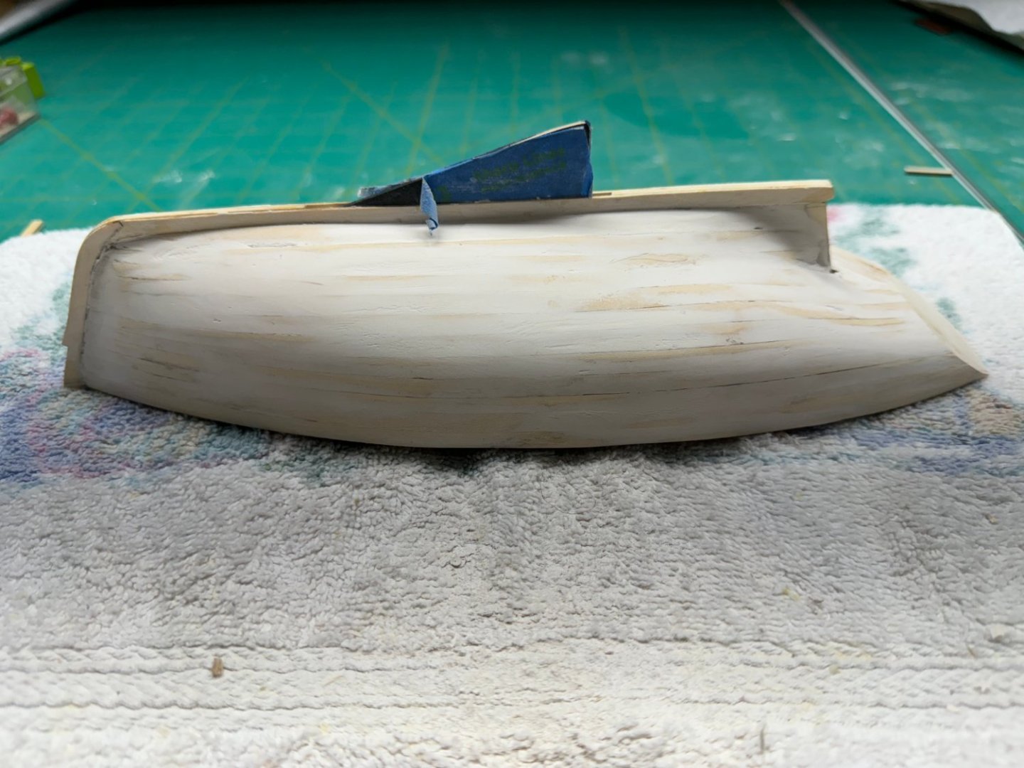
Sanddown of first pass with filler complete. Not bad (if I do say so myself). I marked the areas where further attention is required with a pencil and will apply more filler in those areas than do a sandown with 320 grit. After that comes the primer with filler and more sanding. And yes Bryan I also find the sanding quite relaxing. That is why I use the finer grit sandpaper - anything harsher and I would sand through the planking - it is after all less than .030" thick. One thing I noticed is that adding water to the filler seems to retard the drying time. I let the first pass sit overnight and plan on the same for pass 2.
- 88 replies
-
- 4
-
-
- Muscongus Bay Lobster Smack
- Finished
- (and 1 more)
-
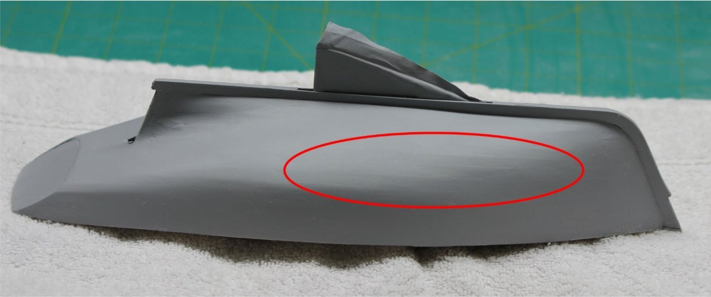
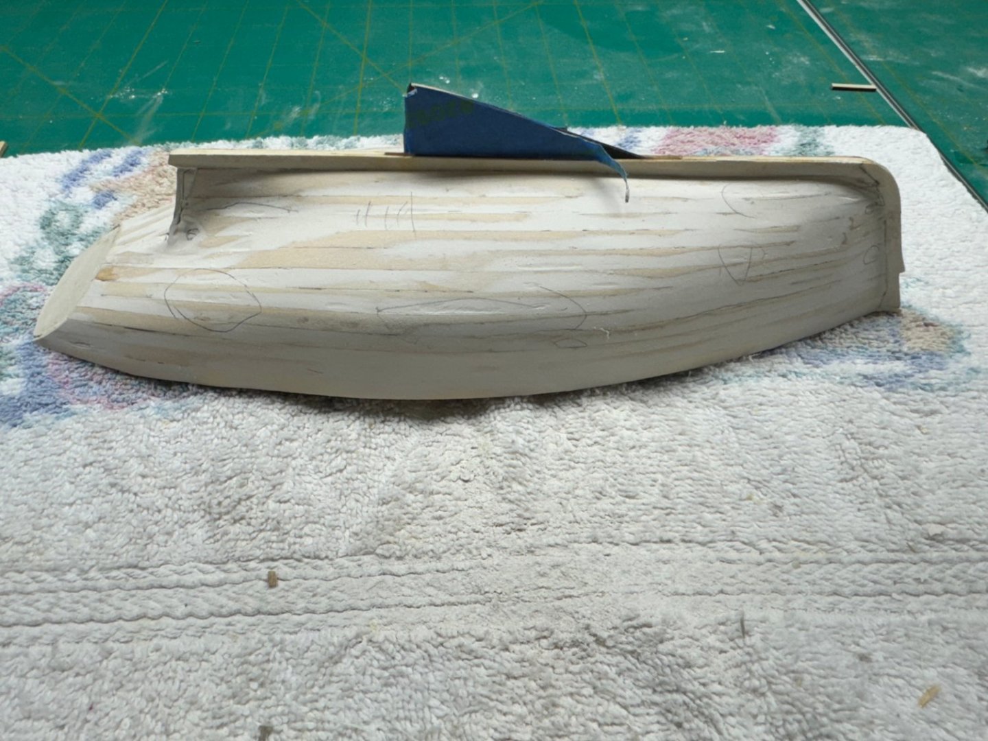
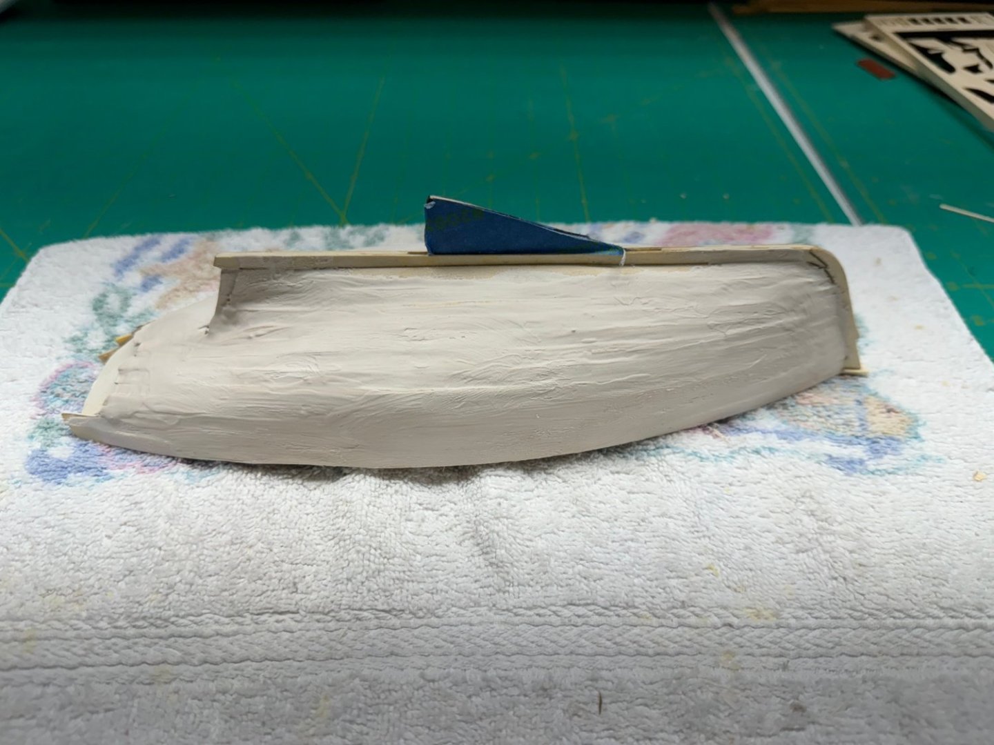
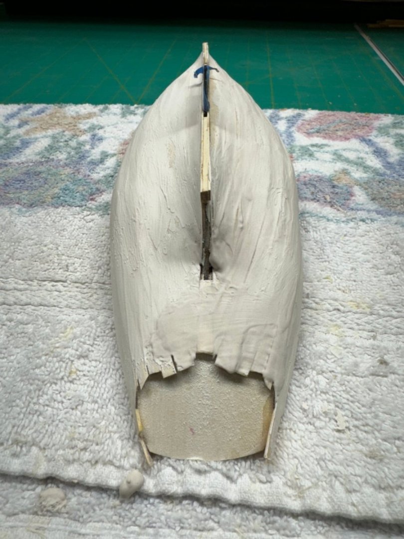
I completed the planking and have applied (liberally) thinned "Goodfilla" wood grain filler thinned with a little water (like 10 drops of water in .5 cu in of filler - enough so you can spread it thinly with a finger or piece of planking). I essentially covered the entire hull with filler. The plan is to remove the filler with 220 grit sandpaper and then rinse and repeat until I get it smooth (more or less). I bought a can of spray primer with filler at an auto parts store which I used successfully (more or less) on the hull of the 1/35th scale Endeavour Americans Cup challenger. This hull is about 1/8 the area of that one where I think I ran through 5 cans. I know where the store is if I need more 😃 I added some scrap wood to get the stem up to the level of the deck. It will be trimmed back as part of the filler "sanddown". So here is what the hull looks like now:
- 88 replies
-
- 5
-
-
- Muscongus Bay Lobster Smack
- Finished
- (and 1 more)
-
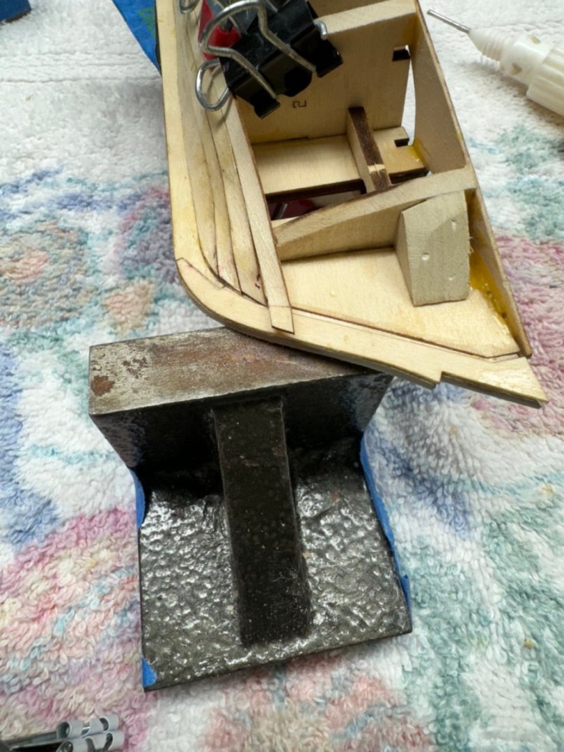
Eric, I considered that approach but decided to use the tools at hand. There will be of putty shortly.
- 88 replies
-
- 2
-
-
- Muscongus Bay Lobster Smack
- Finished
- (and 1 more)
-
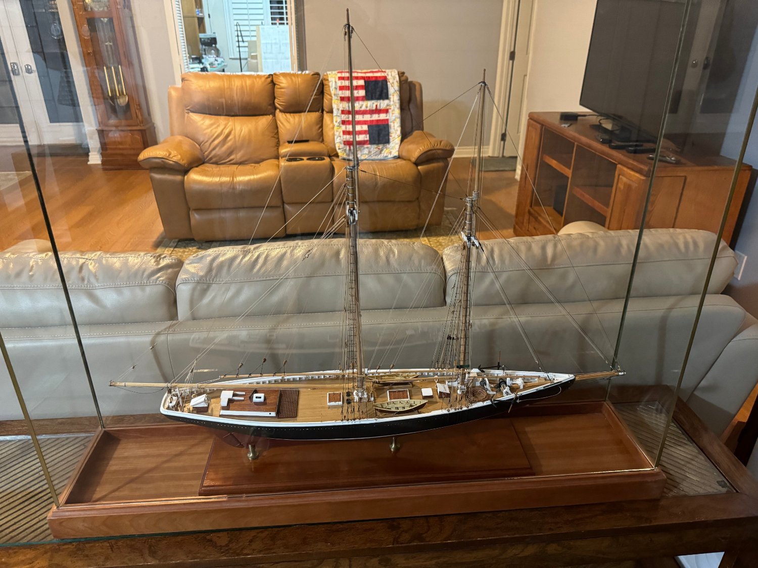
Thanks Greg - I built the Model Shipways Bluenose a few (maybe more than a few) years ago. It was a "fun" kit in that many of the parts you have to fabricate from stick wood - like hatch coamings as I remember it now. Here it is in the "place of honor" in the living room. That is the "shipyard" through the door with a drawing on the easel. I am also working on the Vanguard HMS Sphinx (working on the ship's boats at the moment which the lobster smack is occupying the primary work space) and many (if not most) of the parts are either prefabricated or a series of parts that are essentially assembled into the capstan for instance. The Sphinx has like 15-20 sheets of laser cut parts and several sheets of photo-etched brass. And it was not cheap.

- 88 replies
-
- 5
-

-
-
- Muscongus Bay Lobster Smack
- Finished
- (and 1 more)
-
Thanks Bryan. I got strake 9 on the starboard side. Then realized that my measurement of the space to be filled by the sheer strake was a bit off. There were two small areas one at the bow and one just aft of amidships where the sheer strake was going to be just below the deck. Not good. I considered several alternative solutions - putty, some very small (almost slivers) pieces glued to the sheer strake, or create a new sheer strake a bit wider where required. Putty probably would not hold in place during the rest of the puttying and sandin g that is about to begin. The small pieces would probably not stand up well to that either so I decided to make a new sheer strake. Actually I covered the remaining area with two strakes. They were originally 1/16" X 1/4 inch basswood (from some long forgotten project) which I reduced to .0290" (which is the thickness of the material supplied in the kit) with the thickness sander. I adjusted the width to fit the profile and to more or less evenly distribute the remaining area. Here is the starboard side with the first strip installed. And here with the final strip although it has not been trimmed to be even with the deck yet. I will follow the instructions and trim to the deck after the filler stage is complete. On to the port side where I expect the same problem and solution.
- 88 replies
-
- 5
-
-
- Muscongus Bay Lobster Smack
- Finished
- (and 1 more)
-
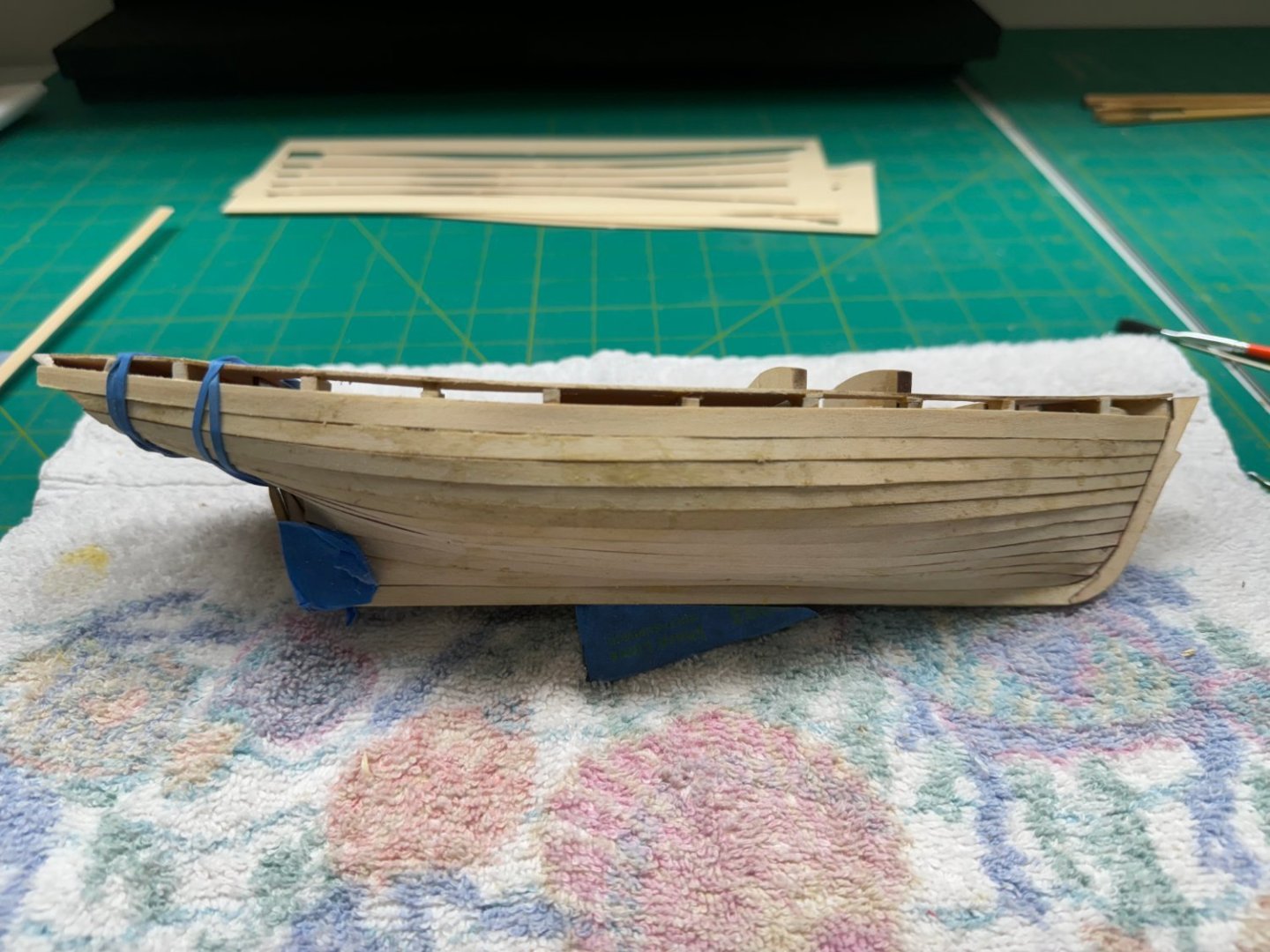
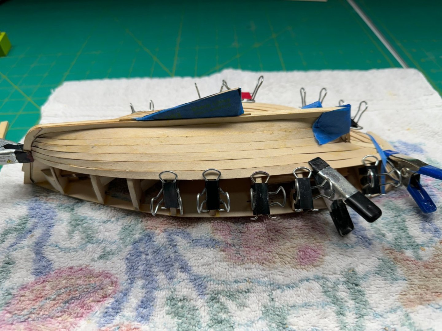
Strakes 6,7 and 8 have been added. I dispensed with the soaking, bending and drying starting with strake 6 as the wood was pliable enough without these efforts. I checked and while it will be close in a few places the sheer will clear the top of the deck everywhere if my measurement are accurate.

- 88 replies
-
- 4
-
-
- Muscongus Bay Lobster Smack
- Finished
- (and 1 more)
-
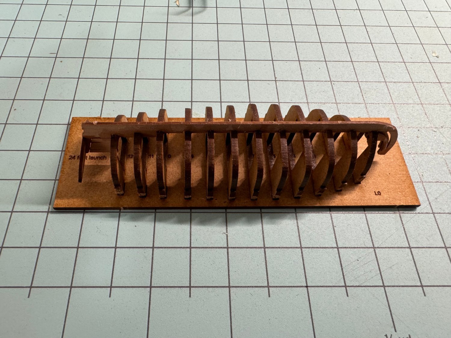
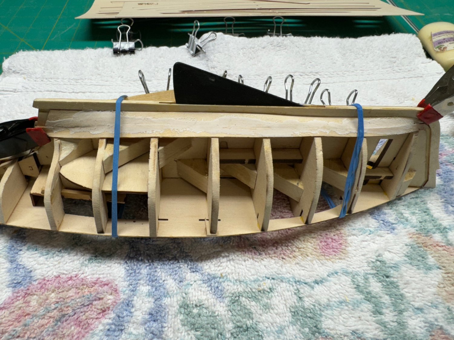
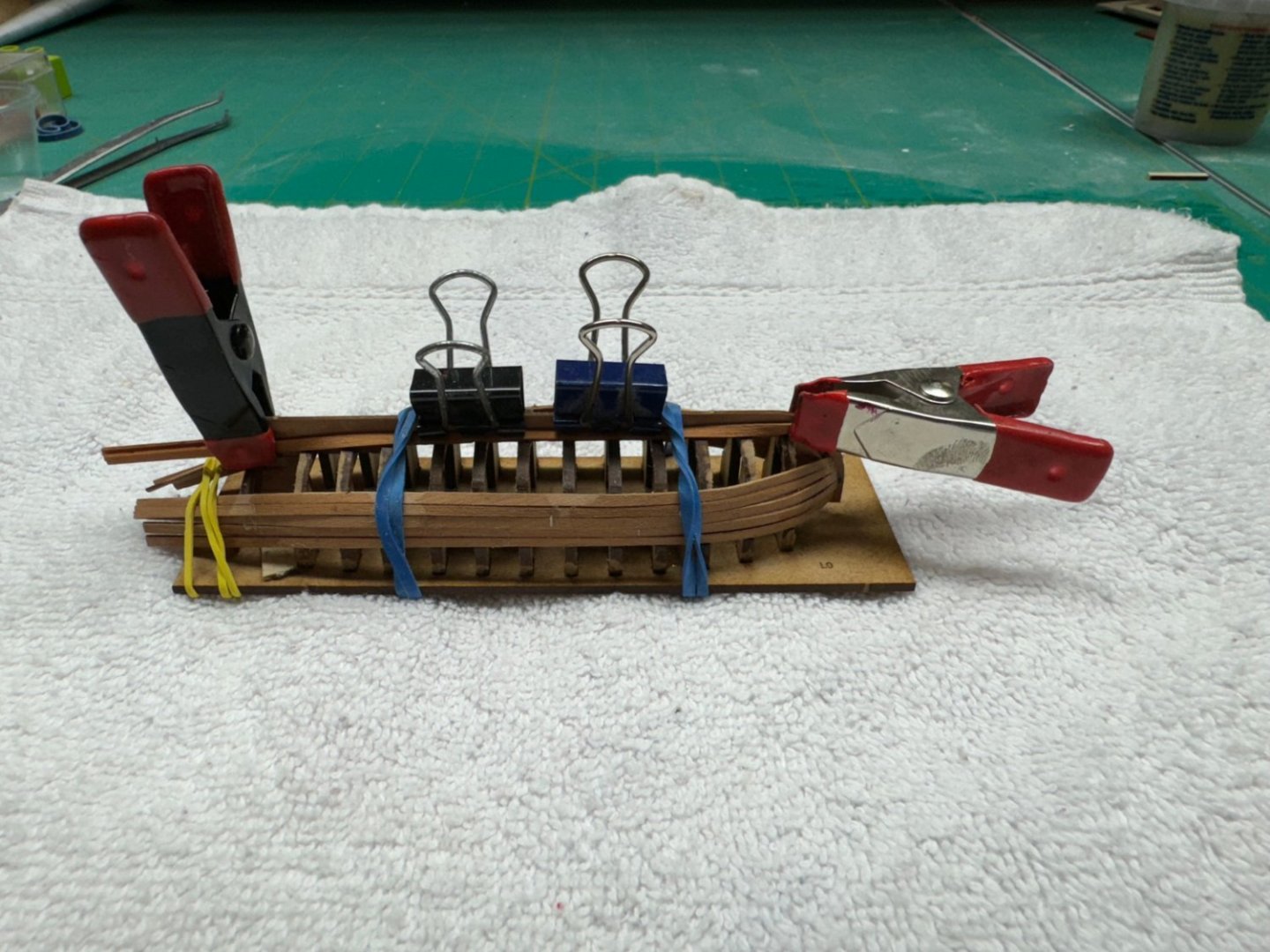
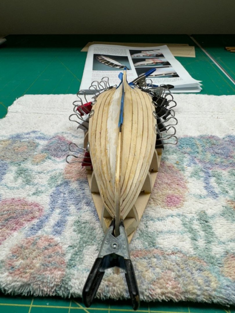
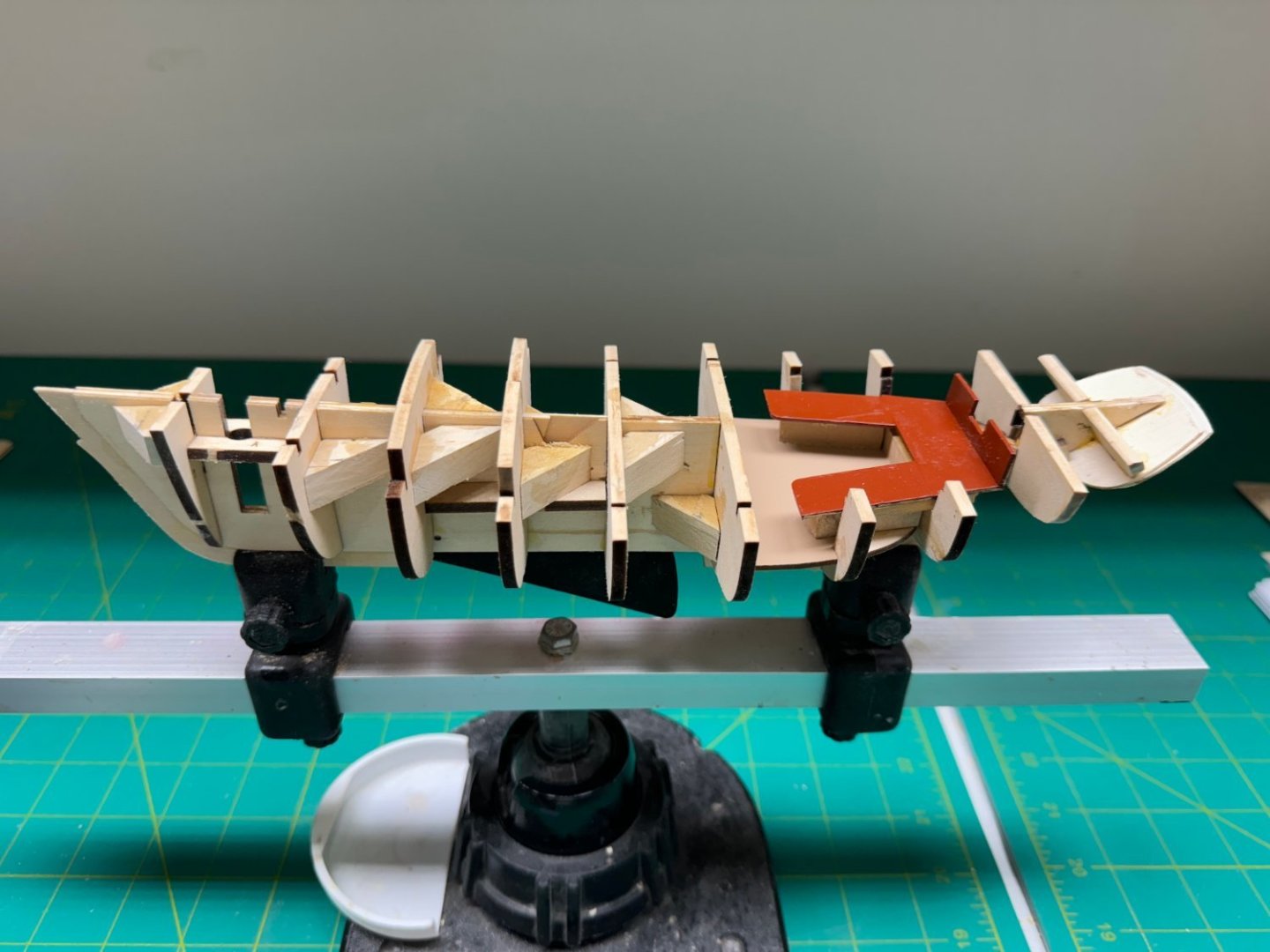
Pinnance with 3 rows at the sheer and two at the keel. I will admit to using thin CA in a few places, principally at the bow to get the planks to "stick" before running them the rest of the way aft. And here is the skeleton for the 24' Launch ready to start the planking process. I have 6 planks in the "bending jig" to cover the first three rows.

- 422 replies
-
- 9
-
-
- Vanguard Models
- Sphinx
- (and 1 more)
-
Greg - I meant a three masted ship with the masts, yards and rigging. If we count Winchelsea than Confederacy would count as well. 😄
- 422 replies
-
- 2
-
-
- Vanguard Models
- Sphinx
- (and 1 more)
-
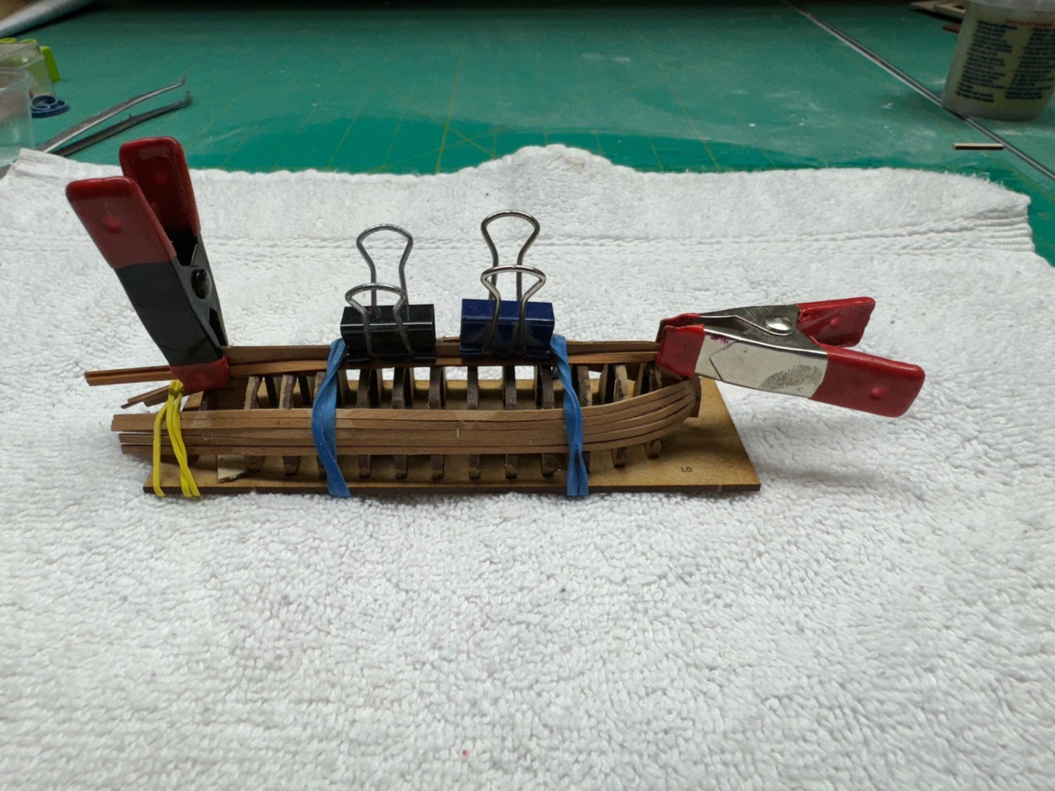
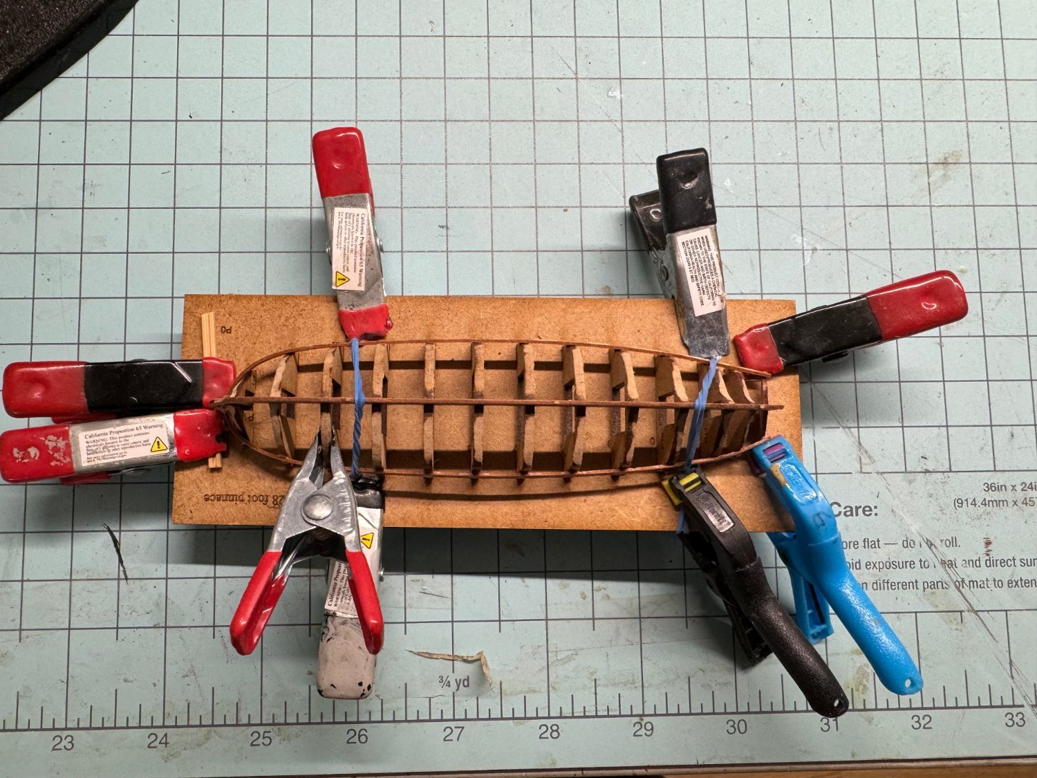
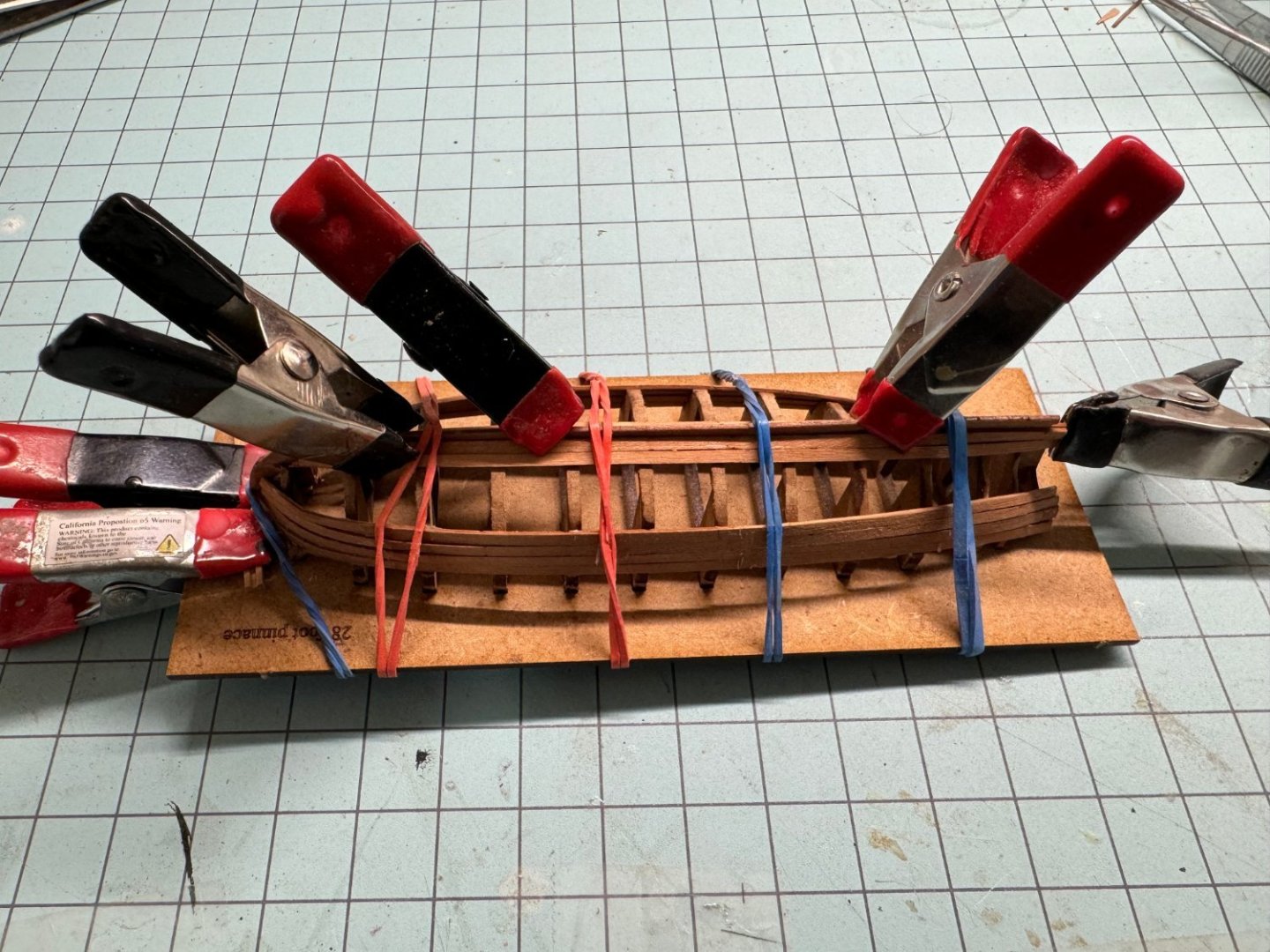
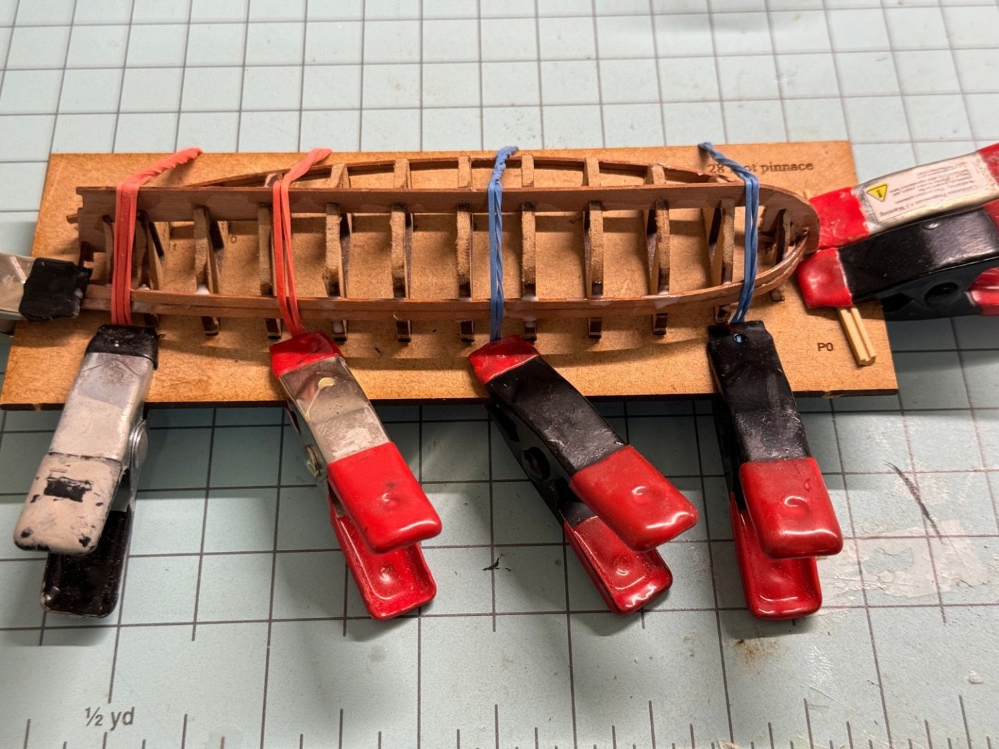
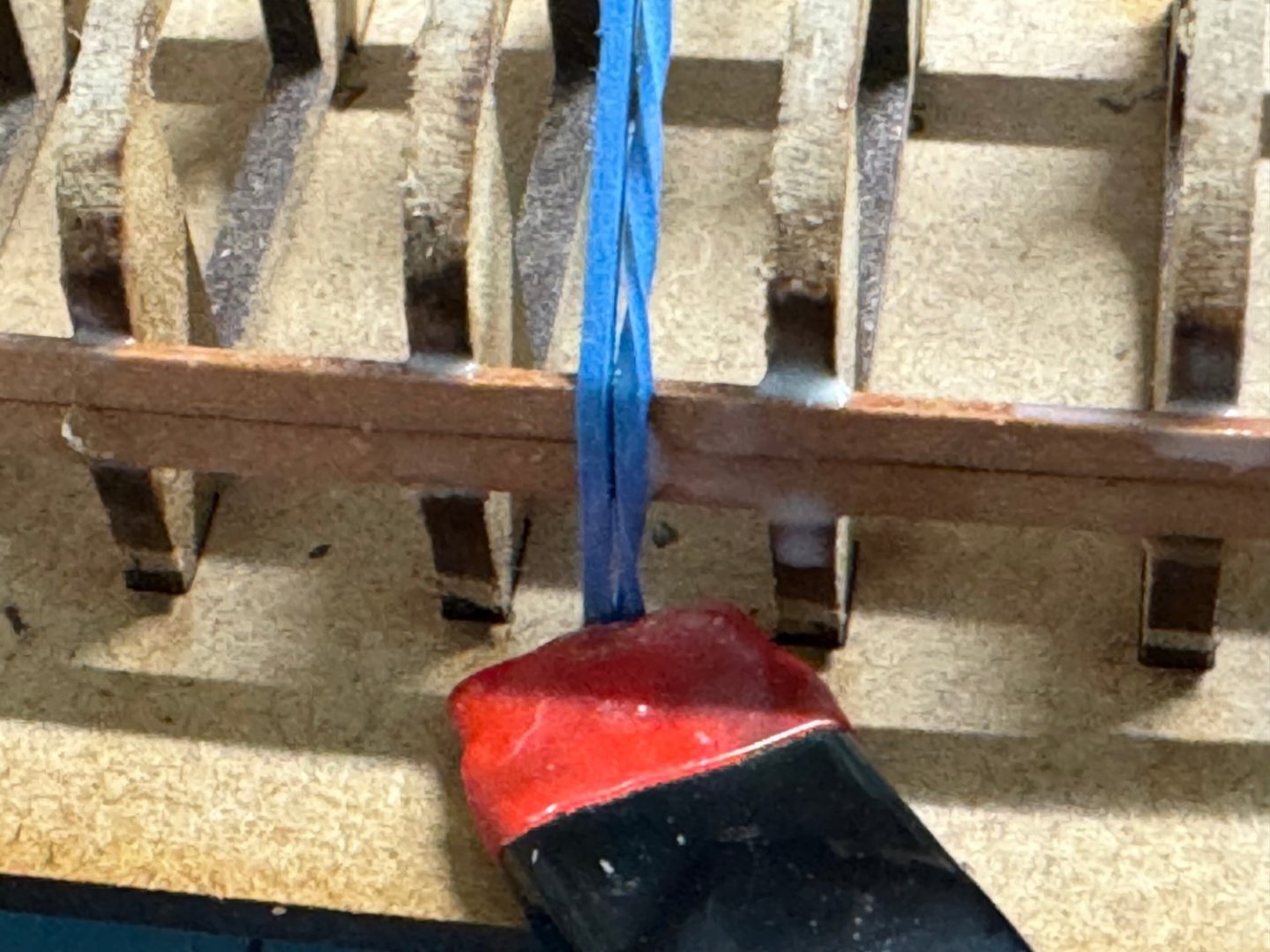
I am starting the Sphinx as my first model of a three masted ship with masts, yards and rigging. I completed the brig Niagara several years ago but since then have only built fore and aft rigged vessels or Admiralty models and want to get a three master done before my eyesight and hand eye coordination make that impossible. Because I am working on another small model in the main work area I will start by building the three ship's boats. This is the 28 ft pinnance with the first row of planking. It is quite a challenge (for me) to get these very tiny strips to lay where they are supposed to in spite of have between pre-bent and thoroughly dried. The two clamps at the bow are to hold the stem in place - pressure from the rubber bands makes it want to shift to one side or the other. And now with two rows. I use the clamps to push the rubber bands to slightly inside the planking so they will hold the planks both against the ribs and the plank below. I use thinned PVA applied with a brush to the rib contact area and to the seam between the planks.

- 422 replies
-
- 10
-
-
- Vanguard Models
- Sphinx
- (and 1 more)
-
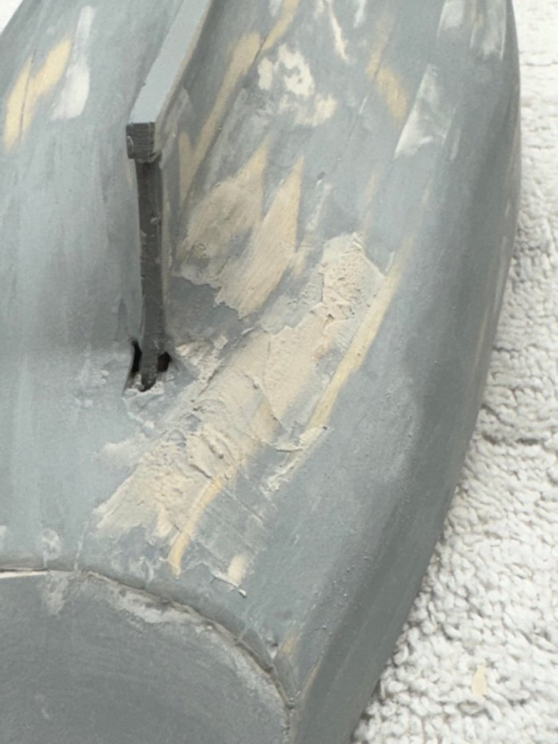
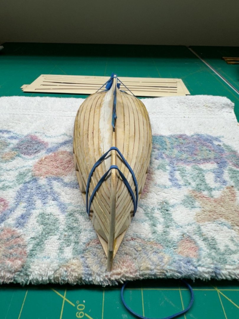
Strake 5 in place. Now that the strakes with the angled aft end are done it is back to starting at the bow. I cut a filler piece to go in the hole for the rudder to make sure I do not get any filler in there as this area is one where probably the most filler will be required. And here is the hull from each side. I put tape over the centerboard to try and keep the damage to a minimum. Note the void on the port side aft where the strake did not come off the carrier cleanly and the bulge at the bow (subsequently "fixed"). The hull has developed a dip between bulkheads 1 and 2 which will need filler to resolve. I guess I could have done a better fairing job at the bow.

- 88 replies
-
- 3
-
-
- Muscongus Bay Lobster Smack
- Finished
- (and 1 more)
-
Strake 3 has a notch at the aft end which I suppose should fit around the stern post. Putting strake 3 where it seems designed to go will leave a gap between it and strake 2. I like deal with the gap later and put strake 3 where it appears it should go. However, locating strake 3 here causes a problem at the bow The stake is too long but cutting it to fit with a Xacto #17 (square end) solves that roblem. And now the strake 3s are in place to dry until halftime in the 49/Lions game when I will put the soaked strake 4s on the model to dry overnight.


- 88 replies
-
- 4
-
-
- Muscongus Bay Lobster Smack
- Finished
- (and 1 more)
-
Strake 2 in place. I had to modify a couple of the bulkheads to get a smoother run near the stern. Also, the planks continue to run longer than required which is a good thing. One trick I saw somewhere is to use PVA/Carpenter's glue between the strakes and a drop of medium CA on the bulkheads. You can use the CA to hold the strake while the PVA sets up.
- 88 replies
-
- 2
-
-
- Muscongus Bay Lobster Smack
- Finished
- (and 1 more)
-
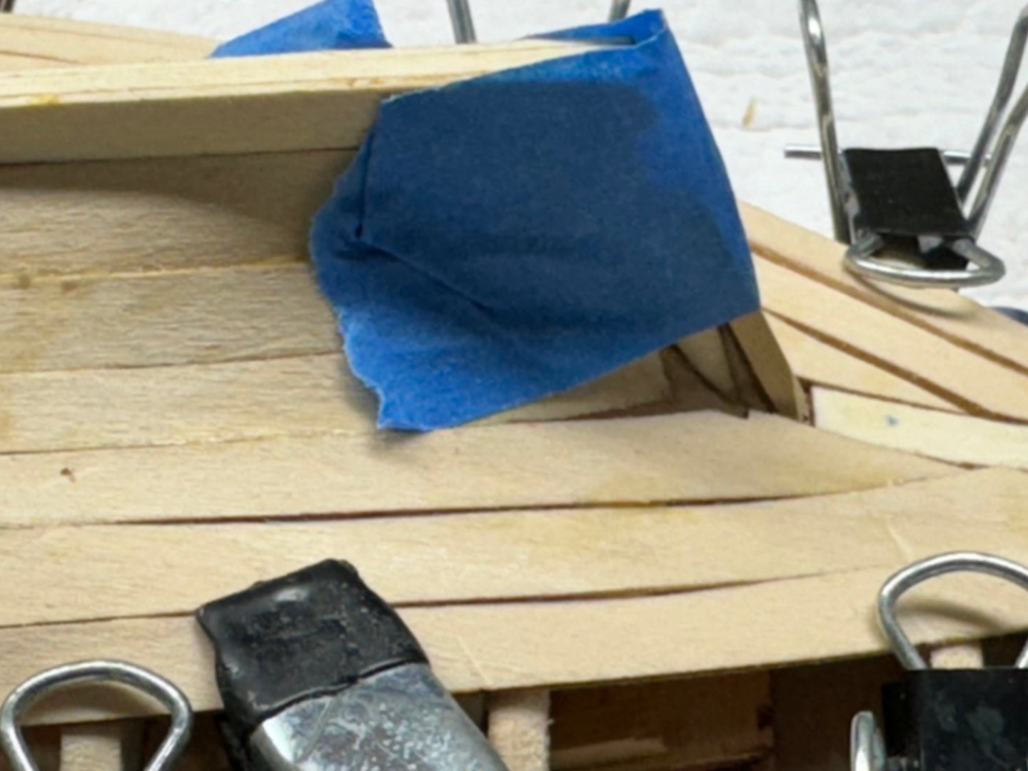
Strake 2 in position for drying. The two "extra" clips on the starboard side are to align the edges of strake 2 with strake 1. That was not a problem on the port side.

- 88 replies
-
- 4
-
-
- Muscongus Bay Lobster Smack
- Finished
- (and 1 more)
-
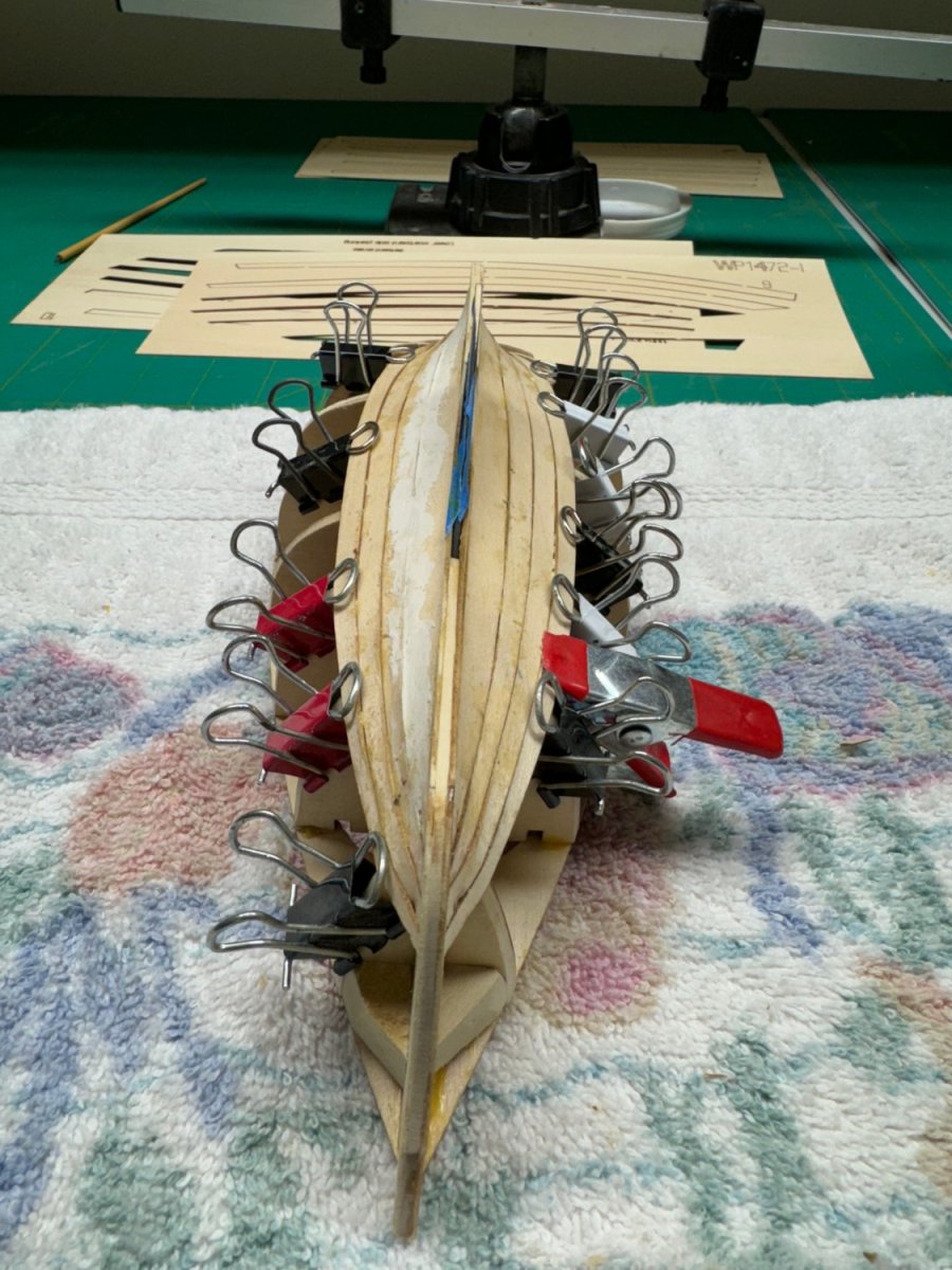
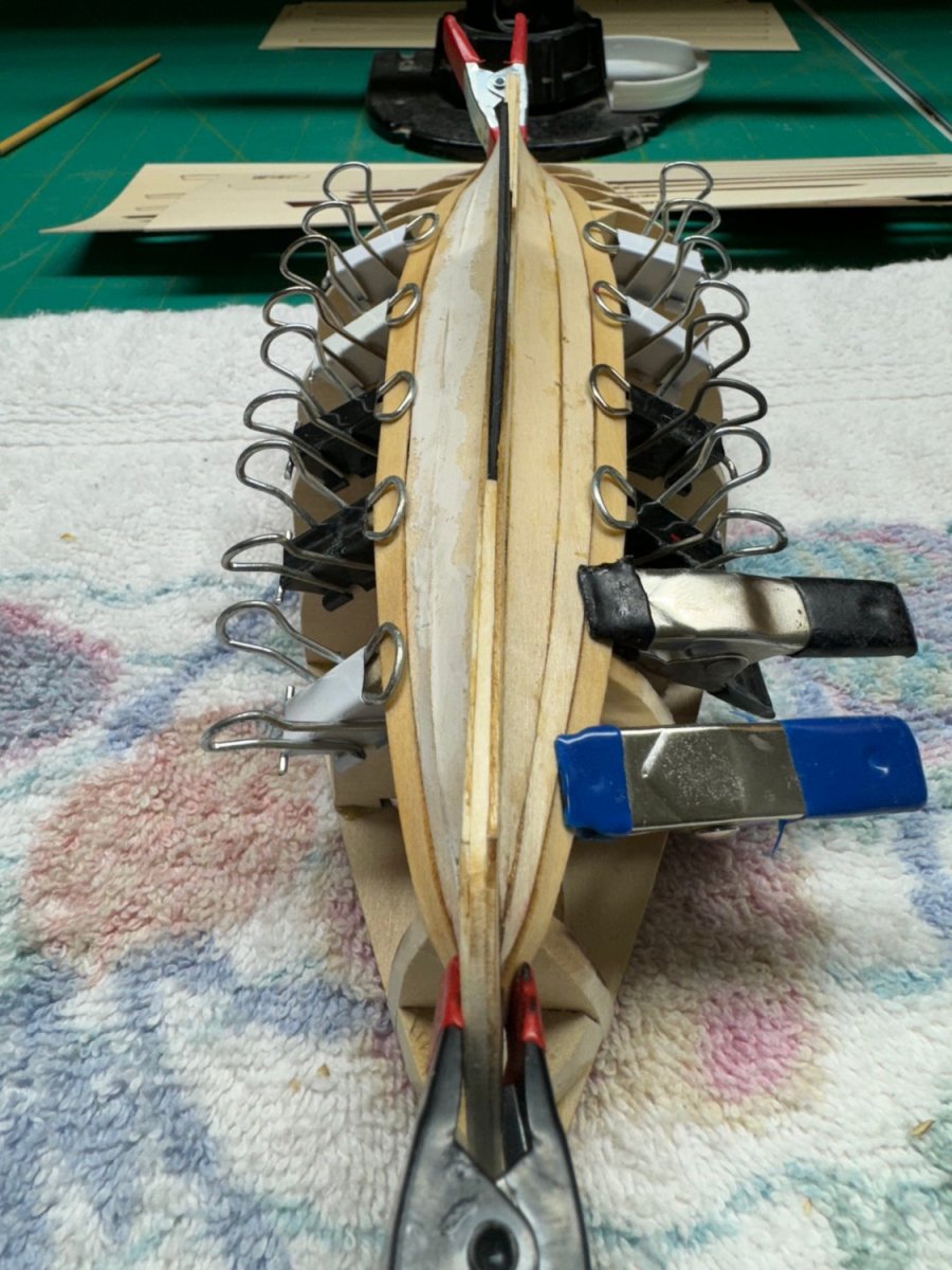
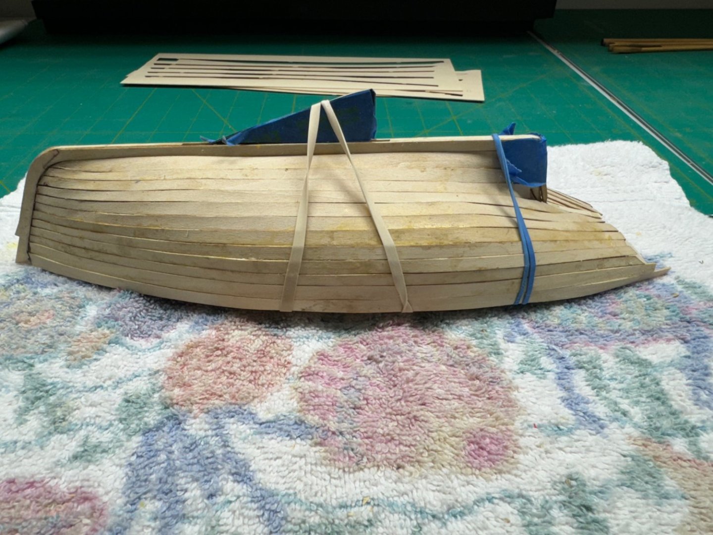
Strake 1 installed on both sides. Waiting for starboard side to dry then on to strake 2. On the garboard strake the instructions say to start from the stern which is correct since we know where that has to end (stern post). On strake 1 I started at the bow (since the start point there was defined by where the garboard strake ended) and found that the strake supplied is .25" or so too long (sorry that is hidden by the clamp in the photo). So it appears that all the rest of the strakes should be fitted from bow to stern,+ While waiting for the other side to set up I thinned out some Goodfilla wood filler enough so I could use a brush to apply it and brushed on filler at the joint between the graboard strake and strake 1. I plan on doing that for each strake (but will wait until the entire hull is planked) as a starting point for finishing the hull. Hopefully i will not have to resort to covering the entire hull in filler although I have seen that movie and while messy it will yield a reasonable looking hull.

- 88 replies
-
- 4
-
-
- Muscongus Bay Lobster Smack
- Finished
- (and 1 more)
-
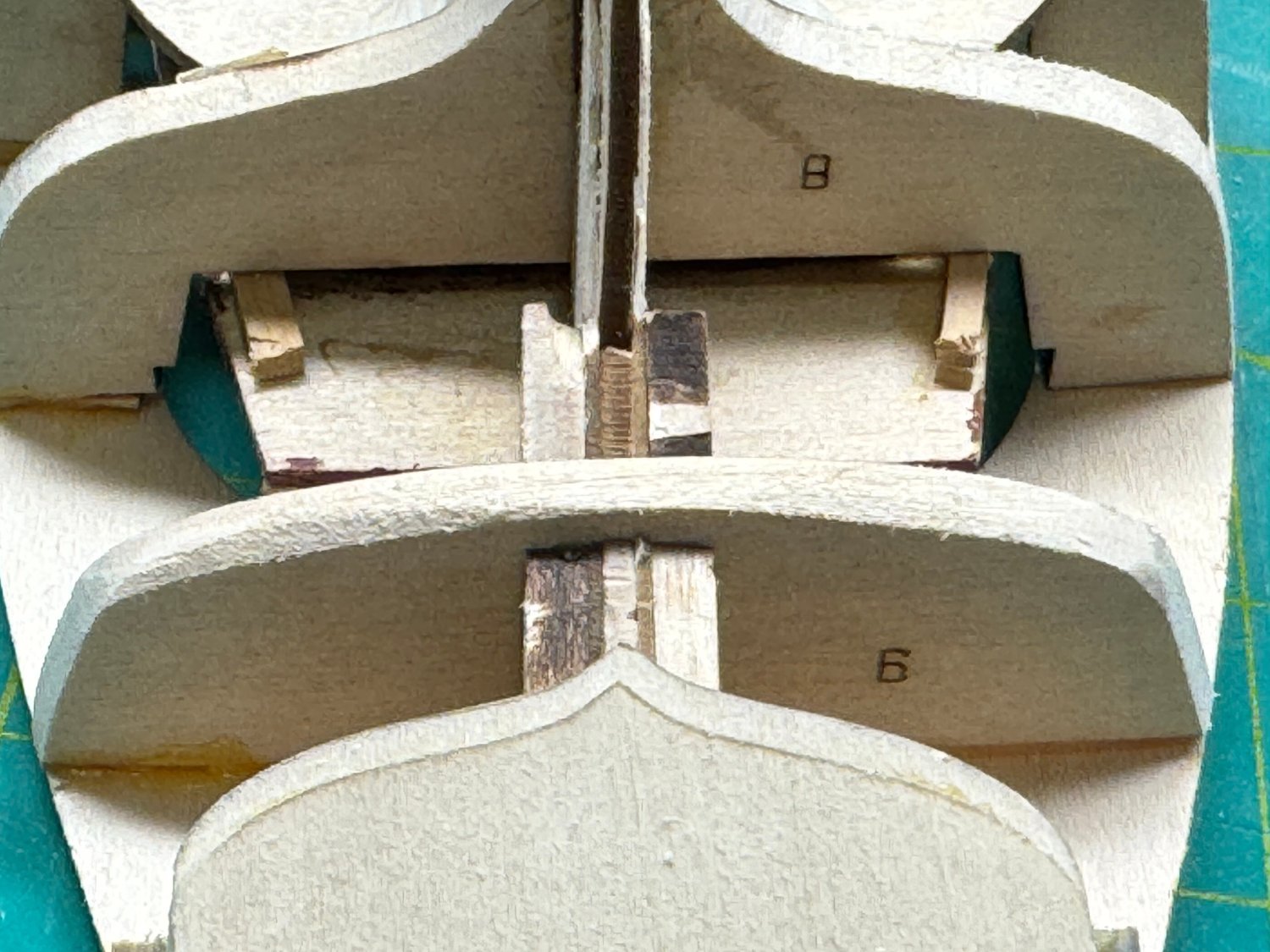
Eric, I have to agree since we experienced opposite effects so there must be something in our assembly techniques AND the limitations of building the structural components of the hull from a very soft wood. In addition there is a very weak point in the spine at bulkhead 9 that could cause issues with the transom. A small change in that area could cause the transom to be either too high or too low. In my next project the structural components are made from MDF which is considerably stronger that the basswood/limewood here.
- 88 replies
-
- 2
-
-
- Muscongus Bay Lobster Smack
- Finished
- (and 1 more)
-
Port side garboard stake in place waiting for glue to set. I soaked the strake in hot (190 degree - Insinkerator hot) water for a few minutes, got it in position then used a hair dryer to dry the plank. Only took a few minutes and the plank was ready for installation. Titebond glue (what I am using) is pretty firmly set in about 30 minutes. So I should be ready for the starboard side before I quit for the day.
- 88 replies
-
- 2
-
-
- Muscongus Bay Lobster Smack
- Finished
- (and 1 more)
-
I had exactly the opposite problem - I had bulkheads that stuck out beyond the deck edge. And like you it was not that the ones on the other side were too far in. I had three on one side and one on the other. Go figure. It took a good bit of sanding to reduce the bulkheads to be level with the deck edge. I have just started planking - garboard strake, so I may yet " pay the price" what whatever I did wrong.
- 62 replies
-
- 2
-
-
- Muscongus Bay Lobster Smack
- Model Shipways
- (and 1 more)
-
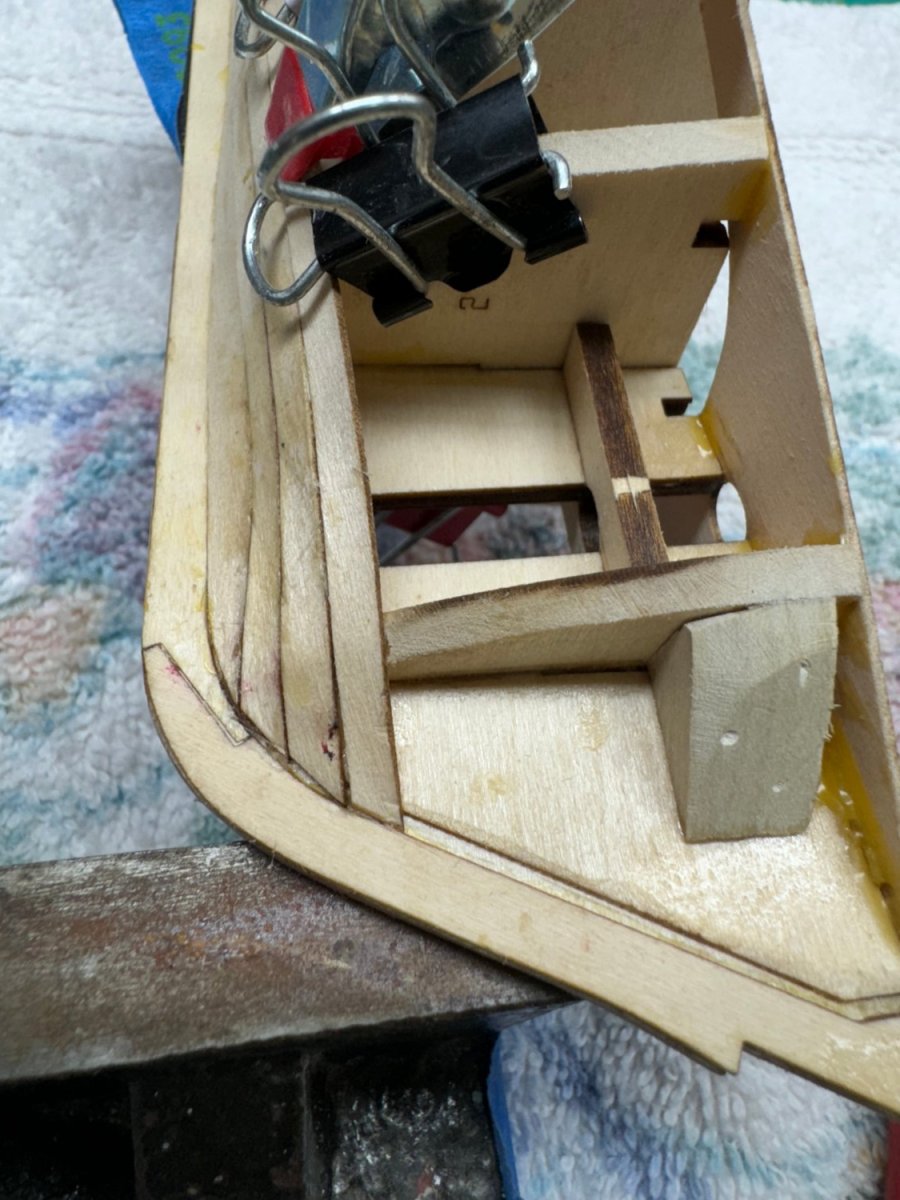
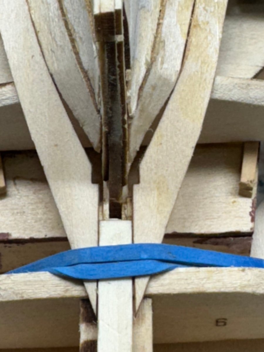
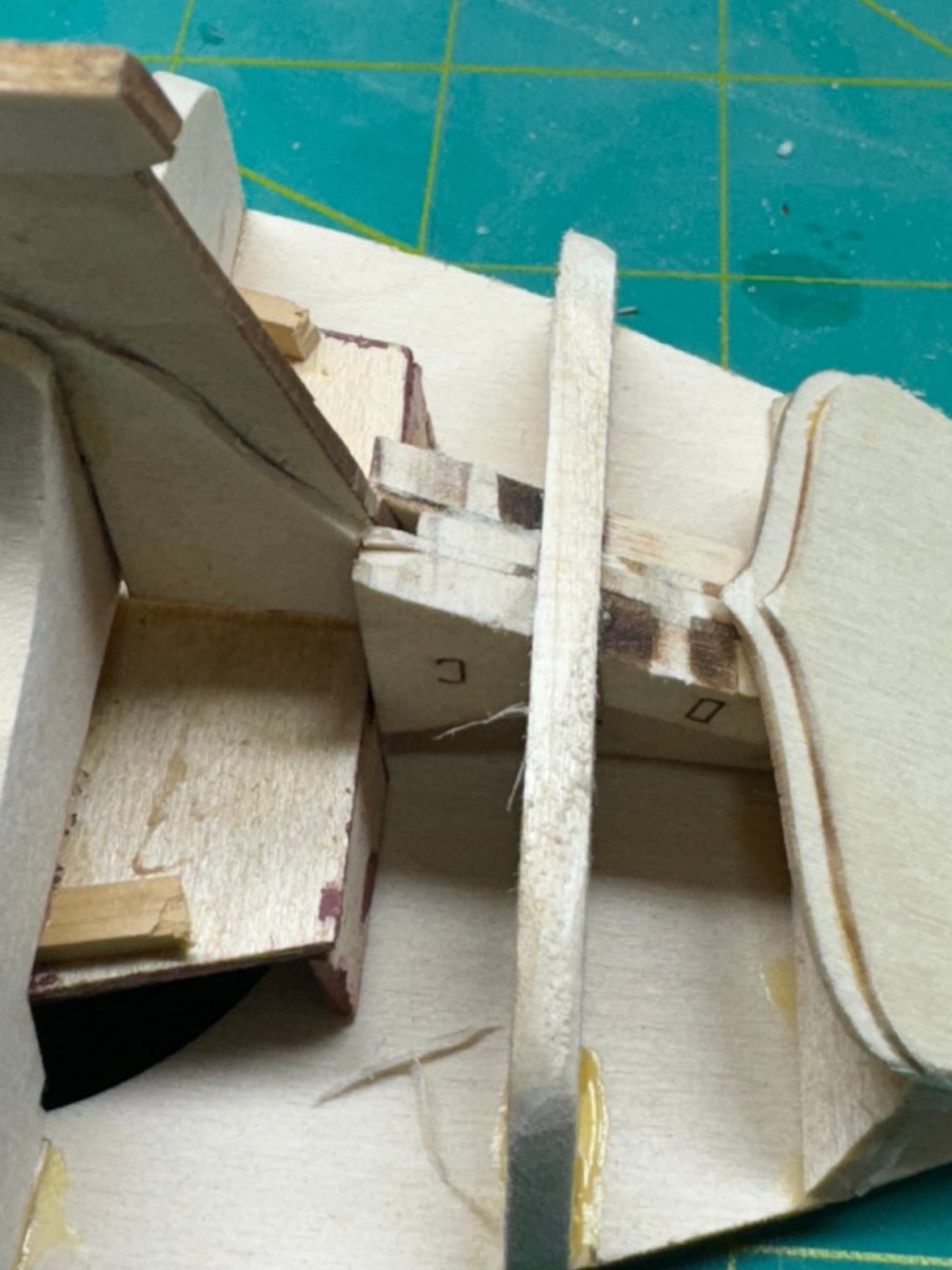
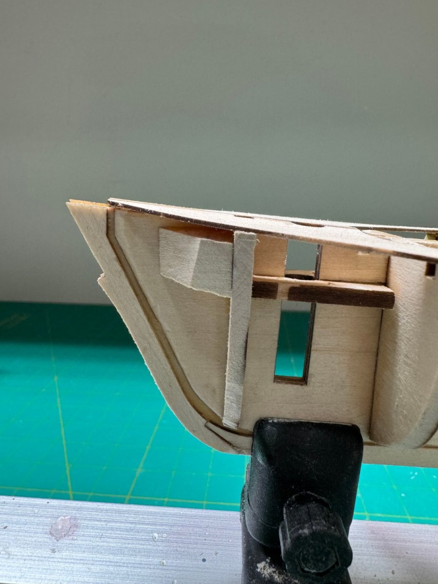
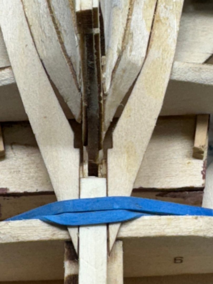
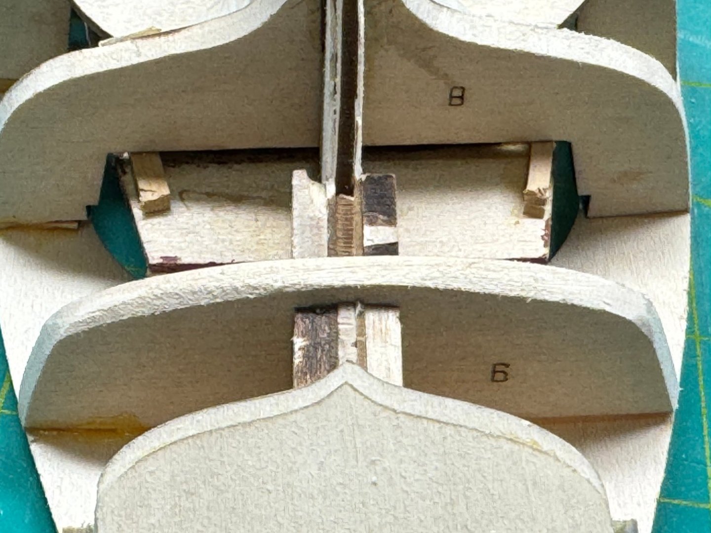
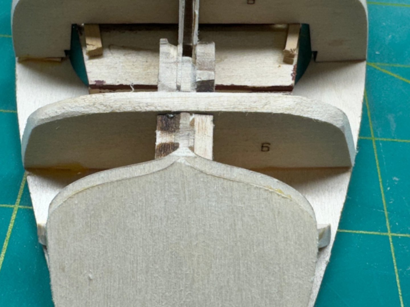
I got the hull faired - I broke my own rule and used mostly 110 grit sanding sticks for the fairing. Where the bulkheads extended past the decking it took a good bit of sanding, even with 110 grit to get the bulkhead reduced to the deck edge. While installing the keel and stern post I noticed the instructions admonition that the plank supports are flush with the spine. In my case the supports were flush (more or less) but bulkhead 9 extended beyond the spine by more than a little. See below: So out came the 110 grit sanding stick again and I reduced bulkhead 9 to be level with the plank support pieces. I had to refair the bulkhead 9 and 8 to get the flow correct. I am hoping that this will all "come out in the wash" when the planking is done but... Now that this area is as described min the instructions I added the central plank and left it extended over the transom. The problem is that with the center plank on top of the transom only the part on and forward of bulkhead 9 is attached to the frame. Not sure what, if any, impact this will have on the planking but it bears watching. Two other issues as we near the planking stage. One the stem is not flush with the deck. I am not sure how it could have been since the decking went on top of the center spine and the spine was flat in that area. If this becomes an issue I will cut and shape a piece to extend the stem up to deck level. Two, the deck does not extend all the way to the transom. Either my transom is sloped too much or I put the deck on too far forward. The deck location aft is determined by the center board section fitting against bulkhead 4. If this joint is tight then the stern falls where it falls. I will put some filler in here when the planking is done.


- 88 replies
-
- 2
-
-
- Muscongus Bay Lobster Smack
- Finished
- (and 1 more)
-
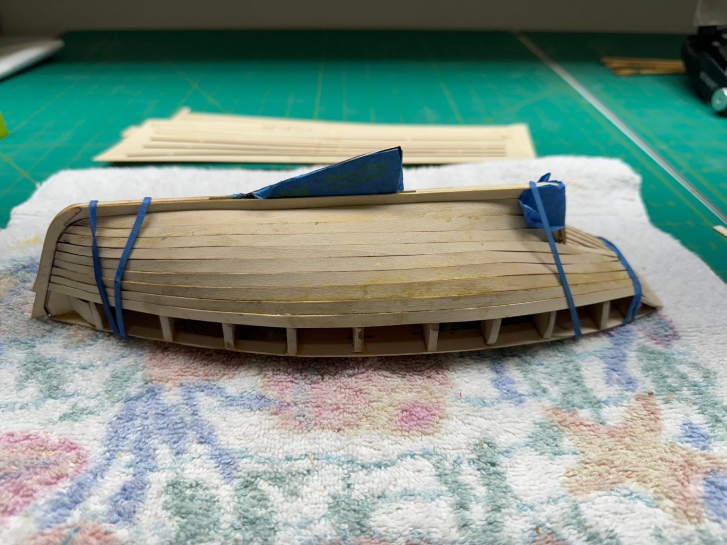
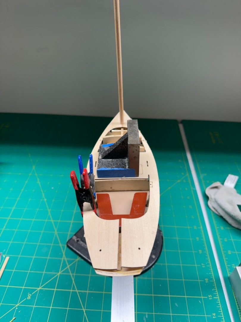
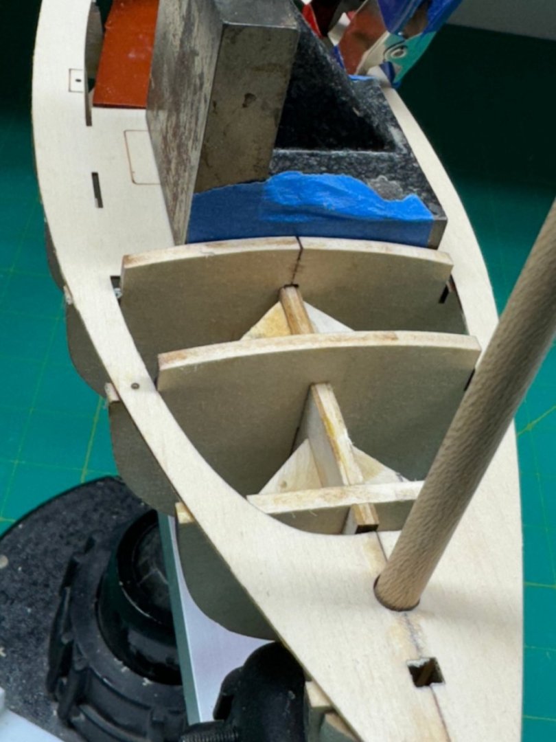
The deck - hmmm, should be easy I thought. I dry fit the starboard half but after several fitful attempts to get everything in place at the same time I put some dabs of glue in strategic spots and tried again. I found three spots that needed attention, all where the deck support was too low. Probably means the bulkhead was not level port/starboard and the port side in these locations is probably high. Fitting the port side deck however did not bear that out. It had one bulkhead which was low as well. And it was not the same as any of the three on the starboard side. Given that I thought maybe it would be better to try and do both sides together, but starting at the bow and working aft. One more point - if you are planning on a fixed centerboard in the down position wait until after the deck and planking is done to install it. Mine keeps getting in the way of rubber bands. Here is the deck done to midships, both sides. The weight is holding down the two center section astride the centerboard trunk. The two clamps are keeping the port side deck even with the bulkheads on that side. Left to its own devices it would be well outside of the bulkhead ends. Given the unevenness at the bow this is probably not surprising. Going to have to be more than a little firing before the planking can begin - at least at the bow.
- 88 replies
-
- 3
-
-
- Muscongus Bay Lobster Smack
- Finished
- (and 1 more)
-
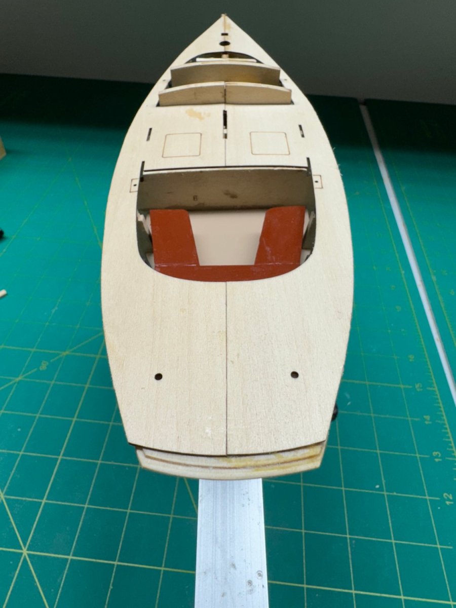
Painted seats installed. I also painted the cabin floor. Seats - badger 16-419 Umber. Cabin Floor - Badger 16-427 Salmon Buff
- 88 replies
-
- 3
-
-
- Muscongus Bay Lobster Smack
- Finished
- (and 1 more)