cdrusn89
-
Posts
1,918 -
Joined
-
Last visited
Content Type
Profiles
Forums
Gallery
Events
Everything posted by cdrusn89
-
 Since the instructions made a big deal about getting the seats aligned I decided to assemble them off ship and added a strengthener to ensure the three pieces were aligned. And yes, I originally painted the wrong side of one of the seat sides. i am pretty sure I checked before I painted but obviously I forgot to mark the backs and had to repaint. This goes on the hull shortly and then the "real fun" seeing how well the deck fits.
- 88 replies
-
- 2
-

-
- Muscongus Bay Lobster Smack
- Finished
- (and 1 more)
-
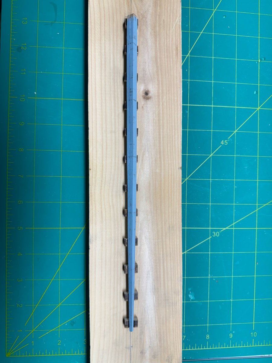
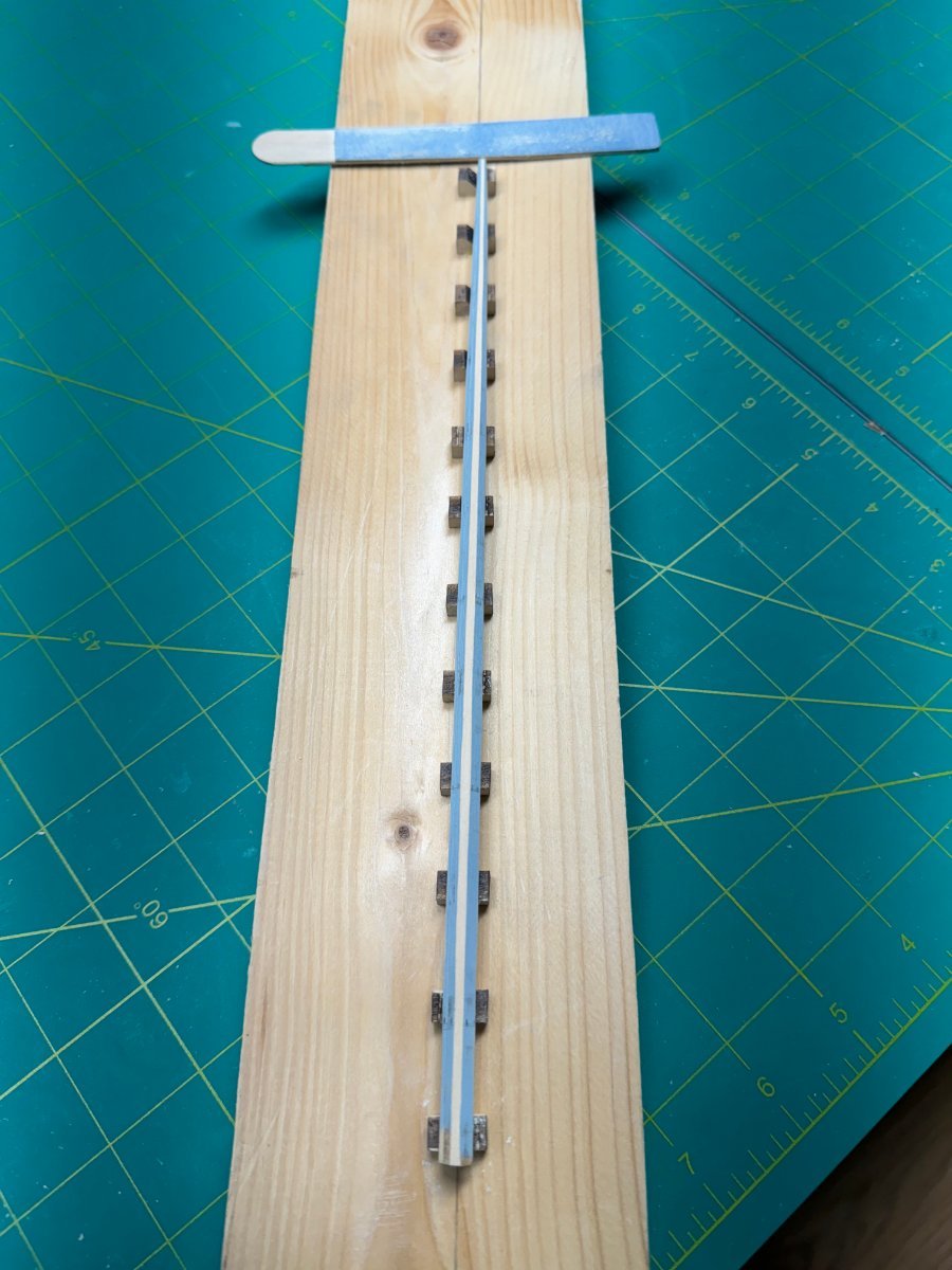
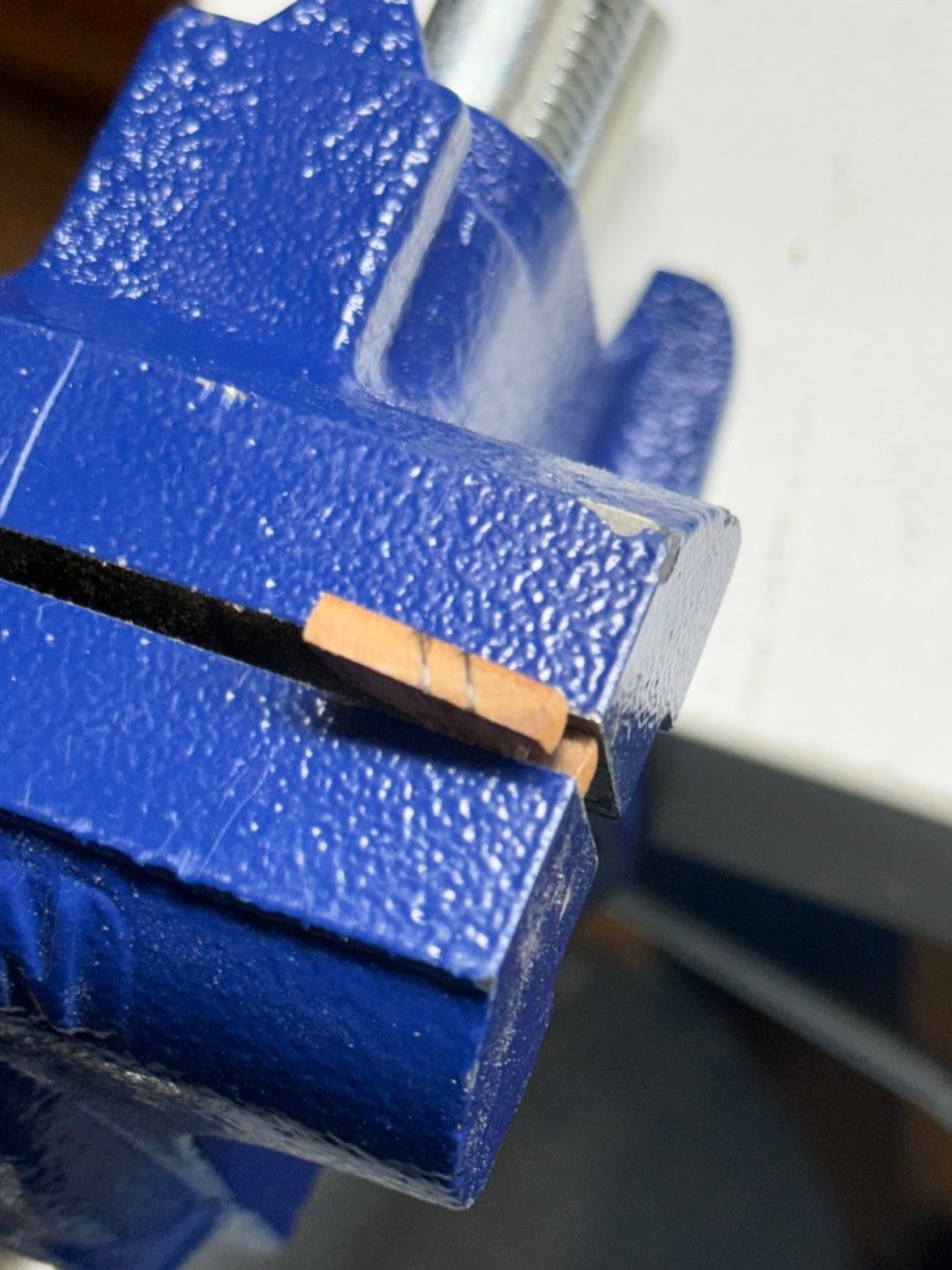
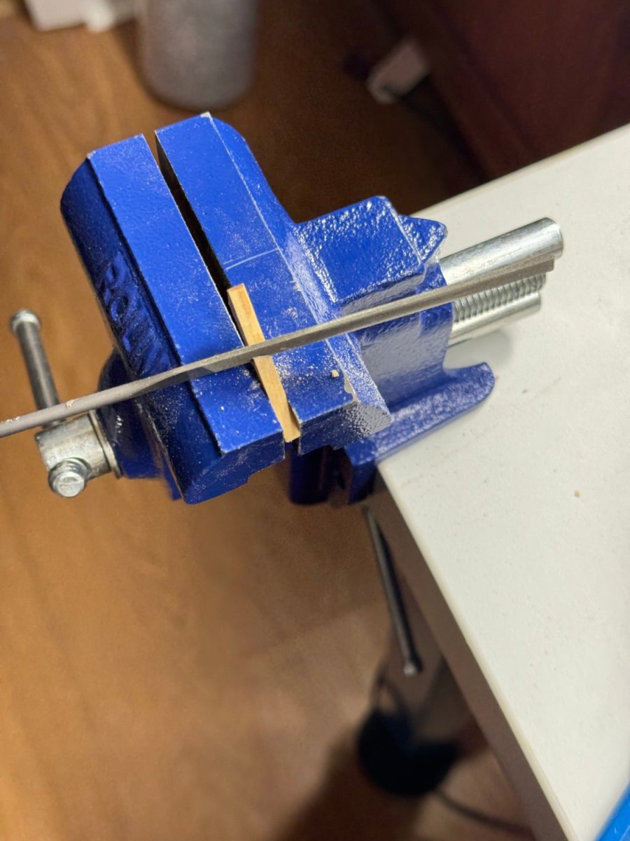
While waiting for the extra support glue to "really set" I went back to working on the mast. It would have been nice if when the two halves were glued together the lower end would have been square. As it was one side was 8mm across and the other was 6.4mm. Since I have one I used the Byrnes thickness sander to get the lower end square before working on getting the other two sides tapered. Tapering was not two big a challenge but drawing straight lines on relatively tiny pieces of wood has always been a challenge for me. After the mast was tapered on both sides I painted it with a water based gray primer. I find it much easier to work the spar to eight sided when I can see a distinct contract between where the wood has been removed and where it has not. I also cheated and built a "rounding board" with supports every inch covering 12 inches so even very long pieces can be supported along their entire length. Here is the tapered spar in the fixture. I use a sanding stick made out of a tongue depressor with 220 grit sandpaper glued to each side. I try not to use any sandpaper more aggressive than 220 grit because when I do generally bad things happen. I would rather spend ten minutes getting the correct amount of wood off rather than five minutes and take off too much. Besides it leaves a cleaner surface that is easier to finish sand. So here is what the spar looks like after the first side has been "flattened". I use the tic strip I prepared before hand to check the width of the bare wood and can see if the width tapers as it gets closer to the narrow end. At this point I can see that there needs to be more wood removed at the wider end but it looks pretty good where the taper starts. After some more work on this side and the next here are the upper and lower ends: And here it the completed eight sided mast in the fixture with the tool of choice at the top.


- 88 replies
-
- 4
-
-
- Muscongus Bay Lobster Smack
- Finished
- (and 1 more)
-
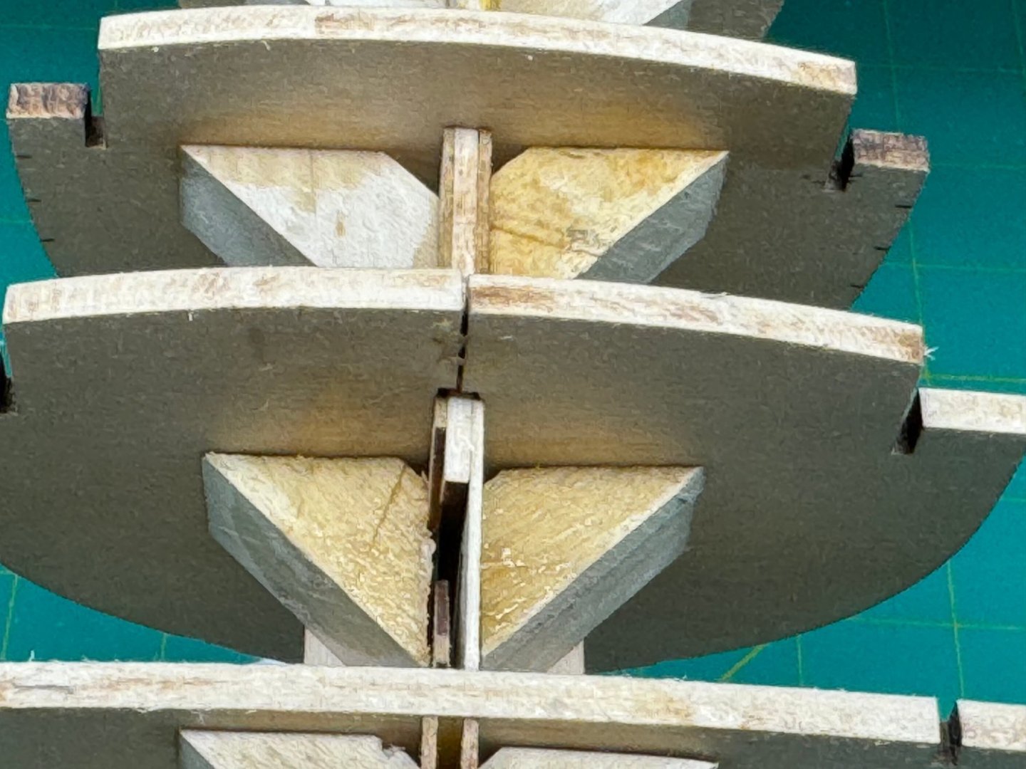
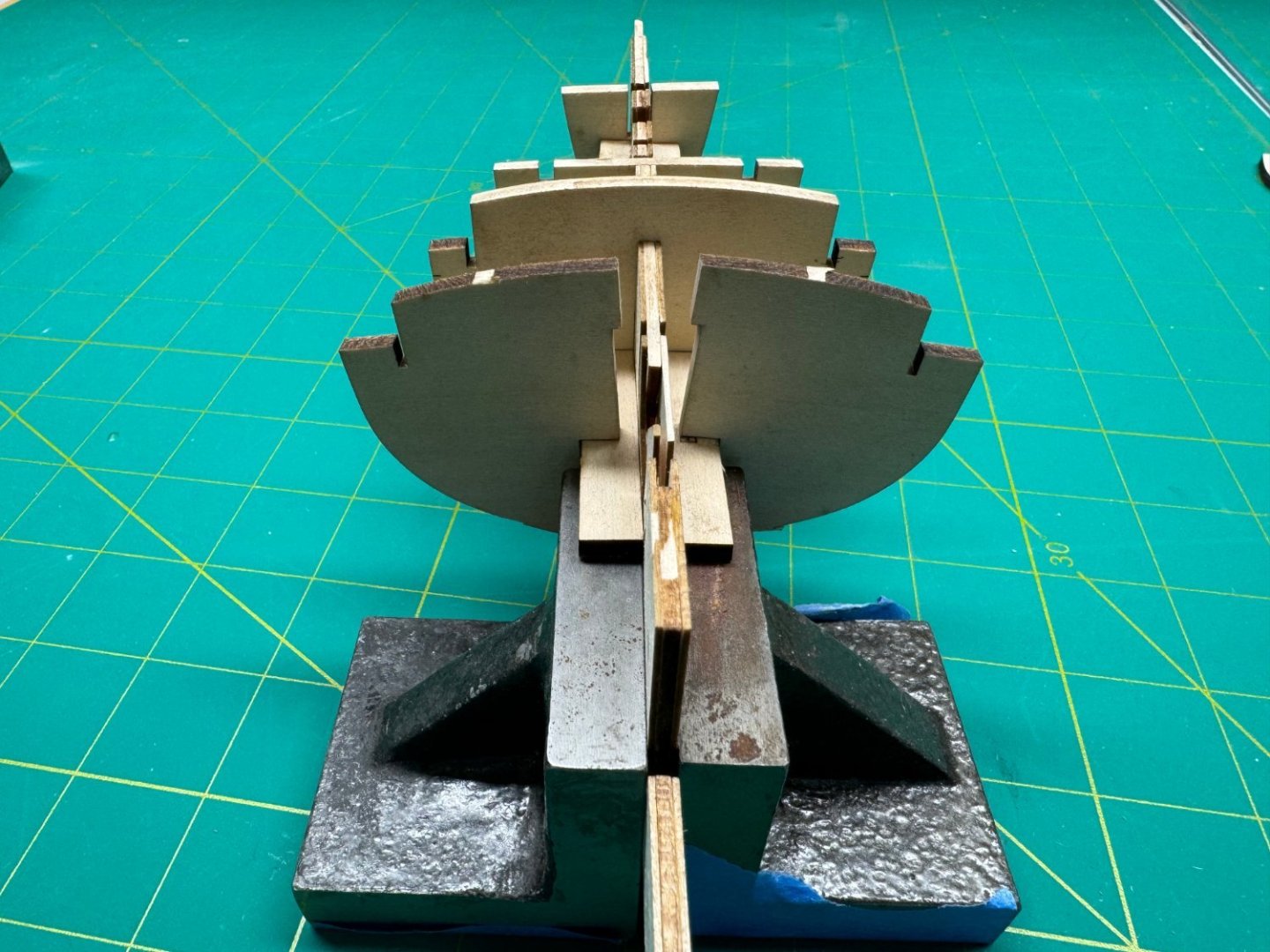
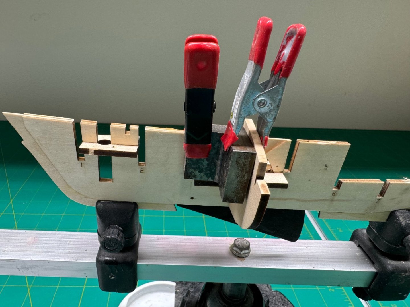
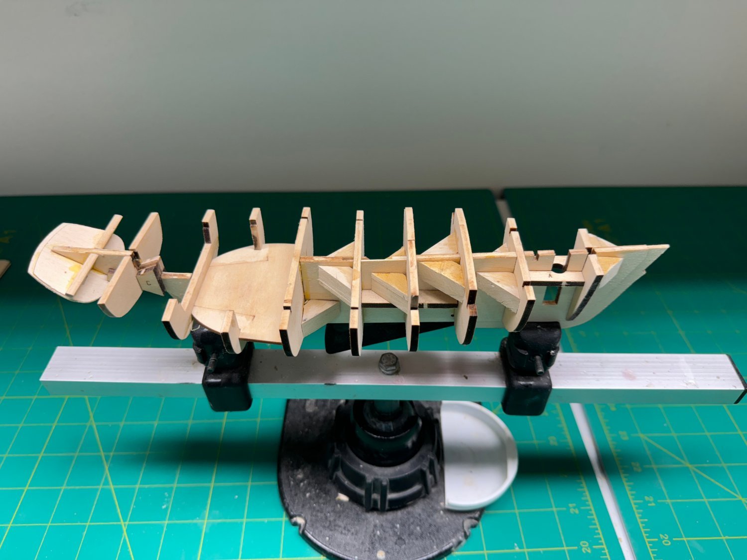
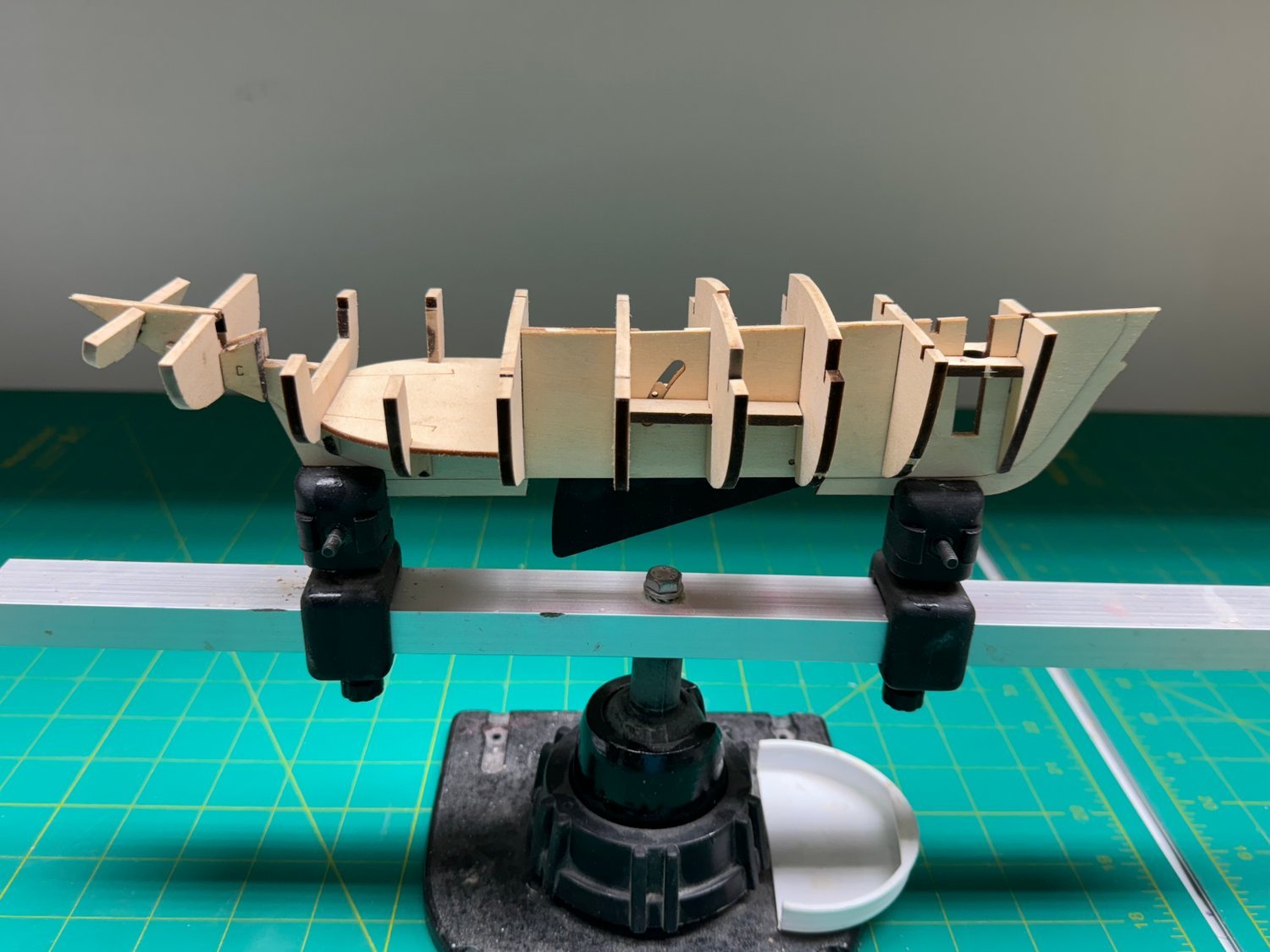
Yes, bulkhead four came together at the spine. I experienced some unease and trepidation once I had the bulkheads (and floor) glued in place. It may all have been optical illusions caused by all the lines on the cutting pads or my eyesight not being what it used to be (along with many other functions) but I thought it prudent to add some additional support between the bulkheads to keep them perpendicular to the spine. While the "spinal rigidity" leaves something to be desired (IMHO) there isn't anything I can think of that will help that appreciably. So I added some perpendicular supports between the bulkheads where I could get access. Sadly there doesn't appear there is room/access to do anything for bulkheads nine and ten so we will have to be "particularly careful out there" to quote an old TV show - anyone remember the show and character???? So here is the hull framework with the supports added. I put some sanding sealer on the cabin floor as I intend to paint the cabin floor and seats before everything comes together in that area.


- 88 replies
-
- 4
-
-
- Muscongus Bay Lobster Smack
- Finished
- (and 1 more)
-
Thanks Rusty, Ryland and nzreg. Working the Muscongus Bay Lobster Smack now waiting for the HMS Speedwell from Syren to come "on line".
- 389 replies
-
- 3
-
-
- winchelsea
- Syren Ship Model Company
- (and 1 more)
-
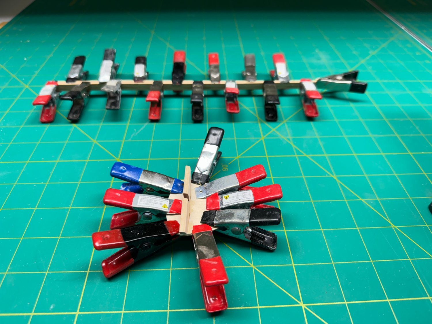
While waiting for the glue on bulkhead 4 (second half) to dry I looked ahead and glued up the stern transom and the mast halves. I will continue the mast shaping in between bulkhead gluing.

- 88 replies
-
- 5
-
-
- Muscongus Bay Lobster Smack
- Finished
- (and 1 more)
-
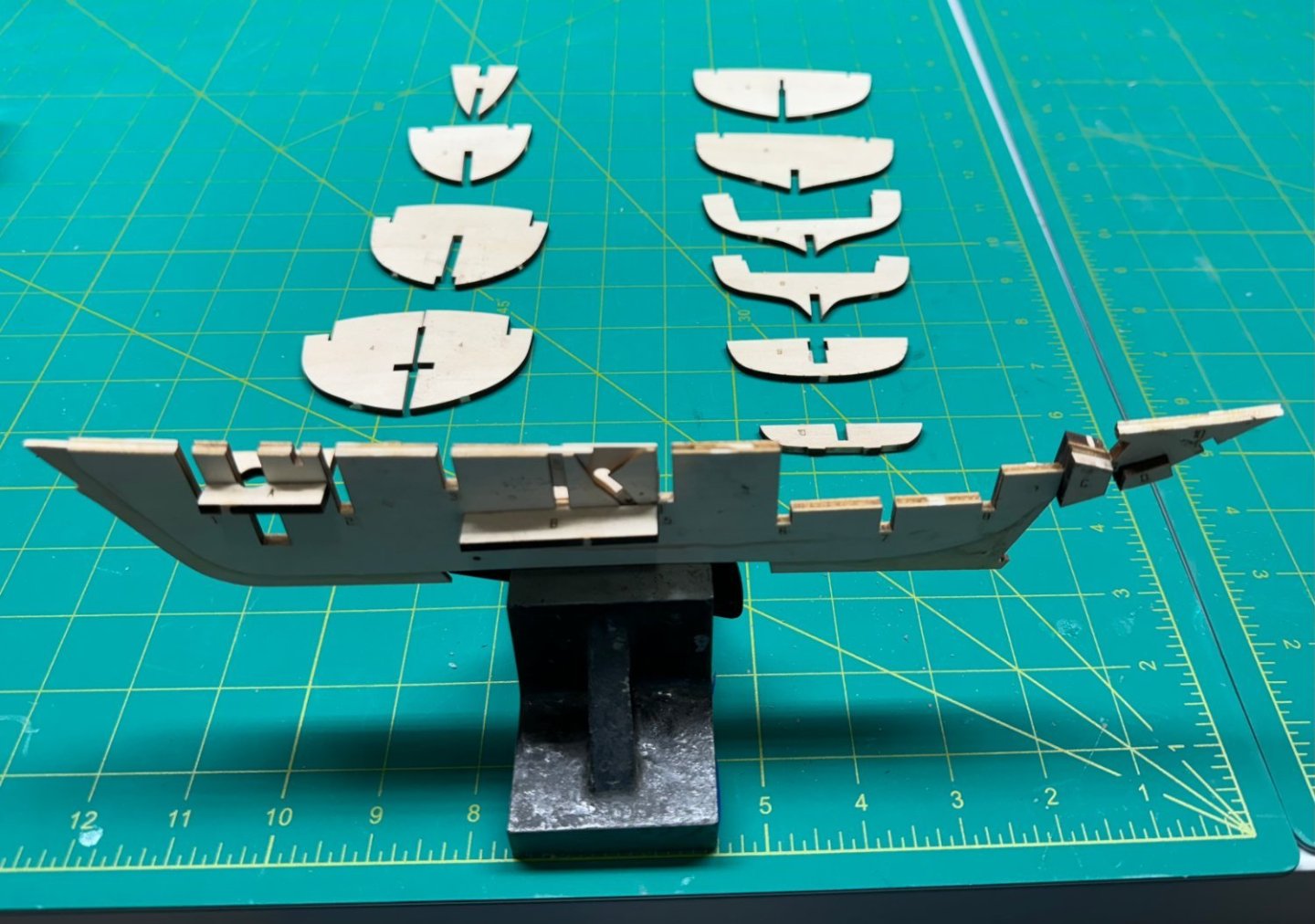
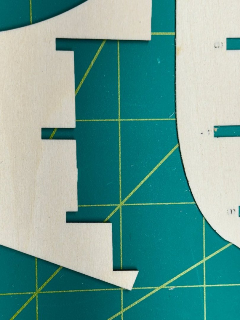
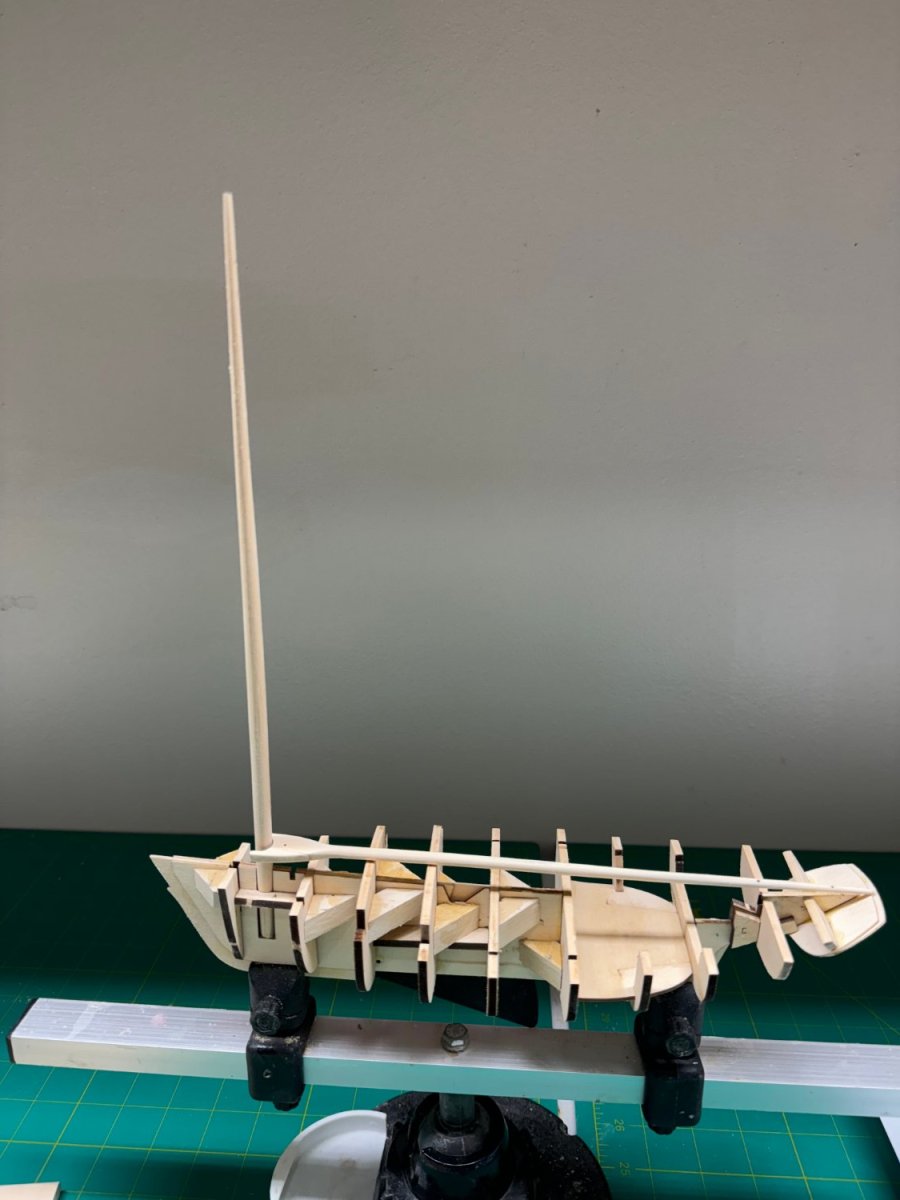
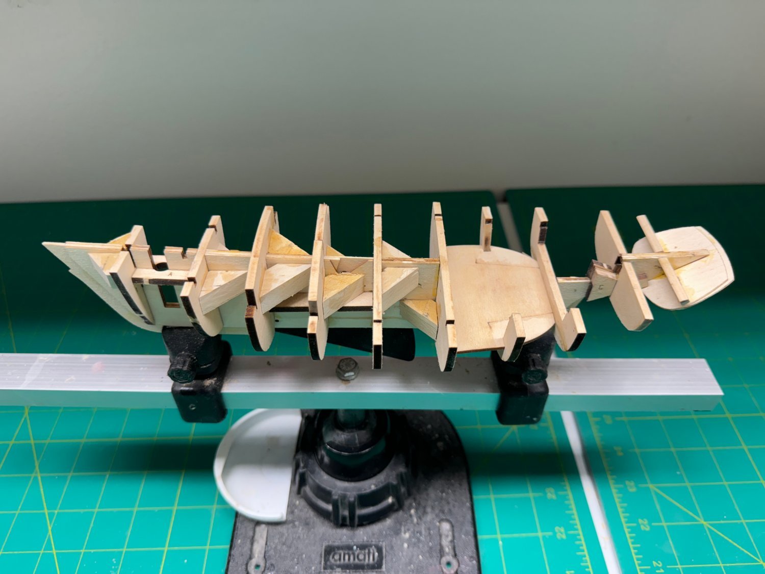
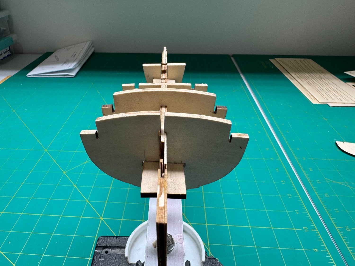
Dry fitting went fine until bulkhead 4, the one that is in two halves to accommodate the centerboard trunk. Well, I did have to trim the bottom of bulkhead 1 as it stuck down below where the garboard plank will be. But Bulkhead 4 was definitely a problem. The notches to fit over the spine stiffeners are definitely too shallow. I measured and then cut out the offending parts. And that seems (after some more cutting, sanding and fitting) to resolve the issue. So here are the ten bulkheads and cockpit floor dry fit into the spine. And here is the first half of bulkhead 4 glued into the spine waiting for the glue to set.


- 88 replies
-
- 5
-
-
- Muscongus Bay Lobster Smack
- Finished
- (and 1 more)
-
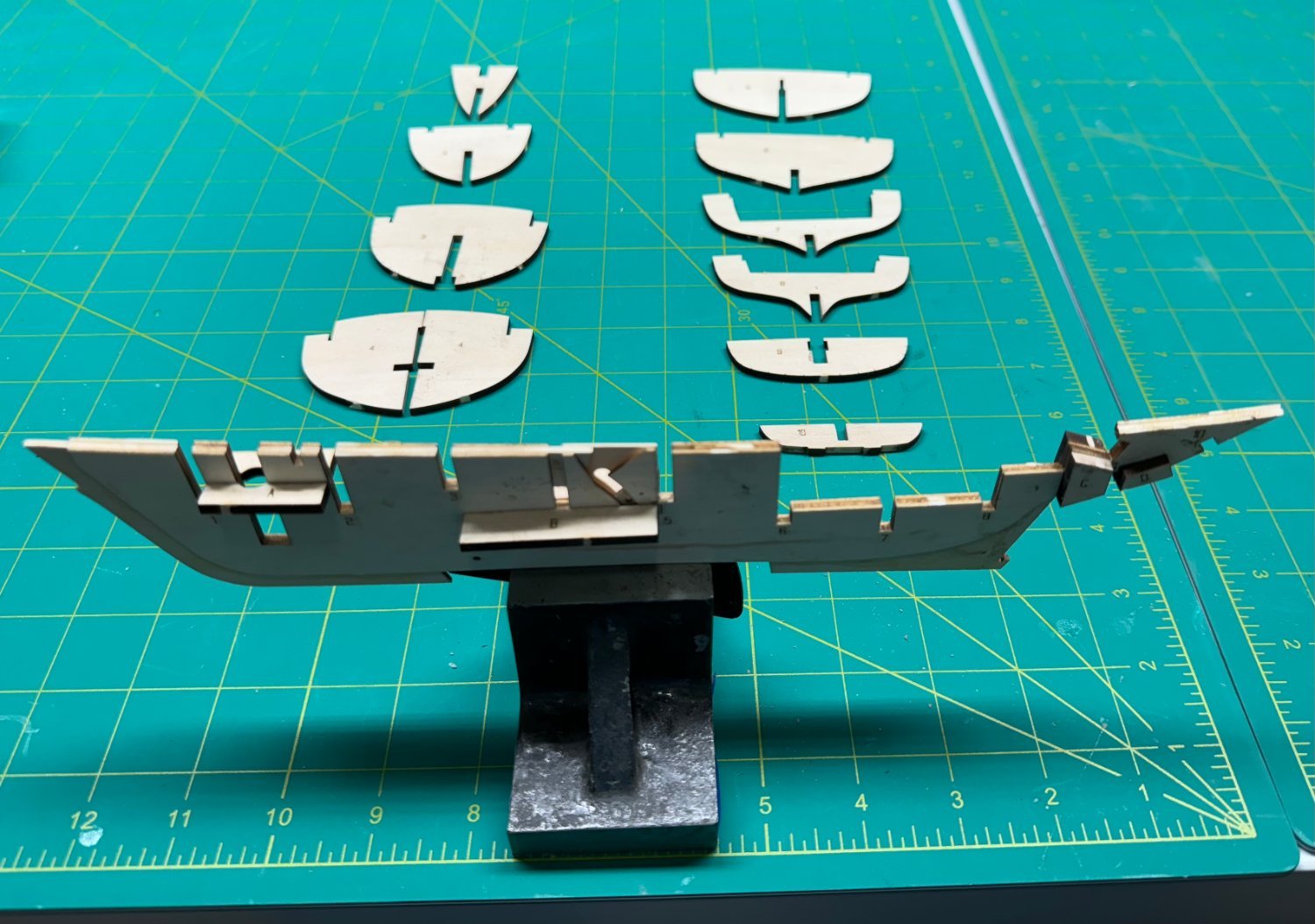
I decided on a fixed centerboard in the down position so I painted the exposed portion flat black before gluing it onto the spine pieces. It may make a handy place to hold the structure for now. I managed to get the center spine and reinforcements attached without major problems. I used Titebond yellow glue for the spine but resorted to medium CA for the reinforcements. I find it easier to get precise location with the CA. I removed the bulkheads and cleaned the char from the slots as directed. So here is the center spine and the bulkheads ready for dry fitting.
- 88 replies
-
- 4
-
-
- Muscongus Bay Lobster Smack
- Finished
- (and 1 more)
-
Thanks Jacques. As they say on TV "Details Matter".
- 88 replies
-
- 1
-
-
- Muscongus Bay Lobster Smack
- Finished
- (and 1 more)
-
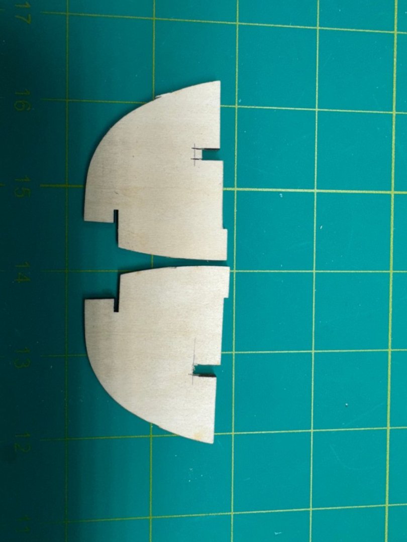
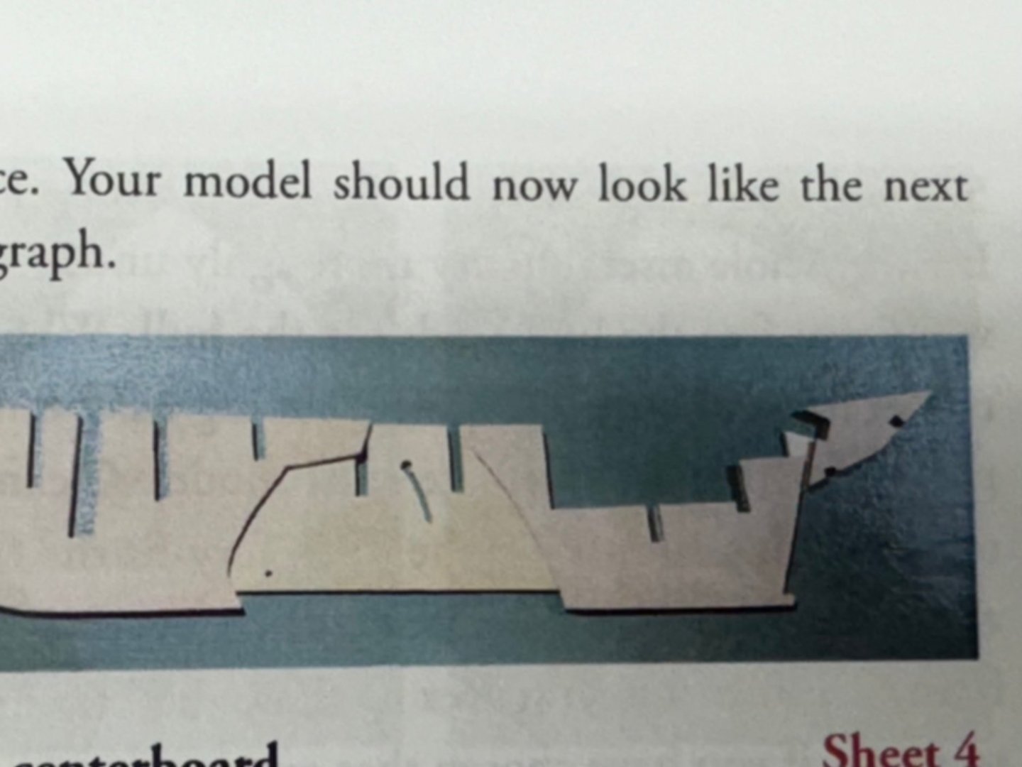
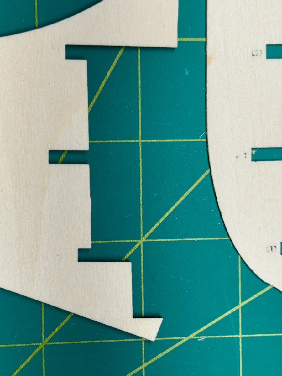
The first issue I encountered is there is a discrepancy between the center bulkhead pieces shown in the instructions and the material actually provided. I canot tell if this is going to be a problem but... This is the middle center section: On the left you can see three "notches" probably where bulkheads will be placed after the spine is completed. Here is a picture from the instructions which shows only two such notches. Probably better too many in actuality than too few but...
- 88 replies
-
- 1
-
-
- Muscongus Bay Lobster Smack
- Finished
- (and 1 more)
-
While waiting for the HMS Speedwell project from Syren Ship Model Company I am building some smaller models to "fill in the spaces" in some of the cabinetry where the larger models will not fit.
-
Thanks Rick and Dusan. The long boat is the Model Shipways 18th Century Long Boat kit (MS1457CBT). It was the only 1/48th scale ship's boat I could find. I would have put two on (like the Confederacy model) if I could find one a slightly different length than the Model Shipways kit.
- 389 replies
-
- 3
-
-
- winchelsea
- Syren Ship Model Company
- (and 1 more)
-
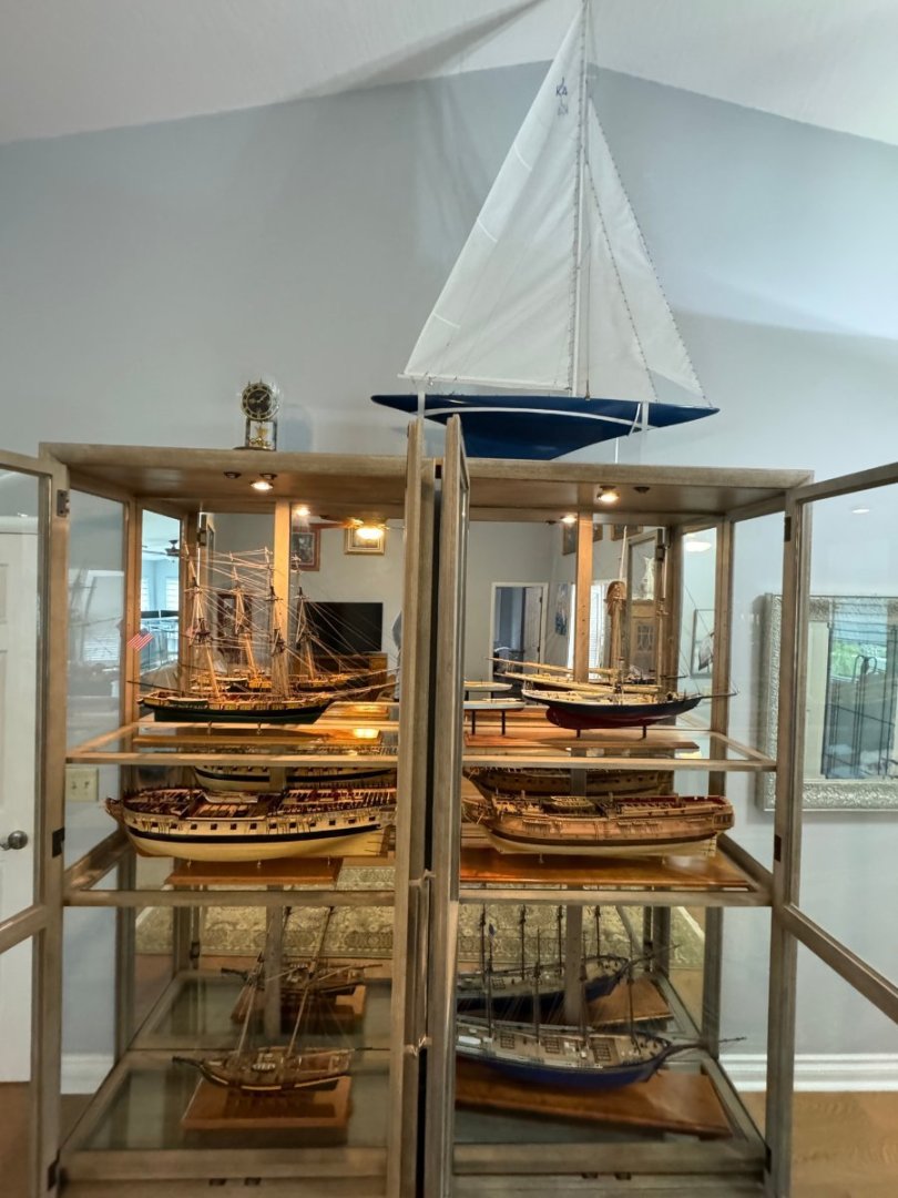
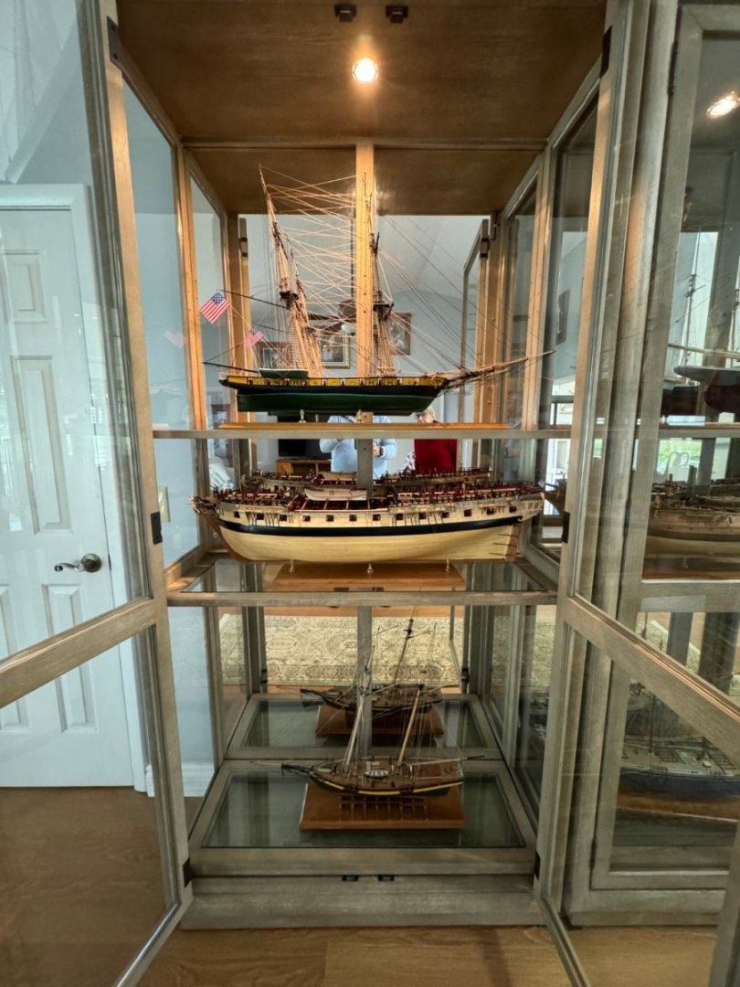
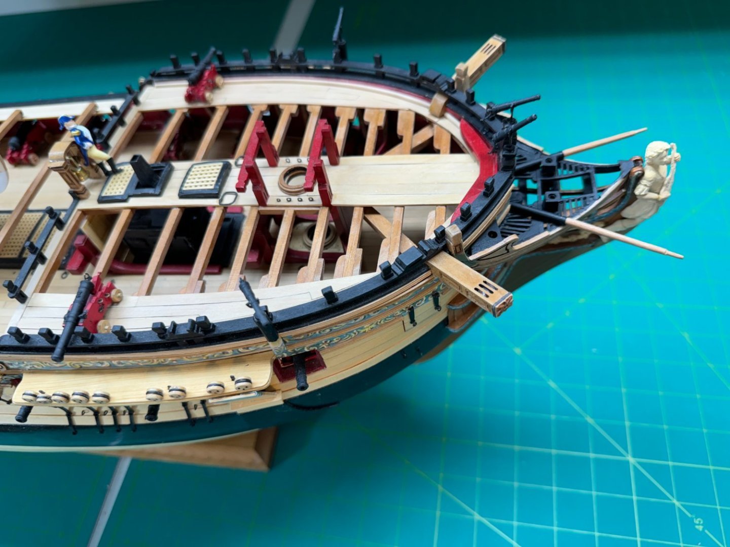
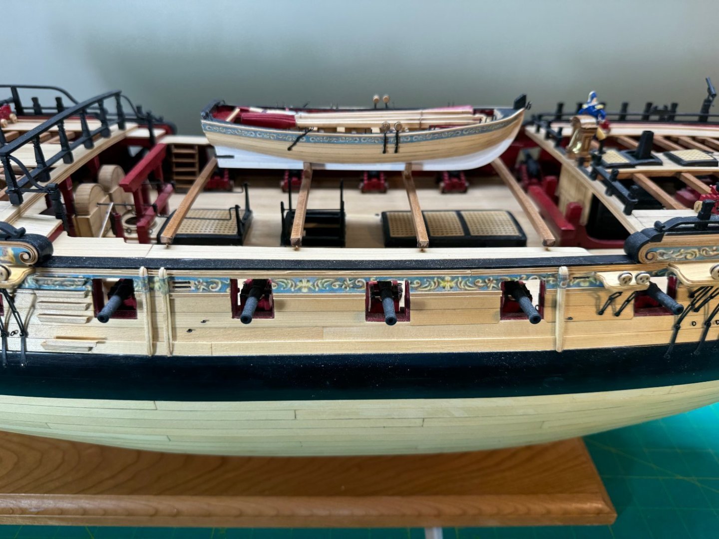
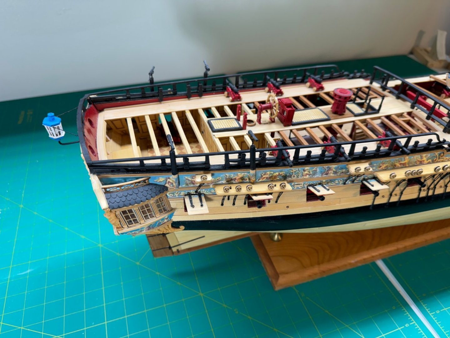
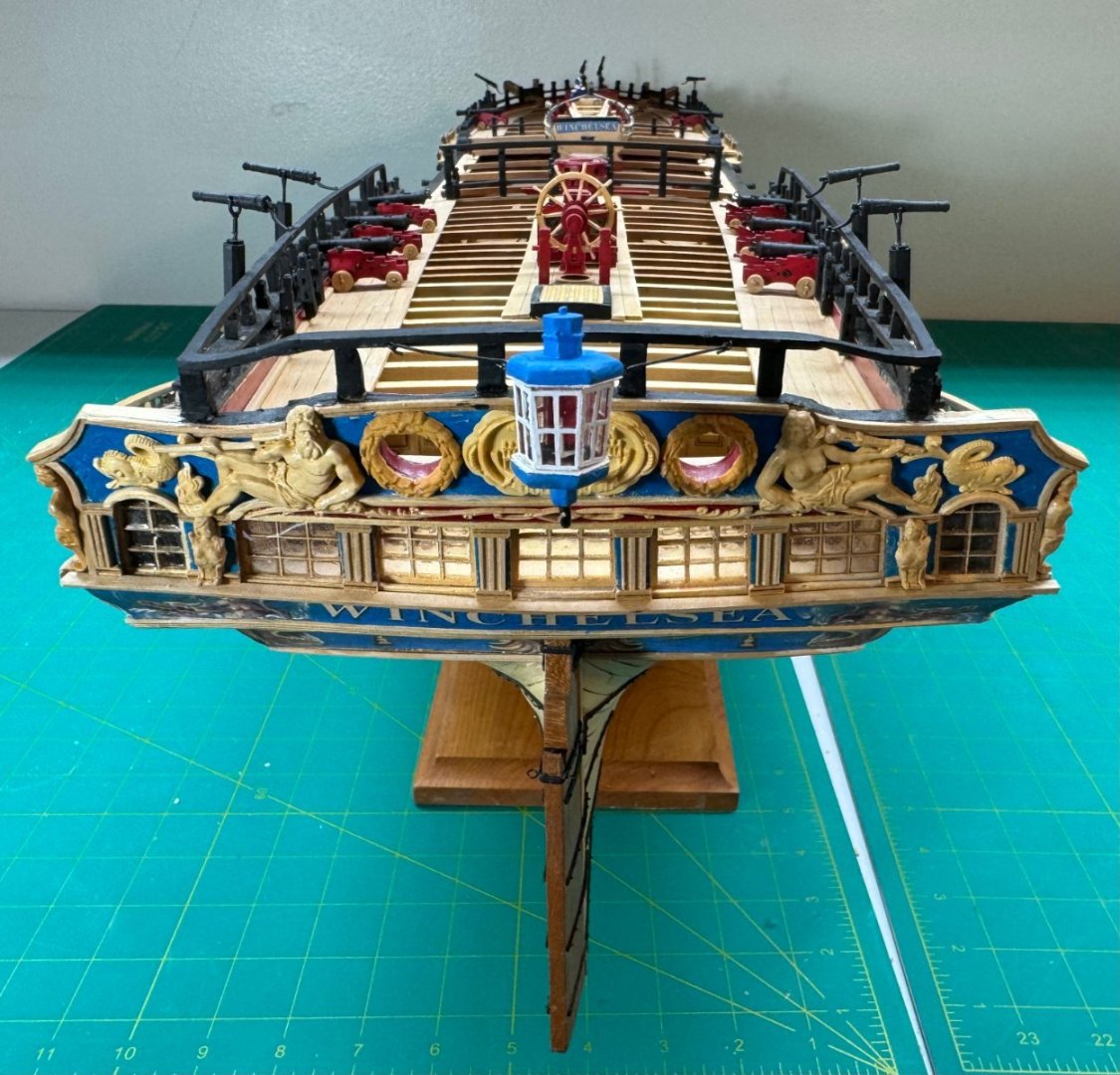
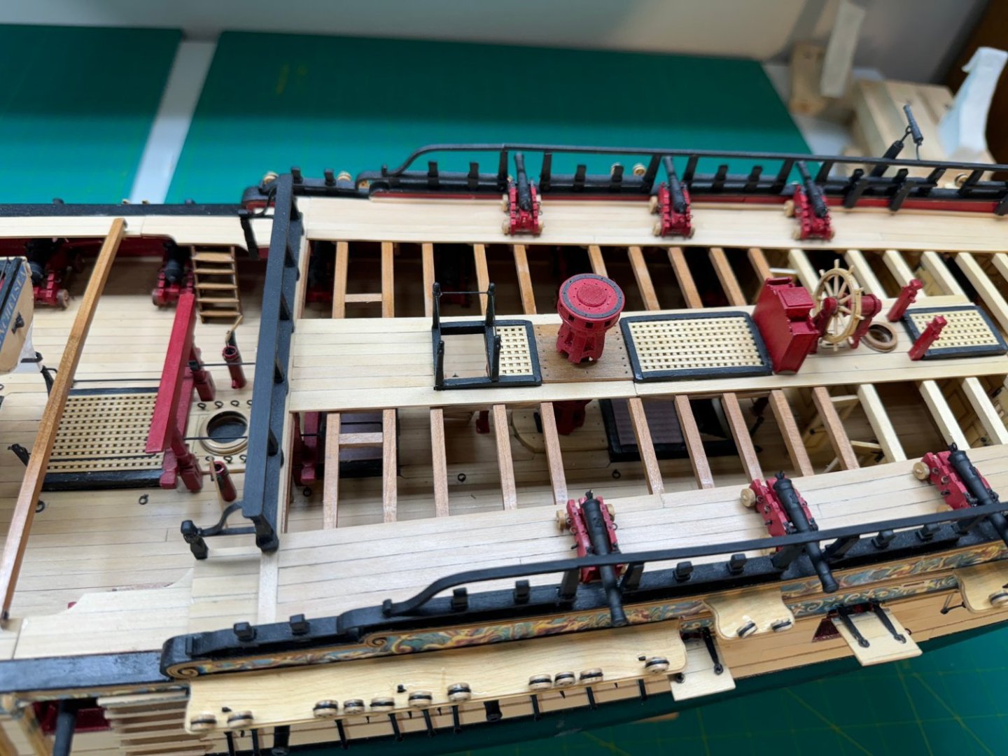
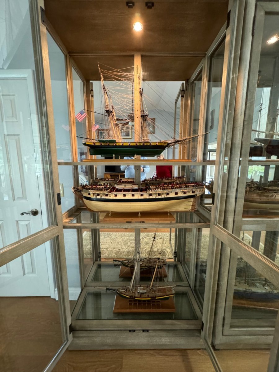
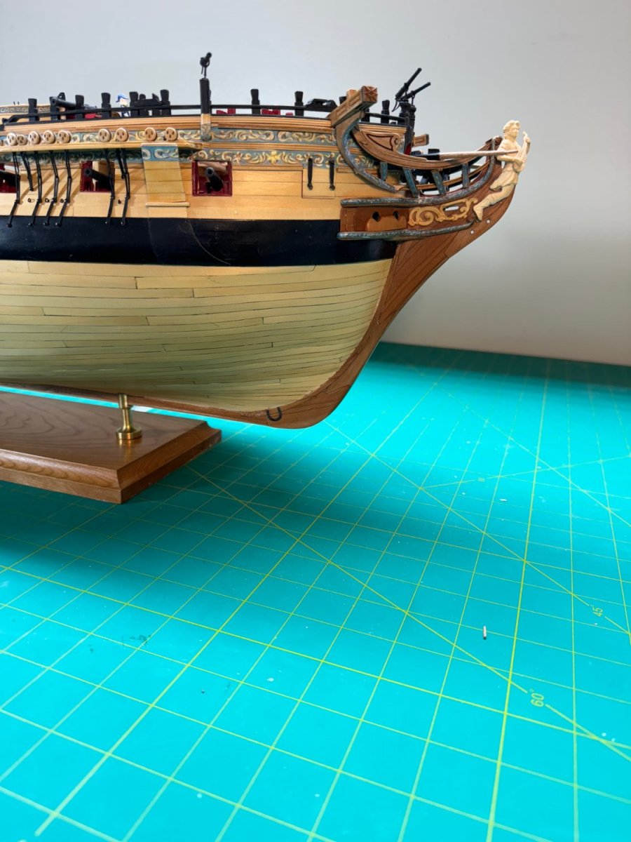
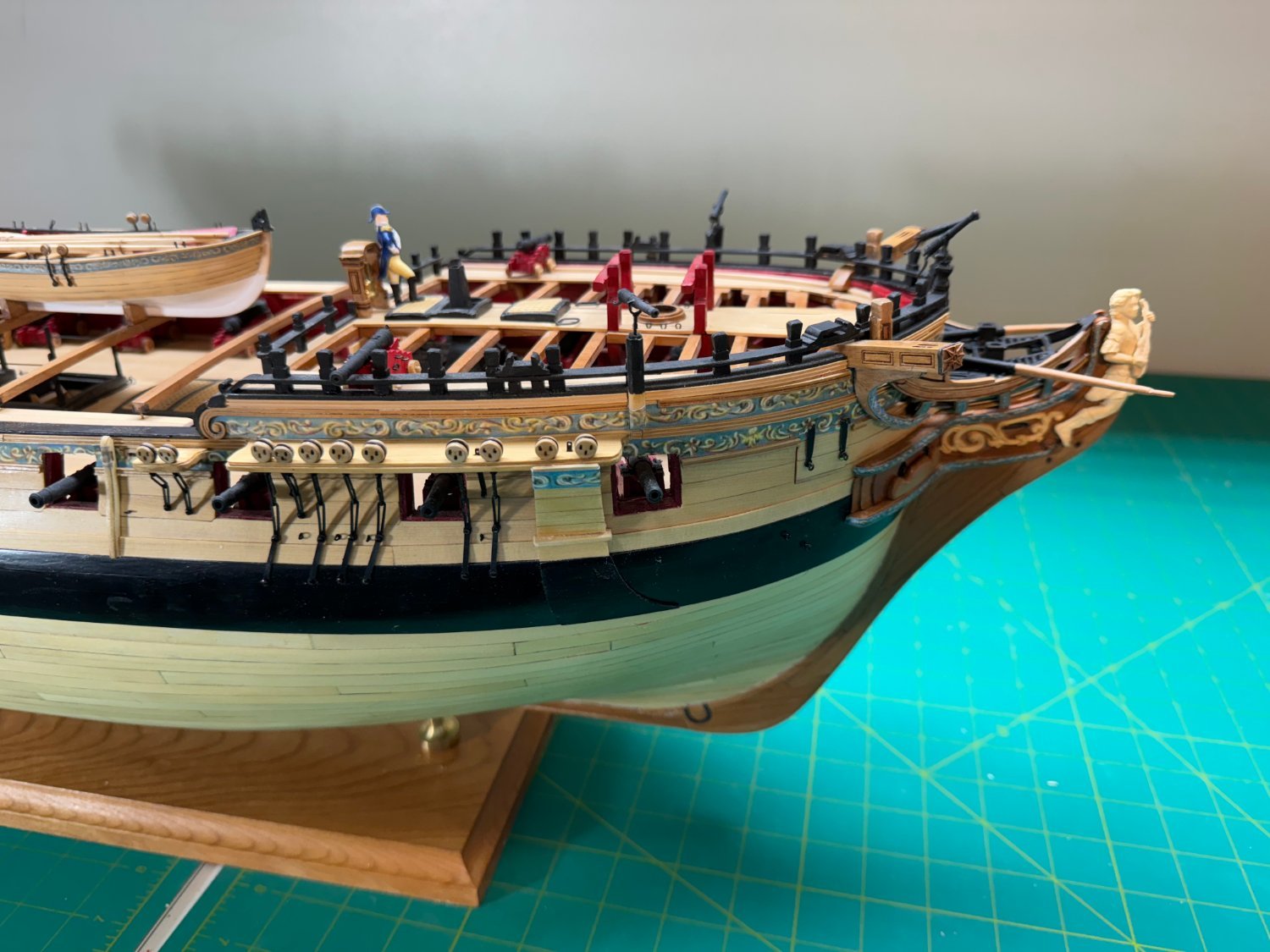
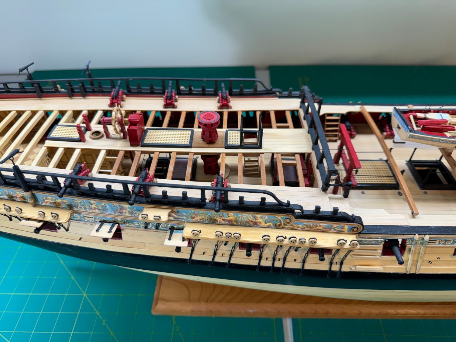
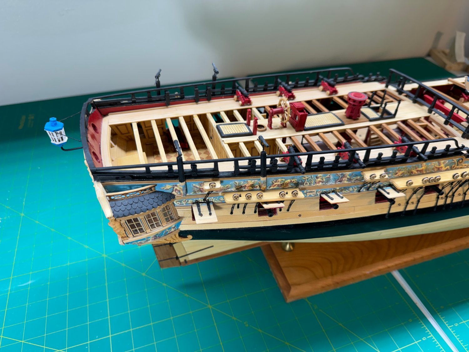
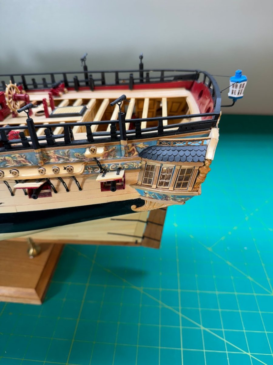
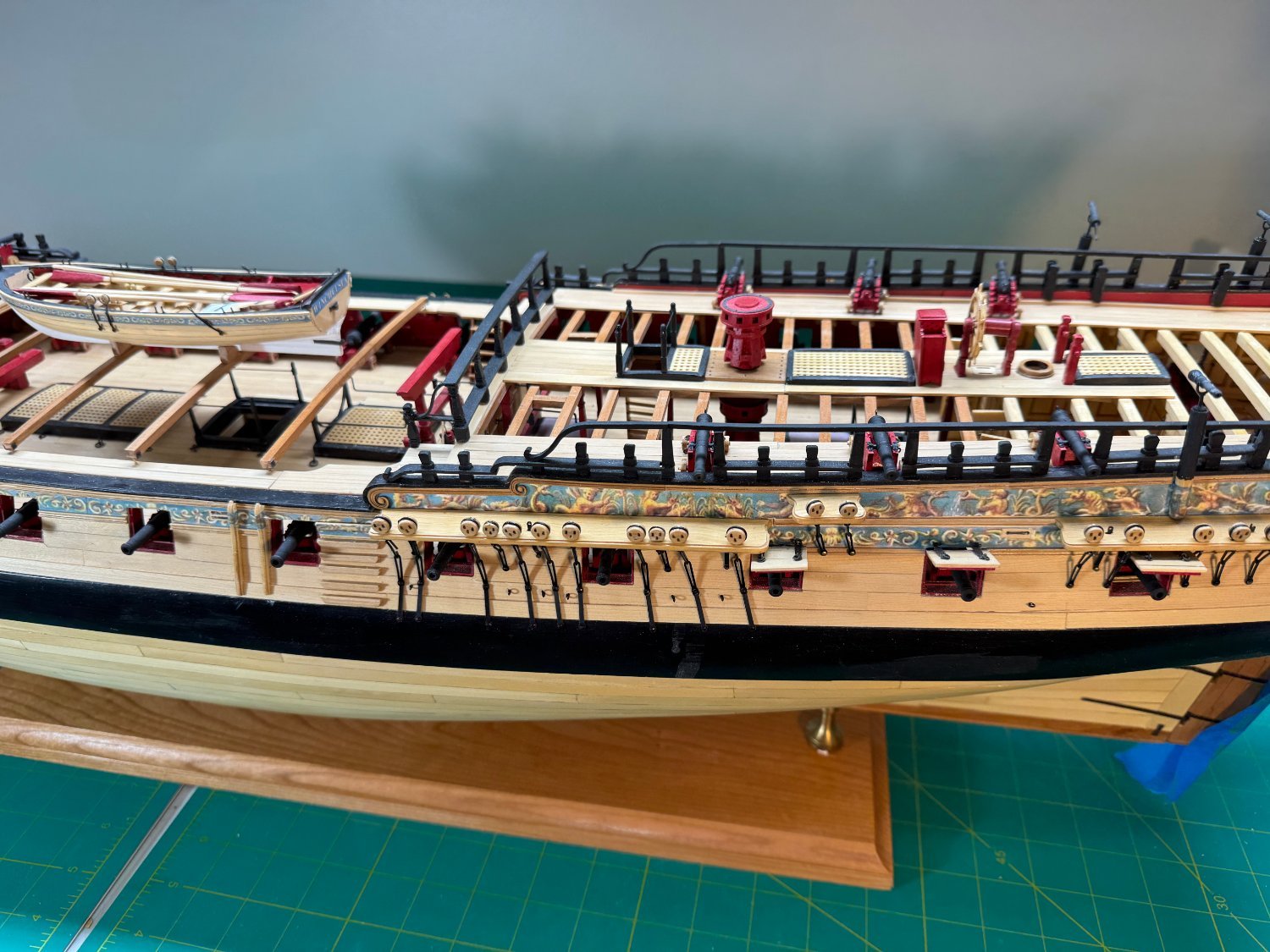
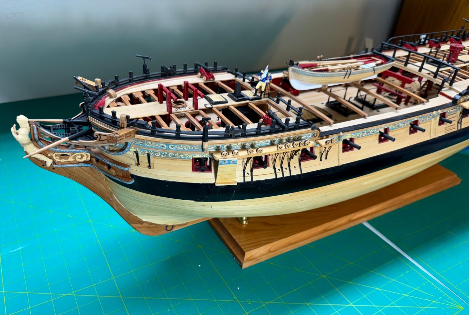
My Winnie is FINISHED!!! I would update the blog title to reflect that if I could remember how to do that - once every 12 - 18 months is not frequent enough to get that in the long term memory - it least at this age it is. Here are a bunch of pictures before she goes in the display cabinet. And here she is in her new home. And here is the fleet - or most of it anyway.


- 389 replies
-
- 16
-

-
-

-
- winchelsea
- Syren Ship Model Company
- (and 1 more)
-
First round of touch-up paint done and the false rails are on. I decided to leave the rails natural except for the inside esurface which I painted black. And I opted for no frieze. I have the other two heads, the bumpkins and the stern lantern left to go. I already have the stern lantern built so it in just mounting that is required. Plus I almnost forgot the elm tree pumps - I did not install them previously due to damage possibility but now seems like a good time to get them in place. By the way does anyone know where, exactly the bumpkins go. I can't find them on any of the drawings and the monograph only shows them in a few pictures.


- 389 replies
-
- 6
-
-
- winchelsea
- Syren Ship Model Company
- (and 1 more)
-
Starboard side head timbers (all 4), cat head support and middle rail completed. Head gratings (except for the ones outboard of the heads) completed but much paint touch-up required. I will wait until I get the last for grating pieces in place then (hopefully) get all the black touch up at once. Getting close to the finish line now! FYI - while the monograph says there are plenty of grating pieces to do all that is required I must be a paragon of wasteful as I used almost twice what came with the Chapter 12 materials. Just saying.


- 389 replies
-
- 8
-
-
- winchelsea
- Syren Ship Model Company
- (and 1 more)
-
Starboard side head timbers and associated "stuff" completed. On to the port side and then the Head gratings and REALLY small thin pieces.

- 389 replies
-
- 8
-
-
- winchelsea
- Syren Ship Model Company
- (and 1 more)
-
Starboard side cat head support in place and frieze applied. On to the fourth head timber. and yes, I fixed the frieze at the top before the glue was completely set.

- 389 replies
-
- 7
-
-
- winchelsea
- Syren Ship Model Company
- (and 1 more)
-
Cover boards on starboard side installed. The Cat Head support knees are causing me a significant level of difficulty. I decided to get the starboard side completed on the cover boards, cat head support and the fourth head timber before I start the port side. I am on my third attempt at the upper portion of the cat head support on this side. Can't afford another without more materials.
- 389 replies
-
- 7
-
-
- winchelsea
- Syren Ship Model Company
- (and 1 more)
-
Head timbers are in place. Now the lower rails which I hope I have correctly templated before committing to adjust the "real" rails. Then the cover boards and some touch up painting and filling the hole in the middle timber.


- 389 replies
-
- 8
-
-
- winchelsea
- Syren Ship Model Company
- (and 1 more)
-
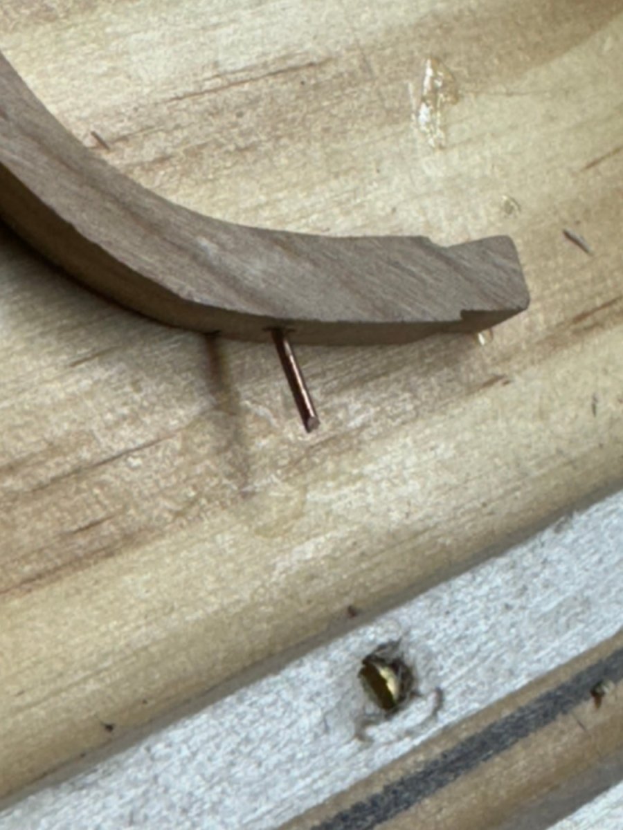
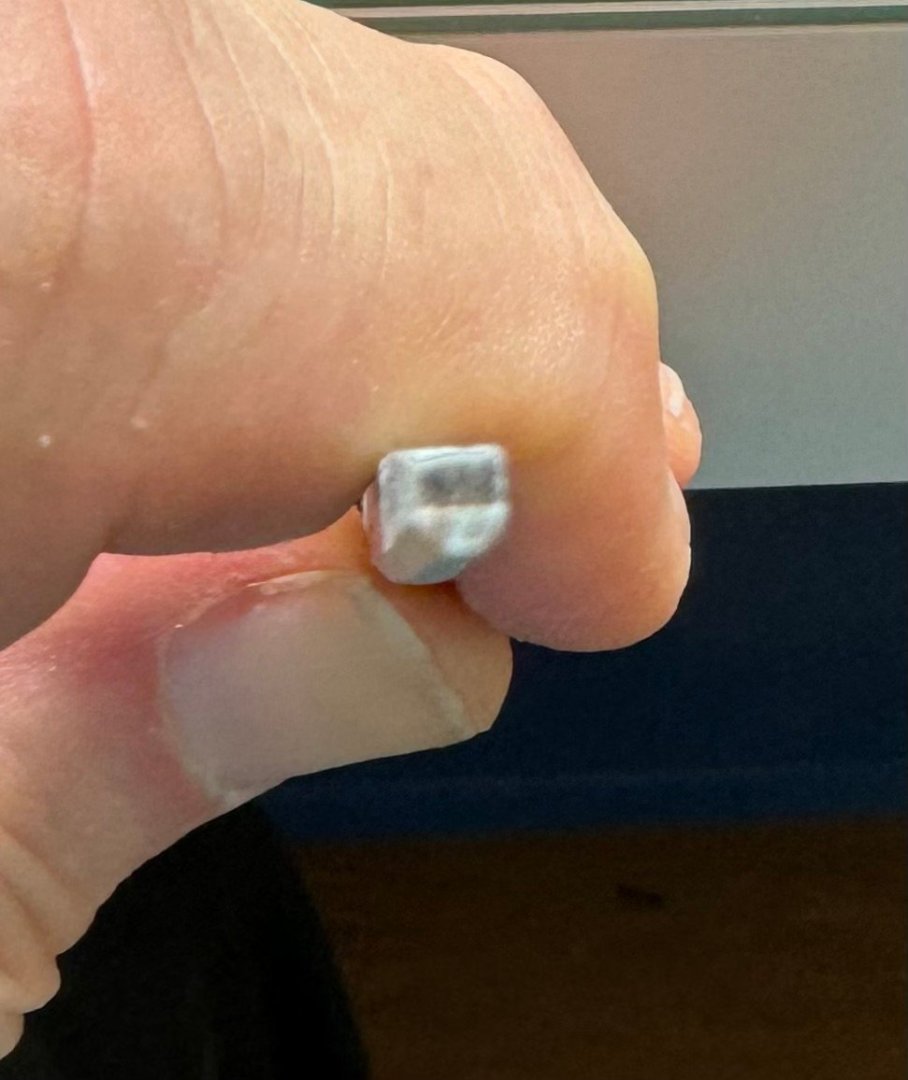
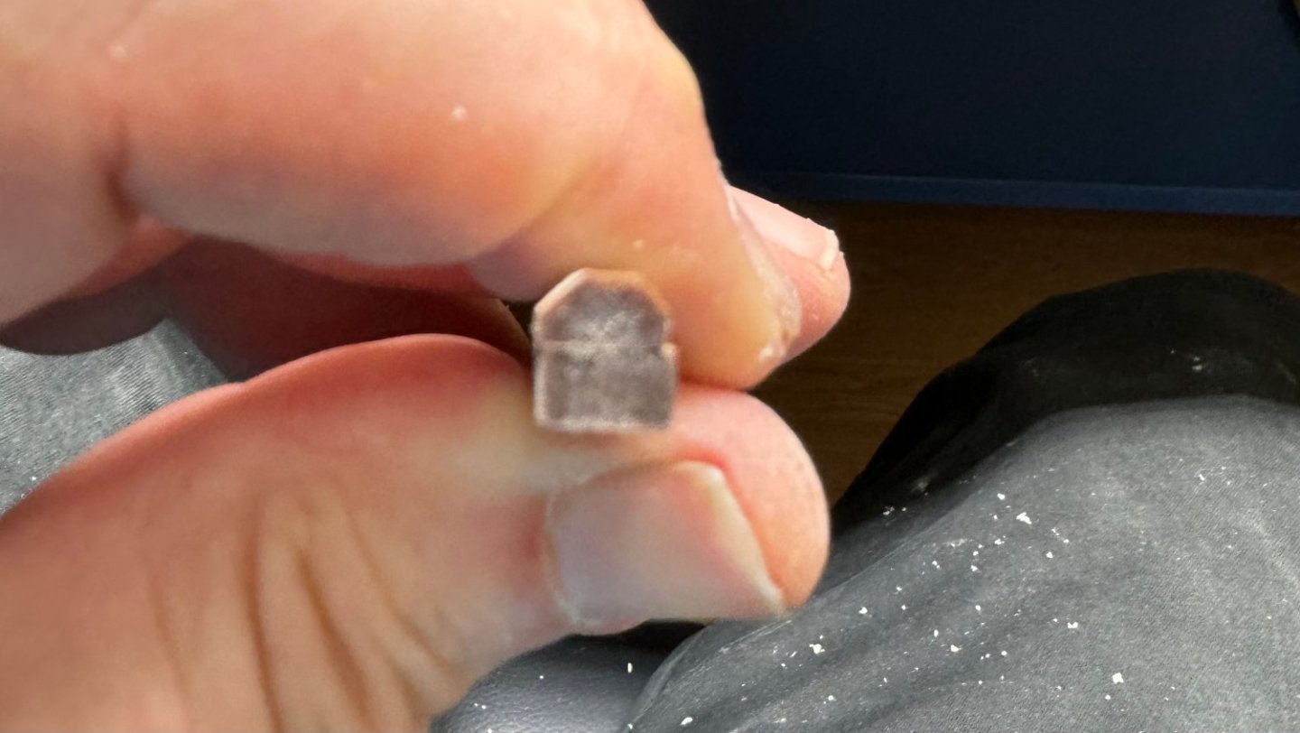
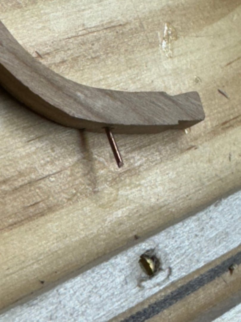
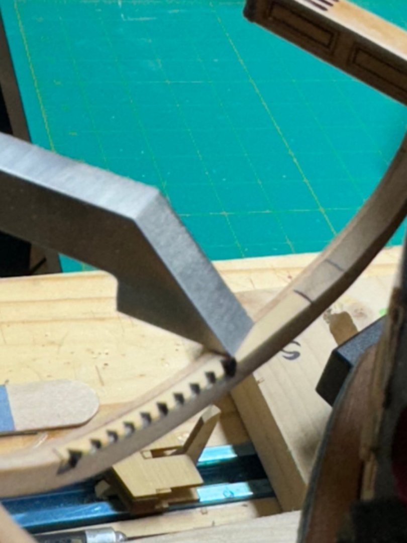
Head Timbers - what fun. Given my previous less than successful use of rubber cement I decided to try another approach. I located where the provided head timber template would locate the forward two timbers and added a .032 phosphor-bronze pin there. Then I drilled .032" holes in the center of each head timber and used these to locate the head timbers while trying to get them to fit under the head rails. I fitted the port side aft timber and then the starboard side aft because it just made life much easier with only one variable (the height of one side of one head timber) to change during each of what was probably several dozen "fittings. With one side of one timber finished I moved to the other side of that timber, another few dozen fittings then rinse and repeat for the forward timbers. One word of caution - with the beveling and notching of the timbers they become somewhat fragile. Probably why Chuck included three sets of each. Anyway, I finally deviated from the instructions and cut the notches before I did the beveling. To cut the notches I followed the instructions to get the "line" of the notch across the edge of the timber and then tried to line that up in the vise so that I was cutting as close to vertically through the timber as the size of the piece and the configuration of my vise would allow. This made it easier (for me) to keep cutting down the notch on both sides. I used a very fine flat needle file cutting on the file edge which was very close to the notch width. The picture above is of the after head timber as my photos of the others being filed did not turn out as well as I had hoped. So here is the forward head timber after the notches were cut but before the beveling. I have all three sets of timbers fitted (pending one final review) and in the "paint shop" so should have them ready for "installation" shortly.


- 389 replies
-
- 6
-
-
- winchelsea
- Syren Ship Model Company
- (and 1 more)
-
JJ - sign me up as an admirer. I have two Vanguard models (Speedy and Sphinx) lined up behind Winnie but would work Portland in as soon as it is available.
-
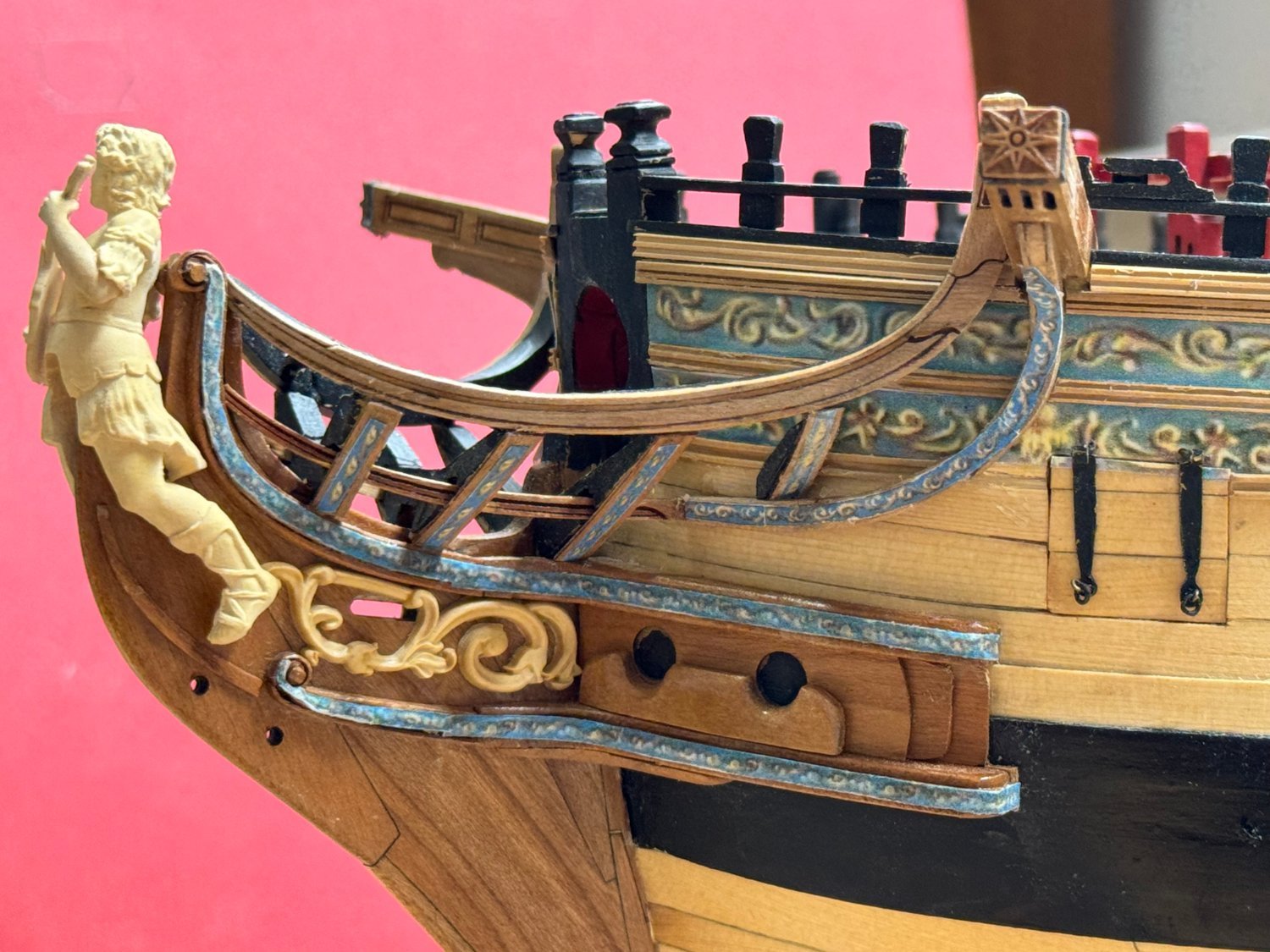
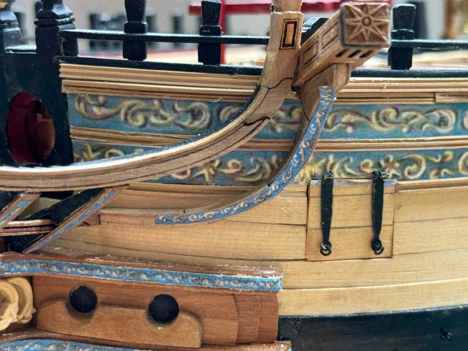
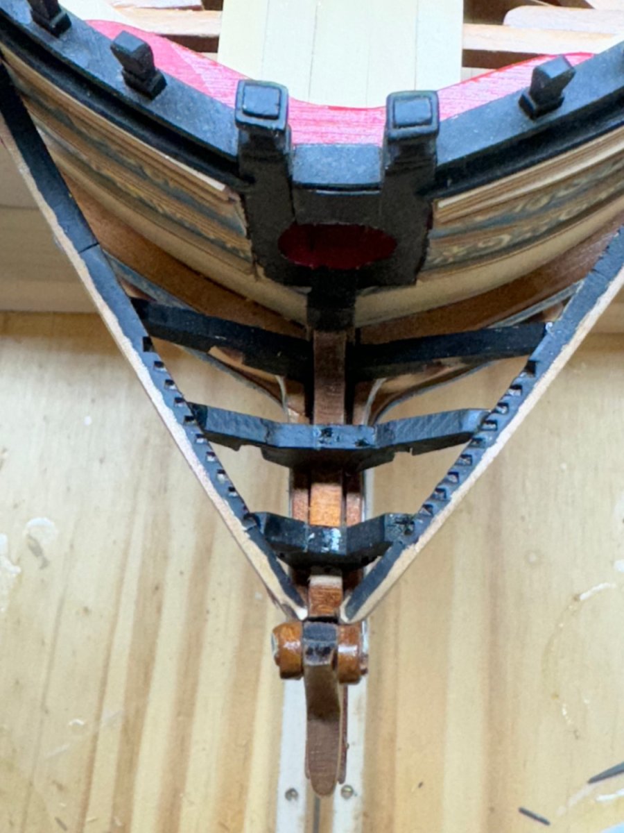
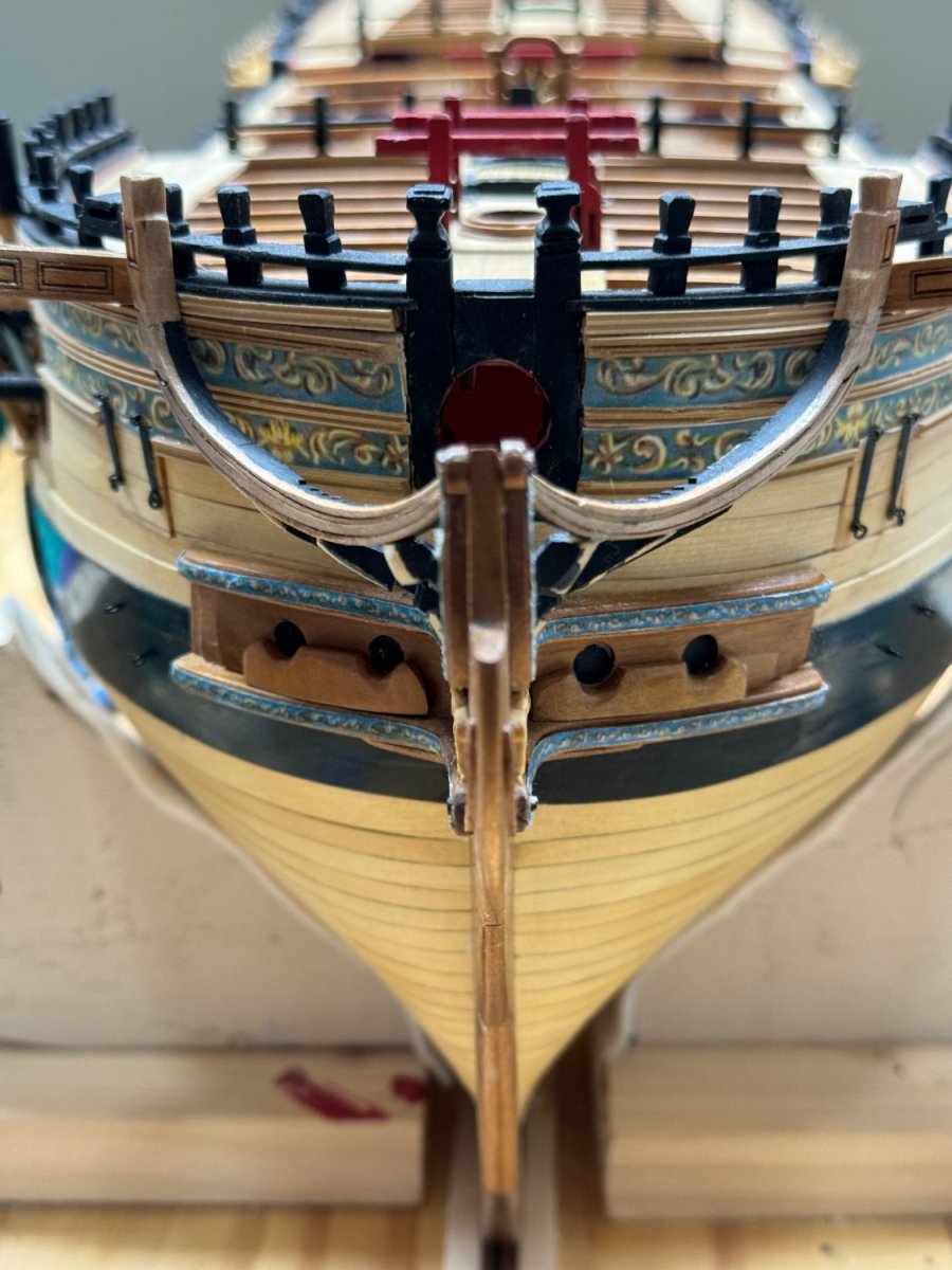
Thanks JJ - yes, down to all the "fun" head rails and such. Happy New Year to you as well. I got the head rails assembled per the instructions- since I have both the Cherry and AYC materials I put both sets together even though I plan on using the Cherry - the AYC was "practice". Once they head rails were assembled, char removed and thinned per the instructions I tried fitting them to the hull. It took a bit of "fiddling" with the forward end to get them to fit at the stem and I removed part of the fancy molding but eventually I got both sides to "sit" in position. However, it was not clear to me that I could get them to return to a consistent position while fitting the head beams. The instructions suggest using rubber glue but my previous experience with it was not confidence building so I though I would try something else. I carefully measured where the rail fit against the cat heads and drilled a .032" hole in the back side of each head rail and put a small piece of .032" phosphor-bronze wire in the holes. I used phosphor-bronze because it needs to be bent so the head rail will stay parallel to the hull. Then I estimated where that wire would intersect the cat head and drilled a corresponding hole there. Hopefully this will allow me to repeatedly place the head rails in position as I adjust the head beams. I used by height measuring device to check that both rails were (more or less) in the same position on each side. Here is what they look like head on. Hopefully the slight difference in where they appear to be relative to the hull planking is either caused by the photo optics or will not be noticeable when all the other rails and items are added. It would appear that I did not get both sides of the hair brackets exactly aligned but there isn't much I can do about that now. Should have taken this photo months ago.
.thumb.jpeg.0bf453cb1021276816fe32dcaba52d4f.jpeg)
.thumb.jpeg.25b4b2c9e5f96c9c4d77fa523c05db7b.jpeg)
- 389 replies
-
- 7
-
-
- winchelsea
- Syren Ship Model Company
- (and 1 more)
-
Thanks Frank - a Merry Christmas to you as well. Watching your Winnie come together makes me want to start all over again although I doubt I could approach your level of craftsmanship.
- 389 replies
-
- 1
-
-
- winchelsea
- Syren Ship Model Company
- (and 1 more)
-
Frank, This looks fantastic! Having just completed Chapter 11 and the swivel gun supports now might be a good time to chisel out the molding where they are located. Don't ask me how I know but doing it with the railings and deadeyes installed can lead to unwanted consequences.


.jpeg.99c36b939fd33462f9bf9642a5b29f00.jpeg)
.jpeg.0a2b9d940df96101a775b55ab41df685.jpeg)