HOLIDAY DONATION DRIVE - SUPPORT MSW - DO YOUR PART TO KEEP THIS GREAT FORUM GOING! (Only 72 donations so far out of 49,000 members - Can we at least get 100? C'mon guys!)
×


cdrusn89
-
Posts
1,915 -
Joined
-
Last visited
Content Type
Profiles
Forums
Gallery
Events
Everything posted by cdrusn89
-
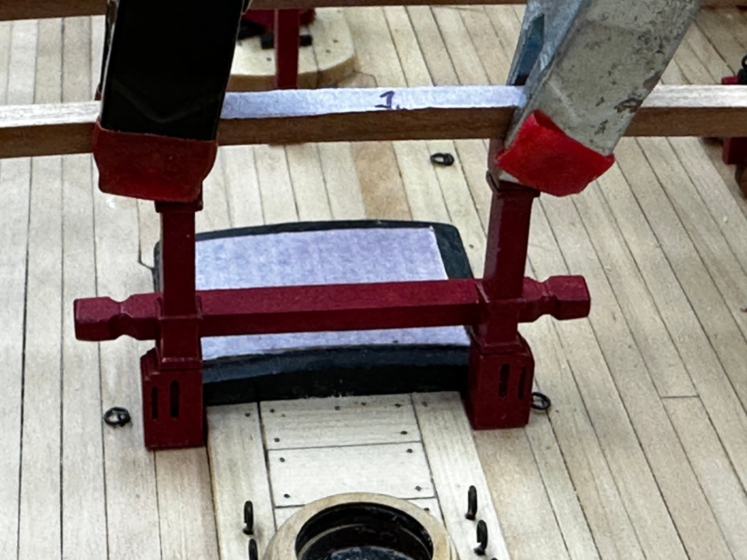
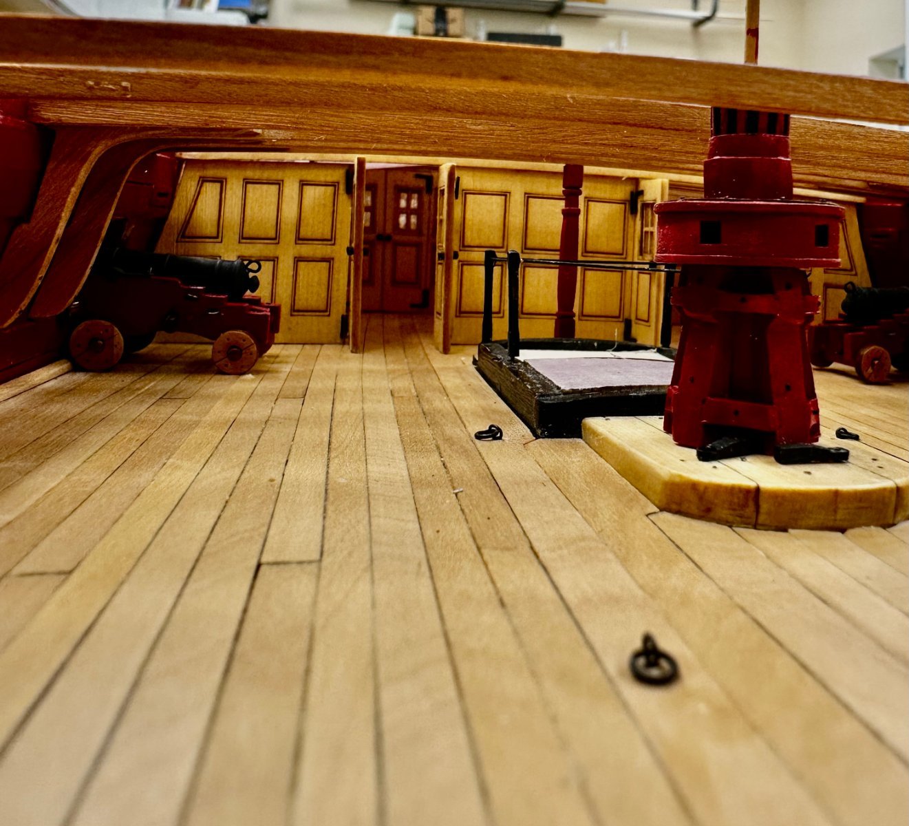
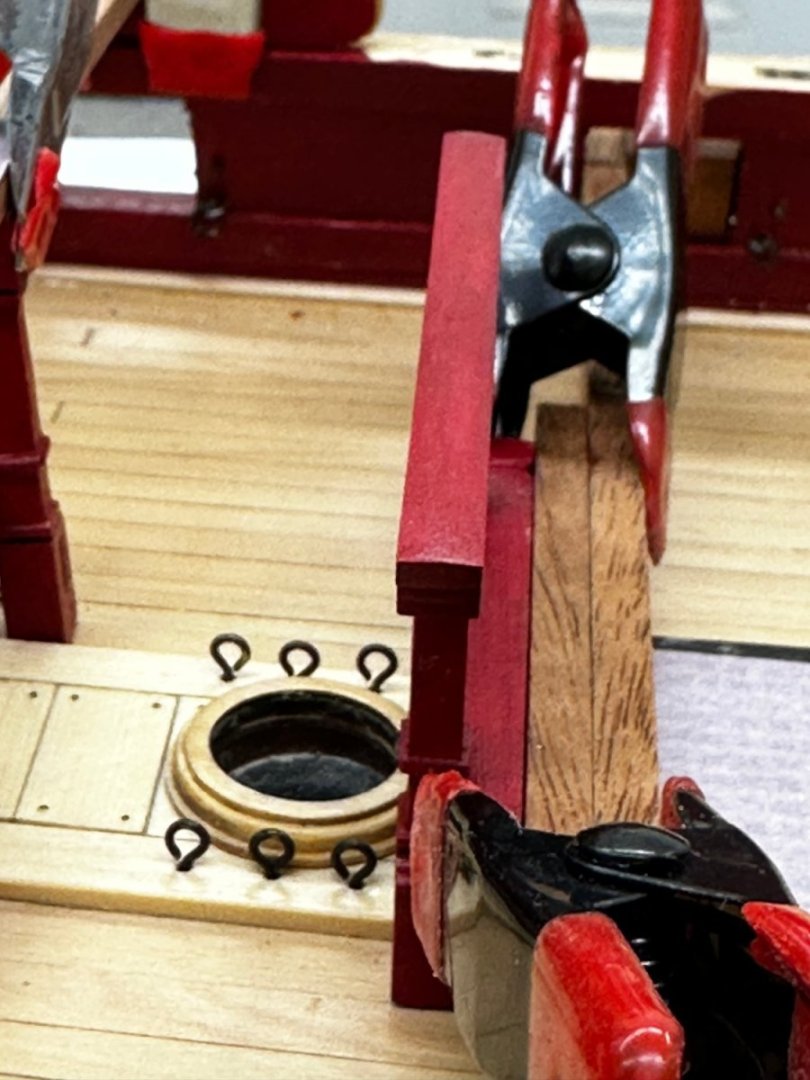
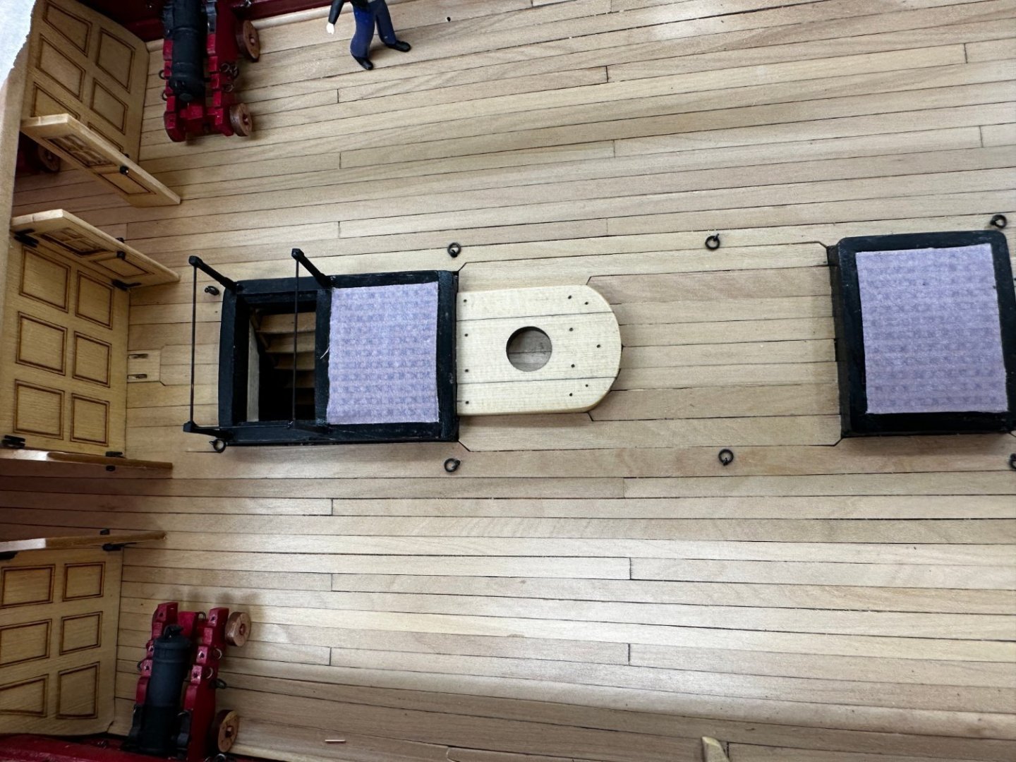
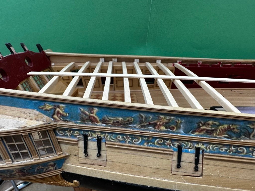
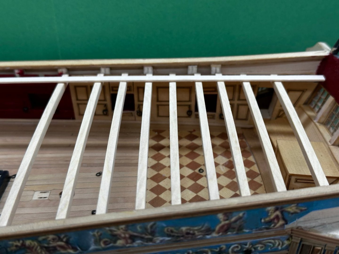
 After a dry run with the Rhodings for the Gallows and Jeer bits held in place with alligator clips I am confident (enough) in how things line up to permanently install the gallows. Speaking of Rhodings - I had about a 50% failure rate as they get pretty "tender" once the "hole" for the rod is in place and deep enough to allow easy rod passage. Anyway my first attempt at gluing the gallows in place was unsuccessful because I did such a good job finishing the deck that the glue would not stick. So I roughed up the deck a bit and then decided to peg the gallows. I used .039" music wire for the pegs (as I mentioned it is quite stiff). I used the Dremel to file a point on the end of each peg, CAed them into holes drilled in the legs and then used the points to mark where the holes had to go. Drilled the holes and decided to use medium CA to glue them in hoping that the CA would bond to the pegs as well as the deck. Now to try the "dry run again and locate the Rhodings for the jeer bits.
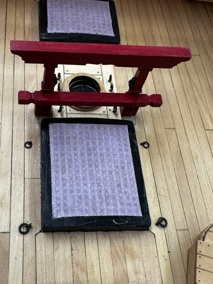
- 389 replies
-
- 3
-

-
- winchelsea
- Syren Ship Model Company
- (and 1 more)
-
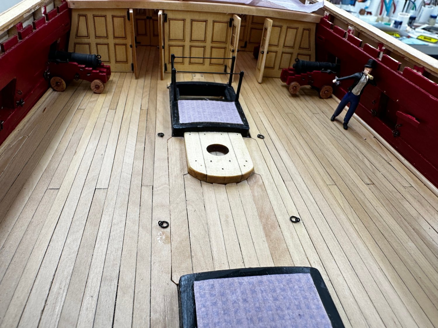
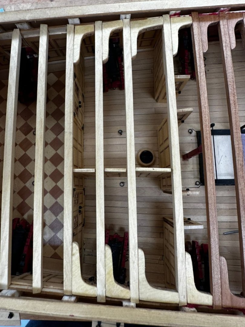
Now all but the last two (forward most) deck beams and knees have been installed. Note the clean appearance of the AYC knees in the aft cabin😀
- 389 replies
-
- 3
-
-
- winchelsea
- Syren Ship Model Company
- (and 1 more)
-
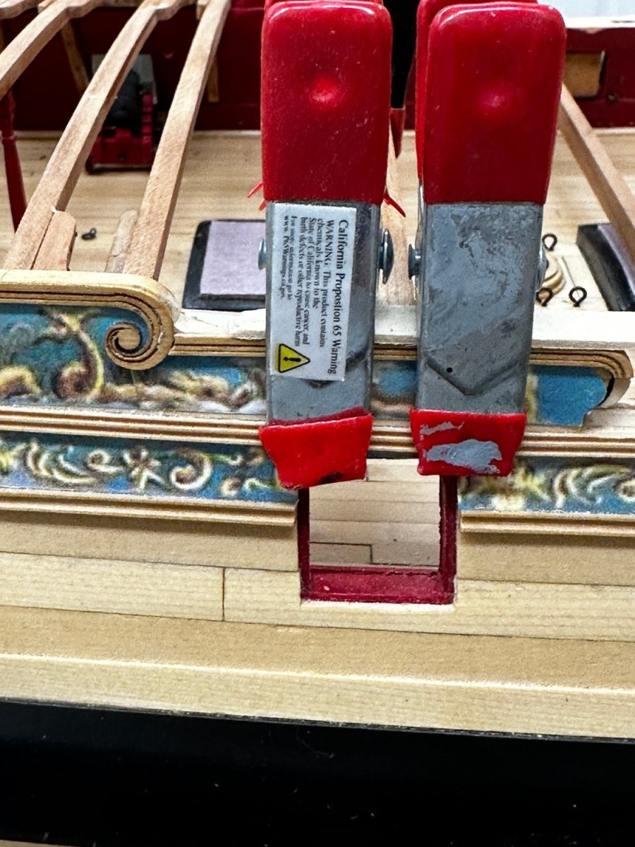
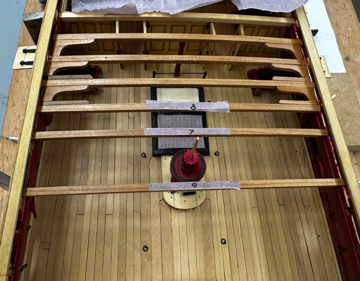
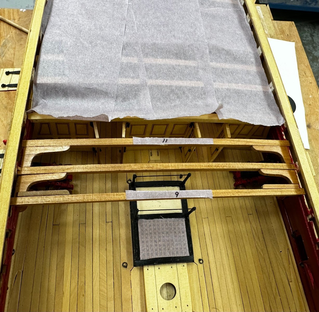
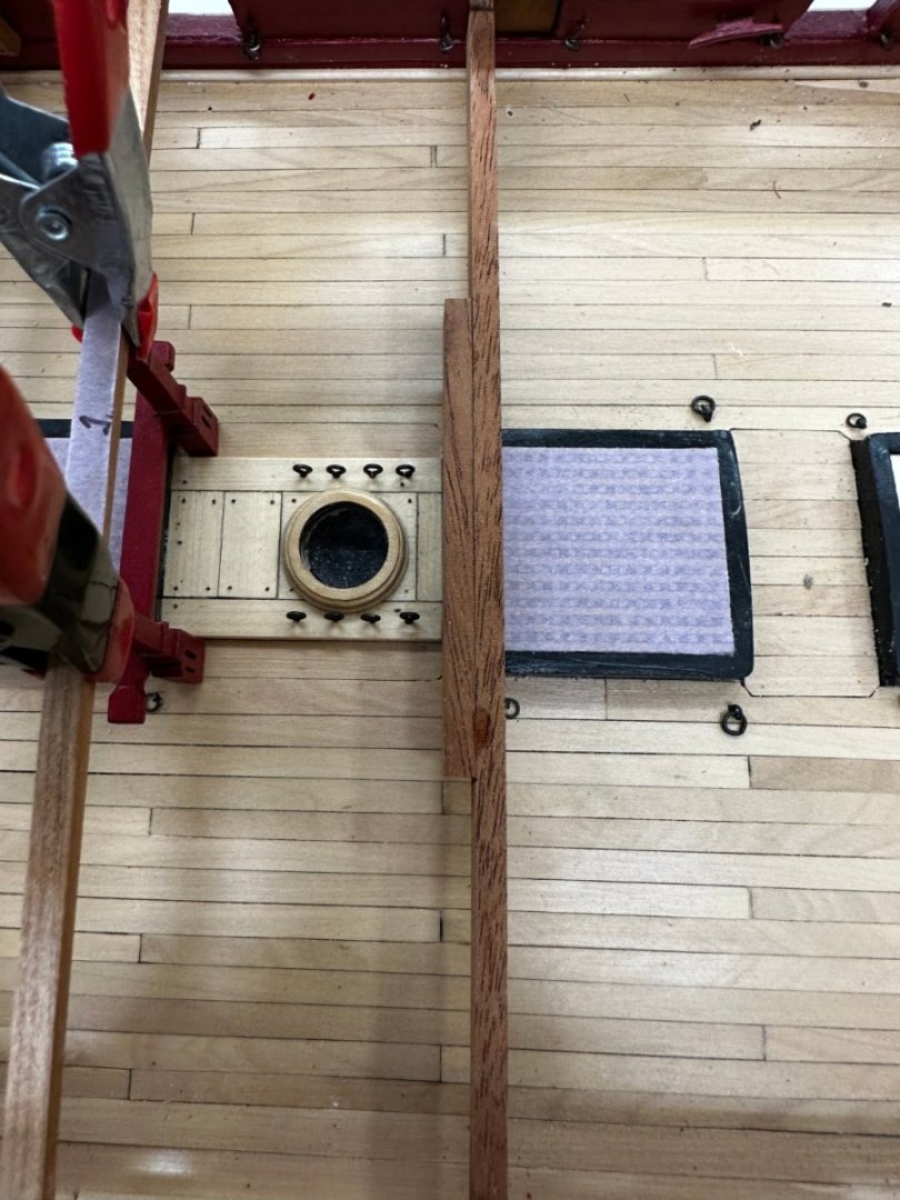
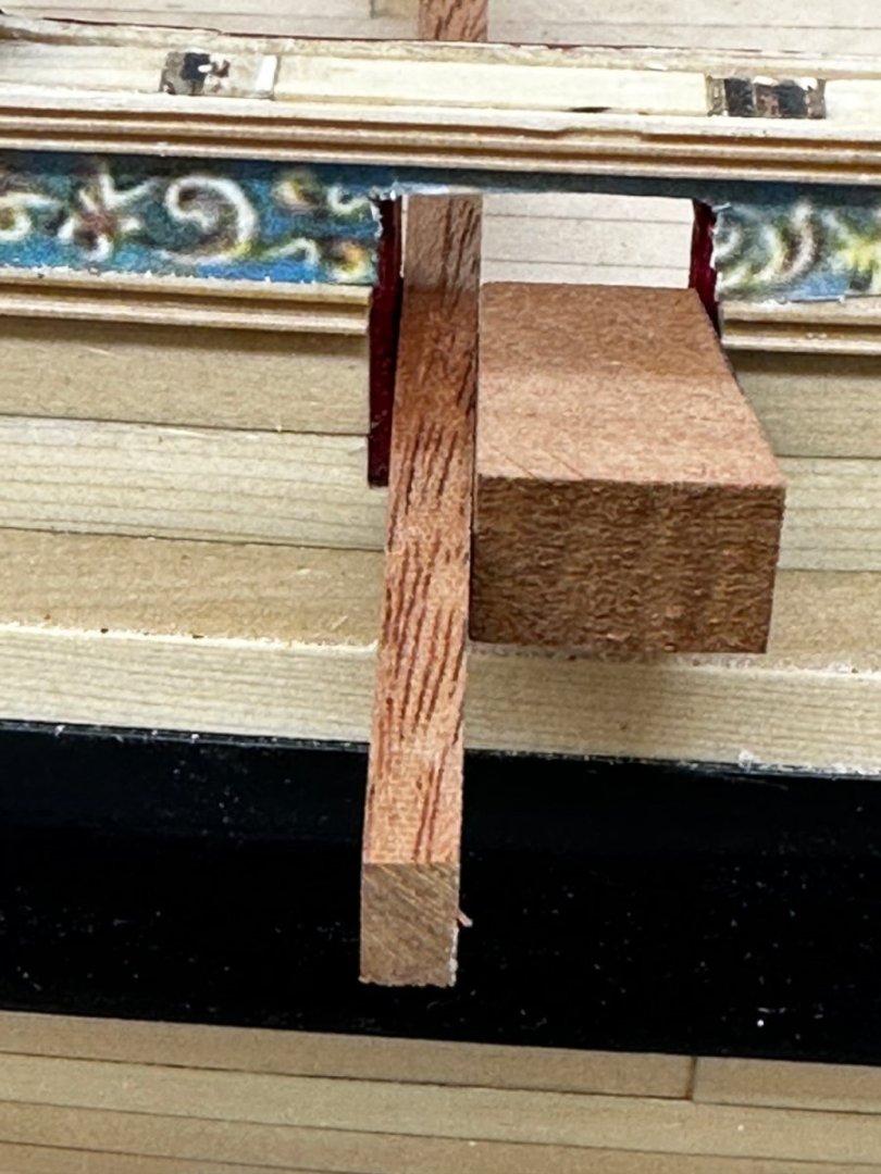
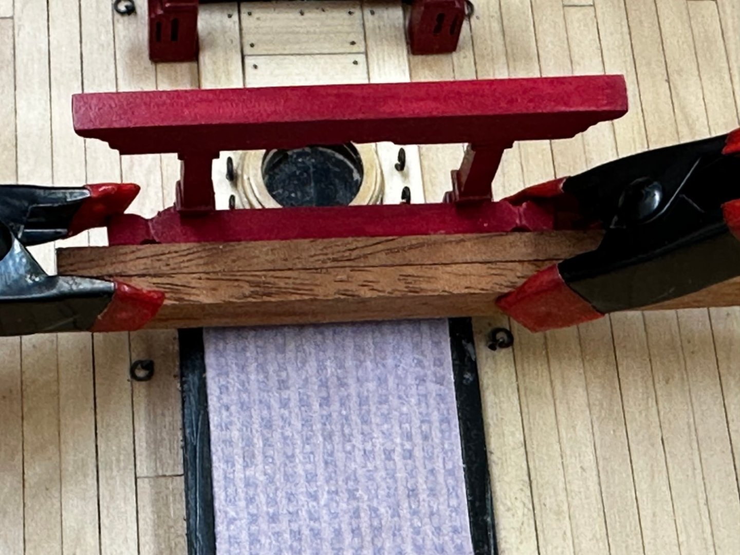
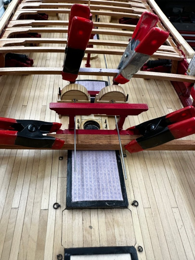
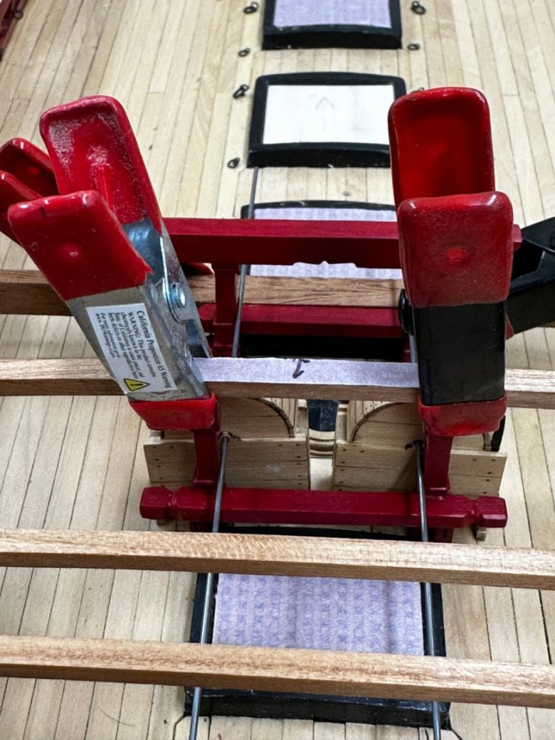
I built the chain pumps some time ago so with all but the last two deck beams in place it is time for the "Big Show" on installing the chain pumps jeer and gallows (and the two stanchions under the beam 3 (assuming the Breast Beam is number 1). I was searching for the "silver bullet that would get everything lined up without anything glued in place. The jeer bits are under the Breast Beam so first step is to secure the beast beam. I used two scrap pieces of deck plank (one on each side) to hold the beam down in the slot and two clamps to line the jeer bits up with the beam and keep them in contact. Now for the gallows. With no overhead beam to help locate the gallows I used a straight (hopefully) 1/8" X 3/8" beam across the deck at the aft edge of the #8 gun port. To keep the beam stable I used some wedges to secure the beam to the aft side of the gun port. I needed a spacer from this "beam" to get the gallows where the plans show them to be so I cut a piece of 1/8" X 3/8" material and glued it to the "beam". I chose the 3/8" beam so it will line up with the cross beam which is on the forward side of the gallows. Now for the chain pumps I used .039 piano wire for locating as it is very stiff (and I do not have any 1mm brass rod). The piano wire is too hard to cut to exact lengths so for the actual pump handles I will shift to .040 phosphor bronze (unless my order for 1mm brass rod comes in sooner than expected). So with the wire inserted through the chain pump, I located each pump so that the wire was against the jeer bitts and gallows up rights. This is a far as I have gotten - kinda feel like my dog that finally caught the rabbit and then couldn't figure out what to do next. I guess the next step would be to mark where the wires cross the uprights and make the Rhodings. I thought about using the black laser board (like the door hinges but thicker) for this but am not sure it would stand up to what may be several iterations of having rod of one kind or another inserted and removed.


- 389 replies
-
- 5
-
-
- winchelsea
- Syren Ship Model Company
- (and 1 more)
-
I surrender - I just needed something to obsess over while my spouse is in the "new house" mode.
- 389 replies
-
- 2
-
-
- winchelsea
- Syren Ship Model Company
- (and 1 more)
-
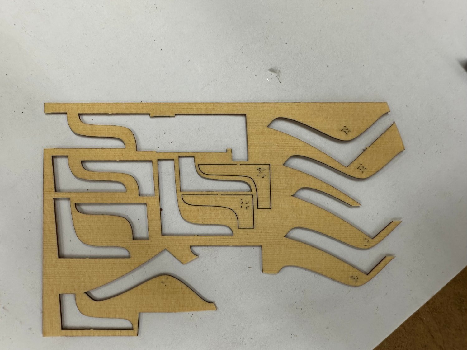
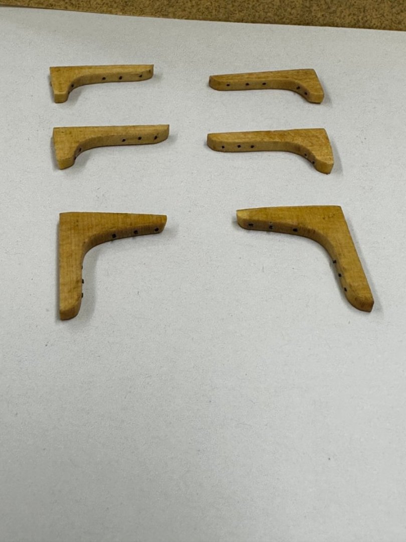
I finally fell upon a solution for the laser burn-thru. After I tried soaking one of the knees in bleach overnight. If anything the marking got worse. So after removing the knees that are required (I am using the first four AYC knees - the rest are cherry) I thickness sanded the carrier sheet to just under 1/32" thick. As you can see the burn thru is still present, even more distinct. But there are enough blank areas to allow the eight knees that I need to be glued to a piece of the thinned carrier sheet. Here is a #4 knee. I used the disc sander to get close to the knee dimensions and then sanding sticks and blocks to get the rest of the way is a Here is an almost finished #4 knee. You can see the extra layer needs a bit more trimming but you get the idea. WoP goes on after the sanding is finished. The jury is still out on whether I will try and thin the opposite side down to make the knee back to its original thickness but I will wait until I get ready to install to make that decision. Would probably have to be done manually. Small parts and a disc sander are not a "match made in heaven".


- 389 replies
-
- 2
-
-
- winchelsea
- Syren Ship Model Company
- (and 1 more)
-
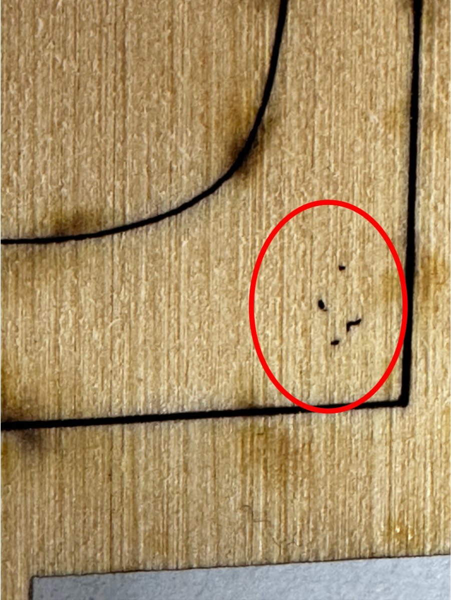
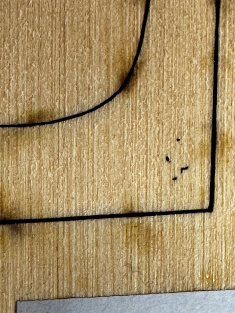
Glenn - in case it is not clear what burn thru I am talking about see below - and this is not the most worst example of this phenomenon on the carrier sheet I have. On some it only takes a little imagination to read the number (the mirror image of course).

- 389 replies
-
- 2
-
-
- winchelsea
- Syren Ship Model Company
- (and 1 more)
-
Glenn - the number has burned through from the other side on the interior of the knee not from around the edge as your example shows. I agree sanding off what you show is "no problem". Trust me sanding just makes the burned through area more obvious as more of the unburned material is removed.
- 389 replies
-
- 3
-
-
- winchelsea
- Syren Ship Model Company
- (and 1 more)
-
Another problem in search of a solution. The AYC knees supplied with the Chapter 7 package seem to have a problem with a "too hot laser". As you can see below the identifying number has burned through a bit from the other side. Unfortunately there does not seem to be a solution (other than they will all be covered by qdeck planking - assuming you follow the planking plans in the monograph). Since I am not following that planking plan I need to find a way to "cover-up" the burn through - sanding only makes it worse - don't as me how I know.

- 389 replies
-
- 1
-
-
- winchelsea
- Syren Ship Model Company
- (and 1 more)
-
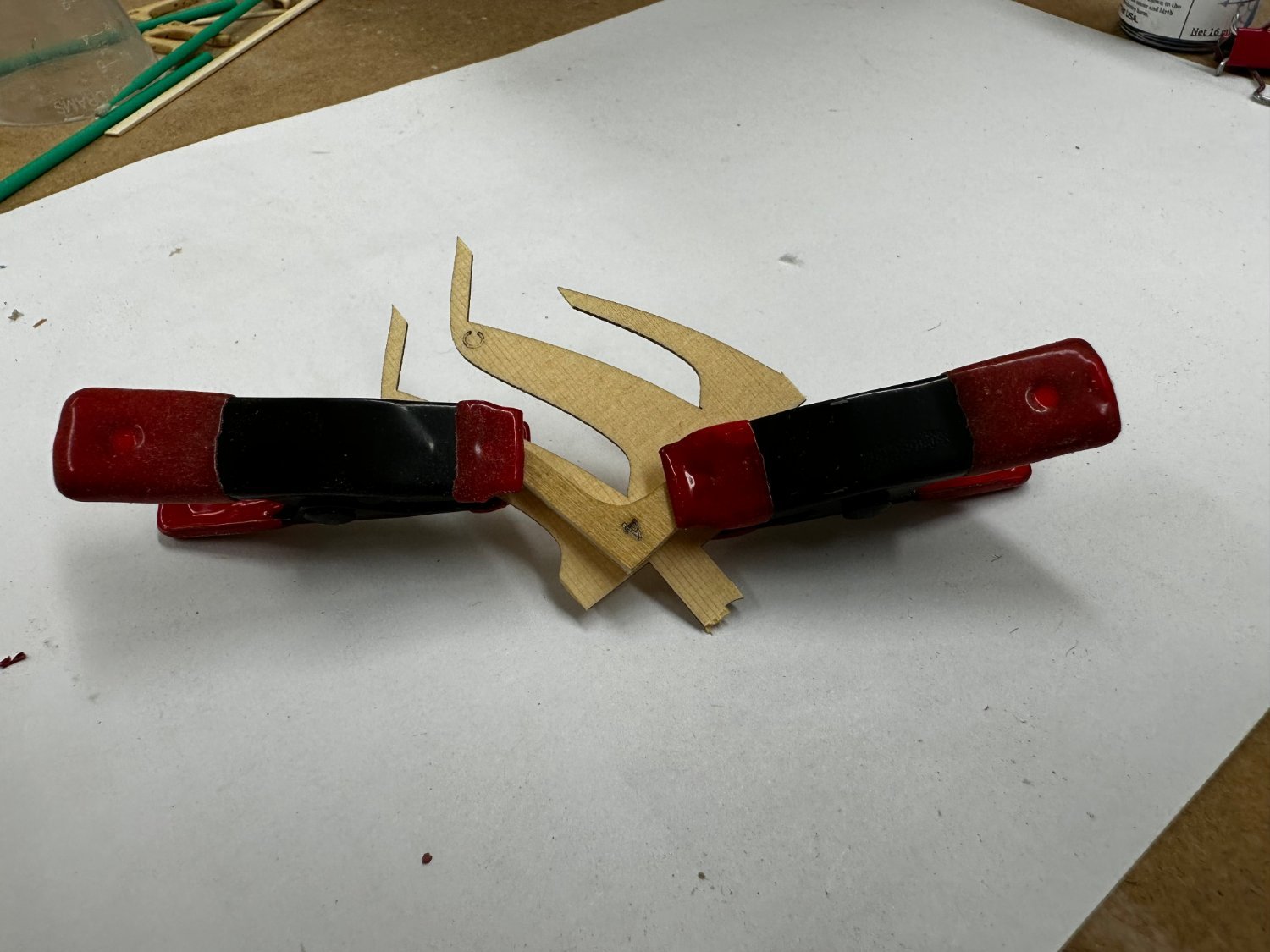
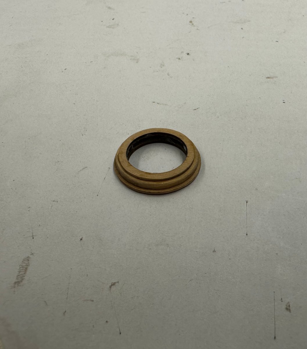
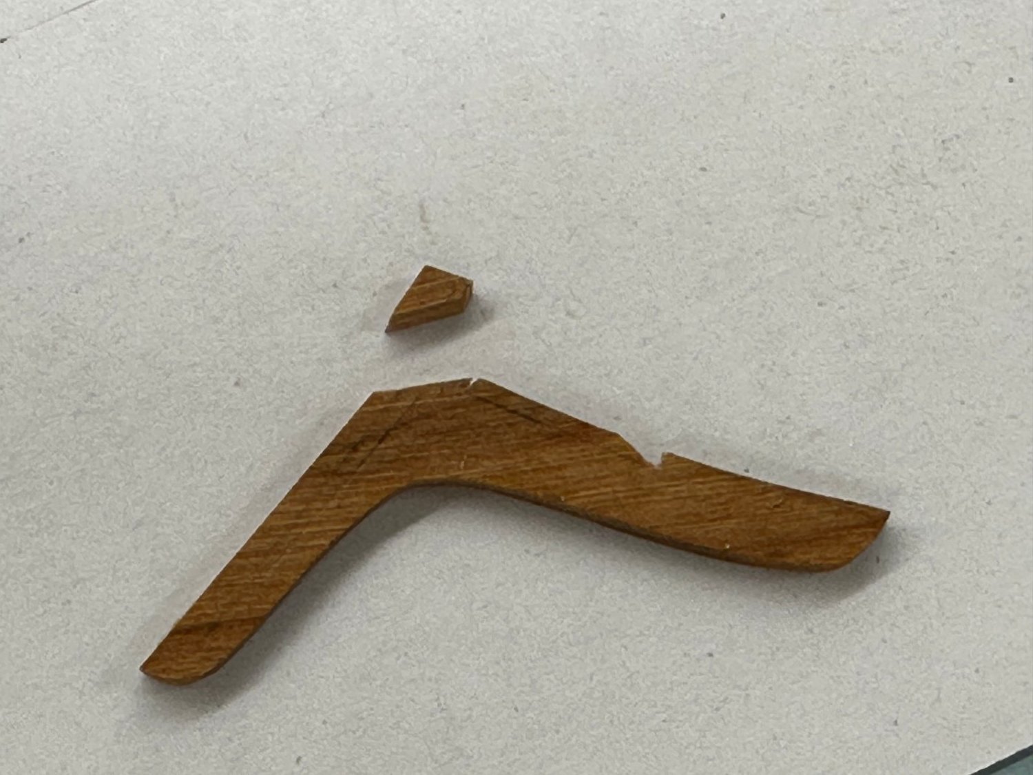
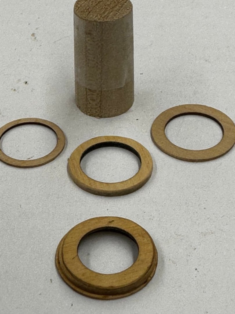
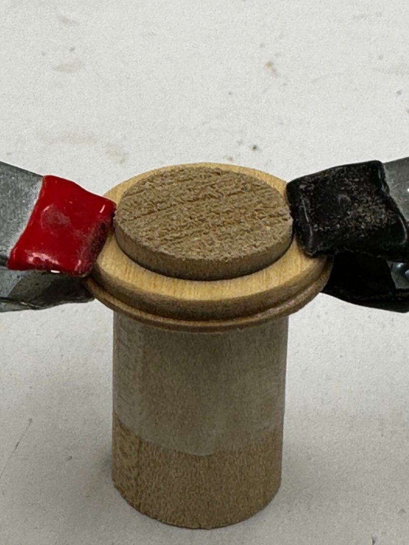
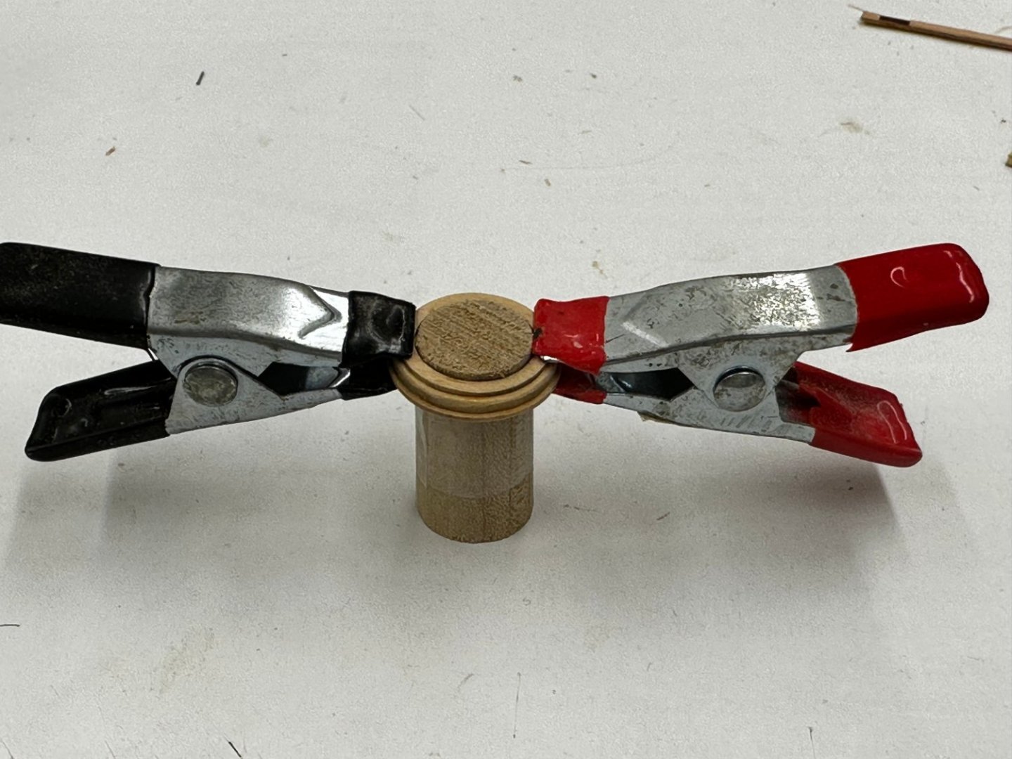
While we are reviewing "mistakes" I managed to mess up the main mast coat by failing to recognize that the layers had shifted when I applied the clamps to set the glue. With a new set of pieces in hand I decided to try and NOT replicate the mistake. I took advantage of the fact that all three layers have the same internal diameter. Thus if I could find a dowel the correct diameter I could stack the pieces one atop the other on the dowel and thus at least reduce the possibility that the pieces might shift out of alignment when clamped. Unfortunately I did not have a dowel of the correct diameter but 5/8" was just a bit too large. I used the disk sander and some sanding sticks to reduce the dowel to a bit less than the internal diameter of the pieces and then, to alleviate the possibility of gluing the coat to the dowel I wrapped the dowel with a single layer of Scotch Tape. And here is the old coat and the pieces of the new one along with the dowel "template".. I rounded the top edge of the middle layer and glued the first two layers together. And then the top layer. And here is my new main mast coat on its way to the hull - after a coat of WoP.

- 389 replies
-
- 2
-
-
- winchelsea
- Syren Ship Model Company
- (and 1 more)
-
A word of caution for those who may build the Winnie in the future. The knees for Chapter 7 come on a single carrier sheet (both lodging and hanging knees). And the knees are in various locations on the carrier to minimize the amount of wood required. This results in the some of the hanging knees having the grain running in a direction that is "sub-optimal" when trying to carve out the shape to fit the bulwarks and deck clamp. See below Note the direction of the grain in this piece. After this happened a second time (I am a slow learner) I adjusted my technique to make a very small mark at end of the required "slot" and cut a sanding stick just a bit smaller than the slot and used that to deepen the slot rather then run the risk of breaking off an even larger section.

- 389 replies
-
- 2
-
-
- winchelsea
- Syren Ship Model Company
- (and 1 more)
-
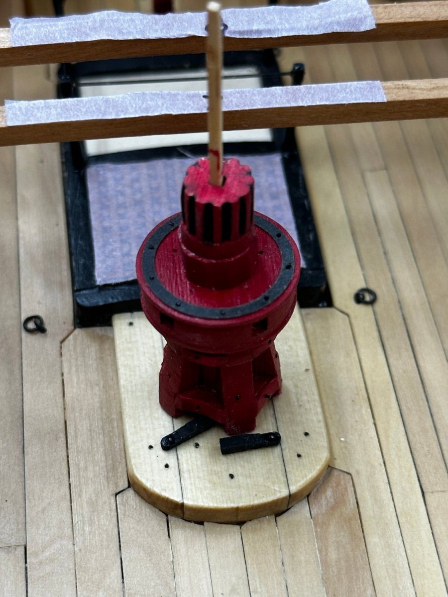
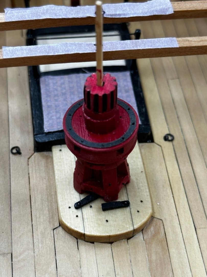
So I installed the lower capstan and fabbed, painted and installed the pawls. Speaking of the pawls, the only mention of them is in the instructions. The are not shown on any drawing that I can find including the capstan instructions from Syren. I did the best I could based on the one picture and a few words in the instructions. Having installed the lower capstan I am starting to have second thoughts about the upper being painted red. Which it is since I assembled the capstan what seems like a very long time ago. I have the cherry capstan kit and I think I will assemble the upper capstan a see how it looks without the red paint. I might also consider an unpainted AYC upper capstan. Anyway, working my way forward one beam/knee combination at a time.
- 389 replies
-
- 3
-
-
- winchelsea
- Syren Ship Model Company
- (and 1 more)
-
Proceeding down the deck toward the waist per instructions. Three lodging knees and two hanging knees done. I forgot the stanchion just forward of the paneled bulkhead so managed to get that added without undue difficulties. More cannon, deck beams and knees coming up...


- 389 replies
-
- 2
-
-
- winchelsea
- Syren Ship Model Company
- (and 1 more)
-
A minor milestone, the first lodging and hanging knees installed (correctly).

- 389 replies
-
- 2
-
-
- winchelsea
- Syren Ship Model Company
- (and 1 more)
-
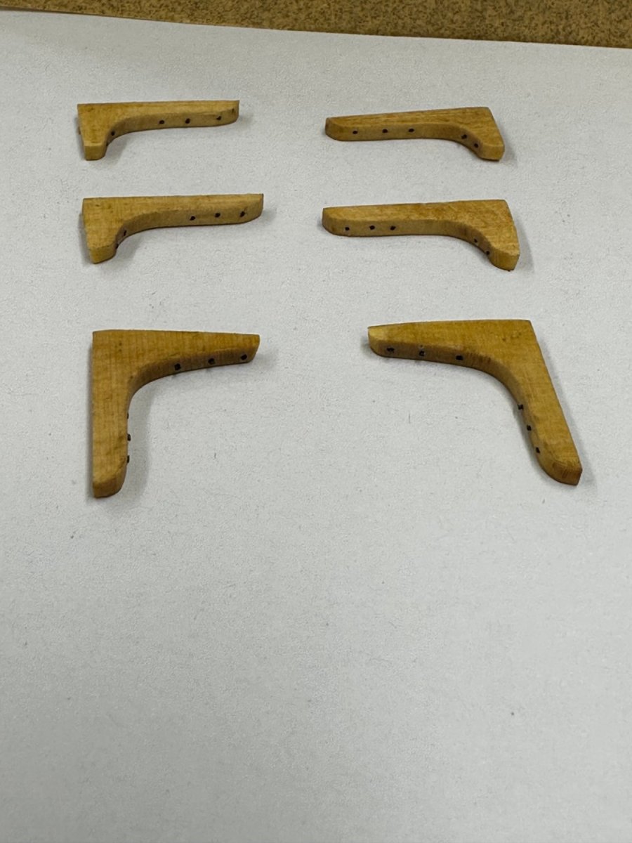
A solution to the "knee edge grain problem". Not elegant but workable, especially if I only have to worry about the ten hanging knees (i.e. only one side of the non-waist hanging knees). I took the knees carrier sheet and was able to rip three pieces from the non-cross grain side at about 3/64". I then sanded them down to 1/32. I then carefully (using the Byrnes disk sander) took 1/32" off the top of the hanging knee and glued an appropriate piece onto the top of the knee. Trim it up a bit, a coat of WoP and install. Here is what the port side looks like - significantly better than starboard IMHO.

- 389 replies
-
- 1
-
-
- winchelsea
- Syren Ship Model Company
- (and 1 more)
-
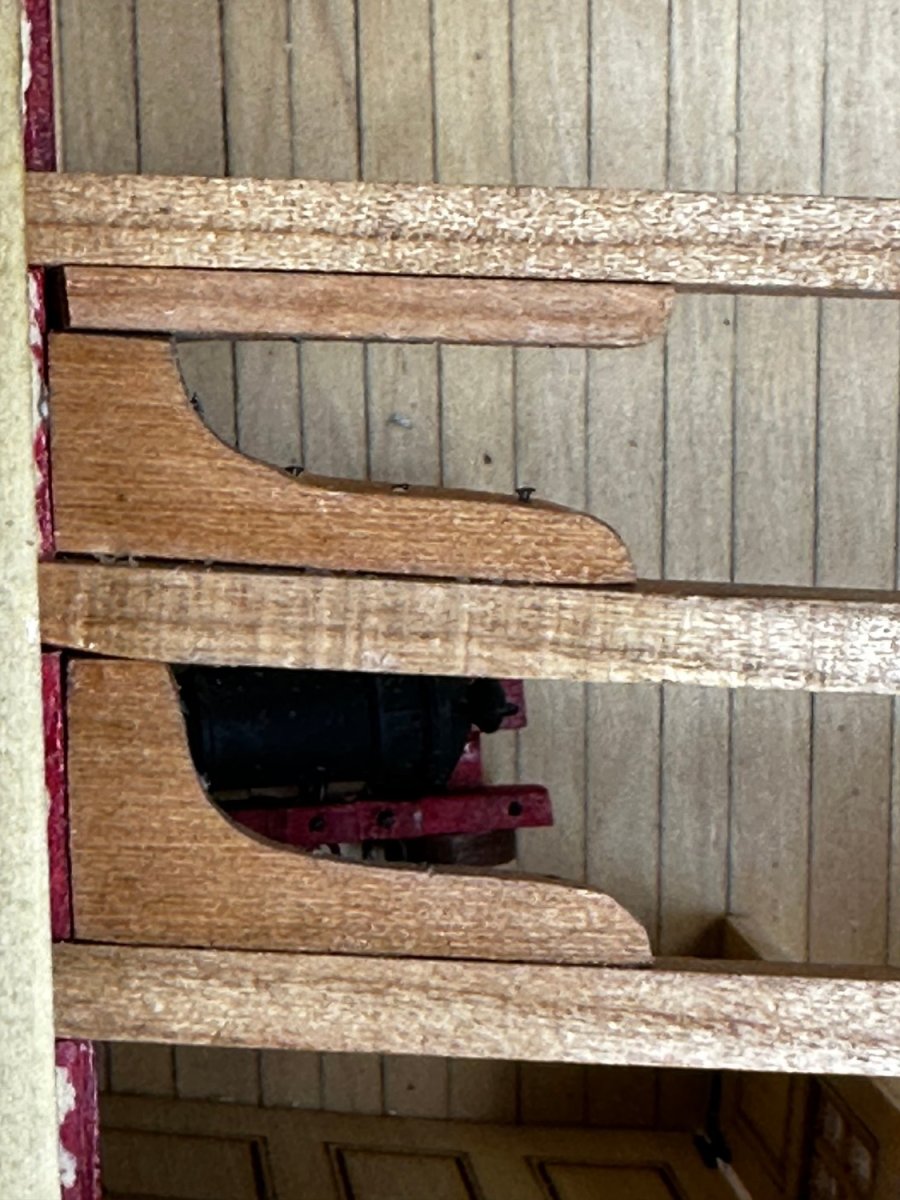
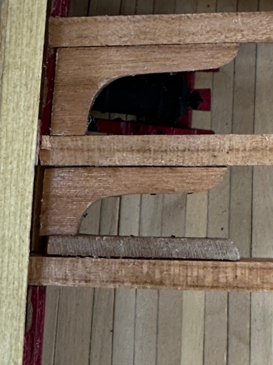
So I started to install the lodging and hanging knees forward of the paneled cabin. I need another set of the AYC knees since I mistakenly (obviously) installed the first set backwards - the long side facing forward - arrrrg. Anyway the lodging knees seem to be going great, they fit with very little adjustment. However, when I got to the first hanging knee I noticed a problem. The problem is the appearance of the lodging and hanging knees next to each other. On the lodging knee you are looking at the grain running athwartships while the hanging knee the grain is running fore/aft. Not really a big problem except it is very hard to get the two pieces to look the same. See picture below: That is the hanging knee behind deck beam 9 (by my numbering scheme) and lodging knee #6 (Chucks numbering) behind it (aft is up). You can clearly see the difference in the grain direction and appearance. And yes I added the bolts even though it will be hard/impossible to see them. Not sure what (if anything) I might do about this. I have satisfied myself that continued sanding is not going to change the grain direction so I am in search of another alternative. I have decided to plank one half of the q-deck (rather than that suggested in the monograph) so I only need to find a solution for one half of the deck - and that would be the port side since these are already glued in on the starboard side.

- 389 replies
-
- 1
-
-
- winchelsea
- Syren Ship Model Company
- (and 1 more)
-
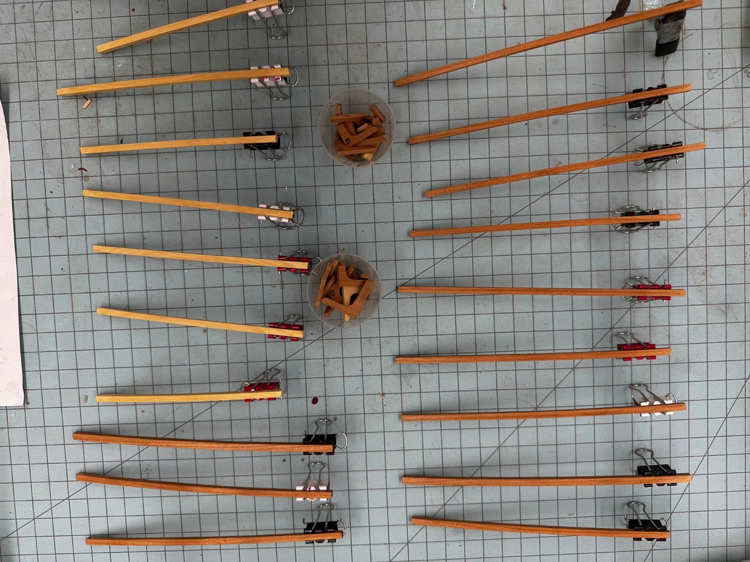
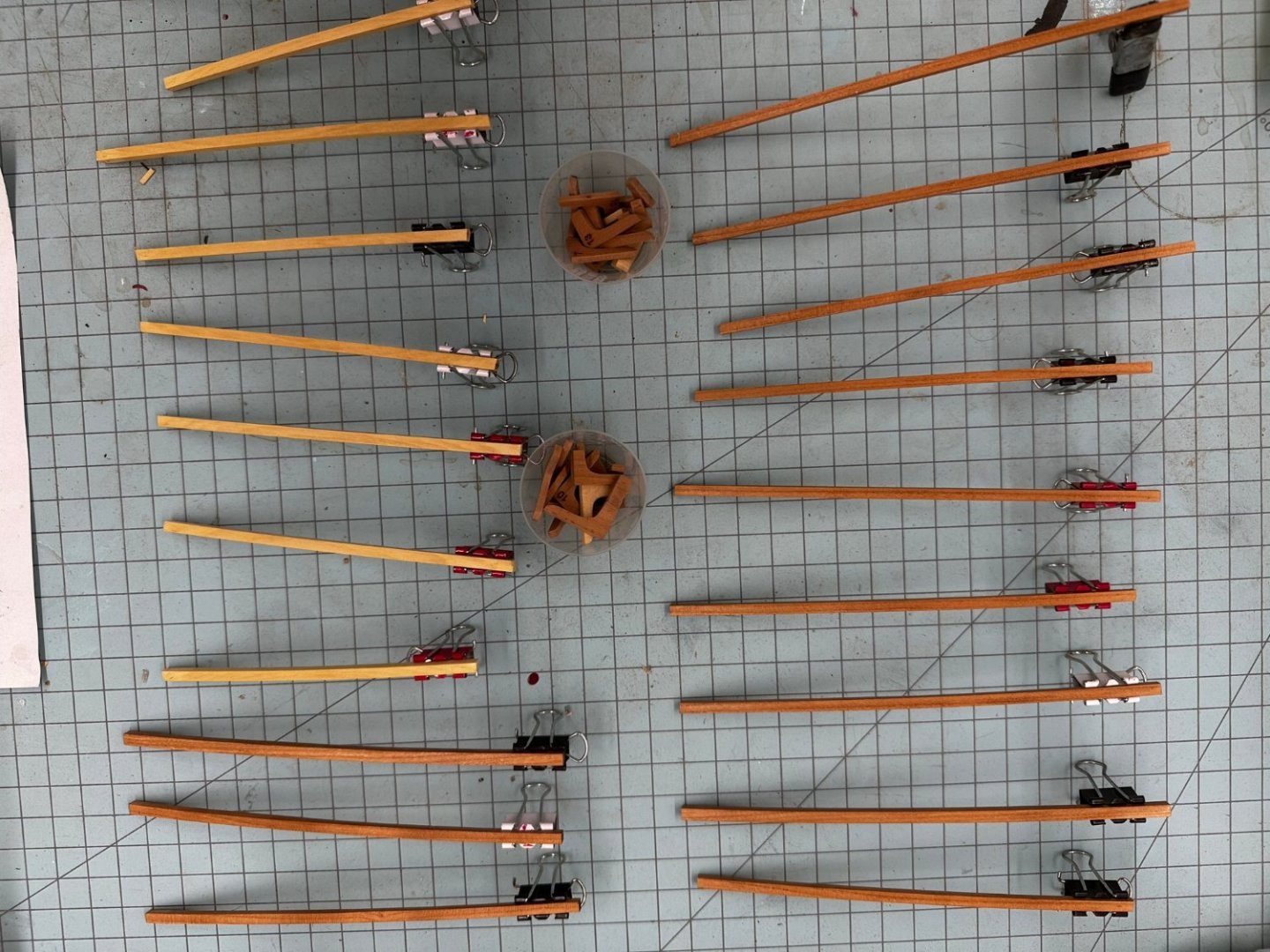
Moving forward the next item is the railing around the aft companionway. Per the monograph I used 1/16" X 1/16" boxwood to fashion the posts using the "poor man's lathe" a Dremel tool. It was surprisingly easy to make one post. The challenge is making four that are identical enough to keep the railing horizontal. I decided to make eight to start and then pick the four that were the closest to the same. I pegged them to the coaming with .025" piano wire and thin CA. I like piano wire because it is very stiff if somewhat difficult to cut in short lengths. For the railing I used .025 phosphor-bronze wire (painted black after installation) secured with thin CA. All in all it went more or less smoothly.

- 389 replies
-
- 4
-
-
- winchelsea
- Syren Ship Model Company
- (and 1 more)
-
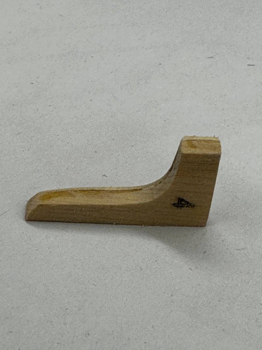
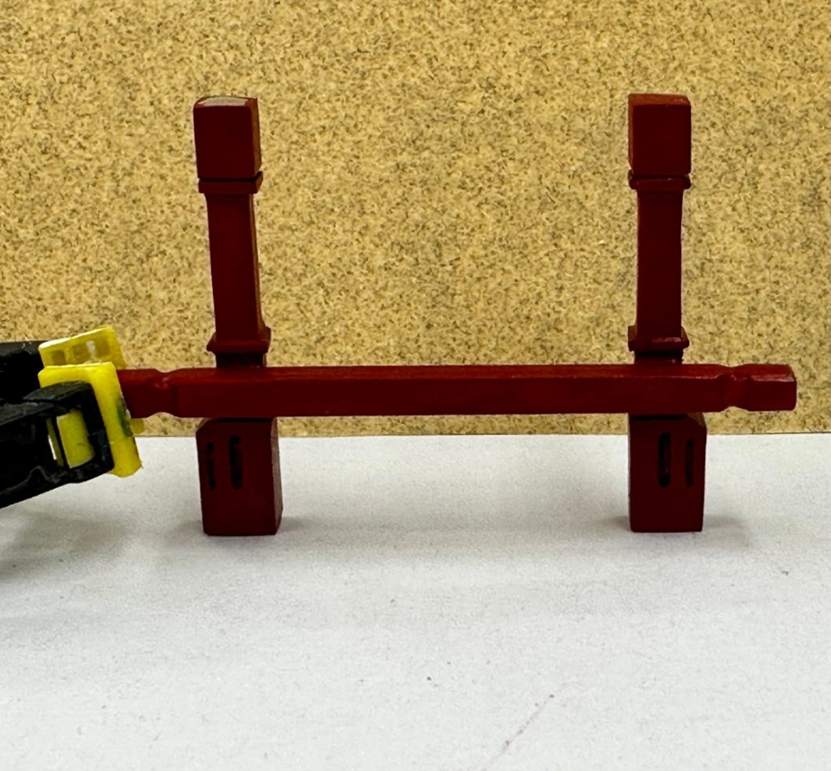
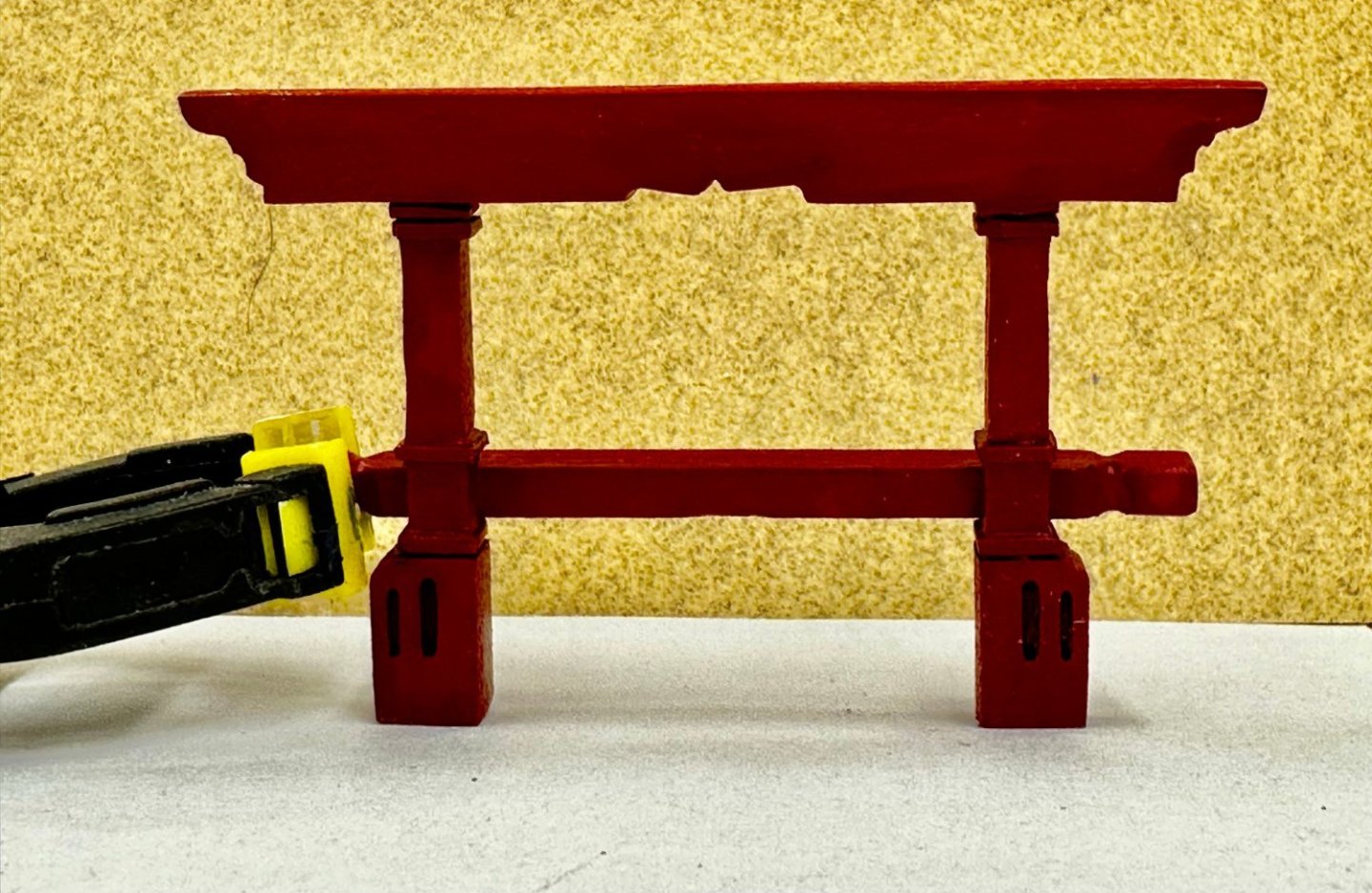
I am ready to stick a fork in the paneled section of the gun deck and call it "done". Since there are no knees in the Great Cabin I have left the deck beams and cannon there unglued and covered to reduce the amount of "stuff" that will find its way in there and have to be cleaned up later. The section forward does have lodging knees (but no hanging knees) so the deck beams have to be glued in and then the knees installed. That was the last step once all the "stuff" (mizzen mast coat, the cabin divider and the two cannon) was installed. I will get the knees in the paneled section later - as I am doing them in the aft part of the next section. Do not want to start that "process" with only three sets to install. While waiting for glue to dry and for an occasional break I also built the main and jeer bits. Nothing really difficult here - installation with the pumps looks to be a different matter.


- 389 replies
-
- 2
-
-
- winchelsea
- Syren Ship Model Company
- (and 1 more)
-
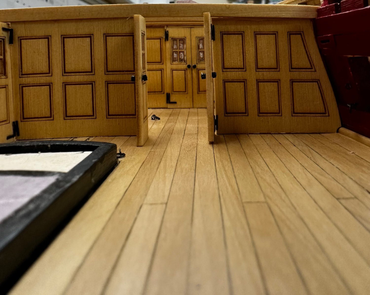
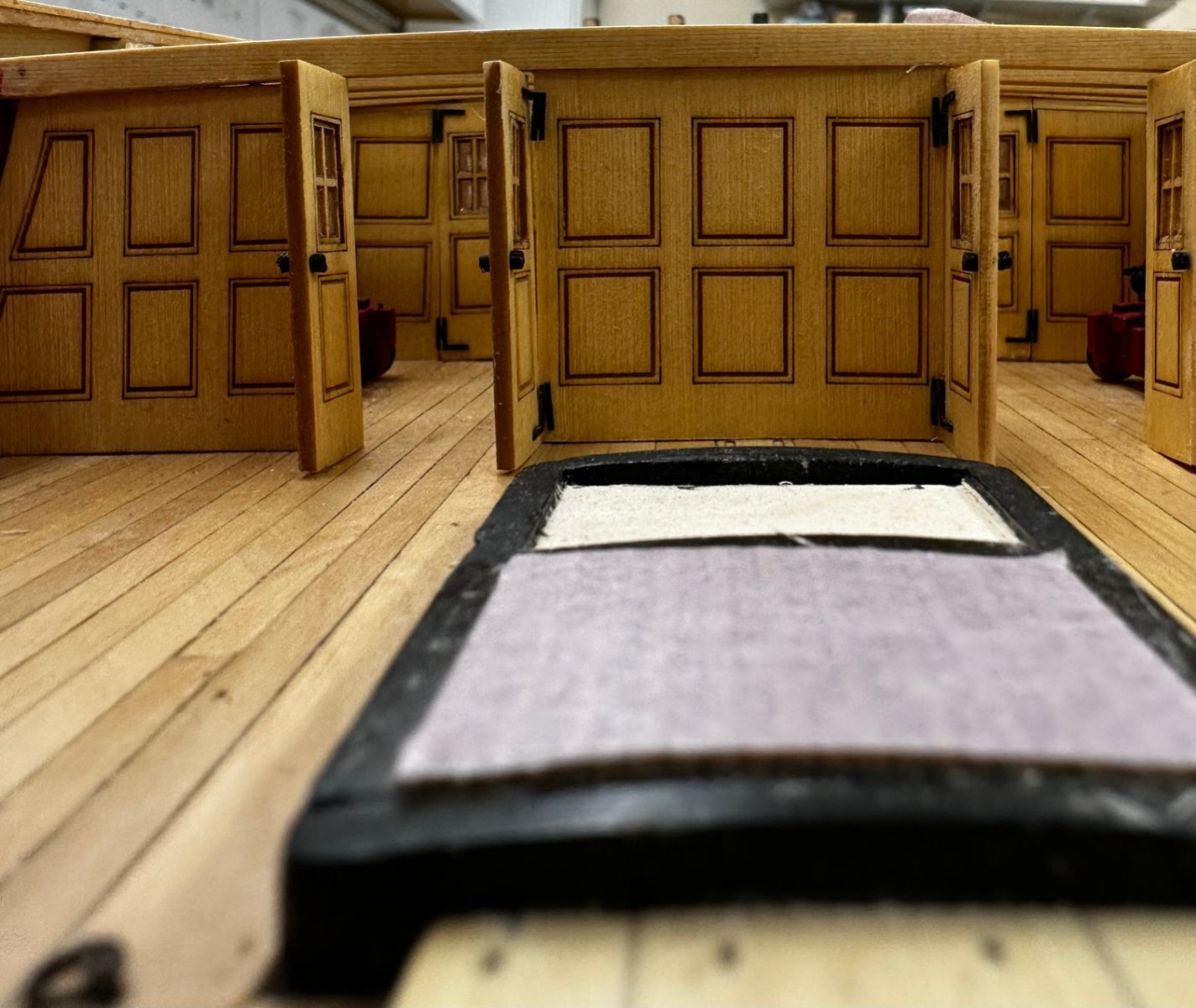
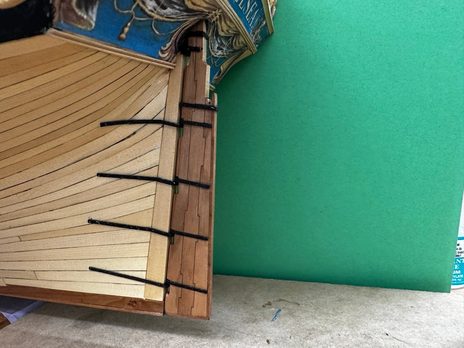
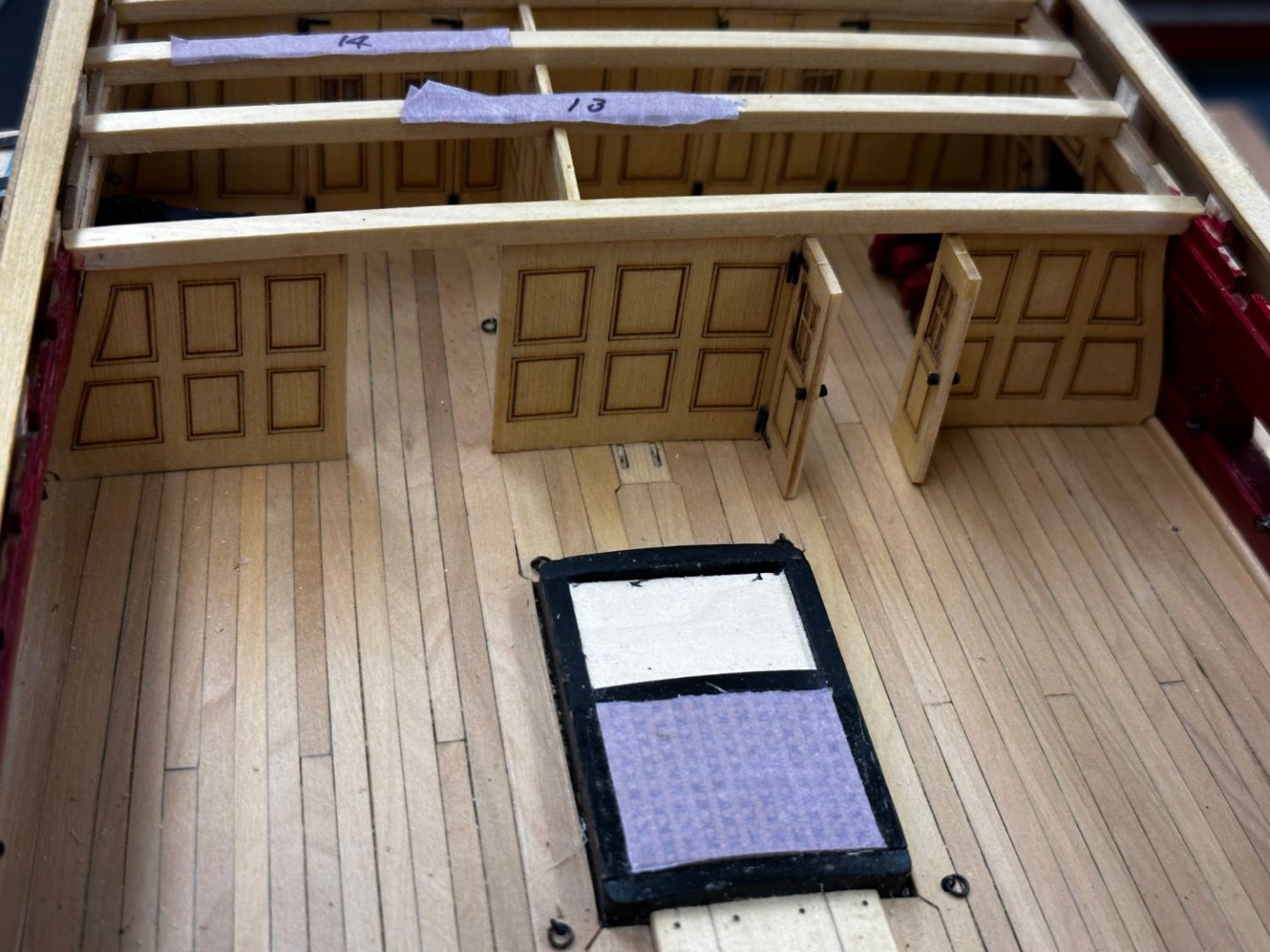
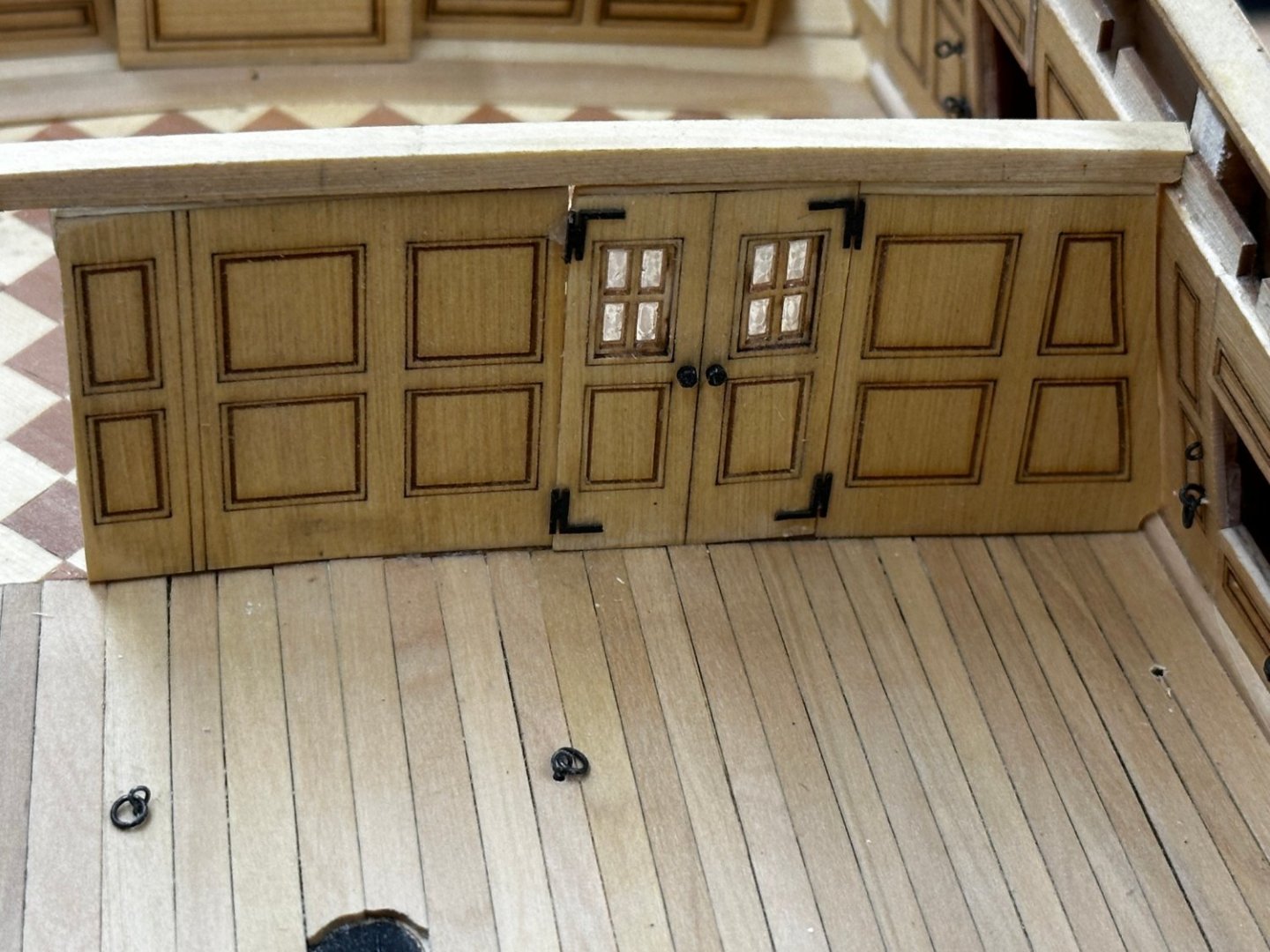
As threatened I decided to leave the doors on the forward bulkhead open. As it turns out the laser board hinges are pretty strong. The doors are still glued to the deck but they hung there by the hinges until the glue set. I measured and would have to remove a bit less than a total of 1/8" from the doors and starboard side bulkhead to get the doors to fit closed. So the other pair will be open also. Here is the forward bulkhead with one set of doors completed. And since there will be knees between the deck beams over this section I fitted them and added the simulated bolt heads. I used .40mm fishing line for these bolt heads. All the previous bolt heads on the cannon carriages, rudder, etc. used .52mm fishing line. Both are supposedly 20lb test line. I used the smaller line because I suspect the bolts used in the knees were probably somewhat smaller than those used in the larger items (and I am running out of the .52mm stuff). Depending on how the quarterdeck is planked the knees and especially the bolt heads could be invisible. When I built Confederacy I planked just one side a bit past the centerline to give all the centerline equipment a solid resting place. That exposed the knees on the other side. may do the same on Winnie. Herre are the AYC knees shaped, Polyied and "bolted".
- 389 replies
-
- 5
-
-
- winchelsea
- Syren Ship Model Company
- (and 1 more)
-
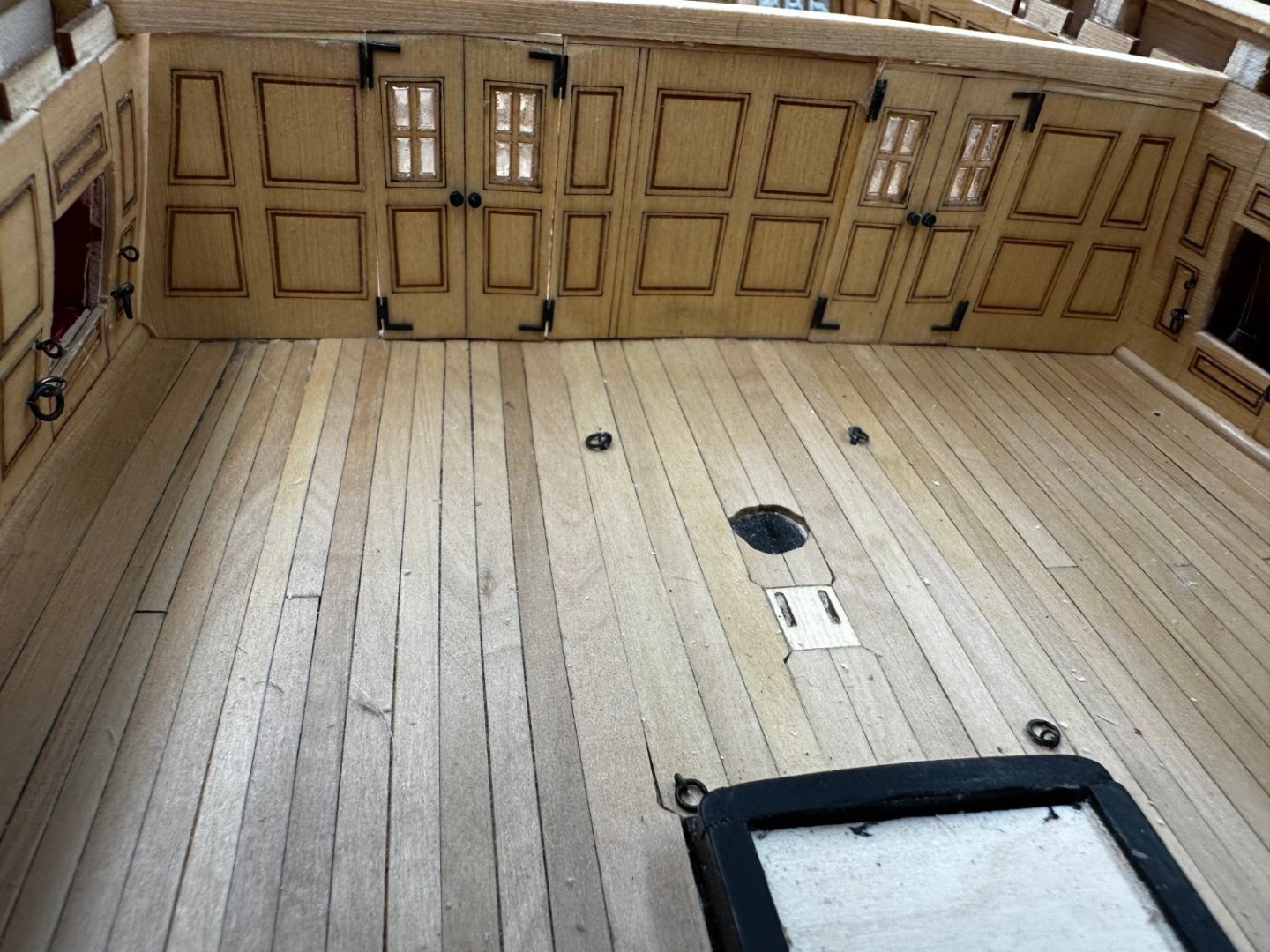
Aft bulkhead installation completed. looking for a way to reduce/eliminate the light comes through from the great cabin. It will. not be so obvious with some portion of the q-deck planked over but... To avoid issues with pieces being too wide (if in fact that comes to pass on the next (and final) bulkhead) and not getting the seams as "seamless" as one might like, I may resort to leaving one door of each pair (or maybe both) open rather than closed. I could argue that it would give a better view of the guns in these spaces or ...
- 389 replies
-
- 5
-
-
- winchelsea
- Syren Ship Model Company
- (and 1 more)
-
I have 2/3rds of the "Great Cabin" bulkhead installed. I used the "Window Maker" rather than the acetate sheets as I have done throughout. I had the opposite problem to what is described in the monograph - the bulkhead pieces were not tall enough, rather than too tall. I had to add a 1/32" filler piece on the top of all three pieces and then sand it down to a "snug" fit. In addition to not being tall enough the provided pieces had to be narrowed considerably to fit across. I guess I did not do a good enough job thinning the inner bulwarks. I also glued the two doors together and added them as a unit. I probably should have do them separately so I could thin both sides of each door - a lesson for the next (and final) bulkhead.
- 389 replies
-
- 6
-
-
- winchelsea
- Syren Ship Model Company
- (and 1 more)
-
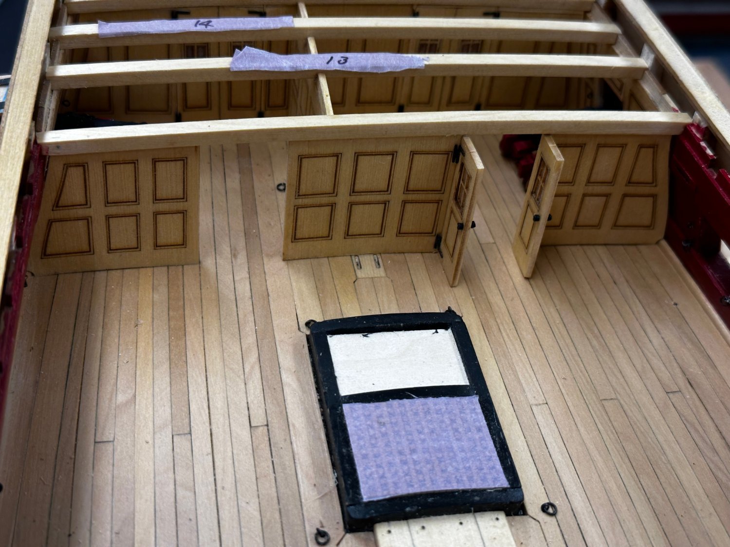
All the aft deck beams have been cut and fitted and I got all the lodging knees off the carrier and the laser char cleaned off - between the deck beams and the knees it seems all I have done for two days was sand off laser char. But that is considerably faster than having to fab the deck beams/knees from a drawing. As I mentioned above I am using the AYC beams in the paneled area and the cherry beams elsewhere. I also decided to forego the red bottom and sides of the beams. I know that is the contemporary model "motif" but I think it sort of takes away from all the other neat details on the model. Maybe too much of a good thing IMHO. So here are the aft beams with a second coat of WoP on the tops and a single coat of the sides/bottom. I probably will have to sand some of this off when it comes time to add the knees but that is a ways in the future.
- 389 replies
-
- 5
-
-
- winchelsea
- Syren Ship Model Company
- (and 1 more)
-
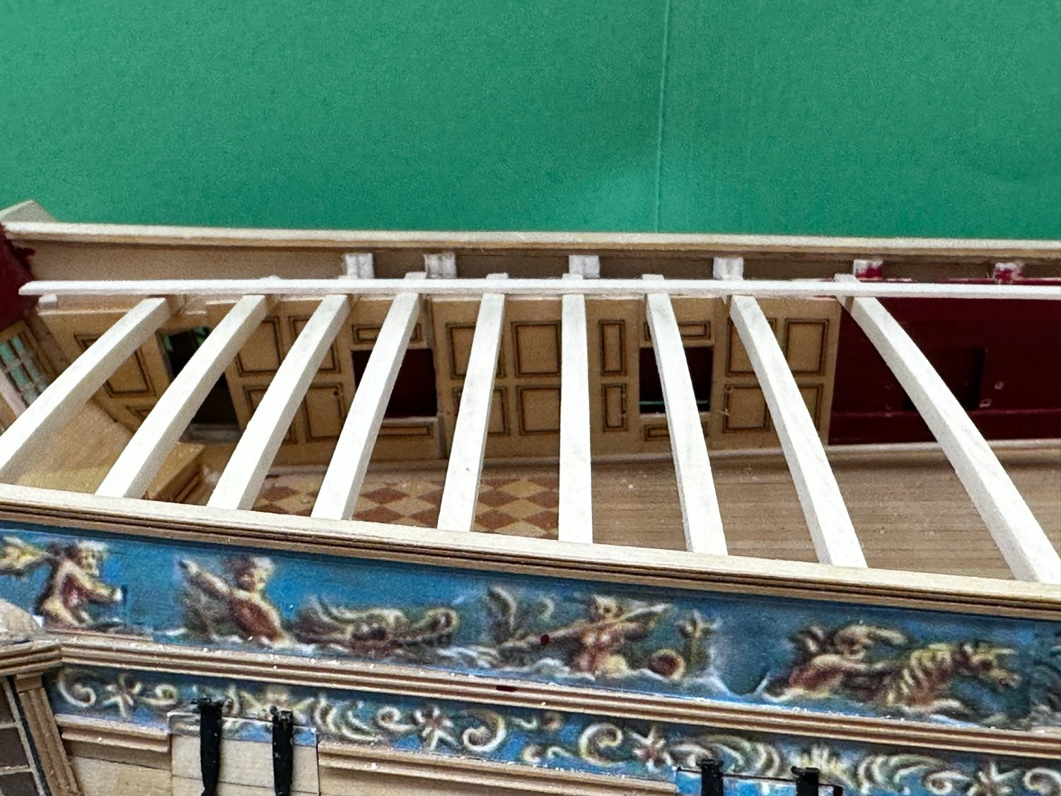
After what seemed like forever sanding laser char off the deck beams I started to "fitting" process. I am going to use a combination of Cherry and AYC beams. AYC in the cabin area and Cherry elsewhere. I have the AYC beams cleaned up and cut for the cabin area. Before going any further I thought it wise to see if there were any issues with a beam too high or low. So I took a 3/64" X 1/4" batten about 9" long and laid it across the deck beams in the center and on each side. No obvious problems as far as this test goes. I will run this again when I get the stern most beam in place. I soaked the two pieces of the stern-most deck beam in hot water for 20 minutes than clamped it to one of the AYC deck beams to try and get the correct camber. That seemed more likely to yield accurate results than the instructions

- 389 replies
-
- 4
-
-
- winchelsea
- Syren Ship Model Company
- (and 1 more)
-
Cherry rudder fabbed and installed. It was considerably easier the second time building the rudder. I think it looks better than with the cedar one but then...

- 389 replies
-
- 4
-
-
- winchelsea
- Syren Ship Model Company
- (and 1 more)
-
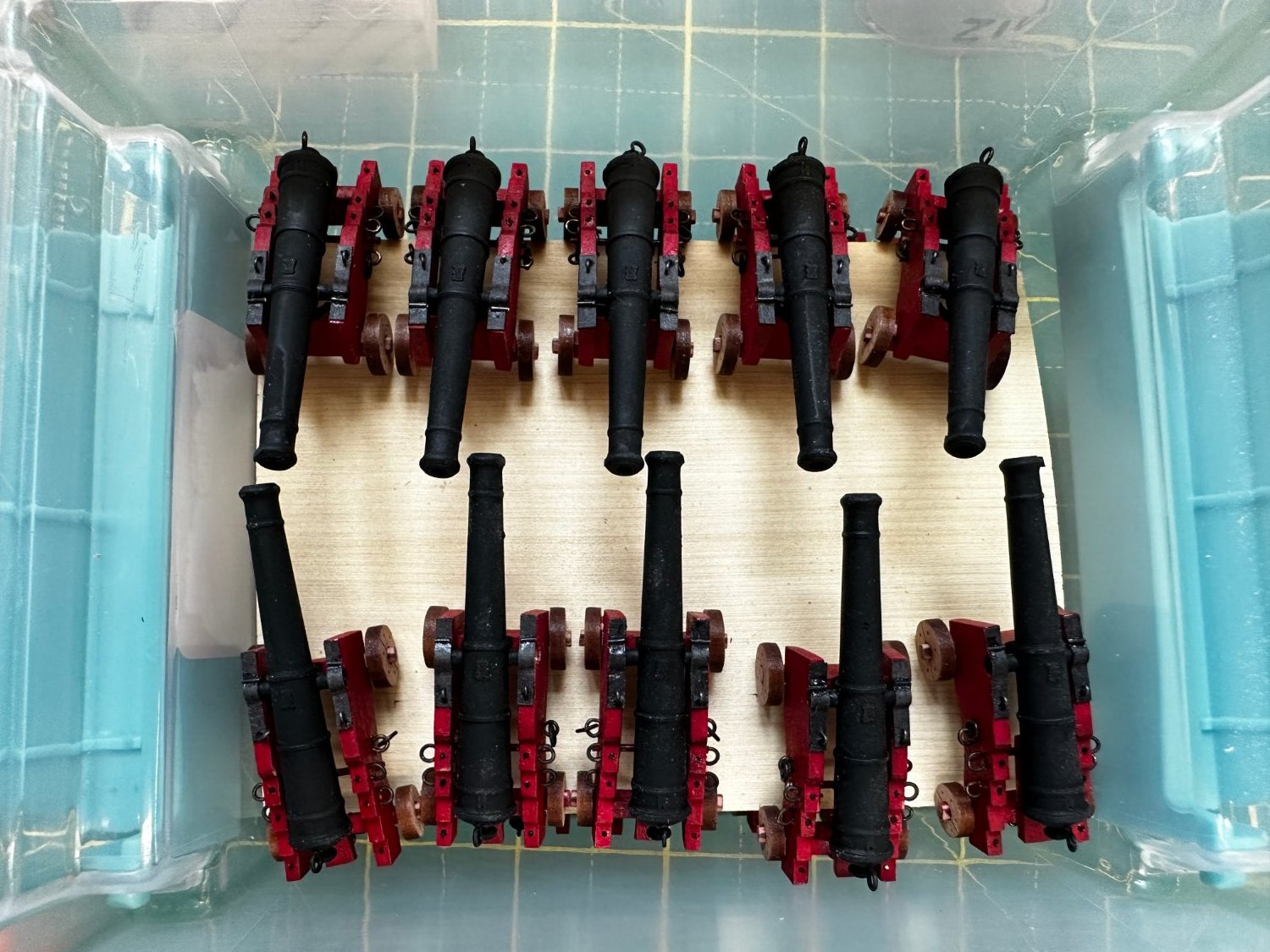
The second twenty completed. I have to stop here as I am out of the Vanguard cannon (I thought I had enough but I guess I flunked counting In kindergarten). It will be "quite a while" before I need more than 20 cannon. At the moment I am building the chain pumps before starting on the deck beams. That promises to be much "fun".

- 389 replies
-
- 5
-
-
- winchelsea
- Syren Ship Model Company
- (and 1 more)
-
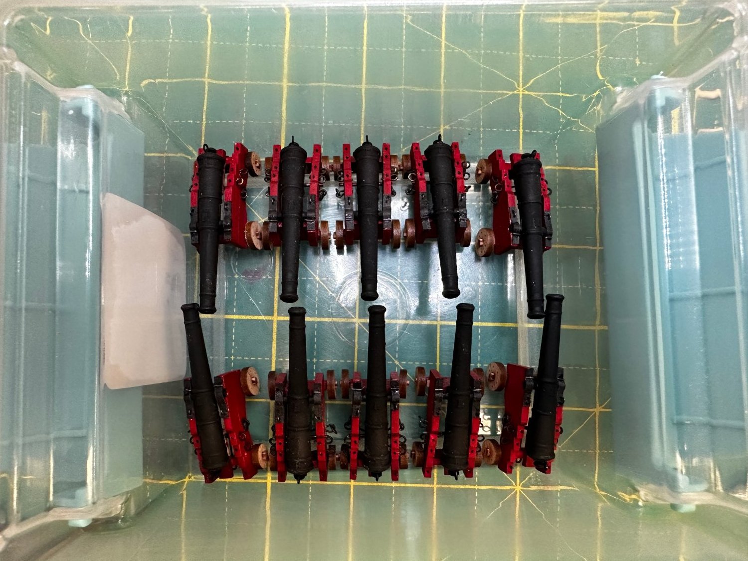
The first ten cannon/carriages in storage container. I read through all of Chapter 7 and it will be awhile before any of these are needed for permanent installation. And all will need one last pass with the red and black paint and some WoP on the wheels. No matter how many times I have touched up the paint/blackening so far I am always finding places where the red is missing or the blackened brass ain't so black anymore.

- 389 replies
-
- 3
-
-
- winchelsea
- Syren Ship Model Company
- (and 1 more)