HOLIDAY DONATION DRIVE - SUPPORT MSW - DO YOUR PART TO KEEP THIS GREAT FORUM GOING! (Only 72 donations so far out of 49,000 members - Can we at least get 100? C'mon guys!)
×


cdrusn89
-
Posts
1,915 -
Joined
-
Last visited
Content Type
Profiles
Forums
Gallery
Events
Everything posted by cdrusn89
-
 The down side of using the 3/16" wide planks is that it requires many more scarf joints than using the 1/4" but.... So, at least according to the plans, I have arrived at the point where the remaining rows need scarf joints - at least at the bow. The plans do not show any at the stern. Also unfortunately, the starting point for the forward planks is now 1/4" wide planks to accommodate the scarf joint. The first one needs to come to a point so I carefully cut the "slot" for the point trying to keep the approx .1250" width of the planks at the bow and then tapered the plank back to the 3/16" width at the end. Here it is prior to installation. I am going to complete this (the 8th) row before I tackle the next row where the first piece needs to be both curved and straight at the bow.
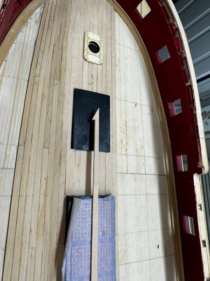
- 389 replies
-
- 3
-

-
- winchelsea
- Syren Ship Model Company
- (and 1 more)
-
Thanks Glenn - the medium CA is working better than the thin. I abandoned the hide glue as it is not nearly as brown in use as the packaging led me to believe. At any rate five rows done on the port side and things seem, although I am never really sure how well until the sanding is done, to be proceeding better than on the first try. Only eight more on this side.

- 389 replies
-
- 5
-
-
- winchelsea
- Syren Ship Model Company
- (and 1 more)
-
I got the false deck cleaned up and the lines redrawn. I ordered some "hide" glue from Amazon - (it is Titebond glue dyed dark brown although there are other brands) should be here tomorrow. I think part of the problem with the gaps (only part, I am sure there was at least some malfeasance on my part) was I was using thin CA applied with a sewing needle with half the eye ground off on the outboard edge of the plank. And I did not necessarily get the glue along the entire length (which turned out to be good thing as it made it easier to pull them up). My plan is: a) be much more careful in "adjusting" the planks to the required taper; b) use 320 grit sanding stick to adjust the planks after the initial "cut"; c) lay a thin bead of the hide glue along the lower edge of the existing plank, put the new plank in place and apply the thin CA as before. My hope is that the CA will hold the plank in place until the hide glue takes hold thus reducing the likelihood of the plank "creeping" away from where it was placed initially. In the hopefully unlikely event that there is enough gap for the hide glue to reach the surface of the planks the color will "blend in" with the "caulk" at the seam. I may try this off the ship before committing to the deck. Here is the relined port side.
- 389 replies
-
- 5
-
-
- winchelsea
- Syren Ship Model Company
- (and 1 more)
-
So I took a critical look at the first seven rows on the port side and decided that there were too many gaps so I pulled them all up. Luckily I had only used thin CA on the exposed side of each row so, after soaking the affected area in debonder I was able to get them all up without too much damage to the false deck. It did however pretty much make the lining off of this side unusable so I will have to sand it down and start again. I will probably also have to recreate the line on the false deck dividing the two bands. Hopefully the lining on the starboard side will help here.
- 389 replies
-
- 5
-
-
- winchelsea
- Syren Ship Model Company
- (and 1 more)
-
First five rows on port side. Since the thirteen rows of 3/16" planks are just a bit too wide at the widest point, every plank has to be tapered or reduced in width to some degree. These five rows took almost 8 hours of more or less continuous work, mostly sanding since the amount that has to be removed is quite small in most cases that trying to use a blade to trim them invites taking off too much.

- 389 replies
-
- 6
-
-
- winchelsea
- Syren Ship Model Company
- (and 1 more)
-
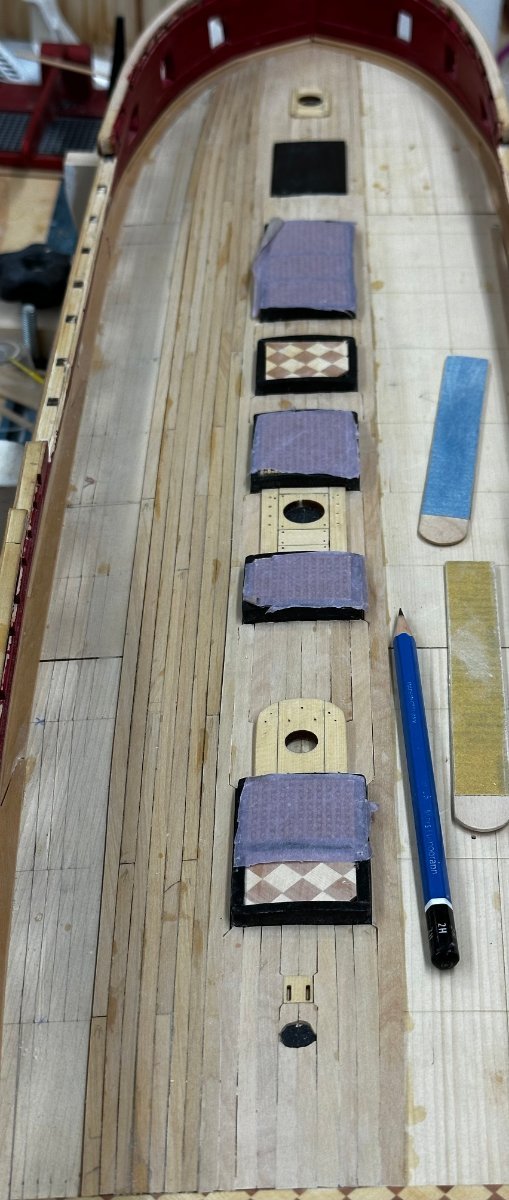
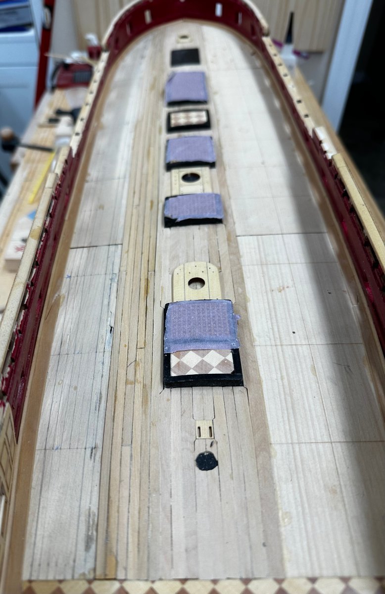
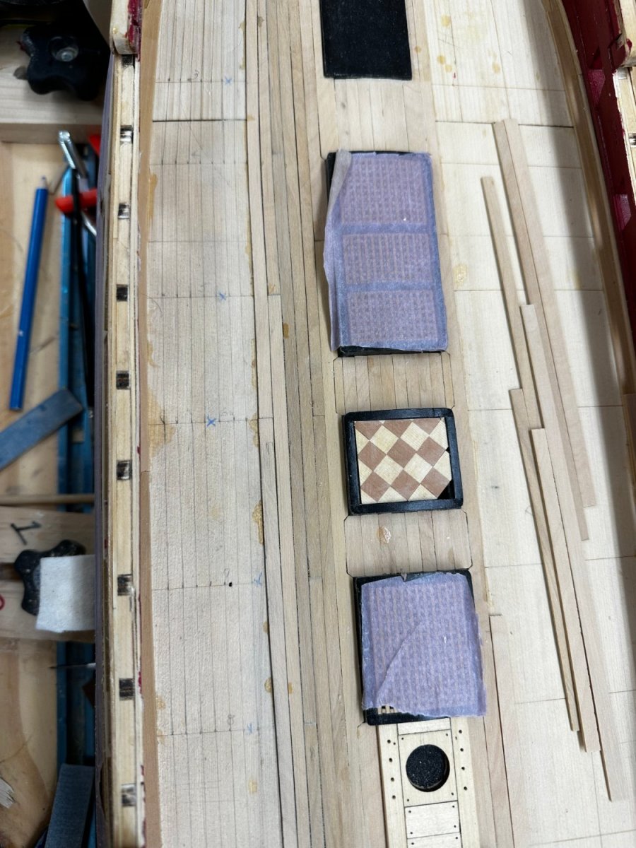
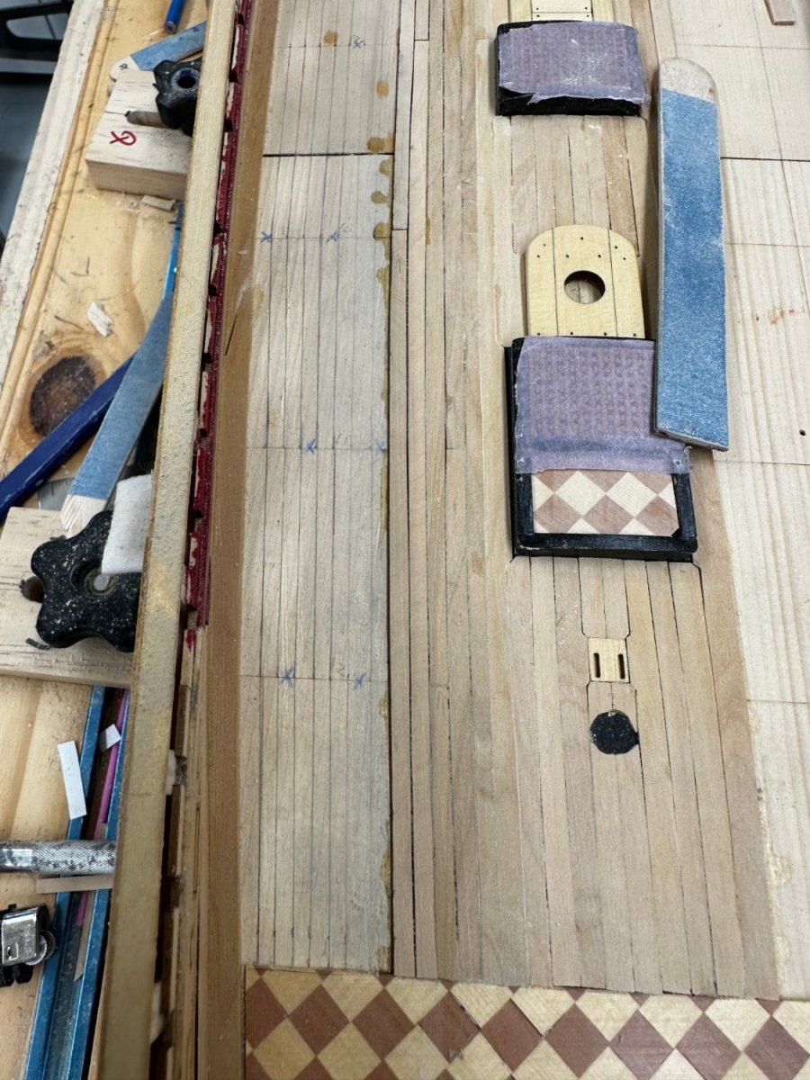
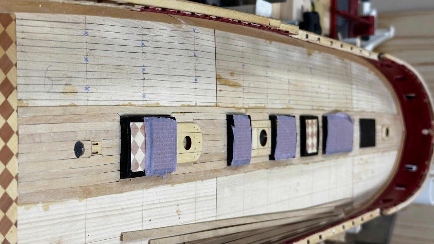
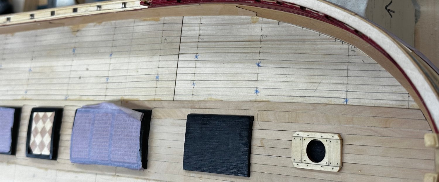
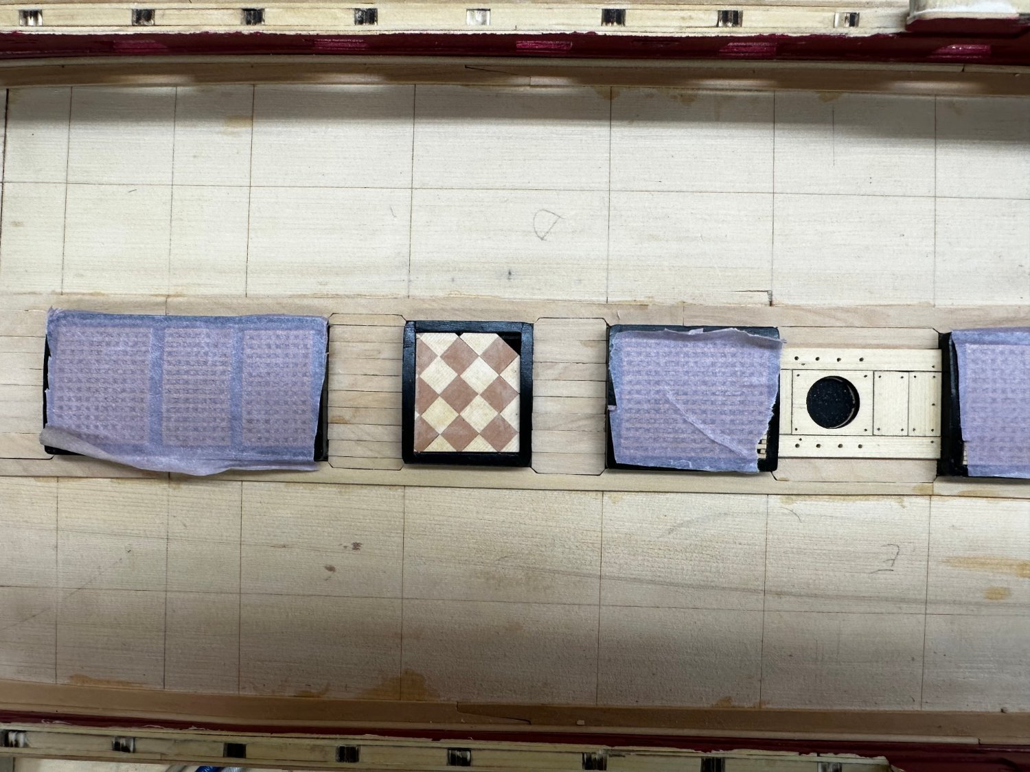
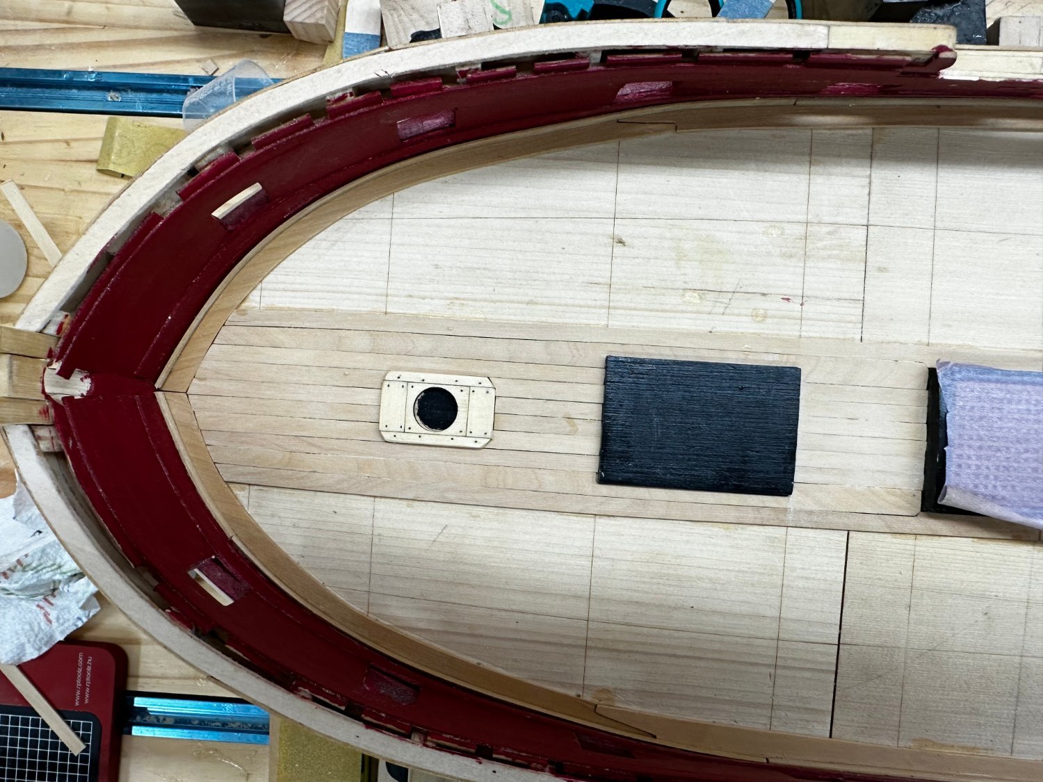
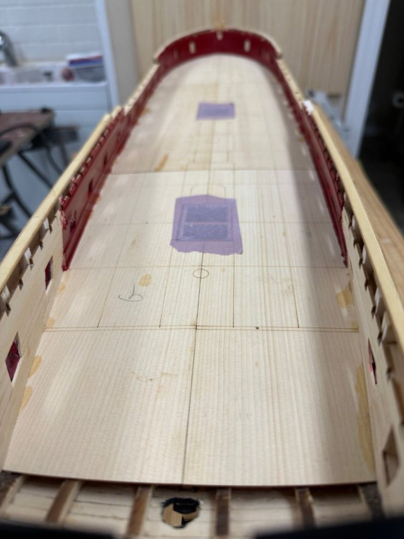
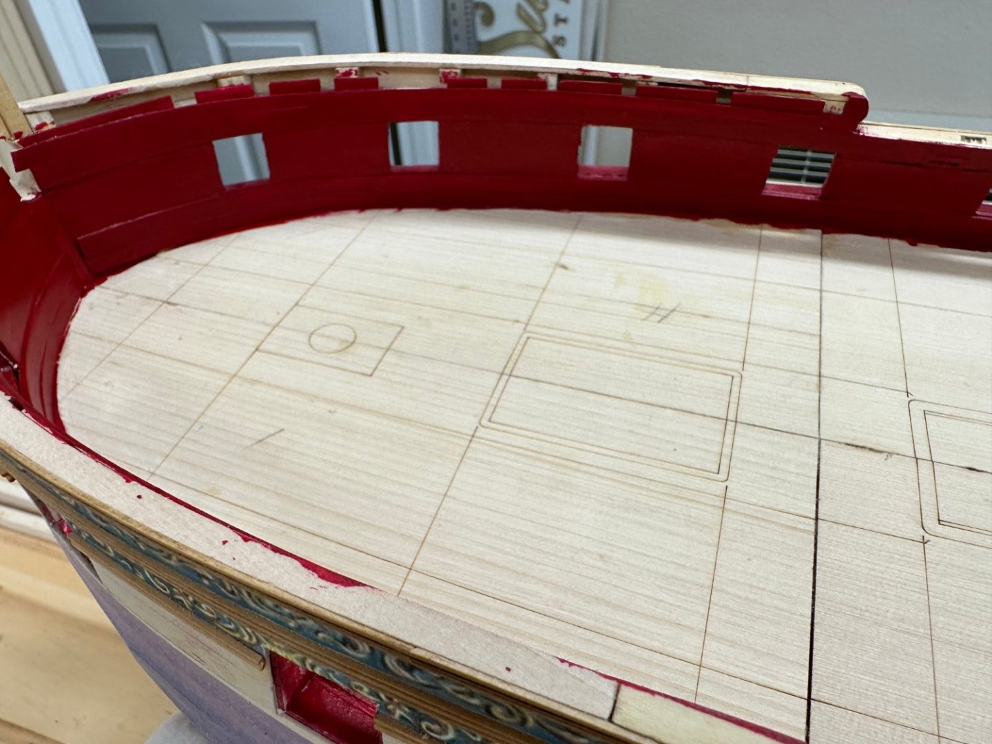
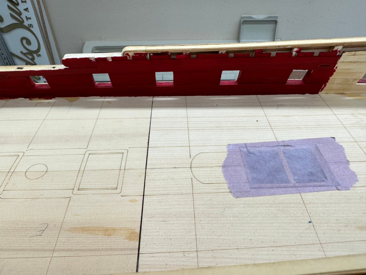
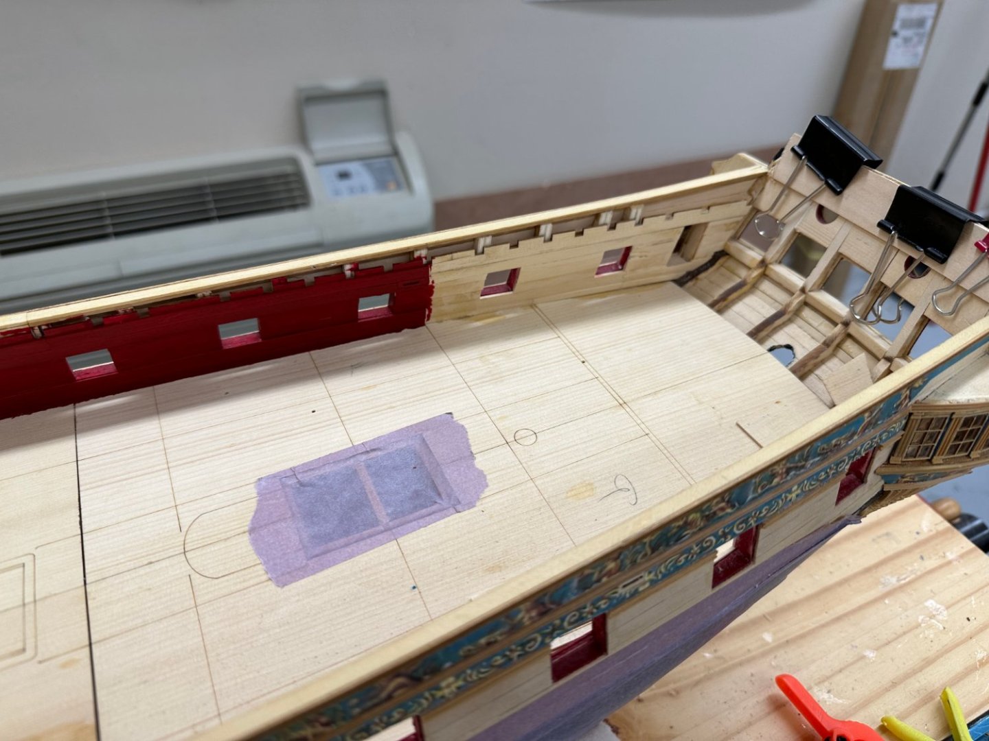
Since I am using 3/16" planks instead of 1/4" I had to adapt the deck lining to that fact. So, I measured and it will take 7n planks to cover the inner band and 6 for the outer. Using the tic strips and planking fan I marked off the deck similar to hull. I used the thin (1/16" wide) tape as per the monograph but I must be using an inferior grade of tape as I singularly unsuccessful in drawing lines along the "good" side. The pencil (mechanical with .05mm lead) kept riding over the tape. I finally pulled all the tape off and "connected the dots" using a ruler making the lines "piecewise linear" but I doubt my plank shaping skills would be able to follow anything else. I will have to "adapt as I go along" if things start to look to goofy. I plan to dry fit at least three planks ahead before resorting to glue. You will notice at the bow that I will need more than one hooked scarph. The drawing shows four at the bow and one at the stern. Here is the deck lined off on the port side. I thought I would do one side at a time in case I learn something that might be useful on the other side.


- 389 replies
-
- 4
-
-
- winchelsea
- Syren Ship Model Company
- (and 1 more)
-
Centerline planking completed. I took the cowards way out and used 1/4" and 3/16" pieces (and a few other custom widths) to get to the lines etched on the false deck (more or less). Now the real fun begins.


- 389 replies
-
- 5
-
-
- winchelsea
- Syren Ship Model Company
- (and 1 more)
-
Thanks Jim - yes quite the operation. Narrator said our ship (Norwegian Bliss - 160,000 tons and 1080 ft long) paid $1.2M for the transit. I think I saw a steam shovel or two in pictures of the canal construction but most of the Culebra Cut (connecting Gatun Lake to the Pacific) was pretty much pick and shovel work (after the jungle was cleared out). Interesting that the canal runs also North/South with the Caribbean on the North side. I always got confused about which way was which (on the map).
- 389 replies
-
- 2
-
-
- winchelsea
- Syren Ship Model Company
- (and 1 more)
-
Back from trip through Panama Canal and back at work on Winnie decking. I have the starboard side decking completed out to the first piece outboard of the hatchways/etc. I am using boxwood instead of AYC and ran a paint thinner rag over the decking just before taking the pictures. A good deal of sanding and fitting required. On to the port side and then the "real fun" begins - lining off the deck.

- 389 replies
-
- 6
-
-
- winchelsea
- Syren Ship Model Company
- (and 1 more)
-
No Winnie work for three weeks while I take a trip from Florida through the Panama Canal to Los Angles (and then fly back home).
- 389 replies
-
- 4
-
-
- winchelsea
- Syren Ship Model Company
- (and 1 more)
-
Glenn, Yes I have the monograph and have chosen to go with 3/16" planks instead of 1/4".
- 389 replies
-
- 1
-
-
- winchelsea
- Syren Ship Model Company
- (and 1 more)
-
Dry fit (except for the two center planks) of the decking forward of the triple hatchway. So far so good tapering the outer planks on each side to match the outline on the false deck.

- 389 replies
-
- 3
-
-
- winchelsea
- Syren Ship Model Company
- (and 1 more)
-
I looked at the drawing (sheet 4 of 4) again and it shows the planking done with 3/16" planks instead of the 1/4" called for in the instructions. That accounts for the additional plank between the hatch coamings. I checked with Chuck and he said it is my choice which width to use both are within the custom for this period (12" or 9" wide deck planks) Since I am cutting the deck planks "as I go" it is just as easy to cut 3/16" as 1/4" and if I go with 3/16" then I can use the drawing to get plank widths (or at least check what the tick strips/planking fan produce). So I pulled up the 1/4" planks and substituted 3/16" planks (one on each side of the centerline per the drawing). I find it easier to get them lined up correctly this way since you can see the centerline while placing the first one. Now to fill in the areas between the coamings and then move on to lining off the deck.
- 389 replies
-
- 4
-
-
- winchelsea
- Syren Ship Model Company
- (and 1 more)
-
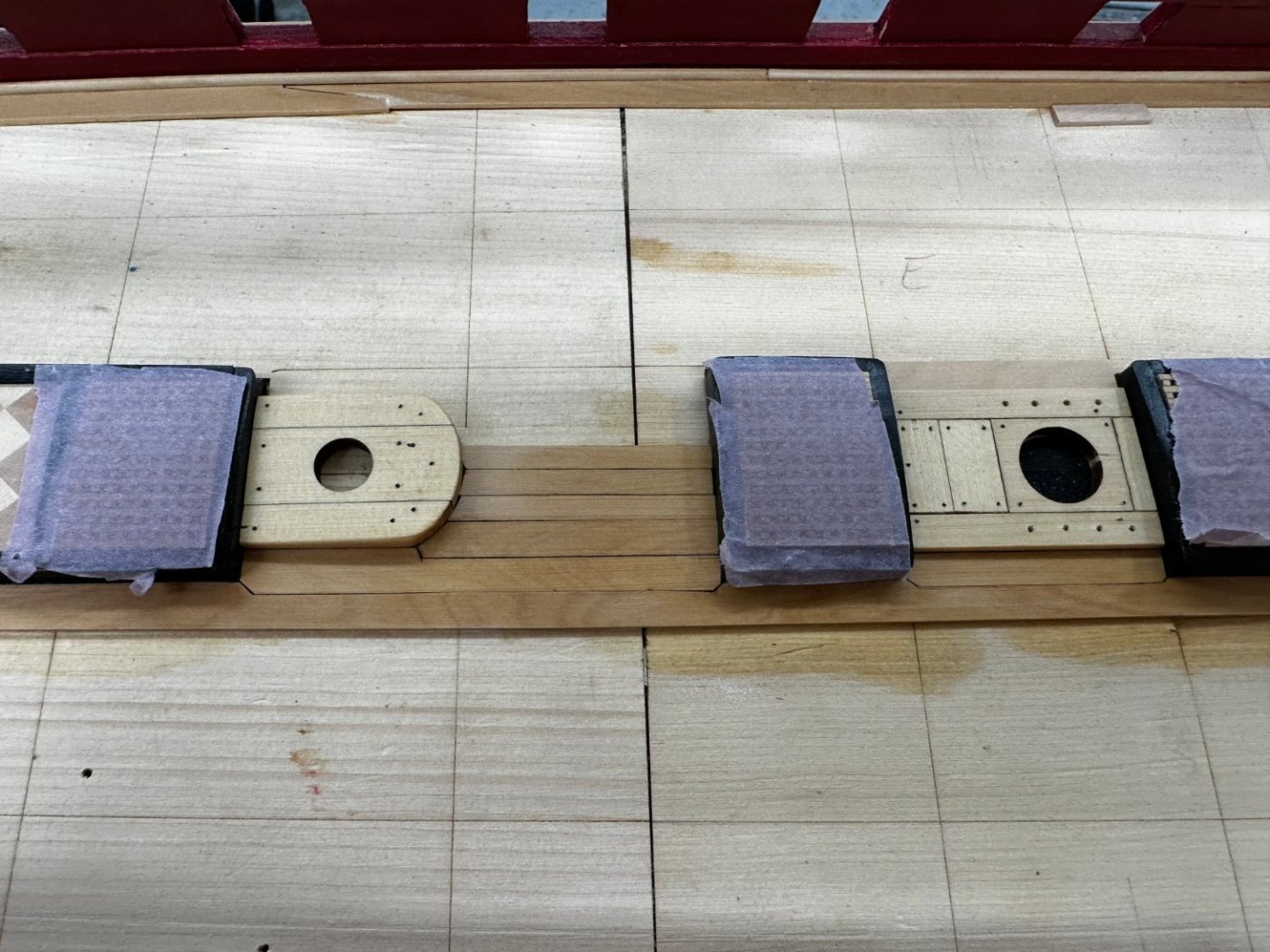
Centerline components glued down and centerline 1/4 X 3/64 Boxwood strip installed. I also painted the mast holes flat black in case I decide to not add the stub masts. Now the tick strips, planking fan, thin tape and all that fun. Probably should do a good "sweep down fore and aft" as they used to say in the USN before I start the planking preps. For those who come later it is a good idea, before the centerline pieces are glued down to center a 1/4" wide plank and mark the outer edges so you will have a better idea where the short lengths of the centerline planking between the coamings are supposed to go. Once the plank is on the deck the centerline reference "disappears" and it is easy (for me) to get them slightly "off center". Also if you are using white or carpenters glue the piece can slide around when pressure is applied so check again after the pressure has been applied to make sure it didn't move. That will be much easier if you have lines on each side of the centerline to look at. One other point "of order". As best I can tell the drawing (sheet four of four) does not show a centerline plank, but a plank on each side of the centerline. It would appear that the drawing is not going to be much help with the tabbed planks and such as there are an even number (6 or 😎 planks between the coamings on the drawing. Am I missing something?

- 389 replies
-
- 6
-
-
- winchelsea
- Syren Ship Model Company
- (and 1 more)
-
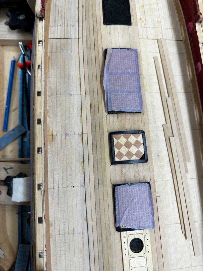
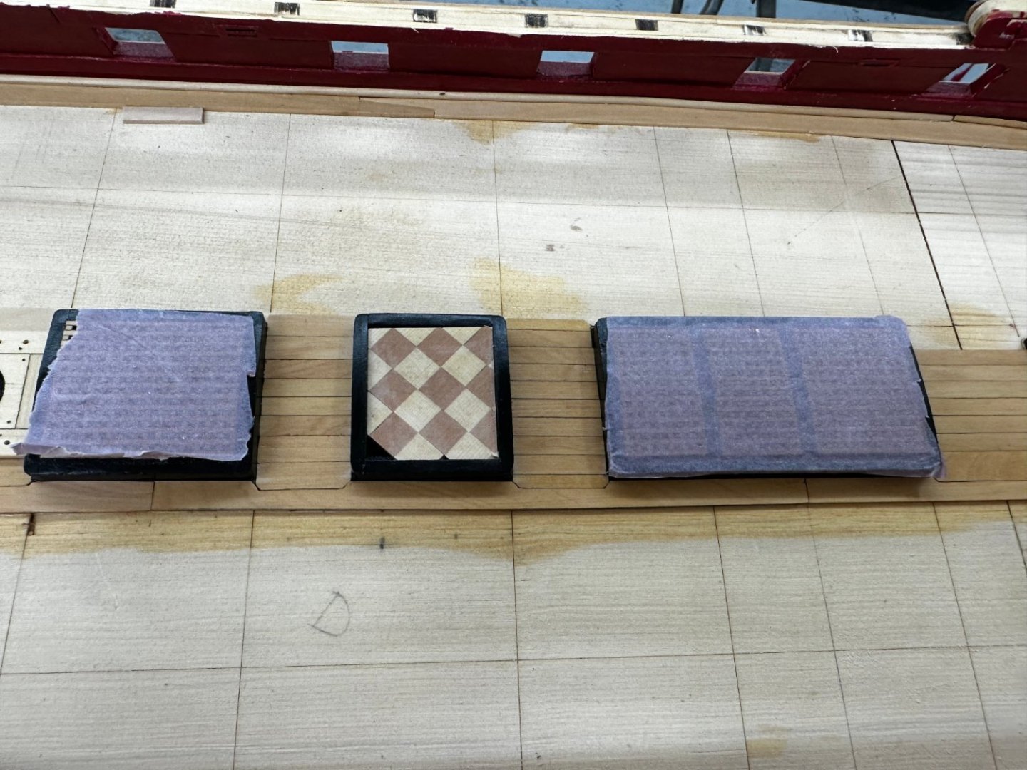
I got the margin planks completed and glued down the checkered flooring. Waterway were more of a challenge. Instructions said to use 3/64 X 3/64 with the "edge angled on the inboard side or you can fashion it into the typical quarter round molding shape". I used 1/16 X 1/16 boxwood and used the 2mm X 2mm molding cutter to fashion it into quarter round. Since 1/16 is a bit less than 2mm I think it yielded something close to the desired effect. Now on to gluing down the centerline components and "lining off the deck".
- 389 replies
-
- 4
-
-
- winchelsea
- Syren Ship Model Company
- (and 1 more)
-
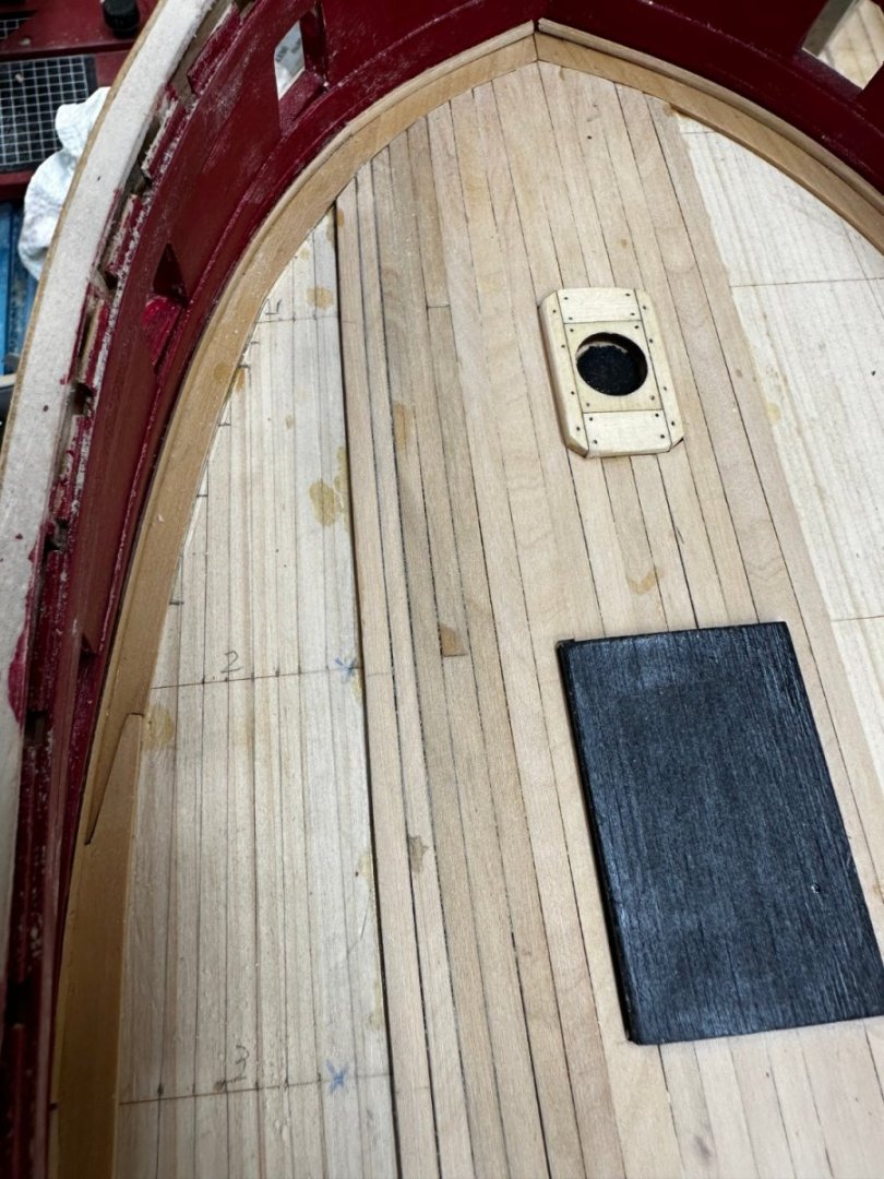
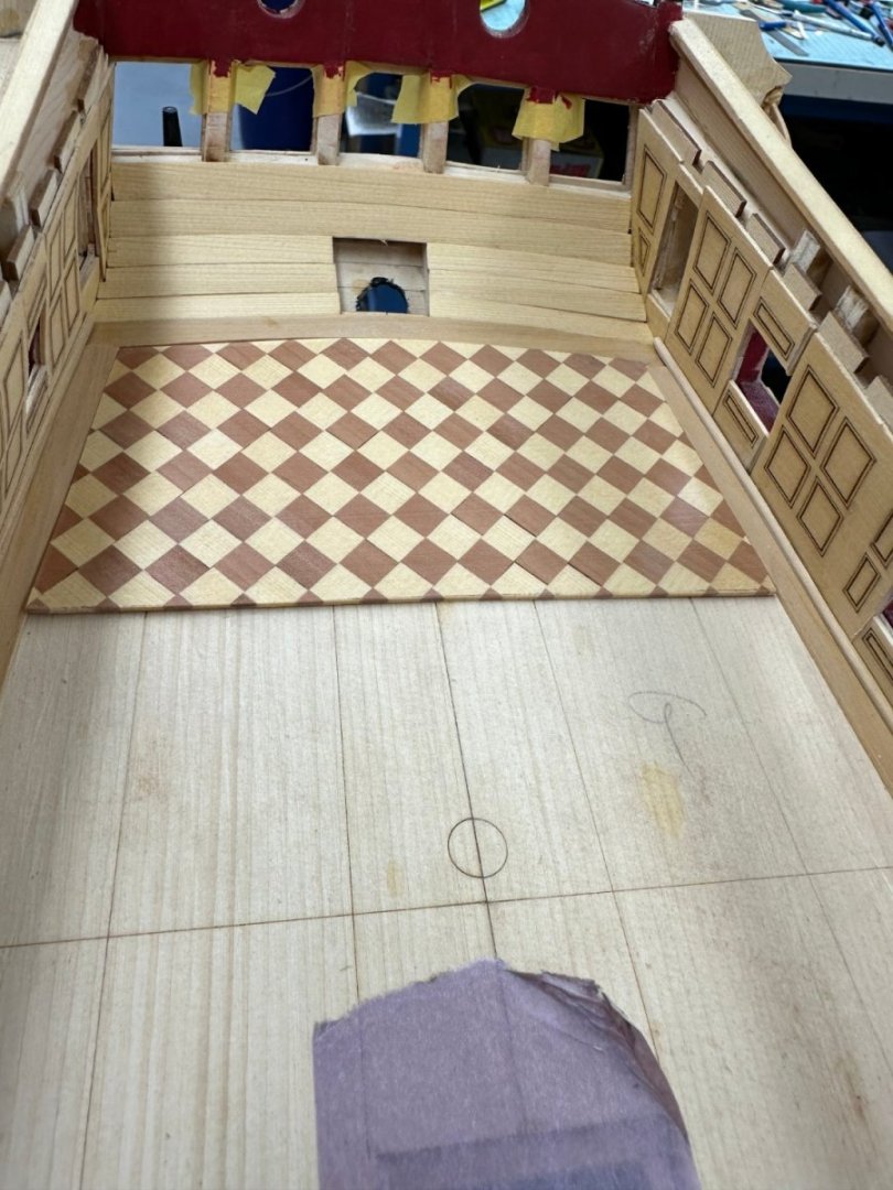
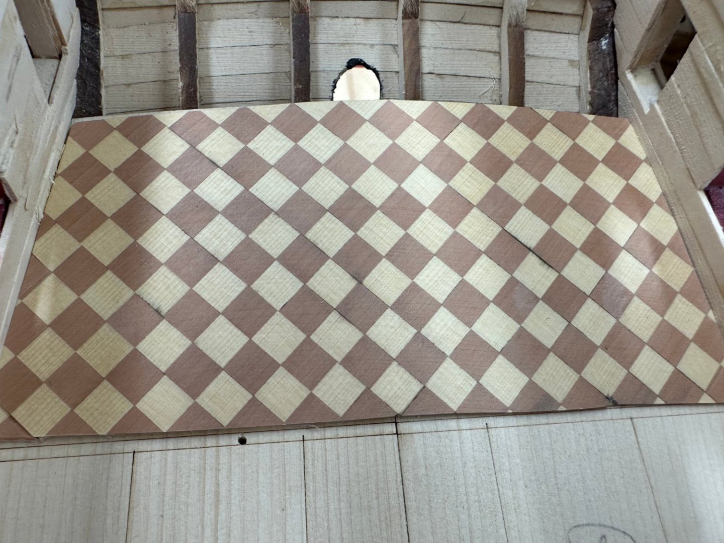
Dry fit of Great Cabin flooring. Will glue down when all the margin planks and waterways are done.
- 389 replies
-
- 5
-
-
- winchelsea
- Syren Ship Model Company
- (and 1 more)
-
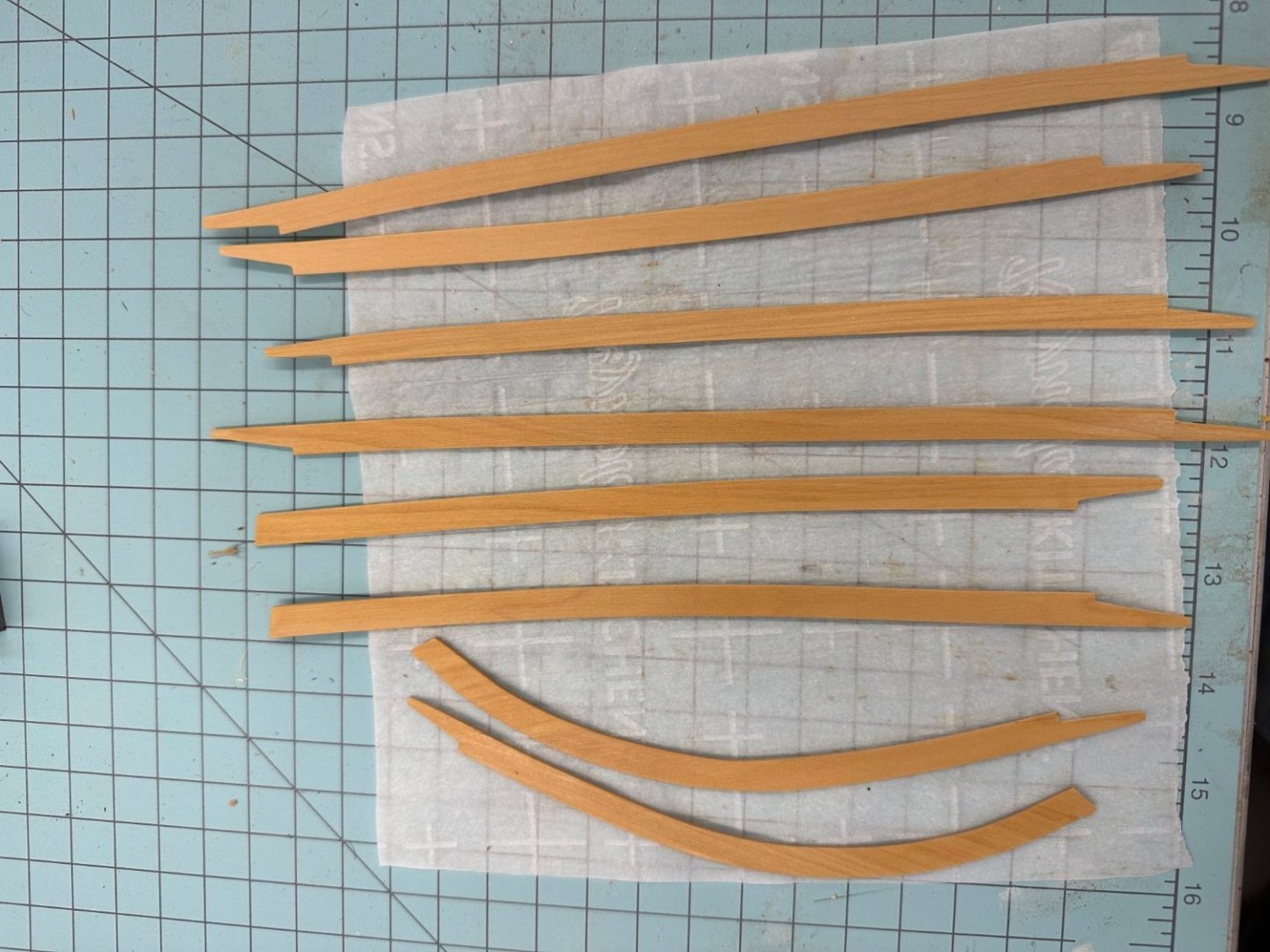
I have decided to plank the deck with boxwood instead of AYC. The first thing that has to change are the margin planks and waterways. I traced the drawings onto a sheet of 3/64" thick boxwood and then cut/sanded to the drawings. Fitting them to the deck took another few hours of fine sanding to get them to fit then a few more hours cutting the joints.As it says in the instructions the joints will be mostly covered all the guns/lines on deck but... Anyway here are the eight margin planks after a coat of WoP. I will put at least one more coat on before installing.
- 389 replies
-
- 5
-
-
- winchelsea
- Syren Ship Model Company
- (and 1 more)
-
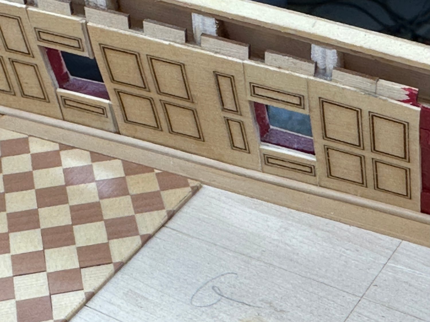
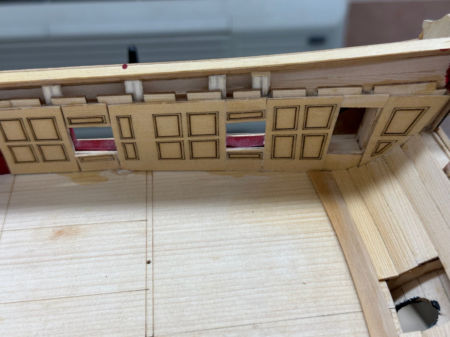
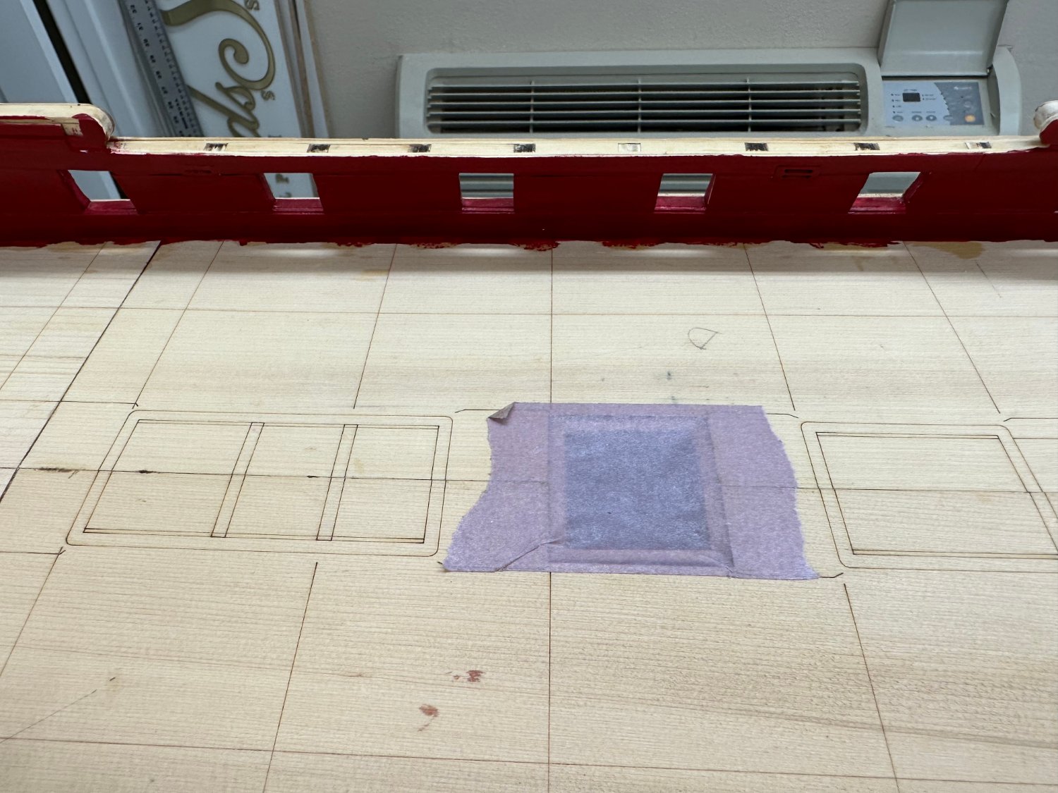
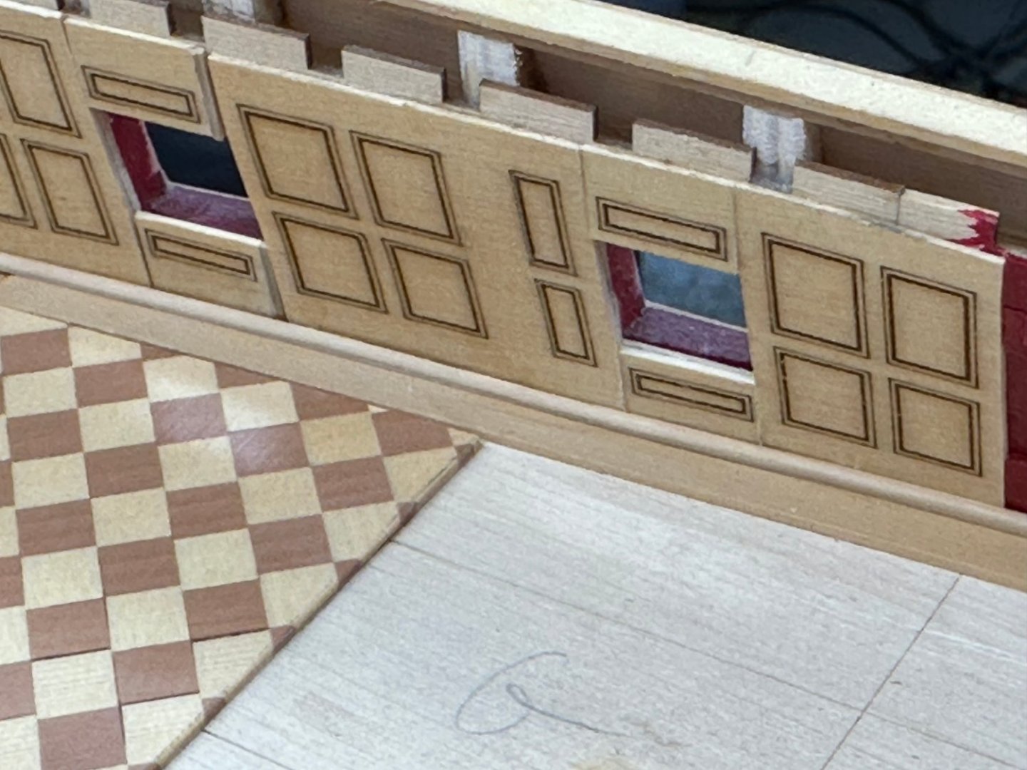
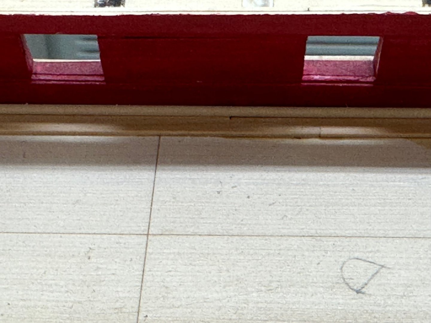
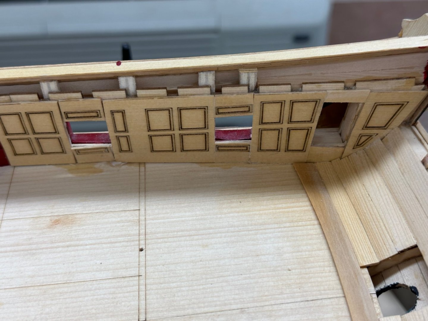
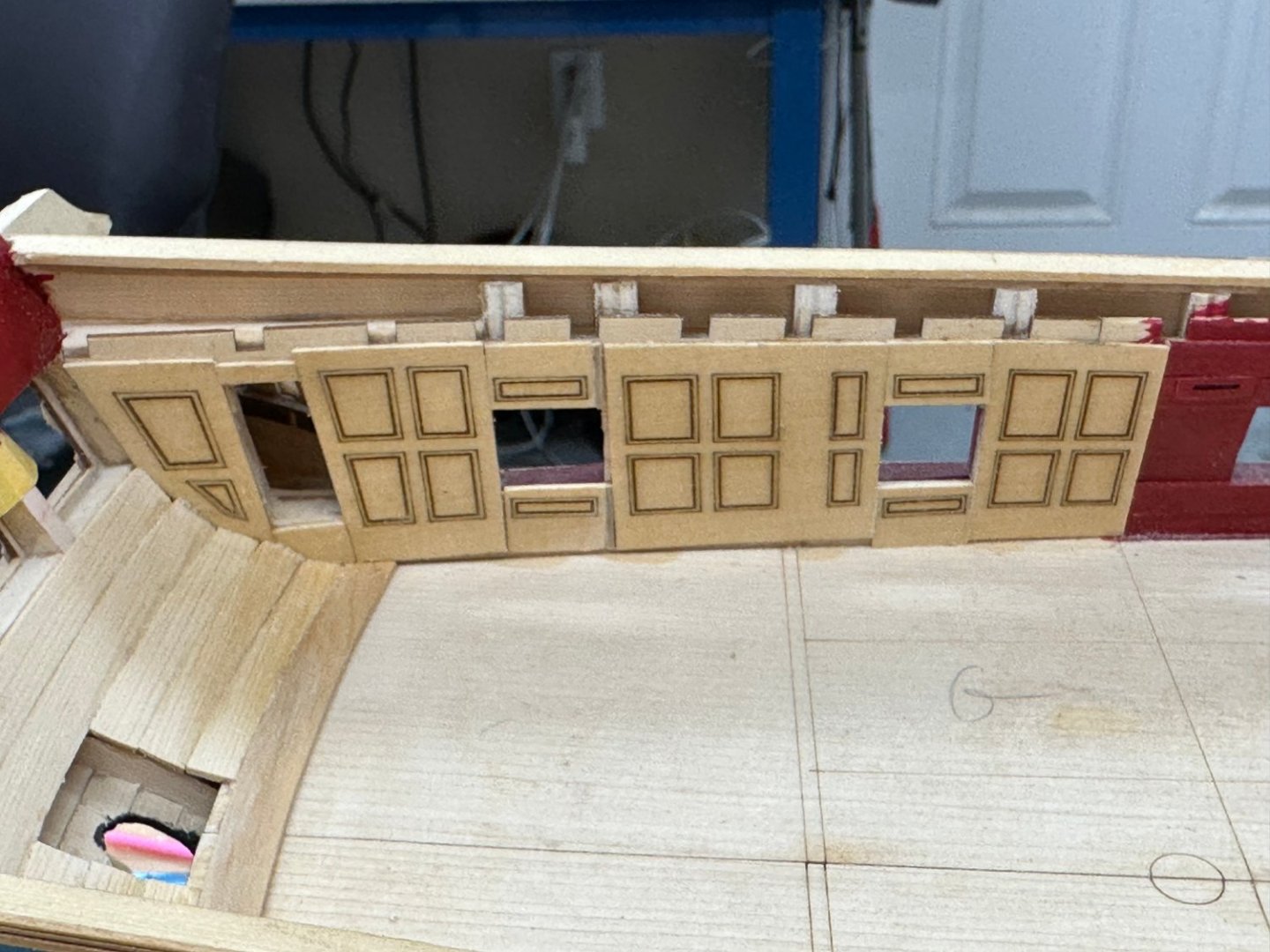
I have the panels installed in the Great cabin. My spacing was not perfect on either side (which I suppose is better than only on one side). I had to add a very narrow "slice" to the pieces between gun ports 13 and 14 on each side. I also messed up the lower piece on stbd gun port 13 - it went crocked on me when I put the clamp on. Probably not worth trying to fix as the will be a gun right is front of it. So here is the Great Cabin paneling: I also planked the lower transom, added the margin plank across the stern and painted the upper inner transom red. I figured it was better now then with any more "stuff" to get paint on. Will probably have to touch it up later - along with everything else. WoP for this area is next although I put three coats on the paneling before I installed it the margin plank and transom are "bare" at the moment.

- 389 replies
-
- 3
-
-
- winchelsea
- Syren Ship Model Company
- (and 1 more)
-
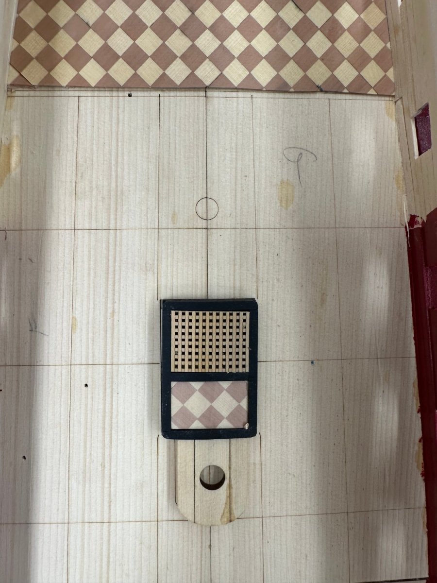
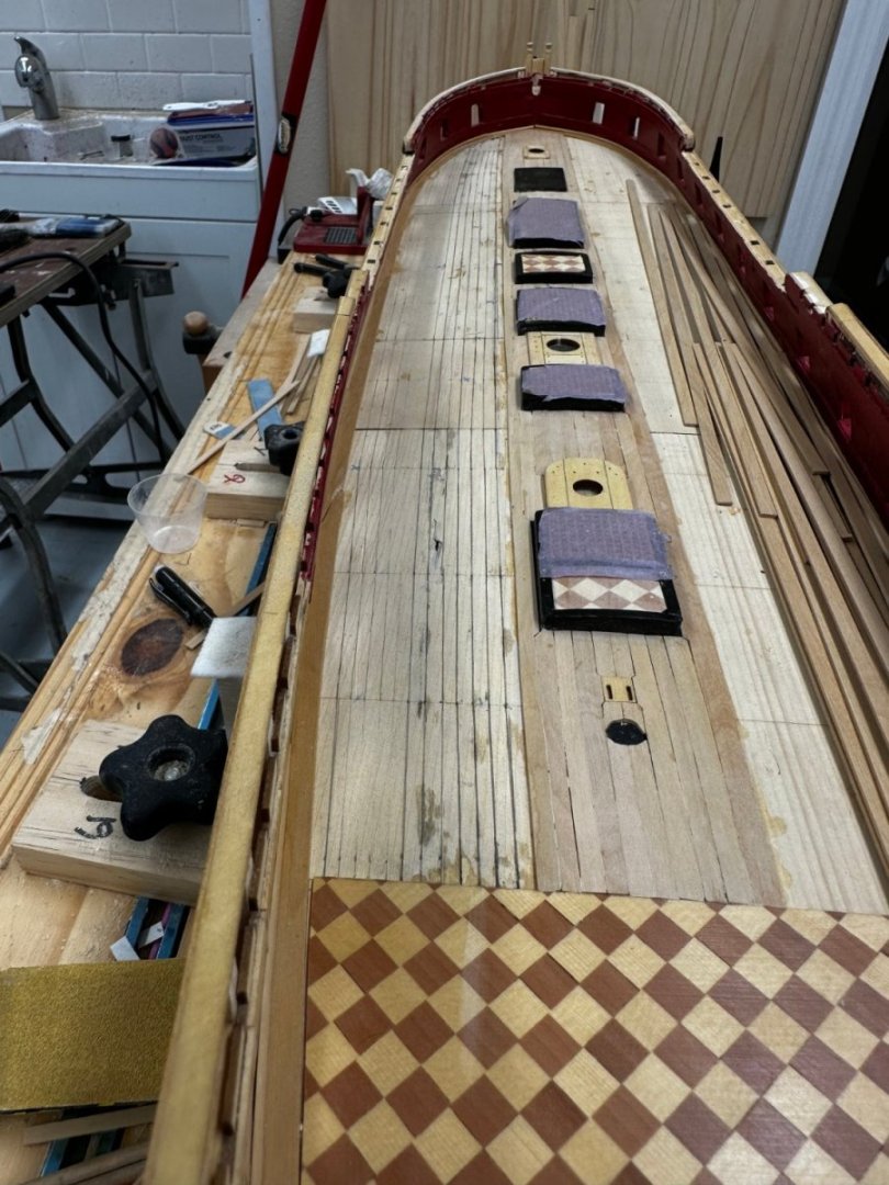
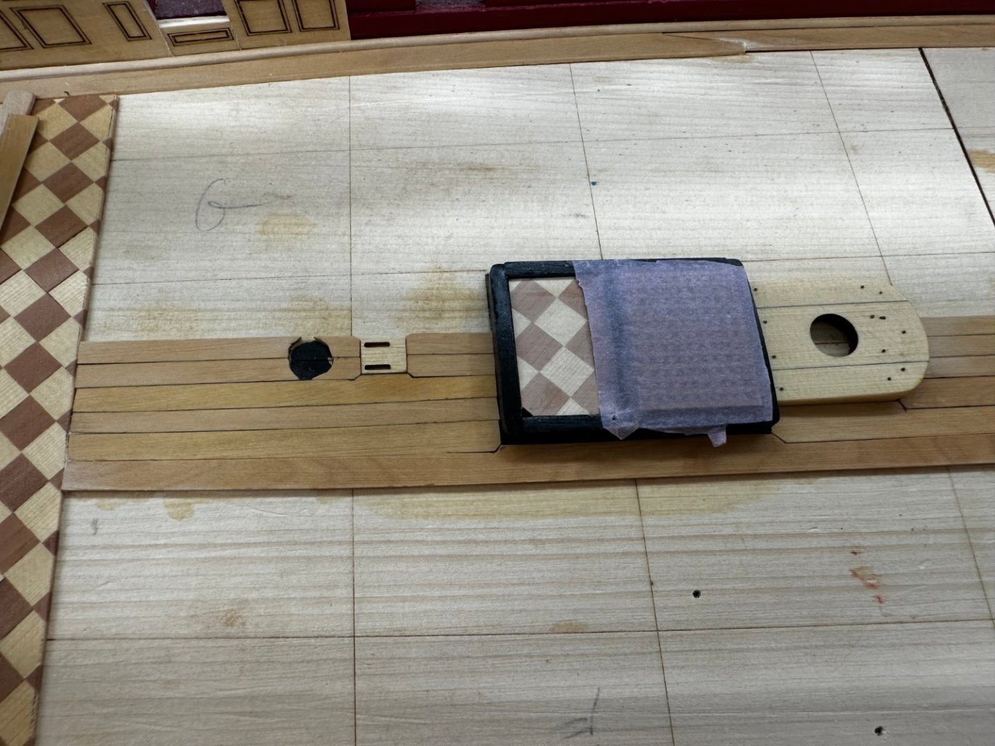
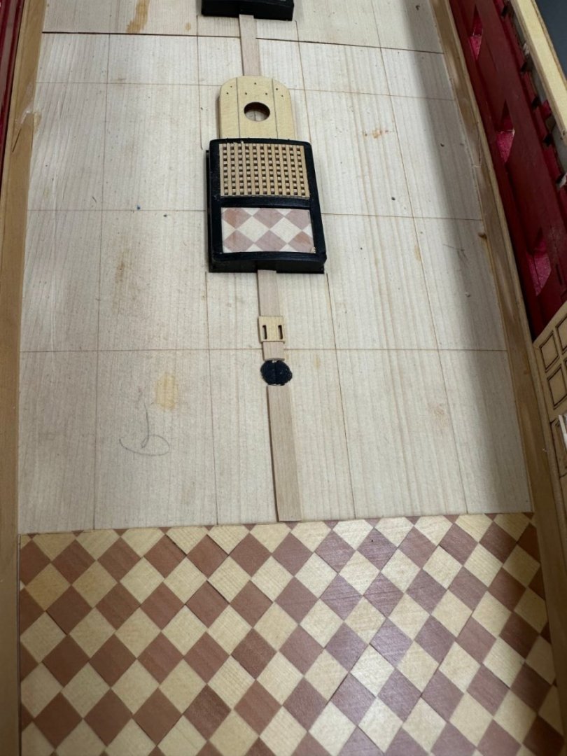
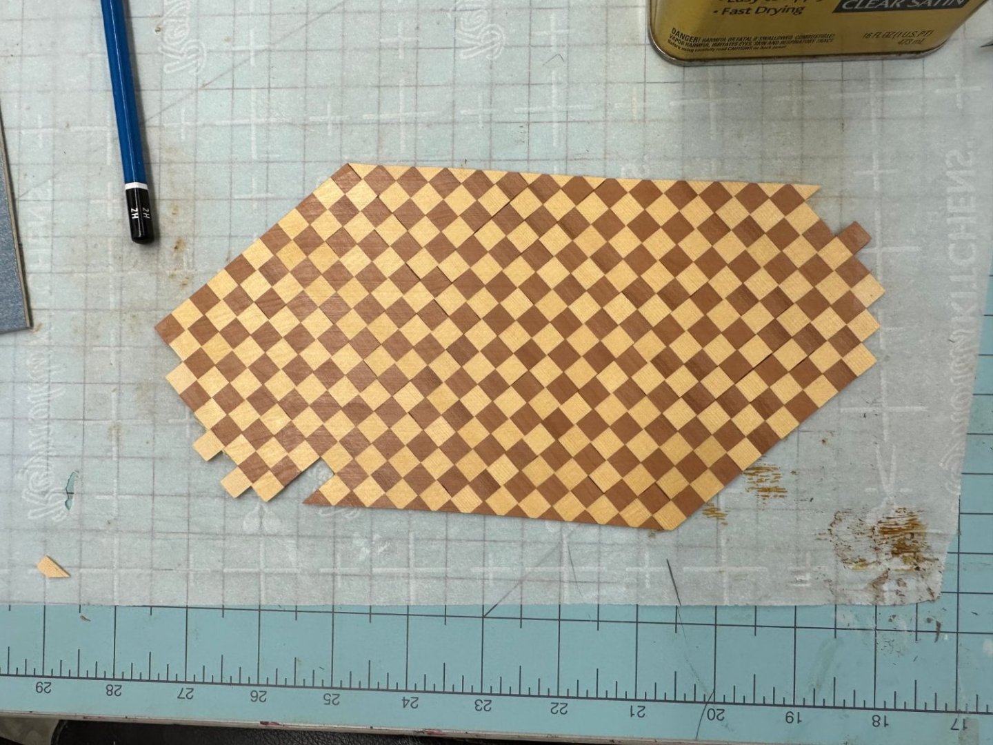
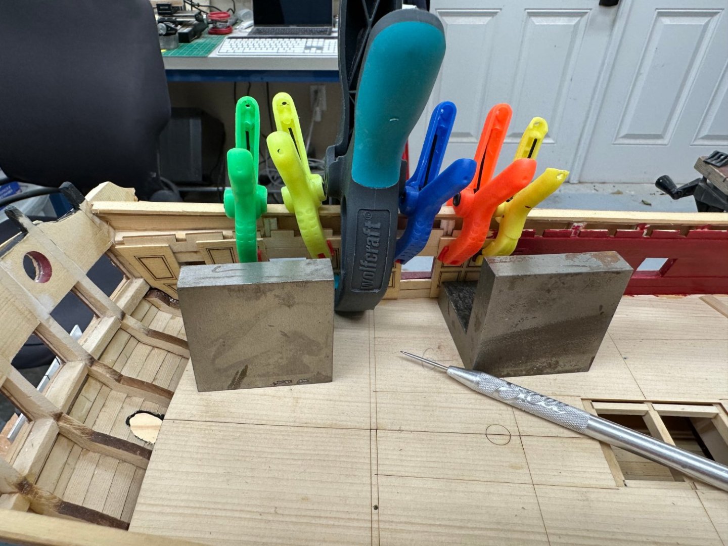
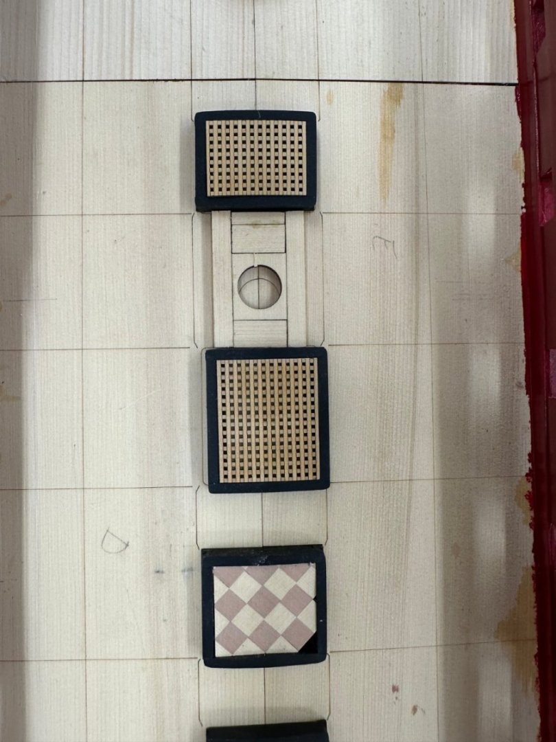
I am getting things a little out of order so am resorting to reading the instructions. I downloaded the chapter 4 material onto my iPad which I now have "close at hand" when my enthusiasm gets ahead of my better judgement. I hope to continue this "tactic" going forward. My printer/software combo does not render the pictures in the Chapter sections correctly much of the time making them less useful so we will shift to electronic. So I got all of the pieces that occupy the centerline completed and two coats of WoP on each. I almost forgot the little piece for the wheel ropes. I bought both 20# and 15# fishing line (you get 300 yds - a triple lifetime supply for a 20 year old non-fisherman for about $8 on Amazon). I used the 20# on the capstan partner and the 15# on the mast partners and I added the holes for the eight eyebolts on the main partner. Hard to tell the 15# from the 20# at least with my eyes. I decided to make a new attempt at a checkered floor. This time I started with 5/32" strips and did not thin it down until I had them in the checkerboard pattern. There are still a few areas that are not EXACTLY correct but it is better than my first attempt so I will use this one. And having received the new Great Cabin paneling I have the major pieces on the port side glued up. I had to resort to using machinist blocks to press the bottoms of the panel near the stern to avoid trying to use the q-gallery as an anchor point for a clamp.
- 389 replies
-
- 10
-
-
- winchelsea
- Syren Ship Model Company
- (and 1 more)
-
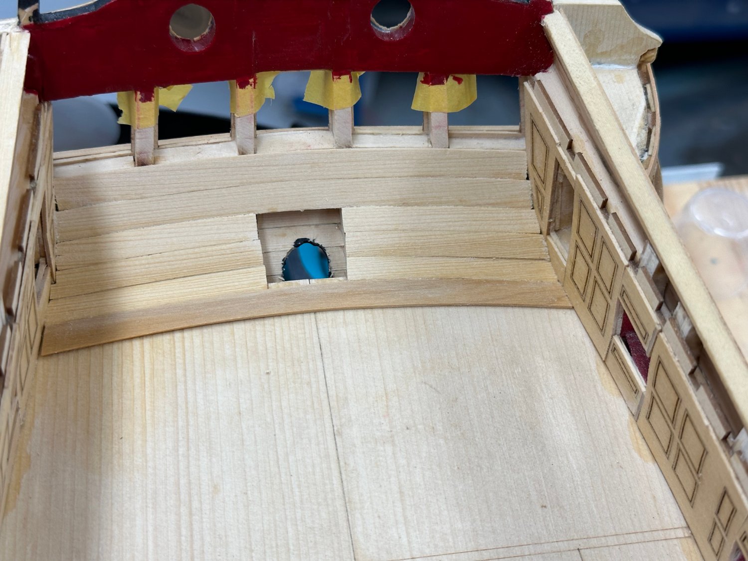
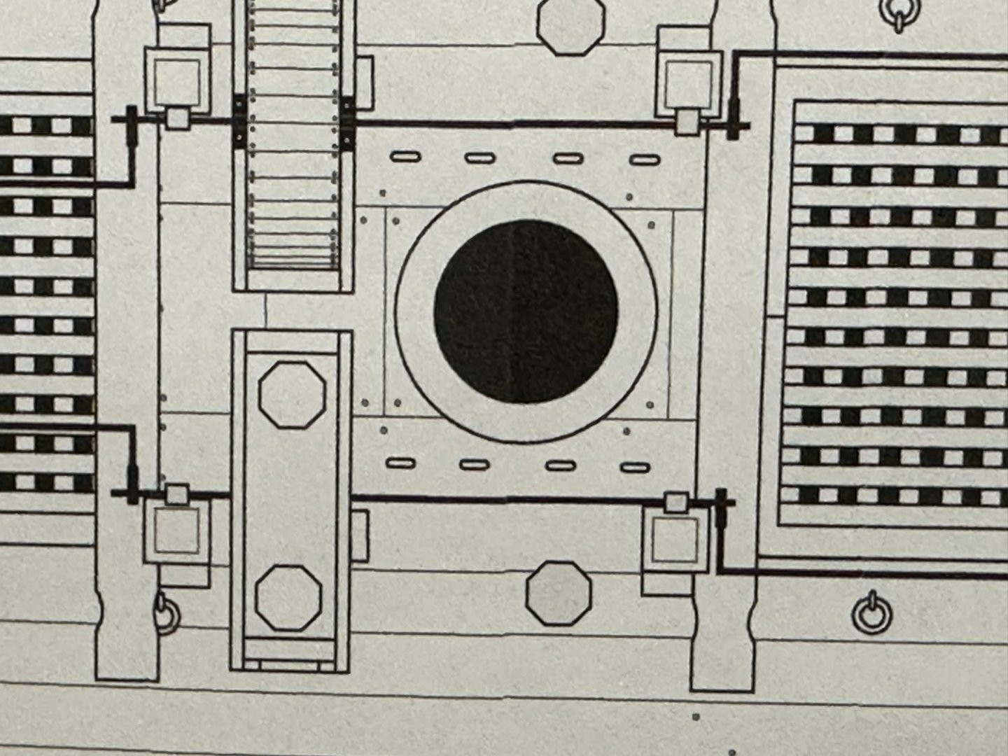
After looking at the picture of the main mast partner above I saw that the hole in the false deck and in the partner did not line up. I thought initially it was just the camera angle or parallax but the closer I looked the more I saw that I had assembled the partner incorrectly. Another case of the kit being ALMOST idiot proof. It is easy to identify the hole for the mast and the two side pieces. There are three other pieces, two roughly the same size and one considerably shorter (in the fore/aft dimension). I put a big one on one end and a big one and the short one on the other end. From the drawing see below it is not all that obvious (to me) that only the short one goes on one end and the two longer ones on the other. So I took the main mast partner apart and re-glued it correctly. Given that there are not even stub masts on the Winnie (if built per the instructions) I might never have noticed the error if not for the picture.
- 389 replies
-
- 2
-
-
- winchelsea
- Syren Ship Model Company
- (and 1 more)
-
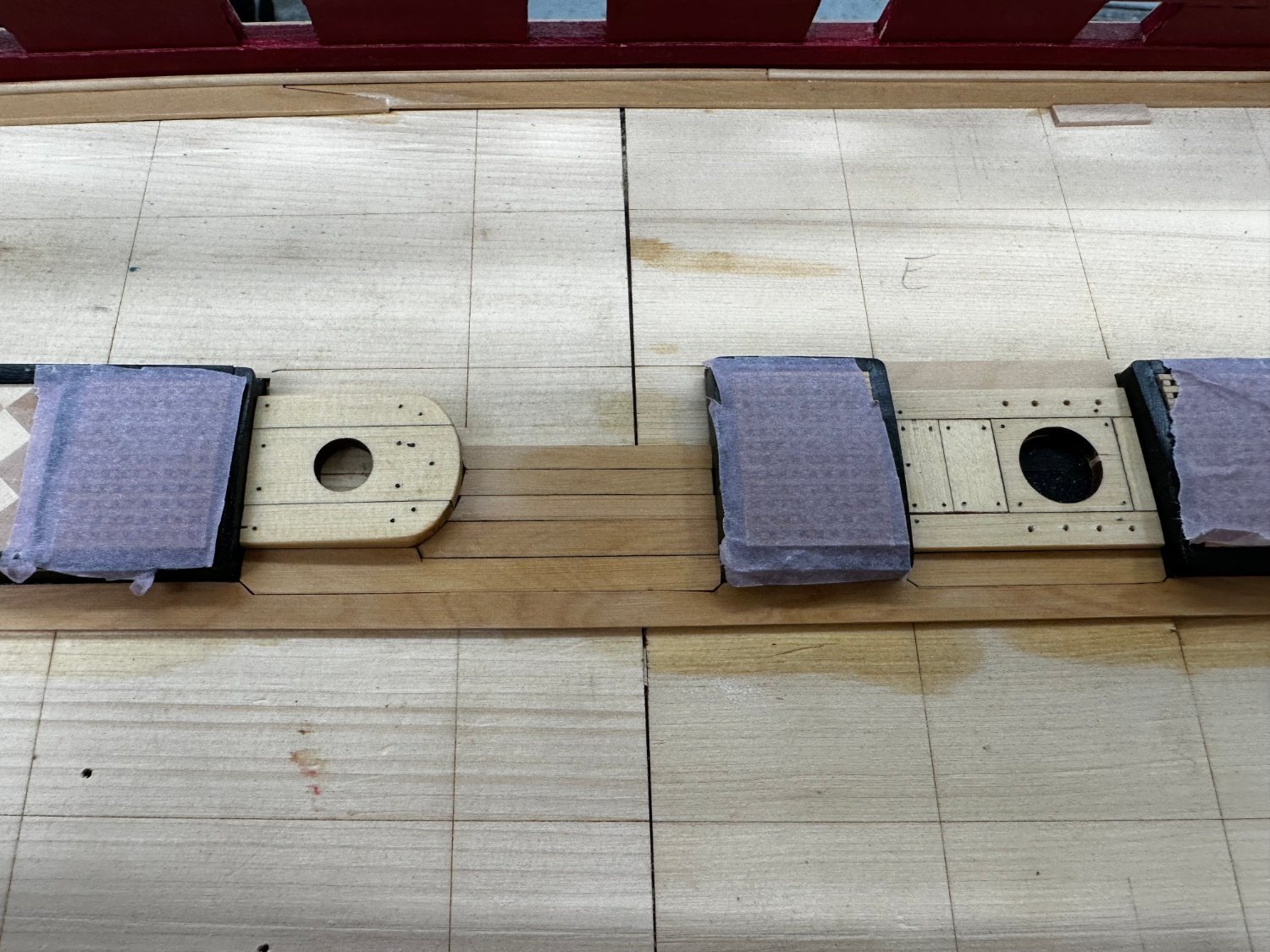
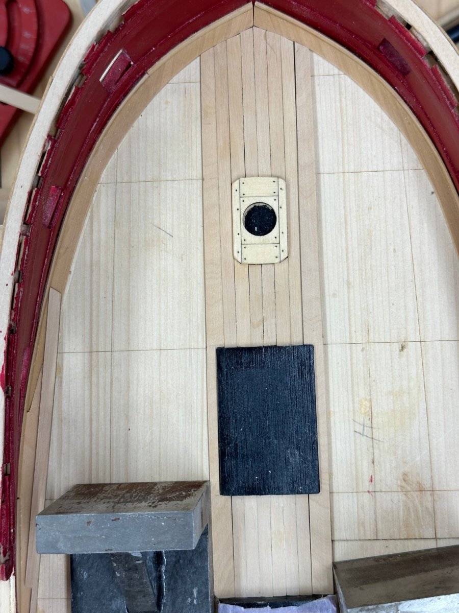
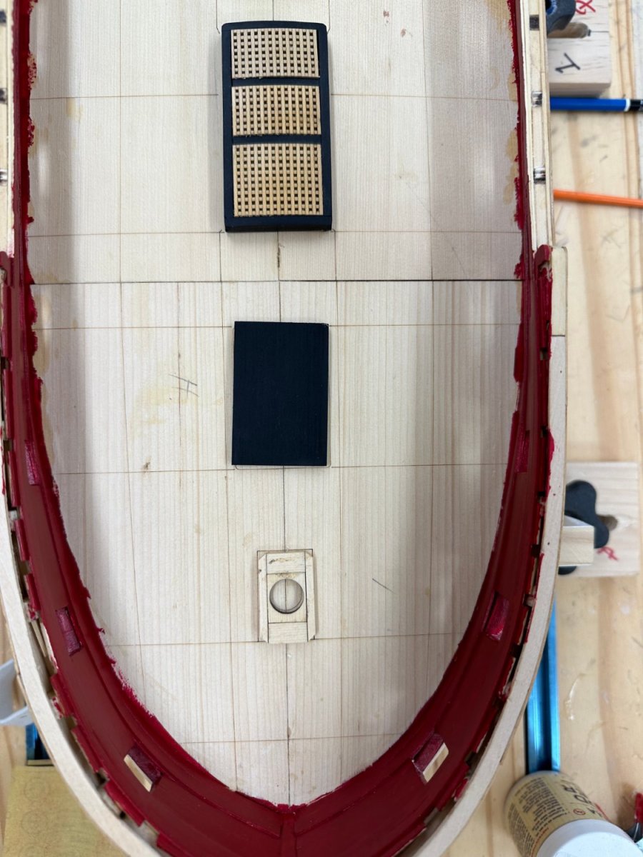
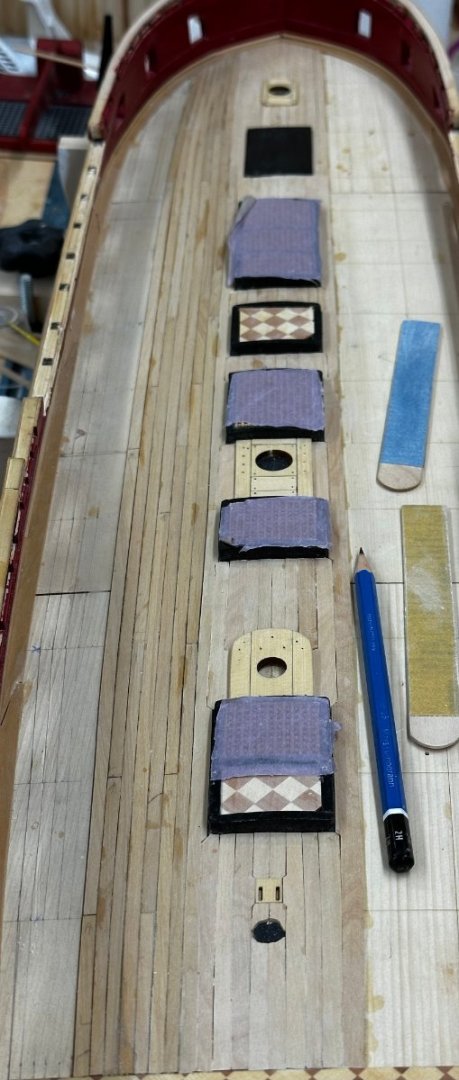
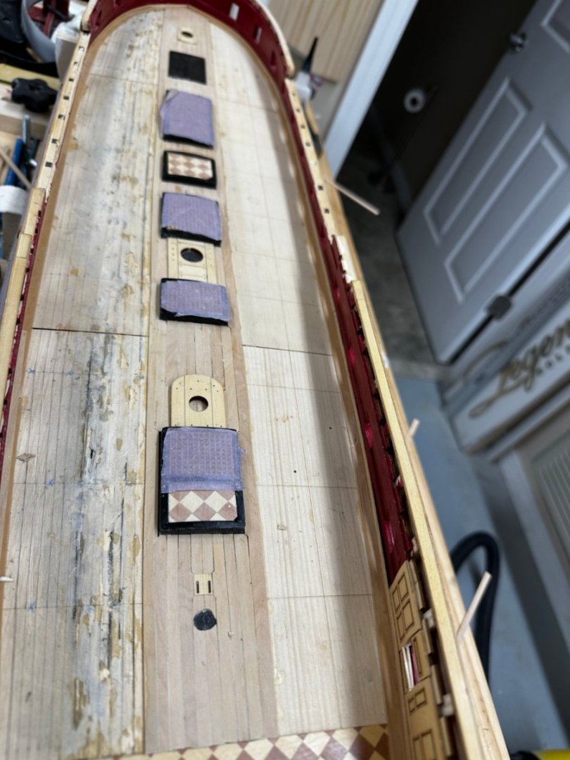
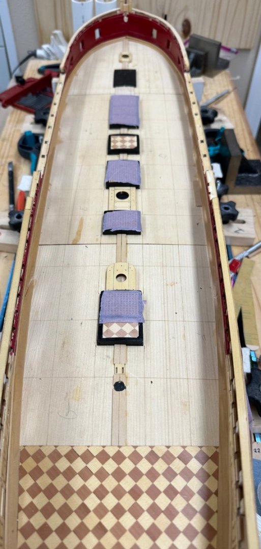
All of the hatch coaming, mast partners and capstan partner are "on deck (dry fit). I have not detailed the partners yet but the coaming have two coats of flat black and are as ready as they are going to get. I fabbed my own Great Cabin deck but am not sure I am going to use it. There are two small areas where the glue soaked through and try as I might I could not remove the residue (which turned black for some reason). This is with one coat of WoP and I fear it may get more noticeable the more WoP is applied. I can still use the kit provided deck and I put a coat of WoP on it as well to see how it will look. And of course the areas of concern are more or less in the middle. I may try another fab starting with thicker stock so glue soaking through is less likely or... Here are the partners and coamings in place.


- 389 replies
-
- 4
-
-
- winchelsea
- Syren Ship Model Company
- (and 1 more)
-
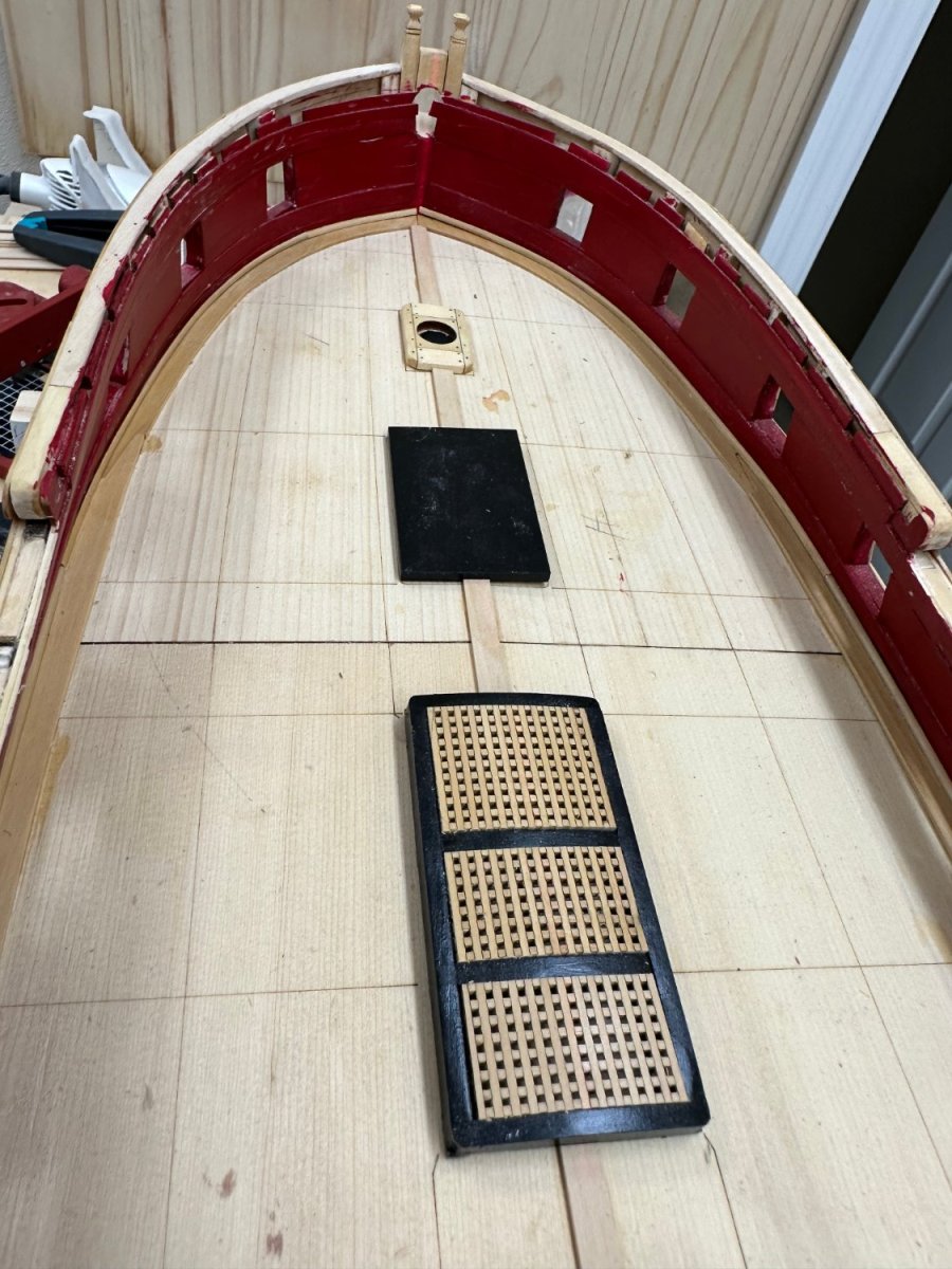
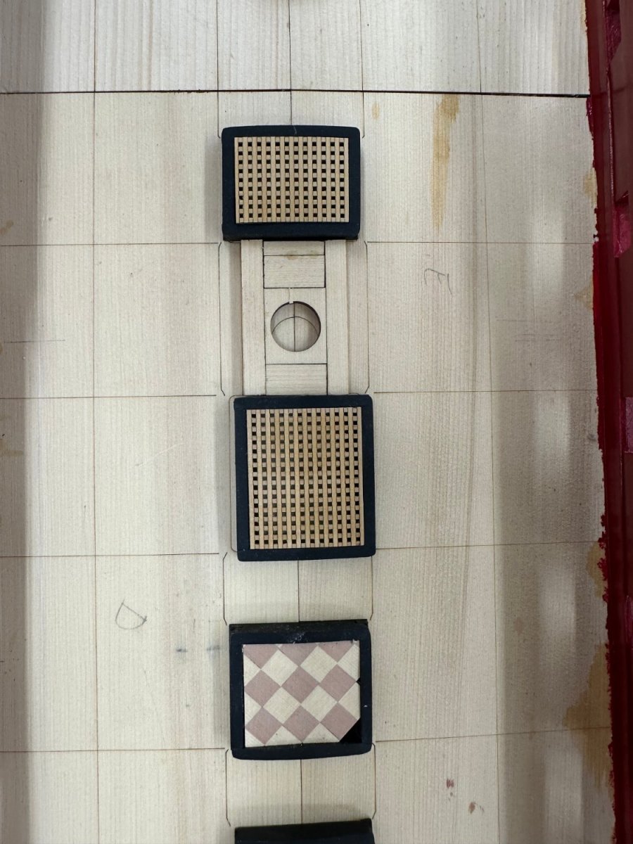
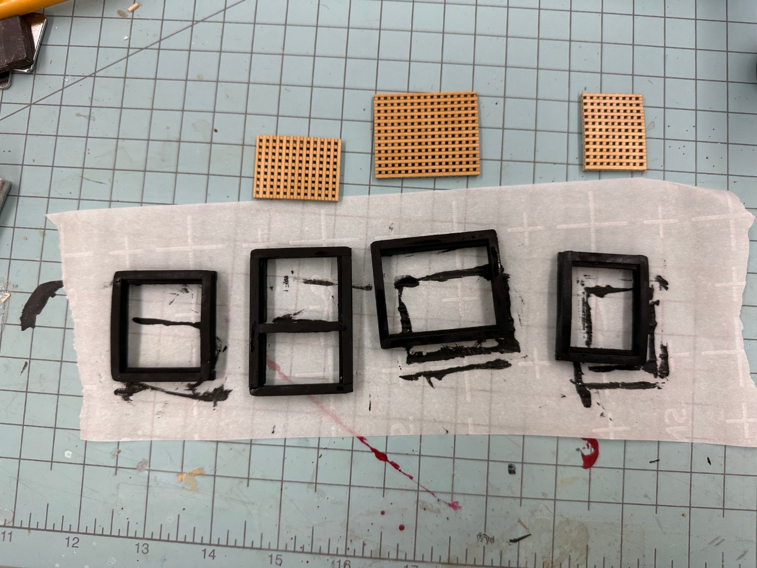
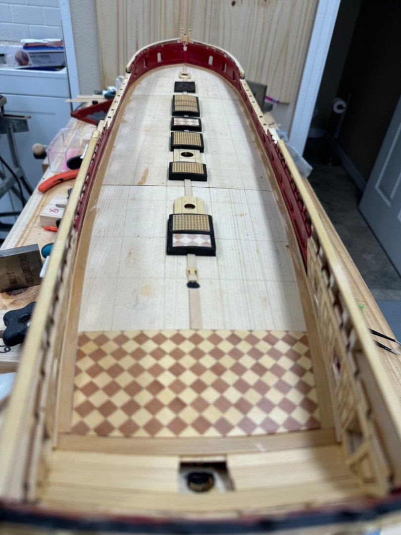
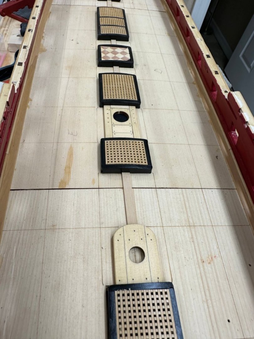
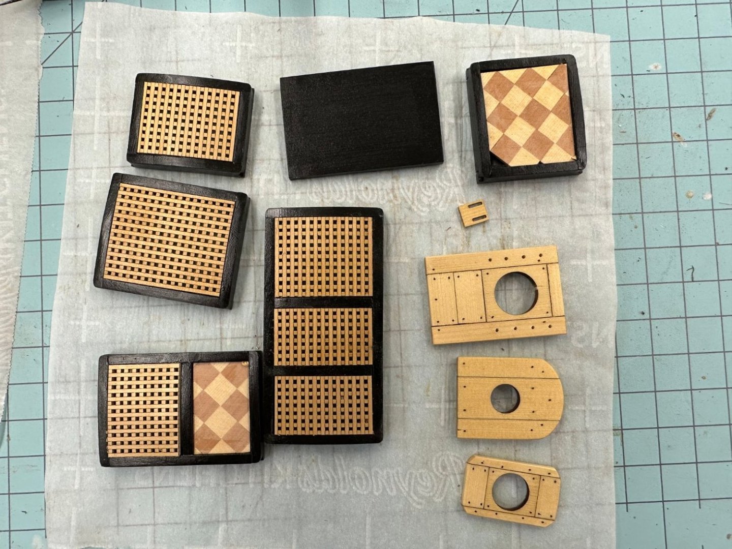
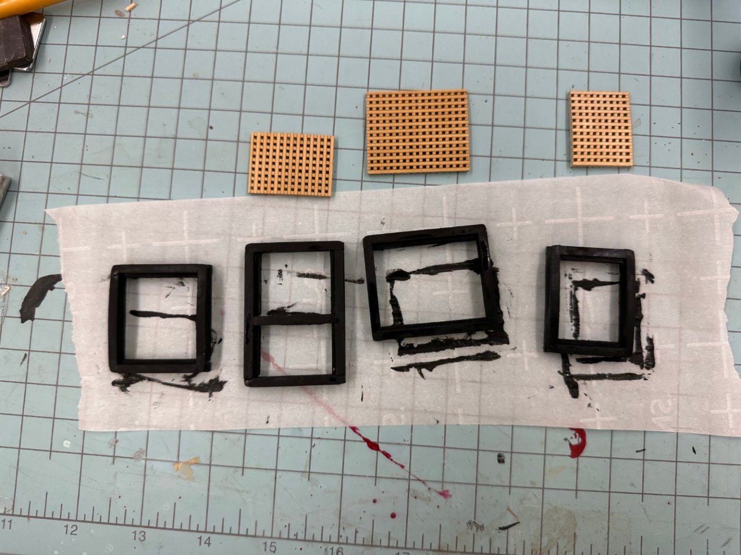
Compared to some other kits I have built the hatch coamings here are ALMOST idiot proof. I followed the instructions and successfully built four of the five coaming being careful to make sure the two halves would "go together" to form a rectangle. I did not take into account that the one hatch with two intermediate members requires a bit more thought as the two halves are laid out. I had a 50/50 chance of dumb luck saving the day but alas... Here are the four successfully assembled (and painted) hatches and the gratings for them. I made these boxwood gratings months ago as a break from assembling the hull structure. I did not measure I just built them bigger than needed based on the drawing. I have the quarterdeck hatch gratings ready as well in AYC. I will have the fifth hatch done tomorrow (I hope).
- 389 replies
-
- 8
-
-
- winchelsea
- Syren Ship Model Company
- (and 1 more)
-
Three coats of Windjammer Red. Hopefully the new Great Cabin panels will be here Wednesday. In the meantime I am keeping busy with the hatch coamings and the Great Cabin floor.

- 389 replies
-
- 4
-
-
- winchelsea
- Syren Ship Model Company
- (and 1 more)
-
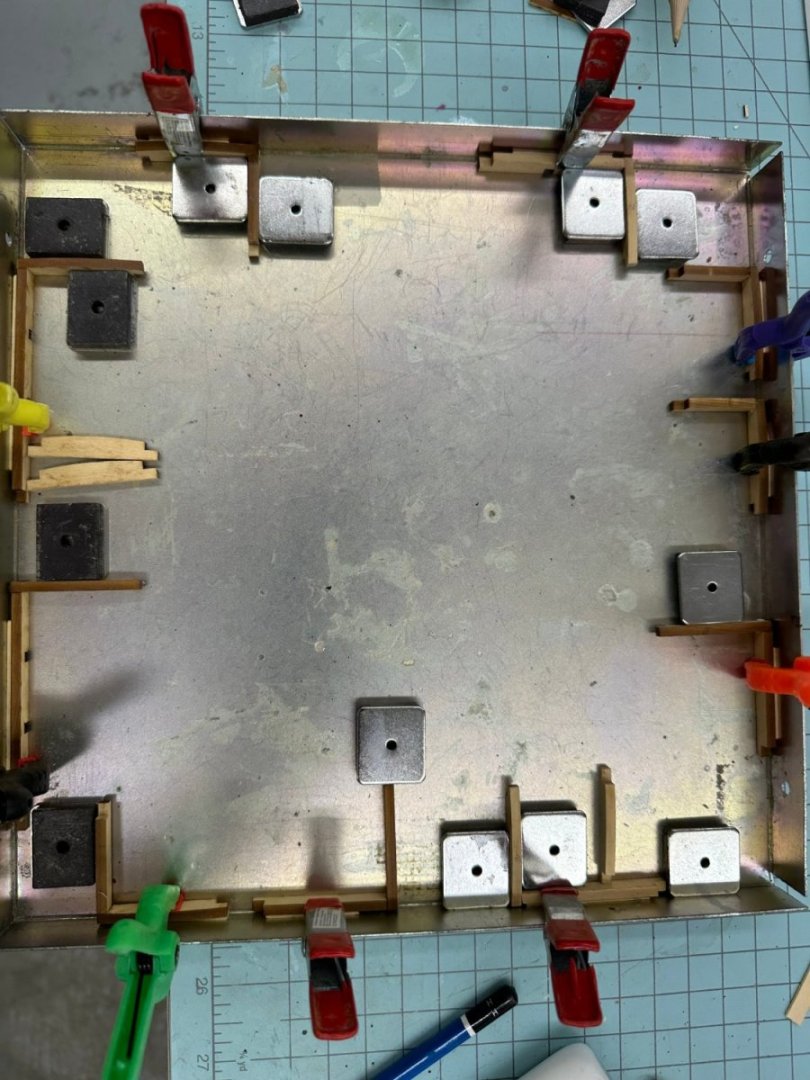
While waiting for paint/glue to dry are started assembling the hatch coamings. Here are all five of the gun deck coamings in various states of assembly. The clamps are holding one coaming piece and a 3/64" strip of scrap to keep the coaming away from the side of the enclosure. The interlocking pieces at the corners extend slightly past even with the adjacent piece and would mess up the alignment if not allowed of fully join at the corner.
- 389 replies
-
- 1
-
-
- winchelsea
- Syren Ship Model Company
- (and 1 more)
-
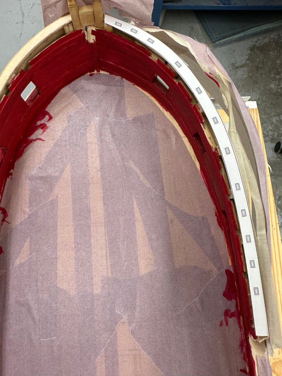
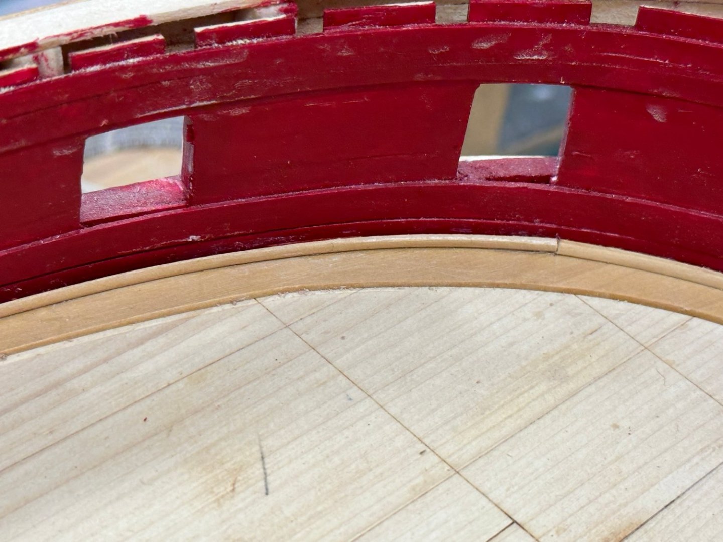
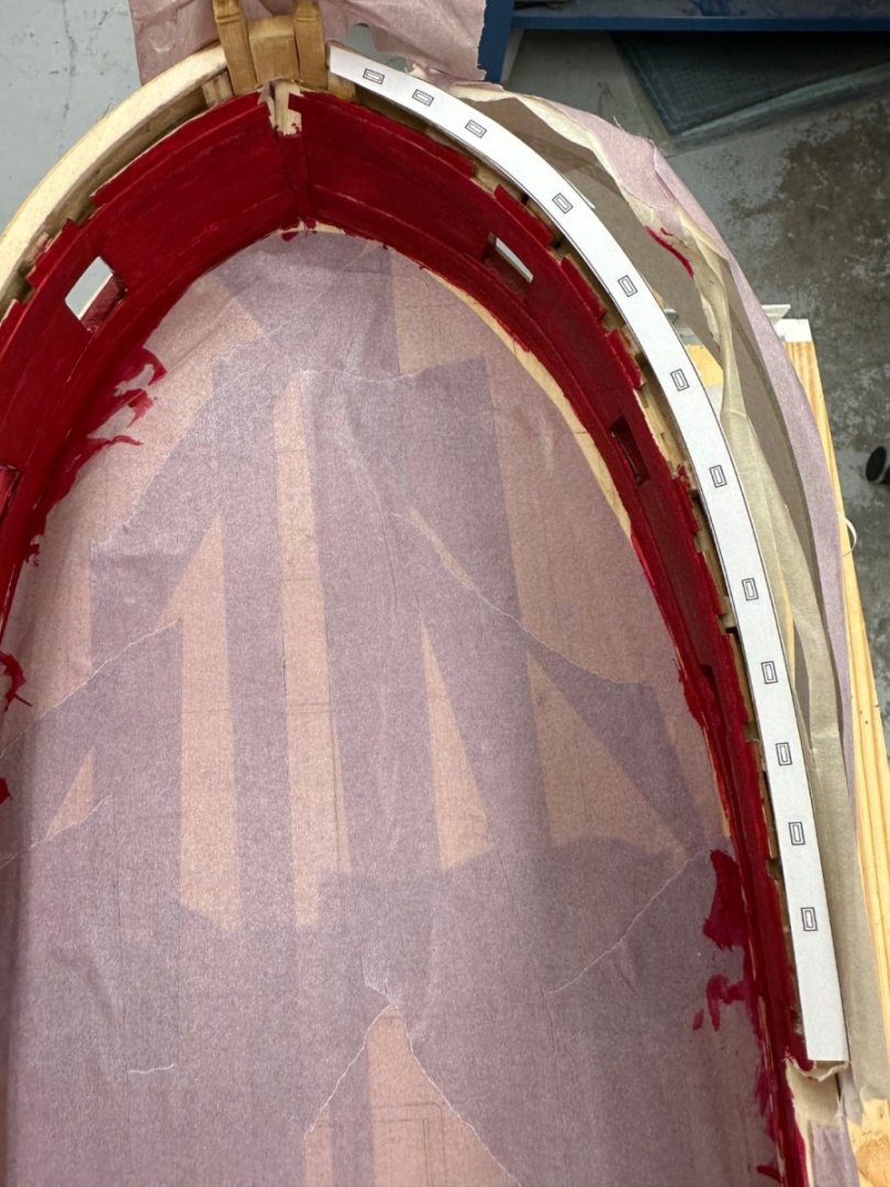
Thanks for the "heads up". I printed out the cap rail from Chapter 9 and cut out the starboard side to make sure the cap rail is going to fit and it looks "pretty good". Hopefully this is what you were referring to. I did add some additional fillers at the bow since the false deck curvature did not match the curvature of my hull. The false deck ended about 1/8" back from the forward end of the hull structure. So my interior bulkheads (and spirketting) are "less vertical" than is probably shown in the plans. I did taper the additional filler to bring the interior planking to the existing cap rail.
- 389 replies
-
- 4
-
-
- winchelsea
- Syren Ship Model Company
- (and 1 more)