HOLIDAY DONATION DRIVE - SUPPORT MSW - DO YOUR PART TO KEEP THIS GREAT FORUM GOING! (Only 13 donations so far - C'mon guys!)
×


cdrusn89
-
Posts
1,915 -
Joined
-
Last visited
Content Type
Profiles
Forums
Gallery
Events
Everything posted by cdrusn89
-
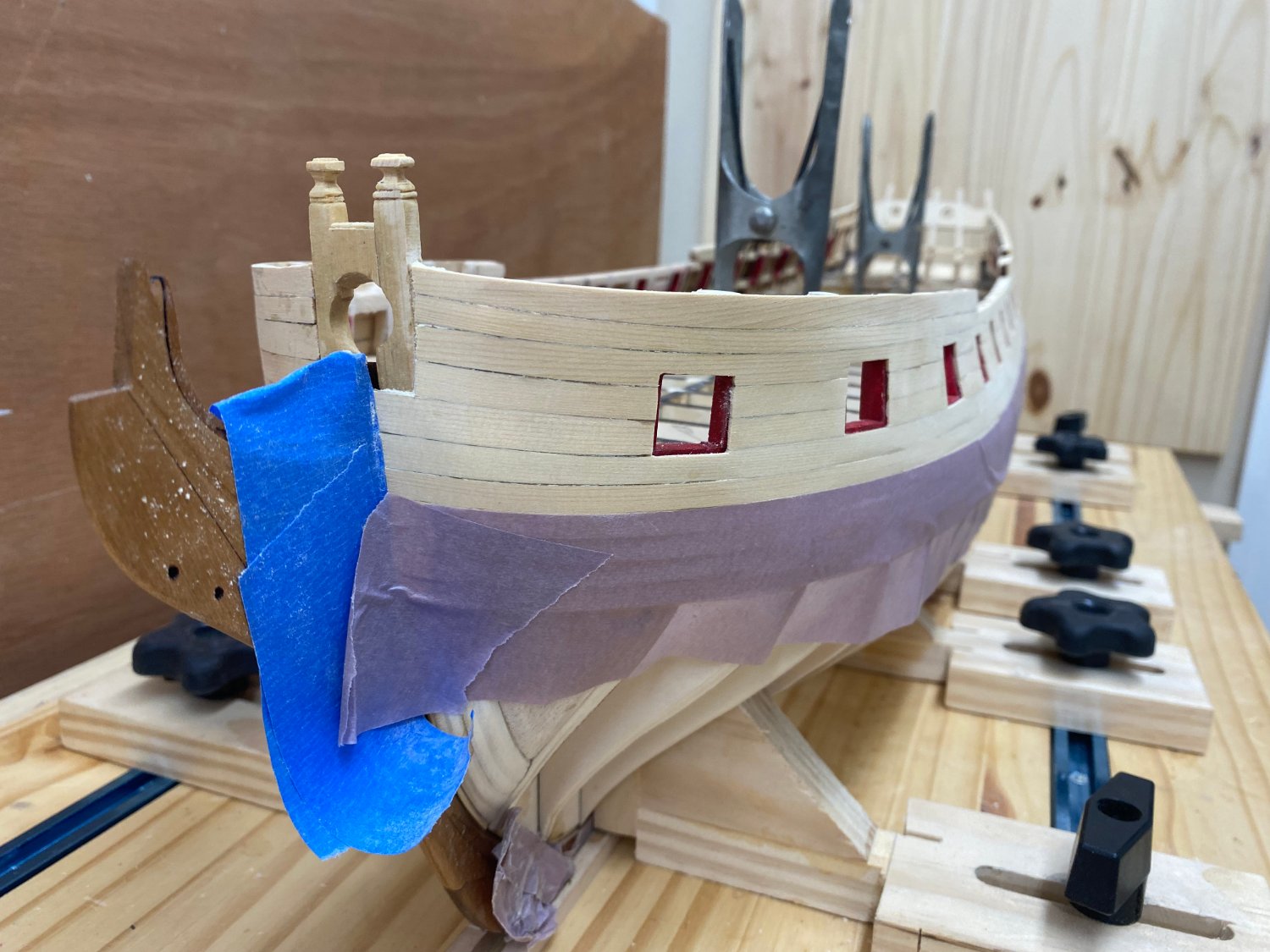
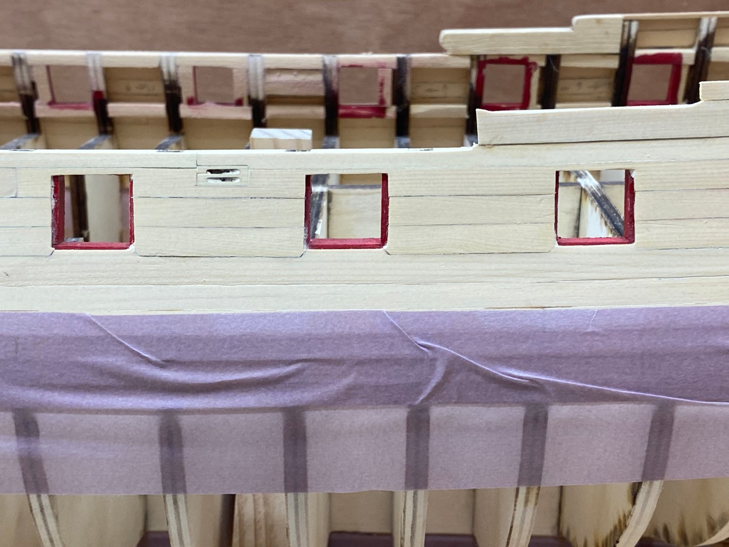
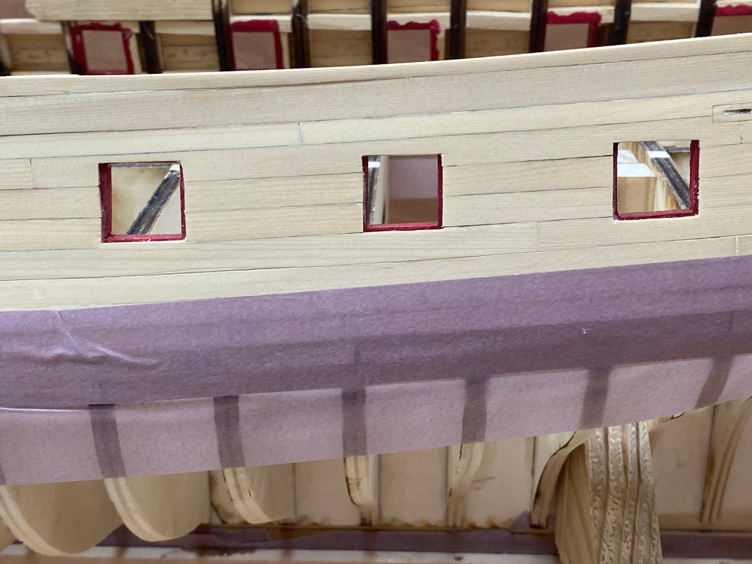
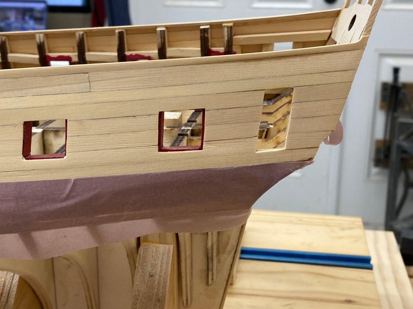
 I got the anchor lining (both pieces) installed, painted and WoPed. On to the port side now (after applying some purple masking tape over the wales on this side.
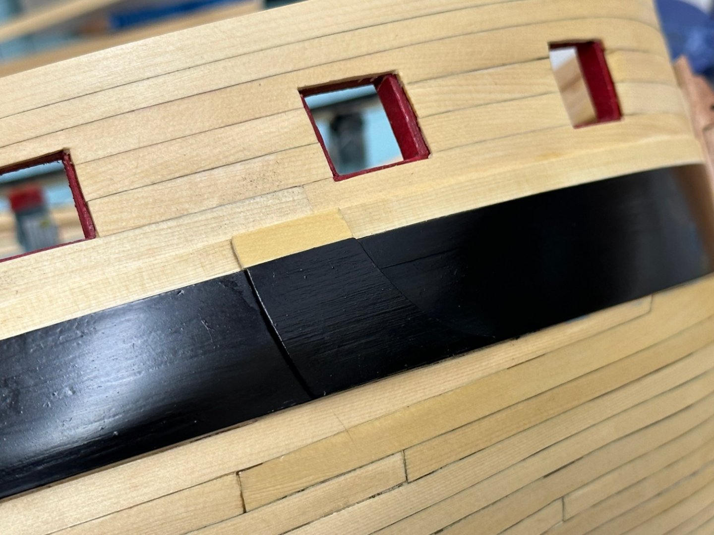
- 389 replies
-
- 5
-

-
- winchelsea
- Syren Ship Model Company
- (and 1 more)
-
Thanks Chuck - now I realize I forgot the anchor lining. Oh well, at least I will (probably) remember it on the port side and install before painting the wales.
- 389 replies
-
- 1
-
-
- winchelsea
- Syren Ship Model Company
- (and 1 more)
-
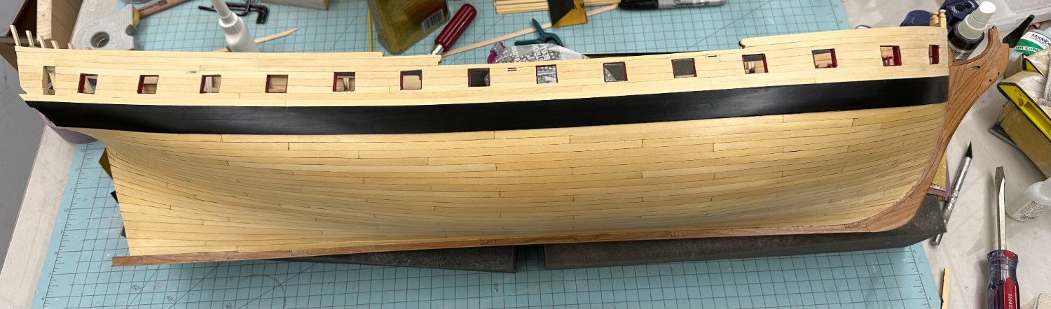
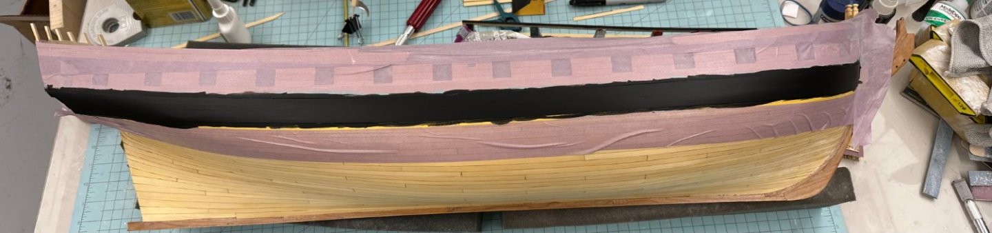
Tape came off - nice clean line at bottom. I added the black strake and am going to give the topsides/black strake one coat of WoP and several coats on the wales before I move to the port side for a "rinse and repeat".

- 389 replies
-
- 10
-
-
- winchelsea
- Syren Ship Model Company
- (and 1 more)
-
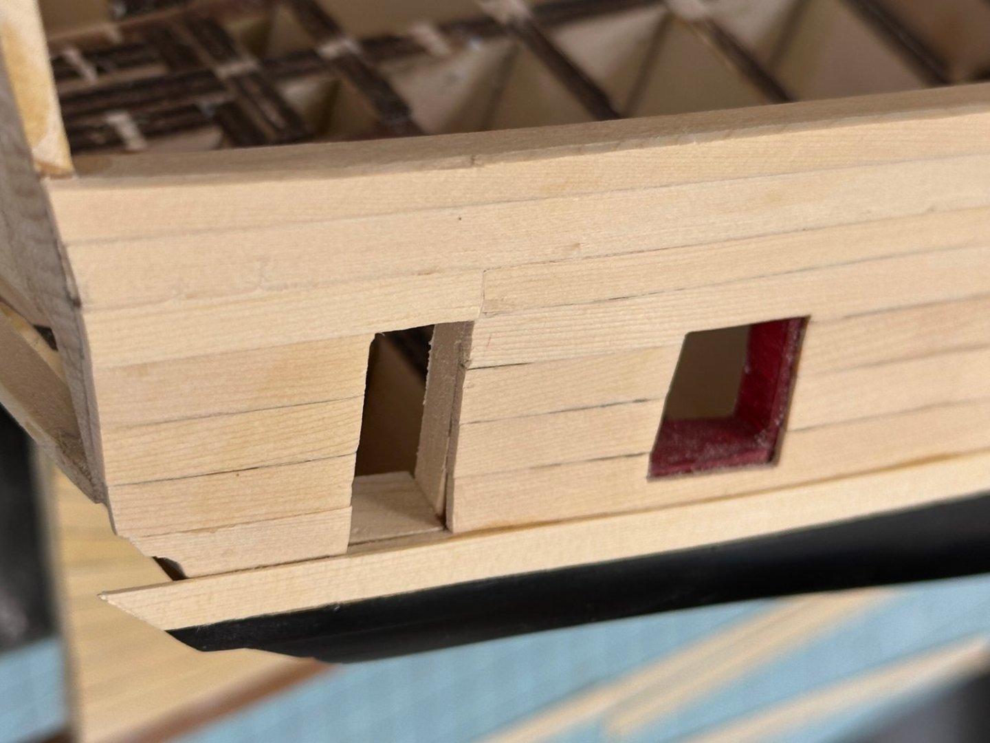
Thanks Chuck Here is the starboard side with the wales painted black - three coats with 600 grit sanding between coats. I'll wait until tomorrow to take off the masking and see what else may need doing before I add the "black" strake which is, of course, not black, at least not on Winnie.
- 389 replies
-
- 5
-
-
- winchelsea
- Syren Ship Model Company
- (and 1 more)
-
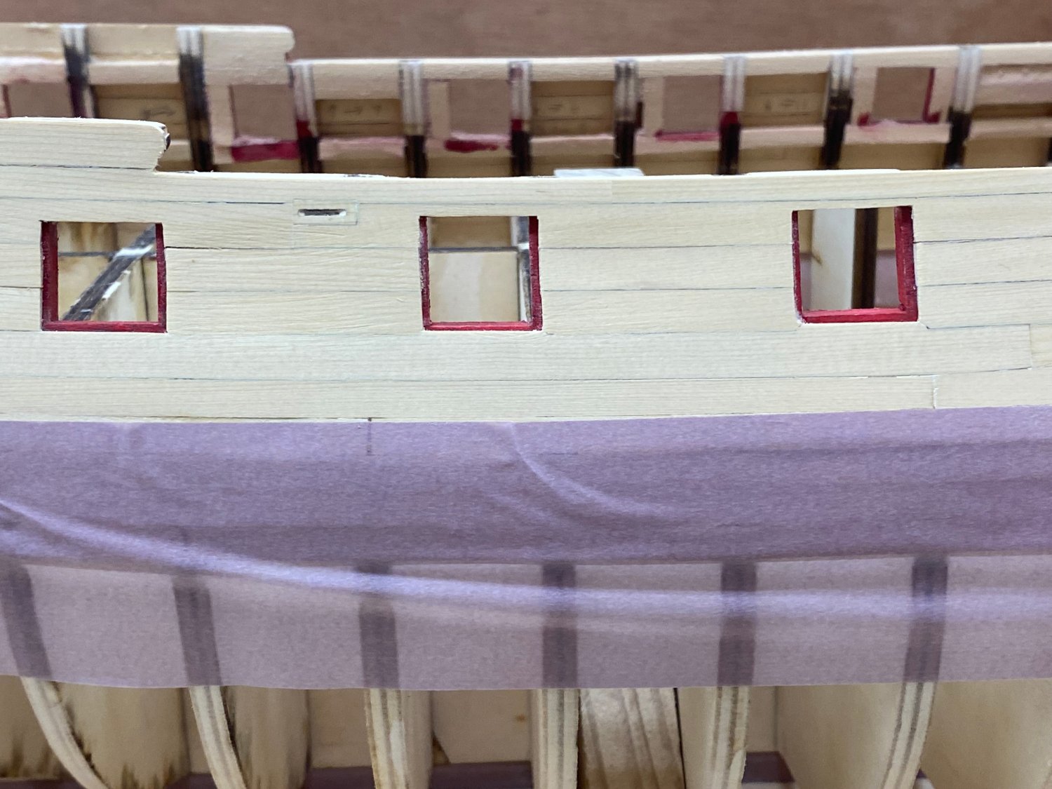
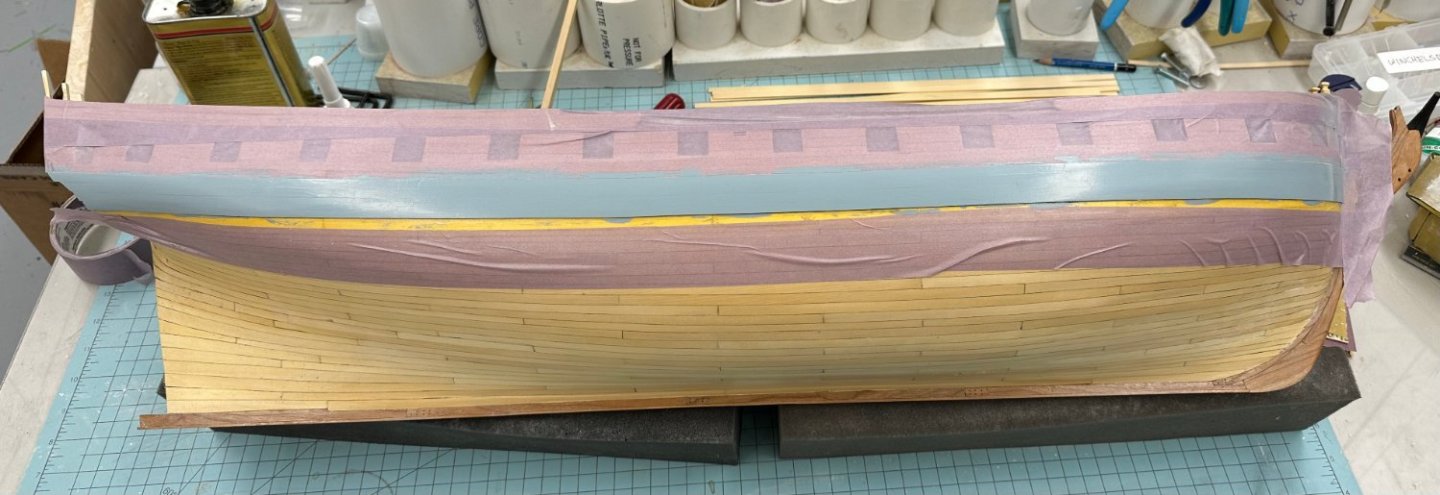
Try as I might (three layers of filler, four coats of primer sanding with 400 grit between coats) I was not able to get all the seams between the planks to "disappear" like they appear to have done in Chuck's monograph. So I "gave up" and this is how the wales look before the first coat of flat black (Badger 16-454 #82 BLACK (1943)). I did completely mask off the bottom edge from the hull planking after proving to myself that I could not keep paint from going over the edge. The four coats of WoP made scraping the gray off pretty easy. I used Tamiya 10mm tape and then sealed the edge at the hull with flat acrylic paint.
- 389 replies
-
- 5
-
-
- winchelsea
- Syren Ship Model Company
- (and 1 more)
-
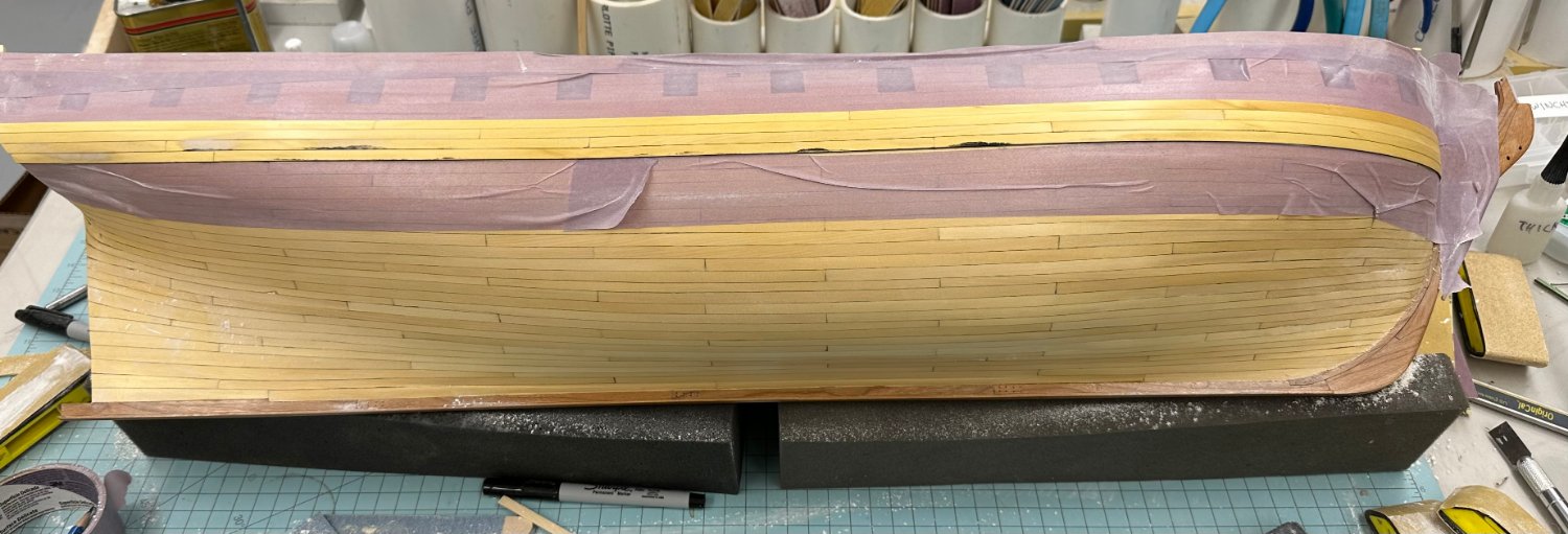
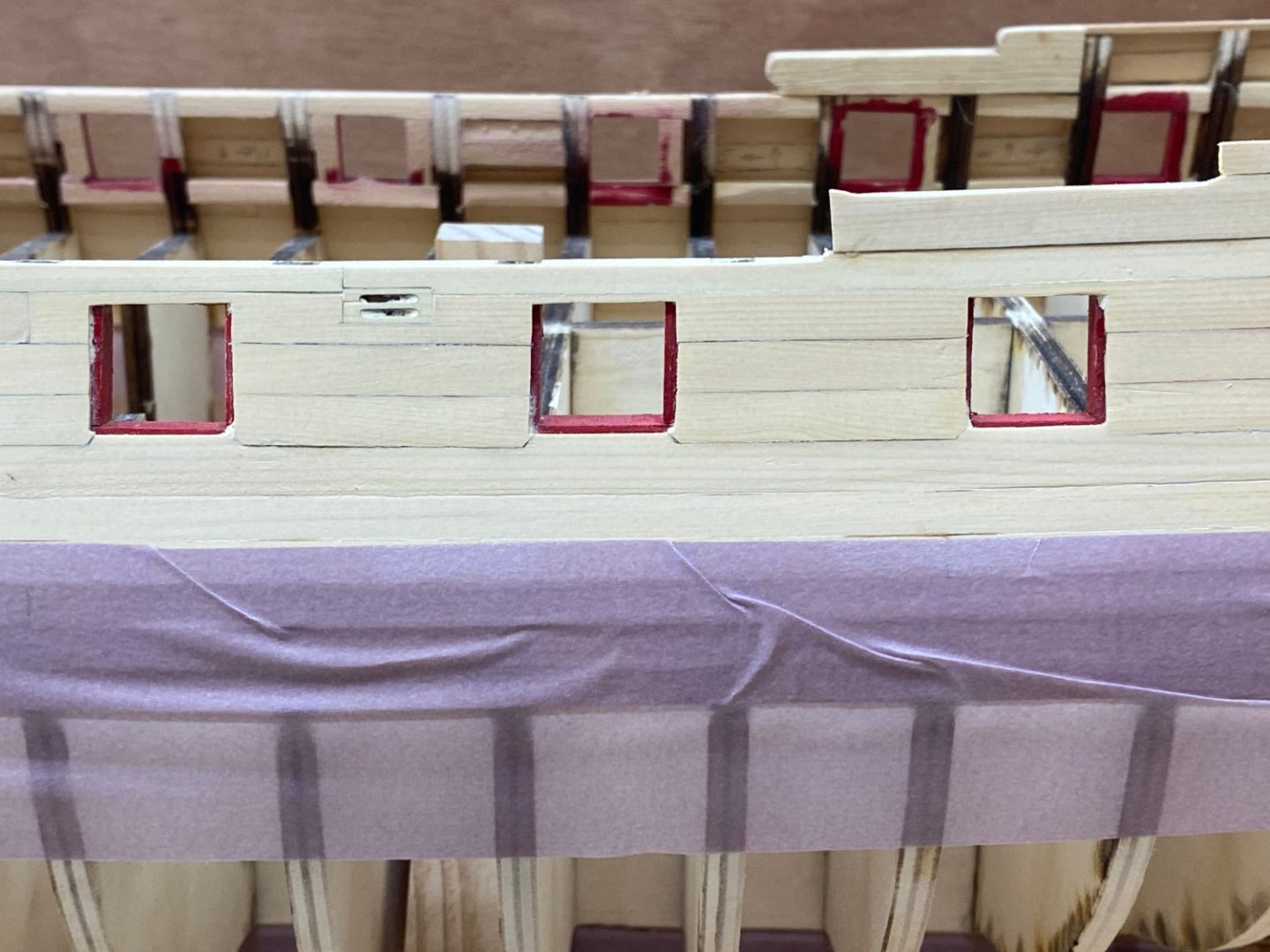
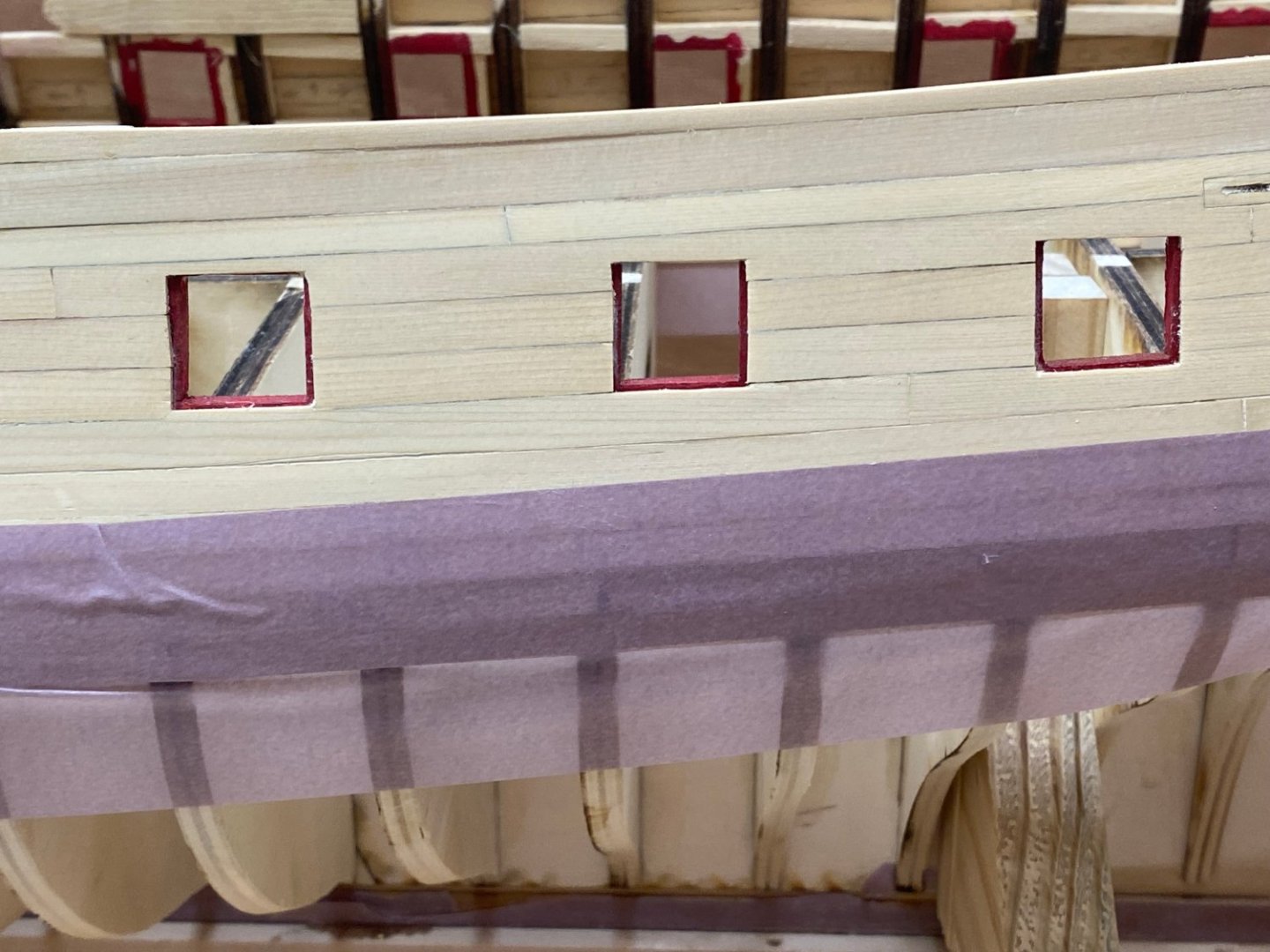
I put four coats of WoP on the hull below the wales hoping to keep errant drops of paint, glue, coffee et al at bay. I will likely cover the lower hull with delicate finish masking tape (the purple stuff) after I get the second layer of [planking on the wales. Speaking of the second layer, I have it on the starboard side and am preparing to finish sand it and get it covered with the flat black paint. I decided to paint the lower edge of the lowest row black before I installed it to avoid having to paint the lower edge afterwards. That is some of the black that is in the picture. The black not on the lowest row is me picking the wrong piece and not realizing it until it was too late. I have applied and mostly sanded off one application of filler. I will do another when the thinner which is on the wales now evaporates. After the next round of filler I am going to try a primer coats and see how that looks before committing to black.

- 389 replies
-
- 6
-
-
- winchelsea
- Syren Ship Model Company
- (and 1 more)
-
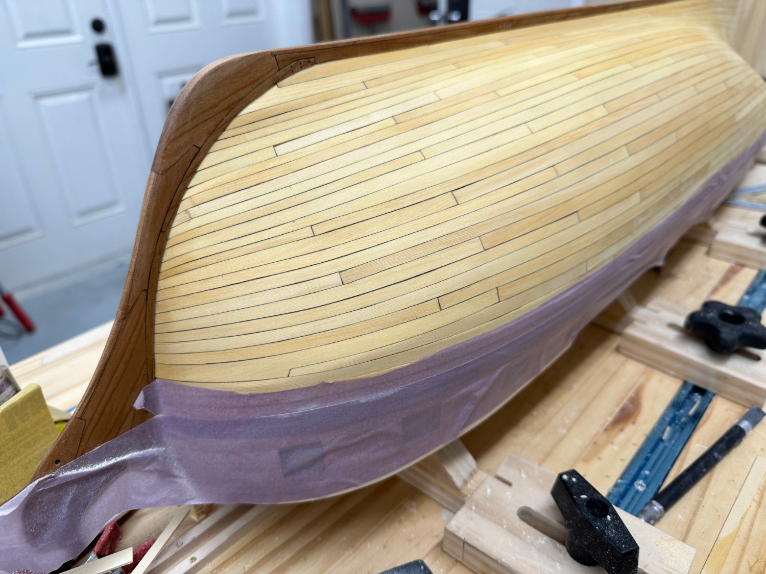
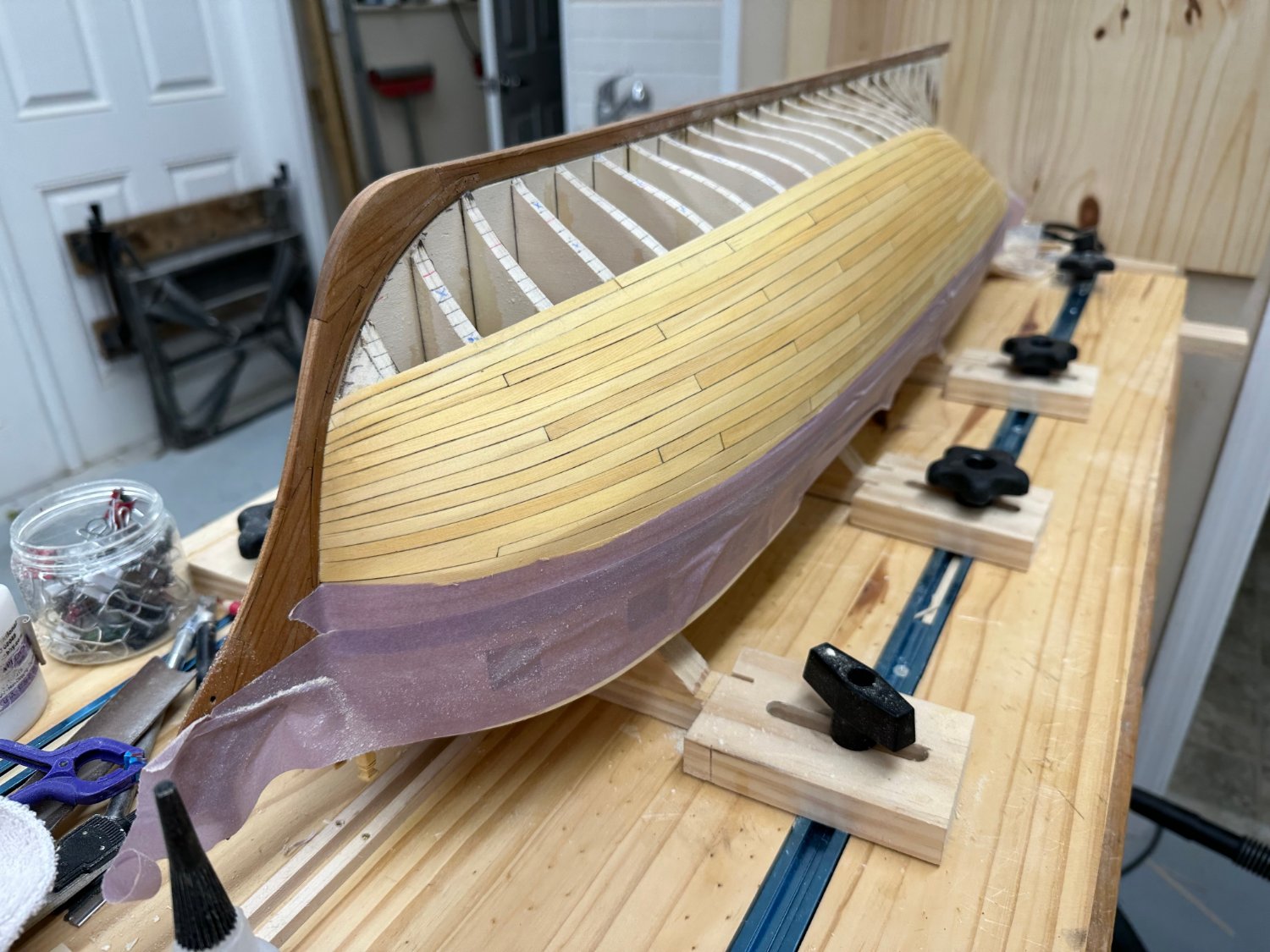
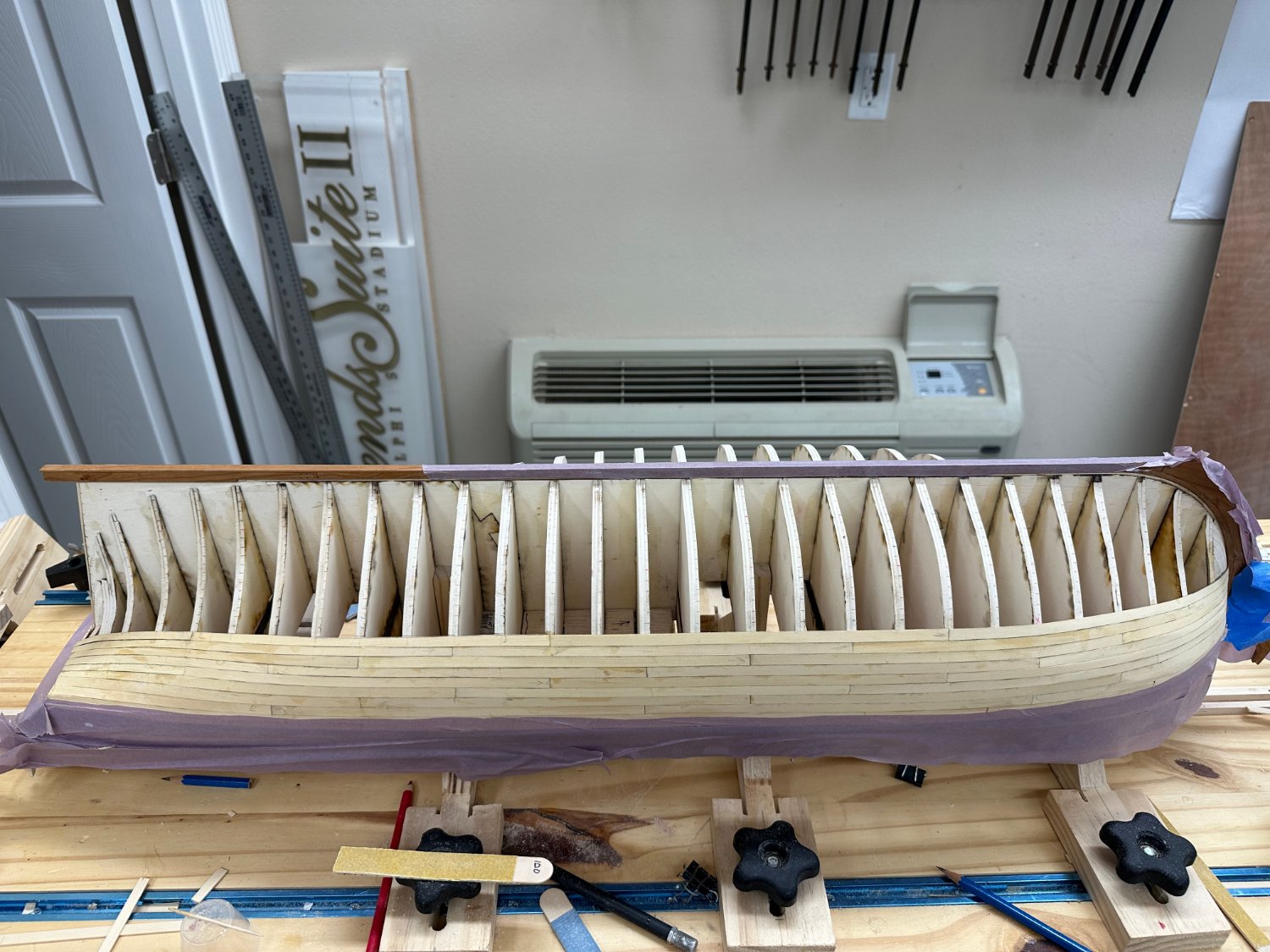
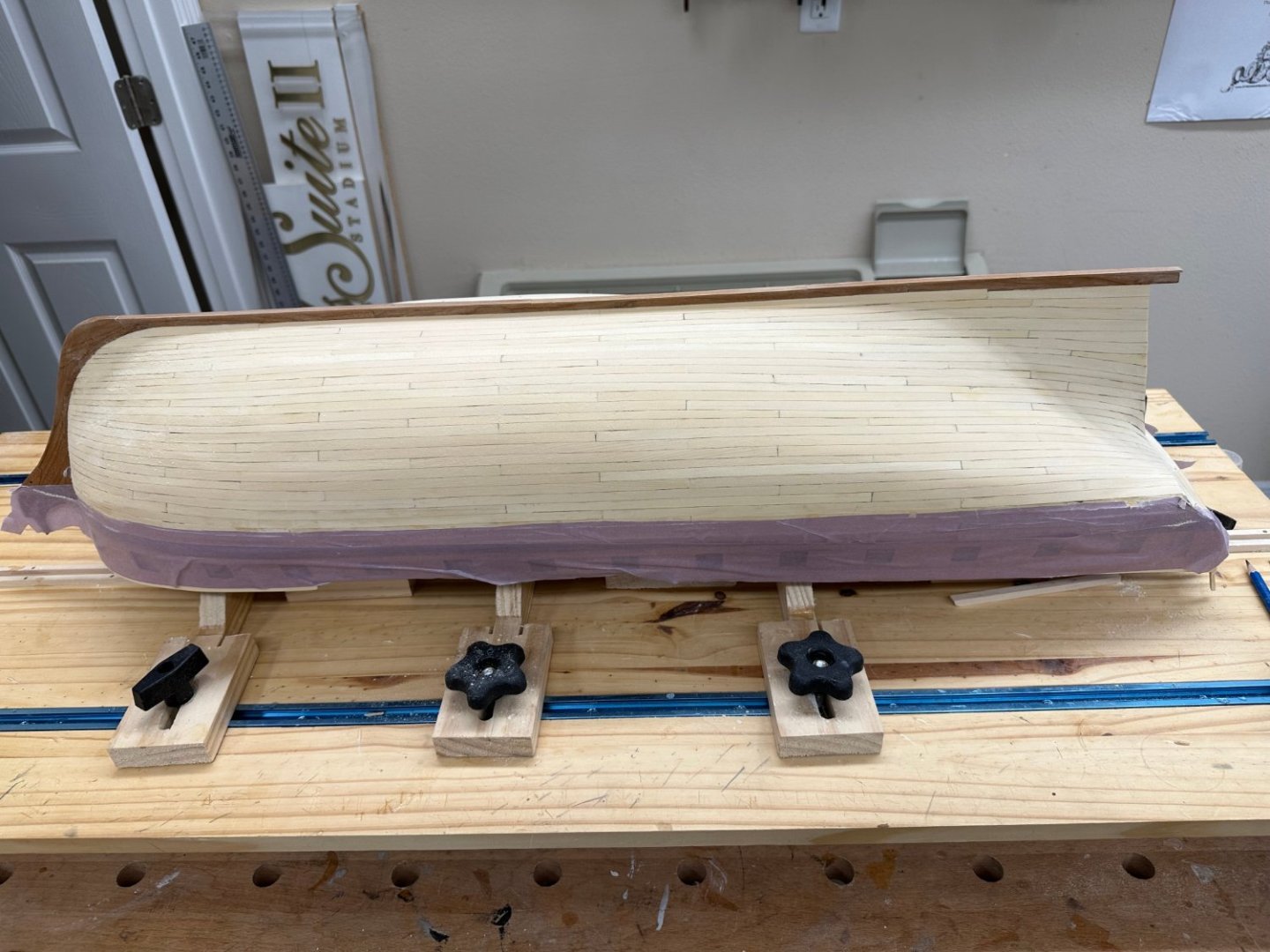
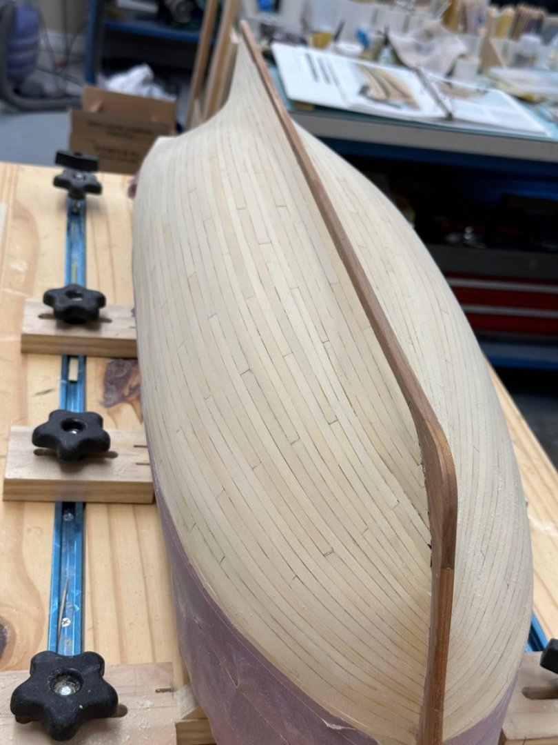
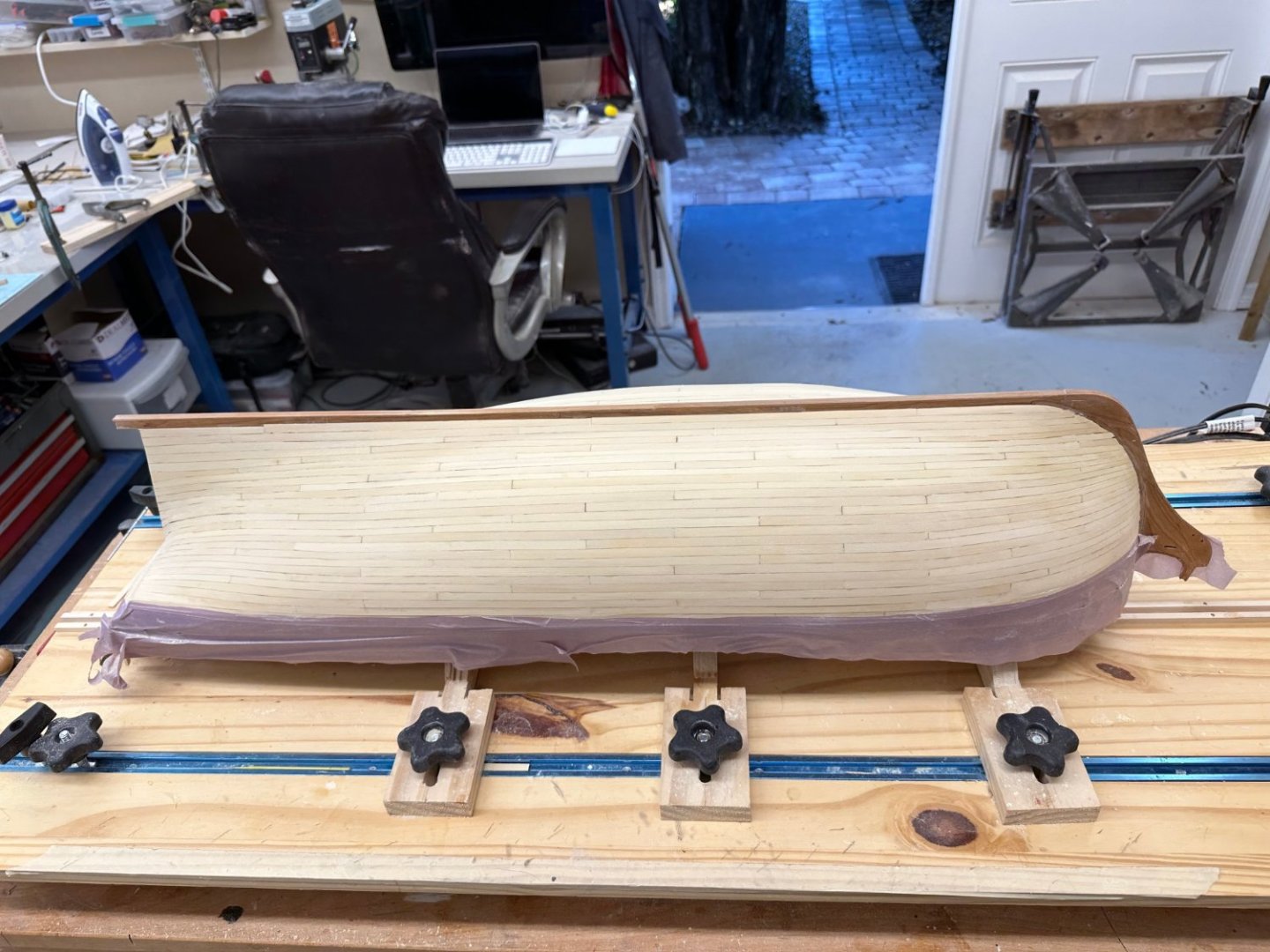
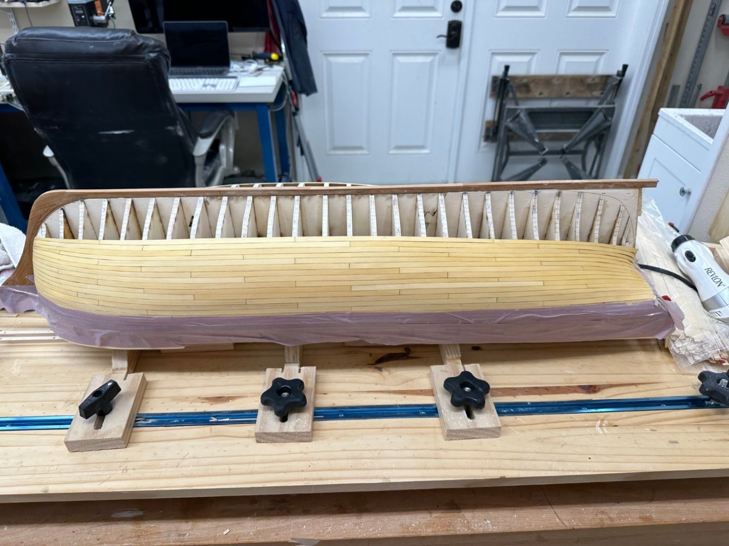
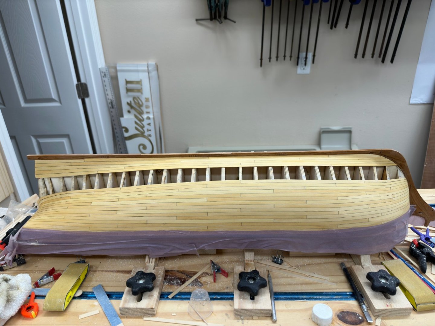
Planking completed on both sides, stern trimmed for stern post installation.Now for a final pass with 150 grit paper, then 220, then 320 and then the WoP. I intentionally did not add the extra layer of planking on the wales before so after the stern post installation adding them wand painting them will be next before moving on to Chapter 3 and all the fun of the quarter galleries.
- 389 replies
-
- 8
-
-
- winchelsea
- Syren Ship Model Company
- (and 1 more)
-
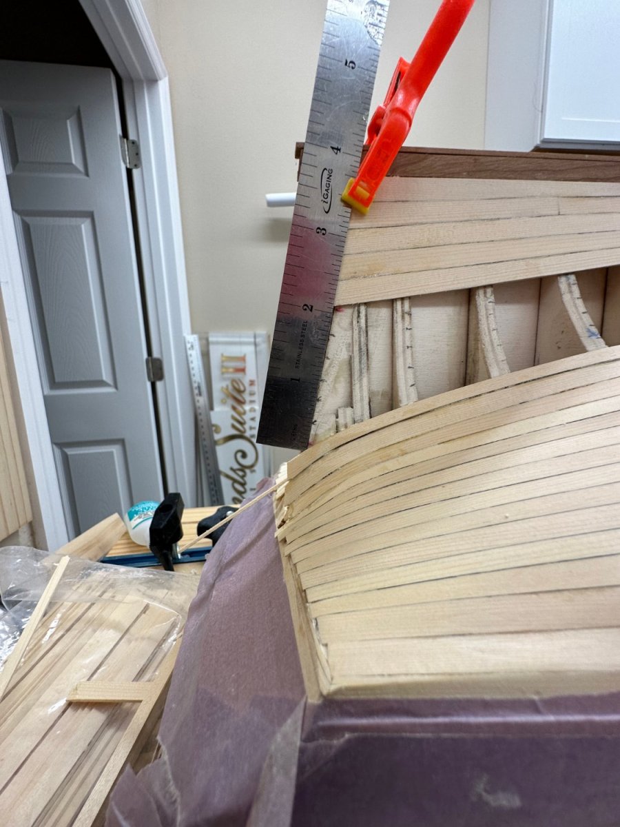
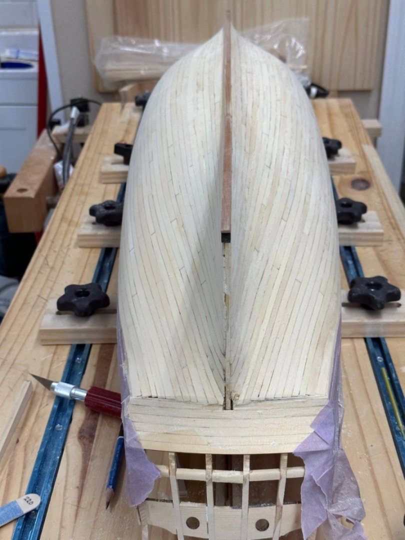
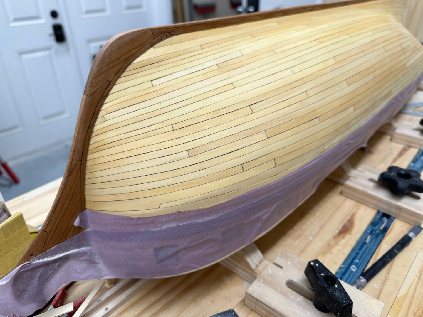
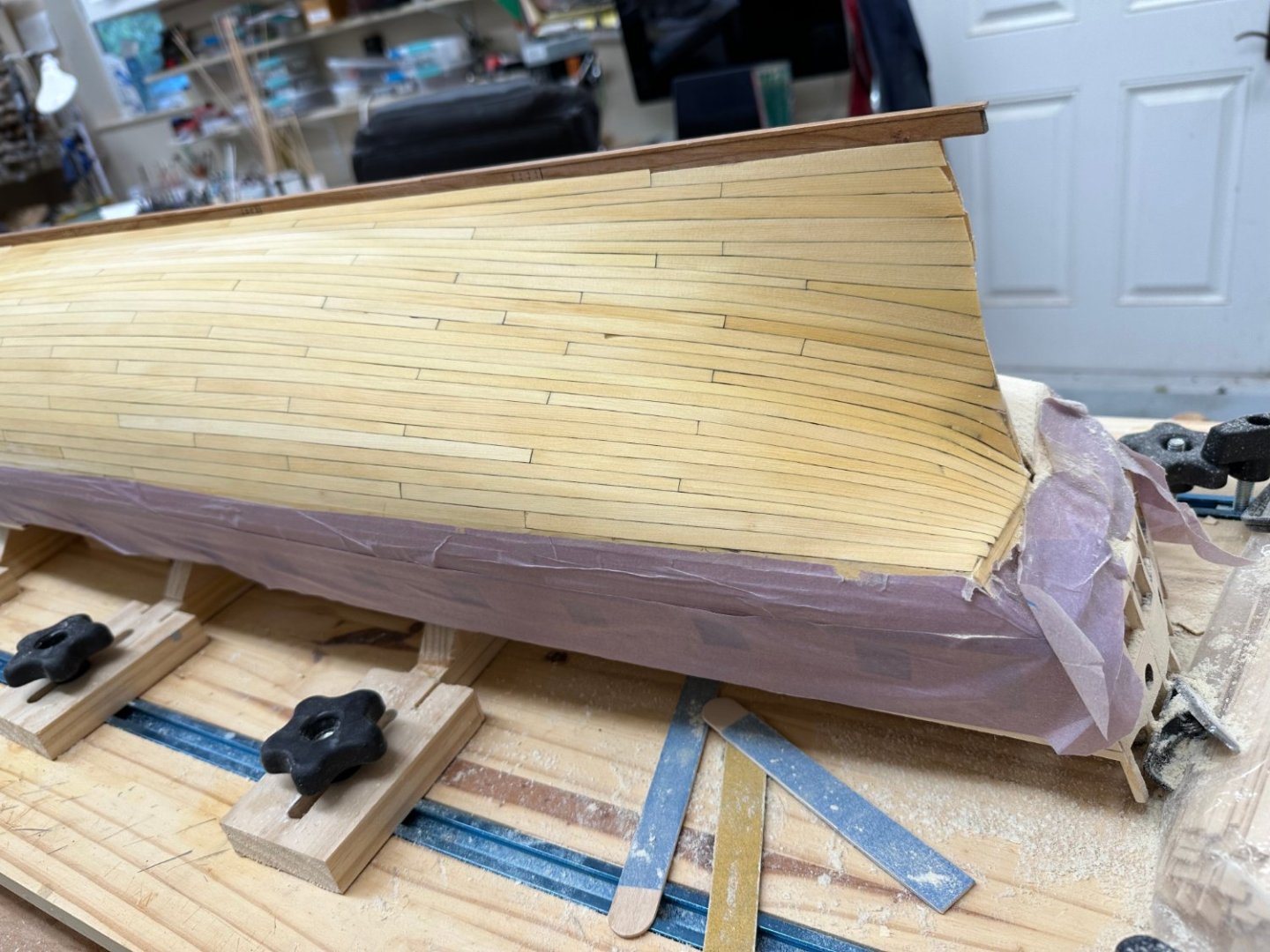
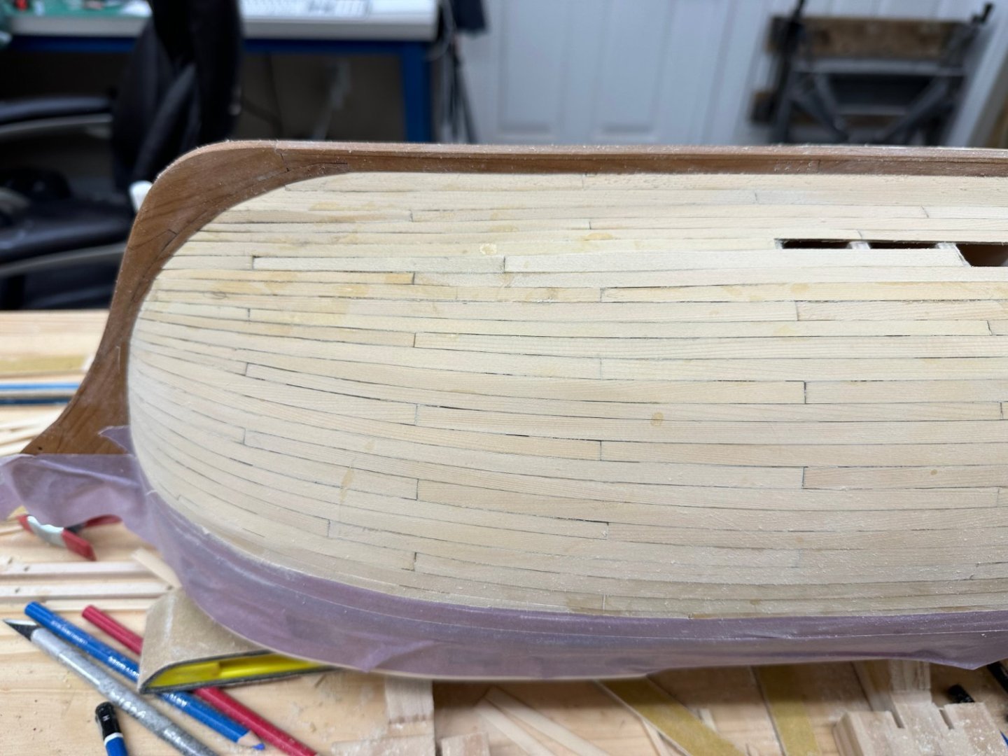
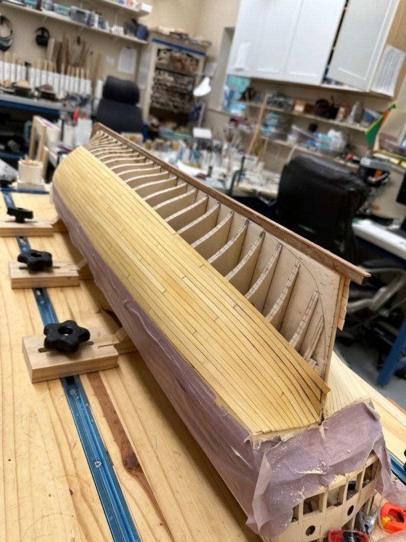
Starboard side planking completed. Issues arose overnight. At the bow two of the planks cracked just aft of the bow. You can see them in the second photo. There were already several planks on each side of them by the time I noticed this morning so I am going to have to live with it. I did not notice them as I was installing them but they probably cracked then but I suppose it is possible they cracked overnight as the shop cooled down or stress from the other planks built up? There also a "nick" in one of the planks near the stern - not sure how that happened either. Now back to the port side.

- 389 replies
-
- 6
-
-
- winchelsea
- Syren Ship Model Company
- (and 1 more)
-
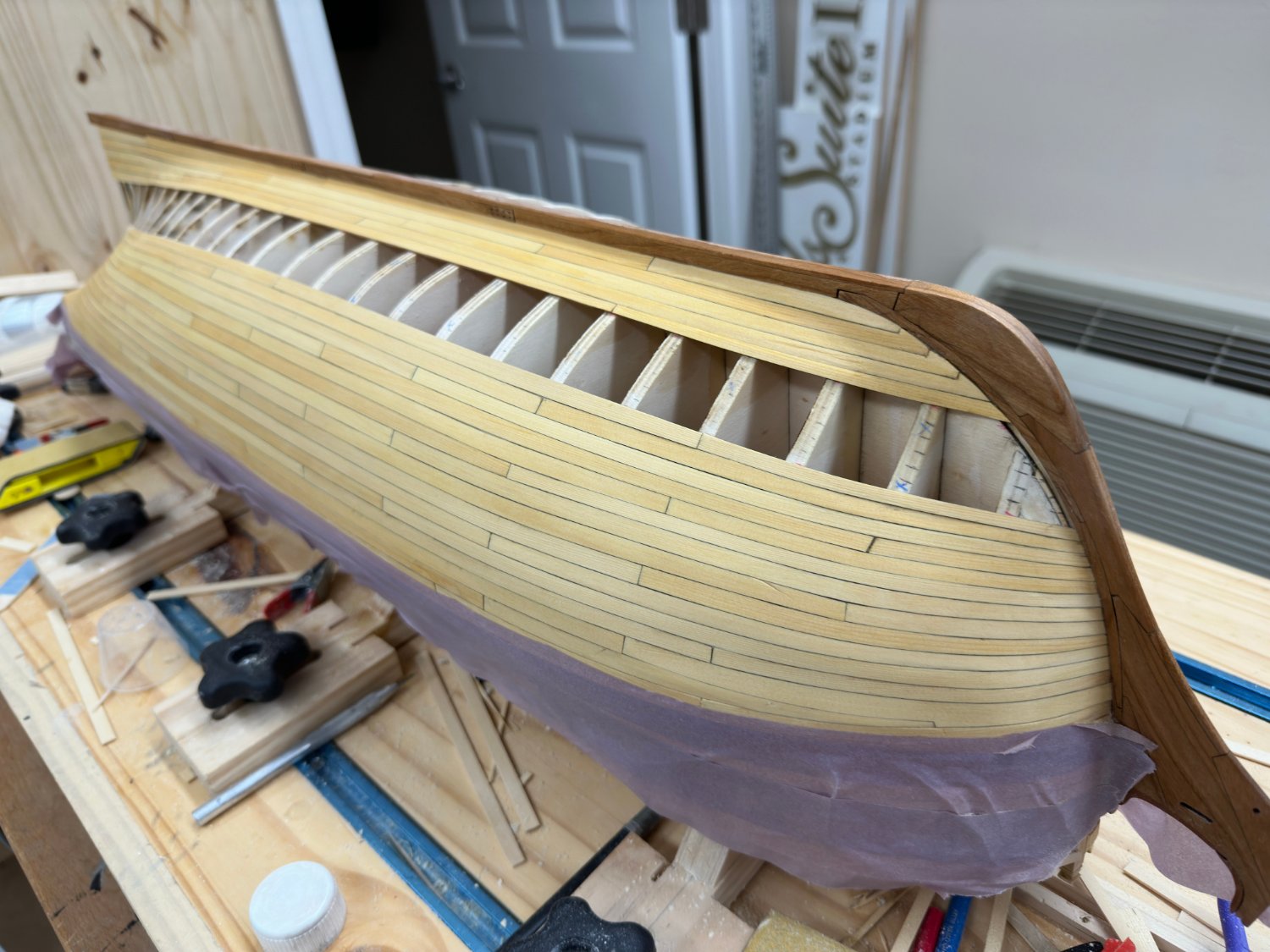
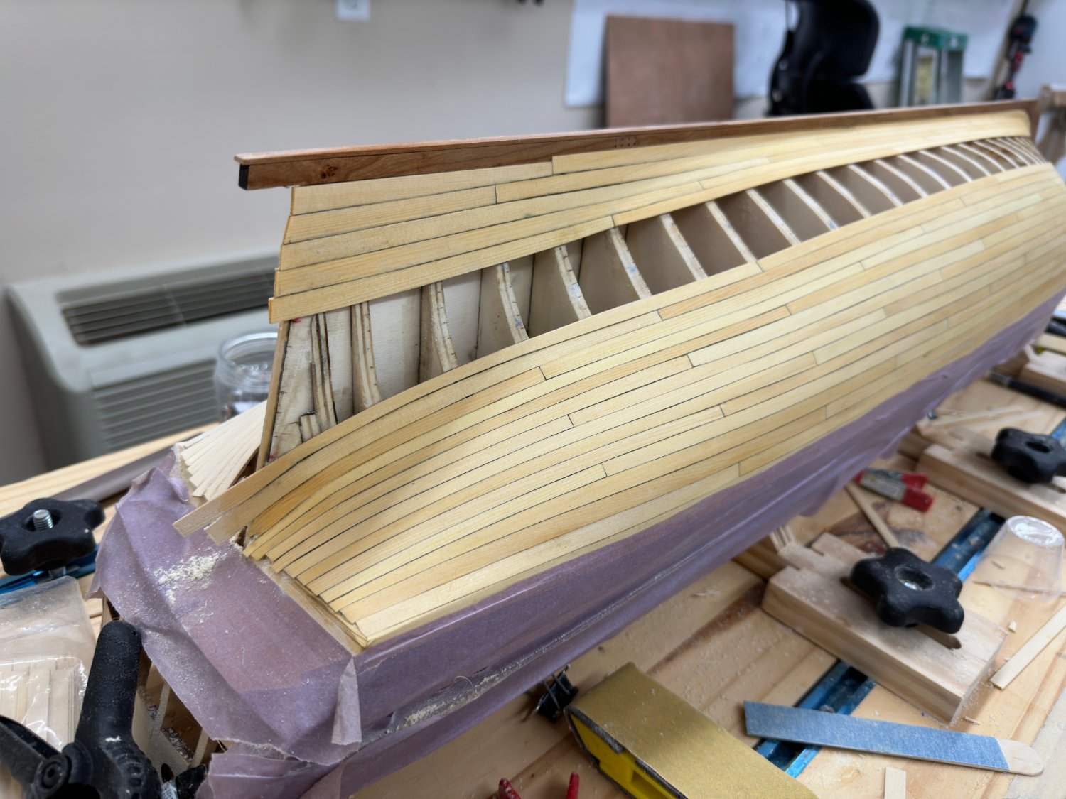
Thanks guys for the "Likes". I got the upper band on the starboard side completed and then just "kept going". Starboard side forward planking completed. I On the final plank I added an extra joint - I tried three times to make a piece that would fit across the standard eight bulkheads but finally decided to split that plank into two pieces. I only had to make the two pieces once each. It looks pretty obvious in the picture - hopefully it will not stick out too much after sanding and WoP. I hope to complete the starboard side tomorrow.
- 389 replies
-
- 4
-
-
- winchelsea
- Syren Ship Model Company
- (and 1 more)
-
Starboard side bands one and two completed. Preliminary sanding and thinner applied. Five of eight bands finished. Now for band 4 on this side.

- 389 replies
-
- 8
-
-
- winchelsea
- Syren Ship Model Company
- (and 1 more)
-
Glenn, I know I should not need stealers but the math does not work out - 6 planks 5/16" wide would be 30 16ths, the space to be covered is 2 1/16" = 33 16ths. The plan is to add a 5/16" plank to the top and bottom and remeasure. If there is still an issue add a 3/8" plank (suitably tapered going forward) and see where that leaves me. I judged the monograph counter planking scheme as beyond my limited capabilities and will "live" with a somewhat modified "look" at the counter.

- 389 replies
-
- 3
-
-
- winchelsea
- Syren Ship Model Company
- (and 1 more)
-
I decided to do the garboard band on the port side before moving over to the starboard side. I am a little concerned about the stern. Measured at the stern post I have 2 1/8" to cover but at the bulkhead 29 it is 1 5/8". 2 1/8" is more than can be covered by 6 5/16" wide planks. So I need at least one 3/8" plank (probably two). Narrowing down to 1 5/8" in less a 3/4" inch (on average, it is 1 inch at the bottom (top) and 1/2" at the top (bottom). Might make for some pretty strange looking planks. Might be time for a stealer. But before that I will see what I can come up with for a 3/8" wide plank. I have time, need to get the starboard side in the same shape as the port side.


- 389 replies
-
- 5
-
-
- winchelsea
- Syren Ship Model Company
- (and 1 more)
-
Band two completed on the port side. I have done some preliminary sanding and a wipe down with thinner. Looks like I could have done a better job getting the planks a more uniform color. I am tempted to start the garboard band now before doing band two on the starboard side. Beginning to look like a ship's hull.


- 389 replies
-
- 6
-
-
- winchelsea
- Syren Ship Model Company
- (and 1 more)
-
Starboard side upper belt complete. Back to port side for belt #2.

- 389 replies
-
- 6
-
-
- winchelsea
- Syren Ship Model Company
- (and 1 more)
-
Thanks Chuck. I got the starboard side lined off thanks to the provided templates. Had to make a few minor corrections as would be expected. Now on to more planking.
- 389 replies
-
- 4
-
-
- winchelsea
- Syren Ship Model Company
- (and 1 more)
-
Port side upper belt completed. Working on starboard side (once I get the starboard side lined off).


- 389 replies
-
- 4
-
-
- winchelsea
- Syren Ship Model Company
- (and 1 more)
-
Belt 1 completed at the bow. The yellow coloring is paint thinner - trying to see approximately what the planking will look like after several coats of WoP. Working my way aft now. Then I will work on belt one on the other side before starting belt 2.
- 389 replies
-
- 2
-
-
- winchelsea
- Syren Ship Model Company
- (and 1 more)
-
Today's contribution. The forward portion of the first four planks in the upper belt complete. Plan to add the last two planks in the upper belt at the bow before moving any further aft.

- 389 replies
-
- 4
-
-
- winchelsea
- Syren Ship Model Company
- (and 1 more)
-
The forward portion of the first three rows of the upper belt. The ends of these start the pattern for the butt ends. I have arbitrarily decided on plank lengths of eight bulkheads ~ 9" more or less making the planks 36' long (give or take). These three took most of this afternoon including the three that I messed up and had to "do over". Hopefully no more hurricane clean up to keep me from "pressing on".
- 389 replies
-
- 5
-
-
- winchelsea
- Syren Ship Model Company
- (and 1 more)
-
It has been two hurricanes (Ian and Nicole) and two cruises (Bermuda and Med/TransAtlantic) since I last did any work on Winnie. So here goes, planking the lower hull starts NOW!
- 389 replies
-
- 3
-
-
- winchelsea
- Syren Ship Model Company
- (and 1 more)
-
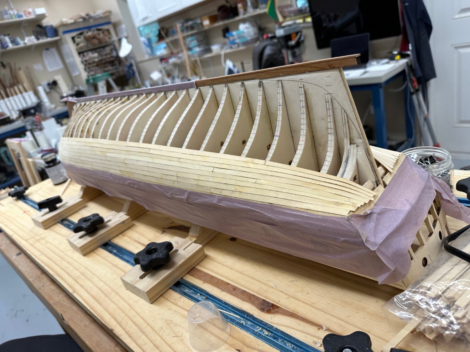
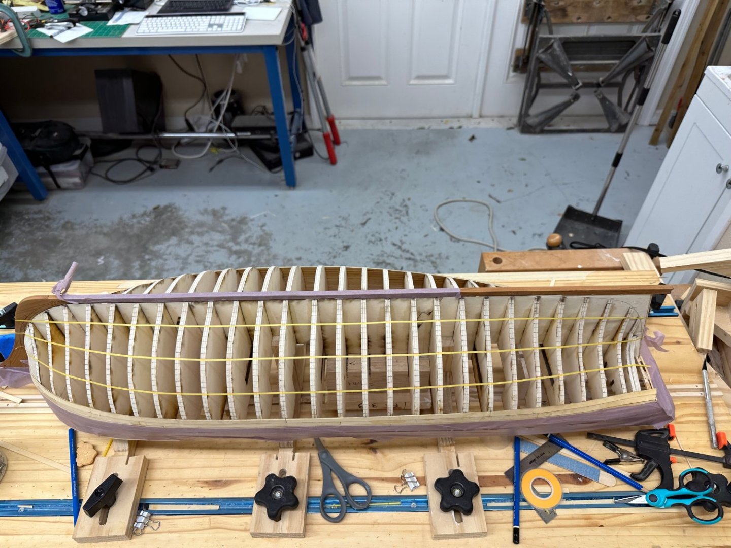
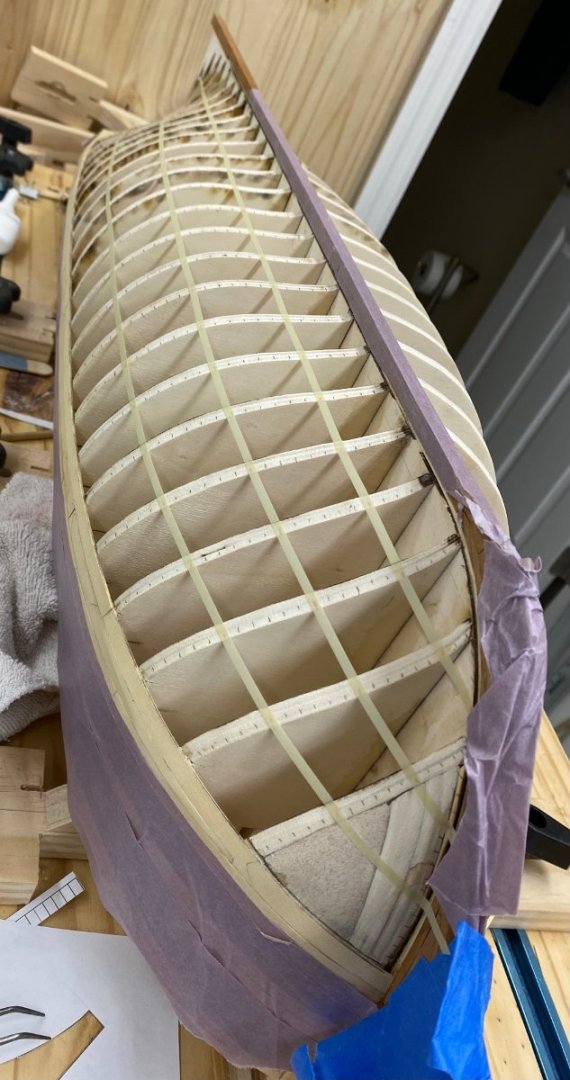
I got all the tic strips transferred to the bulkheads and ran some masking tape down the marks that define the four belts. I had to use 1/8" tape as the striping tape I had does not have enough "stick" to grab the bulkheads and stay. I guess it was designed for a continuous surface (or it is really old, another possibility). That said I had to be very careful to get the tic mark in the center of the tape, or at least in the same place every time. I finally decided to put the lower edge of the tape on the tic mark. I found two areas where there seemed to be too sharp a "bend" so now I should tape up the rest of the tic marks but I do not have enough tape to do that. More is on the way and I leave Sunday for two weeks so "fixing" the tic marks will have to wait until I return. I'll work on the two rows of planking on the port side tomorrow to keep from having to listen to the "packing frenzy" in the house. Anyway here is the starboard side with the belts "outlined.
- 389 replies
-
- 6
-
-
- winchelsea
- Syren Ship Model Company
- (and 1 more)
-
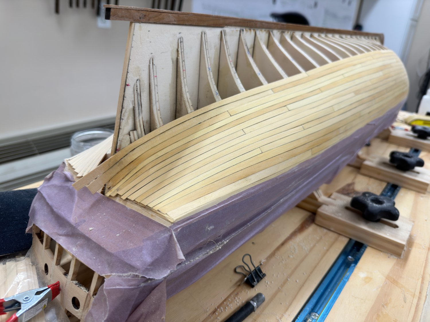
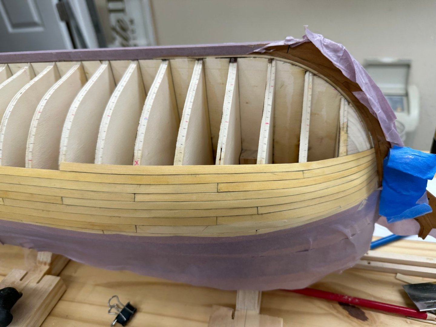
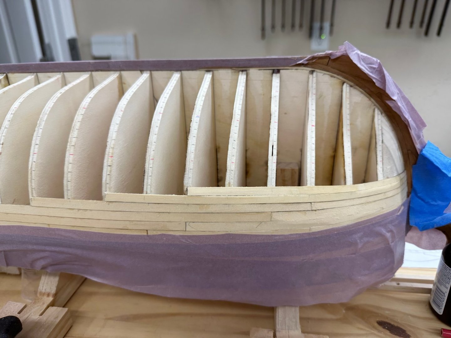
I completed the first two rows of planks below the wales on the starboard side. I had to modify the provided drop plank some (sanded off some of the shorter side so the longer piec e would hit the mark at the 1/2" mark on bulkhead Q). I took several trees (3 if I remember correctly) to get a piece that fit in the "slot" satisfactorily. I curt that piece to extend two bulkheads past the drop plank and then carried that pattern aft until the "end". Here is what they look like. I did some sanding at the bow trying to get some of the protruding edges smoothed out but no sanding or cleanup elsewhere. With that completed I started to line off the starboard side using the provided tic strips. The strips are attached with rubber glue so getting them off is not a big issue. Since the tic strips end short of the rabbit there are 22 planks in the strips so the 23rd plank is the gar-board plank. Six done, 18 to go plus the stem and stern post. No one said this was fast, just much faster than doing it from scratch 😀


- 389 replies
-
- 2
-
-
- winchelsea
- Syren Ship Model Company
- (and 1 more)
-
Chuck, Are there laser cut pieces for the cap rail at the bow or is that just a heat and bend job?
- 1,784 replies
-
- 1
-
-
- winchelsea
- Syren Ship Model Company
- (and 1 more)
-
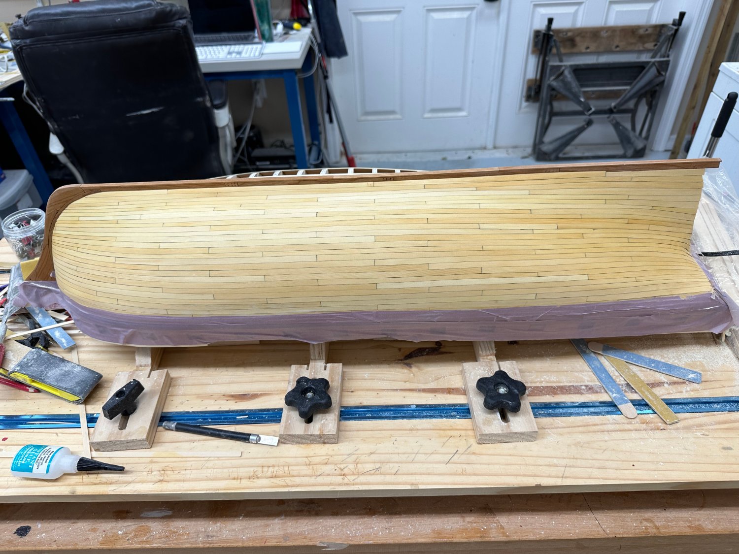
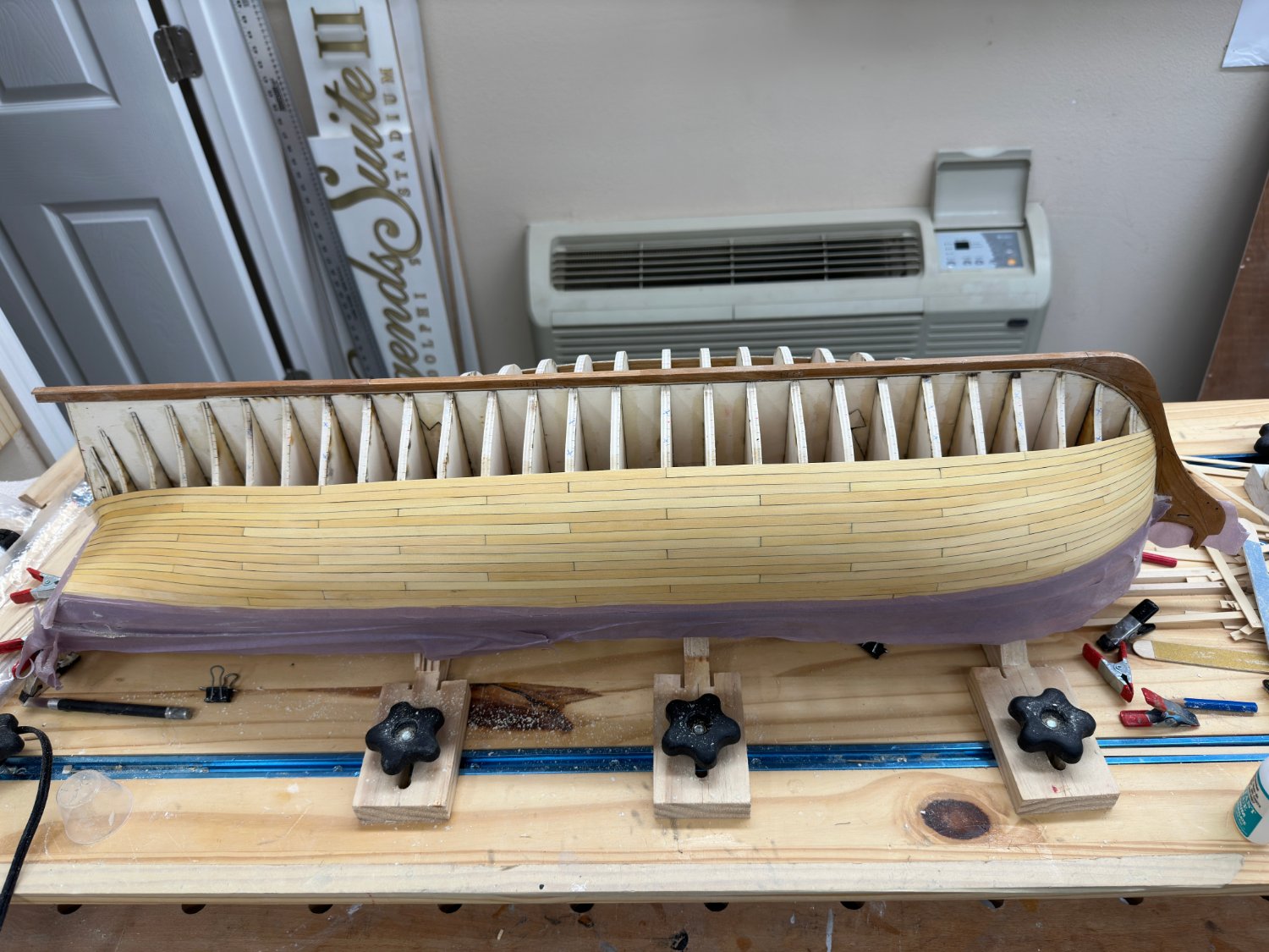
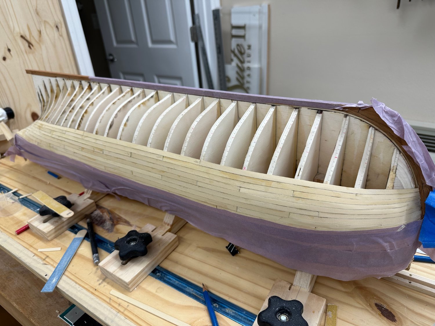
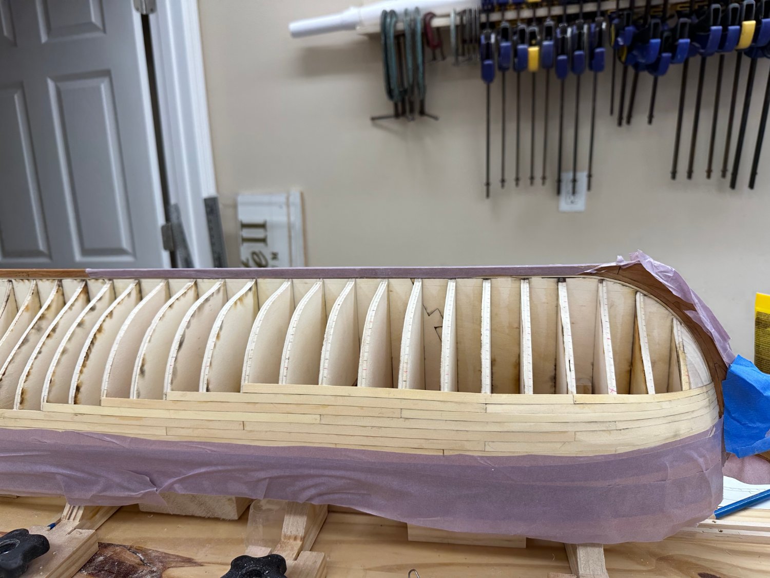
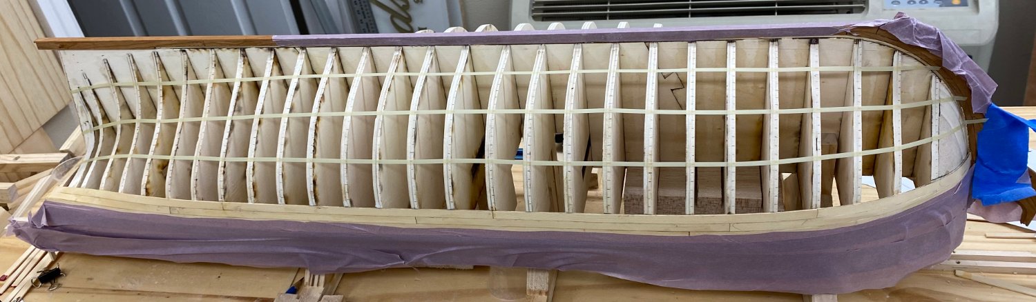
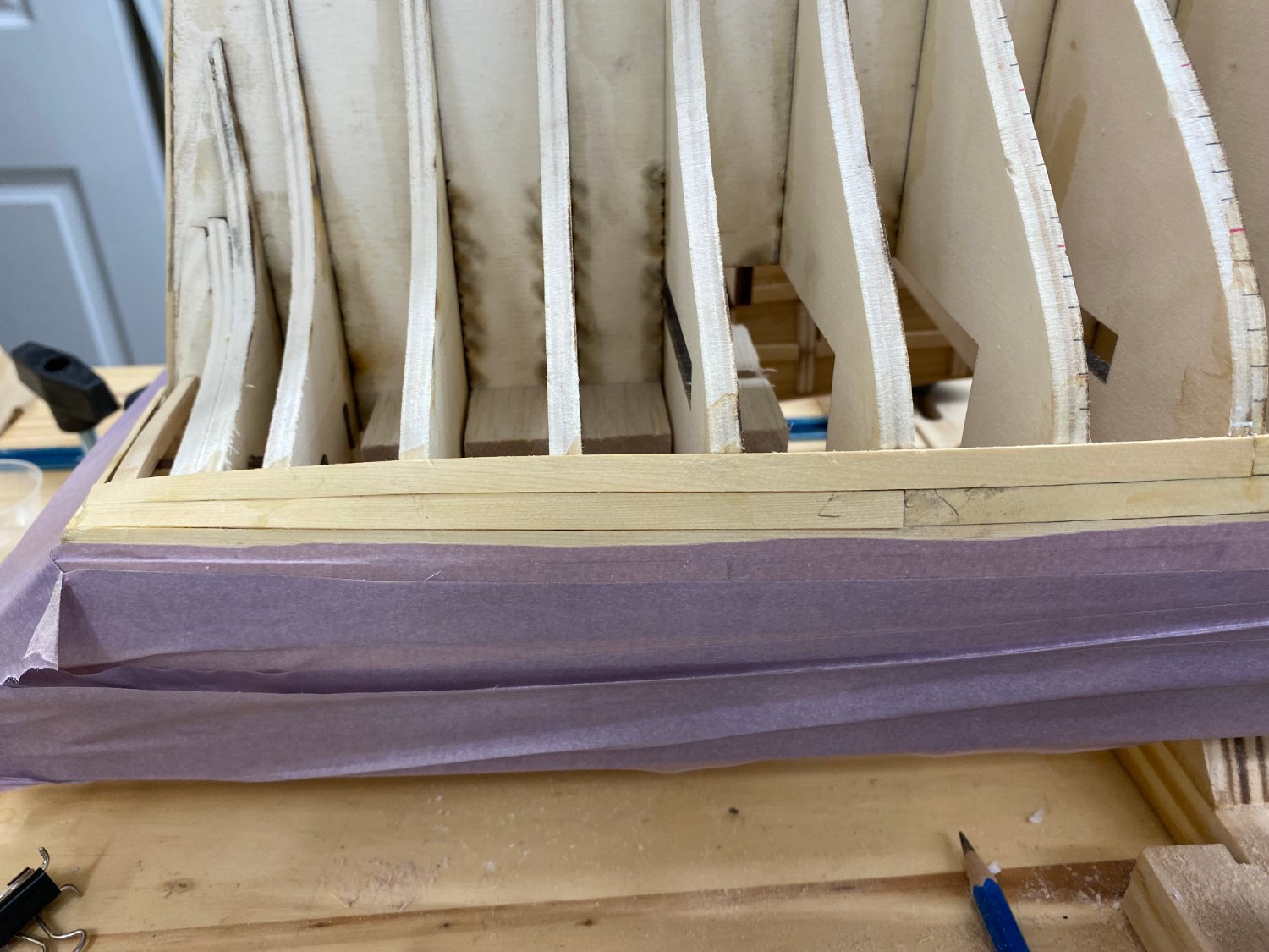
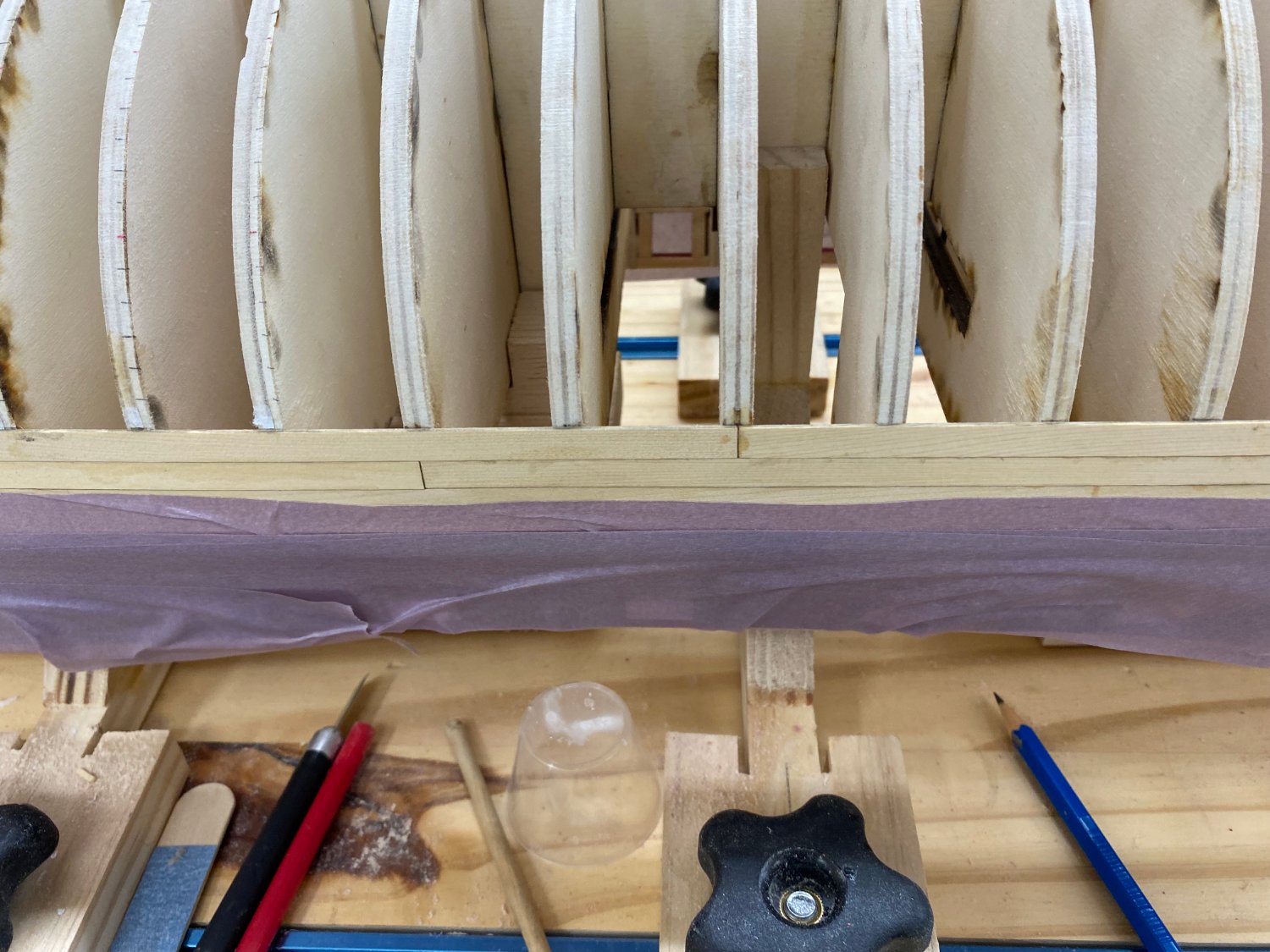
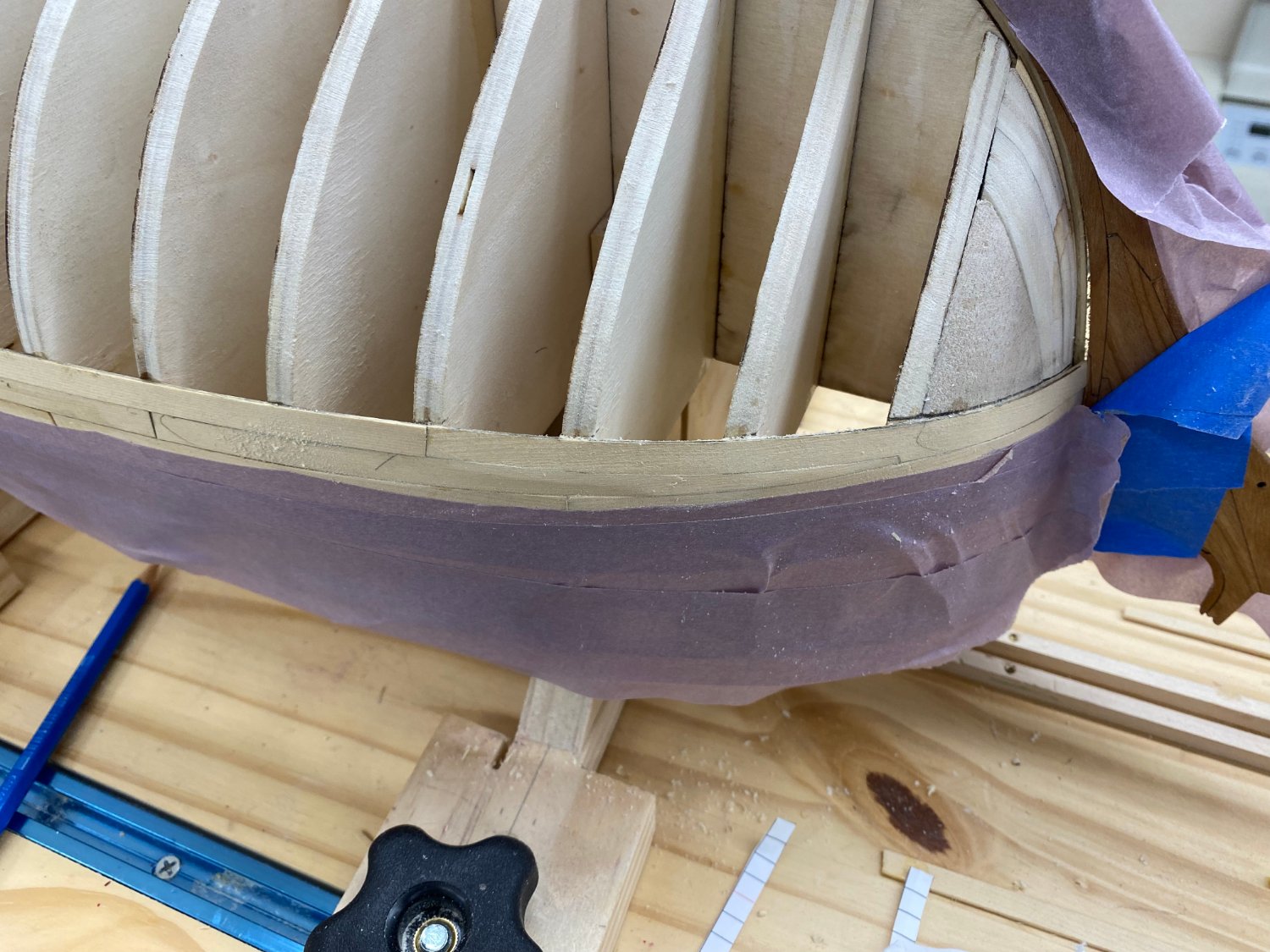
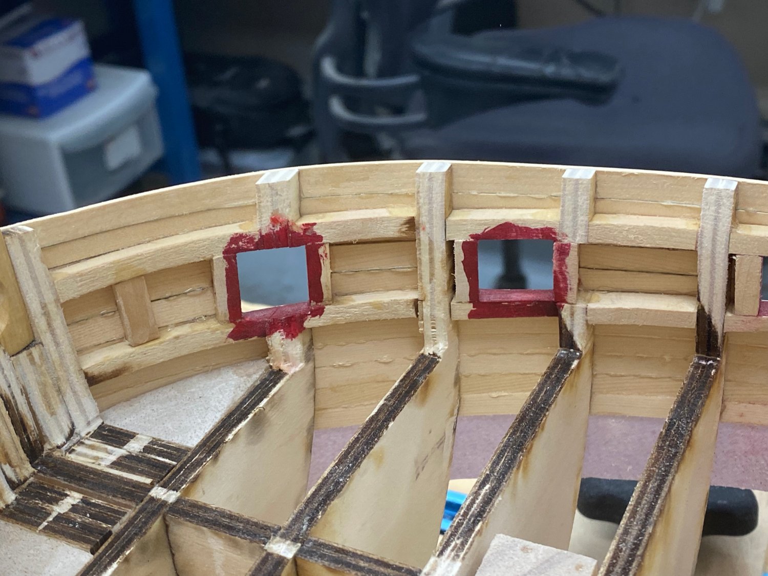
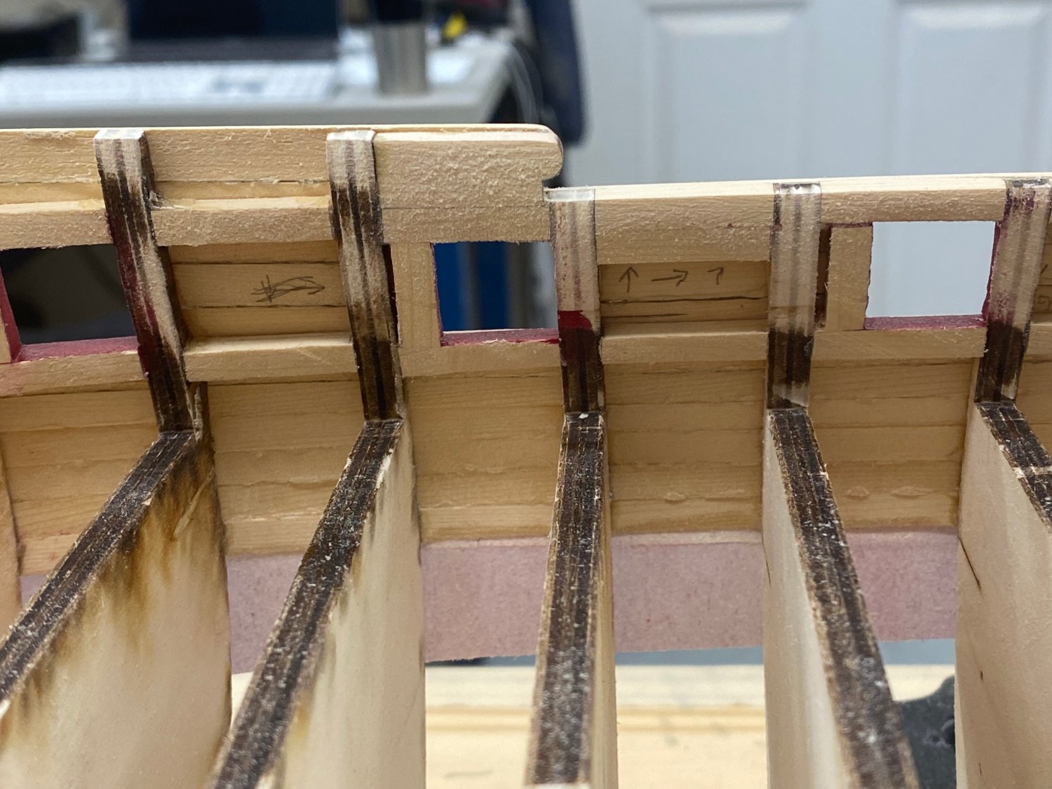
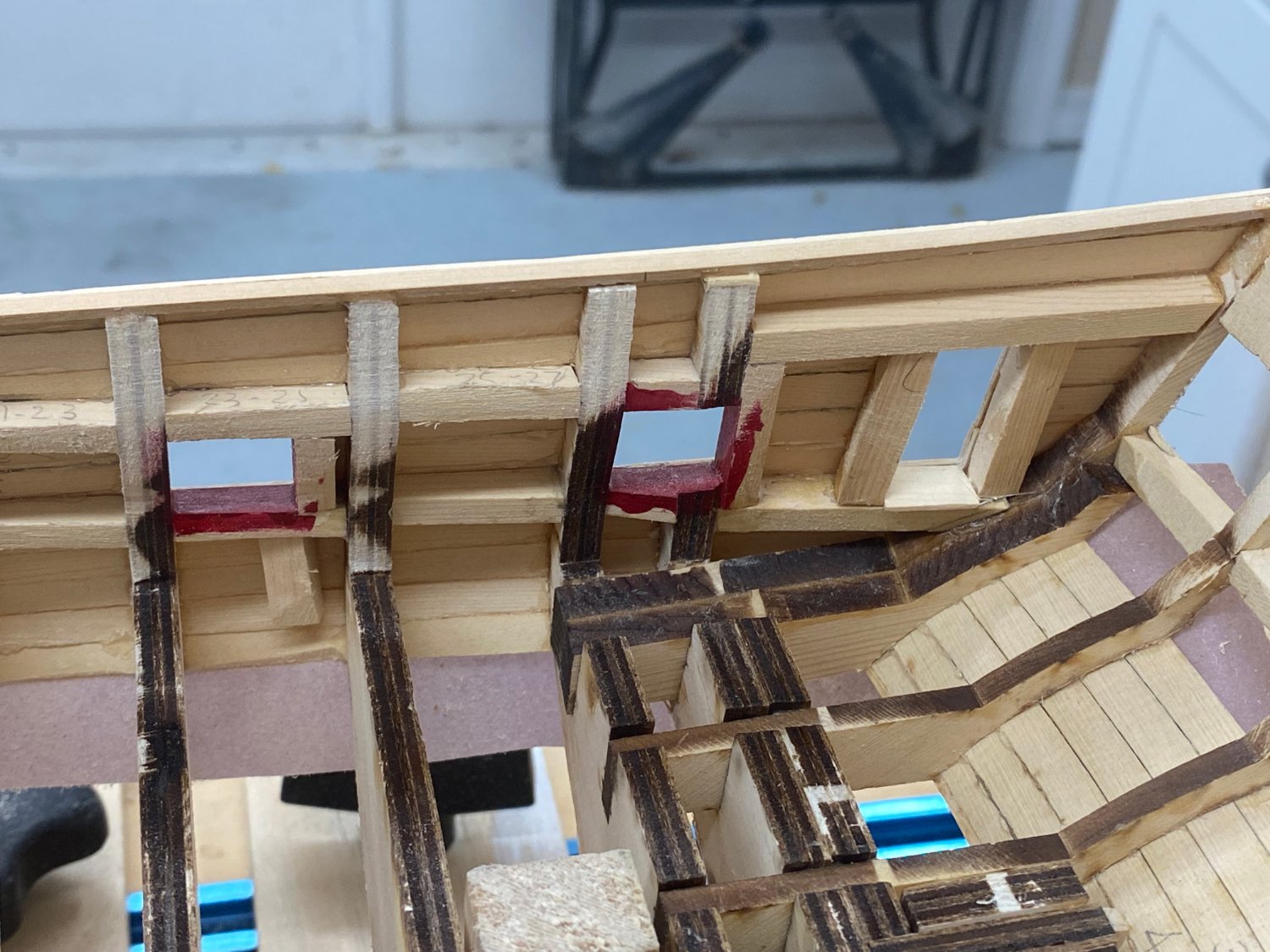
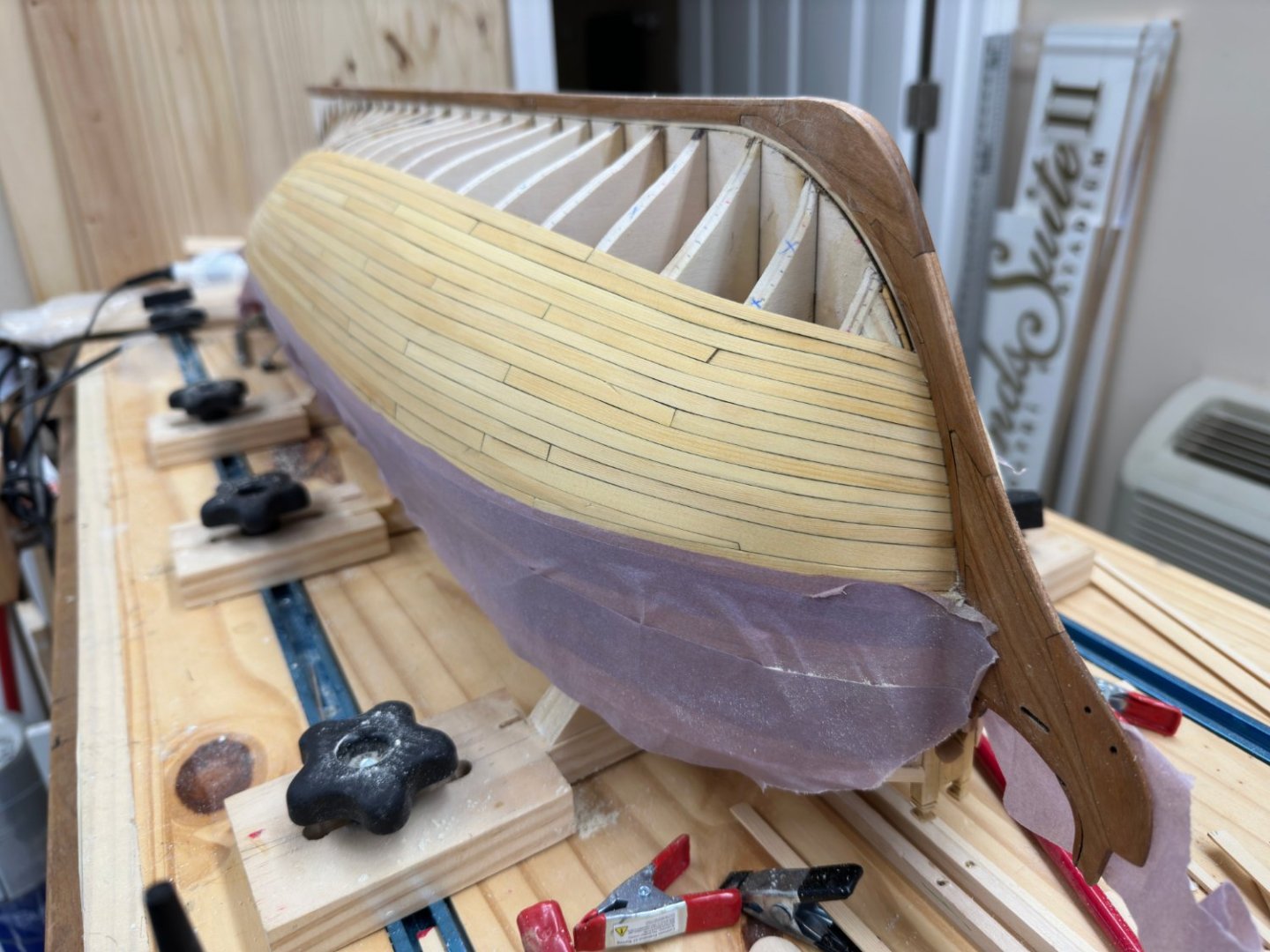
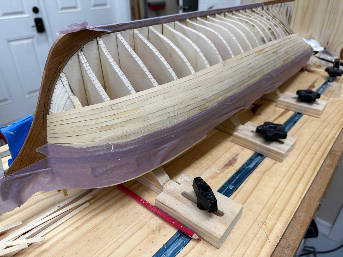
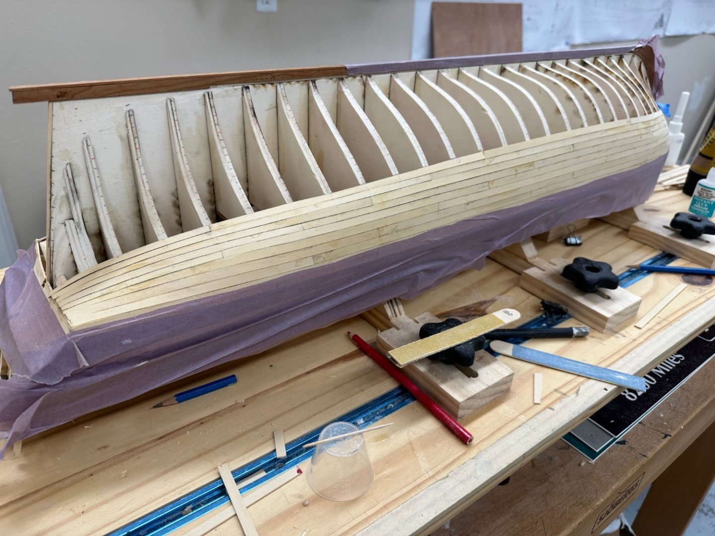
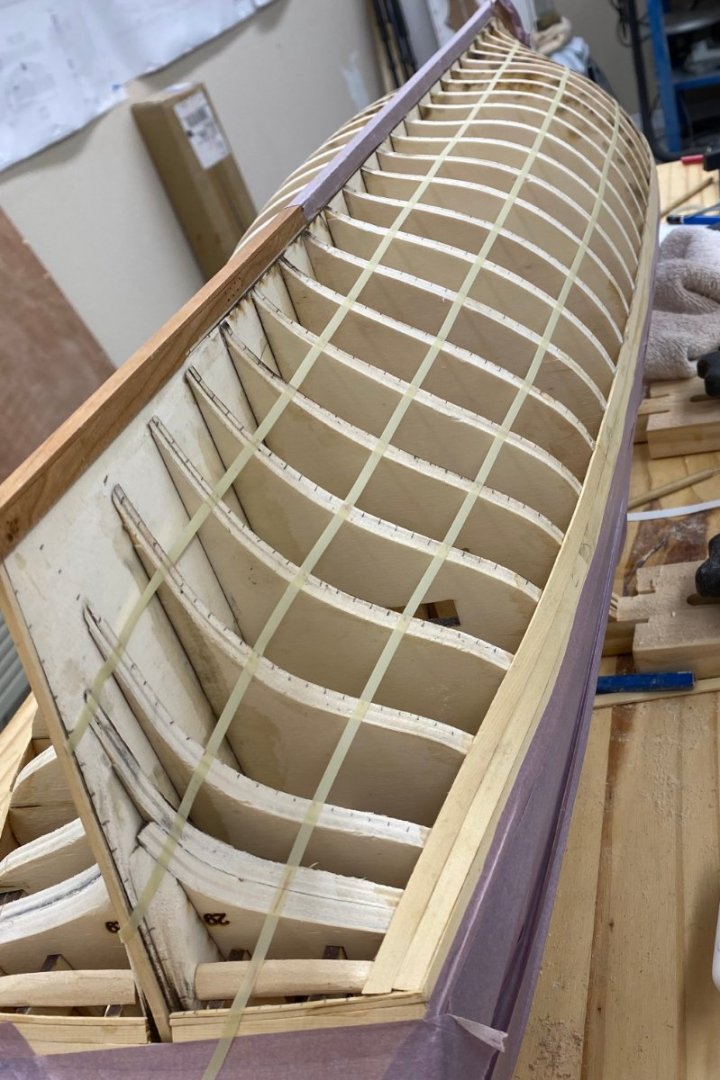
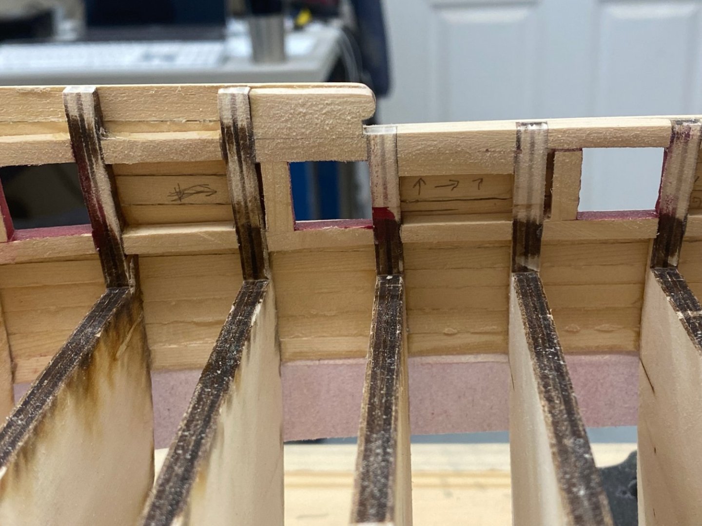
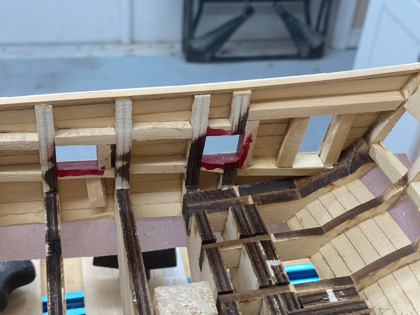
Interior fairing is done. I spent just a bit more than eight hours going over each side in three passes with 100 grit sandpaper and sticks. For all those how may build Winnie in the future it would pay dividends to try and minimize the amount of material inboard when installing the upper, lower and vertical gun port timbers. Take it from me it is much easier to sand off the excess material (and there can be more a 1/16th" excess depending on the exact location) if it is on the outside of the hull. Now it is time to turn the hull over and plank the bottom - as I mentioned previously I am going to do the entire below wales planking now and then add the second layer and black strake rather than do that after adding the first two rows below the wales.

- 389 replies
-
- 4
-
-
- winchelsea
- Syren Ship Model Company
- (and 1 more)
-
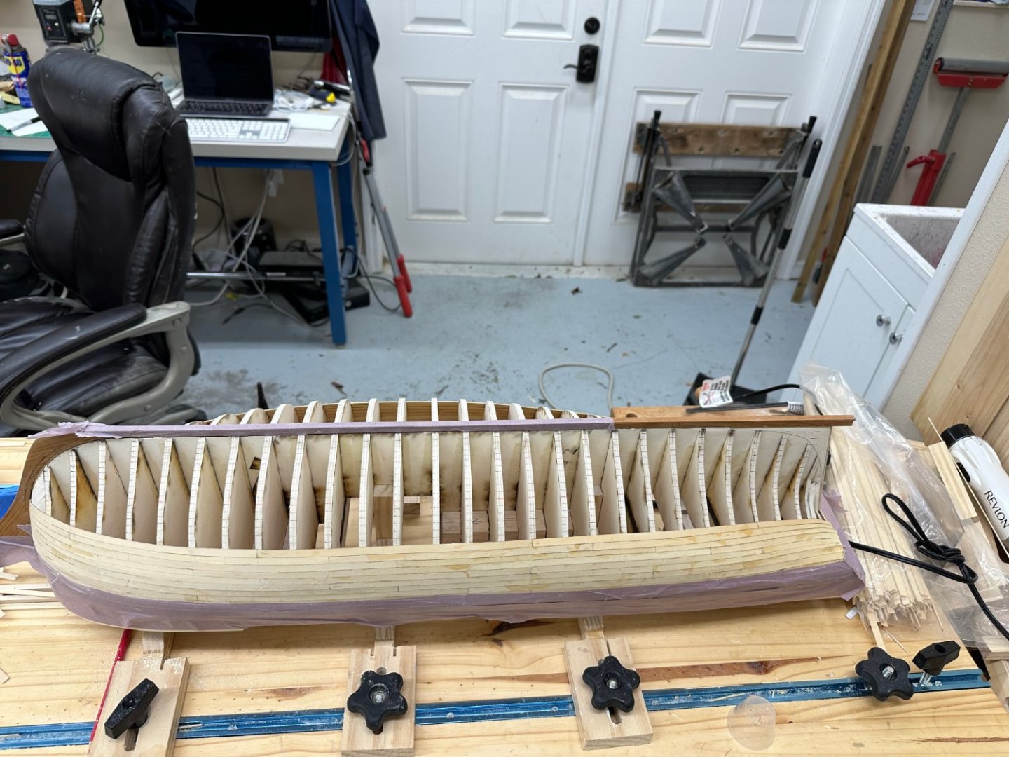
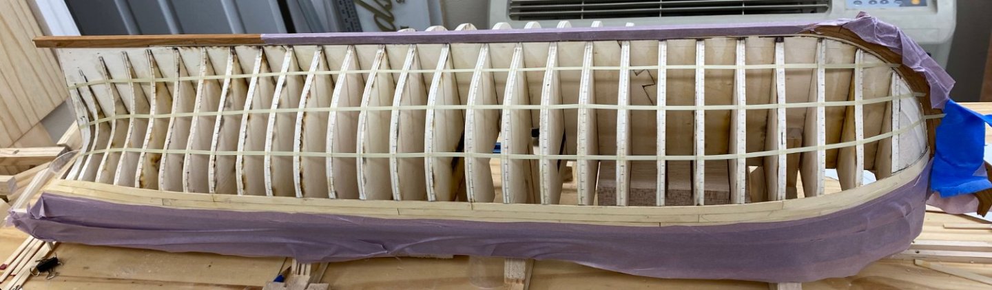
The port side above the wales planking took a good deal longer than the starboard side but the extra time I think paid off as at least the color variation is under better control. I am building the gun carriages during lulls in the planking and will continue that effort while working the below wales planking. I did deviate from the plank width on the plans twice, substituting 5/16" for 1/4" both times as the 1/4" was just a bit too narrow. We will see what impact this has as we go forward. I am planning on planking the entire bottom before putting the second layer on the wales as I do not want to "injure" them during the planking process (drop something on them for instance) and I am still "on the fence" about using walnut instead of cedar and not painting them. I will thin the bulwarks now before I turn the hull over to do the bottom. Here is the port side. I have no clue why the last picture has a marked different "hue" than the others. They were all taken within a minute of each other. Perhaps it is because the aft end is closest to the wall but...


- 389 replies
-
- 6
-
-
- winchelsea
- Syren Ship Model Company
- (and 1 more)