HOLIDAY DONATION DRIVE - SUPPORT MSW - DO YOUR PART TO KEEP THIS GREAT FORUM GOING! (Only 72 donations so far out of 49,000 members - Can we at least get 100? C'mon guys!)
×


cdrusn89
-
Posts
1,915 -
Joined
-
Last visited
Content Type
Profiles
Forums
Gallery
Events
Everything posted by cdrusn89
-
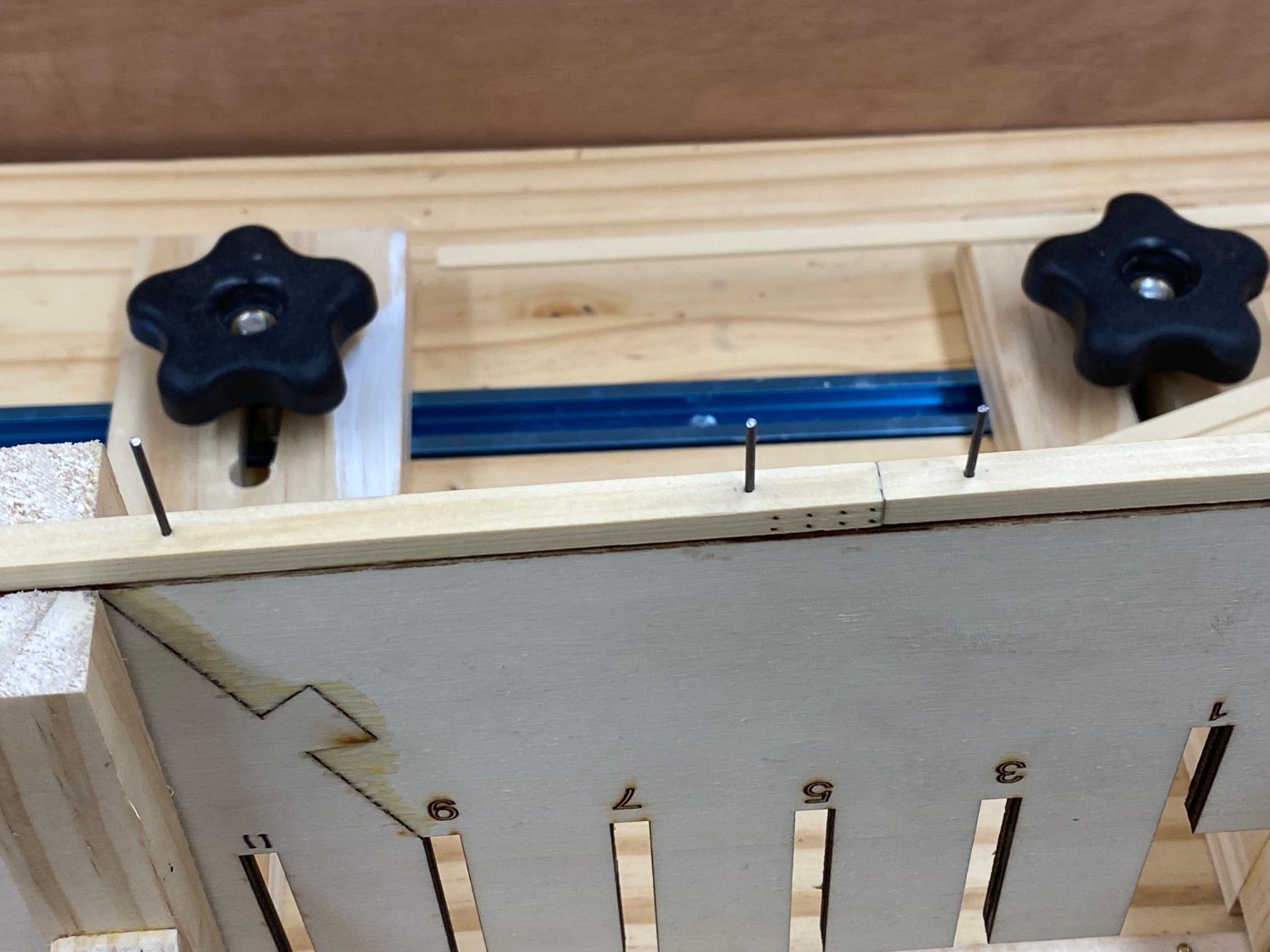
 I got the keel attached without too much drama and this morning added the simulated bolts on both sides. Then I got to thinking about the keel/rabbet strip interface. While the bulkheads are being added I think there could be the potential for some substantial stresses on this junction and since it is only 5/32" wide it might be better (for me) to have some additional reinforcement of this joint. So I drilled three holes through each keel section using a #56 drill bit. I went about 1 1/4" inches deep so I should have about 1" into the center bulkhead. I cut some .047" music wire and hammered a piece into each hole. I used a countersink to get the wire just below the keel surface. I was not too worried about denting the keel surface since it will be covered by the false keel. Anyway after I got all the wires hammered in I put a drop of thin CA on each wire. Probably overkill since I had to hammer to wire into the center bulkhead. Hopefully I will sleep better now knowing that it will take some pretty serious force to get the keel off the center bulkhead. The next thing I am considering is drilling the holes for the mounting pedestals. I did this on Confederacy at this point and almost forgot that I had done it (senior moment). I drilled these holes freehand, for the mounting holes I need a better system for making sure they are straight. But I need the false keel installed before we get to that. Here are some of the wires before they were "pounded home". You can also see one set of the simulated bolts. I used a #76 hole and 26 lb line (Chuck used #77 and 15 lb line) because that is what I have - 450 meters of it. Should last a lifetime of model building.
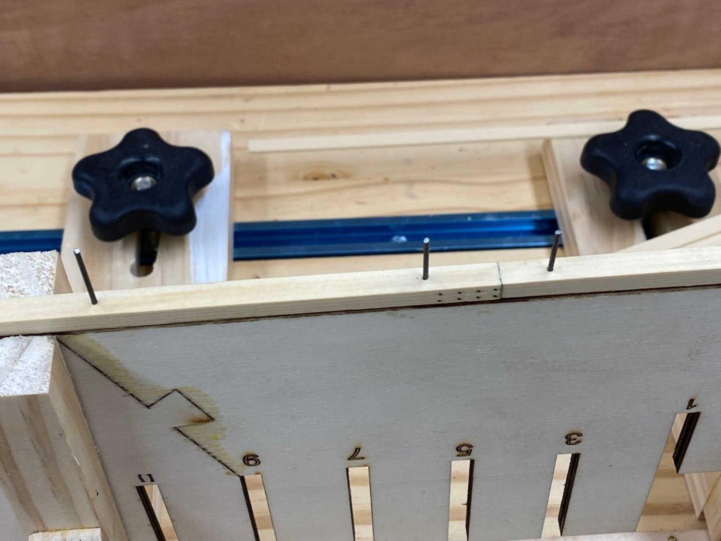
- 389 replies
-
- 5
-

-
- winchelsea
- Syren Ship Model Company
- (and 1 more)
-
Thanks Frank. It looks like it will be a great "experience".
- 389 replies
-
- 1
-
-
- winchelsea
- Syren Ship Model Company
- (and 1 more)
-
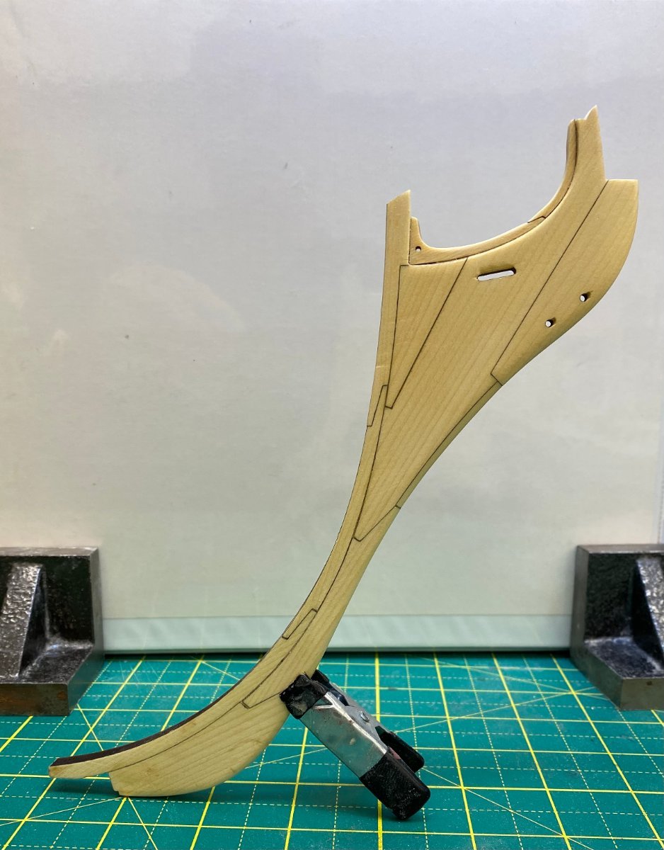
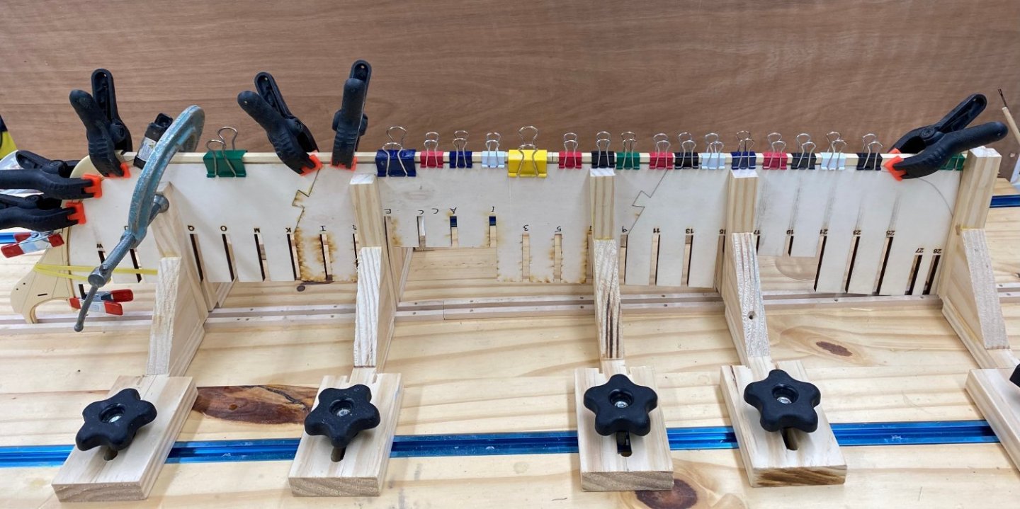
I thinned down the stem piece even more after I took the pictures above. Assuming that if more thinning is required I can do it with the stem attached to the center keel I decided to attach the stem and keel pieces to the hull. Here is the center keel with the stem and keel attached drying on the build board. Did I mention you can never have too many clamps.
- 389 replies
-
- 5
-
-
- winchelsea
- Syren Ship Model Company
- (and 1 more)
-
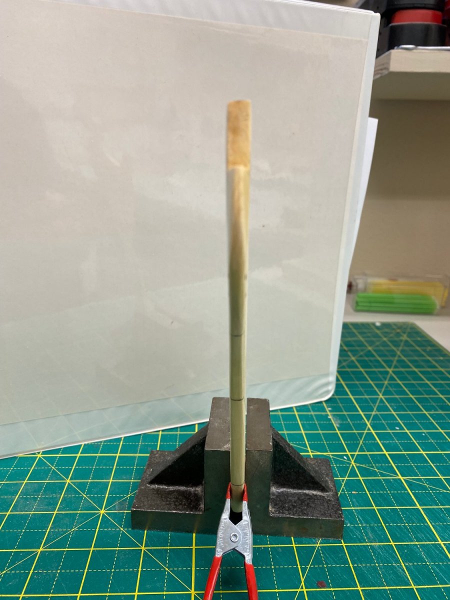
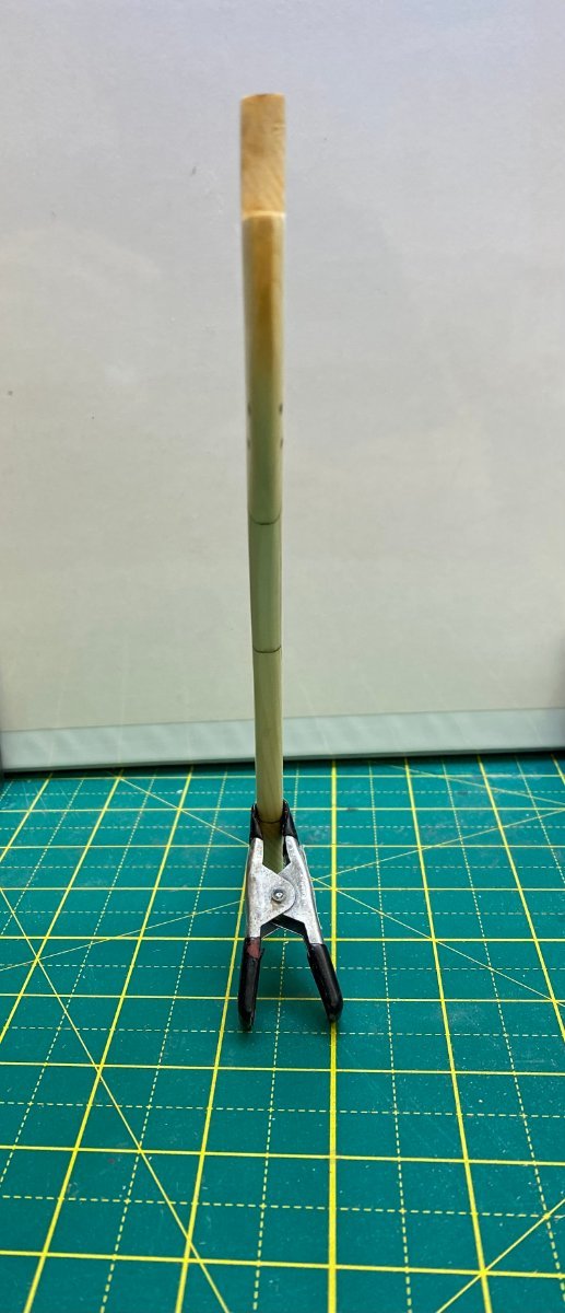
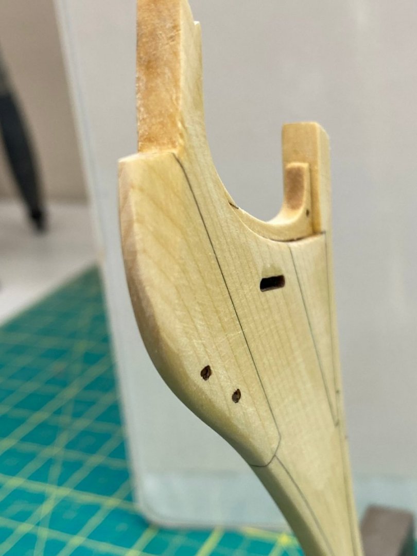
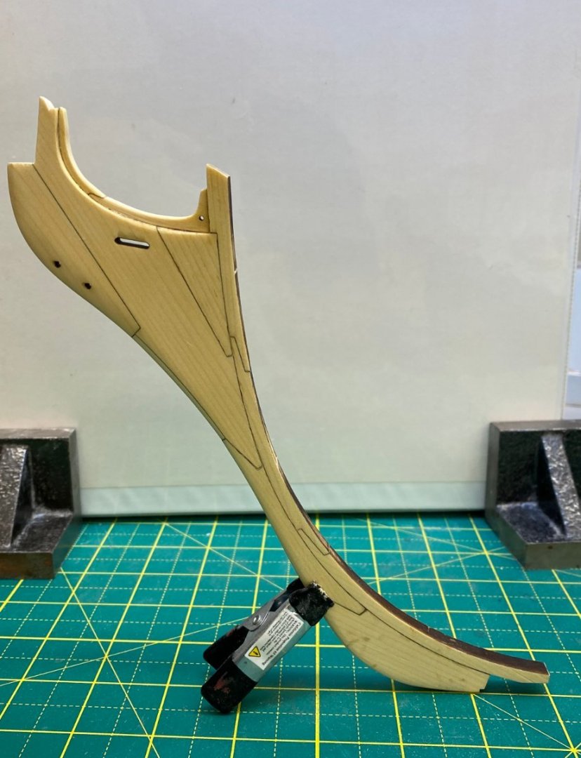
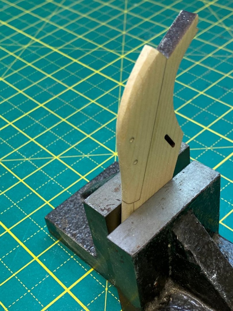
After reading Chuck's note above I went back and did some more sanding to try and get the taper rather than rounded look. Not sure I am there yet. How far down the stem does the taper extend? all the way to the waterline? Lower? Here is what it looks like now.
- 389 replies
-
- 4
-
-
- winchelsea
- Syren Ship Model Company
- (and 1 more)
-
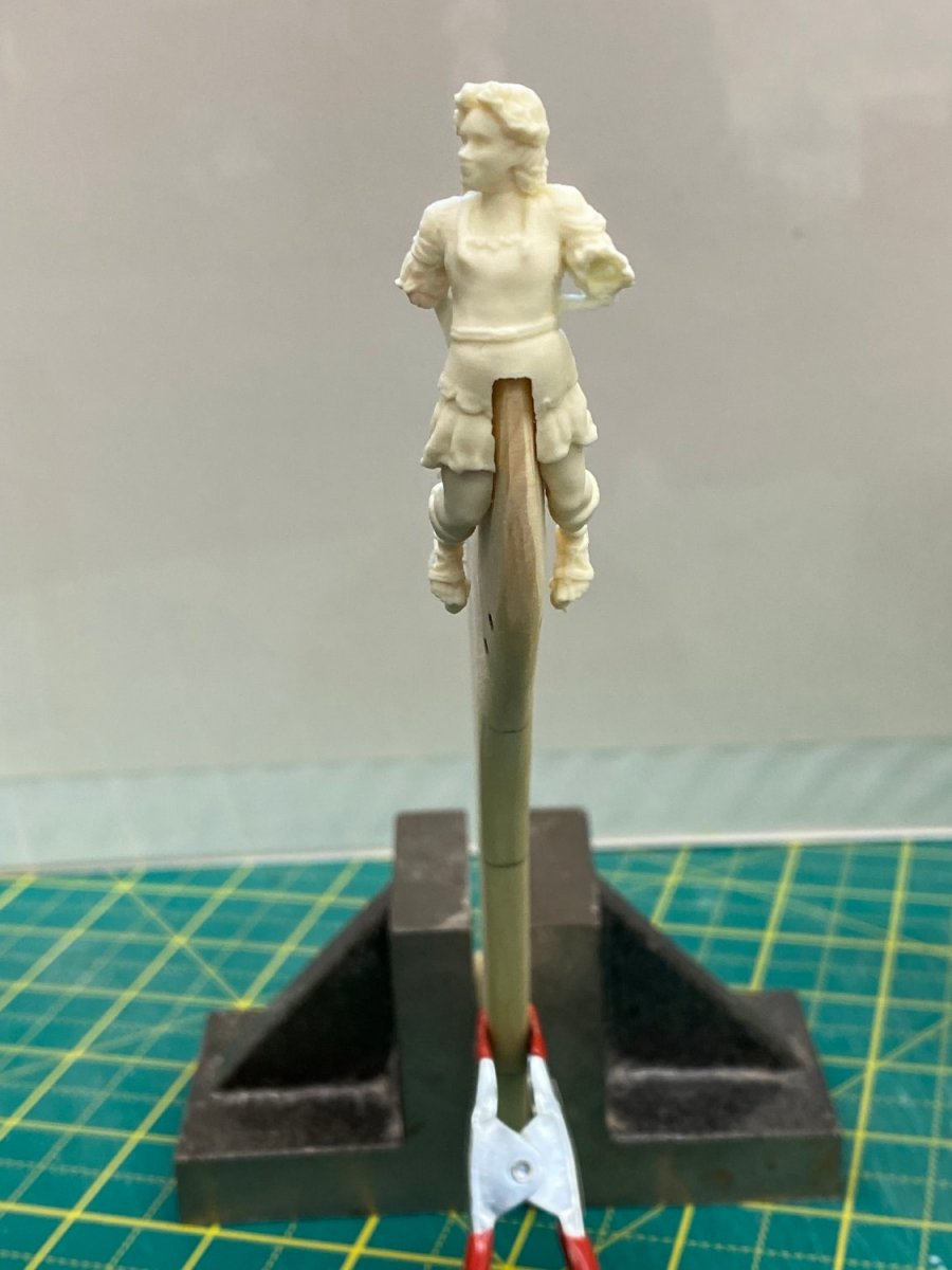
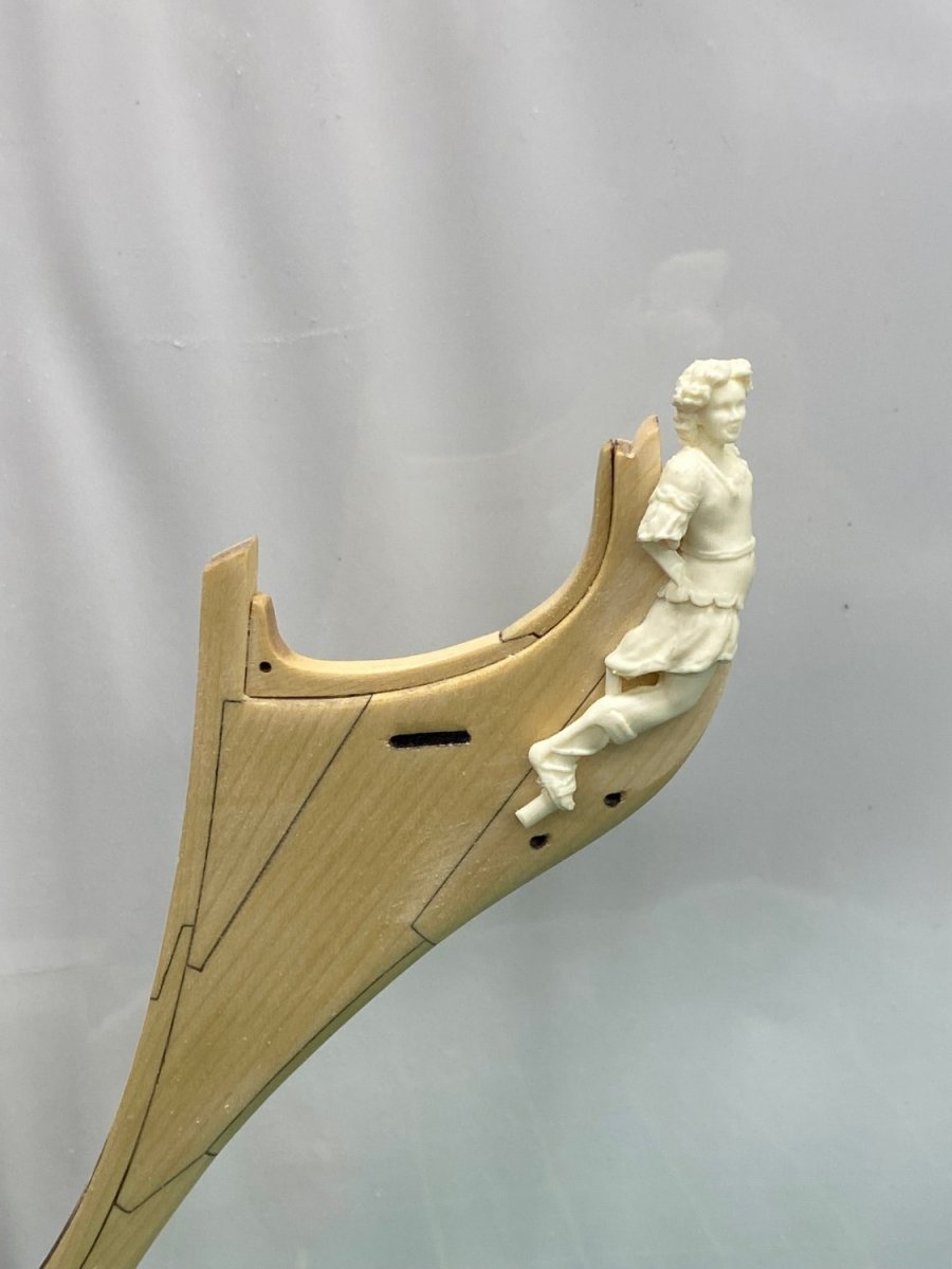
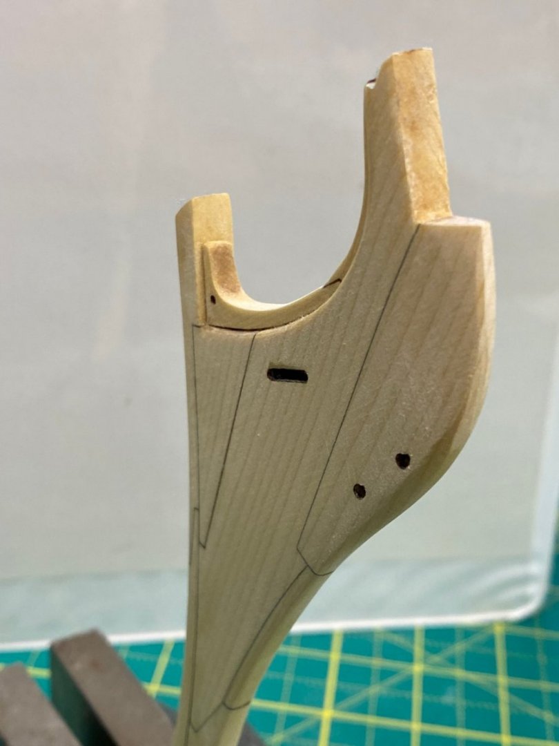
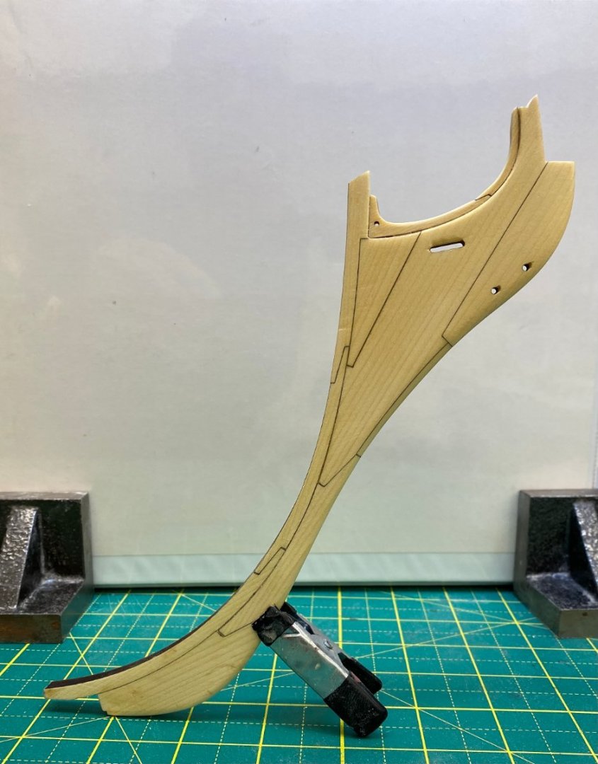
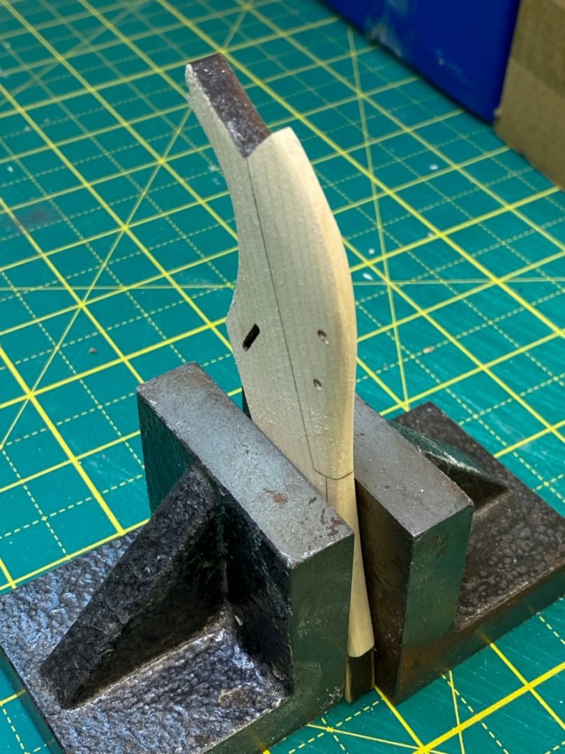
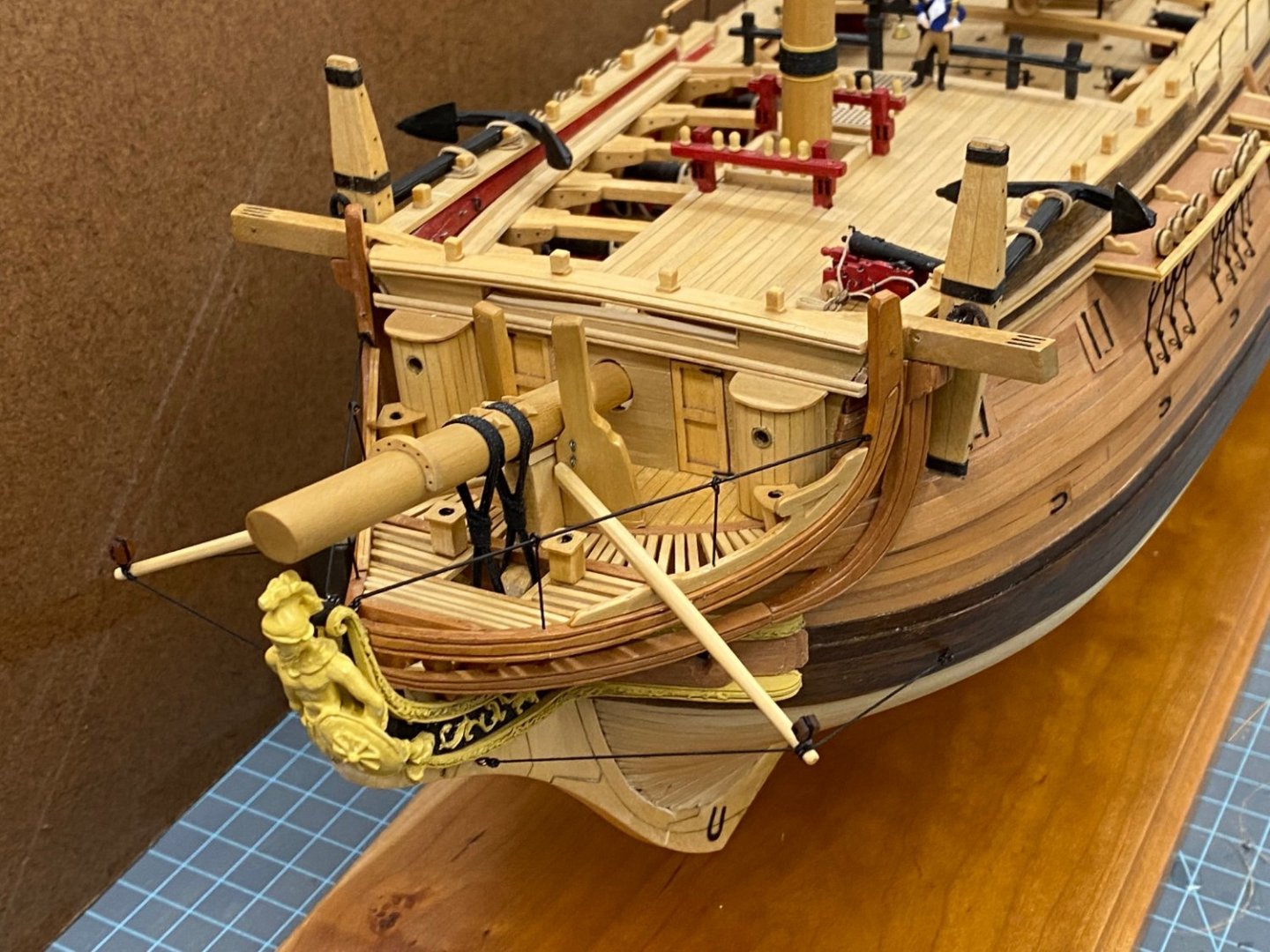
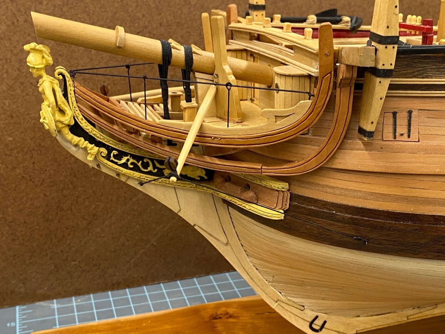
While I was adjusting the stem to fit the center keel and remembering Chuck's example of having to make the figurehead too squat if the stem is too wide I decided, since I have the resin figurehead already) to see if I had tapered the stem enough. Good thing as I was a good deal too wide. I probably could have recovered by widening the resin figurehead but since I was only one coat of WoP into finishing the stem I should probably make the adjustment on the stem. So here is the stem with figurehead "aboard". And I came to this realization before I saw Chuck's note above. Sometimes "great minds, etc., etc."


- 389 replies
-
- 6
-
-
- winchelsea
- Syren Ship Model Company
- (and 1 more)
-
Thanks Rusty and Oldsalt. I put the first coat of WoP with the stem detached. A preliminary fitting shows that I will need to "adjust" the stem both top and bottom to get a satisfactory fit. I will put a second coat of WoP (not on the mating surface) before I start the "fitting" process.
- 389 replies
-
- 1
-
-
- winchelsea
- Syren Ship Model Company
- (and 1 more)
-
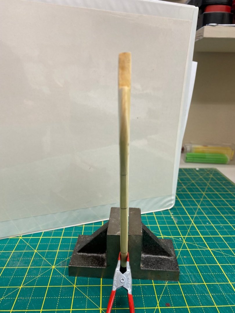
I finished the assembly of the stem. Once I had the all the pieces assembled it turned out my apprehension about the fragility of the assembly was for nothing. With all the pieces in place the assembly appears very capable of having the tapering and char removal done after assembly. Hopefully it does not make a difference in which order the steps are accomplished. Here is the stem after 320 grit sanding and a wipe down with paint thinner. WoP is next.

- 389 replies
-
- 10
-
-
- winchelsea
- Syren Ship Model Company
- (and 1 more)
-
I turned the center keel upside down and moved it so the bow was off the end on the right so I could add the breading line strip. Once I got the correct size strip (5/32 X 1/16) everything went "according to plan". Here is the center keel with all the breading line strip added. Per the instructions I did it in three sections plus the stern post.
- 389 replies
-
- 8
-
-
- winchelsea
- Syren Ship Model Company
- (and 1 more)
-
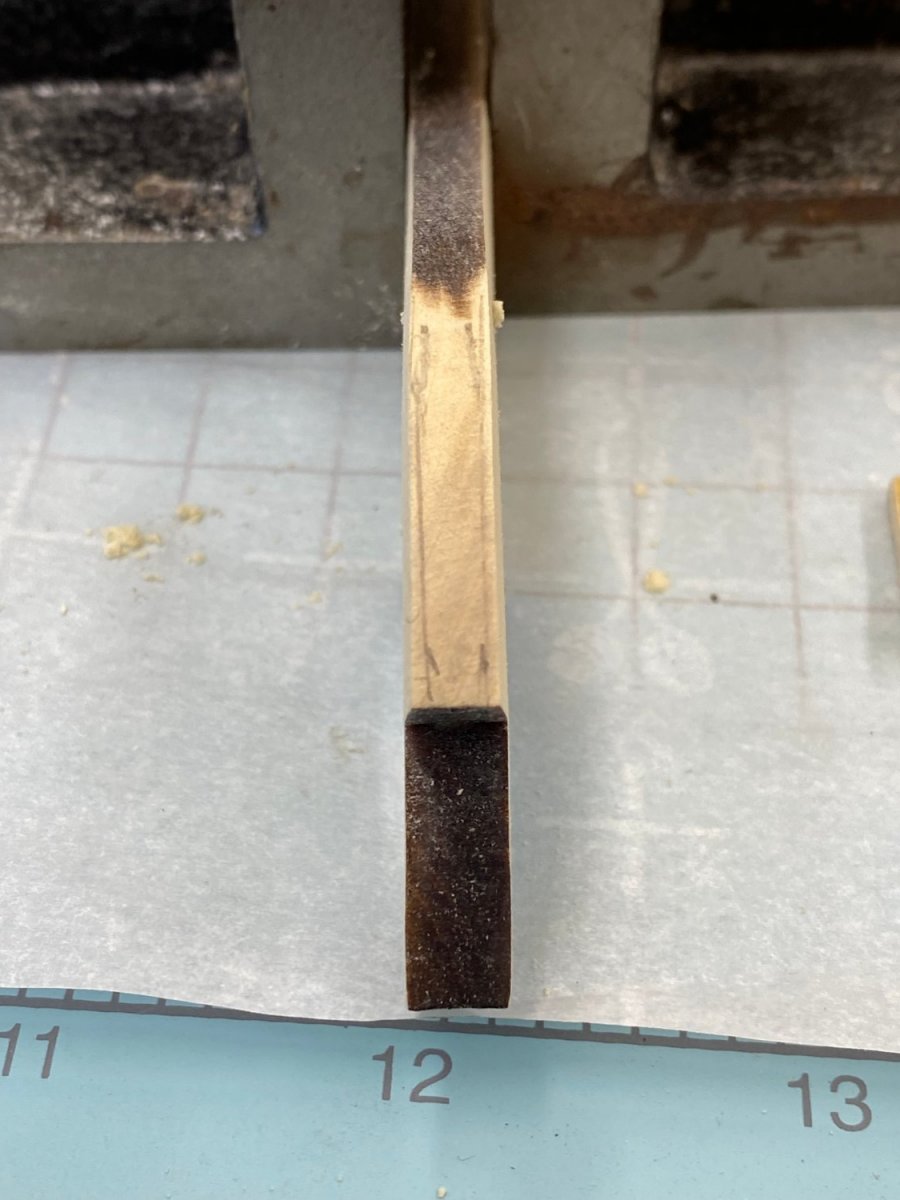
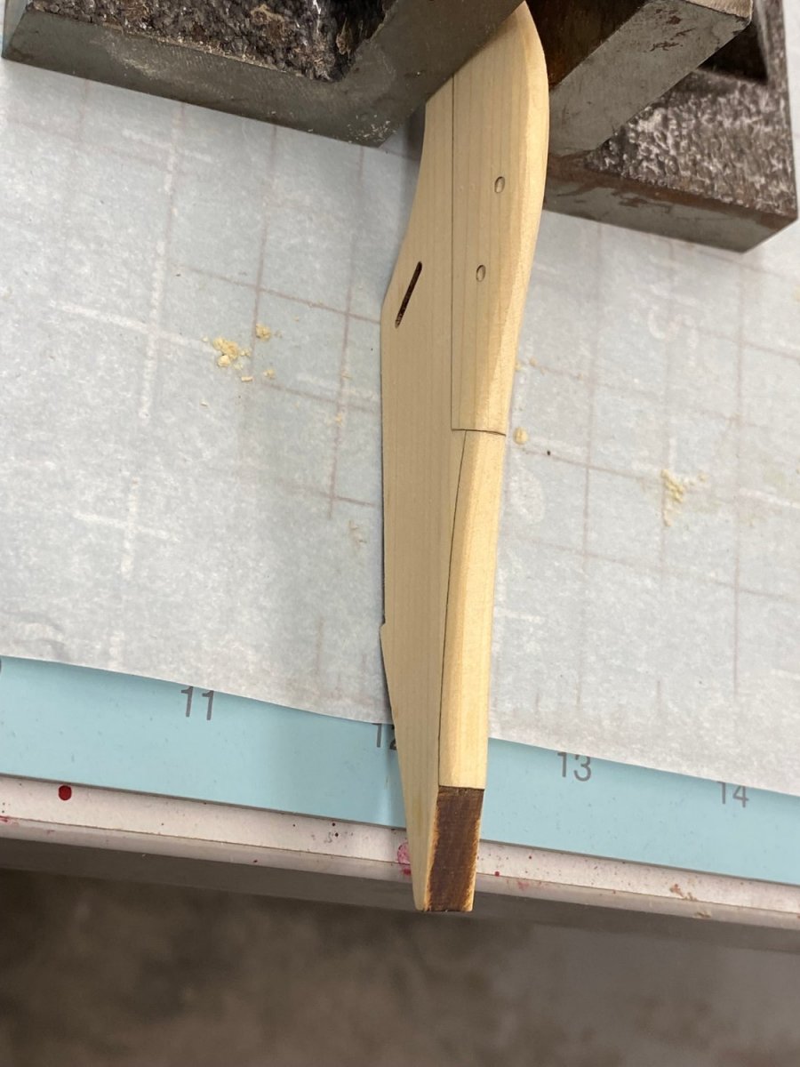
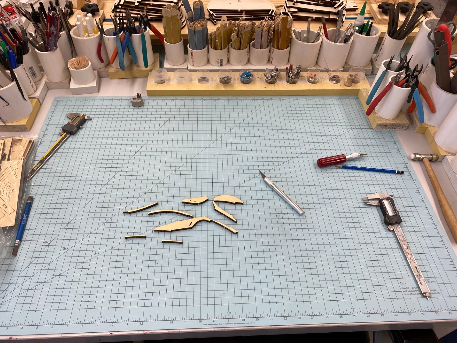
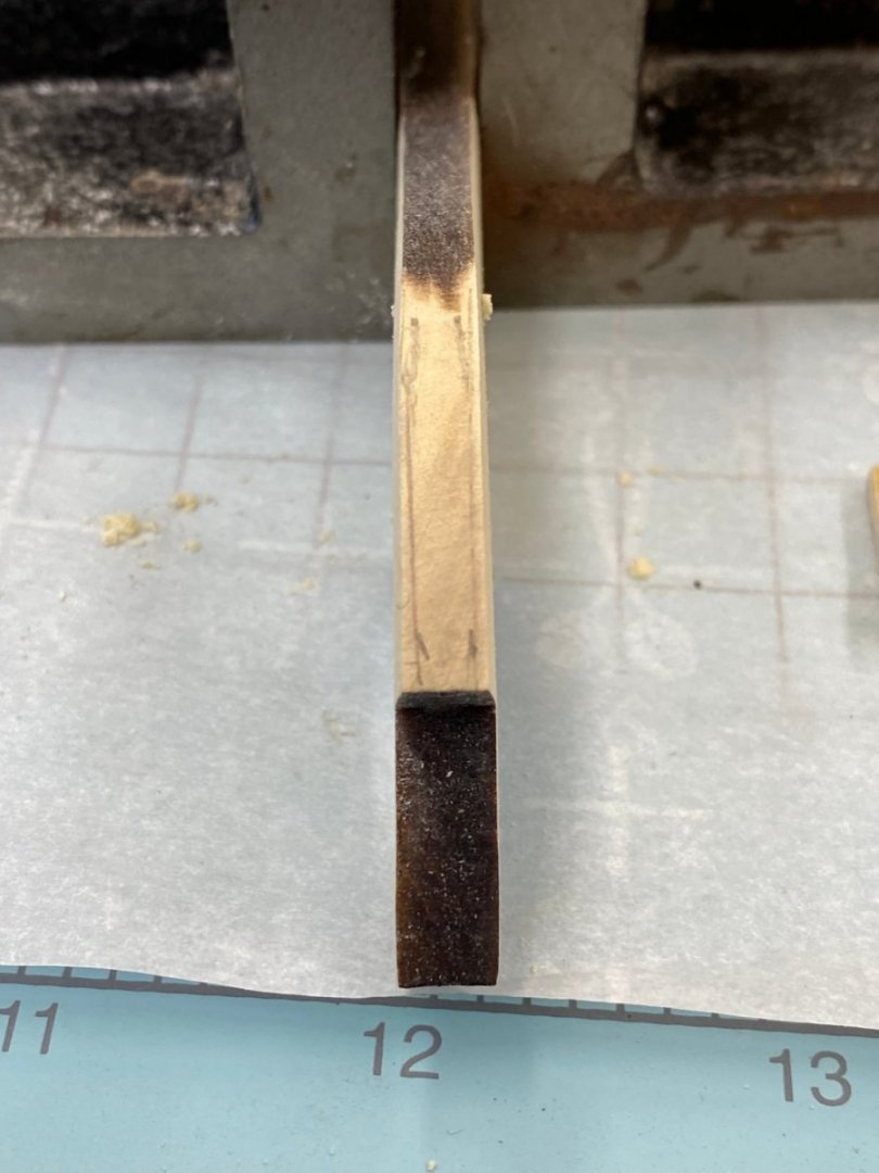
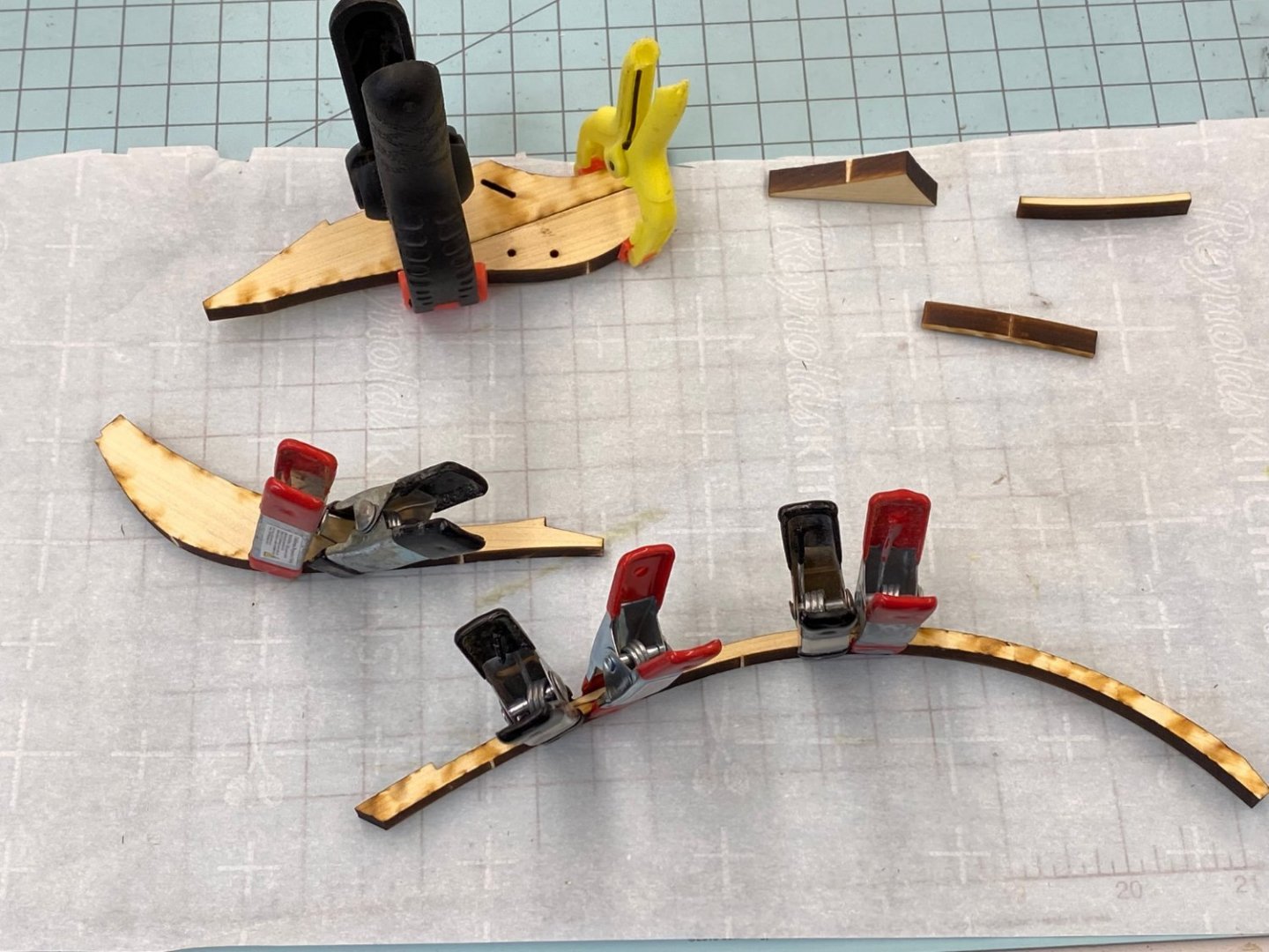
Thanks guys. I assembled the stem pieces as shown above and then thought that maybe it might be a better idea to do the tapering and char removal (where required) with the smaller pieces before gluing the entire stem assembly together. I don't know about everyone but that assembly looks pretty fragile, even out of 1/4" material to me. So I did the tapering and easing of the edges and char removal on the part that contains the bobstay piece. I started by marking the edge (after careful removal of the char) 1/16" in from each side. I used a 1/32" X 1/8" batten laid on the stem piece and centered to mark the line to which the piece needed to be thinned. Here it is after I started thinning. I continued thinning and removing the char from the outboard edges. Here is what it looks like after thinning, easing and char removal. I did most of the thinning with 180 grit paper and then followed with 220 grit. I will go over the completed stem assembly with 320 grit before applying the WoP.

- 389 replies
-
- 8
-
-
- winchelsea
- Syren Ship Model Company
- (and 1 more)
-
The keel is laid - well not really the keel but the first pieces of the stem have been glued together. The seams look really tight without doing anything to the pieces, at least so far. I have convinced my girlfriend that using the granite countertop as the base for gluing the center keel together will not be a problem and it only needs to dry overnight so it will not get in the way of breakfast. Maybe it would have been easier to just go buy a sheet of glass 3' X 1' but where is the adventure in that?
- 389 replies
-
- 9
-
-
- winchelsea
- Syren Ship Model Company
- (and 1 more)
-
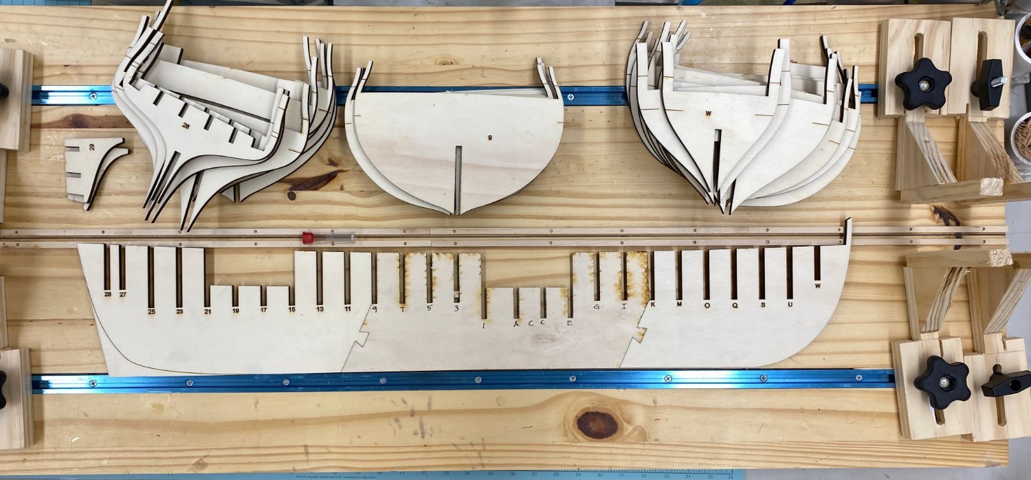
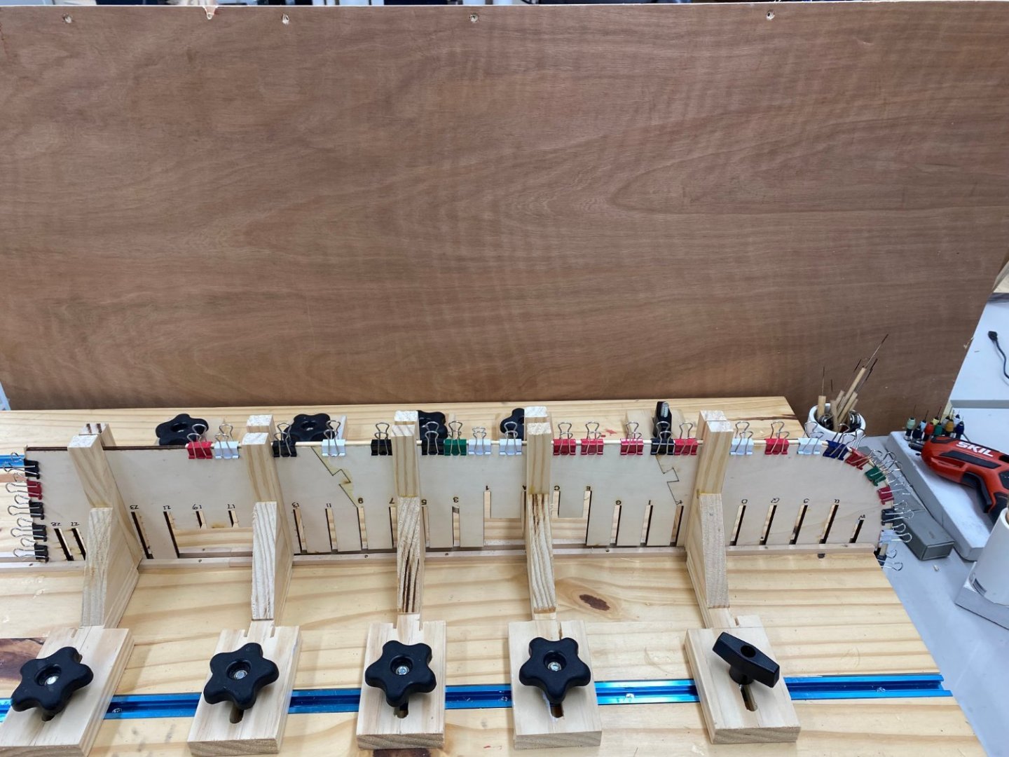
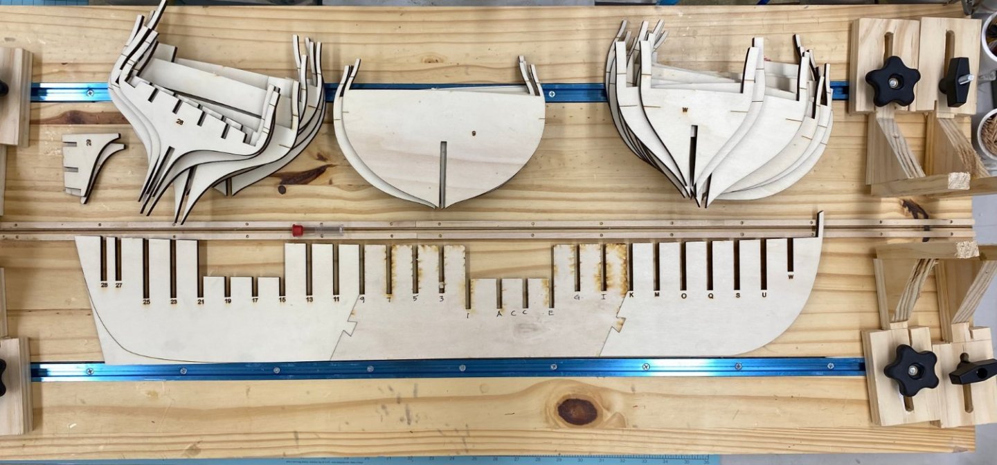
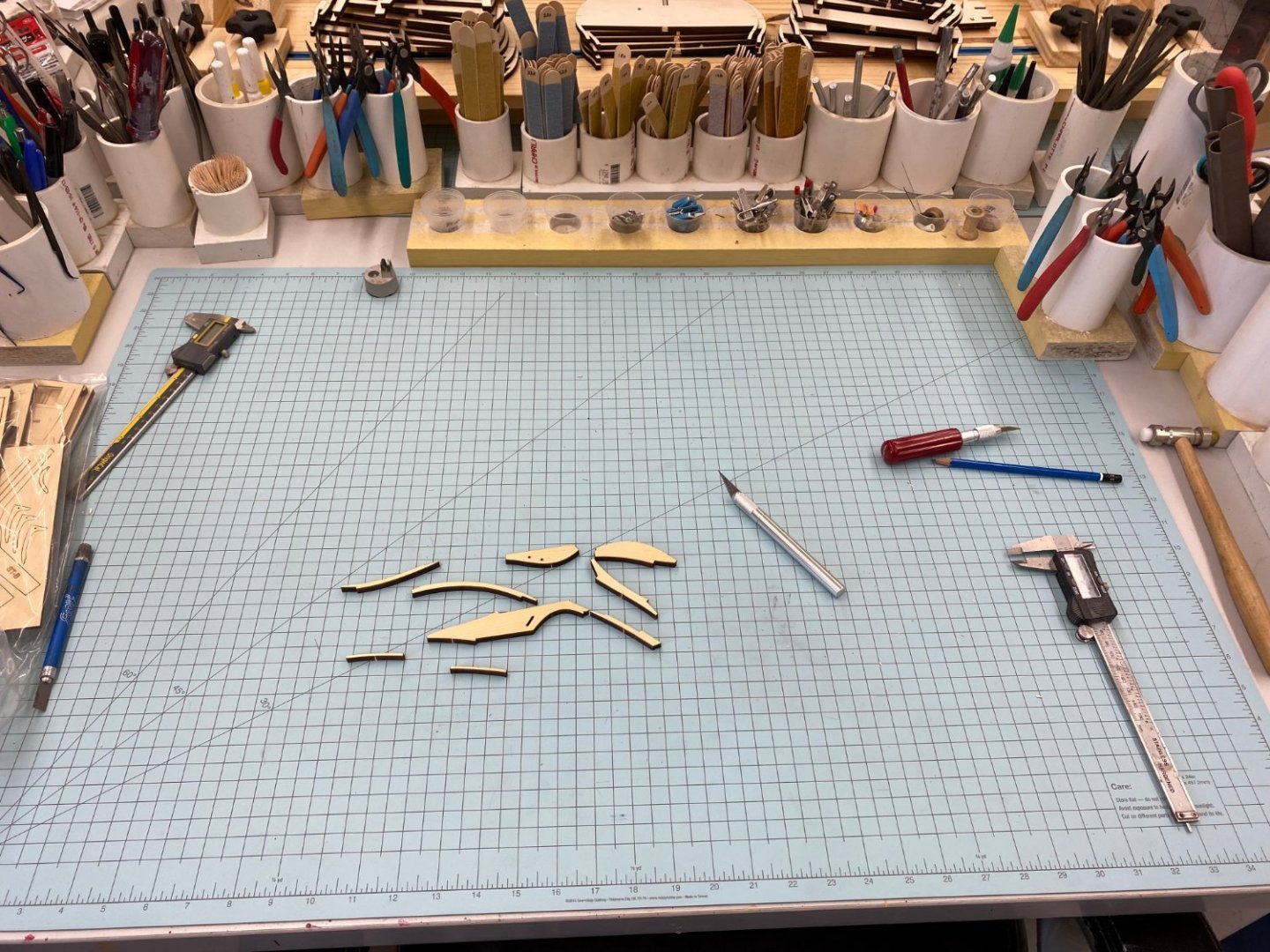
So I finished the USF Confederacy from Model Shipways and have room in my ship model cabinet for one more model but it has to be "Admiralty" size (i.e. less than 14" high). So not wanting to pay for all the masts and rigging I decided to try my hand at Winchelsea. I spent the last few days cleaning up the workshop and getting ready to start although I will not get too far as we leave for three weeks the end of the month. So here we go. I spent a good deal of time on the build board as suggested in Chuck's monograph. I used this same build board for the initial stages of Confederacy construction so I thought it would work here as well. As it turned out all (or almost all) of the "fittings" that I made to hold the center keel are too wide to fit between the bulkheads here since there are markedly more than is usual in a POB model. So I made ten new, 3/4" wide ones. Hopefully they will work out but "no plan survives first contact with the enemy". Here is the build board with the center keel and bulkheads. I would point out that there where several instances where the laser cutter did not go all the way through the plywood and I had to cut through the last layer by hand (besides removing the usual "tabs"). I lost a layer of plywood on the bulkhead extensions on three of the bulkheads but do not think that will present a problem. I noticed that the center keel fits together with the center section upside down relative to the front and back - you can see the laser marks on the center section but not on the front and back. I assume this is to take advantage of the slightly offset angle that the laser cuts at (rather than completely perpendicular to the wood surface). This way should produce a tighter fit than having them all with the same side up. Since the keel/bulkheads are not the first step I also laid out the pieces of the stem (I bought the Chapter 1 wood package in Yellow Cedar) on the workbench adjacent to the build board. And now let the fun begin!!
- 389 replies
-
- 16
-
-
- winchelsea
- Syren Ship Model Company
- (and 1 more)
-
Thank Tim - Hopefully I am improving my technique with each iteration.
-
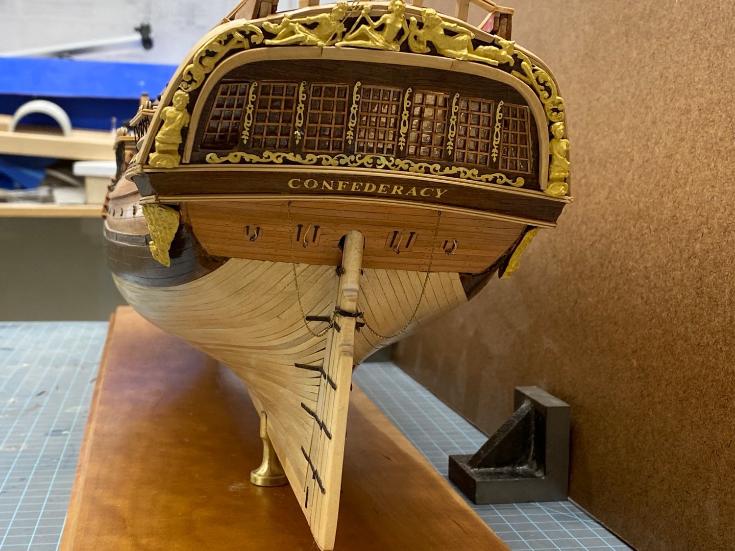
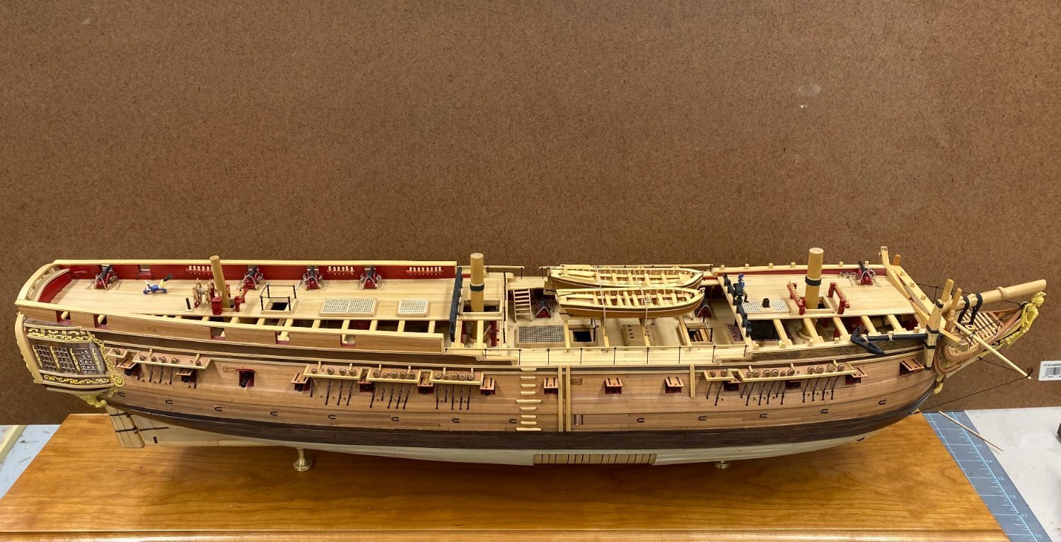
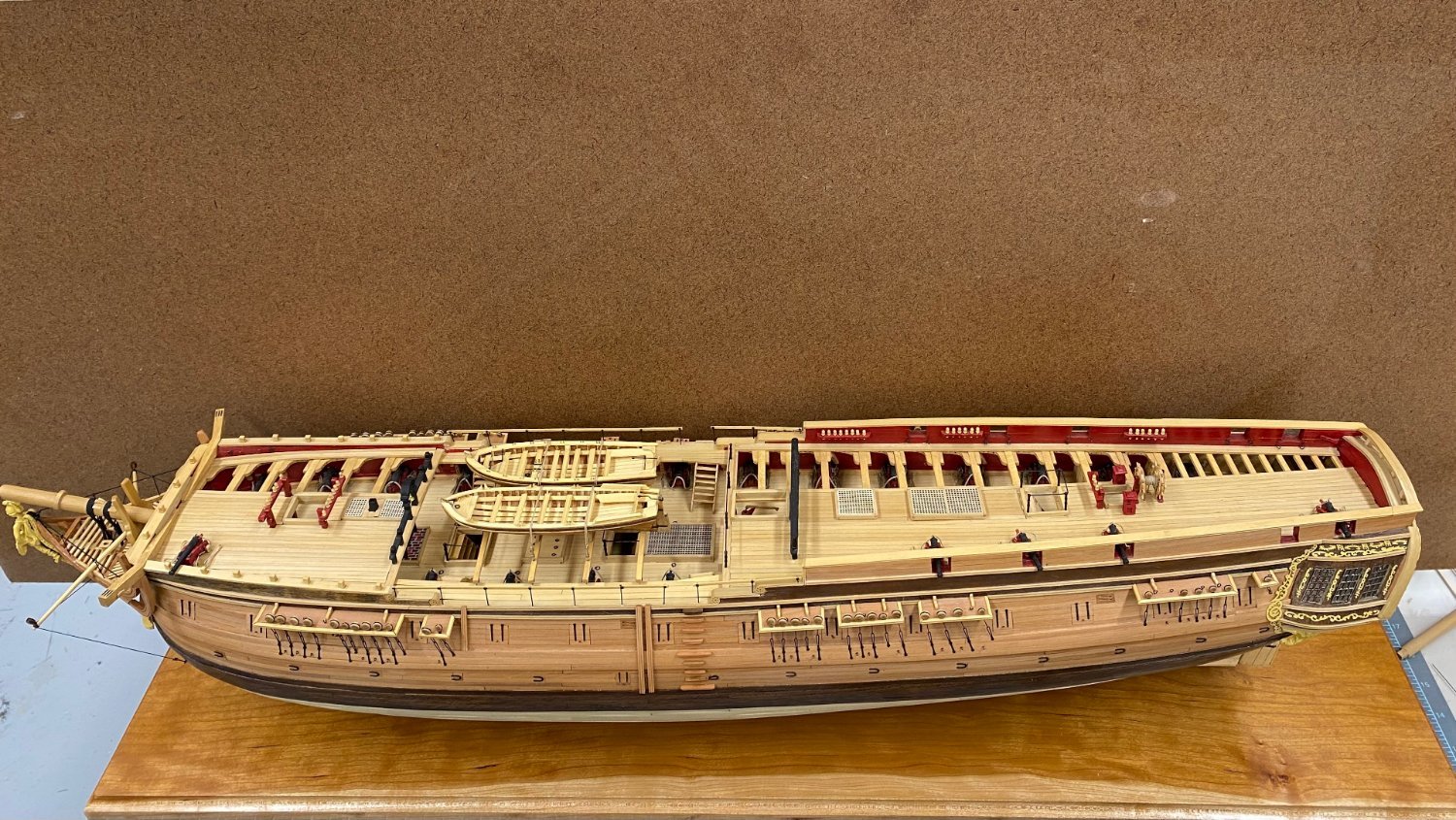
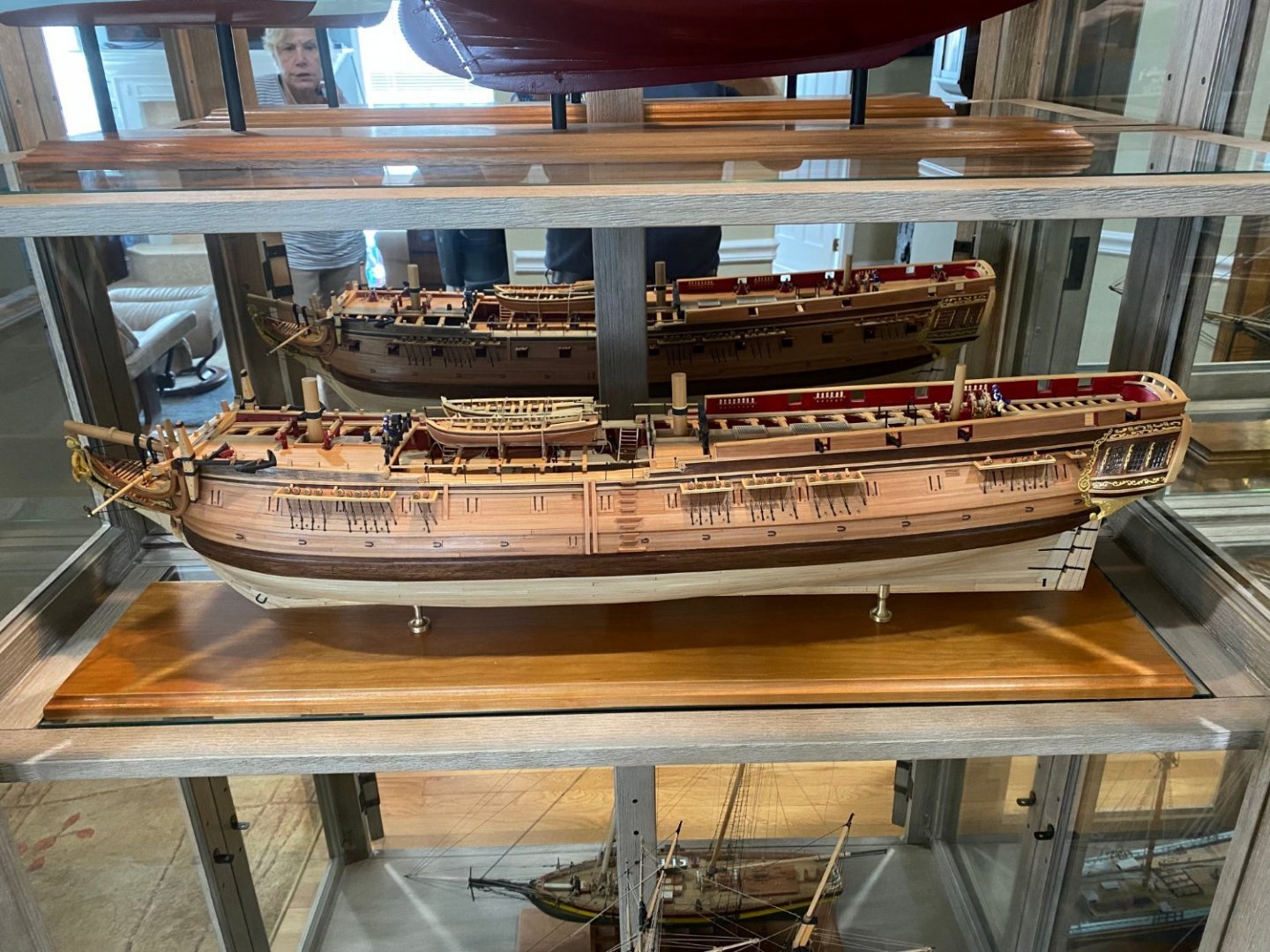
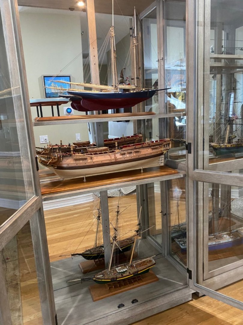
Here are some shots of the finished model both in the shop and in its "final resting place" in the display cabinet in the house. There is room for one more Admiralty model in the current cabinet configuration. After that I will have to "donate" them to my relatives or a deserving charity closer to home.


- 370 replies
-
- 4
-
-
- Model Shipways
- Confederacy
- (and 1 more)
-
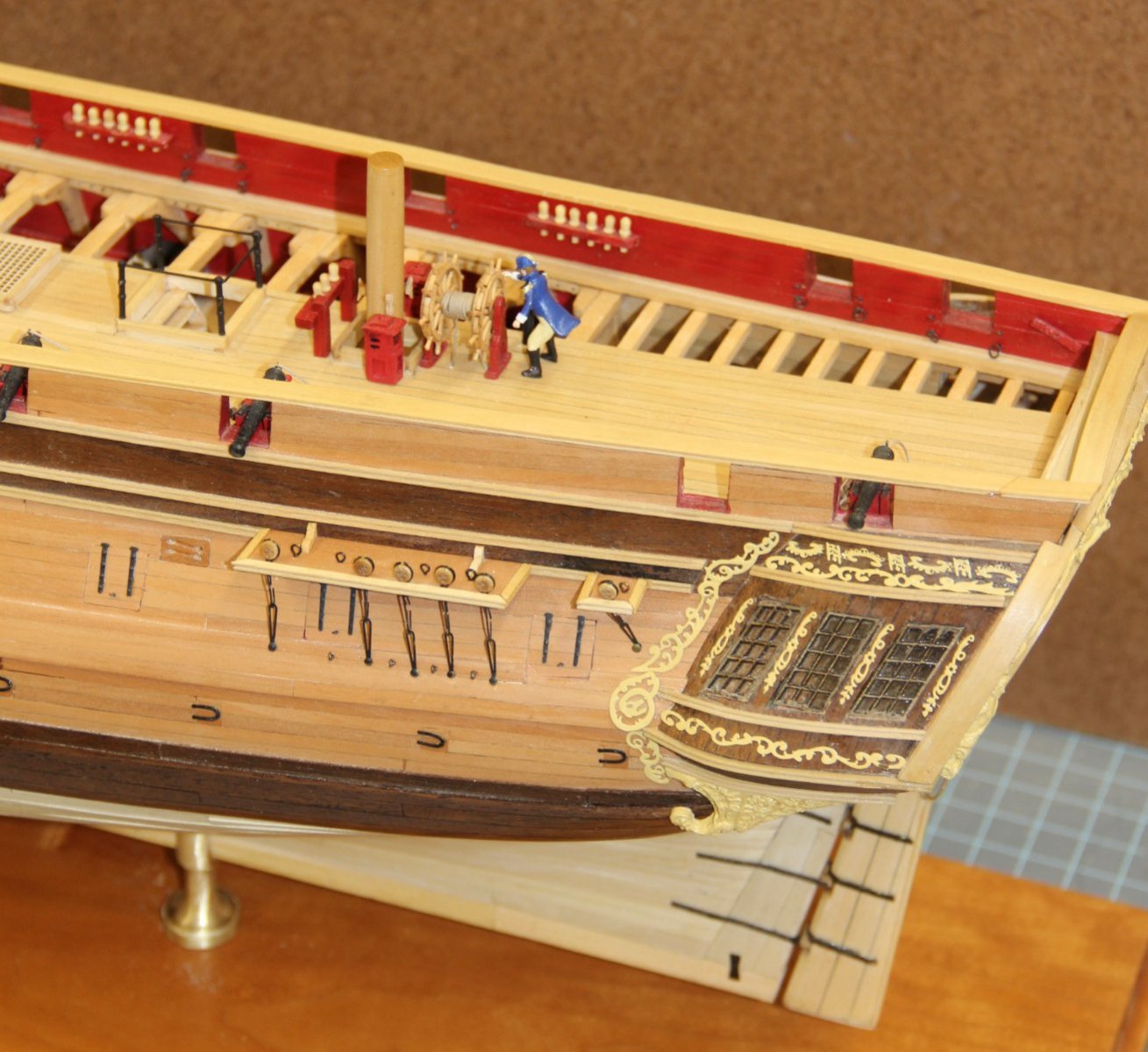
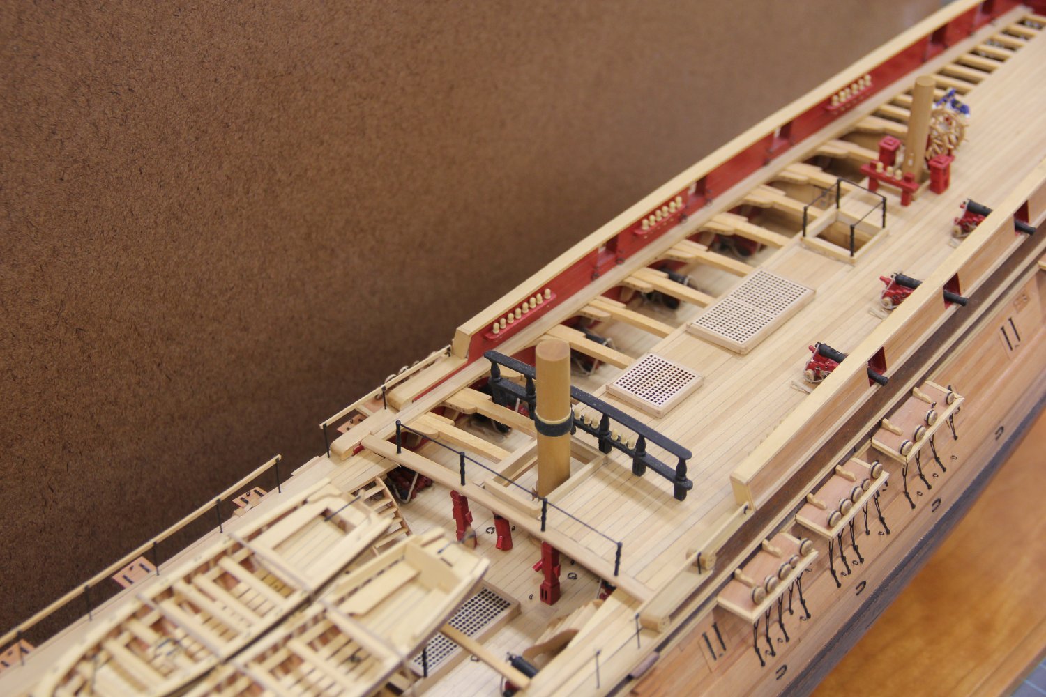
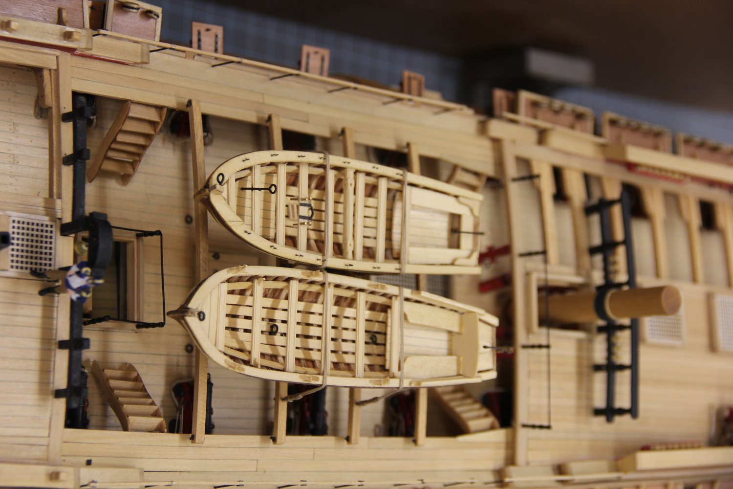
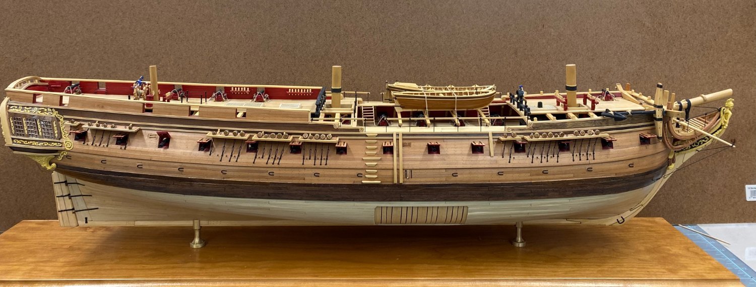
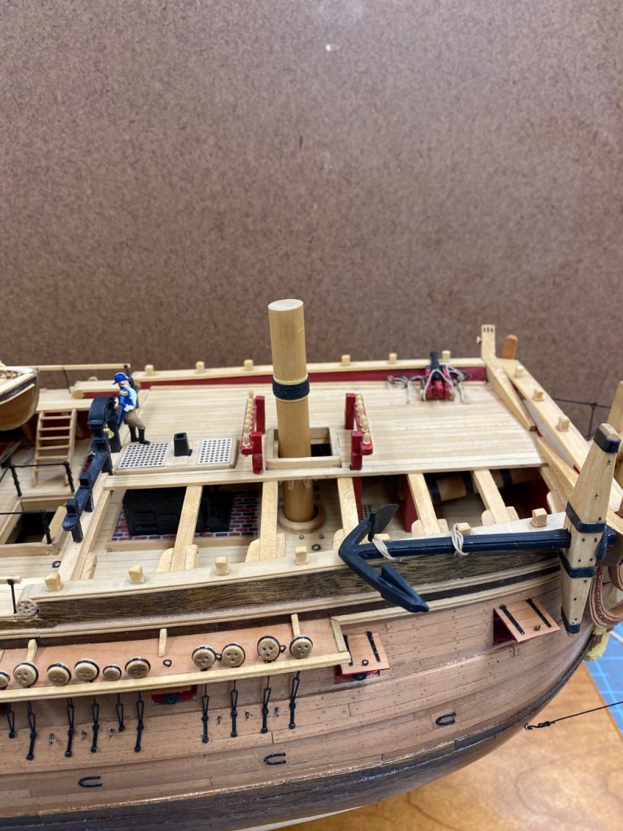
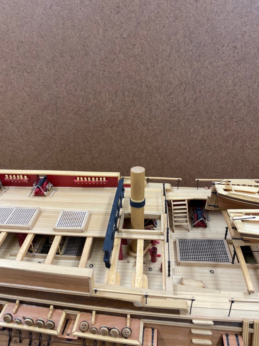
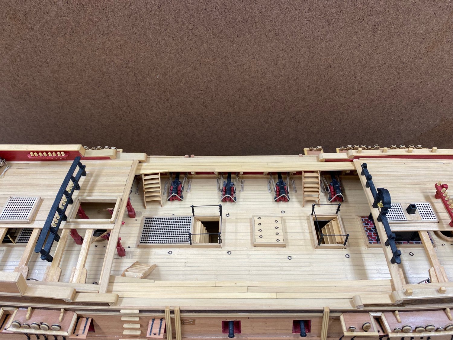
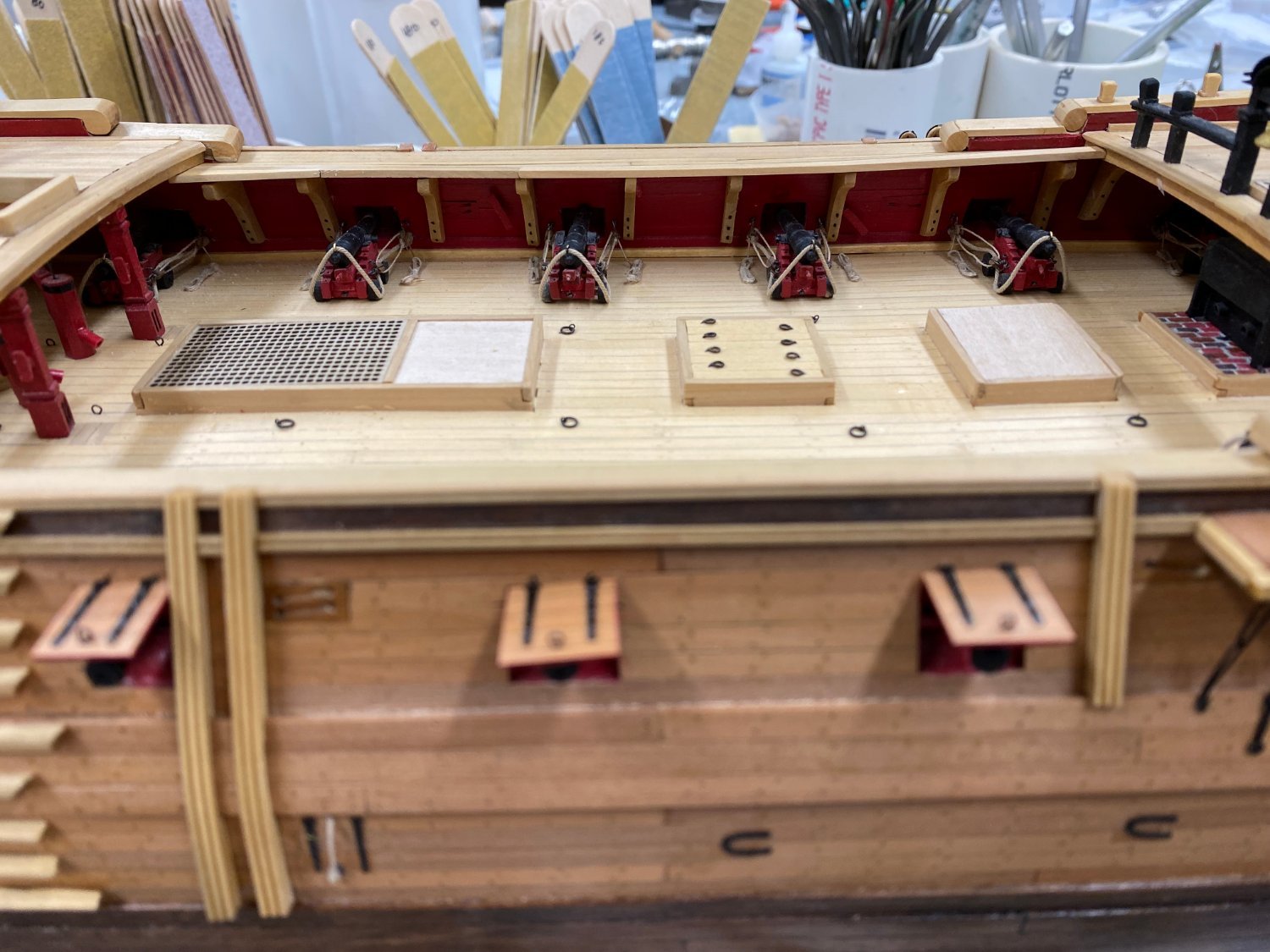
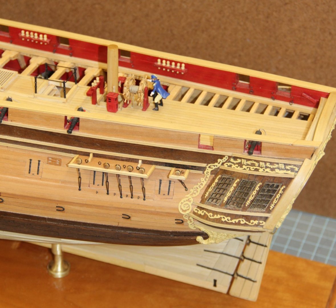
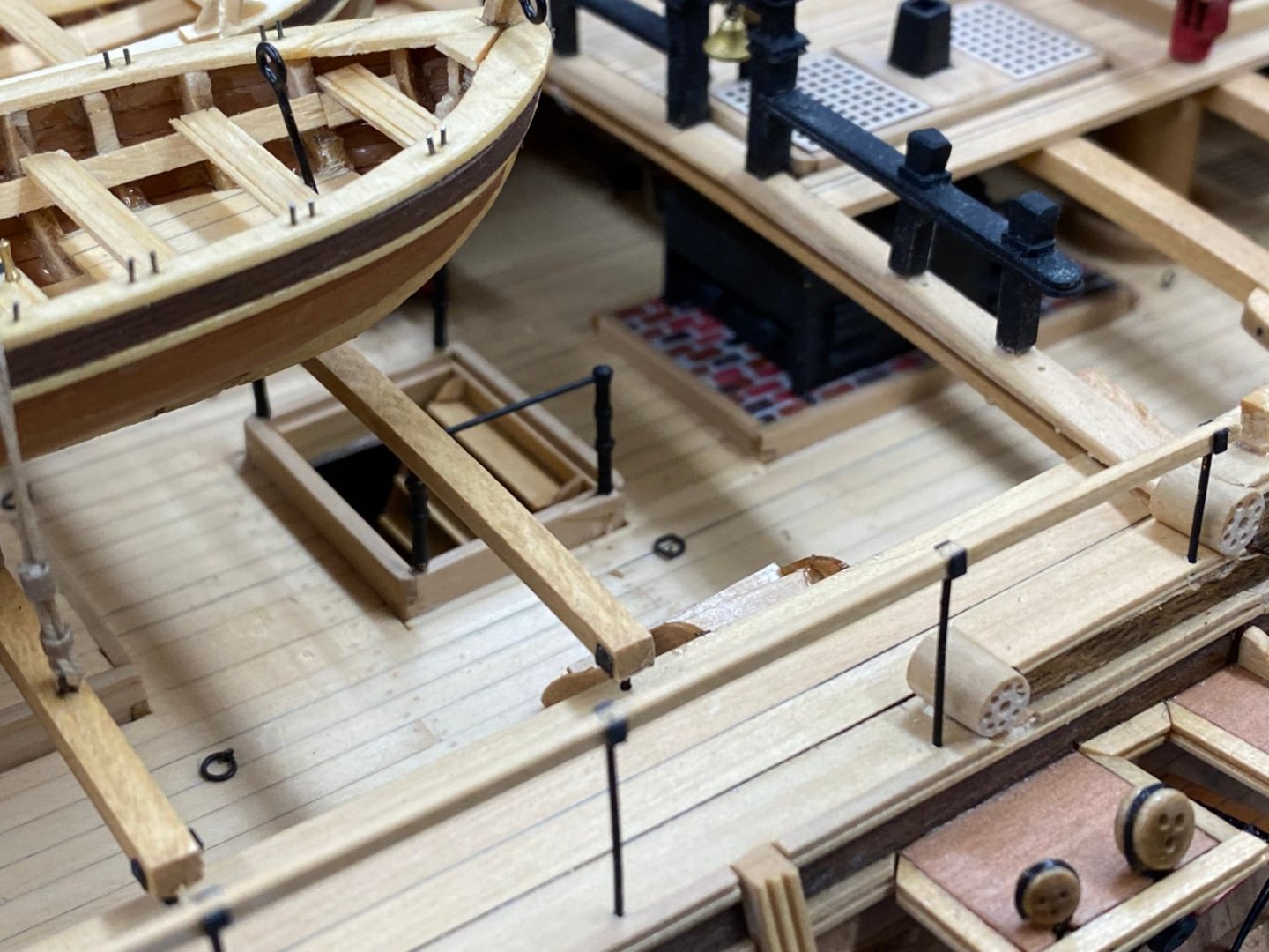
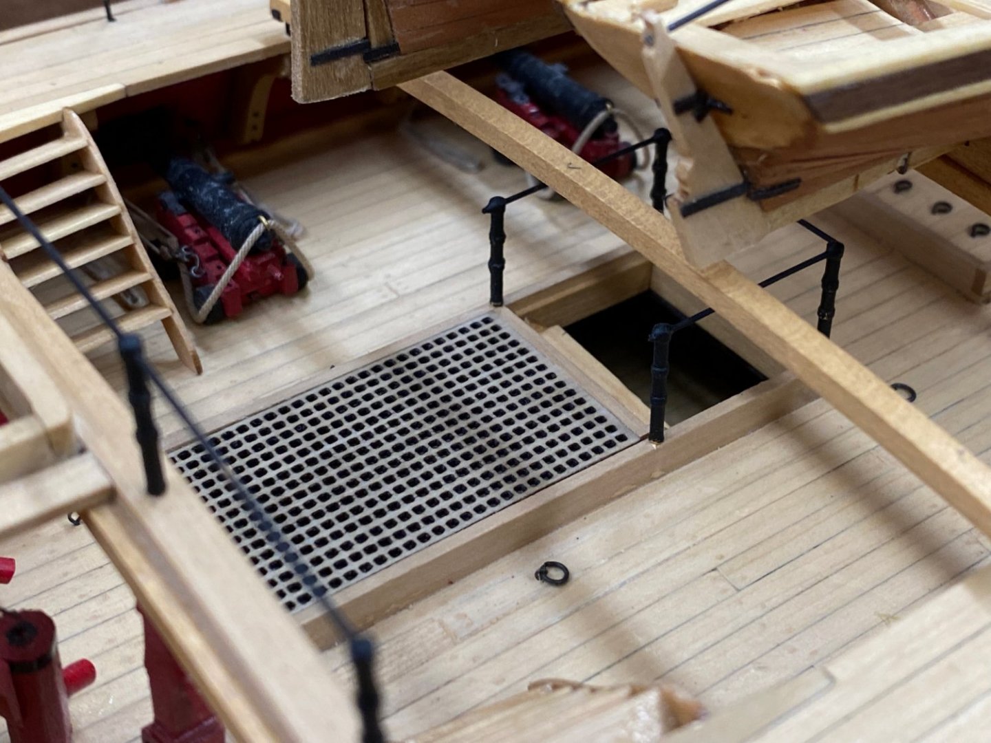
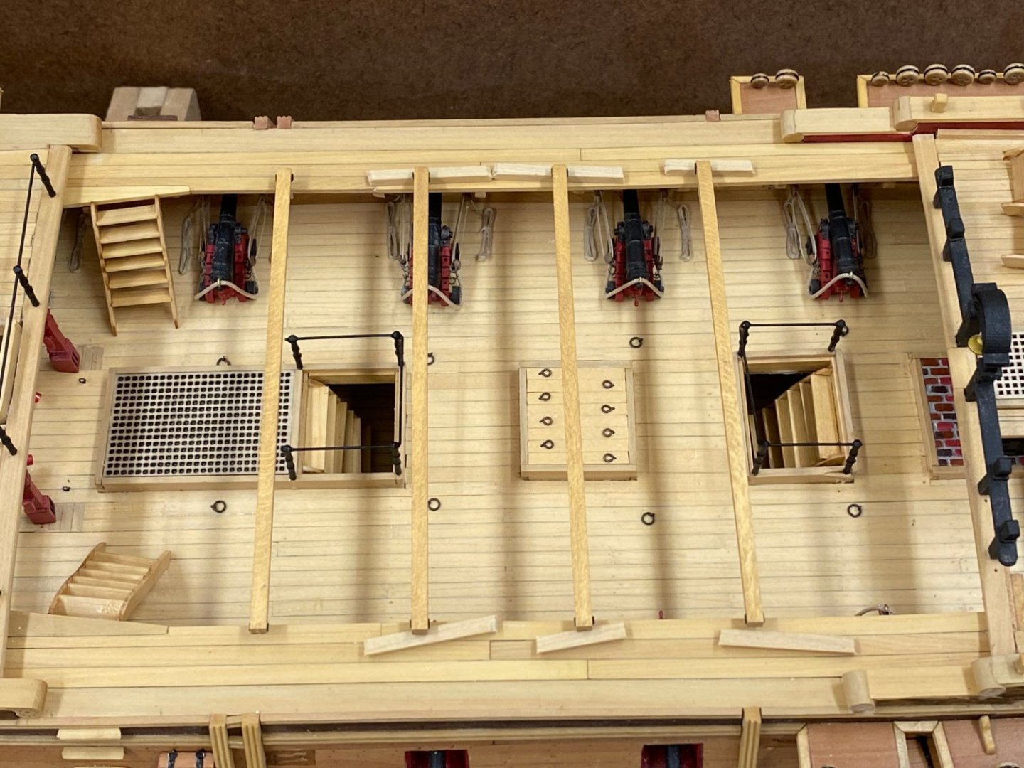
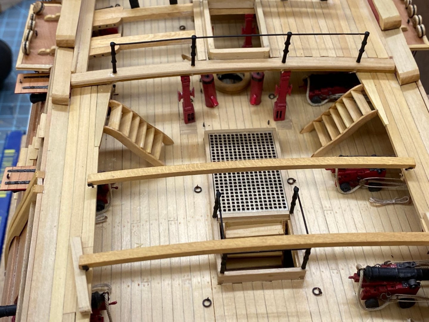
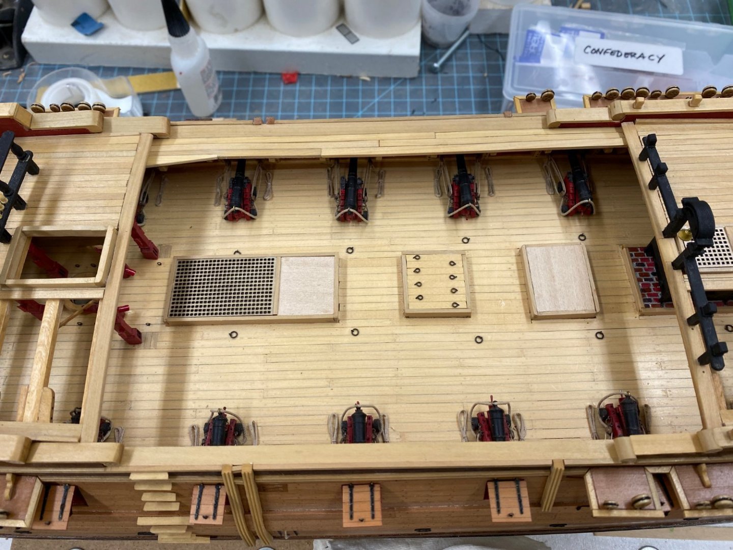
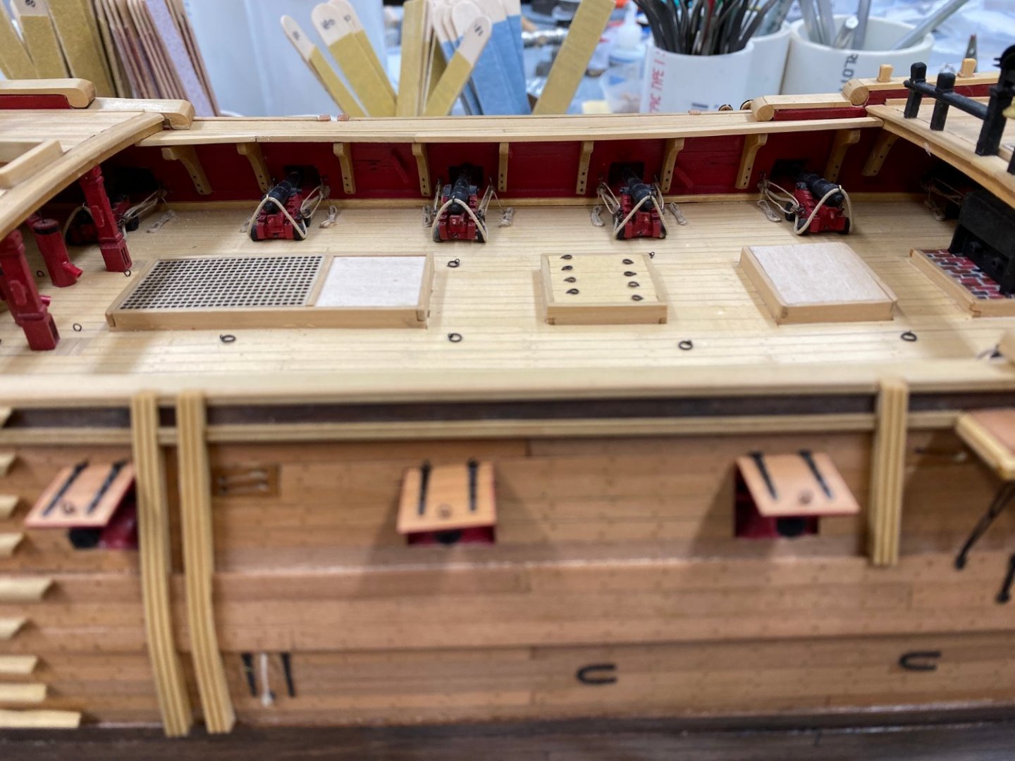
It is FINISHED - I added the "Finished Build" tag to the build log. I guess that is how we "celebrate" these days. Here are some more pictures of the "finished product". My decision to plank over the centerline enough to mount all the centerline equipment means it is harder to see the detail under the forecastle and quarterdeck. On Wenchelsea I may only plank the center so you get a better view of the detail below. Anyway here are some pictures trying to get a view of the gun deck.


- 370 replies
-
- 2
-
-
- Model Shipways
- Confederacy
- (and 1 more)
-
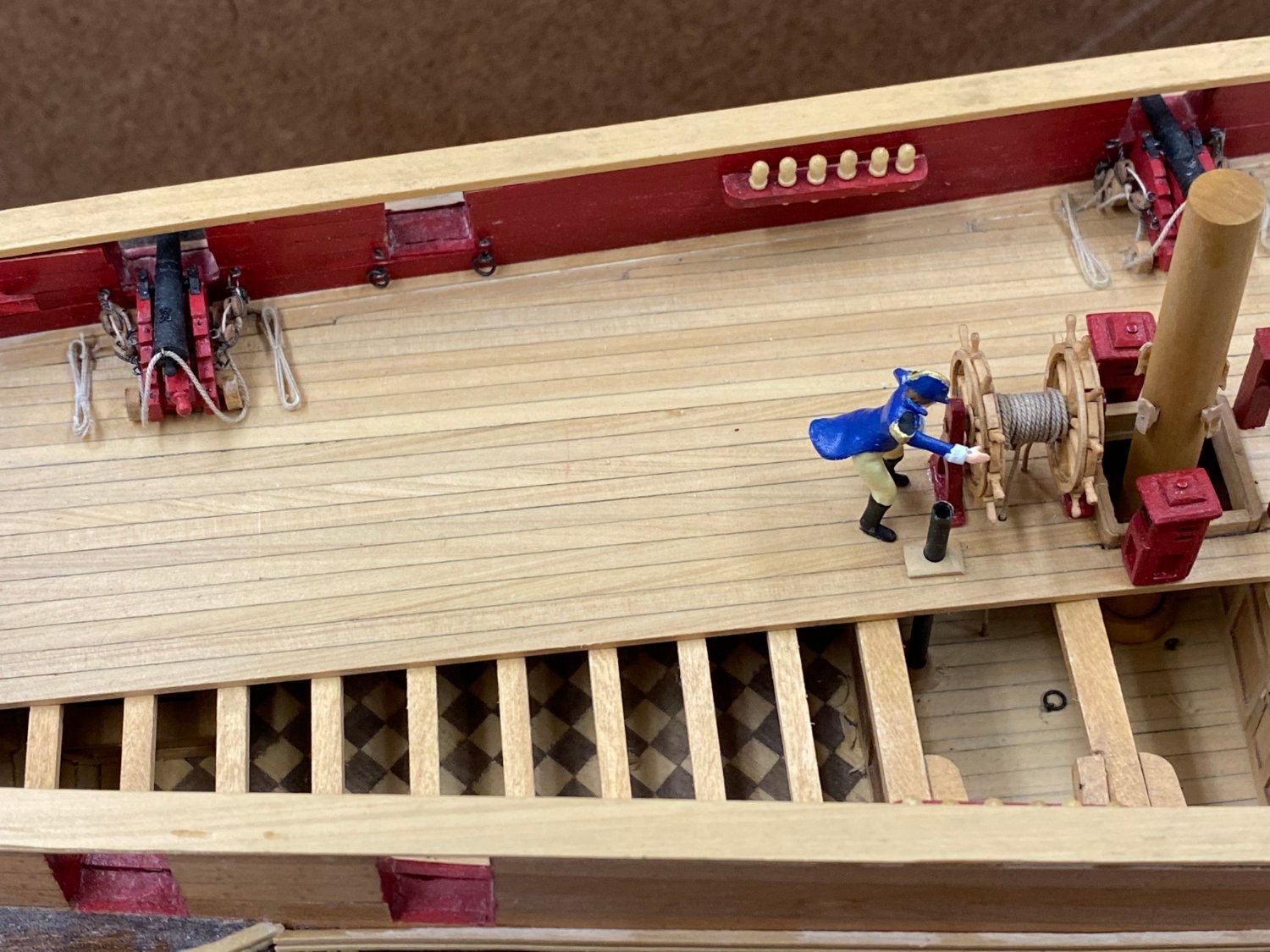
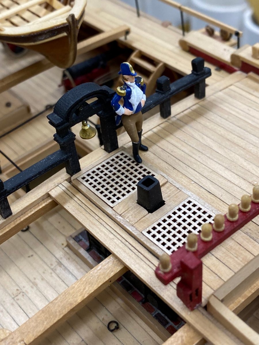
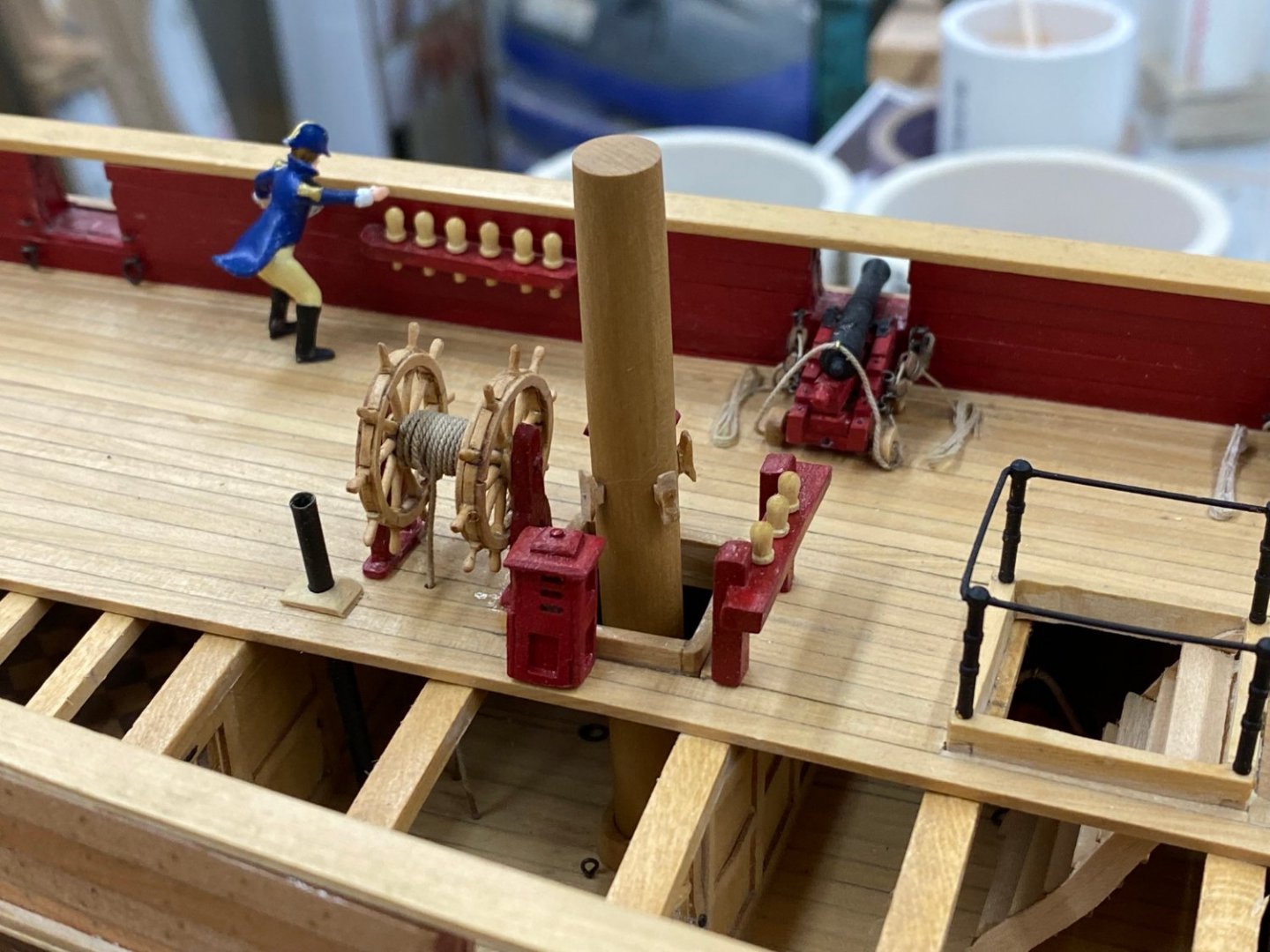
Allan, Thanks for the observation. I will move the figure away from the pin rack so it is not so obvious. Actually these are not the pins that came with the kit. They were smaller and brass (still probably too big) but they got "lost" on the red pin rail and red bulwark so I bought these and justified the size by telling myself this was an Admiralty model and thus meant to convey the overall ship design, not how it would look in actual service. I am going to build the Wenchelsea next and will make sure I use belaying pins that are to scale even though that is also an Admiralty model.
- 370 replies
-
- 1
-
-
- Model Shipways
- Confederacy
- (and 1 more)
-
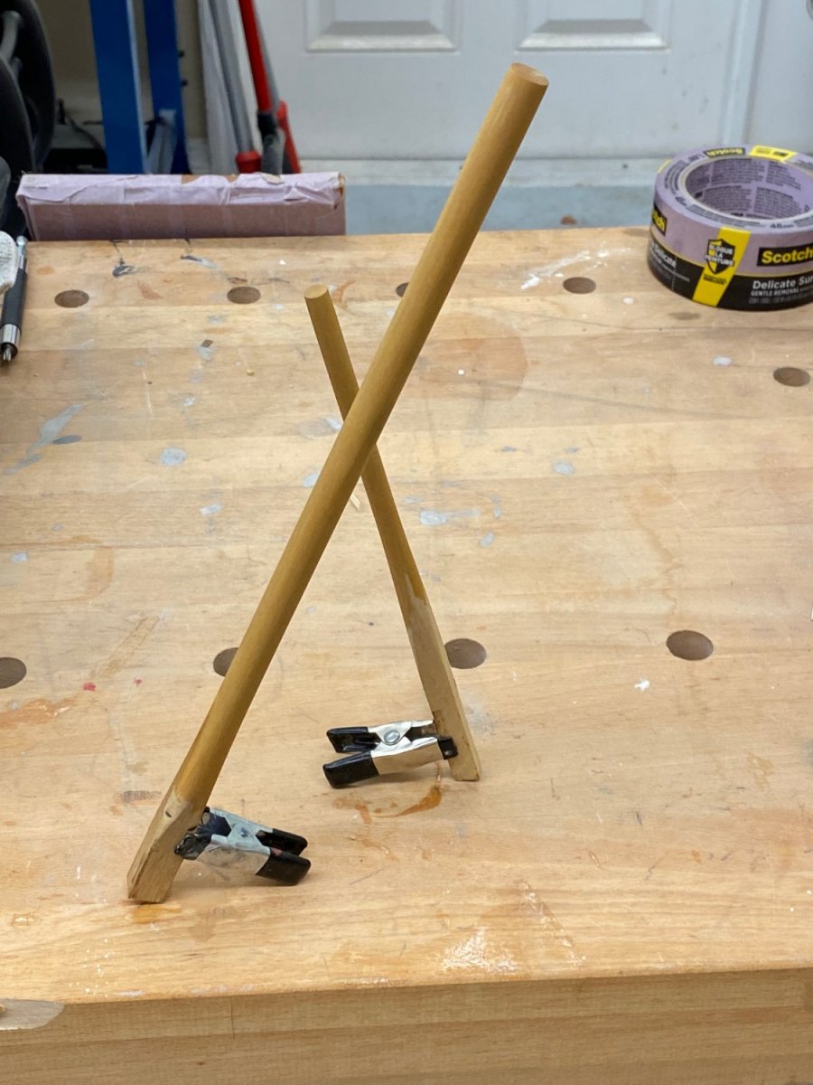
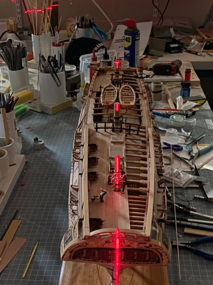
I used the laser level to check the heights of the masts and to make sure they are not sloping from side to side. There does not appear to be a noticeable rack to any mast so I just have to get them straight. Here is the laser in use. It shows the fore mast to be a little tall so before I glued it in I trimmed about 1/8" off the top using the disk sander. So, with one more anchor to lash on and a few drops of WoP on the tops of the masts yet to go the finish line is in sight. I ordered a "mini-vacuum" attachment from Micro-Mark to get a good vacuum on the model before it goes into the display cabinet. So it will be a few more days until I can declare this one FINISHED but once I get the anchor lashed on that will complete the assembly of the Confederacy. Here are the fore and main masts installed. And two shots of the model overall. I will post some more detailed shots when I get it "finish cleaned".


- 370 replies
-
- 6
-
-
- Model Shipways
- Confederacy
- (and 1 more)
-
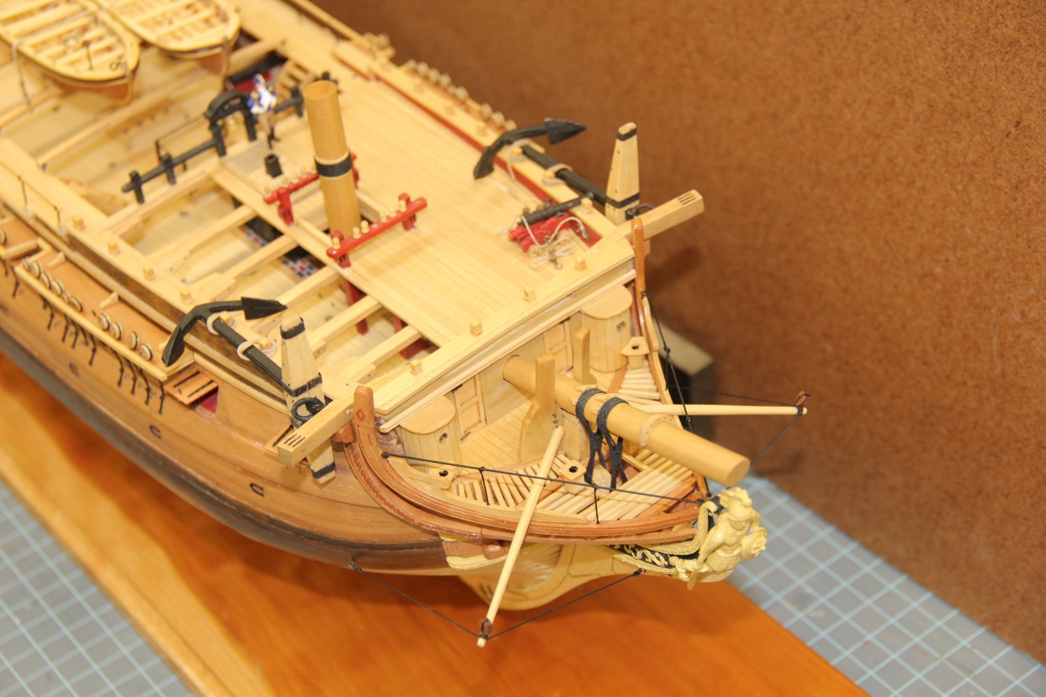
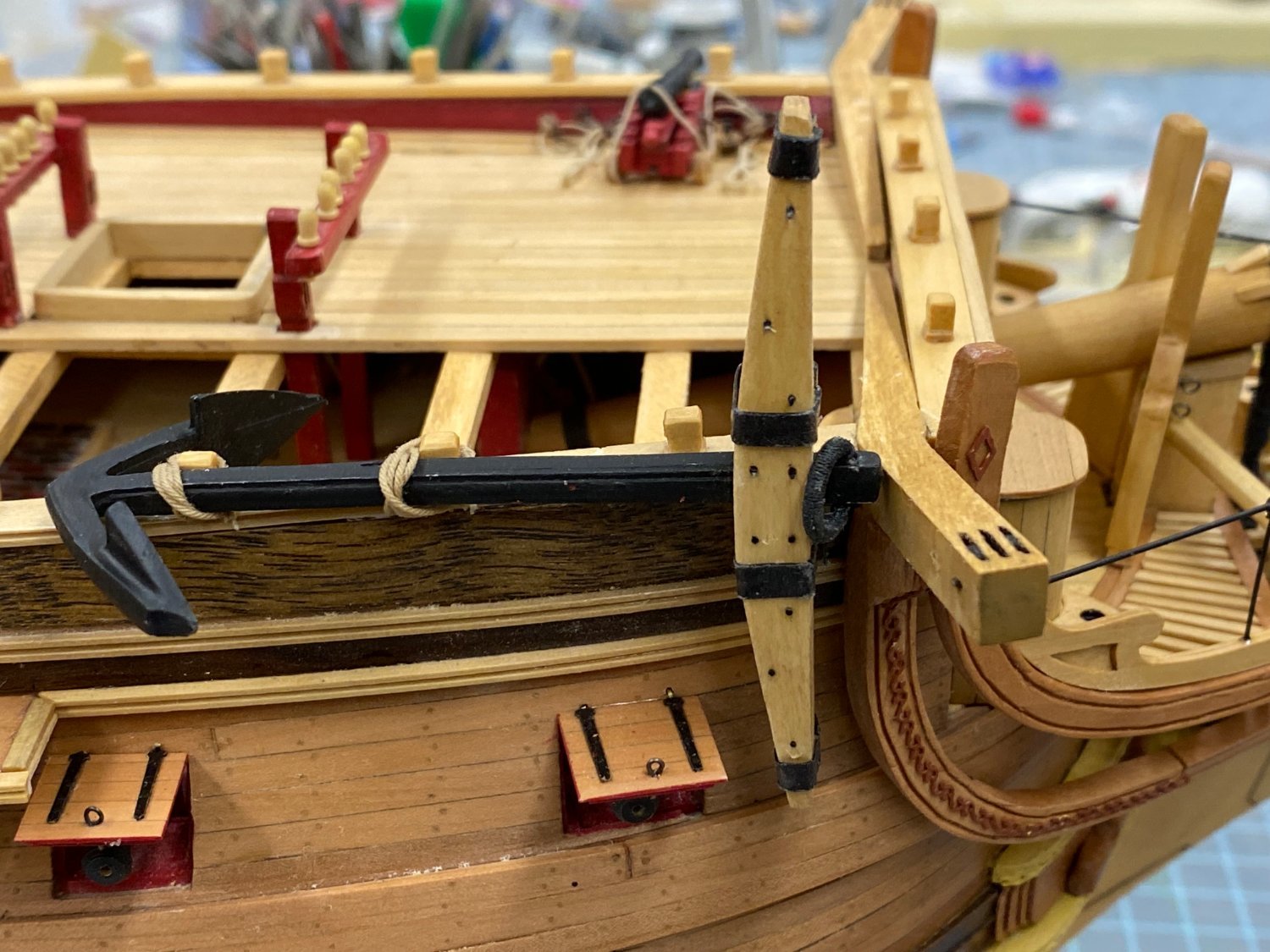
A review of the instructions revealed that I had not accounted for the anchors, which are just lashed to the forecastle rail. I had built the anchors previously except for the serving on the one of the anchor rings. So I mounted the one that was complete and am putting the serving on the ring of the other. Here is the starboard side anchor in position. I had also, for the first time included some scale figures on this model. I used the figures available thru the NRG Store and IMHO they turned out pretty well. Here is one mounted on the forecastle. I got the cleats mounted on the mizzen mast stub and have it sitting in position but not secured. I need to get the main and fore mast stubs completed and then try and get them all the same height. You can see the other figure in the background. I am not sure what the final position for this one should be as the pose looks a bit more interesting than the one forward. The "END" is in sight!!!


- 370 replies
-
- 4
-
-
- Model Shipways
- Confederacy
- (and 1 more)
-
Mounted on display board. I drilled holes for the stand-offs in the center keel unit. I do. not have any stand-offs that have a notch wide enough for the Confederacy keel so I using flat topped ones and the model sits on the pedestals with a pronounced starboard list. Not sure what to do but order some stand-offs with a 1/4" wide notch. As a temporary measure I am putting together the display stand that comes with the kit. Mast stubs are all that is left pending a review of the instructions and pictures to see if I missed something (important).

- 370 replies
-
- 4
-
-
- Model Shipways
- Confederacy
- (and 1 more)
-
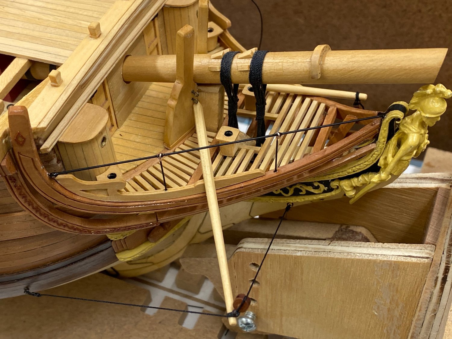
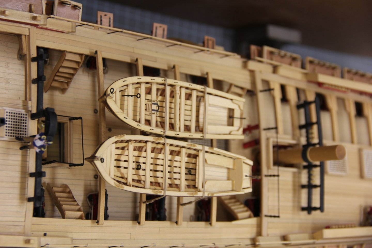
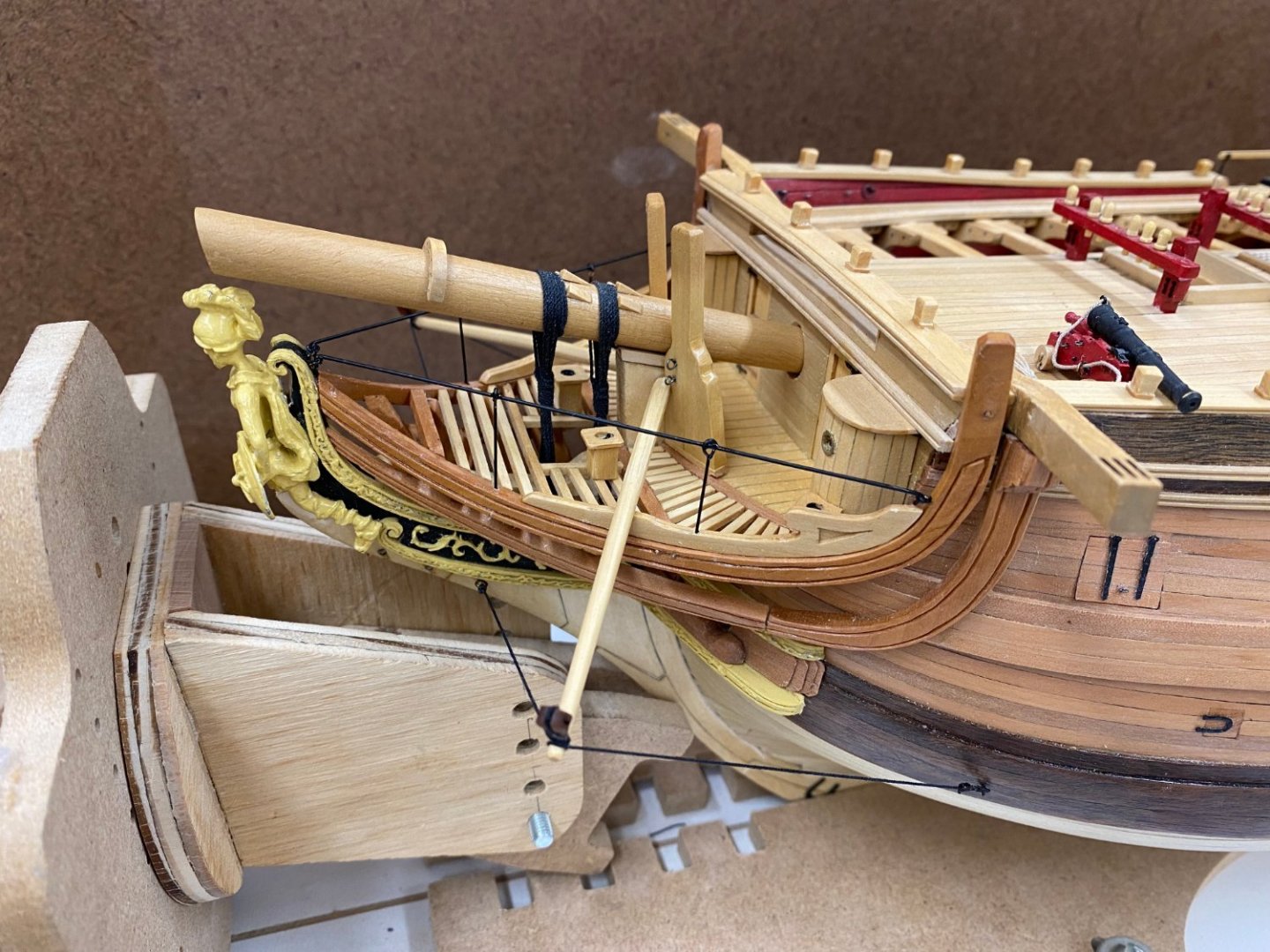
Port side boomkin and birth rail complete. Pinnance mounted Port side waist rail and mounting on display board are next. Then the stub masts and COMPLETE!!!
- 370 replies
-
- 5
-
-
- Model Shipways
- Confederacy
- (and 1 more)
-
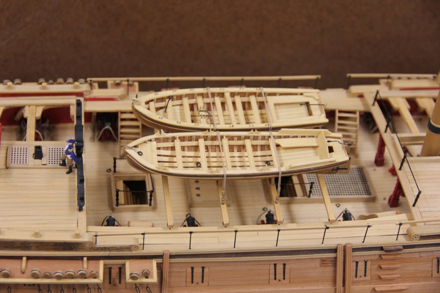
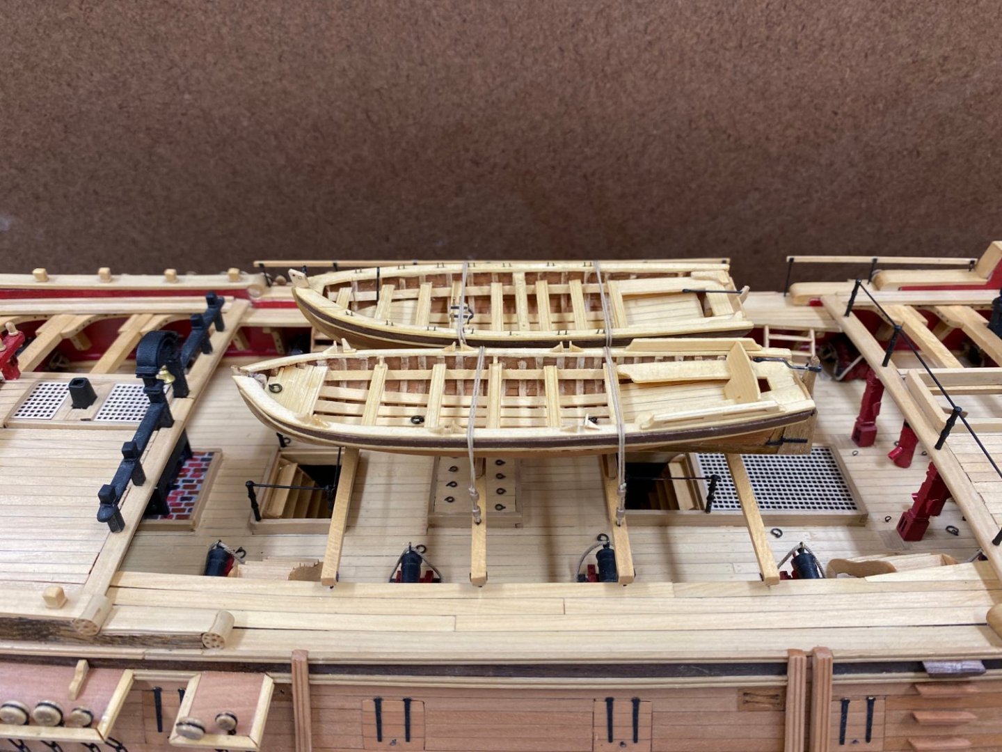
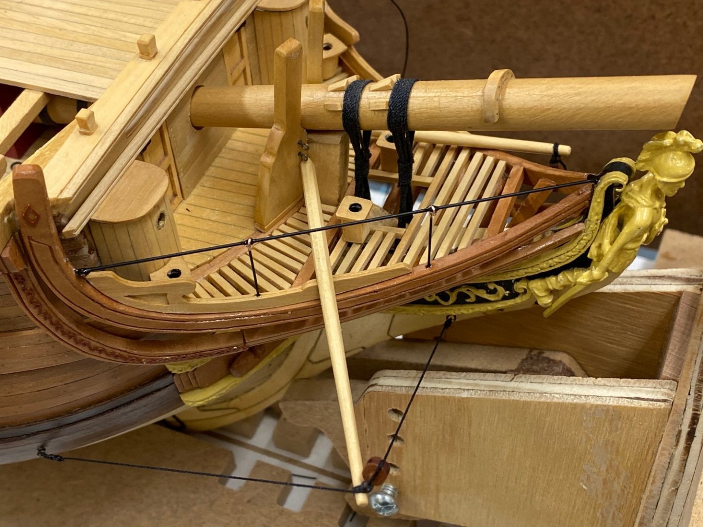
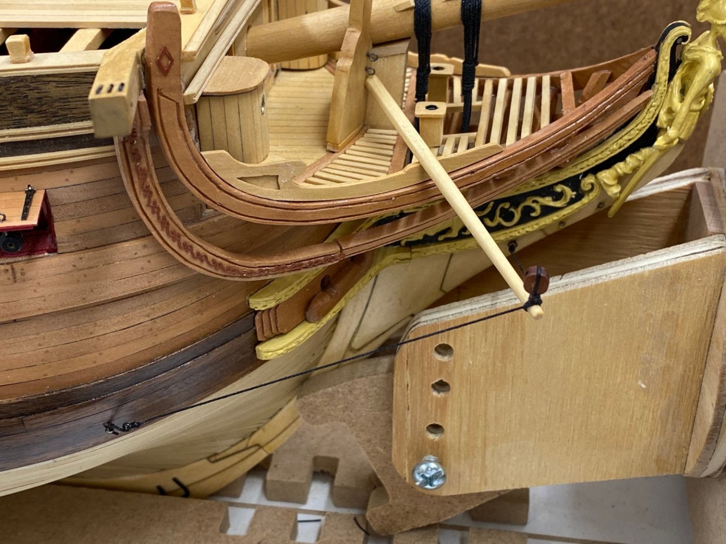
Since I already assembled the ship's boats it is time to get them mounted. Here is the longboat mounted and secured per the instructions. The securing lines for the pinnance can be seen in the background. I will probably do that before I install the waist rail on that side since I almost damaged the one on this side getting the securing lines secured. Somehow in my relief to have completed the details in the bow I manged to bypass the "birthing rail". I used a length of .025" music wire for the rail and fashioned two stanchions from .020" phosphor-bronze wire to replace the photo-etched parts provided. I could not make a loop in the end smaller than the one on the photo etched stanchion. Here is the completed starboard side of the bow except for some touch up painting once the CA I used to secure the wires to each other is completely dry.
- 370 replies
-
- 2
-
-
- Model Shipways
- Confederacy
- (and 1 more)
-
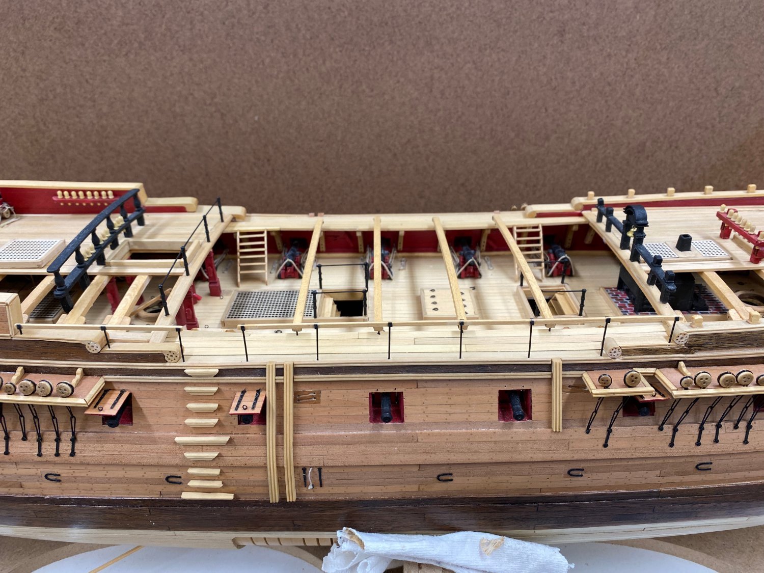
Starboard side waist railing completed. I decided that I would not use the provided photo etched stanchions. I generally do not like flat photo etched parts substituting for what would be round section items. At this scale it is probably hard to tell but "I will know". I started with 1/16" X 1/16" boxwood strips. I marked where the stanchions would go using the actual model instead of the plans. I then drilled a shallow (not through the wood) hole at the locations where the stanchions will be located. I took particular care to get the hole in the center of the strip. I made three sets of railings to accommodate a potential failure (should probably have made four). Once the holes were drilled for all the stanchions (two sections on each side) I ran the 1/16 X 1/16" strips (carefully) through the thicken sander and reduced the width to about .04" - more than the 1/32" (.0313") called for in the plans but about as narrow as I was willing to go and still have a hole rather than a groove. For attachment I used a similar scheme to the skid beam fittings. Small (hopefully approx 1/32" wide) pieces of black laserboard were glued to each side of the railing and then the railing was used to mark the locations of the holes on the model. I pre-painted .025" phosphor-bronze wire flat black and used thin CA to glue appropriately sized pieces into the railing. Now the fun, getting the stanchions into the holes in the deck while not distorting the railing enough to cause one of the areas with a stanchion to fail. I got the forward section in okay but the shorter aft section failed while I was maneuvering it into position and adjusting the heights. Here is the starboard side: Now on to the port side.

- 370 replies
-
- 2
-
-
- Model Shipways
- Confederacy
- (and 1 more)
-
Starboard side boomkin rigged. I used a 5mm Model Shipways swiss pear block and .5mm black rigging thread from Ropes of Scale. I am not sure I got the required downward slope but I can't find the boomkin on the drawings except in plan viewso I have only the instruction pictures to work from. I made my own boomkins in Boxwood but bent them to match what was provided in the kit. I need to reorient the model to work the port side but I have a few other details to work on the starboard side.For instance, I need to replace the gun port doors for position 5 and 6. They are in a vulnerable spot and don't have any protection from the channels so they both came adrift while I was working the gangways. I would suggest that at a minimum there two not be installed until pretty much everything else is done.
- 370 replies
-
- 5
-
-
- Model Shipways
- Confederacy
- (and 1 more)
-
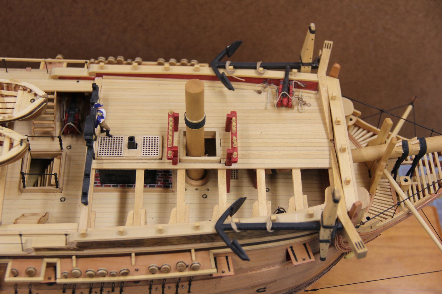
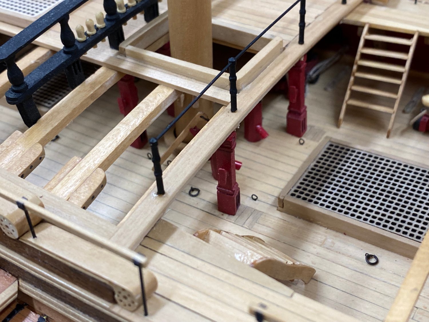
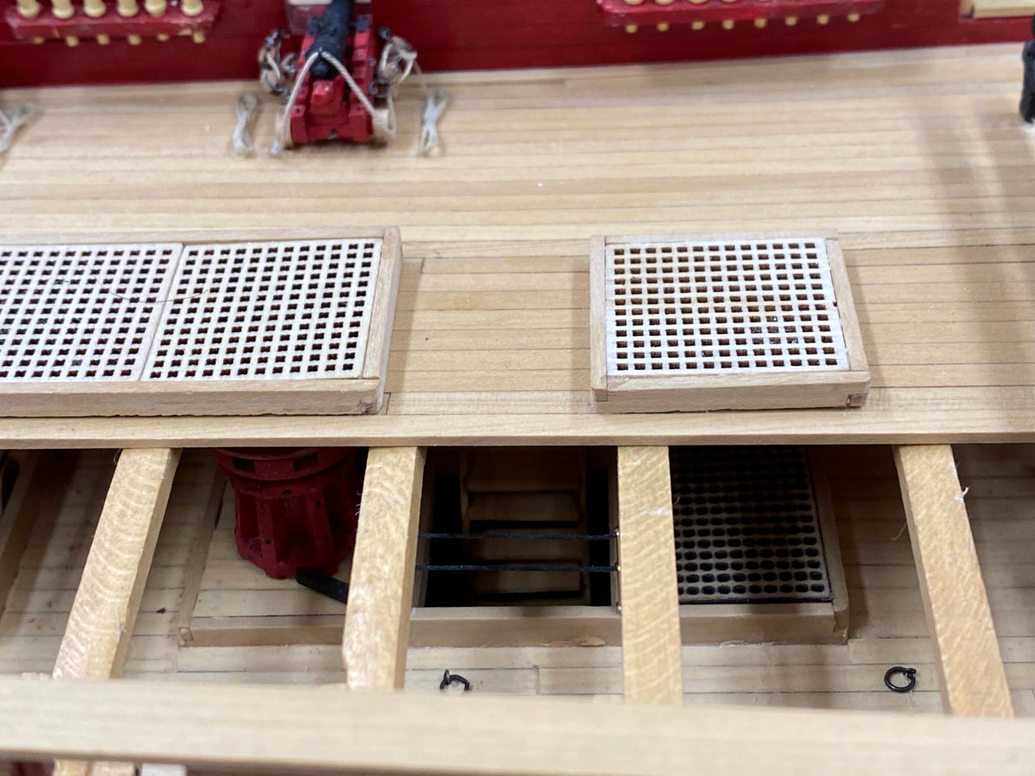
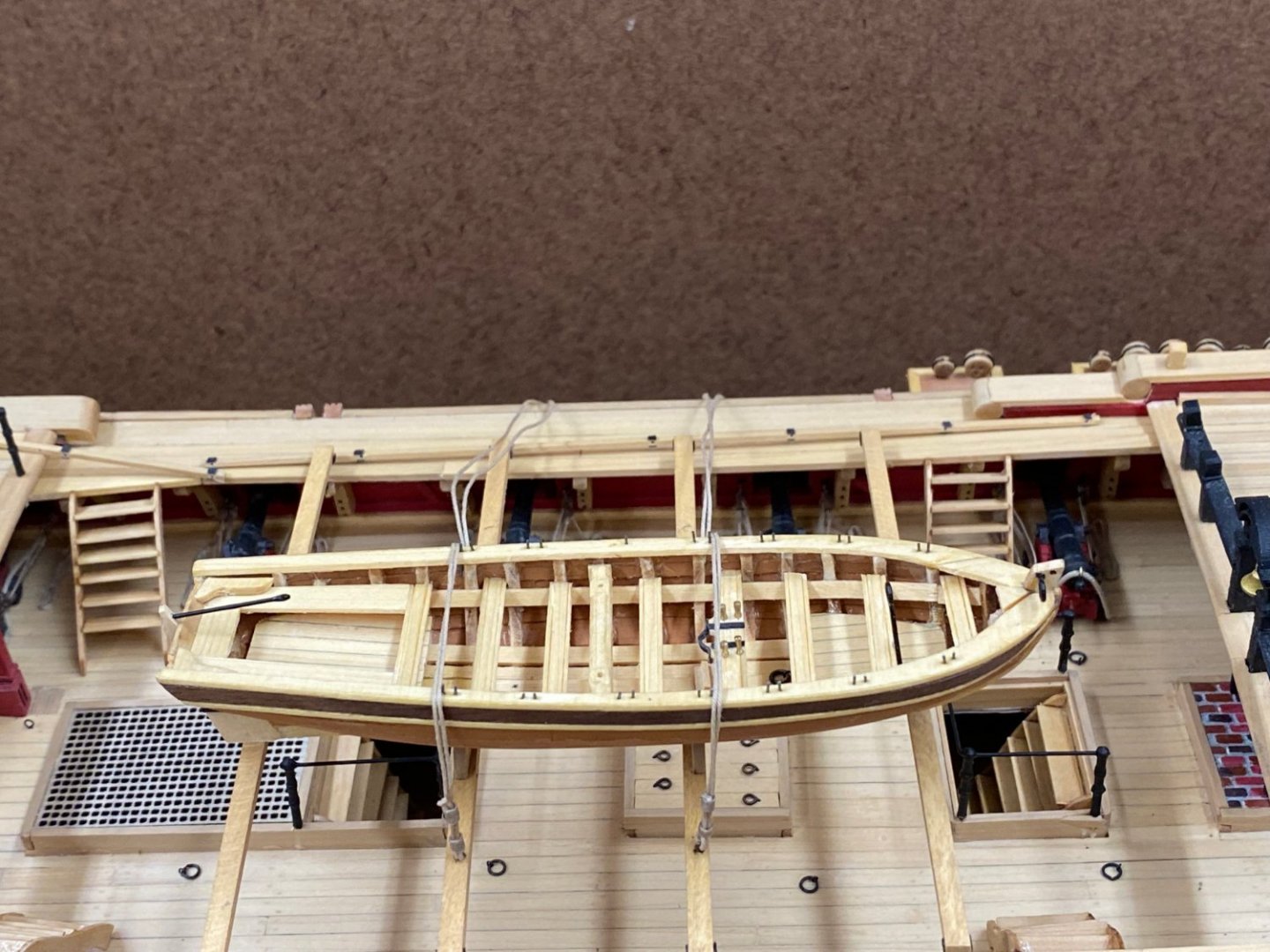
The first (aft) skid beam is in place and the other three are in place. I used a piece of 3/32" scrap to make a spacer to get the 3/32" clearance between the beam end and the deck. Although the instructions warn about making sure the beams are square and evenly spaced IMHO with the boats in place this will not be apparent unless they are badly misaligned. I located one side by the plans and then replicated the spacing from that side to the other to locate to holes for the pins on that end. One of them ended up pretty close to the edge of the planking but I manged to keep from splitting the plank by using a rattail file to carefully enlarge the hole to get the pin to slide in. I had to remove the two forward ladders to the gnagway since where I had them they were going to be too close to the skid beams. Luckily I got them out without damage. Will reinstall when the skid beams are secure. Here are the skid beams as I secure the other three. You can see the spacers at each end of the three forward beams. While waiting for the glue to set on the laserboard "brackets I installed the quarterdeck railing. Same stanchions and rail as are on the companionways.
- 370 replies
-
- 3
-
-
- Model Shipways
- Confederacy
- (and 1 more)
-
Looking forward to the masts I utilized my "poor mans lathe" (aka Drill Press) to turn some square boxwood stock into 5/16" and 7/16" dowels for the mizzen, main and fore mast stubs. After a first coat of poly they await cutting to size and the accessories (cleats and woodlings). The second gangway has been completed, both sides have received a coat of WoP, and the ladders (assembled previously) and the railings around the companionways have been installed. Next up the skid beams, waist railing and the quarterdeck railing. This time I super glued phosphor-bronze wire into the extra holes in the stanchions and filed them smooth before painting - not sure it was worth the effort but...


- 370 replies
-
- 3
-
-
- Model Shipways
- Confederacy
- (and 1 more)
-
Port side gangway complete. Deck needs a bit of sanding a WoP but other than that I think it came out pretty well. I simulated (holes filled with wood putty) treenailing the gun deck but (IMHO) the appearance was not worth the effort so I have neglected that on the quarter and fo'c'sle decks so to be consistent I will not do the gangways either.
- 370 replies
-
- 2
-
-
- Model Shipways
- Confederacy
- (and 1 more)