DONATION DRIVE - SUPPORT MSW - DO YOUR PART TO KEEP THIS GREAT FORUM GOING!
×


cdrusn89
-
Posts
1,915 -
Joined
-
Last visited
Content Type
Profiles
Forums
Gallery
Events
Everything posted by cdrusn89
-
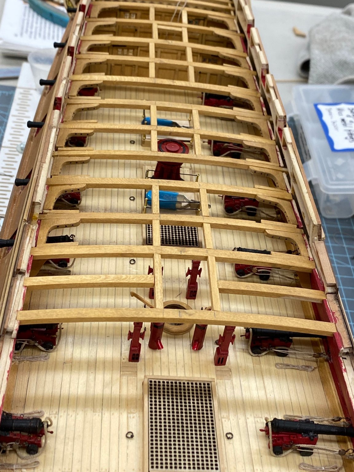
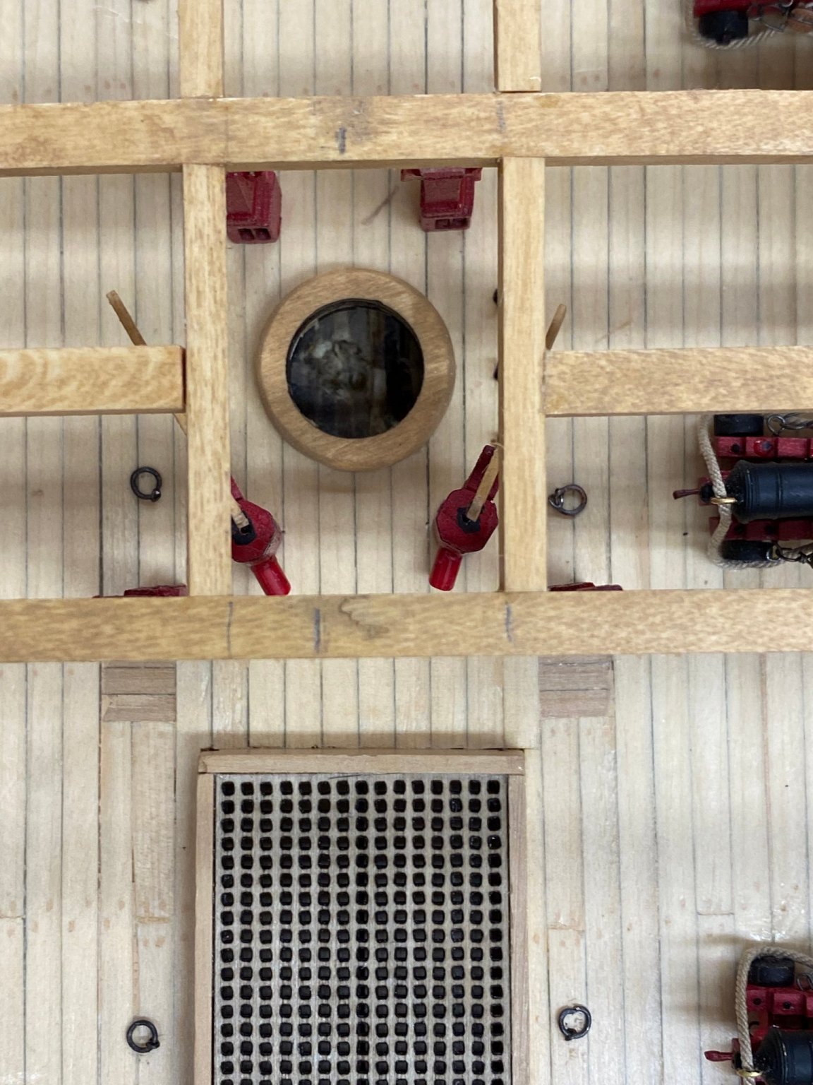
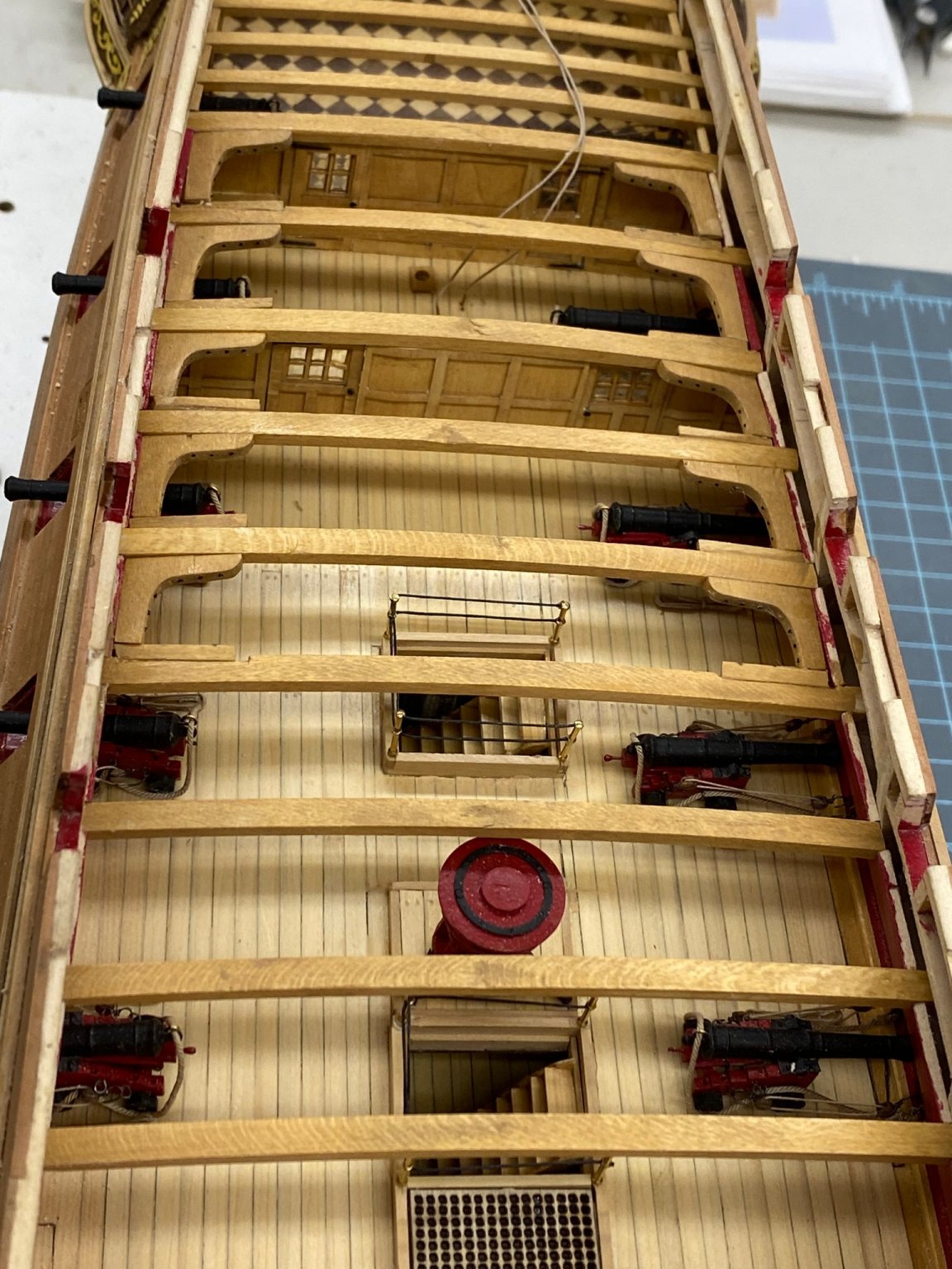
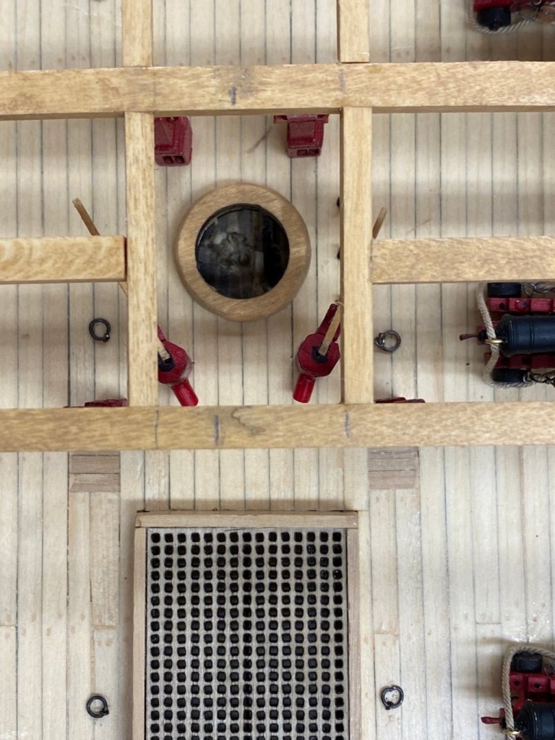
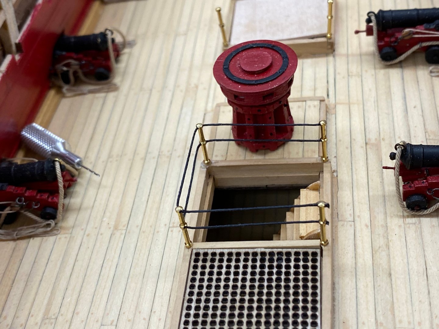
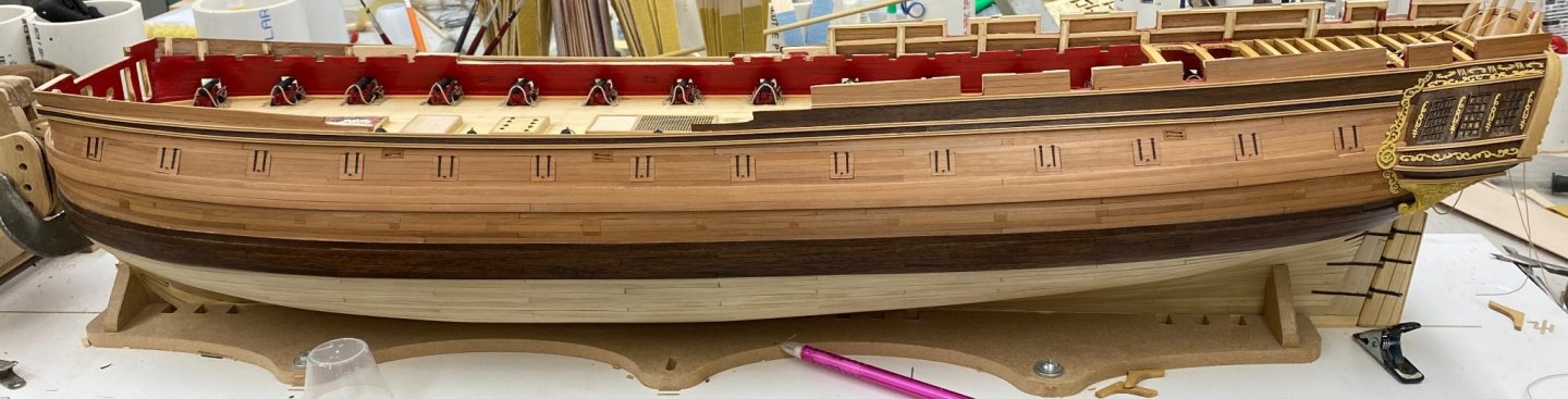
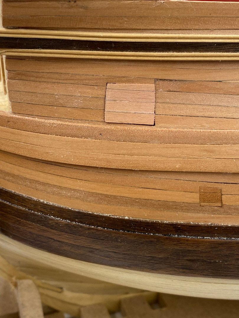
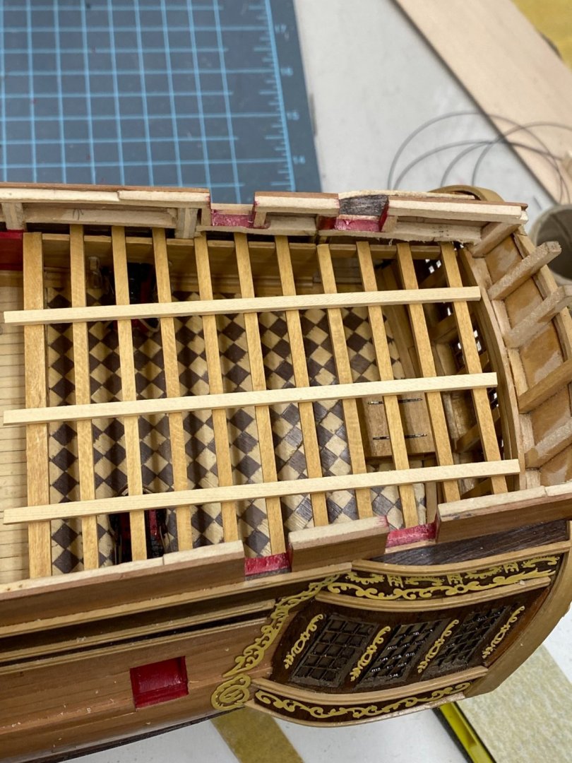
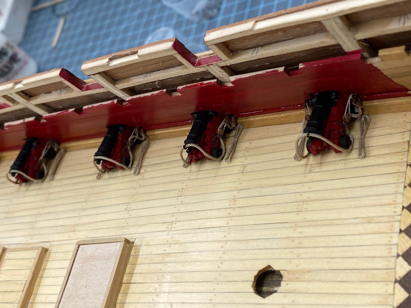
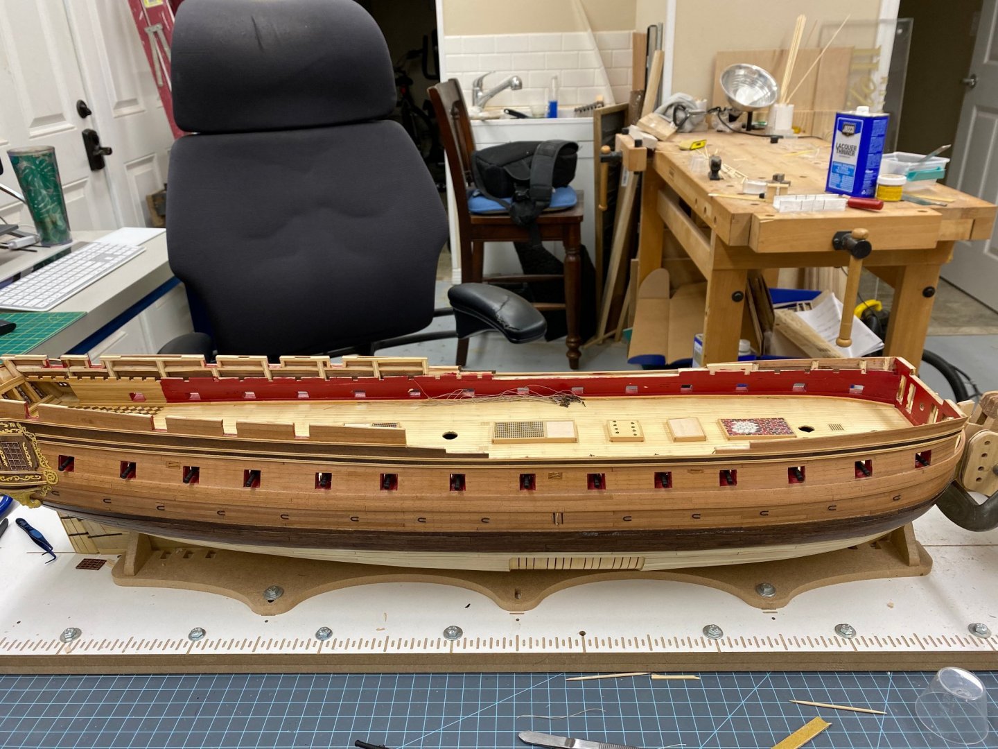
 Quarter deck framing completed (well, almost - I have the knees on the final two beams to complete). I even remembered to put the eyebolts in behind the guns. If I waited any longer it might have been a bit more difficult. I ordered more burnished split rings (3mm size) as I am reluctant to use the brass ones I have as my luck getting them to stay black (or even black-ish) does not inspire confidence. When it came to the carlings I took the coward's way out and thinned the 1/8" X 1/8" stock to 1/8" X 3/32". Besides, I think all of this is covered up by the quarterdeck decking unless you were planning to leave that off (which I am not). So here is the overall view. And a close-up of the main mast coat area.
- 370 replies
-
- 4
-

-
- Model Shipways
- Confederacy
- (and 1 more)
-
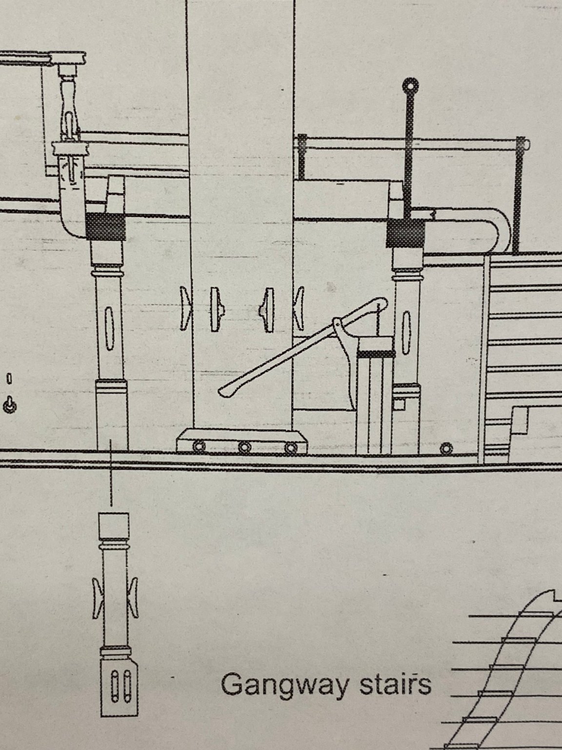
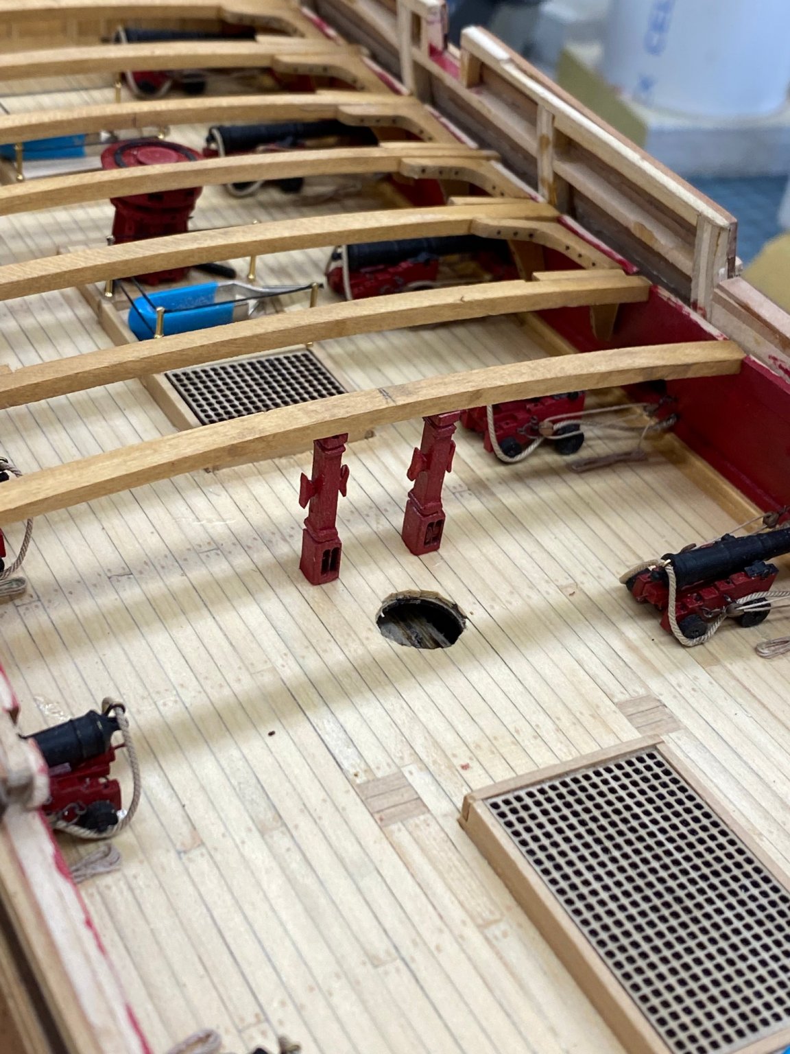
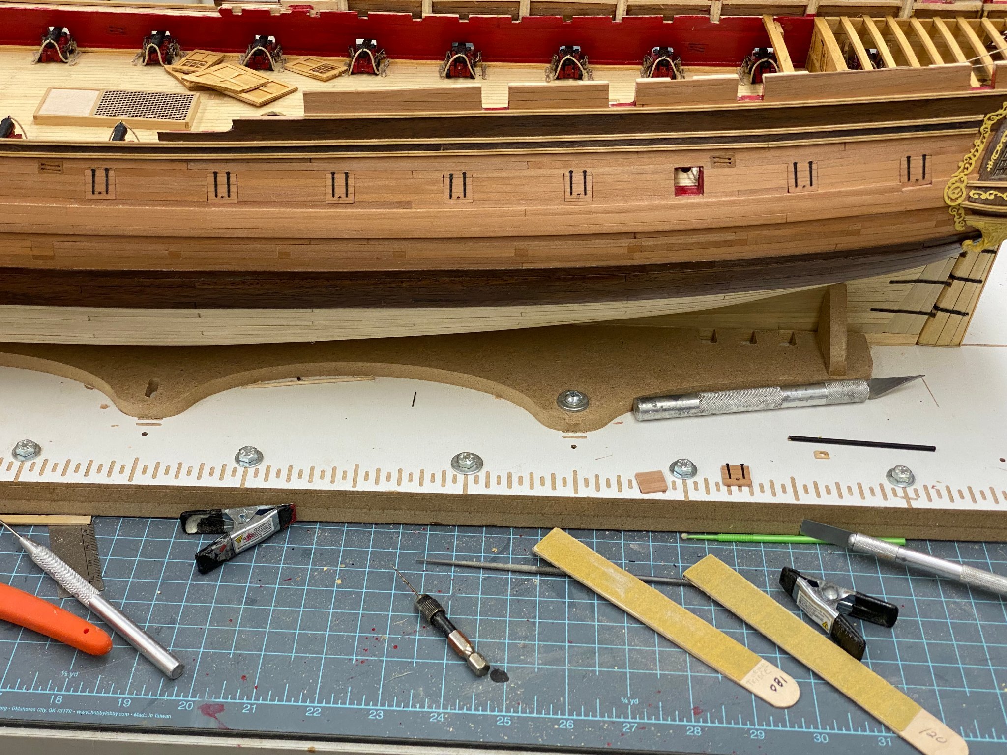
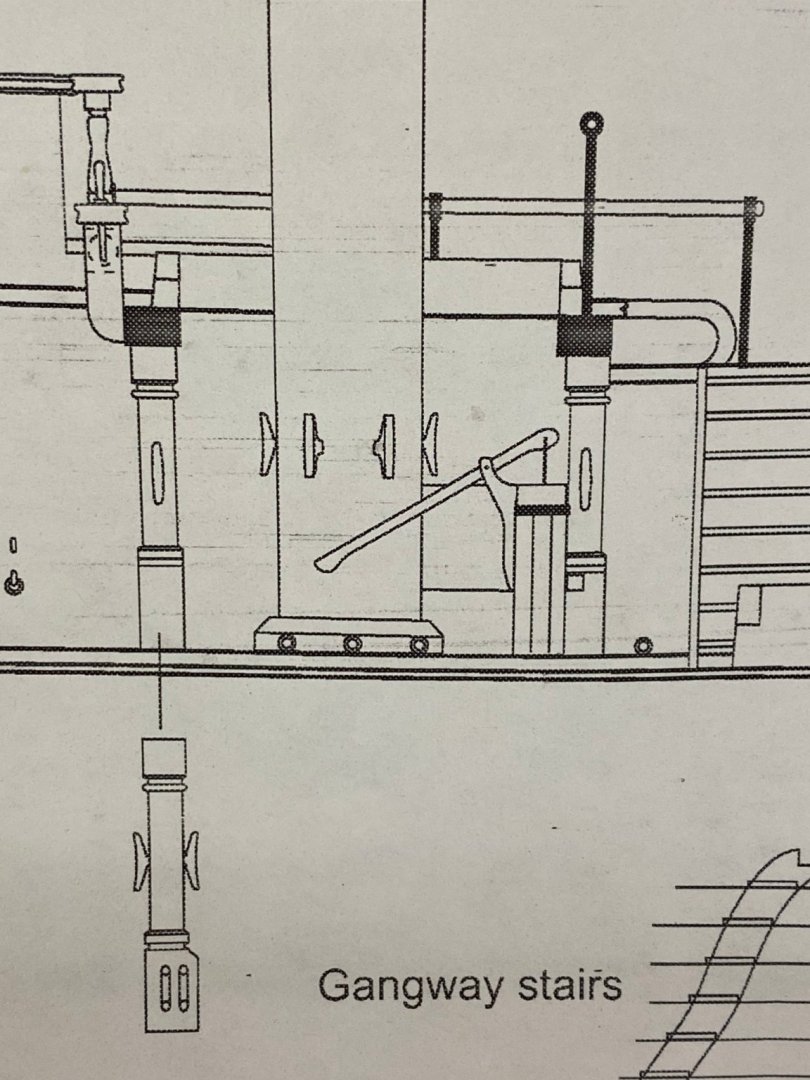
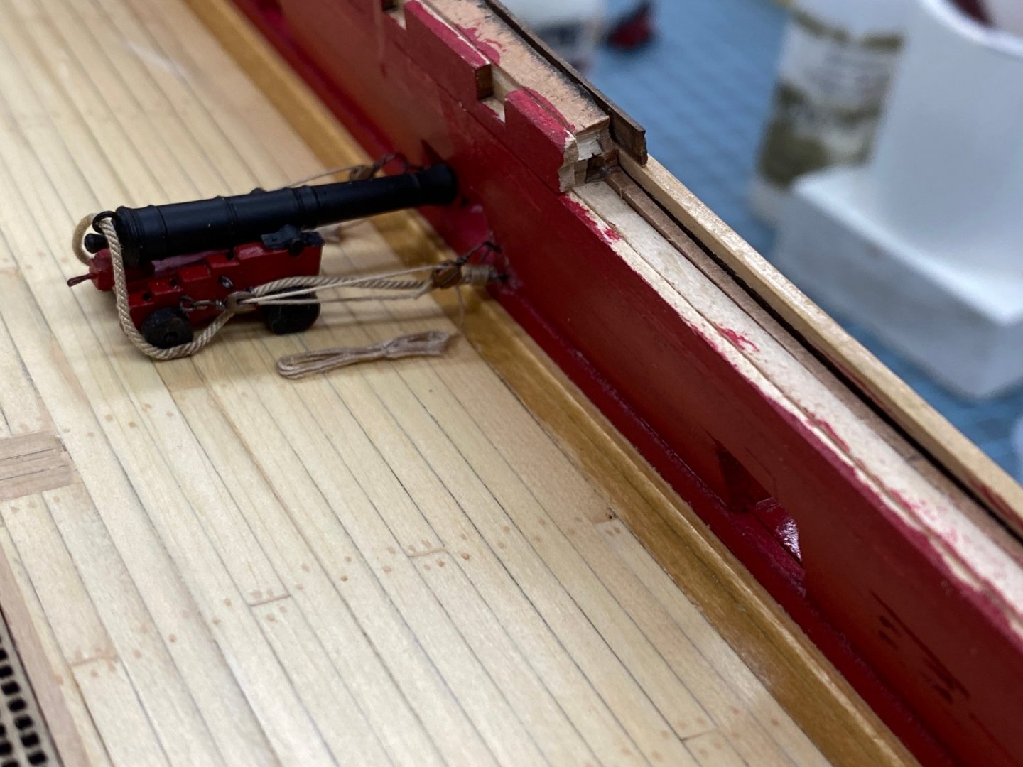
While looking at installing the Jeer bitts I found a minor issue with the plans. Sheet 4 (below) shows the bitts with the cleats on the sides. While sheet one appears to show the cleats on the fore and aft sides of the bitts. The instructions clearly show them on the port and starboard sides so that is where I put them. Also, although not marked in any way on the carrier sheet, there appear to be three each of the Jeer and Main bitts provided with the kit. The topsail sheet bitts are a mm or so shorter than the Jeer bitts although it would be easy to mix them up - don't ask me how I know. So here are the Jeer bits in place under the 11th Quarterdeck beam.

- 370 replies
-
- 4
-
-
- Model Shipways
- Confederacy
- (and 1 more)
-
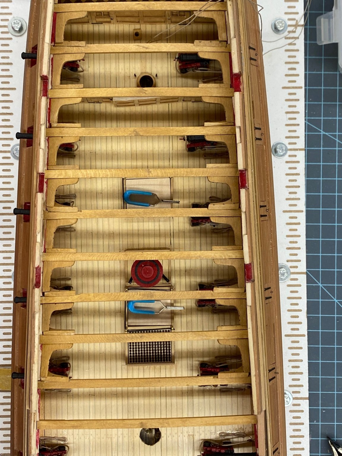
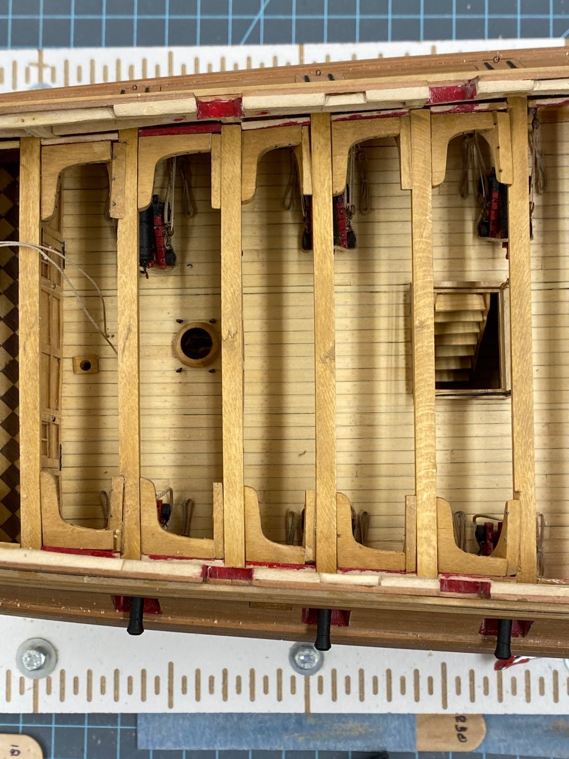
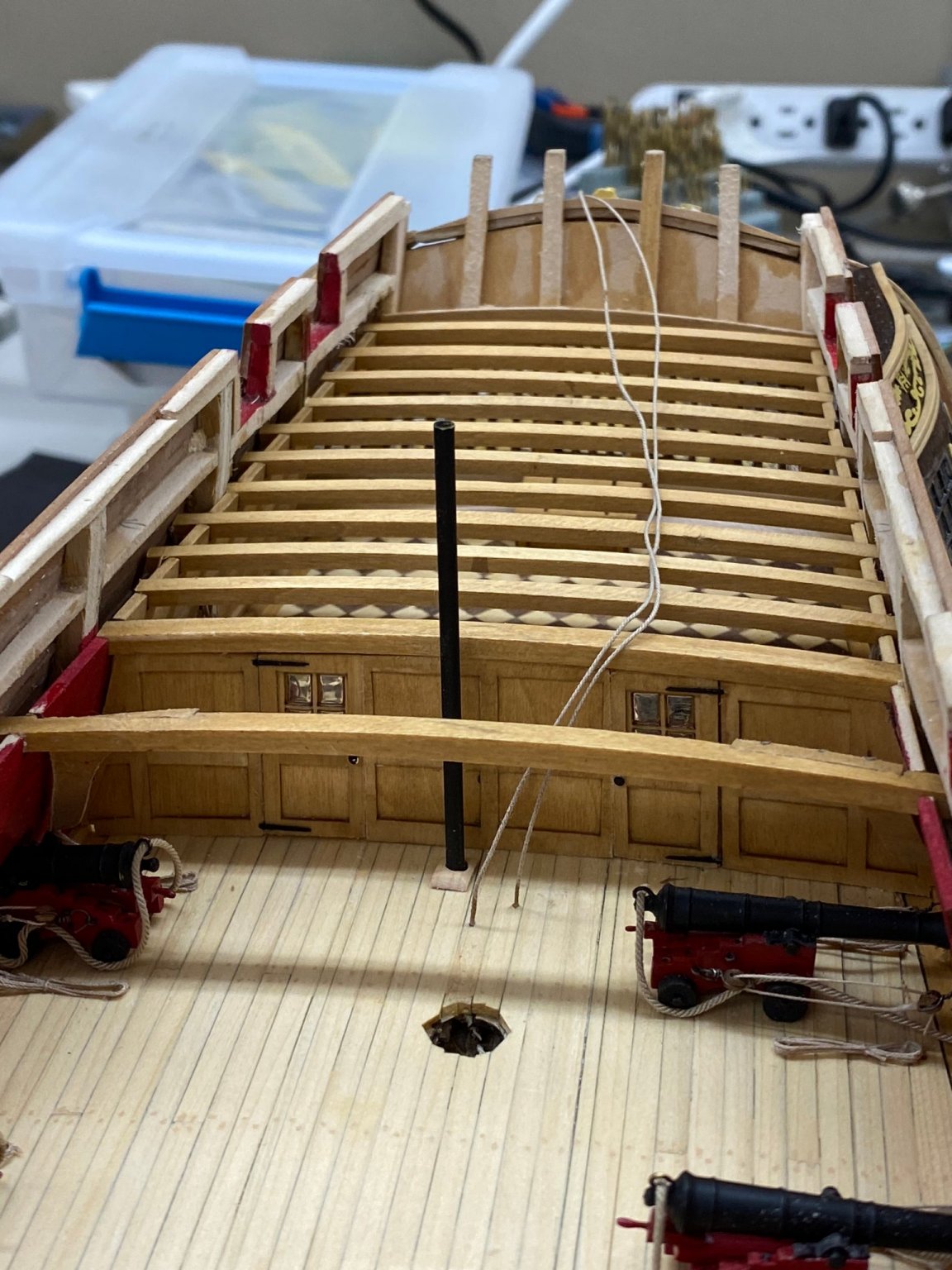
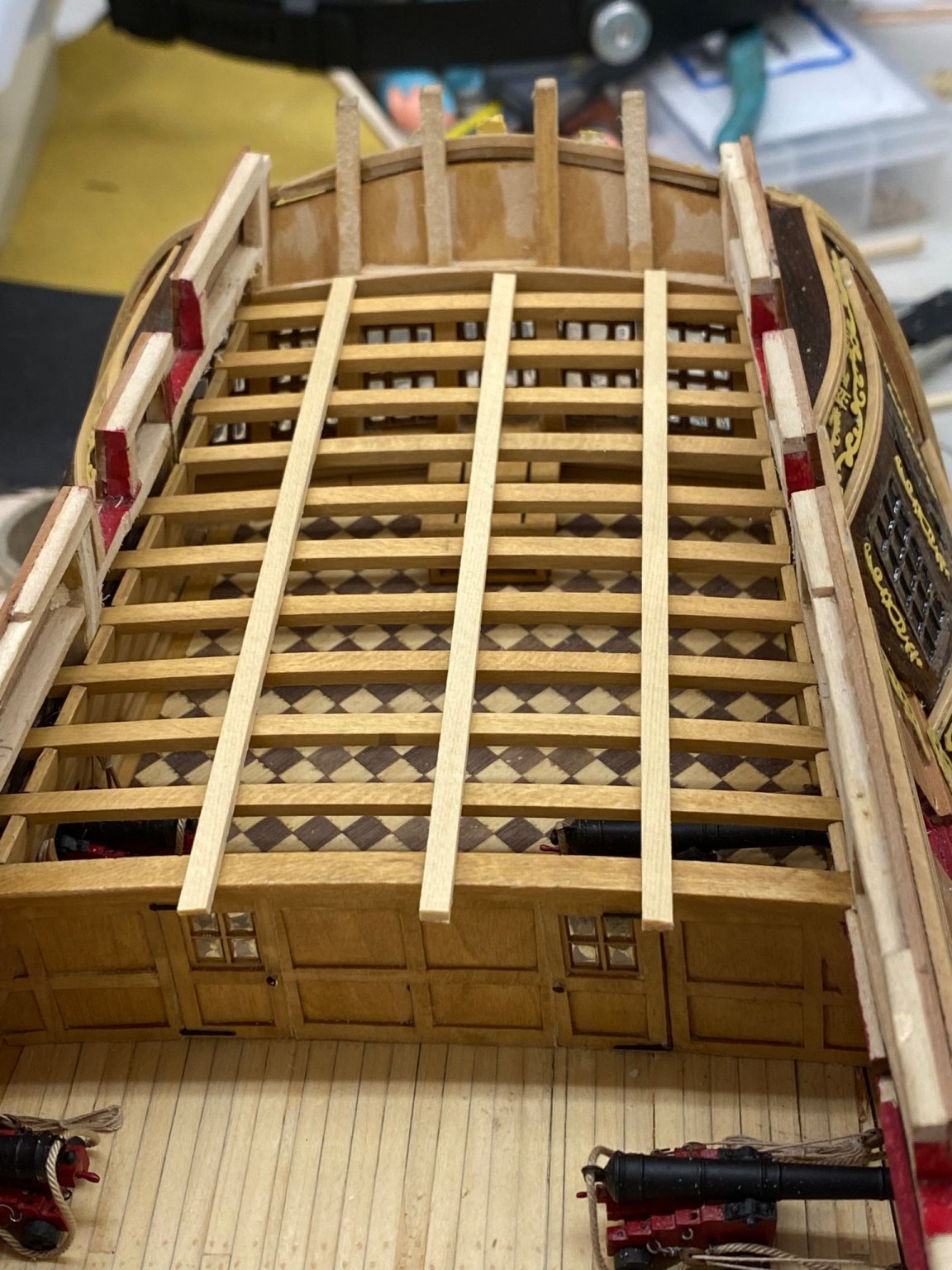
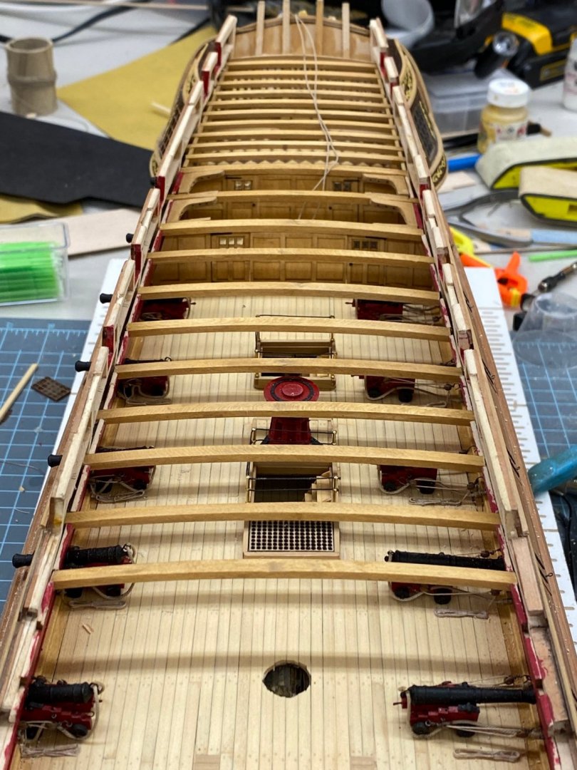
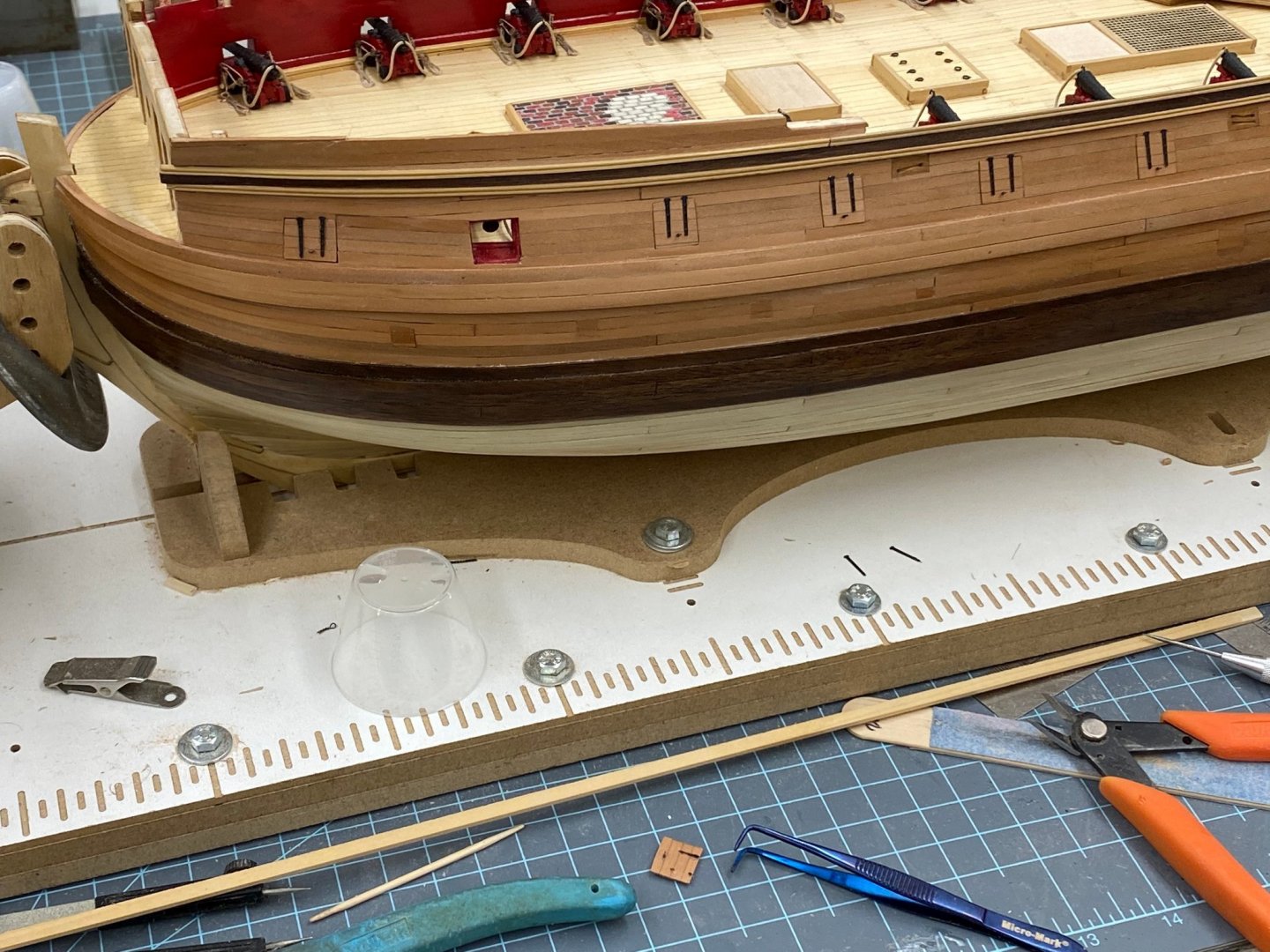
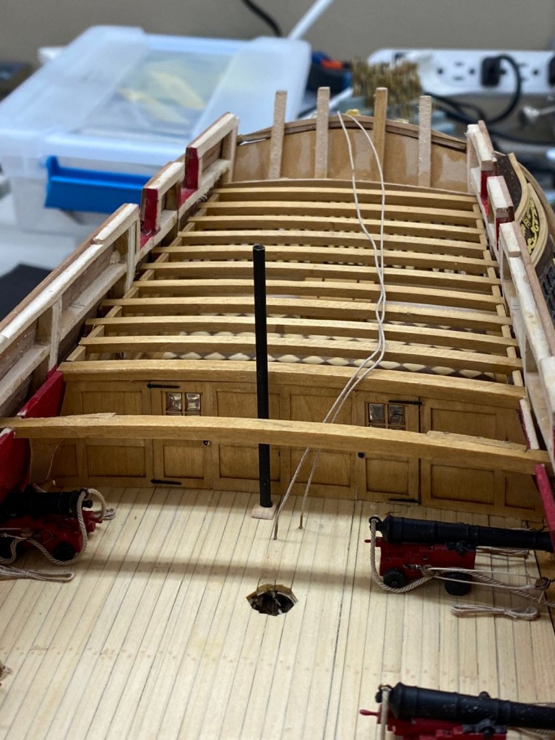
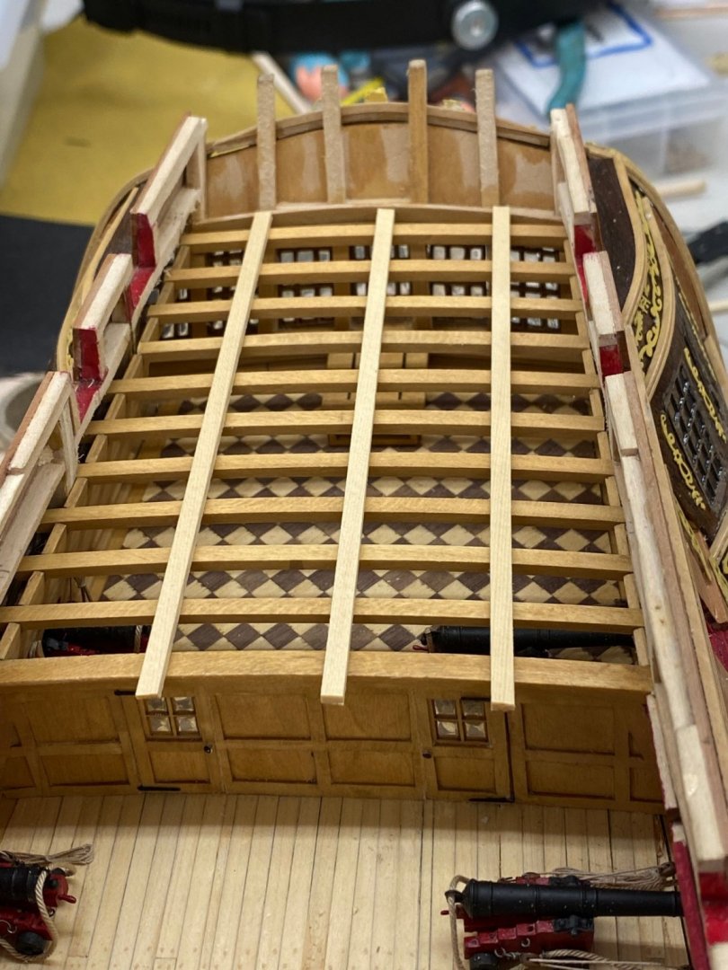
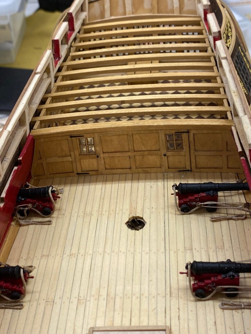
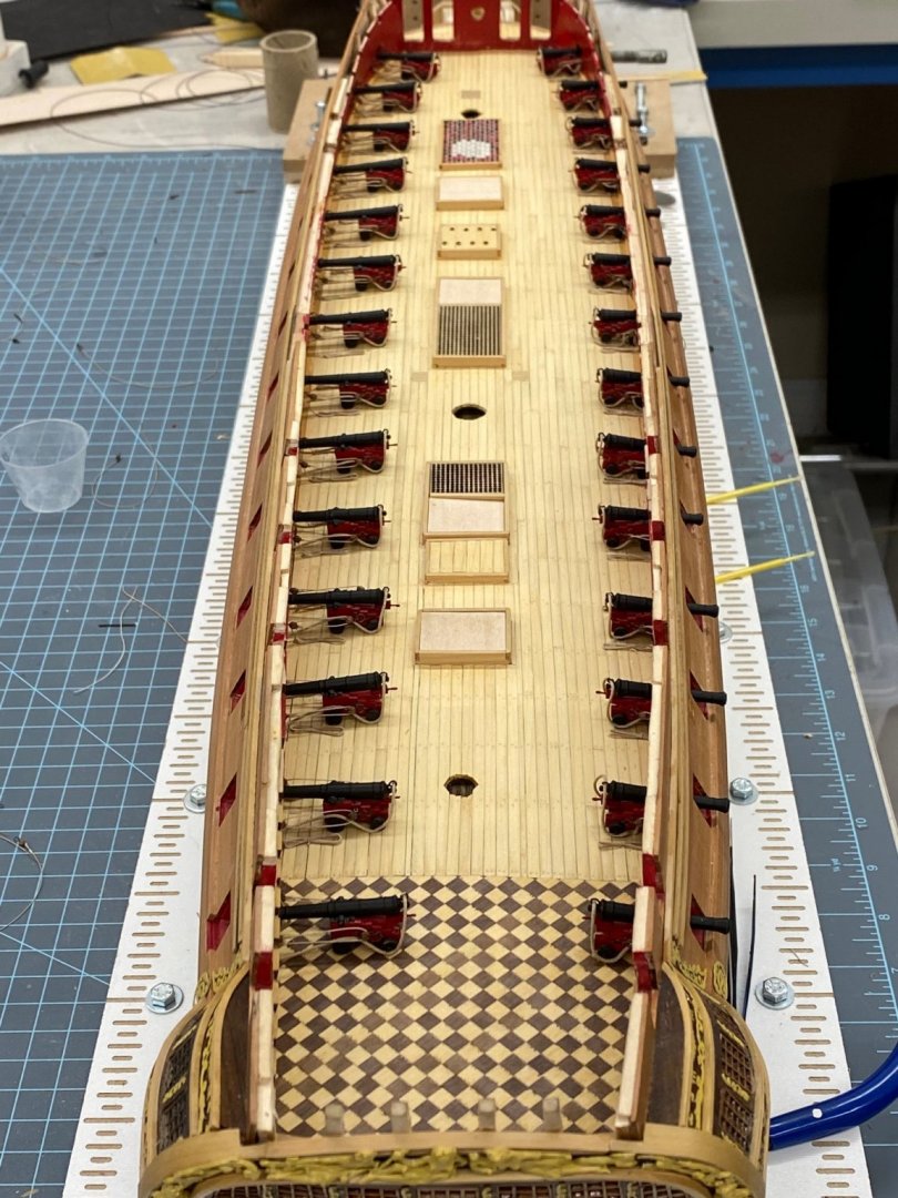
Seven of the eight deck beams that go in front of the second bulkhead are installed. The Jeer bitts go under the next one and all I need are the small cleats on the sides and they will be ready. Not going to miss the knees much. My model is a little "off" the drawings since it seems my deck beams are pretty much dead center on the gun ports while the drawings show the beams are mostly in the aft half of the gun port. Makes my hanging (I think) knees slope more to clear the gun port which makes them harder to hold in position while shaping the knee to fit the bulwark. More fun up forward, three of the six beams are over the gun ports so more lopsided hanging knees coming up. Here is the "view from above" with as things stand now. The blue clamps are there to hold the covers on the companionways. When I blow the sawdust (and other debris) out they fly up kind of defeating the purpose.

- 370 replies
-
- 1
-
-
- Model Shipways
- Confederacy
- (and 1 more)
-
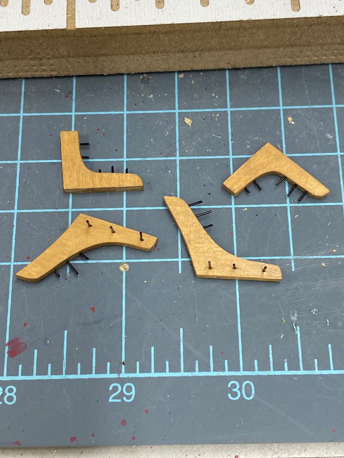
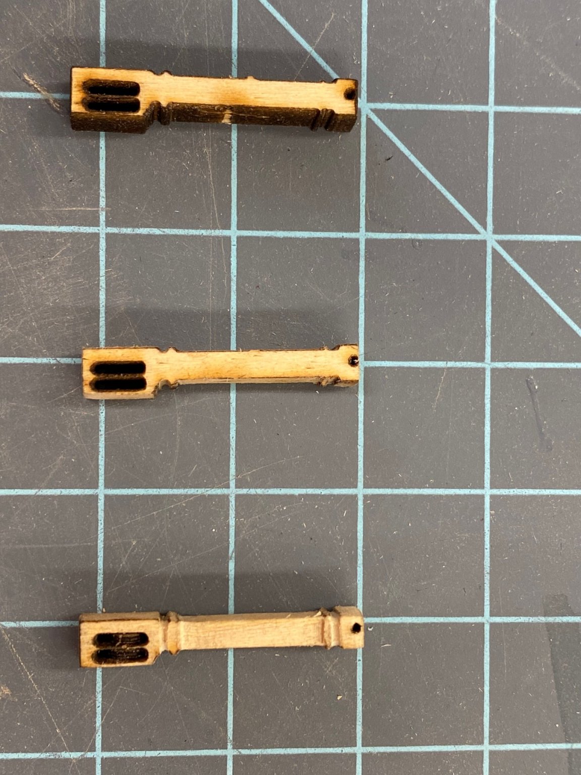
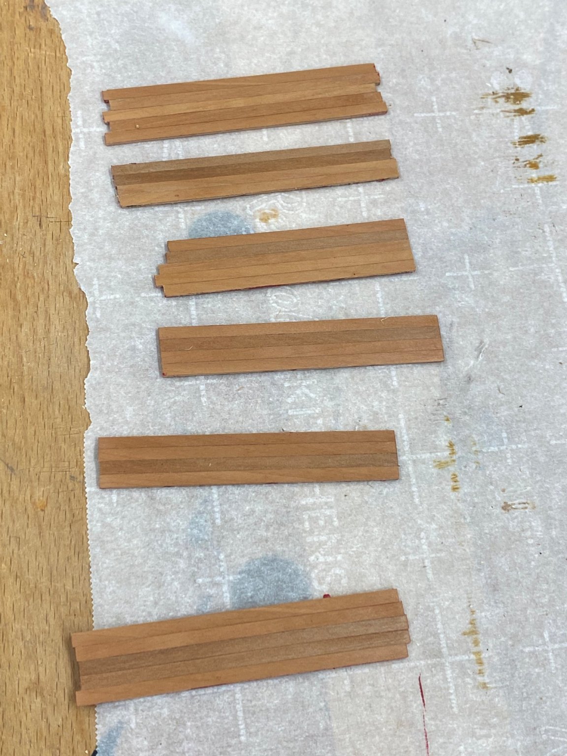
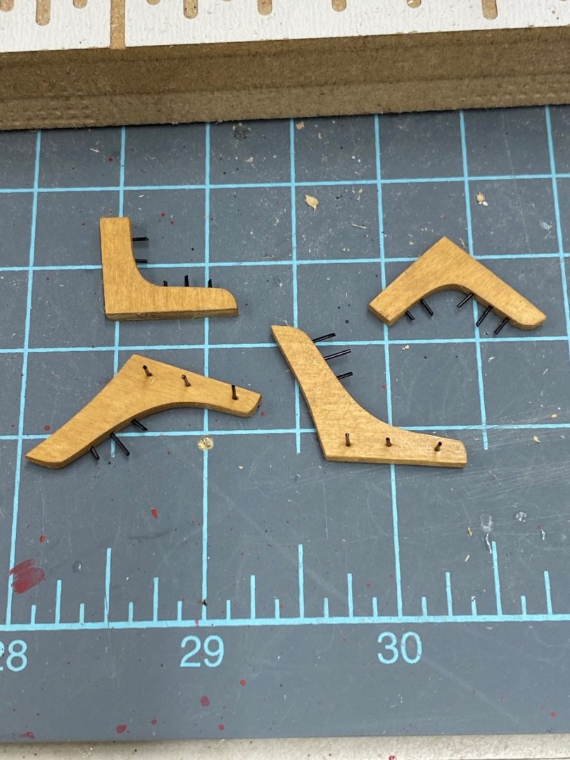
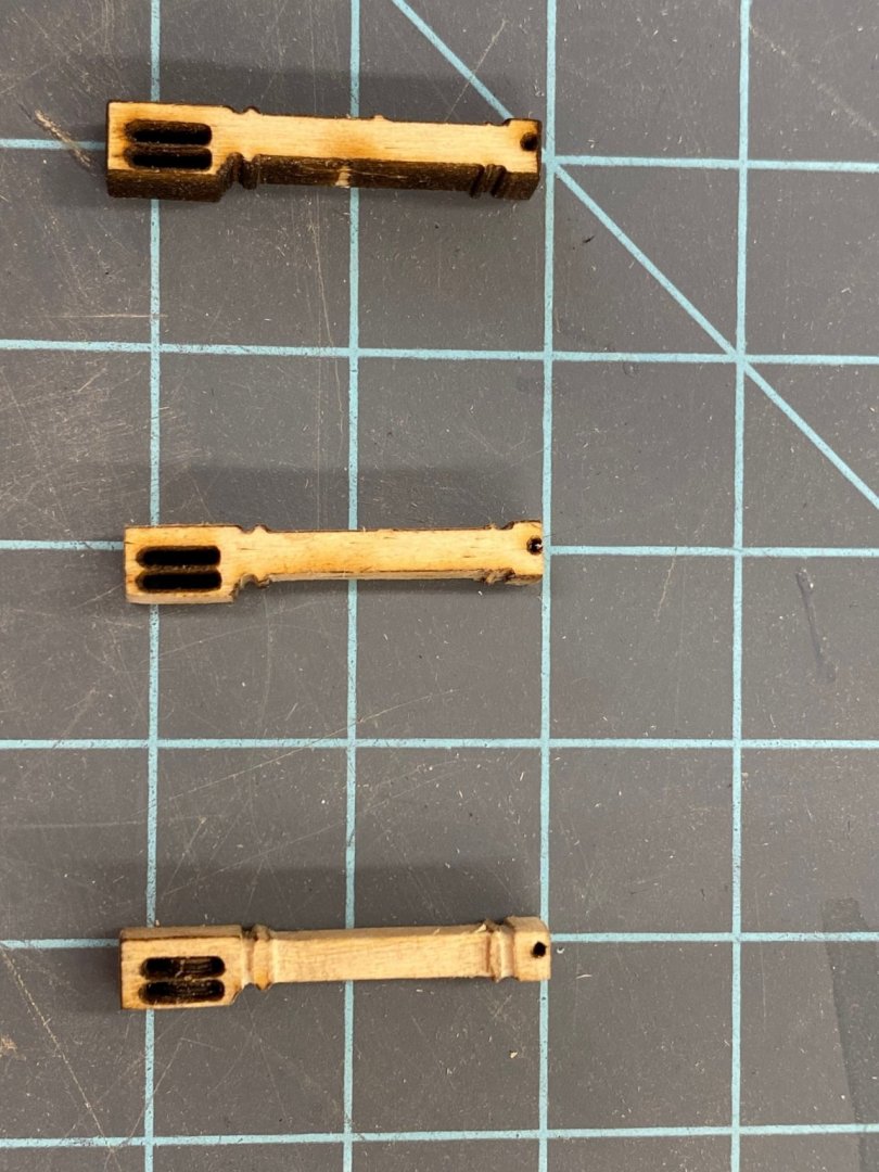
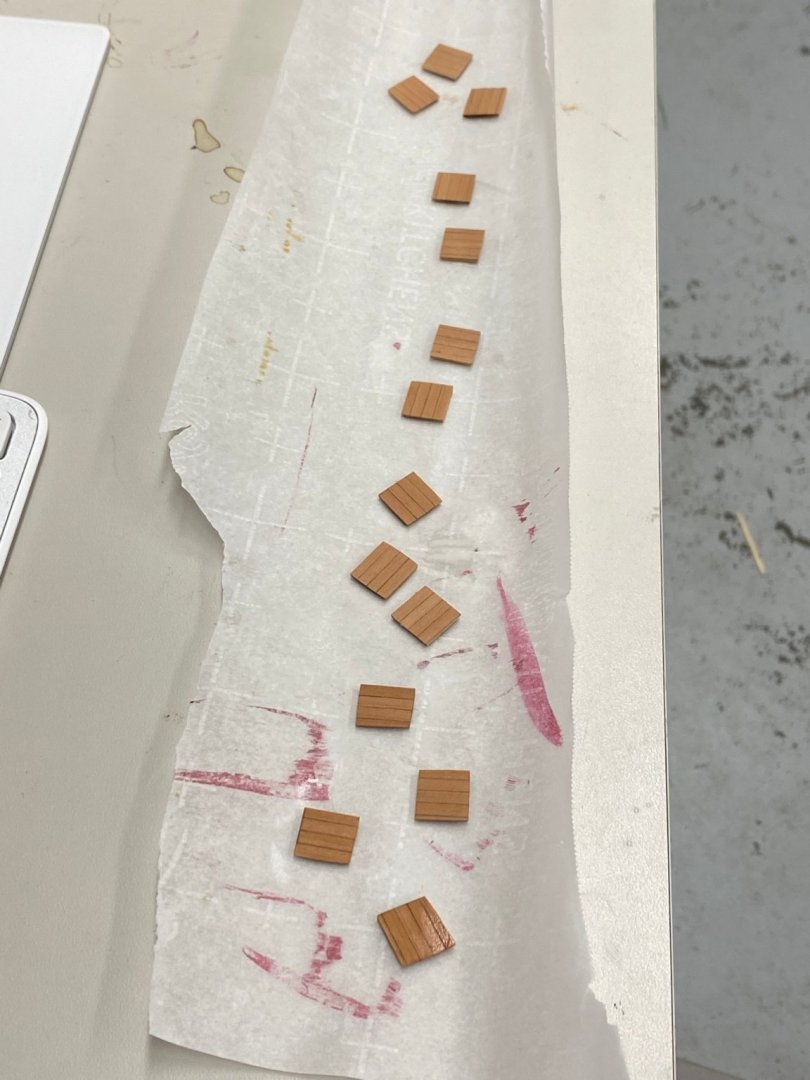
I decided to split my time between installing the quarterdeck beams and building the pumps and main/jeer bitts. Here is a set of knees waiting for trimming the "bolts" (aka monofilament fishing line - no need to dab black paint on the ends) and installation. And here are three (of the four) bitts being prepared for painting. The top one is as it comes off the carrier board The middle one is after most of the laser char has been removed and the bottom one is "finished" with molding continued around the non-lase cut sides. Wood is pretty "fragile" and keeping the corners "sharp" is a challenge (not always surmounted) . Bottom ones will get a final sanding (320 grit) before painting. Once these are finished it is back to the deck beams then on to the pumps.
- 370 replies
-
- 2
-
-
- Model Shipways
- Confederacy
- (and 1 more)
-
Slow going with the knees. 24 holes to mark and drill and "populate" for each beam. I think I finally got a system for the beams where the lodging knee has to be angled to clear the gun port (seems like every other one on my model). I cut an angle into the end of the beam to get the proper "set" of the knee and glue one end up before gluing in the beam. It is really hard (for me) to get the knee in place, aligned with the bulwark, and at least the same distance above the beam at both ends and still have another hand to lay some thin CA into the seams. If I can get one done "off-board" that cuts the frustration in half. So here are the first three of the eight beams forward of the second bulkhead, or the first six of the big beams under the quarterdeck.


- 370 replies
-
- 3
-
-
- Model Shipways
- Confederacy
- (and 1 more)
-
Next step (per the instructions) is to add eight more deck beams and the associated knees to the hull. So I cut and fit them and hopefully got them in without distorting anything. Not glued in yet. Will do that as I get the knees in place. Three knees need to be angled (slightly compared to the one between the bulkheads) to clear the gun ports. Now for the real fun - "the knees".
- 370 replies
-
- 4
-
-
- Model Shipways
- Confederacy
- (and 1 more)
-
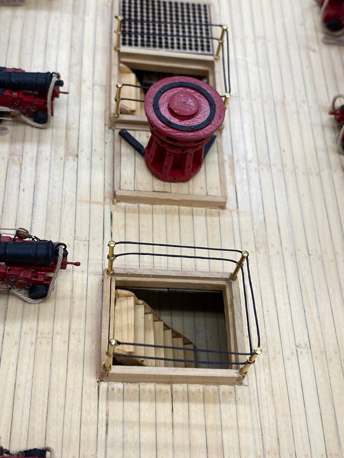
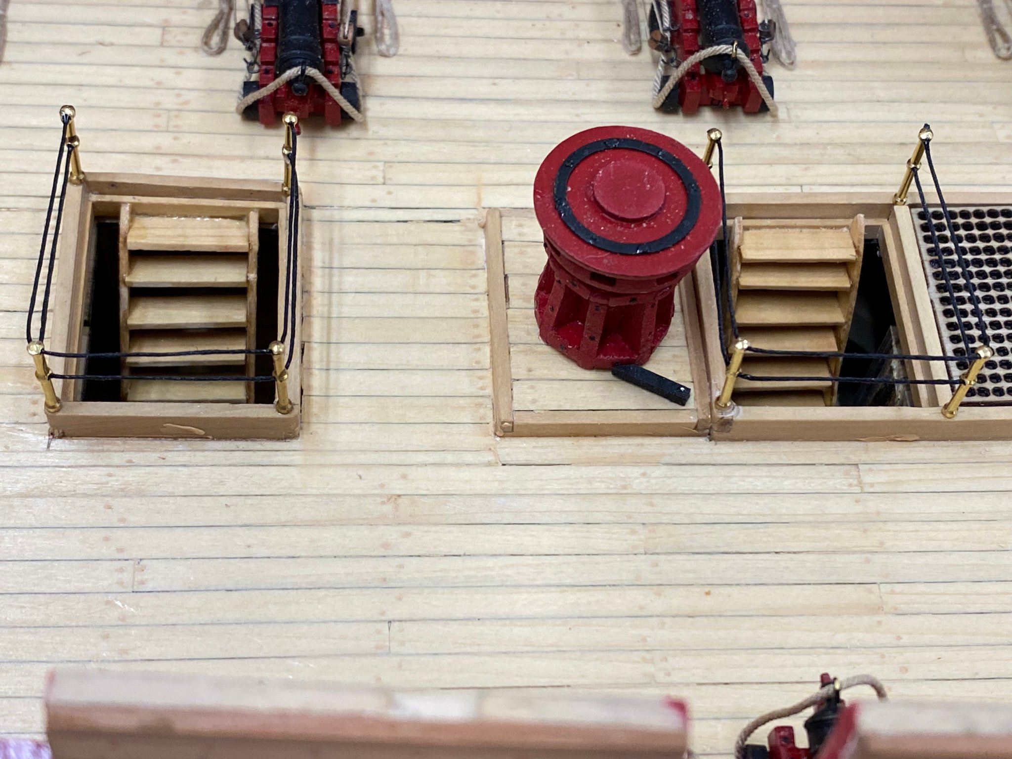
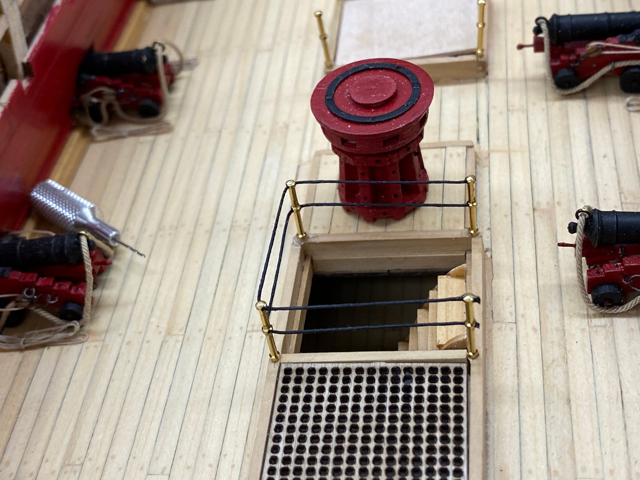
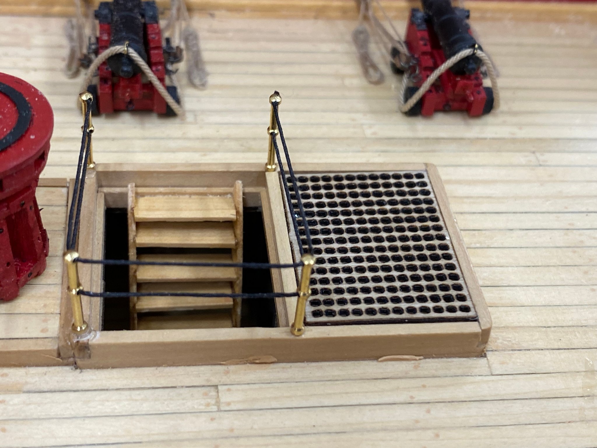
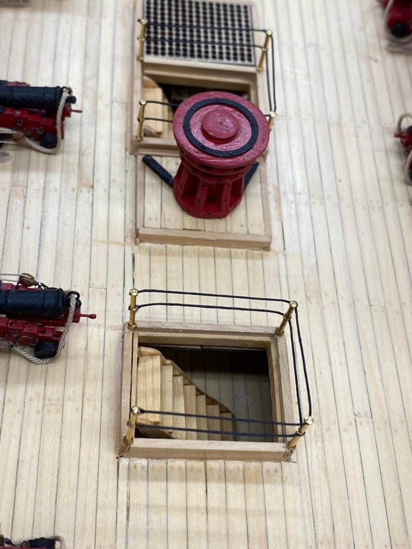
Completed the safety lines on the two aft companionways and added the two capstan pawls on the platform.

- 370 replies
-
- 2
-
-
- Model Shipways
- Confederacy
- (and 1 more)
-
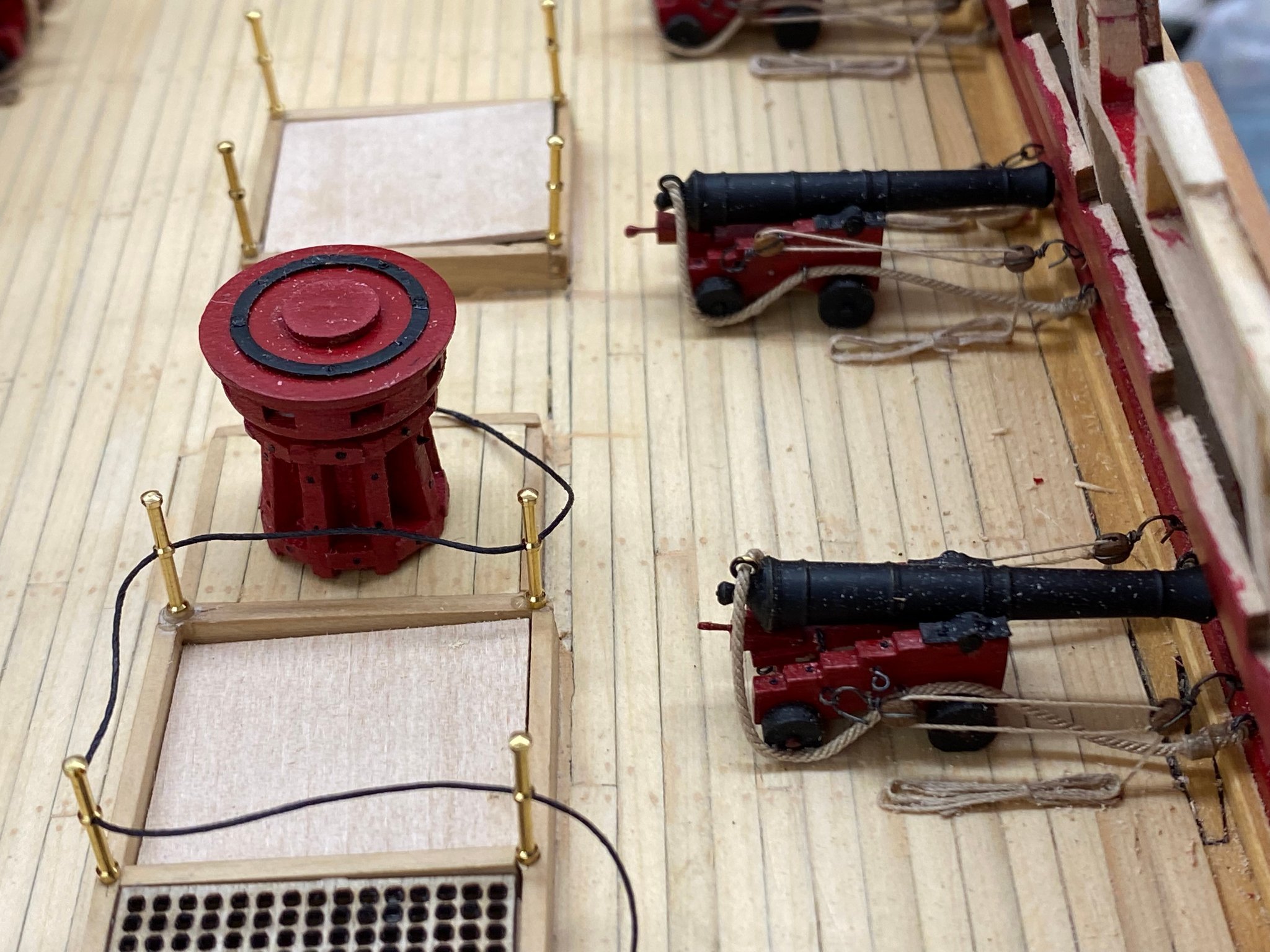
So I glued in the capstan that I assembled while waiting for the cannon carriages to arrive and then looked at the stanchions on the photo etched sheet. Not really very sophisticated a flat short "stick" with a flat circle on the top. I wonder just how easy will it be to bend one of these out of shape after they are installed. So I looked through my parts locker and found enough brass stanchions that are very close to the same length as the ones on the sheet. I believe they came from BlueJackets sometime ago and luckily I have enough for all the stanchions around the companionways. The bad news is these stanchions are set up for two rows of "railings" rather than the single row in the kit supplied material. The instructions also would make the railings out of 28 ga wire rather than line. For these stanchions I think line is going to work better (holes in the end are much smaller than on the kit supplied items). And since these stanchions have two sets of holes I will rig two rows of safety lines around these companionways. Here is a shot with the capstan and both sets of stanchions in place and the line for the first set of safety lines in place ready for tightening. I have not decided yet whether to try and make the lines straight (no sag) or have a slight sag to them. I really do not want to have strain on the stanchions as they are not that strong and I might bend one (or more) in the straightening process. After playing around with the safety line I figured out that getting a more or less similar "sag" in all six lines was a "bridge too far" and decided to get the lines as "straight" a reasonably possible. Here is the aft companionway with the cover removed and the safety lines in place.


- 370 replies
-
- 2
-
-
- Model Shipways
- Confederacy
- (and 1 more)
-
Here is the second bulkhead in place - not yet glued in place but that is next. Capstan (already built, and stanchions around the hatches next. I have not decided yet whether to use the stanchions included in the photo etched sheet or find something else.
- 370 replies
-
- 3
-
-
- Model Shipways
- Confederacy
- (and 1 more)
-
Finally all the gun port doors are finished. Now on to the sweep port door hinges. And here they are: With the exterior now as complete as it will be for awhile I can shift full attention back to the deck beams and other interior details.

- 370 replies
-
- 3
-
-
- Model Shipways
- Confederacy
- (and 1 more)
-
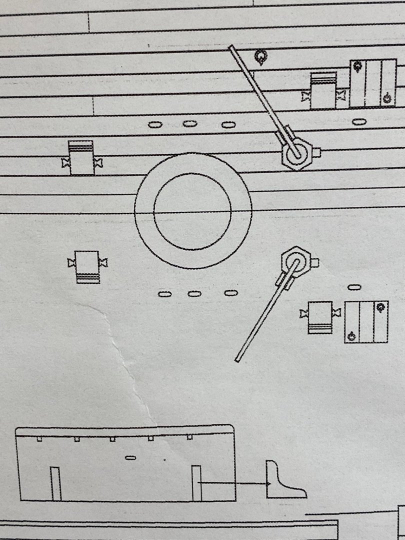
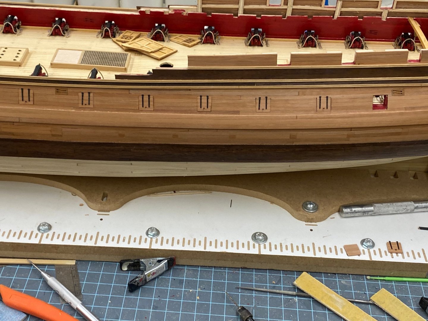
I thought I got the gun port doors ready for installation but when it came time to actually glue them in place I was 12 for 14 (still enough to be MVP in either league). The second door just didn't fit as well as I remembered and number 12 the planks were way out of line. Not sure what I was drinking the when I did that one but I hope I have some left. Here are the 12 doors that I did install - building new ones for #2 and 12 - then paint, W-o-P and eyebolt - then maybe I can move back to the deck beams and knees after I put the hinges on the sweep and ballast ports of course. I did install the first beam/hanging knee combo forward of the aft bulkhead as well as the speaking tube and lines for the wheel. I have to fab the other speaking tube base and install the mast coat and the four eyebolts around it. Speaking of the speaking tube base, the picture in the instructions shows it round, but the drawings shows it rectangular. I went with the drawing since making really round disks is not my specialty. Here is how it looks so far.

- 370 replies
-
- 2
-
-
- Model Shipways
- Confederacy
- (and 1 more)
-
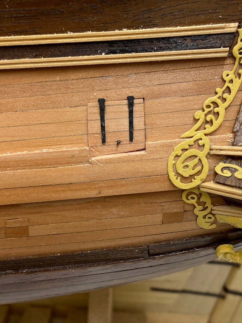
I put another coat of W-o-P on the gun port doors, added the hinges and am in the process of adding the eyebolts. Rather than use the eyebolts that I have left over from the gun carriage tackle I made some new, smaller ones (34 gauge wire with .025 diameter eye) for the gun port doors. I find it difficult to believe that the same size eyebolts would be used in both places since all the gun port door eyebolt has to hold up in the gun port door, not haul around a 12 pounder gun and gun carriage. Anyway, I got one done (after-most gun port) and could not resist seeing how it looks installed. Pay no attention to the saw dust on the wales or the dents in the door and the gap at the bottom. I may try and sand down the forward part of the lower end of the door to make it more even but will wait and see how the rest of the doors look. I also have to add the hinges to the sweep port doors and the hinges on the ballast port door.
- 370 replies
-
- 3
-
-
- Model Shipways
- Confederacy
- (and 1 more)
-
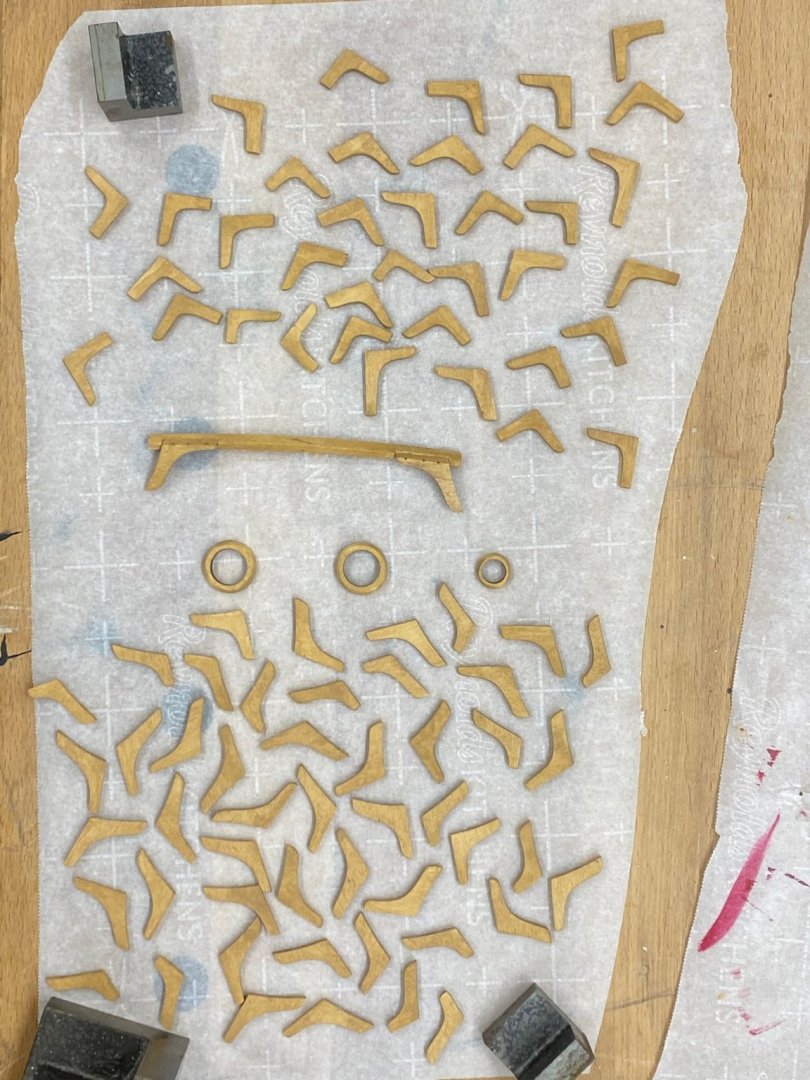
Working on the gun port door details (hinges and eyebolts) and put a coat of varnish on the knees. So here are the varnished (Minwax Polycrylic water based - I have never had much luck with W-o-P anywhere but on large surfaces) hanging and lodging knees, the three mast coats and the first "assembled" deck beam and hanging knees forward of the aft bulkhead. I measured and I should (ish) be able to get the assembled beam/knees into place but... Next up for these is to drill the holes and add the monofilament "bolts" so they are "ready to go" as I get to the next deck beam.
- 370 replies
-
- 3
-
-
- Model Shipways
- Confederacy
- (and 1 more)
-
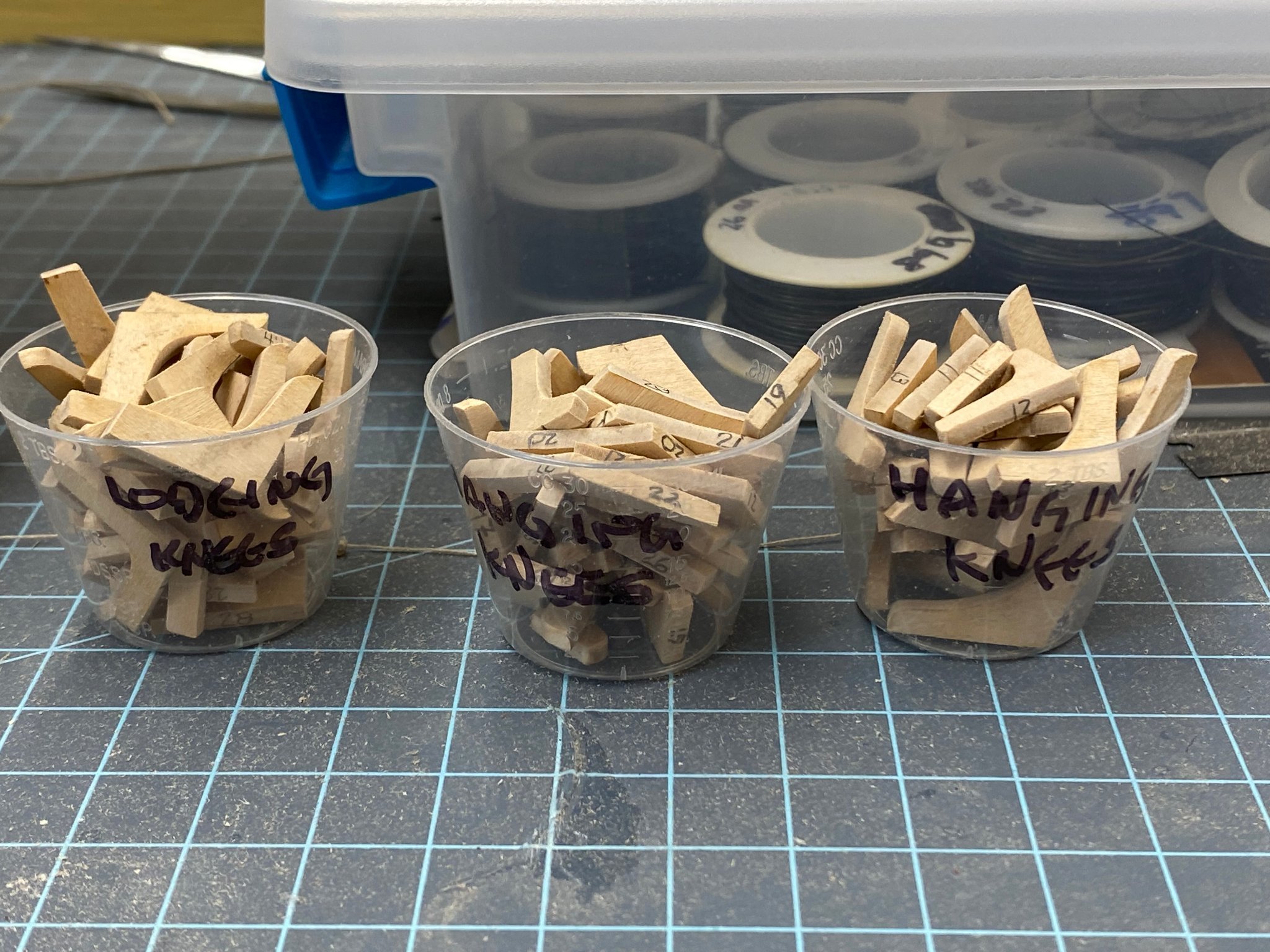
While messing around with the gun port doors I decided it was probably time to get all the knees off the carrier sheet, laser char removed, stained and maybe varnished before starting the deck beams in earnest. So here they all are ready for stain. I marked each one of at least one of the edges that I thought would not show. Turns out for the ones extending down (I forget which is which) the only edge not visible is the one against the outer bulkhead. I had to sand off and reapply the markings on all of those. I finished the port side gun port doors and here they are after a coat of W-o-P. I have to paint the inside red after this dries and then maybe another coat of W-o-P.

- 370 replies
-
- 4
-
-
- Model Shipways
- Confederacy
- (and 1 more)
-
Port side gun port doors are half done. Hopefully get these finished today so I can get them painted, varnished and have the eyebolts installed. Am wondering about the hinges. The instructions use the part of the hinge that would be on the hull (I assume) as a "pin" to be inserted into a hole drilled in the hull. For the closed doors I assume this part needs to go on the hull above the door. Or was the top of the hinge on the inside of the gun port? Maybe I need to look carefully at some pictures showing closed gun ports.

- 370 replies
-
- 3
-
-
- Model Shipways
- Confederacy
- (and 1 more)
-
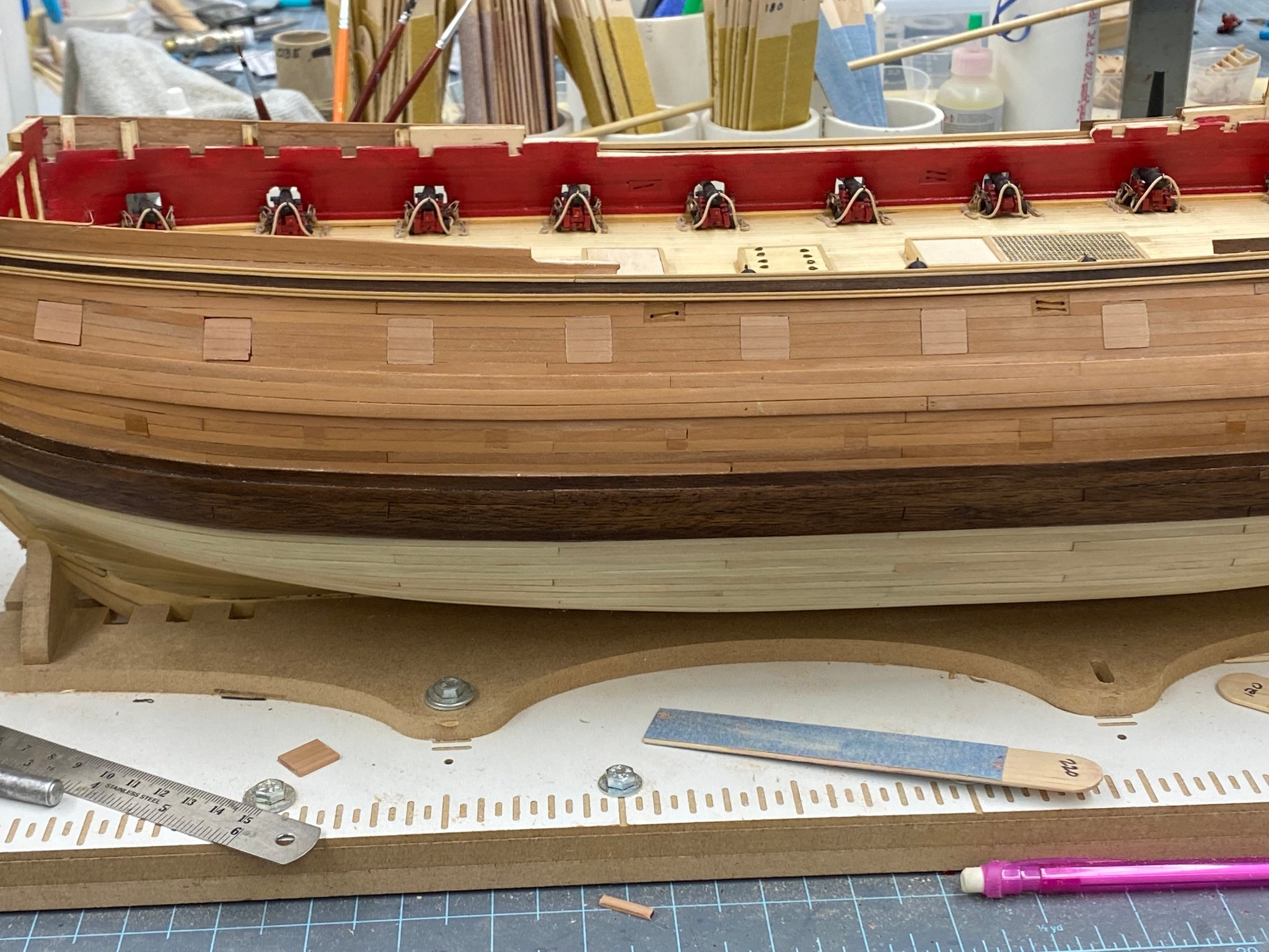
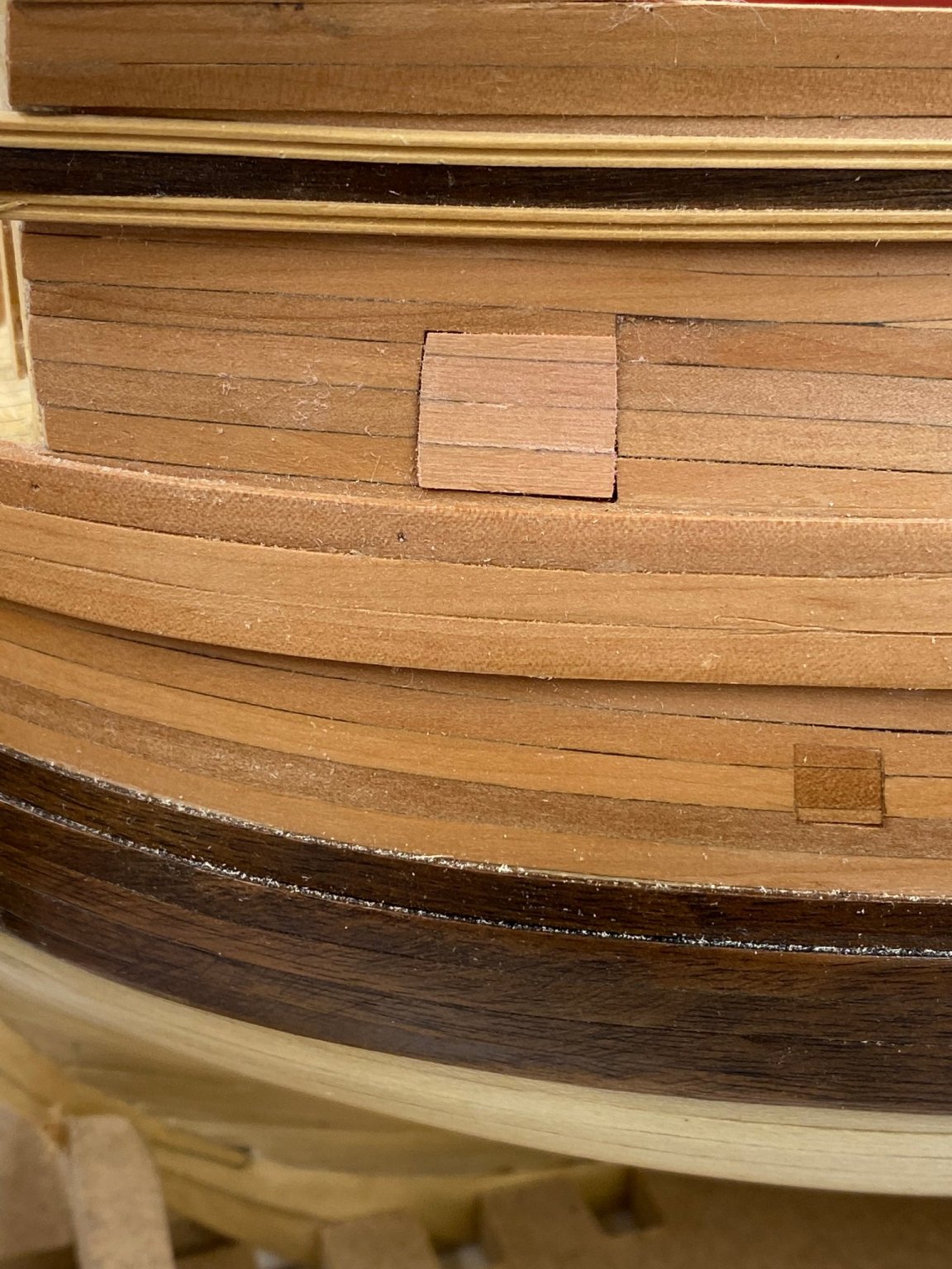
Here is the forward most gun port with the door in place - no Wipe-on-Poly or hinges or eyebolt yet but it does fit pretty well. Only 13 more to go, on this side.
- 370 replies
-
- 4
-
-
- Model Shipways
- Confederacy
- (and 1 more)
-
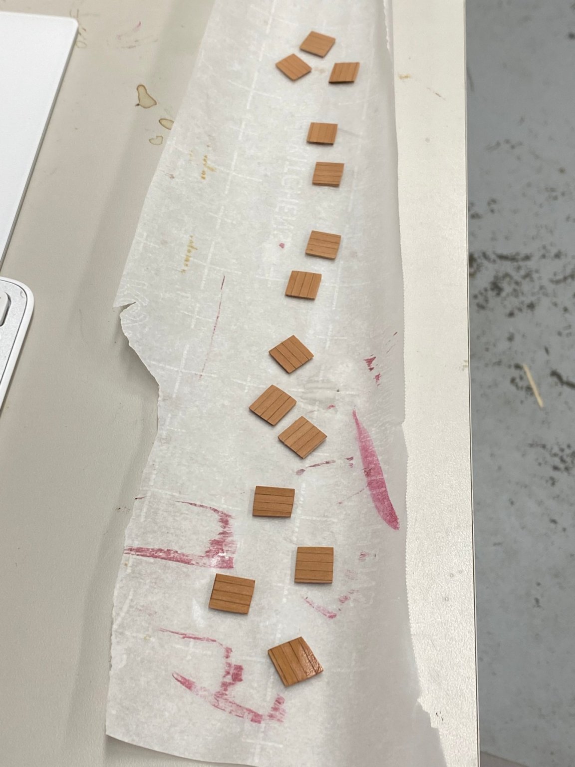
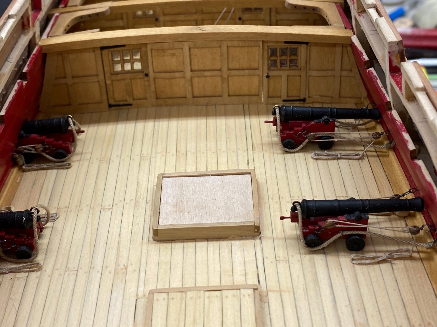
I made a "false start" on the gun port covers. I forgot to add the caulking between the planks (aka graphite from a pencil lead) plus I had to take a bit off each side of the planks to get the white glue residue off. Decided on a "do over" so I got a 24" piece of Swiss Pear and thickness sanded it to 1/8" then cut five pieces 3/32" thick. I used the pencil and white glue to glue them together and when it is dry later today will use the thickness sander to get it back down to 1/16" thick and (hopefully) have a nice smooth surface (with caulk) ready to make the gun port doors (lids?). I estimate that this one specimen could make all 28 gun port lids but I'll settle for 14 now. While waiting for the glue to dry I fitted the center section of the aft interior bulkhead and the floor beams for the aft part of the quarterdeck. Unfortunately the center of the bulkhead does not line up with the center of the deck, off about one plank width. But it will be really hard to tell with the next bulkhead only 2" forward. A lesson learned, secure the center of the bulkhead first and work out from there. Mistakes will be much less noticable between the doors and the outer bulkhead sections. I cut some scrap basswood to check the "lay" of the beams before gluing them in place. Looks "okay" to me.
- 370 replies
-
- 4
-
-
- Model Shipways
- Confederacy
- (and 1 more)
-
Working the port side gun port lids and the internal bulkheads in parallel. Building up four and five row pieces of side planking to use for the gun port lids. Have not figured out exactly how to fit them but I recognize that they will have to be "taller" then the port so I can get the planks to "line-up". I had previously build up the bulkhead pieces and thinned them down per the instructions. Also per the instructions, the bulkhead pieces are some what larger than required I shortened and took material off the edge pieces to match up with the interior bulwarks (ish). I added the hinges and door knobs to the doors and glued the door and edge pieces in on both sides. Once this is dry (tomorrow) I will "adjust" the center piece so it fits between the two doors. Hopefully it will fit with the center of the piece on the centerline of the deck. Here is a picture of the bulkhead with the edge pieces and doors in place.


- 370 replies
-
- 3
-
-
- Model Shipways
- Confederacy
- (and 1 more)
-
Wooo-Who - guns are complete. Thinking about building the port side gunport doors now and installing them so I don't have to contend with them while adding the external details (channels etc.). Otherwise it is time to start the internal bulkheads at the stern.
- 370 replies
-
- 6
-
-
- Model Shipways
- Confederacy
- (and 1 more)
-
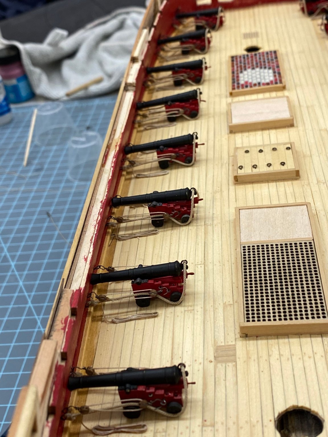
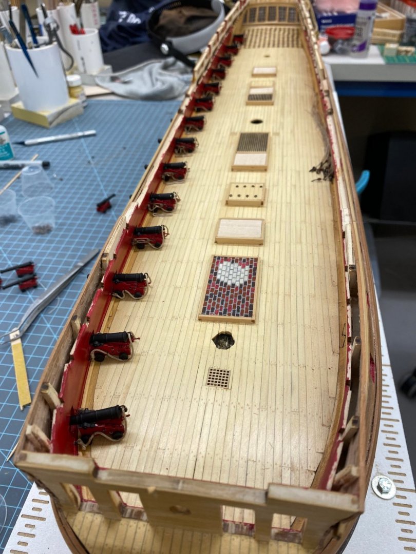
Eight of the 14 port side cannon installed and rigged. I am getting this down to a "routine" just in time to be completed. Here they are:

- 370 replies
-
- 5
-
-
- Model Shipways
- Confederacy
- (and 1 more)
-
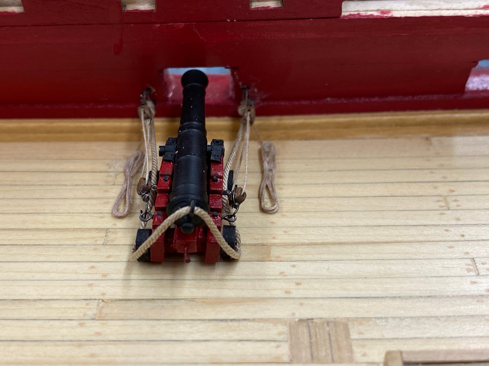
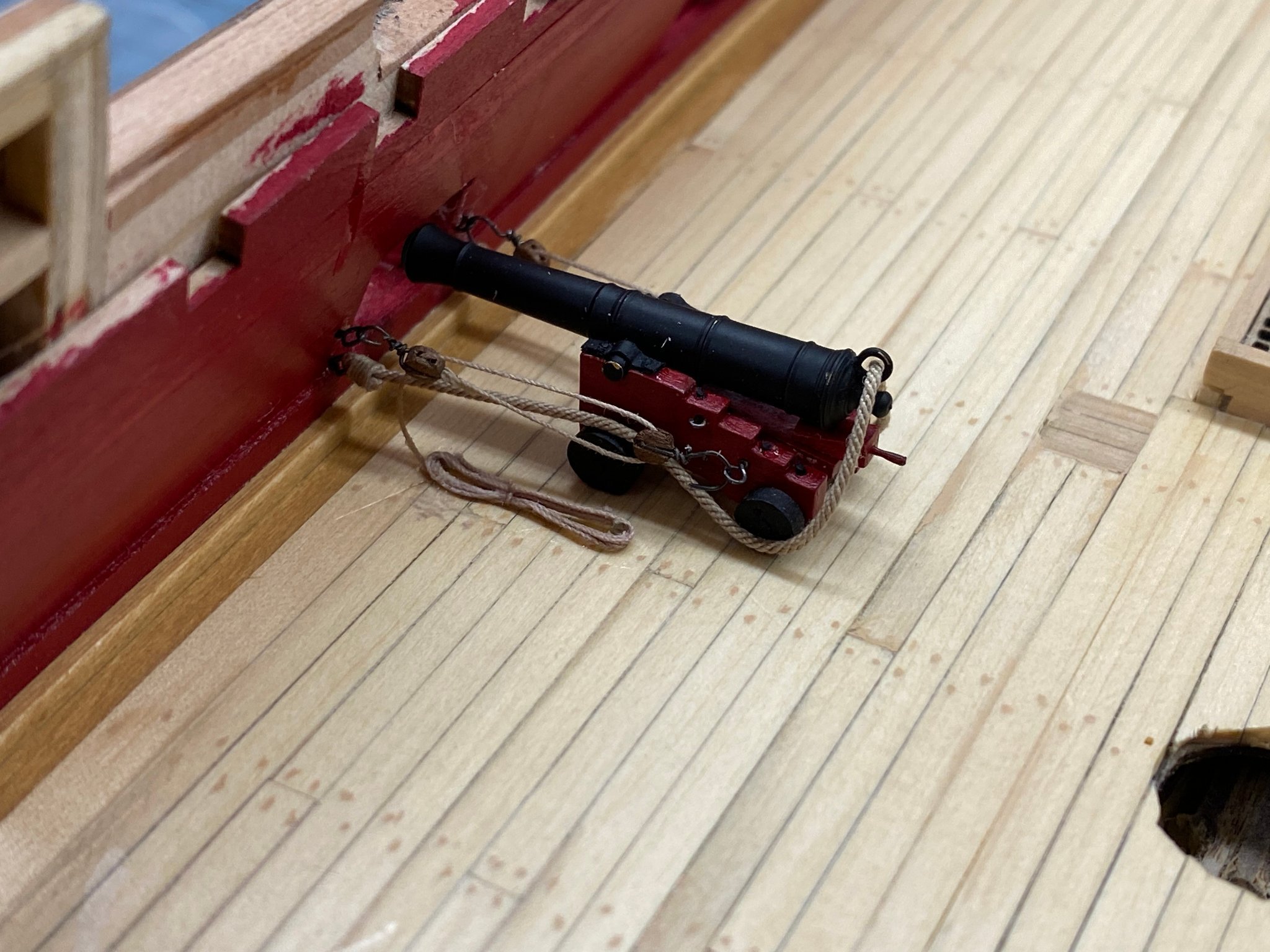
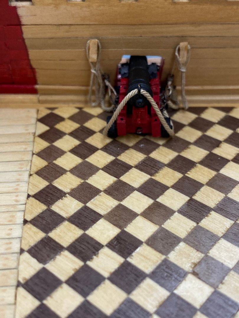
So here is my "test" cannon in the "stowage" position. I did glue this one down while I adjusted the breeching tackle so I guess I am committed to do the rest this way now.


- 370 replies
-
- 2
-
-
- Model Shipways
- Confederacy
- (and 1 more)
-
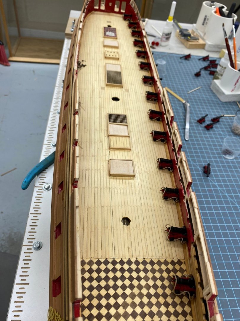
Starboard side cannon are all installed and the out-haul tackles are complete. Here is a shot of the four after most (except for the one in the Great Cabin which can be seen in the post above. I arranged the other guns approximately where they would be if I opt to place them where (IMHO) they would be stowed when underway. Jury is still out on this. The upside is I may not have to redo all 28 out-haul tackle since there will be significantly more room with the carriages back another 20mm or so. I guess I will rig one to see how easy/hard it will be to rig them back. Probably will have to glue them down before rigging to try and keep the breeching tackle the correct length. I'll try one without gluing the carriage down to see how it goes.
- 370 replies
-
- 2
-
-
- Model Shipways
- Confederacy
- (and 1 more)
-
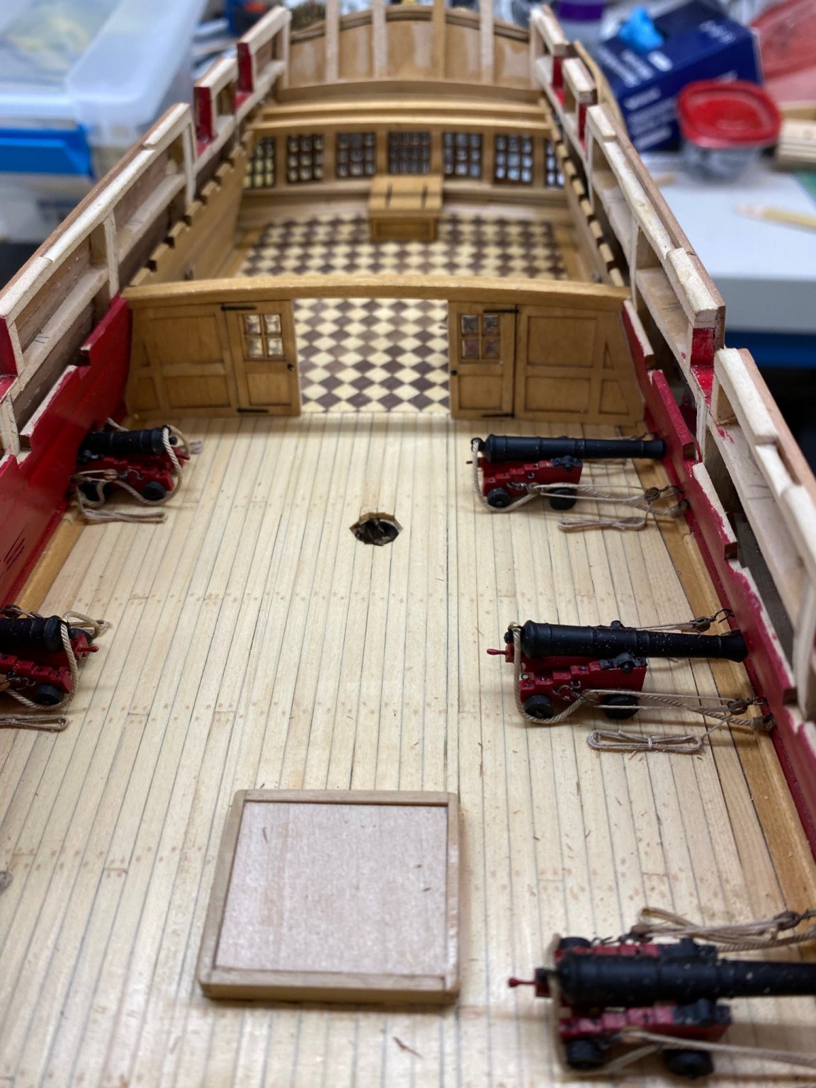
While installing the out-haul tackles on the starboard side guns I was thinking about the storage for these lines. Given the usually wet nature of the deck I thought that probably these lines may not even have been routinely kept on the guns but rather stored somewhere nearby and rigged as part of "beating to quarters". When I got to the Great Cabin I thought that at least the Captain would not want the lines laying on the deck (no matter how smartly coiled) since space is always at a premium the floor space could be used for something else (chair, locker, etc.) so I put two cleats on the bulwark and hung the lines for the out-haul tackle on them. Here is what it looks like. All the starboard side out-hauls are complete except for putting the rope coils in place.
- 370 replies
-
- 2
-
-
- Model Shipways
- Confederacy
- (and 1 more)
-
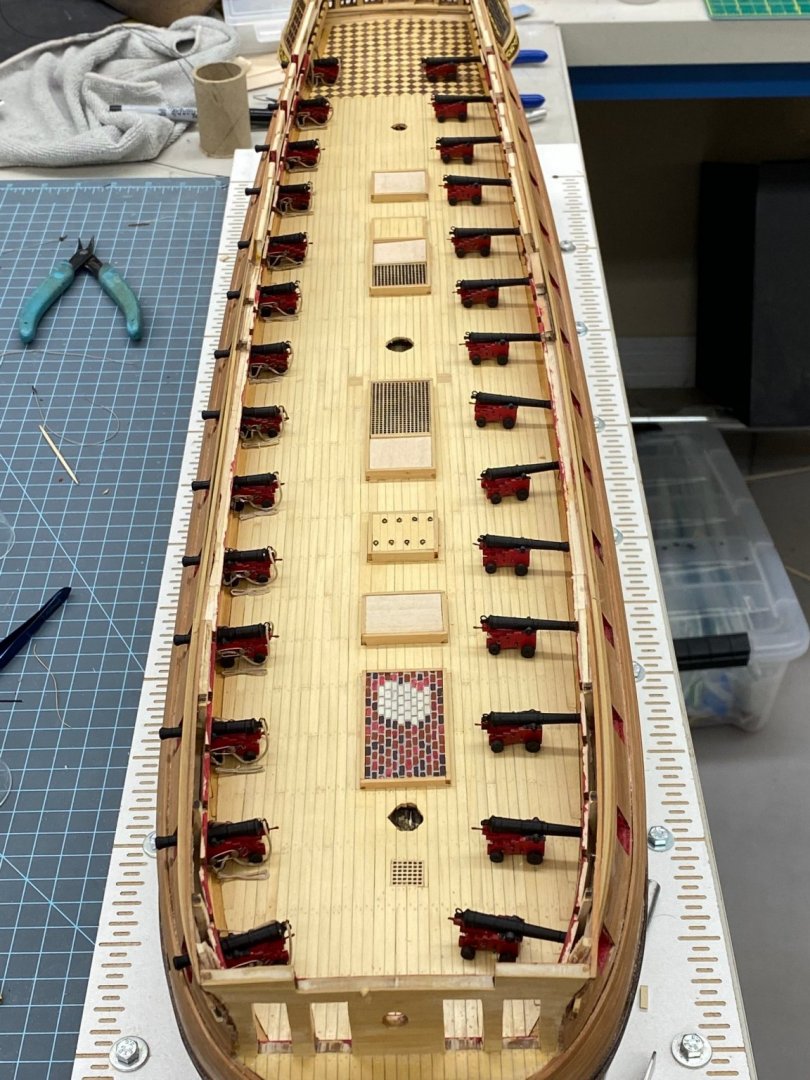
All 14 of the starboard side guns are in place with at least the breeching tackle secured to the bulwark. Next is the out-haul tackle for the nine that I did not do before I changed tactics. With the starboard side positioned at the gun ports I need to decide if I am going to position the port side guns in a similar manner or have them further back so that I can have to port side gun ports closed. Not that I am anxious to have to make 14 gun port covers that match the planking pattern on the hull but it would make the two sides "different". First order of business is to make sure there is nothing that gets installed later that would be impacted by the gun carriages being about 20mm further inboard. You would hope not since the guns clearly had to move back that far in recoil and allow the gun crew to reload without having to reach through the gun port to get the shot and powder in the barrel - not to mention trying to swab out the barrel. So here is the starboard side with all the guns in position waiting for me to add the out-haul tackle.
- 370 replies
-
- 2
-
-
- Model Shipways
- Confederacy
- (and 1 more)
-
Thanks Schooner - necessity is the mother of invention - or so I have been told.