HOLIDAY DONATION DRIVE - SUPPORT MSW - DO YOUR PART TO KEEP THIS GREAT FORUM GOING! (83 donations so far out of 49,000 members - C'mon guys!)
×


cdrusn89
-
Posts
1,915 -
Joined
-
Last visited
Content Type
Profiles
Forums
Gallery
Events
Everything posted by cdrusn89
-
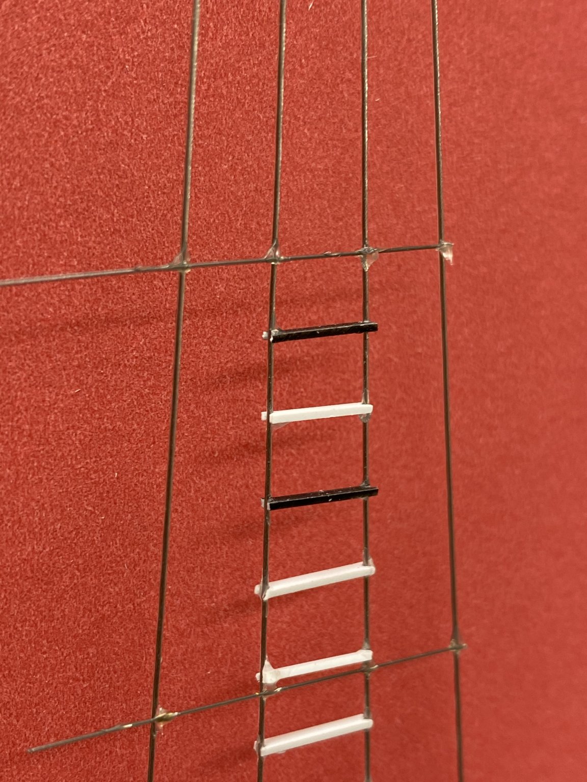
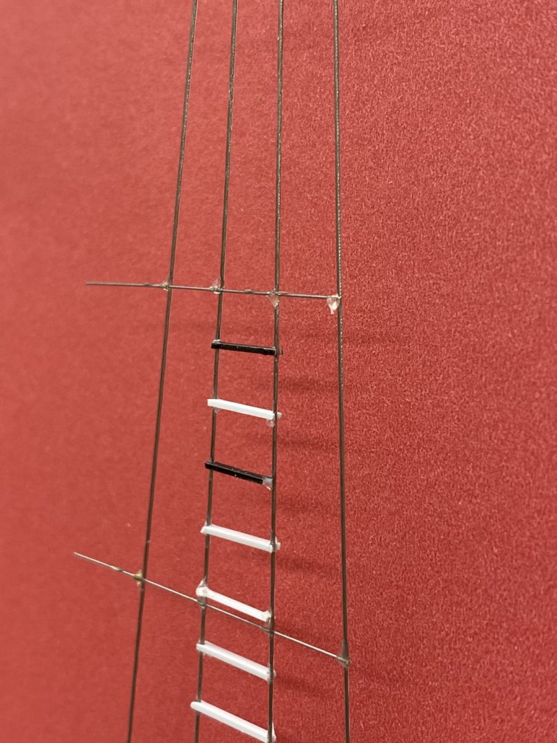
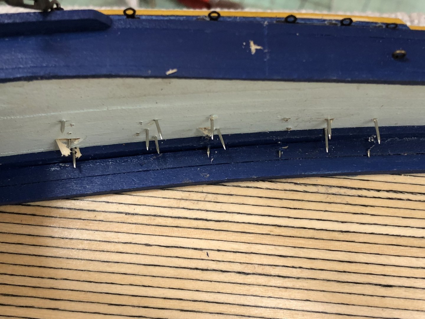
 I painted some of the styrene black. The first attempt using Badger acrylic paint did not go too well so for the second try I ran the styrene over some 400 grit sandpaper before painting. Seemed to adhere better with a slightly roughened surface. I added two black steps to see if I needed to change procedure. The problem was it was harder to cut the "V" in the step - black surface and a basically black blade (No 11 but not a genuine Xacto). I will get some chrome blades before I start this in earnest. Procedure is the same. Based on these examples I think a touch-up with black at the ends of the steps is gping to be required. see for yourself. One more procedure change - I will glue the piano wire only to the outboard shrouds - the glue drops on the inboard shrouds getsin the way when I add the steps. It probably wouldn't hurt to paint the piano wire black as well, before gluing it to the shrouds. May need a touch-up on those glue blobs too. I also got the port side chain plates and molding installed. Some paint touch-up is still needed but we are basically ready for the turnbuckles.
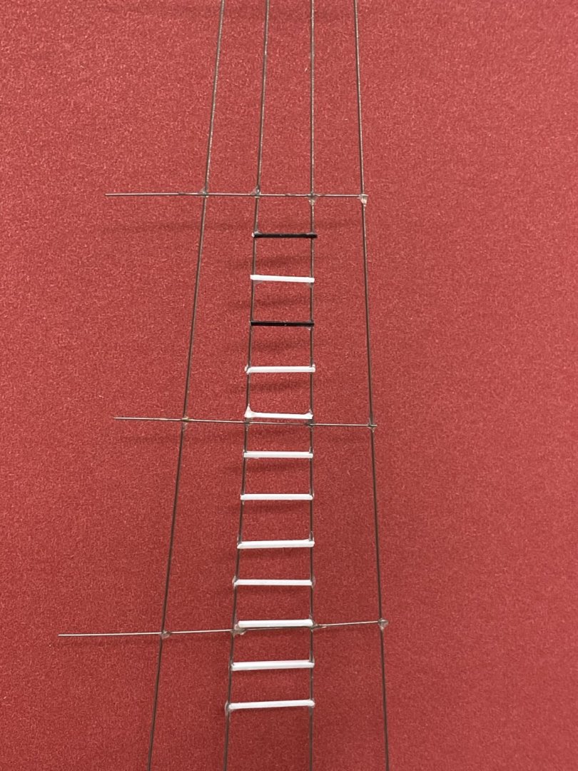

- 144 replies
-
- 3
-

-
- charles p notman
- finished
- (and 1 more)
-
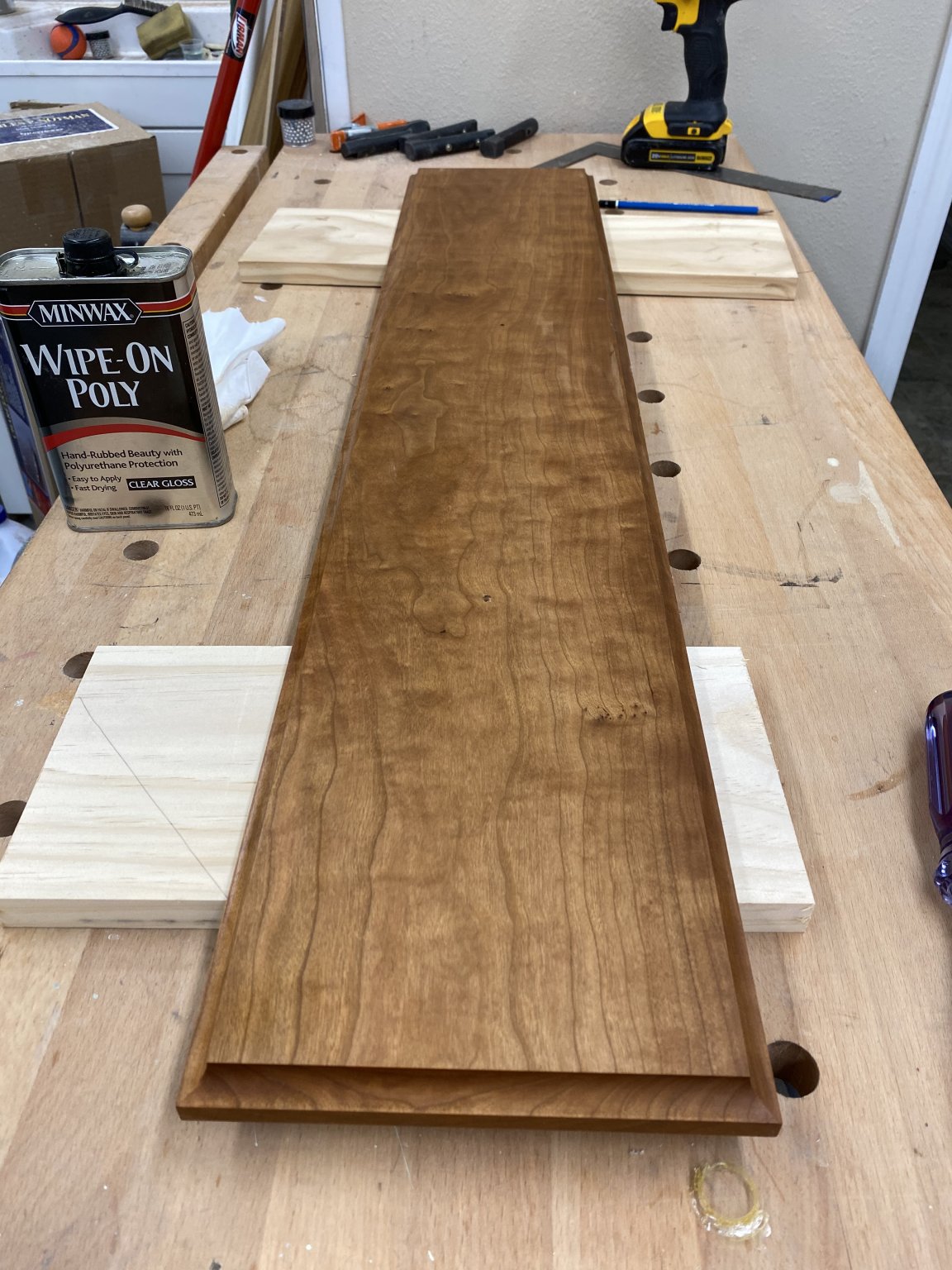
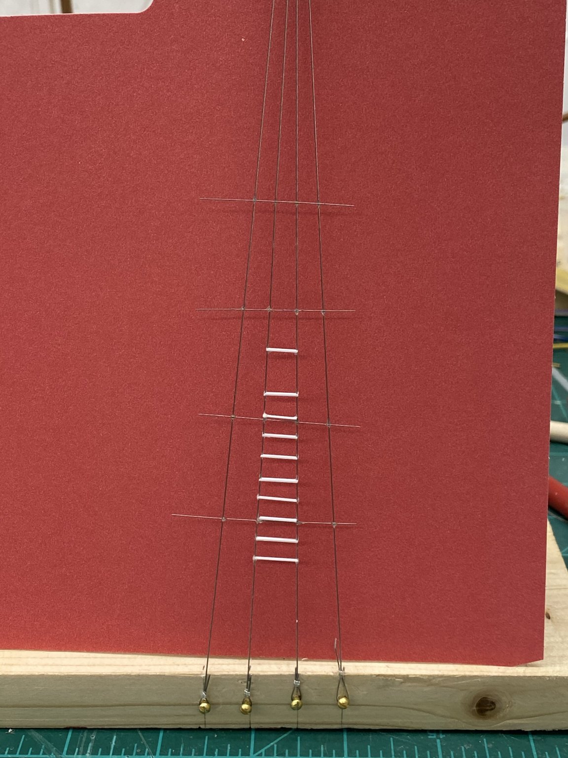
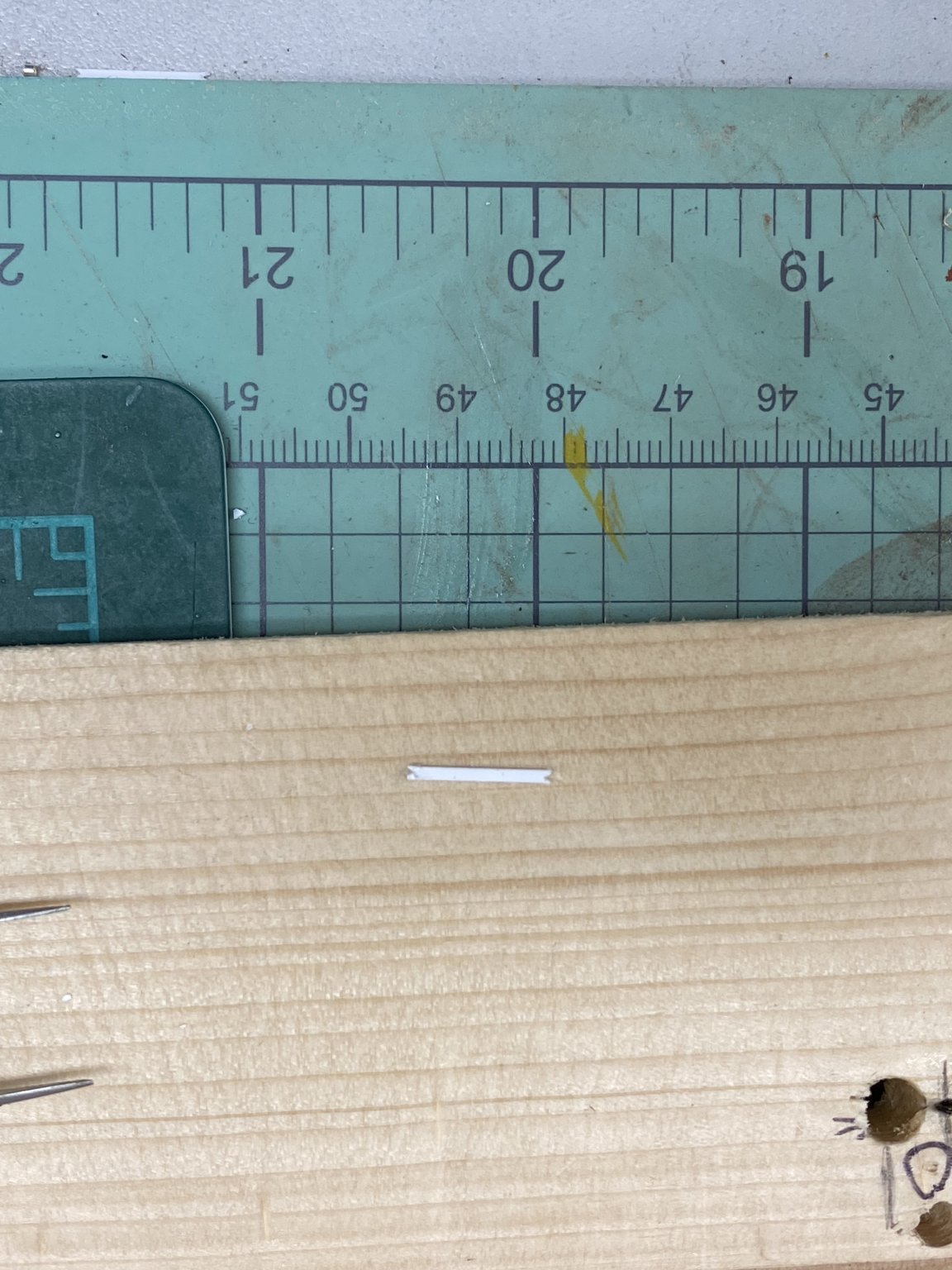
Deck access hatches dry fit (more or less the correct locations). Here is the display board after its first coat of Wipe-on-Poly (gloss). It appears this will be at least a 3-coat job, probably more. And now for the "real fun". I decided to build a prototype of the lower shrouds to see what "issues" might arise since using the Beadalon nylon coated wire is somewhat outside what I am familiar with. I did use Beadalon wire once before but it was on a 1/35th scale model without ratlines (or steps). Plus I have never tried to use styrene in the shrouds. So I got a scrap of wood, a 5/16" dowel, the shroud template for the kit and built a mast with small wood screws where the shrouds would tie off. So far so good. I rigged the two sets of shrouds to one side and discovered that I had to get all four shrouds tensioned together rather than doing them one pair at a time. When on the real model I plan to get all four pair (both sides) rigged and tensioned before I squash any of the "beads" that crimp the wire together. It is easy to get one pair tighter than another which causes "droopy" shrouds which is "not good". The next problem occurred when I tried to add the styrene "steps". Initially I thought to use the liquid styrene glue that seemed to work well when adding the styrene to the deck houses. Alas, I do not think there is enough surface (it is only .020" thick) bearing on the shroud to form a good bond. That and it is very easy to distort the shrouds if you try and wedge the step between the shrouds. Shroud distortion lead to my next step. Given that you are going to have to cut the stairs to pretty exact dimensions (generally by trial and error) I thought that having something fairly rigid at every fifth stair as the plans show could help to keep the shrouds aligned. I searched and found some .010" music wire (I think it is really a piano string) that I was able to use. I put a drop of Weldbond (my glue of choice) on each shroud and laid (I had the mast horizontal) a short piece across the shrouds. When the glue dried I had a fairly stiff connection across all four shrouds. For the test I did four sets of wire. Then I tried adding the steps, although I used the styrene without painting it black. This is when I discovered that the styrene cement was not going to work. So I used the Weldbond here as well. I cut a very small "V" in one end of the styrene and then engage that "V" on one shroud while holding the step in tweezers and mark the length. Cut the step and cut a small "V" on that end. Here is a shot of a step ready for a trial fit. Now the tricky part. Engage both "Vs" on the shroud and see where if it fits. When there are several open places if it does not fit where you intended try one of the slots above or below depending on whether it is too long or short. If that does not work, either shorten it a bit or try again. When you have a fit (no shroud distortion) then put a drop of Weldbond on the shroud at each end and carefully engage the step on the shrouds and the glue drops. When the glue has set some I add another drop on the outboard sides of the step/shroud for insurance. Here is my test mast with four wires and ten steps - this took almost two hours to complete so; 240 steps looks like 48 hours of work. Hopefully I will get faster but probably not much. It is really hard to get the measurement right the first time. I do not think I got even one of the ten I did correct on the first attempt, except where I used it somewhere other than where I had measured. I know it does not look level but the template I used (copied from the plans) was attached so the the template shrouds and the mast shrouds lined up which made things off just a bit. Getting the wire on straight would have helped. Using the painted steps will probably require a paint touch up on each end of each step as once you cut the styrene there will be "white showing". I will have to see how much this shows through the glue drop.


- 144 replies
-
- 3
-
-
- charles p notman
- finished
- (and 1 more)
-
More odds and ends. Here are the aft bitts and mooring cleats - test fit; not glued down yet.

-
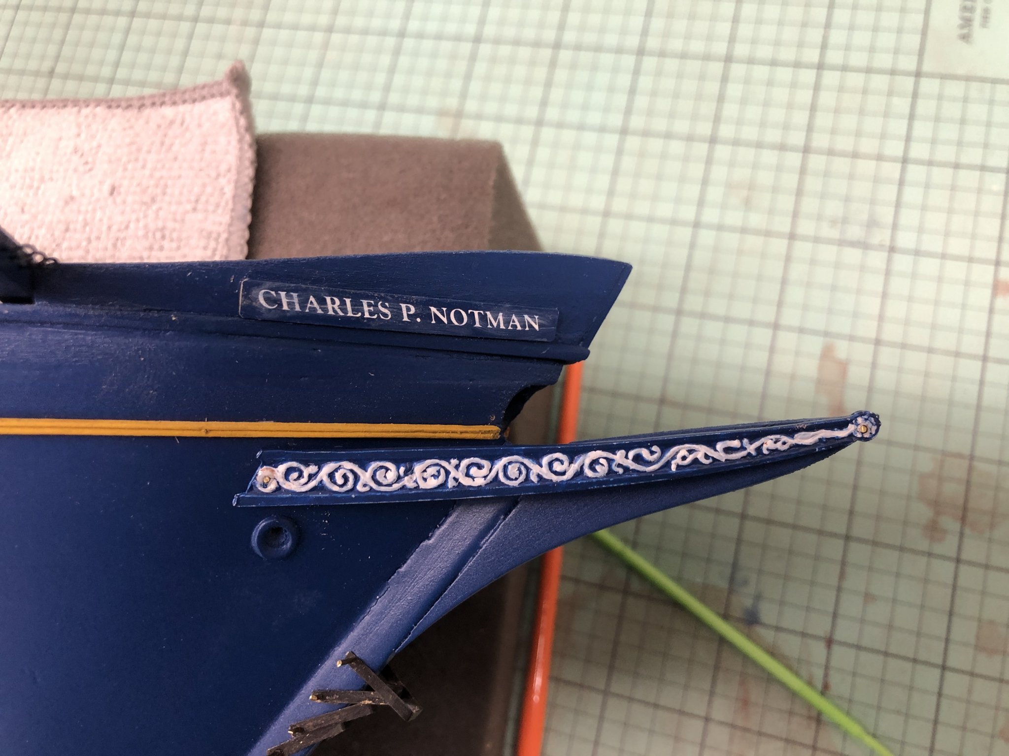
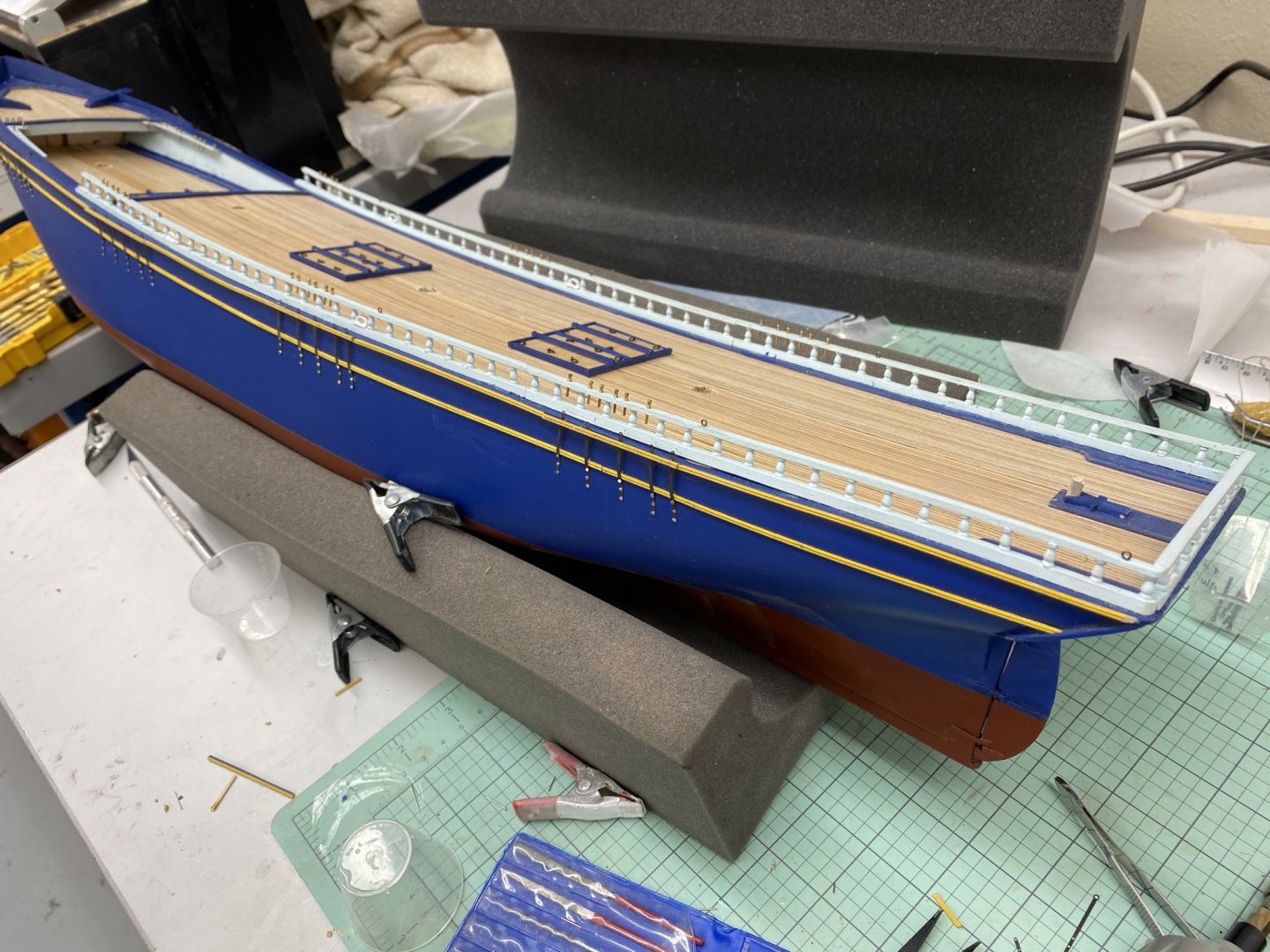
As promised here are two better pictures of the "double yellow stripe, here on the port side. Also I got the fore mast chain plates (both sets this time - I forgot the Fool and Cap stay chain plates on the starboard side) mounted but not yet cleaned up (blacken pin heads, touch up the bead molding, etc). I started to put together the davits and blocks for the ship's boat (although I am still on the fence about where the boat will go - in the davits or on top of the after house). The instructions would have me drill a 1/16" hole, 1/16" deep in the bottom of a 1/8" double block. Try as I might I found that close to impossible and still have the block capable of having lines passed through. The lower line holes would be obliterated by the 1/16" hole. My solution was first of all to use 3/16" double blocks (I had more of them that I could afford to destroy) and second to drill a #75 hole (.021") hole as dead center in the block as I could manage. I also cut the eye off the end of the davit (as instructed) and drilled a #75 hole as close to the center of what is barely .050 in diameter. (I would not even attempted this without a miniature drill press and x-y table.) I could not drill in very deep as even with the bit chucked with less than 1/4" exposed, the bit wanted to wander. I used a piece (a really short piece) of .020 brass rod and thin CA to join the block and davit. After that set I used thick CA on the outside where the two pieces join. Here is what one davit looks like after the block/davit was painted (twice). (Still needs some touch-up.) I used a similar technique to join the pieces of the Main fife rail together. I had no luck trying to make a good joint between the bitt post and the pin rails. I used the .020" wire and drilled all the way through the bitts then into the pin rails. I used a piece of thin plywood as a base to hold things while I assembled the pieces - I believe the plywood will come in handy as a template to mark where to drill the holes in the deck when that time comes. I plan on making similar templates for the Mizzen and Spanker pin rails.


- 144 replies
-
- 2
-
-
- charles p notman
- finished
- (and 1 more)
-
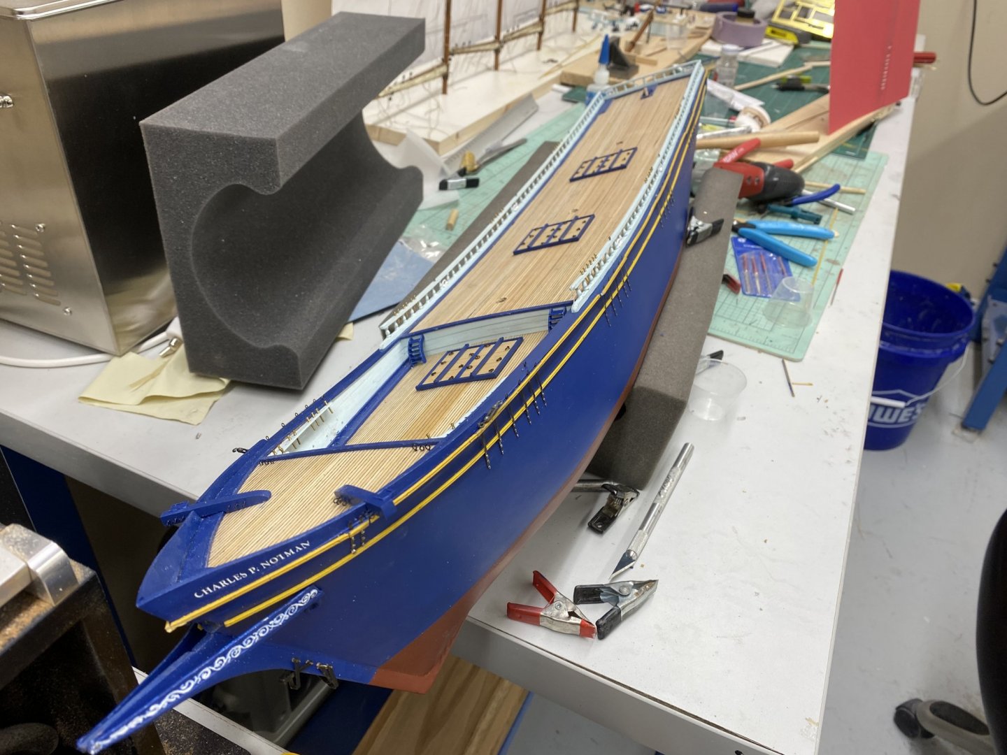
I got the chain plates on the starboard side and added the double bead (painted yellow like the sheer strake) between the chain plates so now there are two yellow stripes down the side. The picture does not show this very well but I will work on getting a better picture when I get the chain plates on the other side done. I got an iPhone 11 Pro today so the pictures will HAVE to improve!
- 144 replies
-
- 1
-
-
- charles p notman
- finished
- (and 1 more)
-
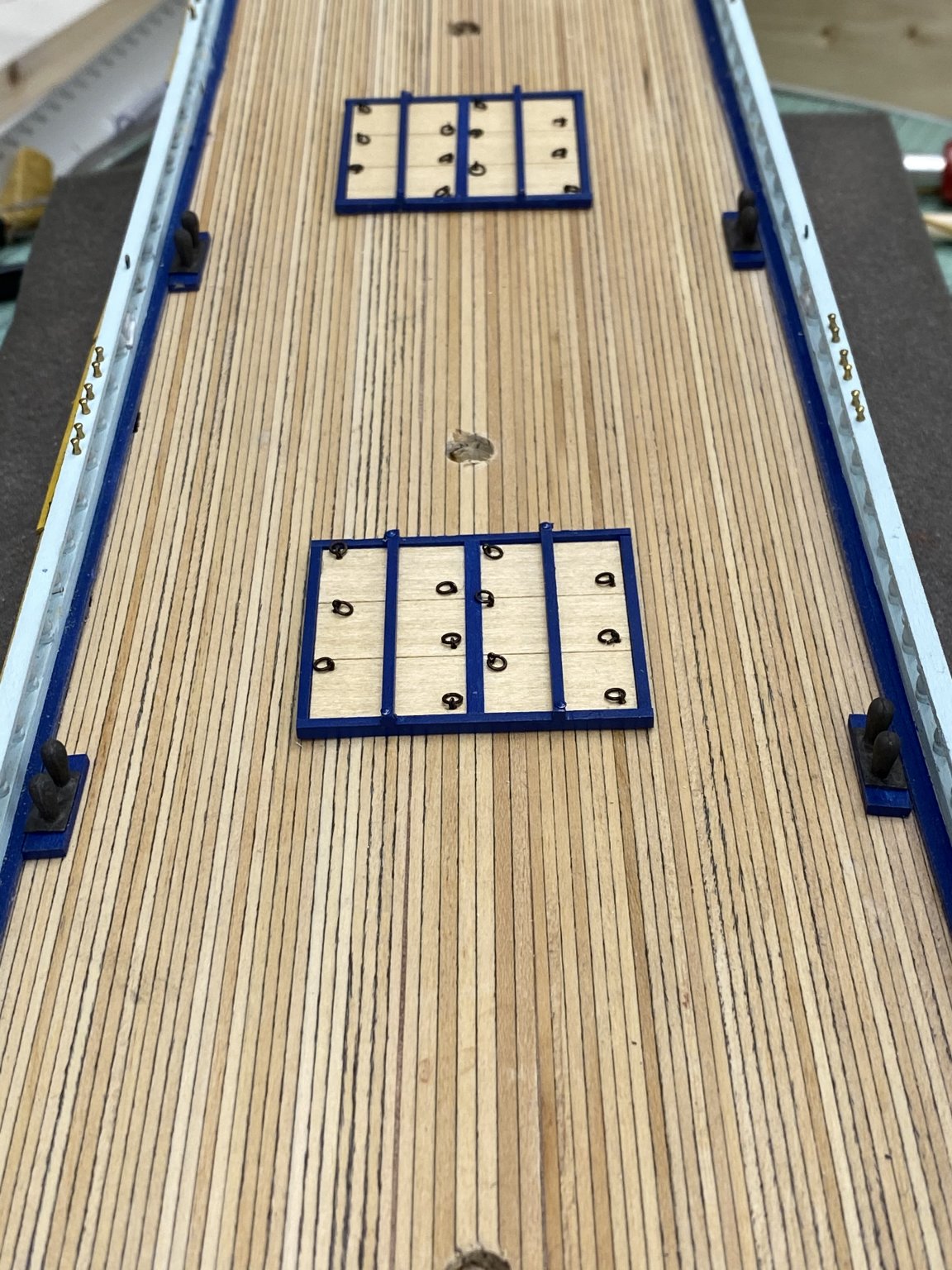
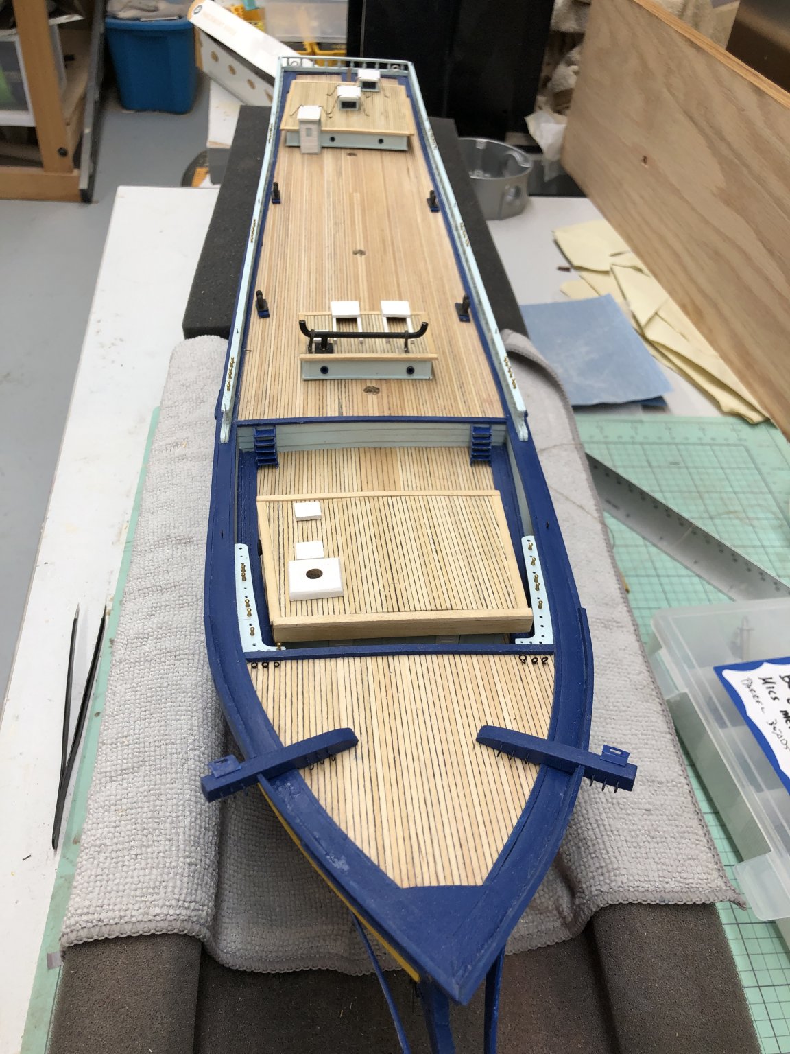
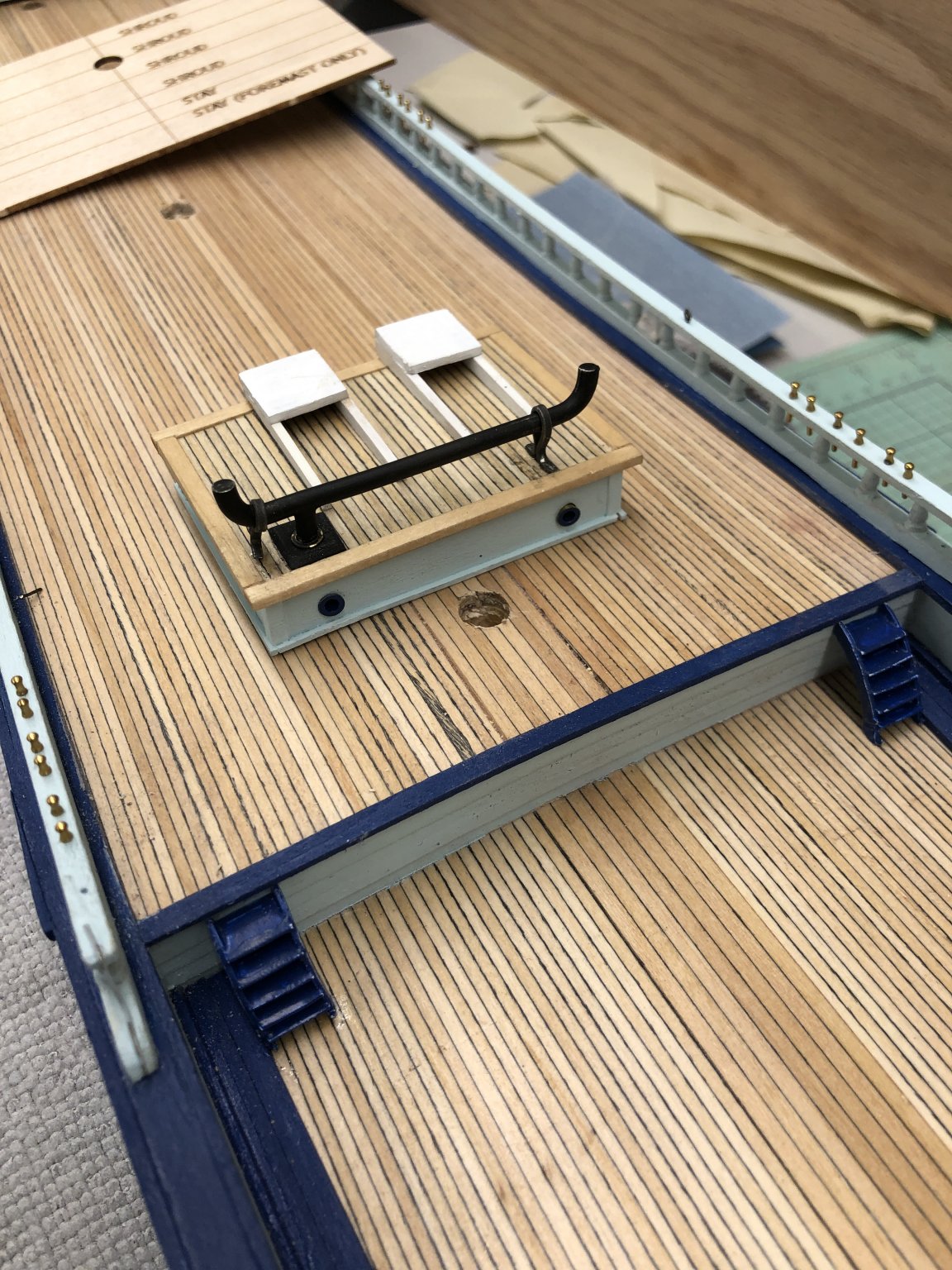
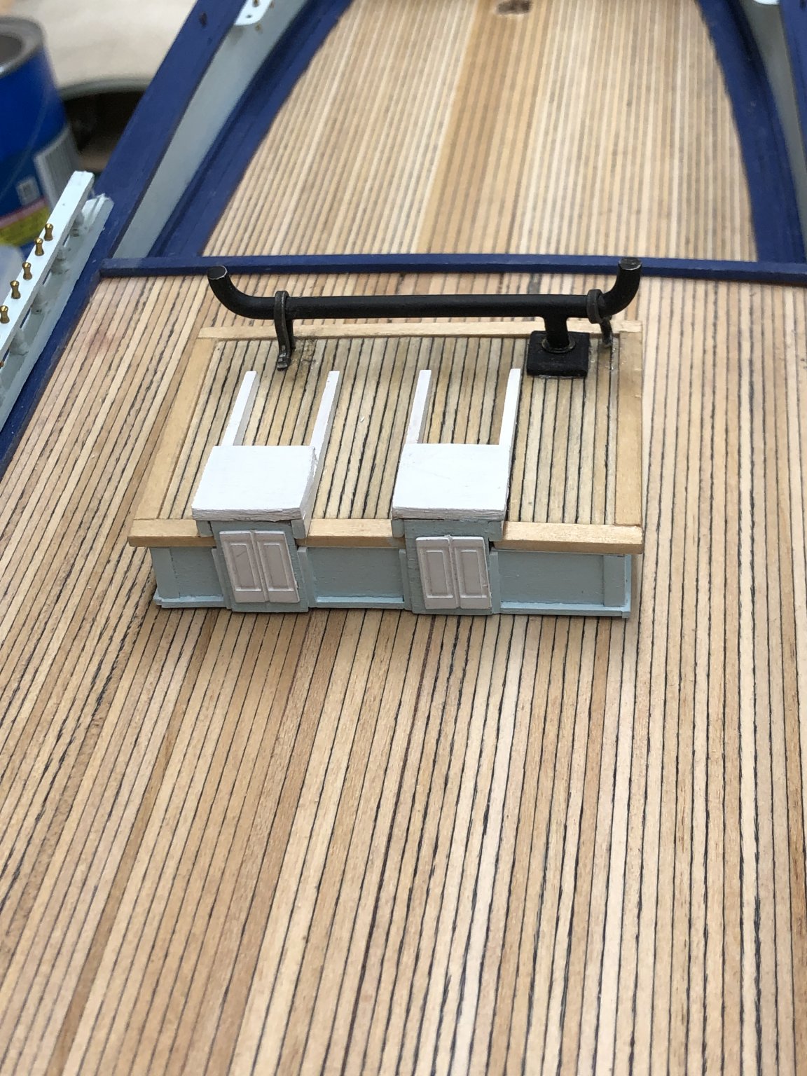
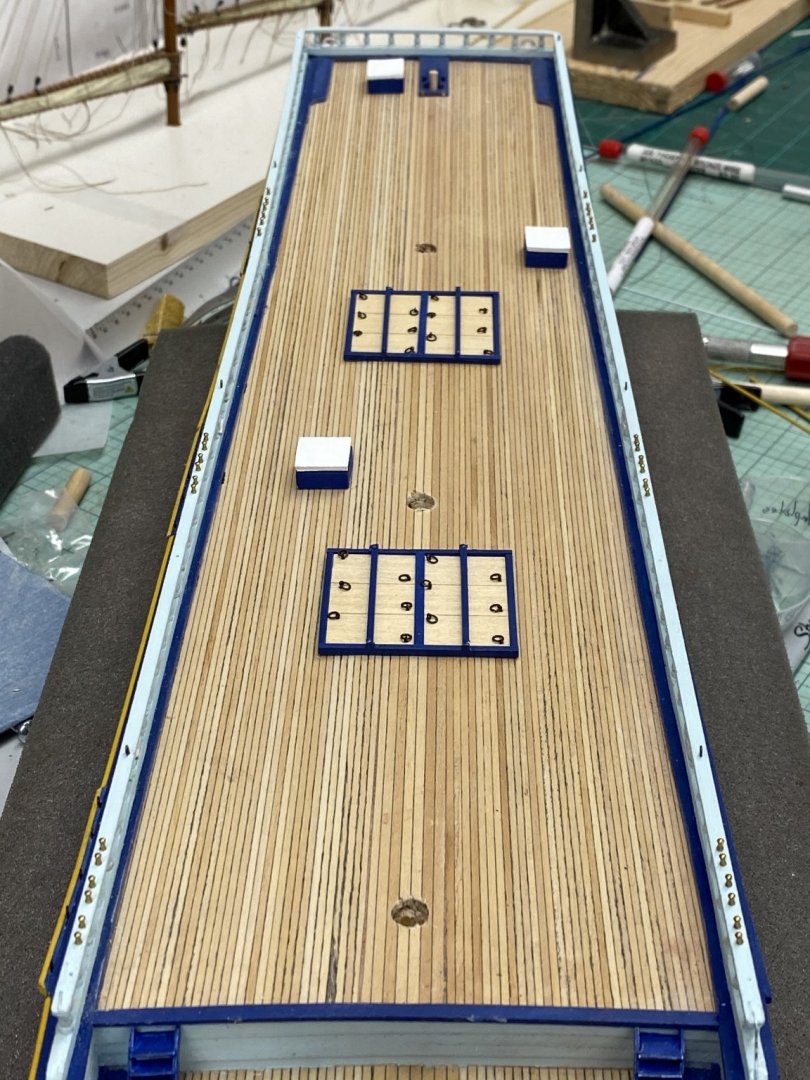
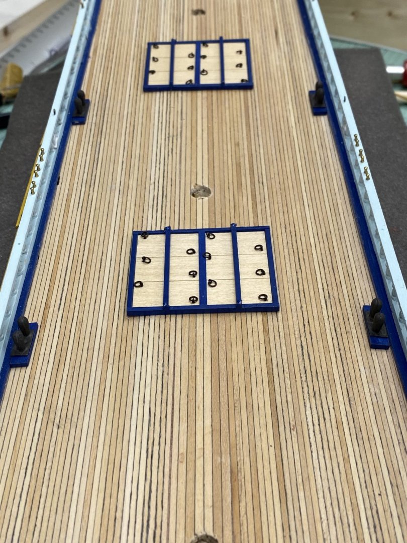
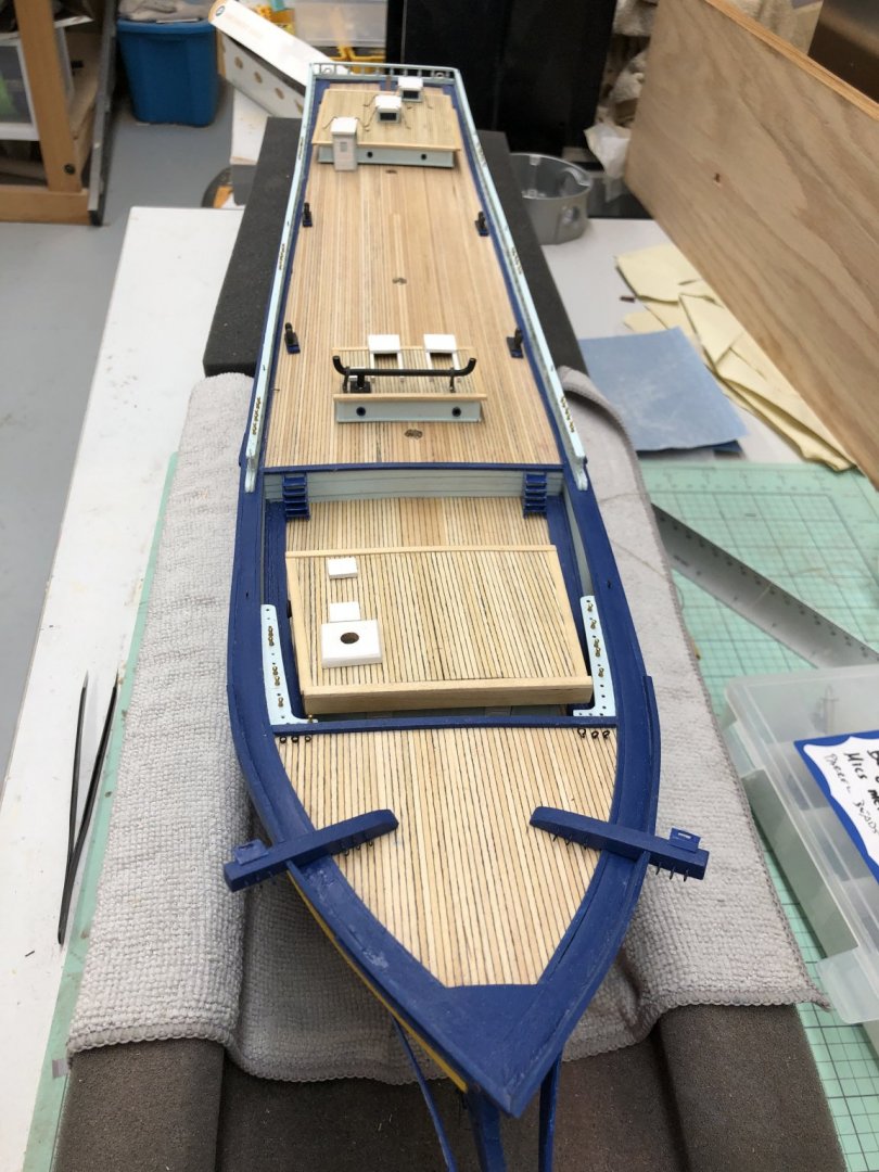
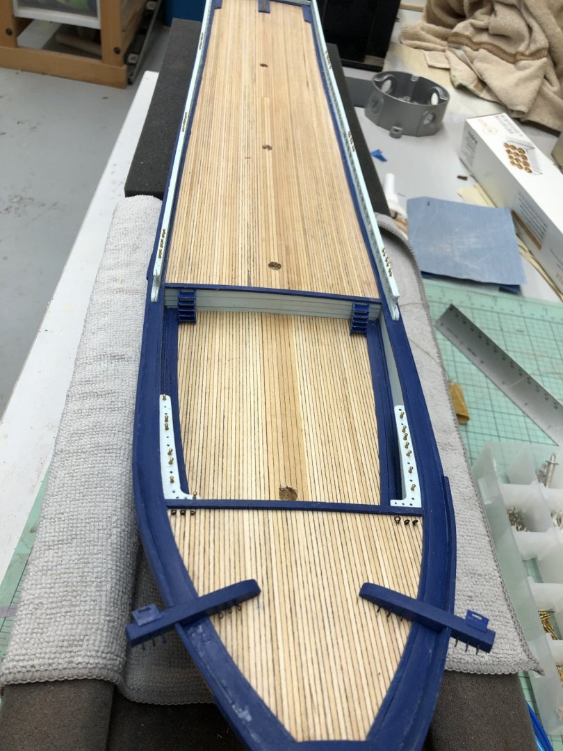
Hatches are finished and installed on the hull - the first of the deck furniture. (The steering box is just there for a dry fit.) The instructions call for using pins through the strong backs to assist in holding the hatches down. I think in the future (like for the chain plates) I will lightly sand (I have a 240 grit sanding disk on my Dremel handpiece that I use to clean up the Britannia metal parts) the heads of the pins to make it easier to paint them to match. It took two coats on the hatches - two opportunities to paint somewhere it does not belong.

-
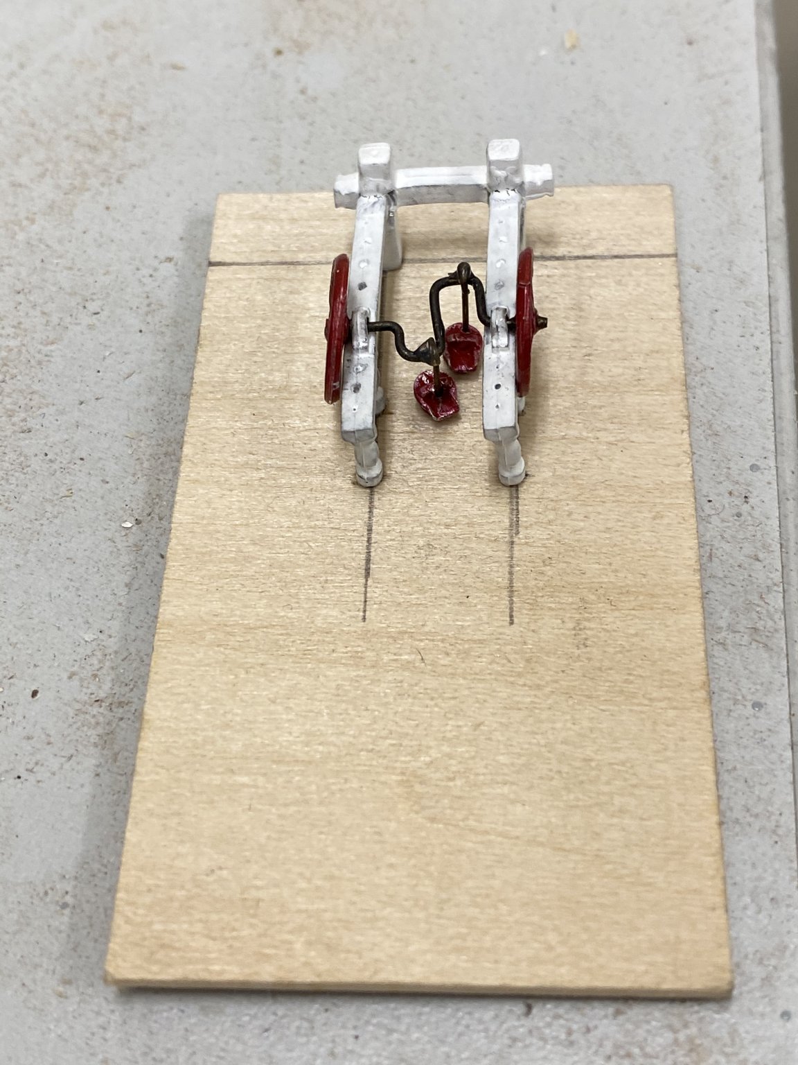
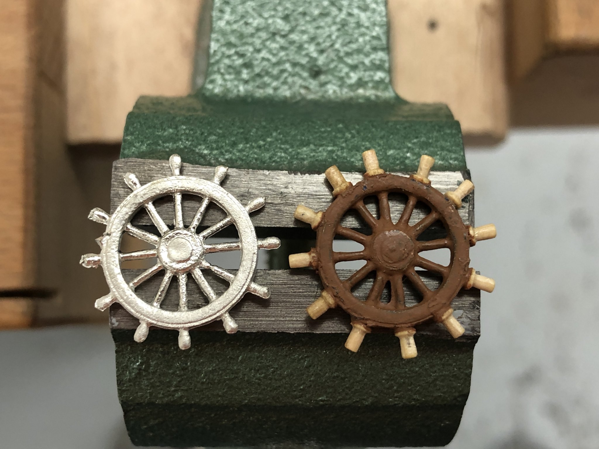
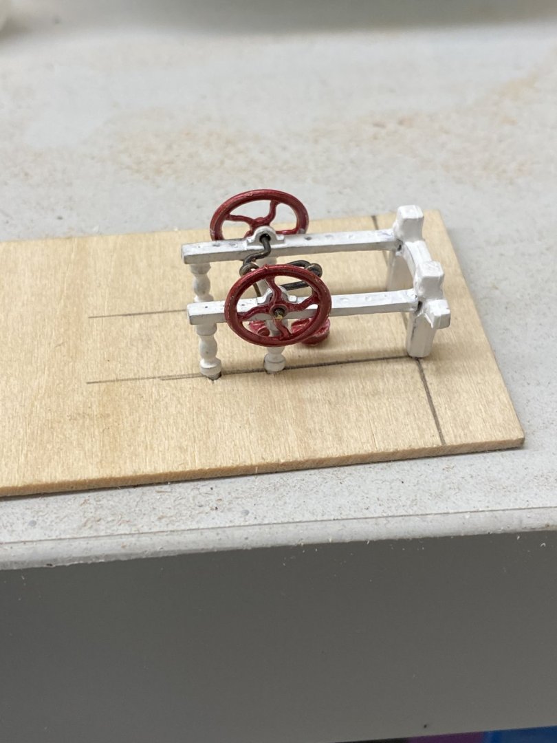
The steering wheel saga continues. I finally figured out that the wheel I showed in a previous post was NOT the one that came with this kit - it was left over from something else. The wheel on the left below is the one that comes with the kit. The one on the right is the kit wheel with boxwood spindles that were created from boxwood 6mm belaying pins. I used the technique that is included with the Syren ship's wheel kits - using the Dremel hand piece as a mini-lathe to turn the belaying pins down to about .04" - that is still pretty badly out of scale but trying to go much smaller drives up the scrap percentage a good bit. Here is the technique for mounting the new "spindles". I filed kit wheel down to "smooth" metal on the rim and then mounted the new spindles to line up with the existing spindles on the inside of the rim. I repainted the wheel internals a "rust" color and put a coat of flat finish on the spindles. I could have tried to paint the outer spindles on the kit wheel a different color to try of the same effect - it certainly would have been faster - but this seemed a better solution IMHO.
-
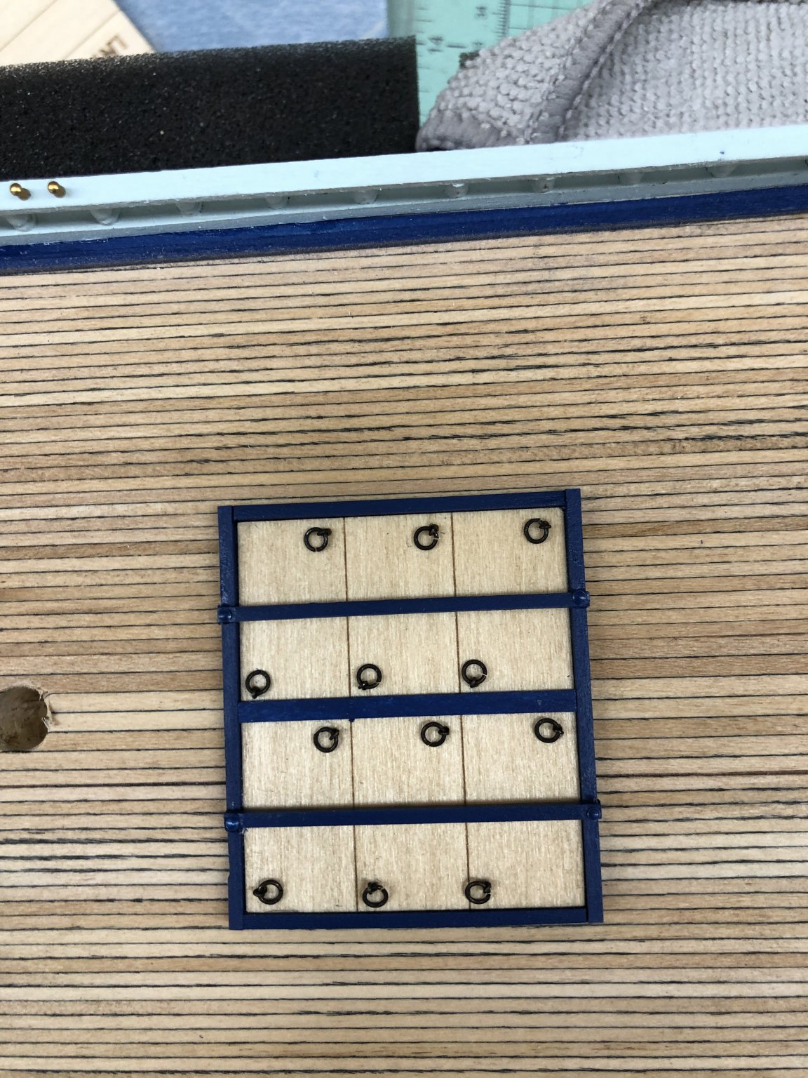
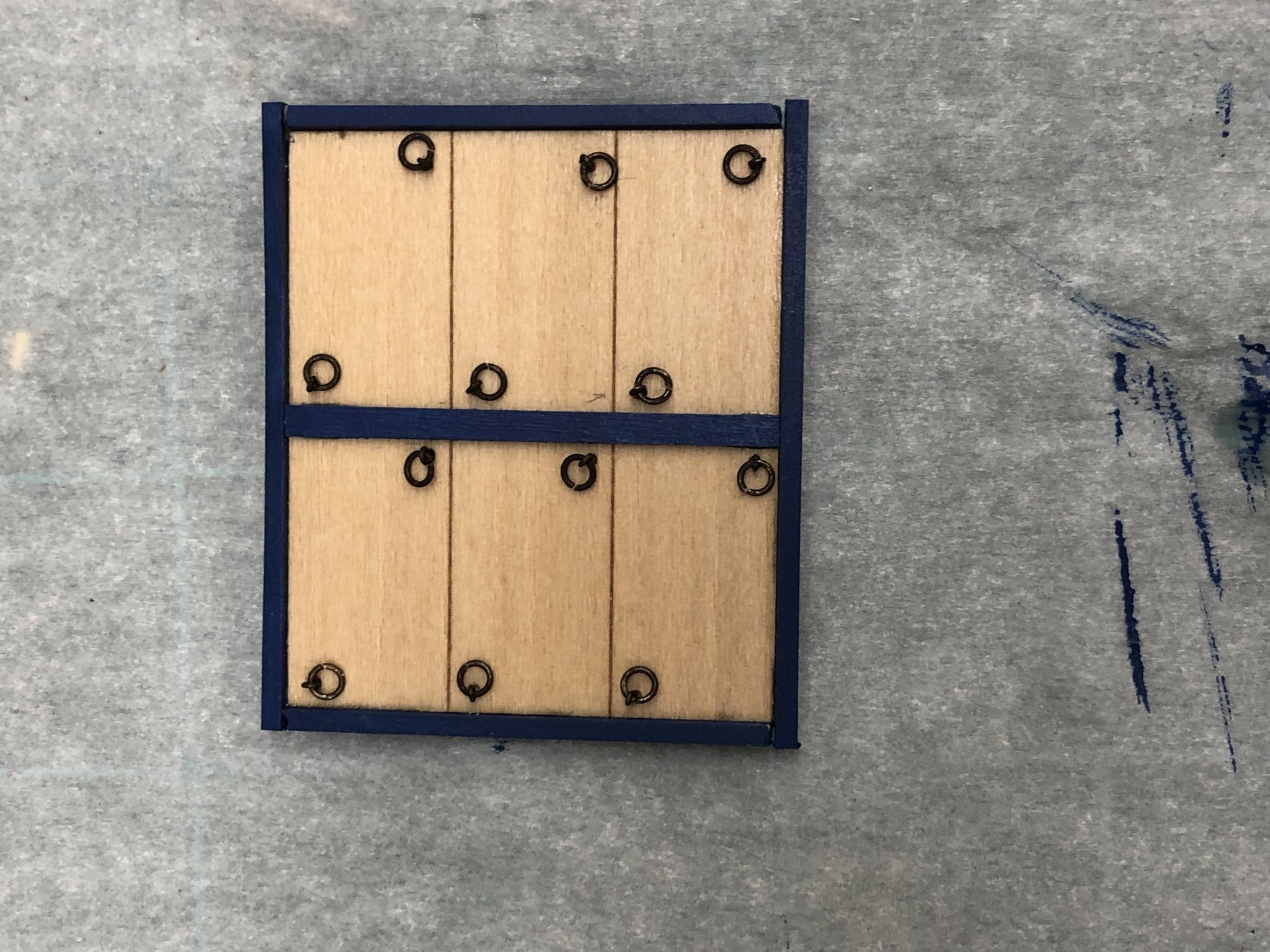
Working on the hatches too. Pretty straightforward all in all. I would have thought they would have mitered corners but not according to the instructions so who am I to add effort that will likely never be noticed. Here is one of the hatches complete except for the strongbacks. I used 3/312" eyebolts (Model Expo I think) and 1/8" split rings for the lift rings. It took most of the afternoon to get 32 of these assemblies put together and blackened. Trying to "unsplit" small split rings takes a good deal of concentration and two pair of needle nose pliers. I finally settled on using a drift pin punch to flatten the split ring and then the pliers to squeeze the joint closed (more or less). Here are the other 24 lift rings drying after being blackened.

- 144 replies
-
- 2
-
-
- charles p notman
- finished
- (and 1 more)
-
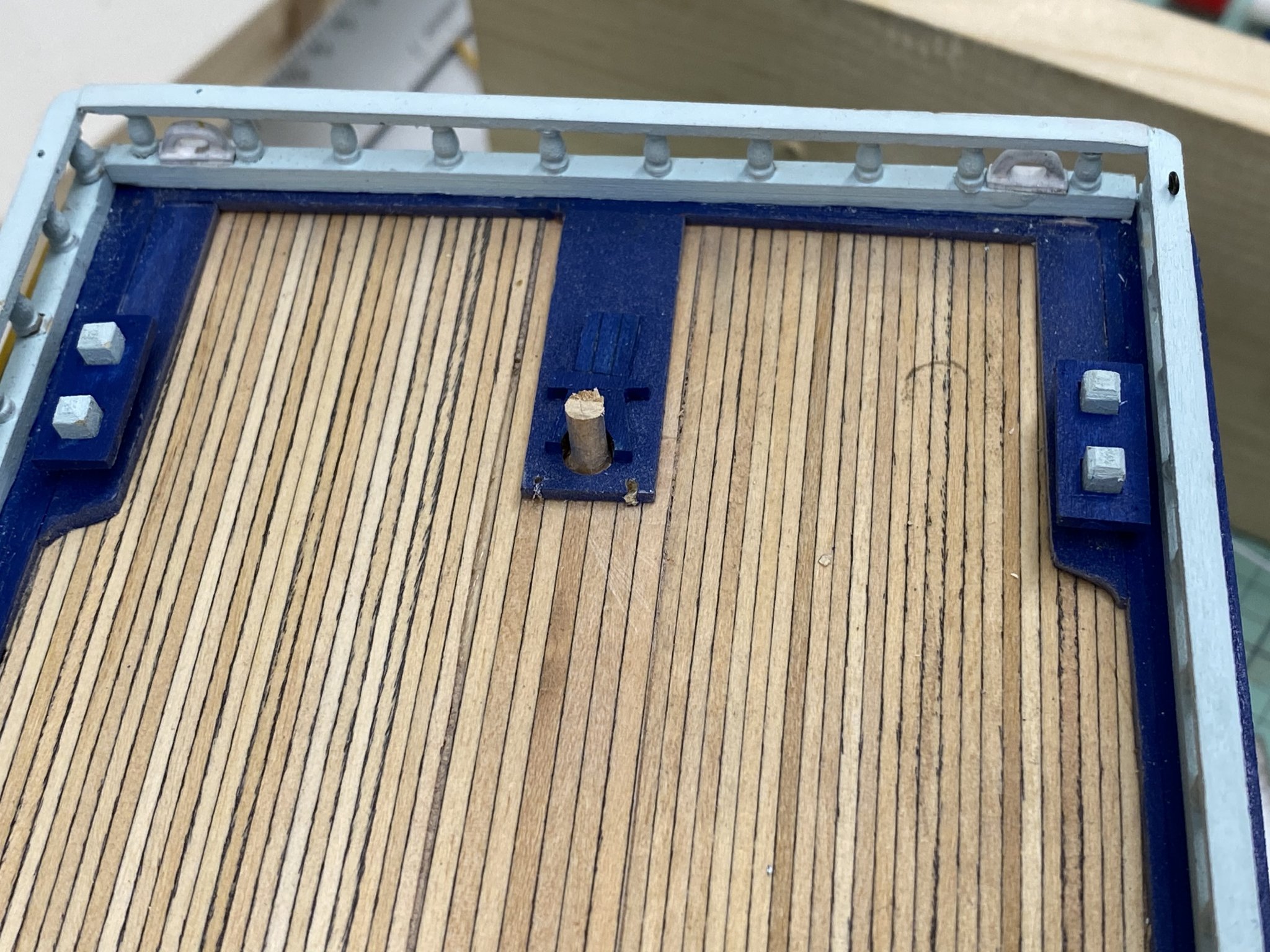
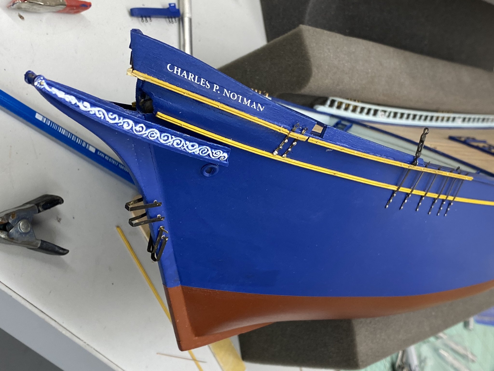
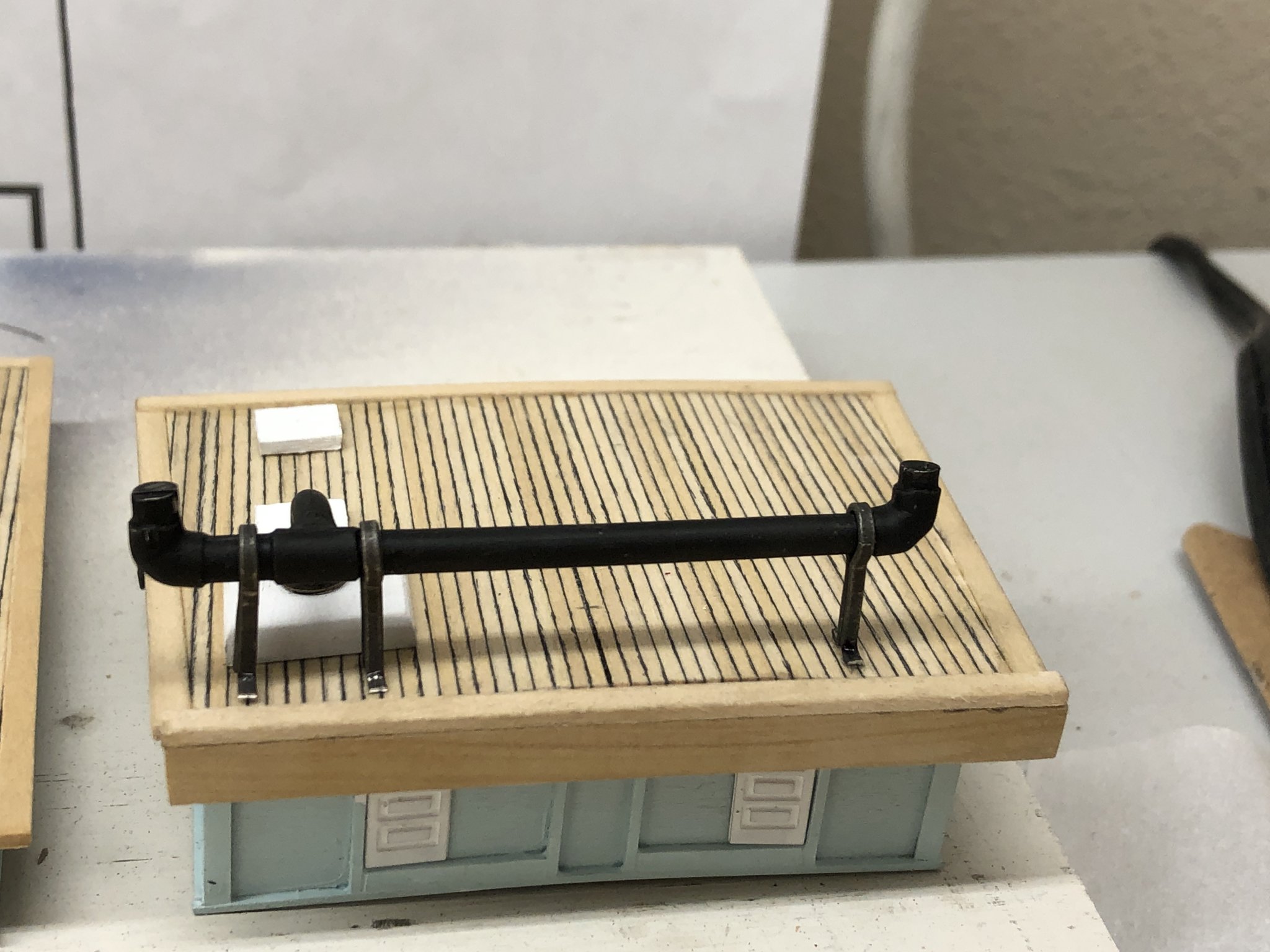
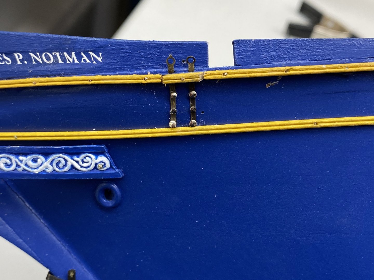
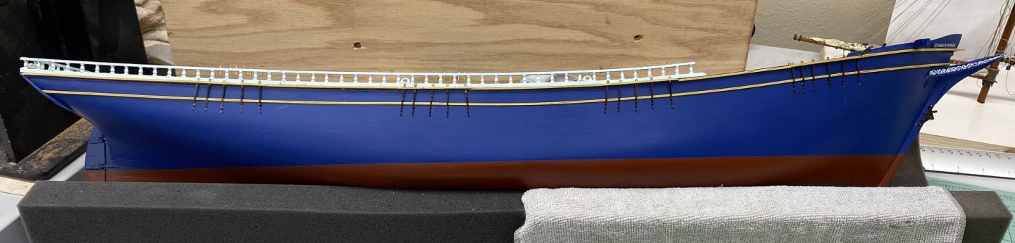
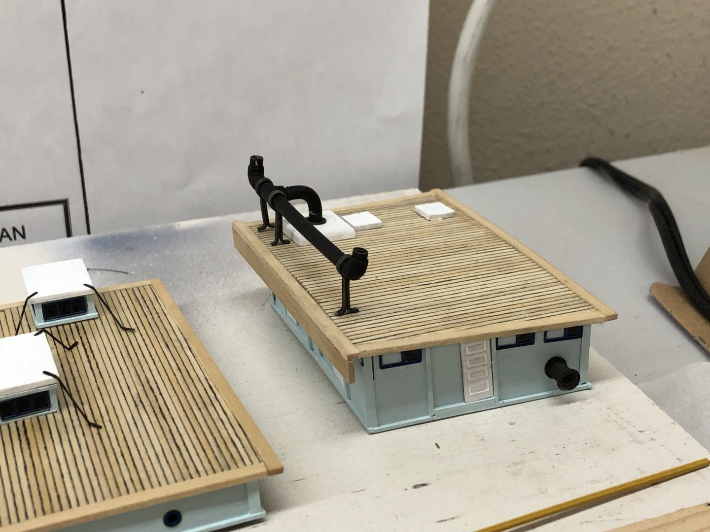
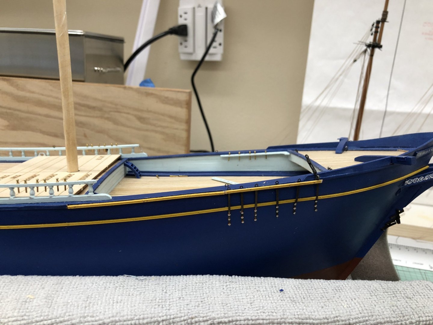
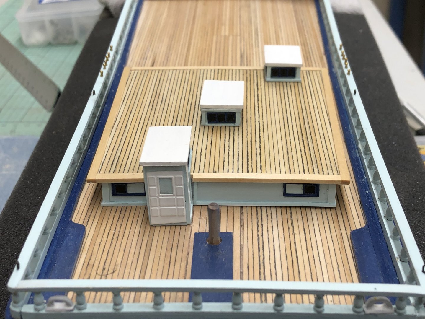
I am working several areas in sequence as I get closer to the "real work" of getting the hull ready for the mast installation. I finally got the boiler piping atop the forward deck house. Much easier if you plan ahead for the boiler stack supports rather than trying to do them "as you go" which I did with the stove stack. Here is the forward deck house with the boiler stack installed. I still have to install the fore staysail sheet and lead block. The drawings are not all that clear on the configuration of the fore staysail and jib sheet tackle. I am going to use a double 1/8" block with becket on the booms and a double 1/8" on the deck with a single 1/8" fairlead block to a cleat on top of the forward deck house for the fore staysail - the jib sheet belays on the forward most pin on the starboard side forward pin rail. We will see how easy that turns out to be. I decided to start putting the chain plates on the hull since they are going to be needed shortly. I also decided to put a second row of the double bead molding (painted yellow) at the deck edge. The double bead molding is used as the out layer over the top of the chain plates so I will paint this yellow and continue the yellow molding along the outer edge of the deck. I would assume there would be some kind of rub rail at the extreme hull breadth and this is what I am using for that. Here is forward starboard chain plates - before the pin heads are painted. What is not mentioned in the instructions is that the pins provided in the kit are long enough to punch through the bulwarks above the main deck. It will be really hard to see this as it will be hidden by the forward deck house but it would have been nice to know about this before hand. I will cut the excess off and try and clean up the splinters before the deck bhouse goes in. Because the forward most chain plate is outboard of the splash rail I installed the turnbuckle now as there is not much clearance to do it later and the chain plates are pretty fragile (.010" thick) so it made sense to put this one on now. You can see the continuation of the bead molding aft of the forward chain plate. Some touch up painting is required where the molding and chain plates meet.-

- 144 replies
-
- 1
-
-
- charles p notman
- finished
- (and 1 more)
-
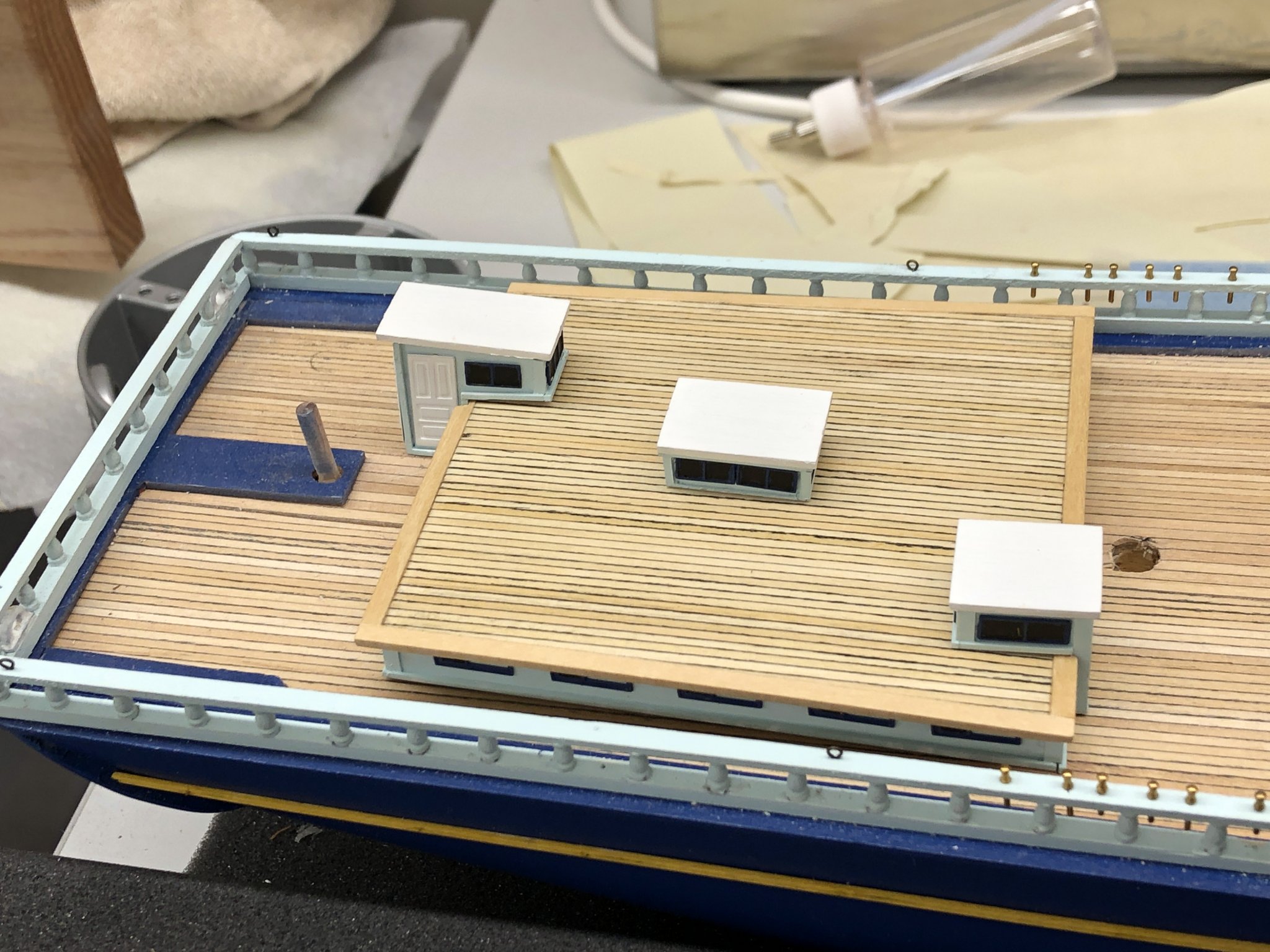
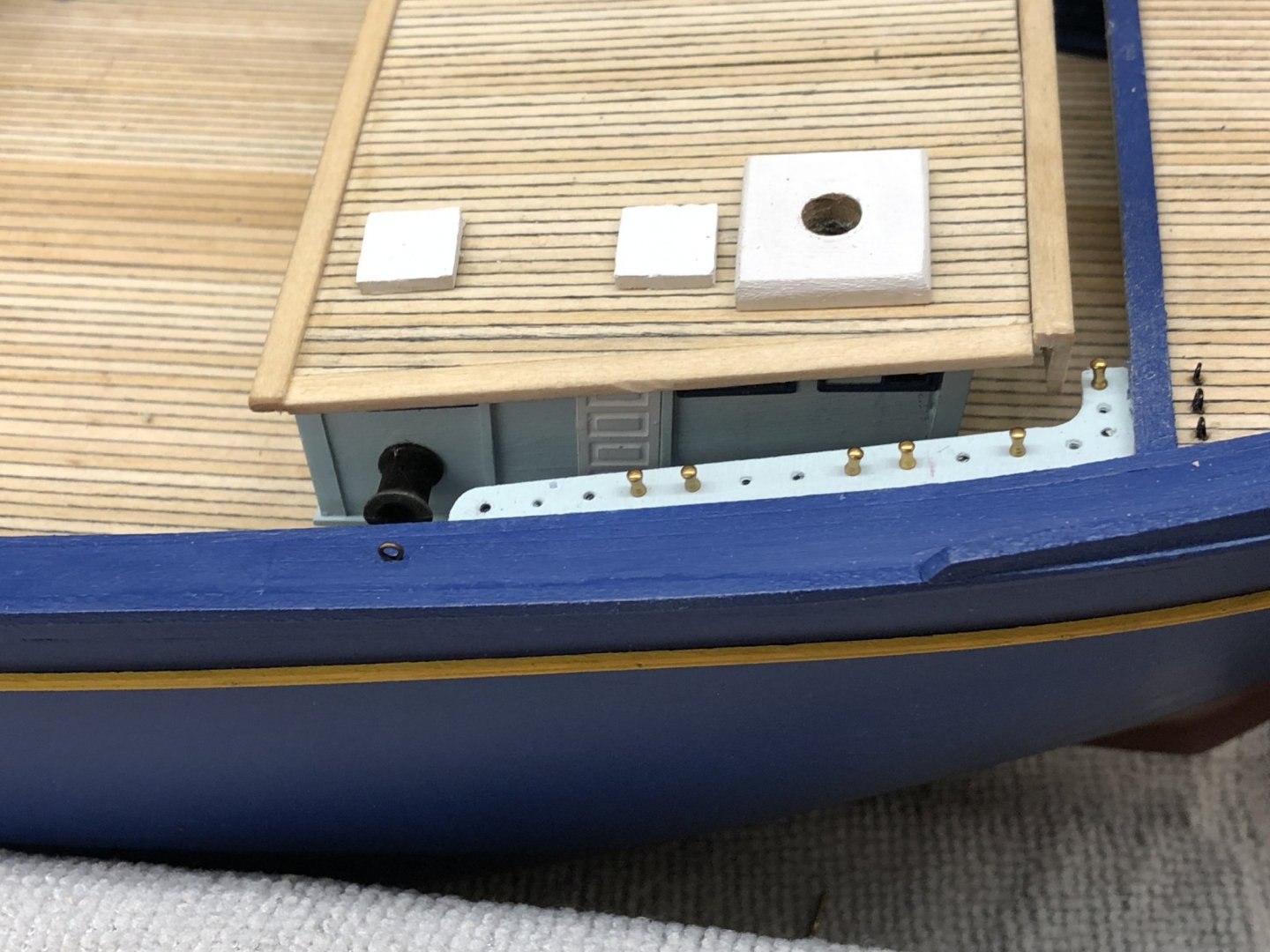
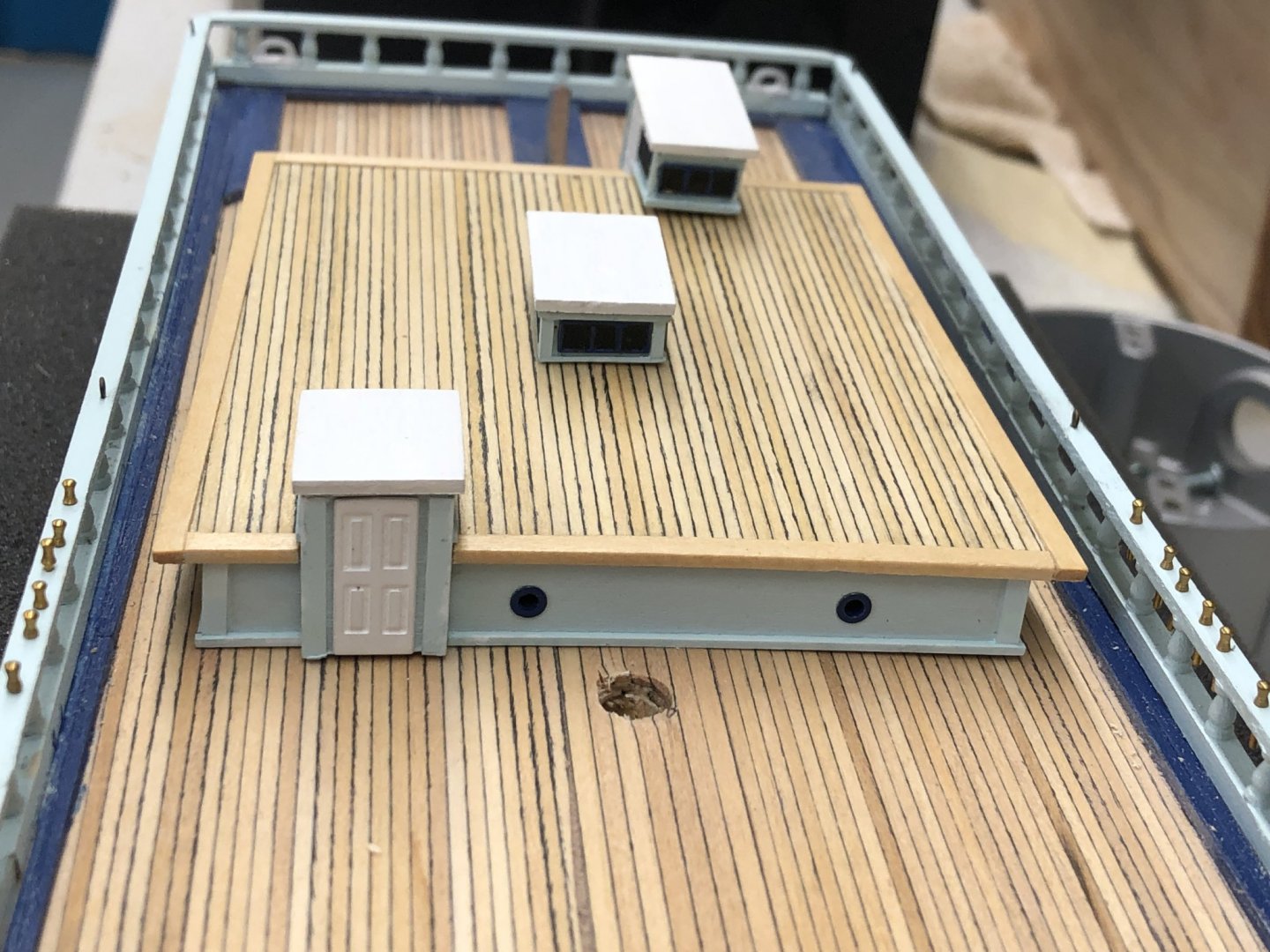
Forward deck house is complete except for the boiler piping and some of the deck pads and cleats. I finally gave up trying to glue the two pieces of the boiler stack together directly and used a piece of 1/32 brass rod drilled into each piece to hold it together (plus Thick CA). That has worked so far. Based on my experience with the cook stove stack on the midships deck house I plan on building a jig to get the three stack supports the same length before they go on the stack. I am hoping it will lead to fewer "cut and fit" sessions and a cleaner looking installation. So here is the hull with all three deck houses in place (more or less) and a shot of the side and rear of the forward deck house. It is easy to see why they had sliding doors on the forward deck house. It looks really tight in there. I am not sure how I am goiing to get the lines secusred on the pin rail. Should be much fun. May have to leave gluing the deck house down until I have gotten the lines around the belaying pins.
- 144 replies
-
- 2
-
-
- charles p notman
- finished
- (and 1 more)
-
Midships deckhouse is done. Should have the forward house done tomorrow so I can start on the hatches and smaller items. I also got the "anti-fouling irons" (I assume that is what they are - keep lines from fouling on the structures on top of the after deckhouse) installed on the after deckhouse. I have not decided about the gangway yet. I am thinking about putting the boat on top of the after deckhouse instead of hanging on the davits. Less work, only have to paint the hull not do anything on the inside. I am telling myself that I will get a "real" ship's boat (one made from wood instead of Britannia metal) to hang on the davits someday. But...


- 144 replies
-
- 4
-
-
- charles p notman
- finished
- (and 1 more)
-
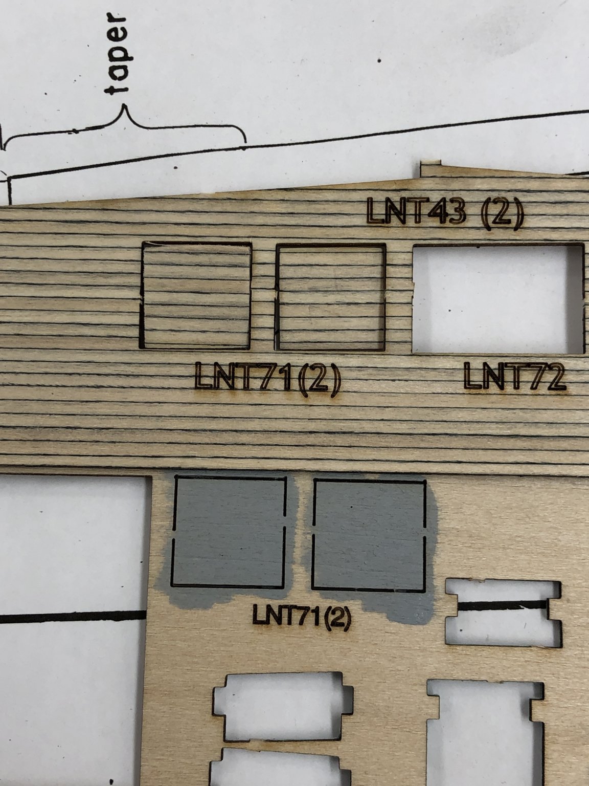
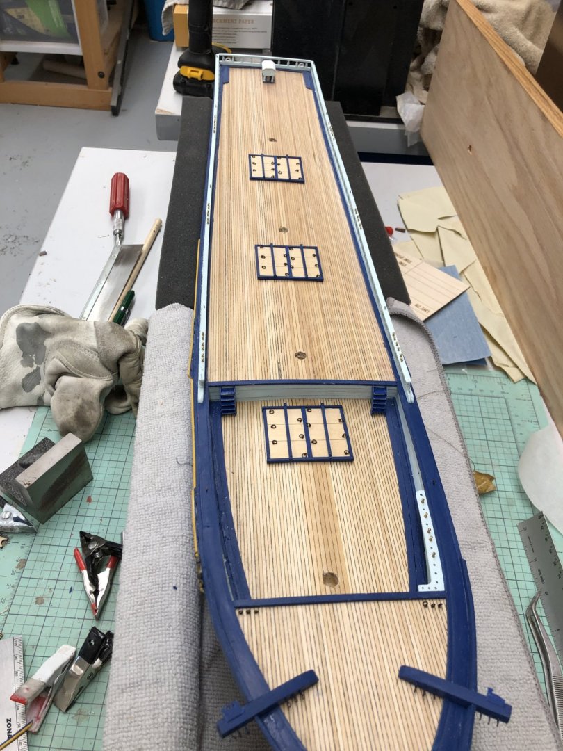
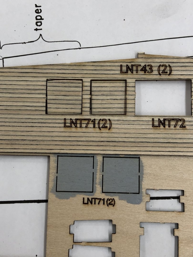
Note to future builders: It is not mentioned in the instructions (at least I do not remember seeing it) but there are two sets of hatch covers for the companionways/skylight. There are there three on the aft deck house and two on the midships one. They are shown on the parts list as LTN71 (2), LTN72, 73 and 74. One set is on the glued up decking sheets and the other on the plain basswood sheets. So you have your choice of using painted hatch covers or ones that match the decking material. Had I noticed this earlier I might have opted for the decking but am not willing to "change horses in midstream". Below is a shoot of both the LTN 71s.
-
Mike, Thanks - I can afford to spend as much time as my girlfriend will permit (as long as she is working on her quilt(s) I can do pretty much as I wish). We should get together sometime - Mt. Dora is less than 90 mi from Rockledge.
-
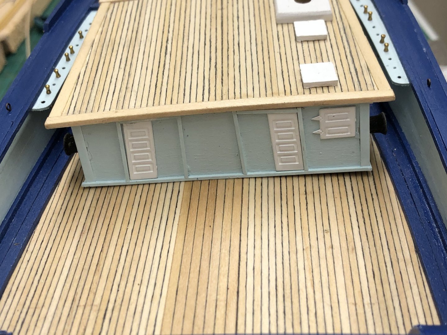
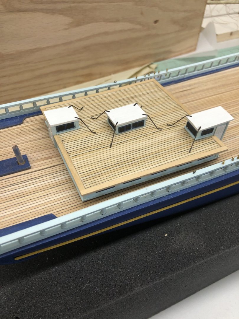
With the spars complete it was time to work on the deck houses. I decided to start with the most complex (at least is has the most structural pieces) - the after house. It went together pretty much per the instructions with one notable exception. Although the drawings do not explicitly show the styrene angle pieces being used on the companionways and skylight structures I used them to cover the joints where the sides come together. That turned out to be a mistake as the Britannia metal windows are too long to fit inside the styrene pieces in the ends of the companionways and all four sides of the skylight. I had to cut about half of the sides off the angle pieces to get enough room so the windows would sit against the wooden side material. It did not turn out too bad in the end but I should have looked more carefully at the drawings. Had I dry fit the windows in every location I might have noticed the limited clearance -but probably not. In any event here is the after deck house sitting in its approximate location on the hull. I have yet to fabricate the rods that connect from the companionways/skylight roofs to the main roof. I am going to work on the other deck houses before I add the "extras" to each one. I wondered what the purpose of these rods might be and finally decided they were probably there to keep lines from getting fouled on the structures sticking up from the main roof.

- 144 replies
-
- 3
-
-
- charles p notman
- finished
- (and 1 more)
-
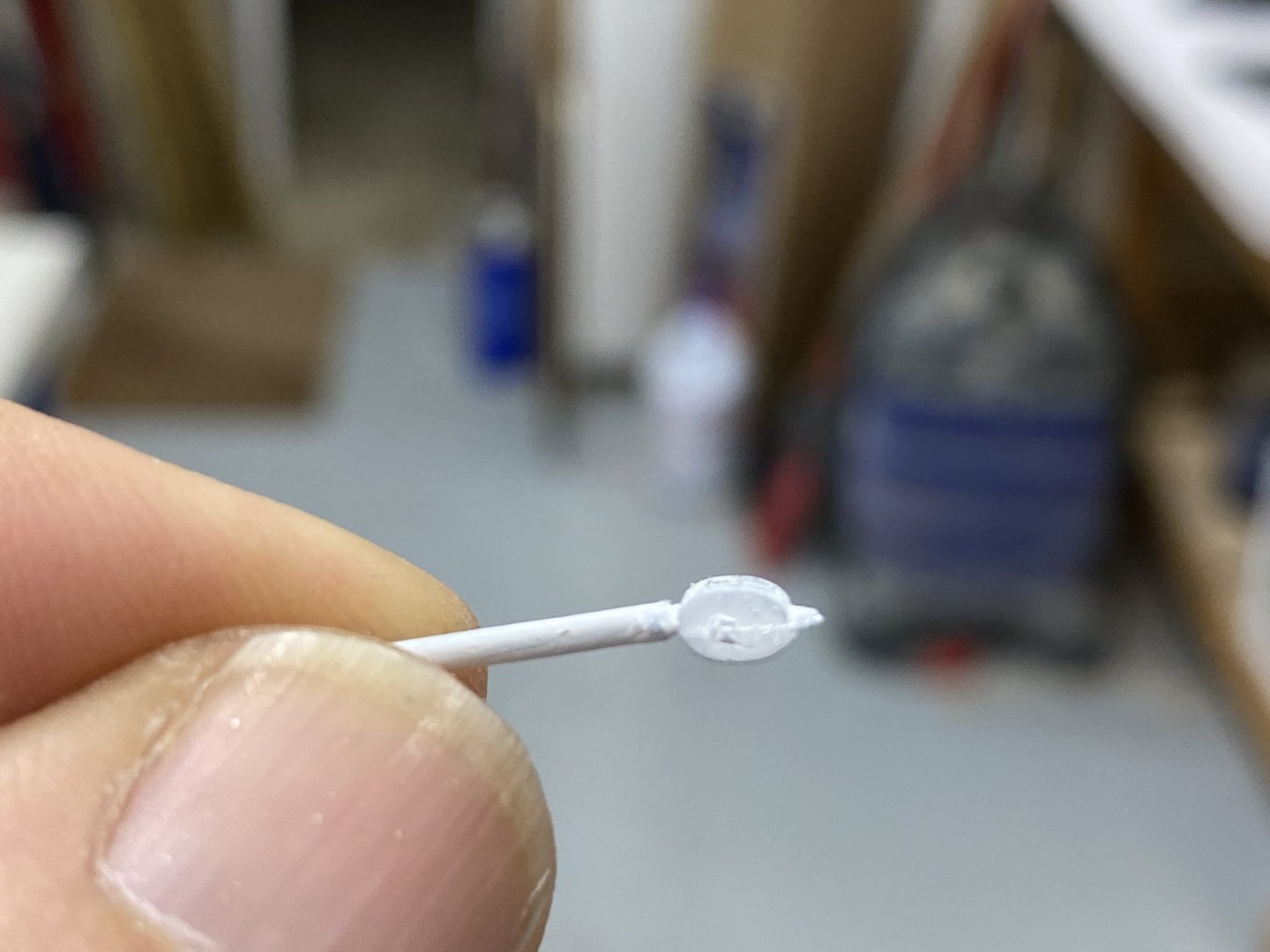
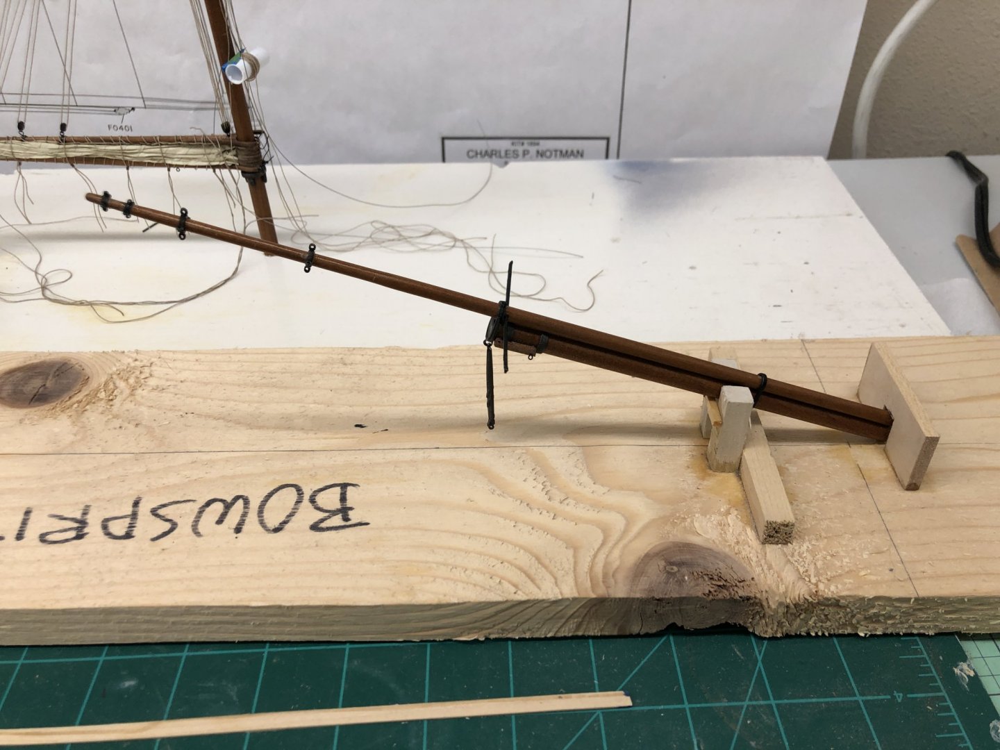
Now that the masts are done (more or less) it is time to work on the bowsprit. I initially tried to drill holes for the inner stays in the whisker pole but quickly realized that trying to drill a hole in a 1/32 round rod was not going to be easy - and getting four of them drilled without having even one get out of bounds was more than I was capable of. So I flattened the end and cut the groove per the instructions (and that was not all that easy) and will loop the inner stays around the pole as was done on the prototype. I had the basic pieces already shaped and finished so it was a relatively short process to do the assembly per the instructions. Speaking of which, they seem to imply that the dolphin striker is to be left attached to the eyebolt on the underside of the bowsprit cap but not glued in a particular position. In theory the dolphin striker is positioned by the stays that pass through/around it but this is the first kit where it has not been glued to the bowsprit cap. Speaking of the stays, I started working on the Britannia metal deadeyes supplied with the kit to try and get the groove around the outside cleaned up from the mould marks and extra material. After about a half dozen I gave up and orders some 3/32" wooden deadeyes from Model Expo. I have experience with these and will paint them flat black. I believe that a consistent groove is important on these since one end needs to be secured with a eyebolt in most of the places they are used. I have not tried this with the Britannia metal ones before and decided it was easier to switch than fight. Anyway here is the bowsprit waiting with the masts.
- 144 replies
-
- 3
-
-
- charles p notman
- finished
- (and 1 more)
-
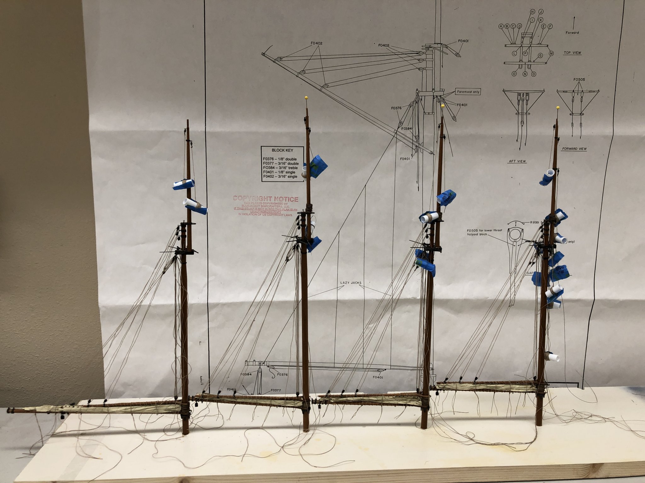
And then there were four! Mast assembly and initial rigging (peak halyard, throat halyard and topping lifts) is complete and the masts are "resting" in their temporary home until they are needed onboard. I also added the forward pin rails and drilled the holes for the belaying pins in the fly rail. I added the pins everywhere on the fly rail and where the belaying plan shows them in the forward pin rail. I am not sure what I am going to do with the pins that are not used. There are quite a few of them. I am not sure the kit has enough to put a pin in every hole and even if it did I am not sure that would look all that "authentic". I notice there are eyebolts at several points on the fly rail but nothing is shown using them. At the moment I am thinking about whether they are worth adding if they are unused. Here are the four masts and a shot of the forward pin rails and the belaying pins in the fly rail.

- 144 replies
-
- 3
-
-
- charles p notman
- finished
- (and 1 more)
-
Chris - I updated my profile to show the current build as the Charles P. Notman but it does not seem to be reflected in is the info that follows my name when I submit a post.
Have I done something incorrect?
GLH
-
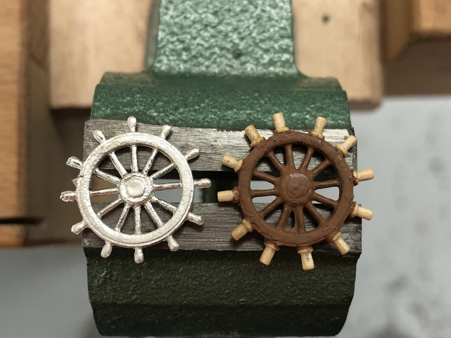
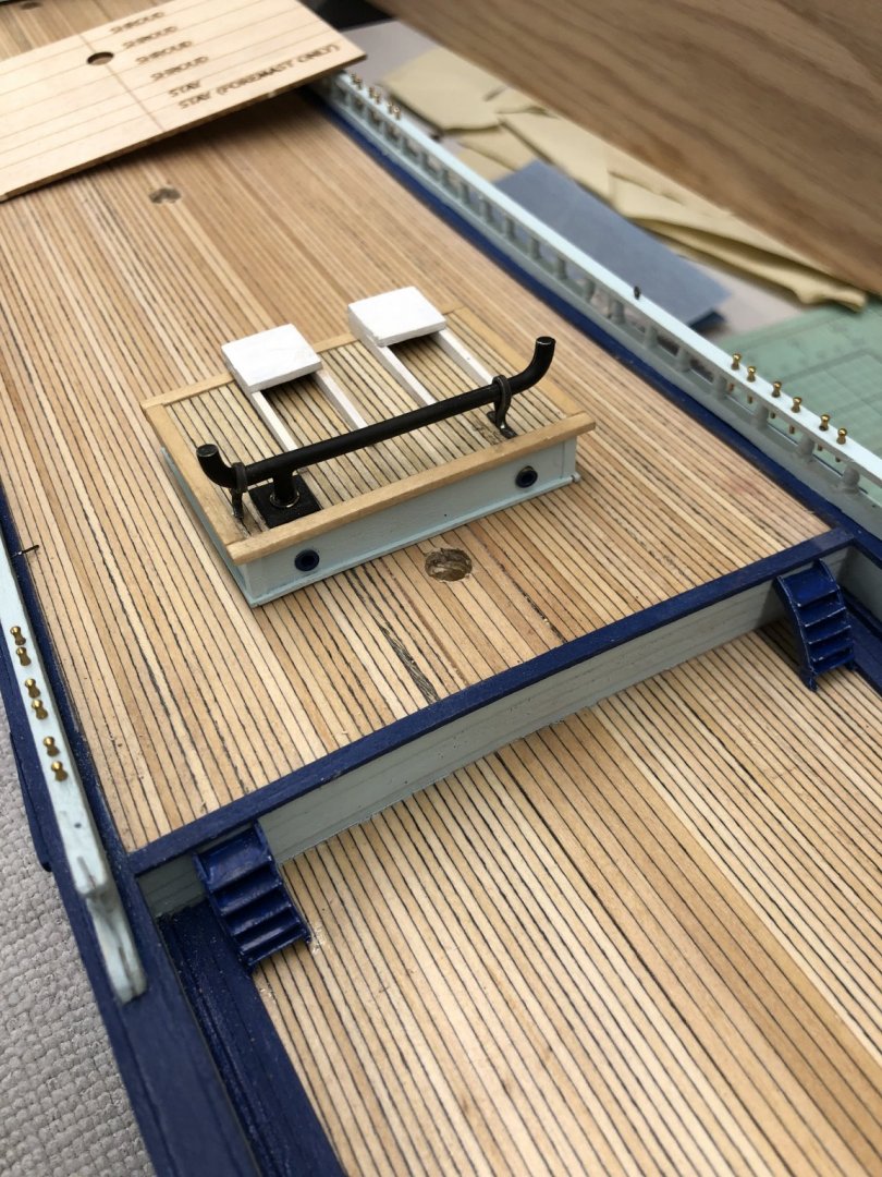
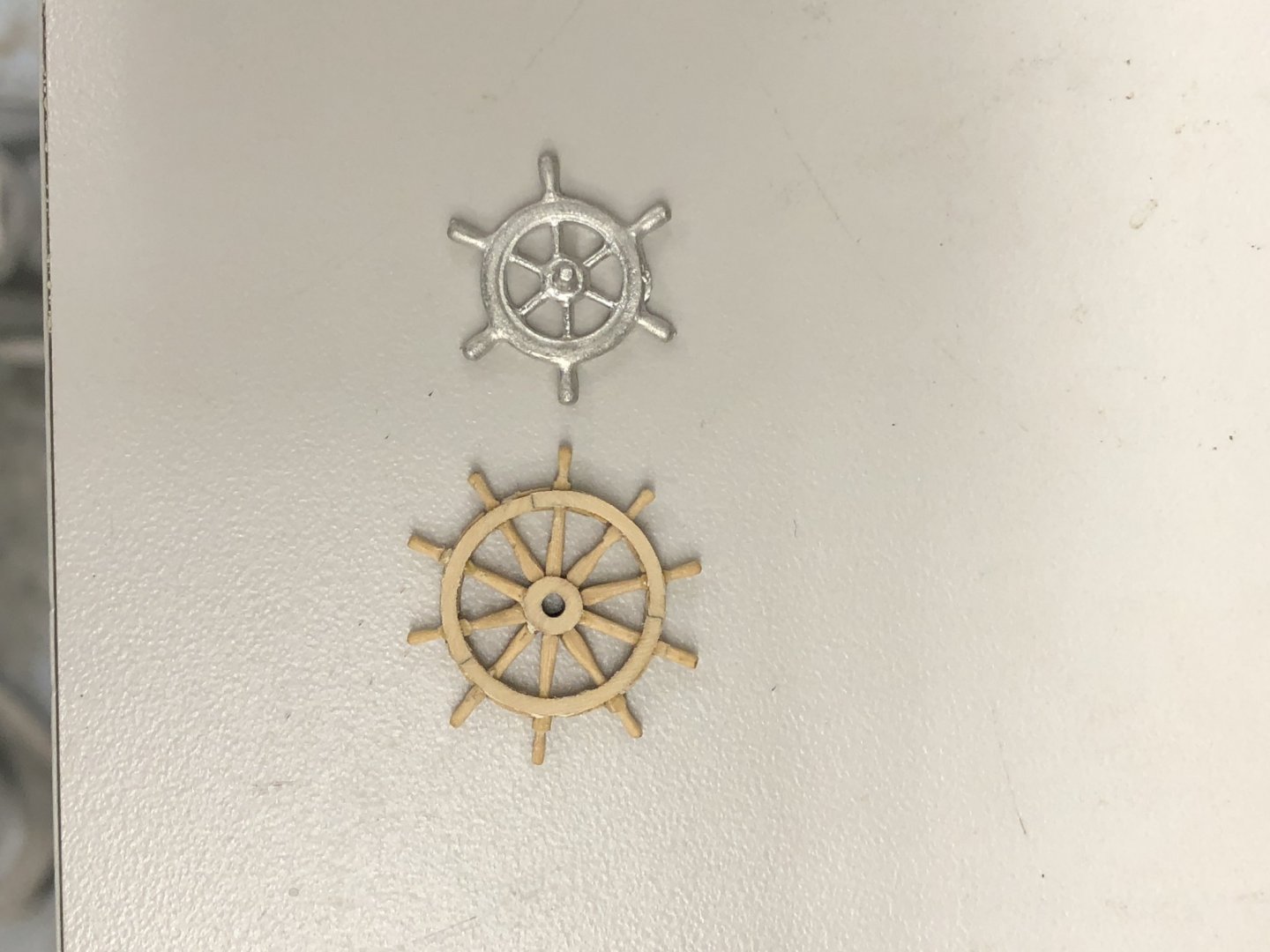
While looking for something else I ran across a Syren kit for a ship's wheel. The label said it was 15/16" diameter. I looked at the parts list and the ship's wheel (Britannia metal) included is 3/4" diameter so I thought I would use the (much nicer IMHO) wooden wheel. I spent most of yesterday putting the wheel together. It is quite a task with a bunch of small delicate parts that need to have the laser burn removed. To its credit the kit includes plenty of spare pieces to accommodate the to be expected problems (including dropping a small piece and being unable to locate it on the floor and breakage. Here are the two wheels side by side - wooden one is bare wood - I will stain it cherry if I use it. After all that work I am not sure the wooden one will really work. At full size the wooden wheel would be 7'6" in diameter compared to the Britannia one which is 6'. At the very least I will have to modify the wheel box to provide the additional clearance so the wooden wheel will clear the deck.' We will see as I get closer to having to make a decision.
- 144 replies
-
- 2
-
-
- charles p notman
- finished
- (and 1 more)
-
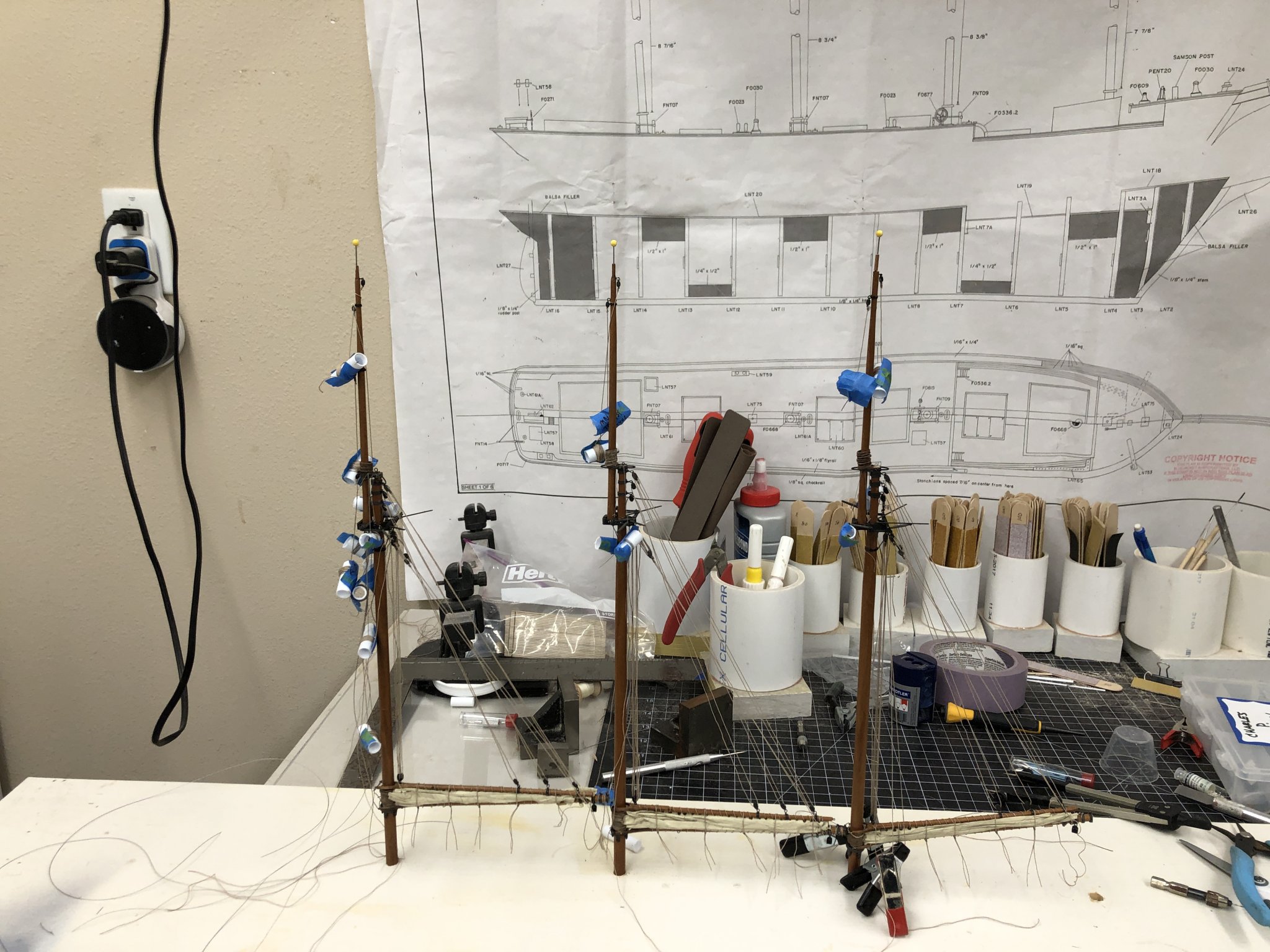
And then there were three! Last night while fumbling around in one of the cabinets above my work table I found a "Ratliner" which I believe I got from Model Expo some time ago. It purports to allow assembly of an entire shroud/ratline set (for one side of a mast) off board. I never tried to use it but was intrigued enough (after rereading the included instructions) to order one for the closest to the Notman scale (they come in 1/48, 1/64 and 1/72-1/90 sizes). I plan to give it a try on the Spanker since you have to have the bare lower mast head available - no topmast to be able to slip the loops at the shroud tops over the lower mast head.

- 144 replies
-
- 5
-
-
- charles p notman
- finished
- (and 1 more)
-
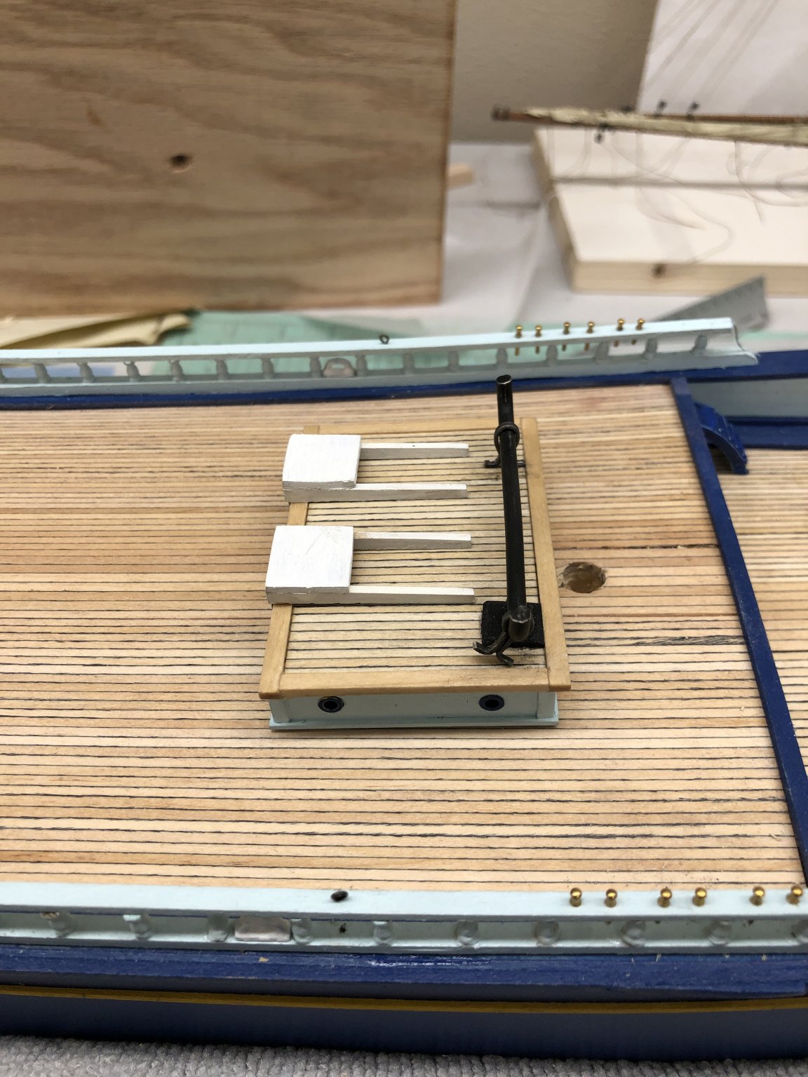
While waiting for glue to dry on line seizings I glued in the ladders (no stairs on ships I am told) to the main deck.
- 144 replies
-
- 3
-
-
- charles p notman
- finished
- (and 1 more)
-
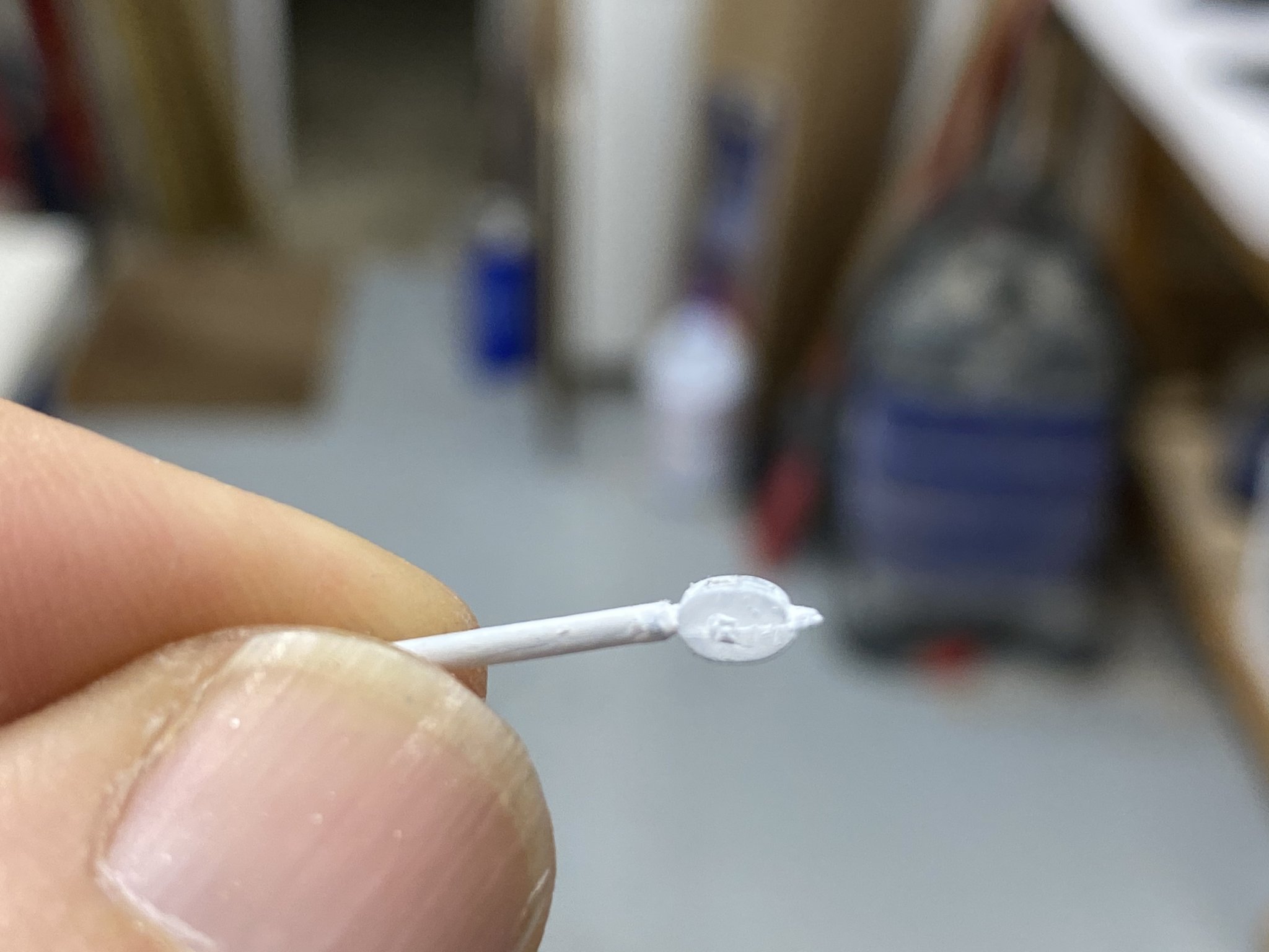
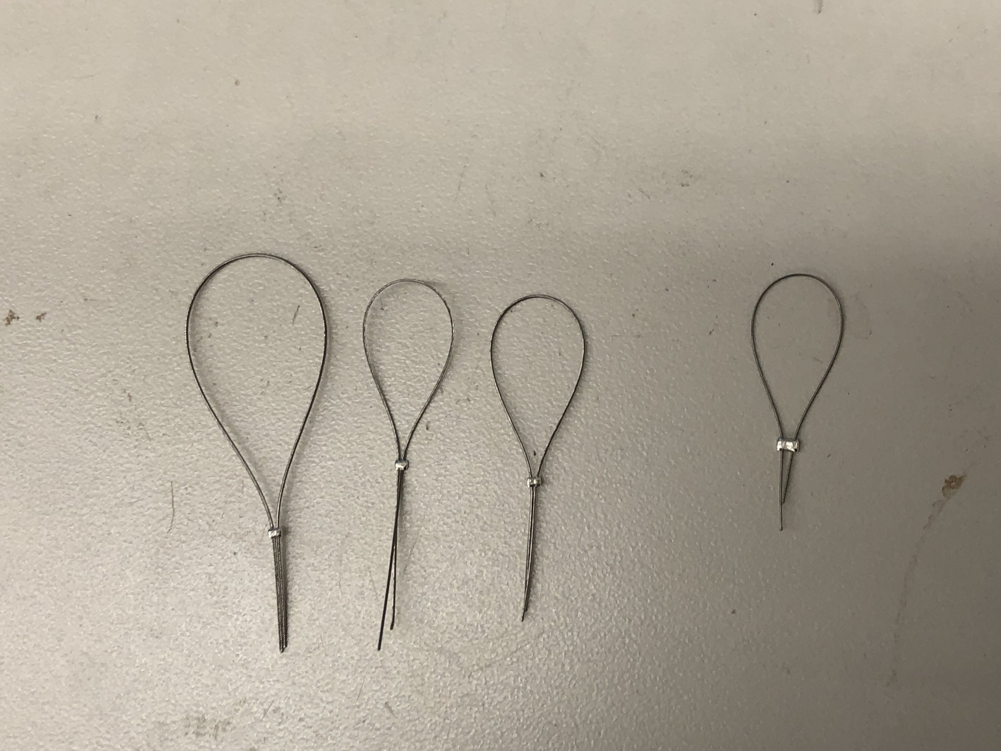
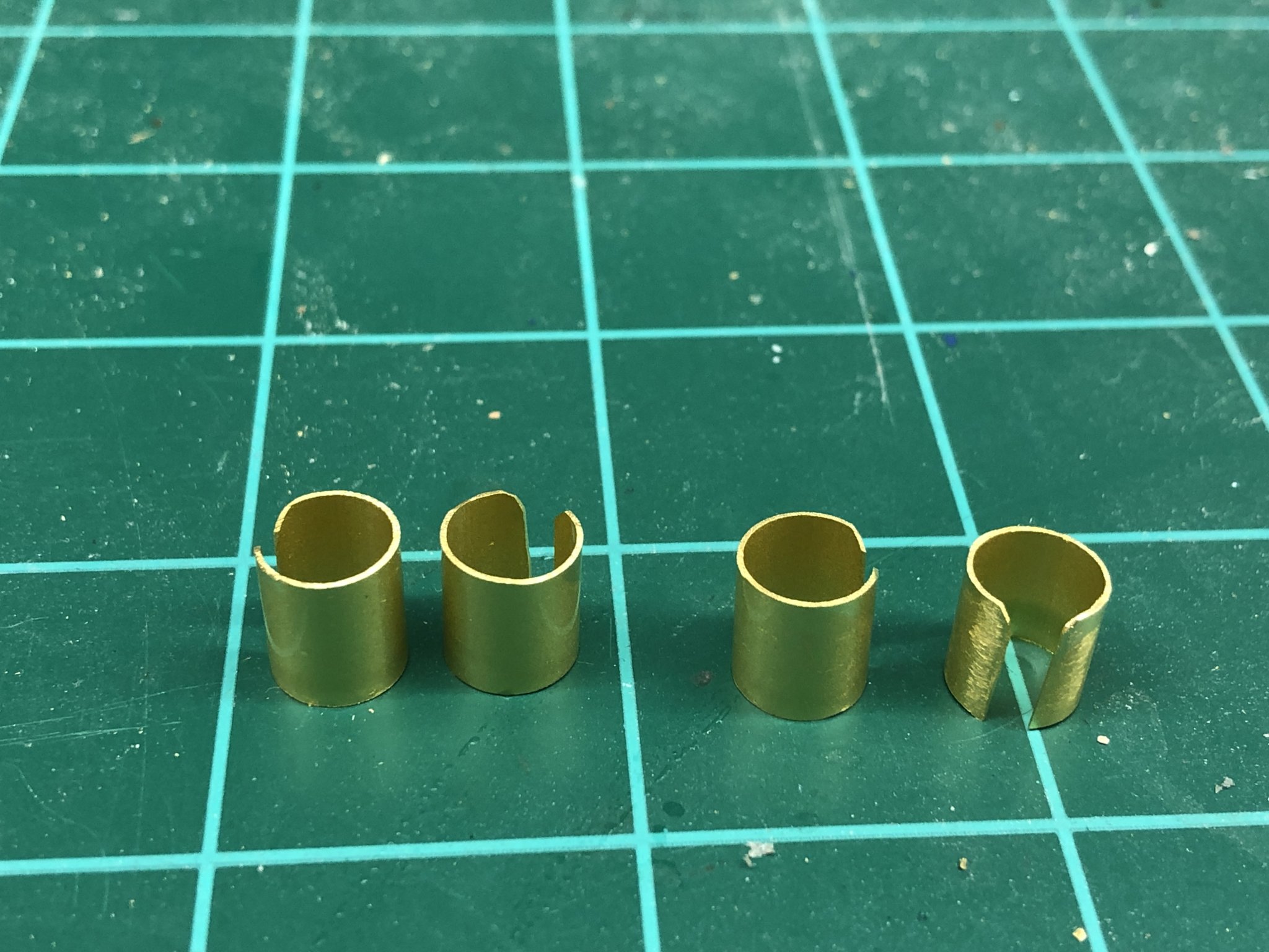
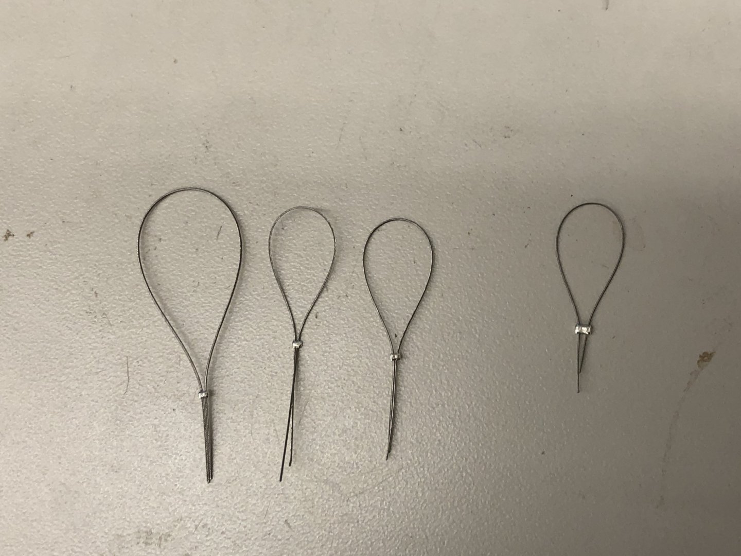
The size 0 crip "beads" arrived yesterday. Based on what I can see online, the crip tubes (cylinders) do not come small that size 1. Only the "crip beads" come in size 0 (although the data seems to indicate that they are the same size as the size 1 tubes - not clear what dimension is being quoted, at least to me). So I used the size 0 beads to join the .010, .012 and .015 Beadalon silver line and the size 1 tube on the .010. You can see the difference below. So I will use the size 0 "beads" for joining the Beadolon wire that simulates the galvanized wire used for the standing rigging.
- 144 replies
-
- 2
-
-
- charles p notman
- finished
- (and 1 more)
-
Main mast is now as complete as the Fore and both are installed in the temporary "holder". I attempted to rig the boom topping lifts with the lazy jacks already attached to the topping lift lines but abandoned that approach as it was too hard to accurately place the lazy jack lines and keep the lines separated while installing. My approach at this point if to rig the topping lifts without the lazy jacks and wait until the masts are installed on the hull to rig the lazy jacks. I believe that you need the peak and throat halyards and sheet lines tensioned to their final position to accurately position the lazy jacks. I am using .012 Syren tan line for the topping lifts and have dyed some of the Bluejacket white .005 line to match (more or less) to use for the lazy jacks and have demonstrated that the .005 can be successfully inserted (with a sewing needle) into the .012 so that is how I plan to attach the lazy jacks to the topping lifts.
- 144 replies
-
- 4
-
-
- charles p notman
- finished
- (and 1 more)
-
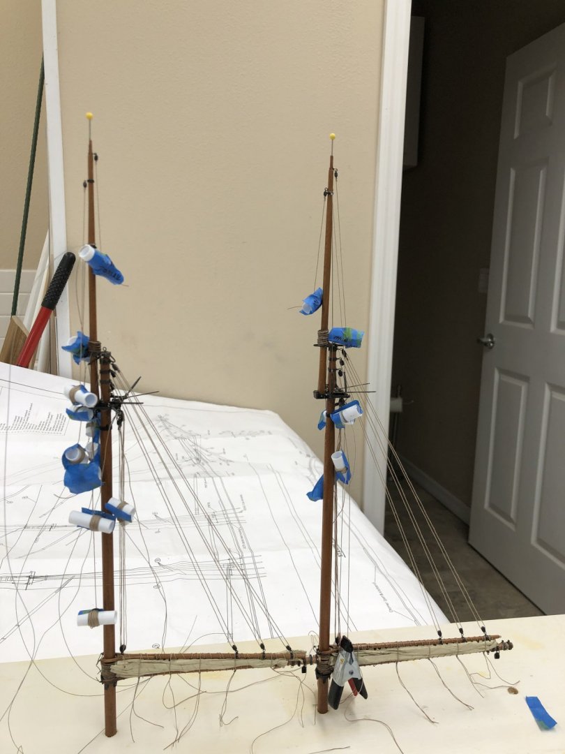
I have the Foremast about as complete as I can get it without actually installing it onboard. I have all the halyards (a total of eight - Jib Staysail, Outer Jib, Flying Jib, Jib, Fore Staysail, Peak, Throat and Fore Topsail), the cap and fool stays, topping lifts for the Jib and Fore Staysail and Fore sail (port and starboard) booms. I am waiting for some size zero crimp tubes for the Beadalon wire before rigging the topmast shrouds and the rest of the stays that use the .010 size wire. The cap and fool stays use .012 and the size 1 tubes seem to be okay for that size. I may redo the cap and fool stays if the size 0 tubes really looks better. I added the chafing plate and the boom rest and the boom and gaff with the furled sail - it has the be done before the boom rest is added. I fabbed some gaskets to hold the boom/gaff in place (instead of the zip ties) and rigged the peak and throat halyards since they do not need any other parts and it reduces the clutter of lines by two. I am thinking of working the boom topping lifts next since that will clear all the lines off the after side of the lower Foremast. My plan is to get all four masts in this state (although the others have significantly fewer halyards and stay to deal with) and stored in a temporary fixture while I get the deck furniture and chainplates done. Then the fun really starts.
- 144 replies
-
- 4
-
-
- charles p notman
- finished
- (and 1 more)
-
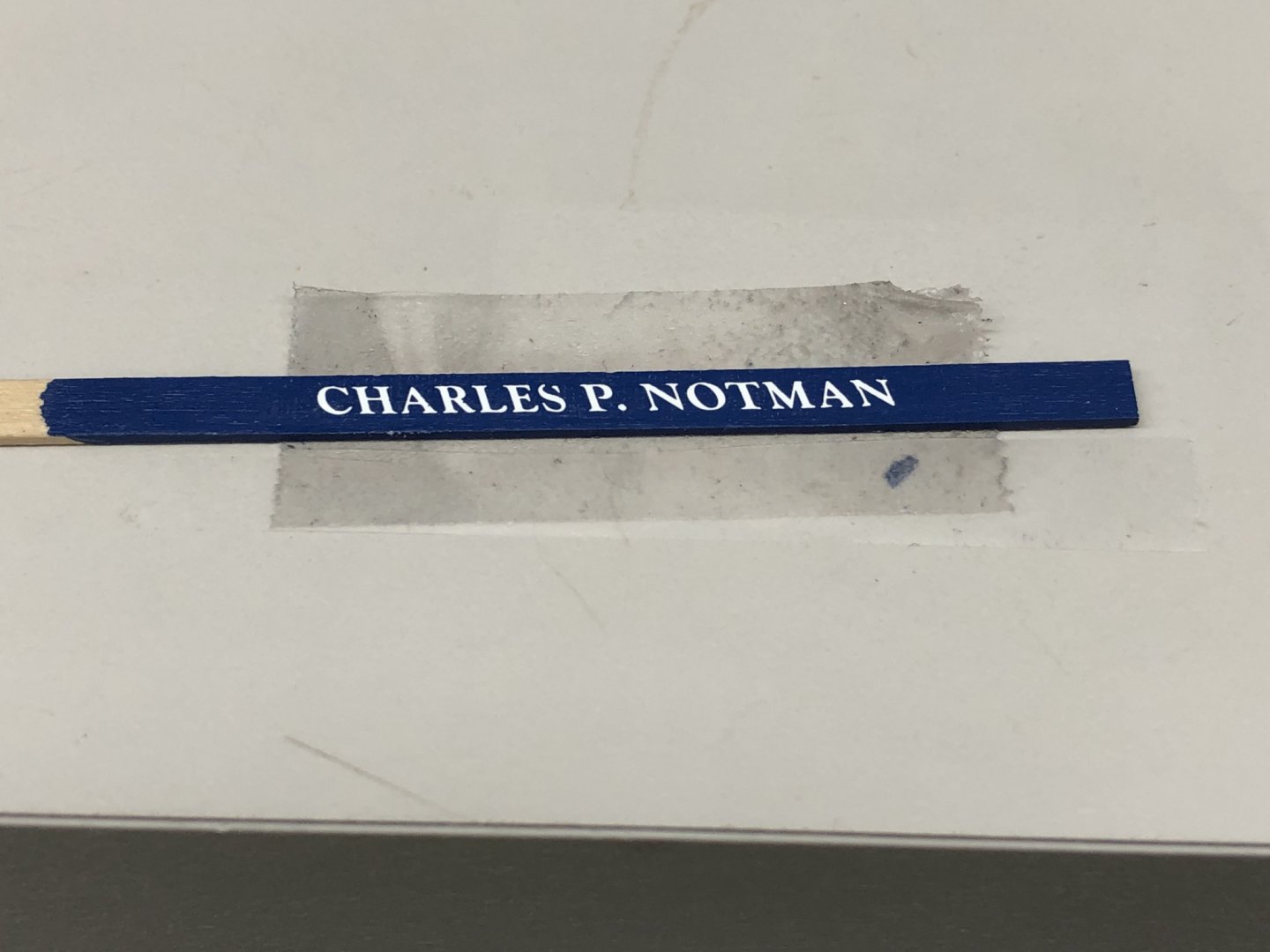
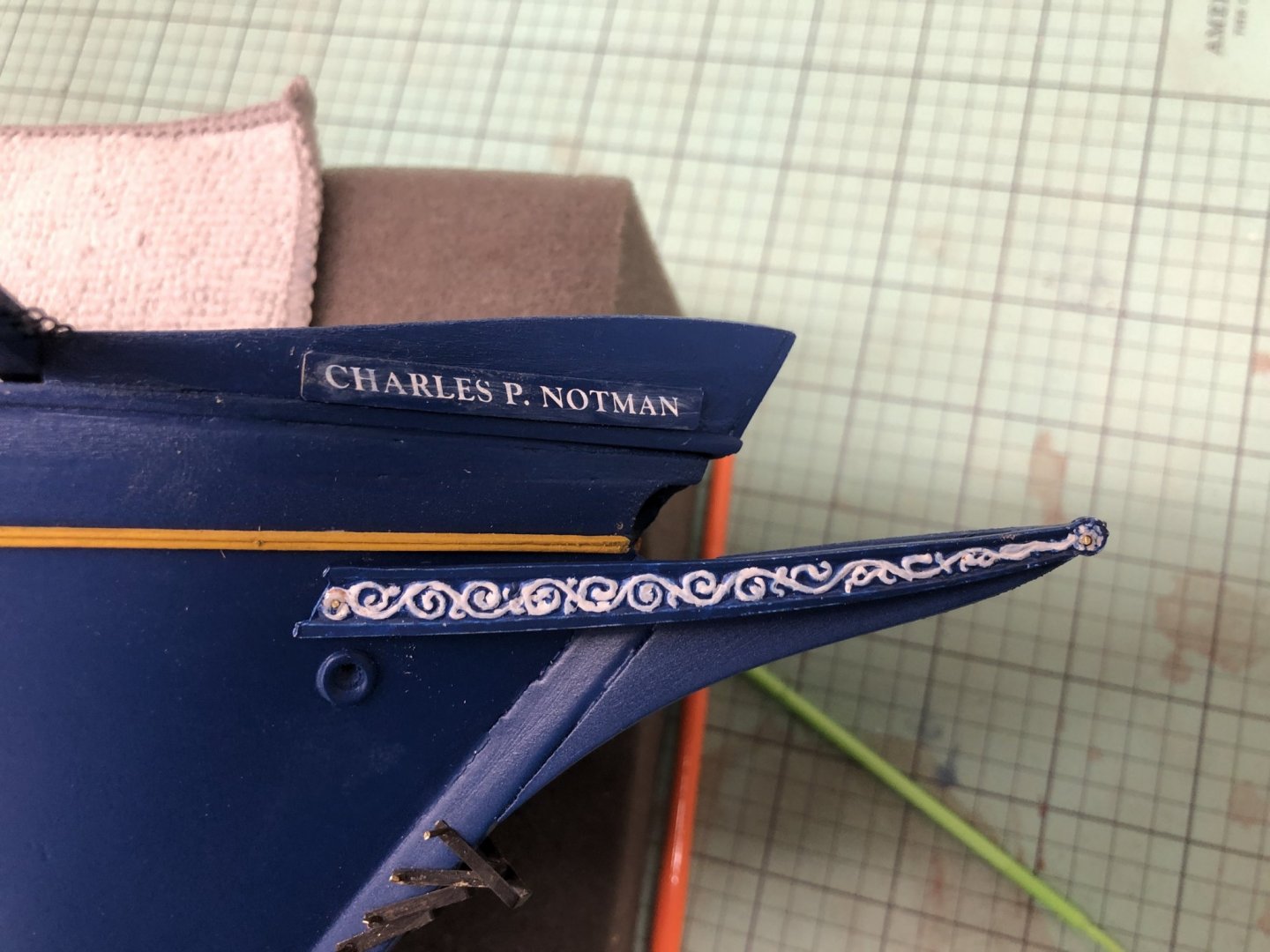
More odds and ends this morning. I got the name board for the stbd side finished. I used double sided tape to hold the board down then used scotch tape top hold the transfer sheet in place. I used the side of a sanding stick (aka tongue depressor) to rub the transfer on, removed (carefully) the scotch tape and then rubbed again directly on the transfer sheet. I came out pretty well - I only missed a small part of the "s". Here it is as it looked after the transfer and installed on the hull. I still have to clean up the trail board where the pins are. I also cut and cleaned the brass tubing that will be the mast chafing plates. I used Jax "Instant brass and Copper Cleaner". It really isn't "instant". It took five minutes in the ultrasonic cleaner while immersed in the cleaner to get them looking like this. Almost a shame to paint them but they won't stay looking like this for long in the Florida heat and humidity.

- 144 replies
-
- 4
-
-
- charles p notman
- finished
- (and 1 more)
-
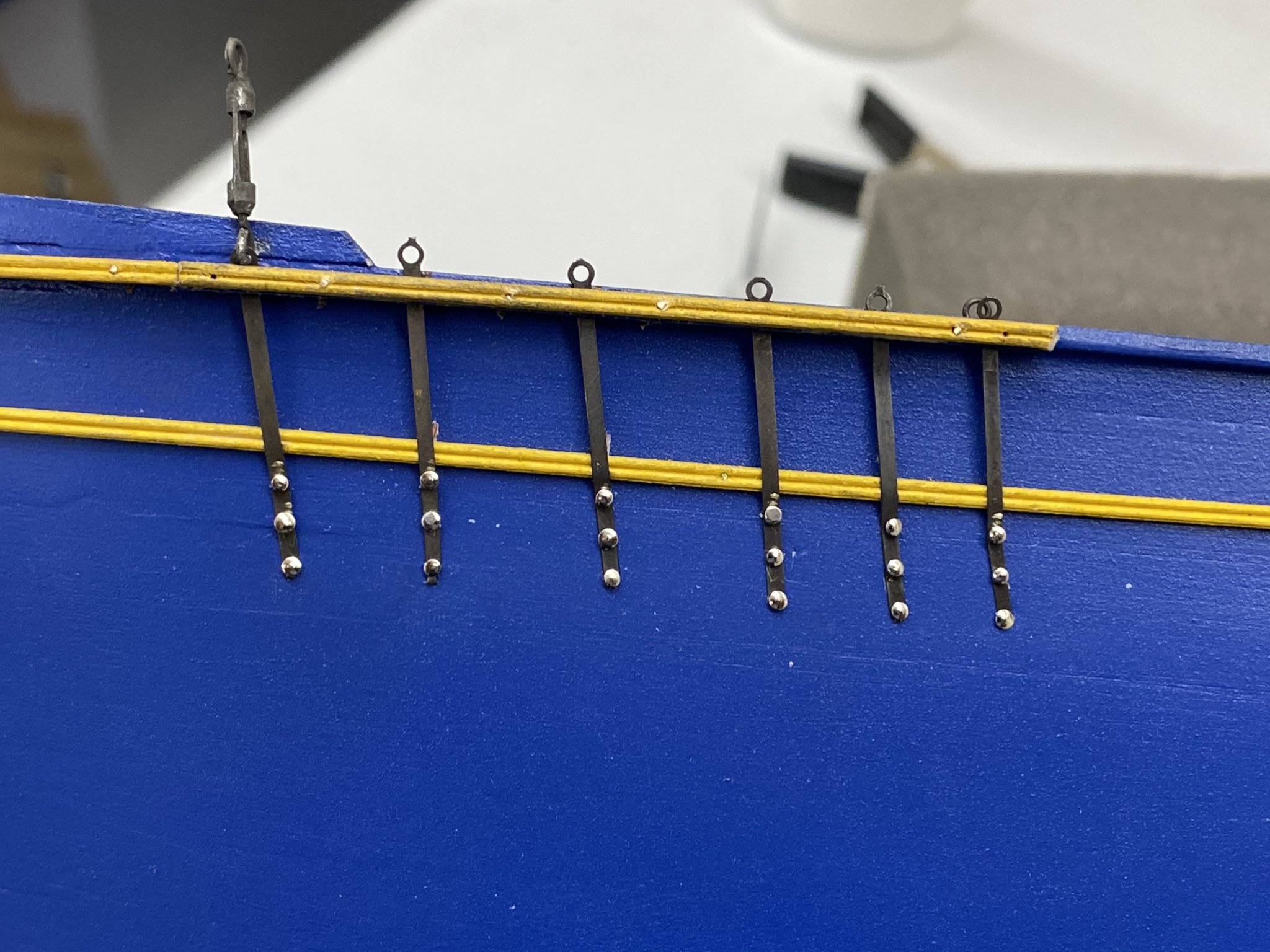
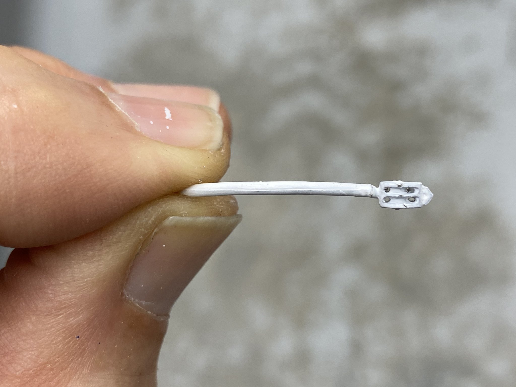
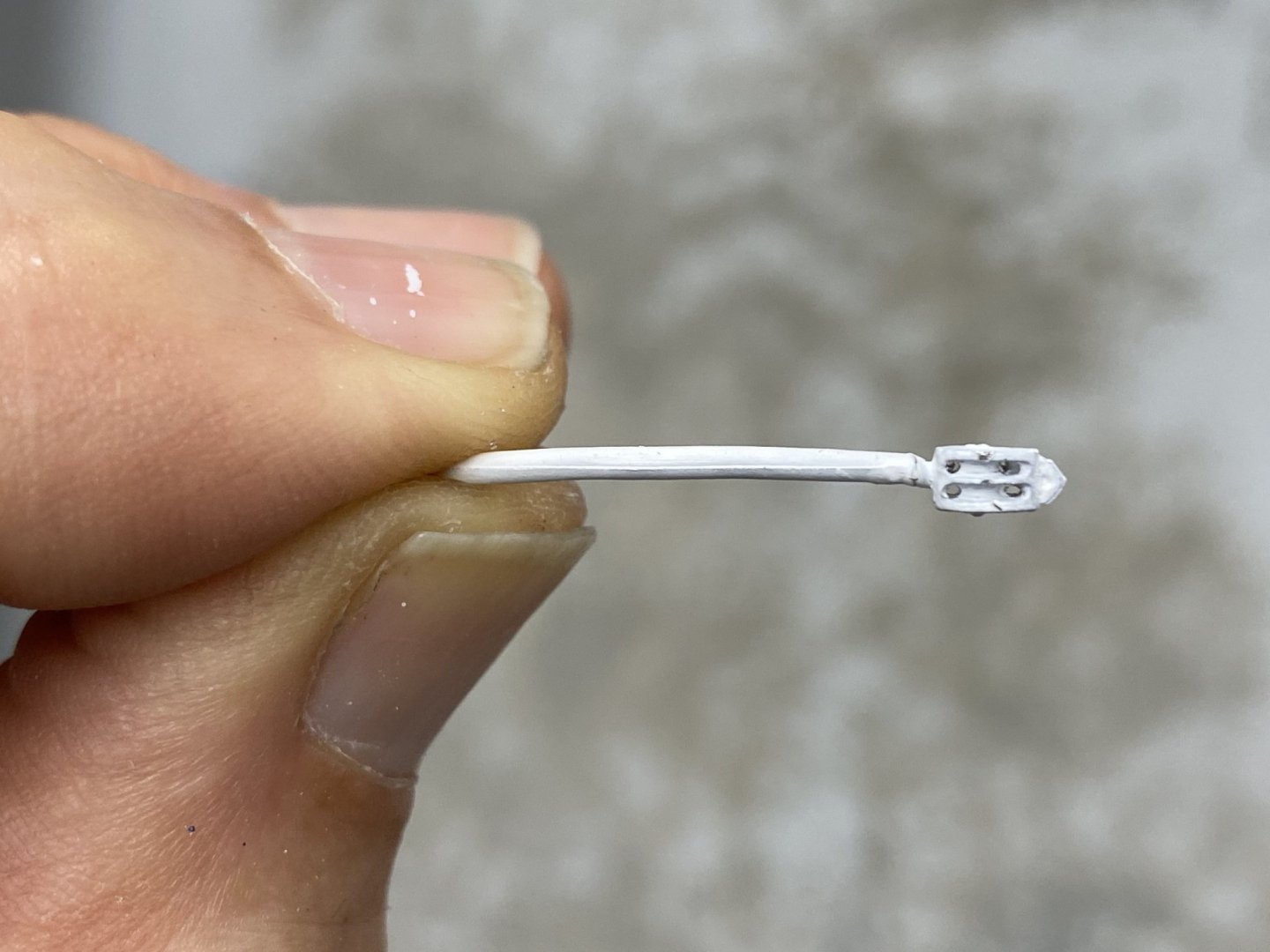
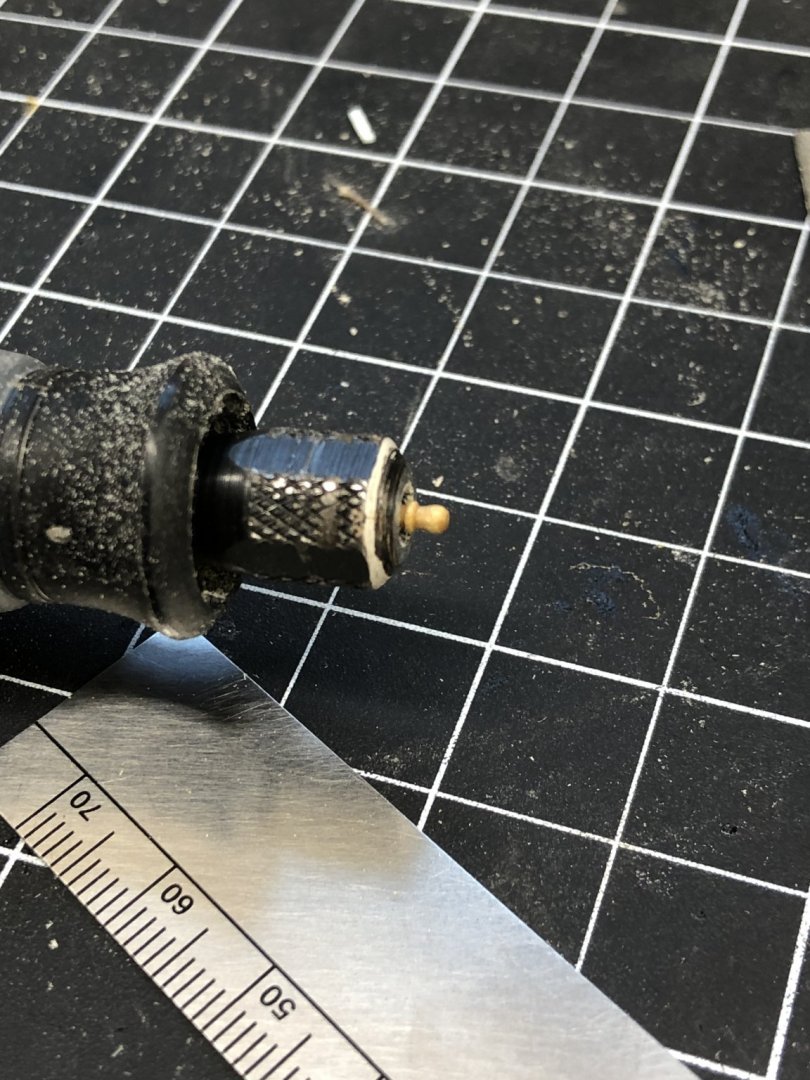
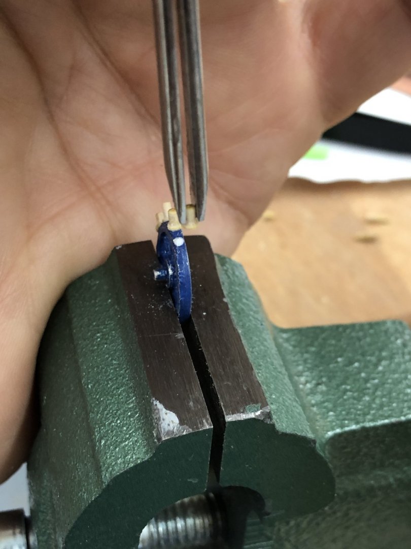
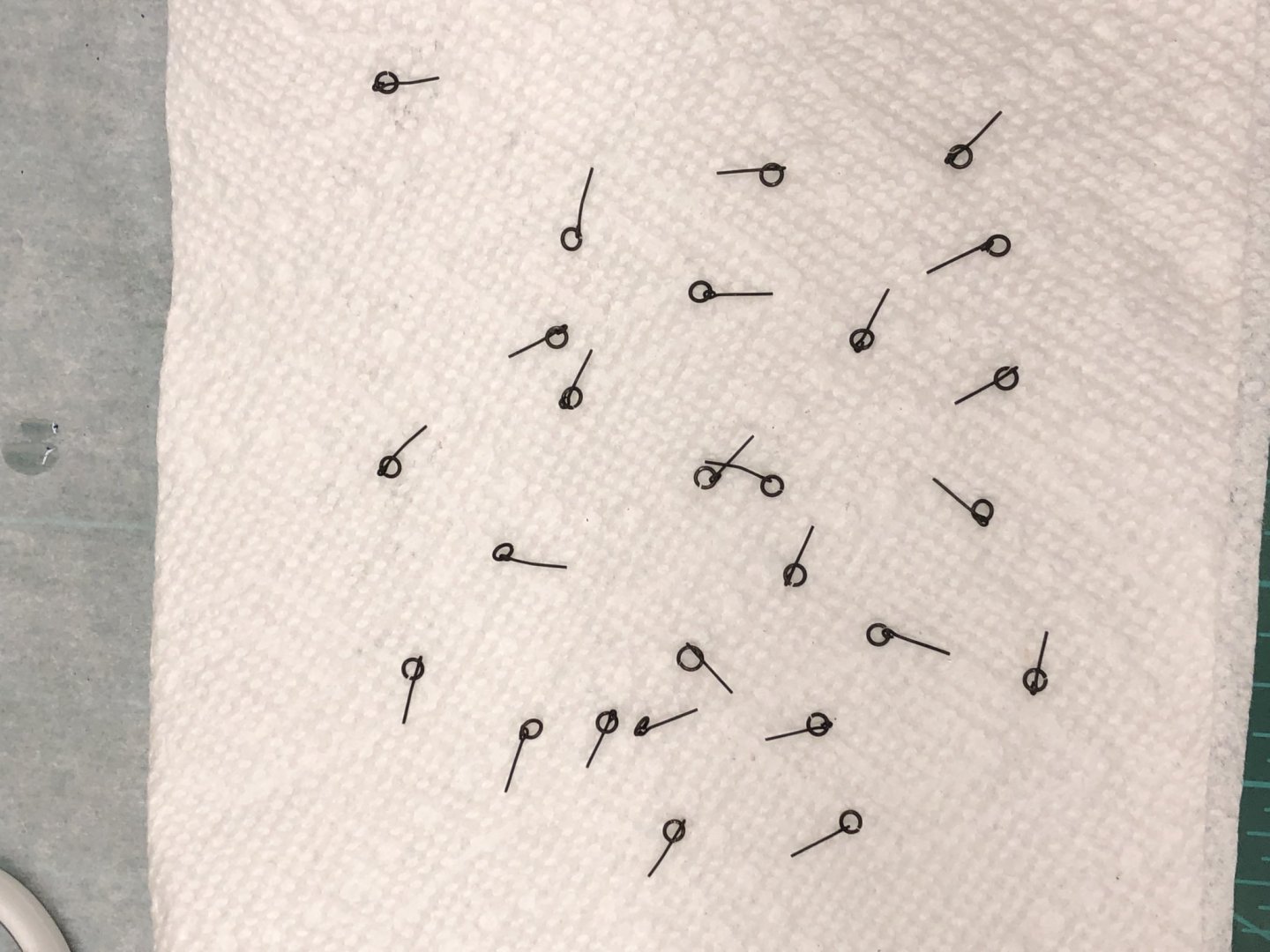
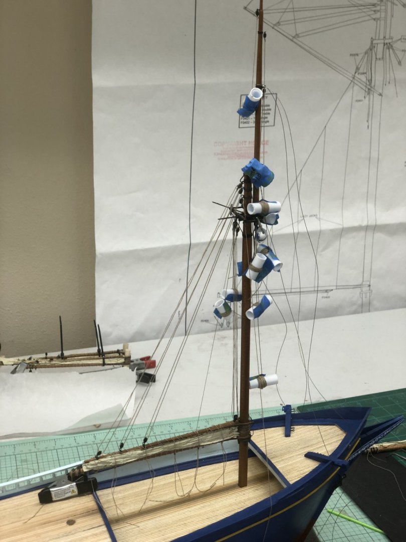
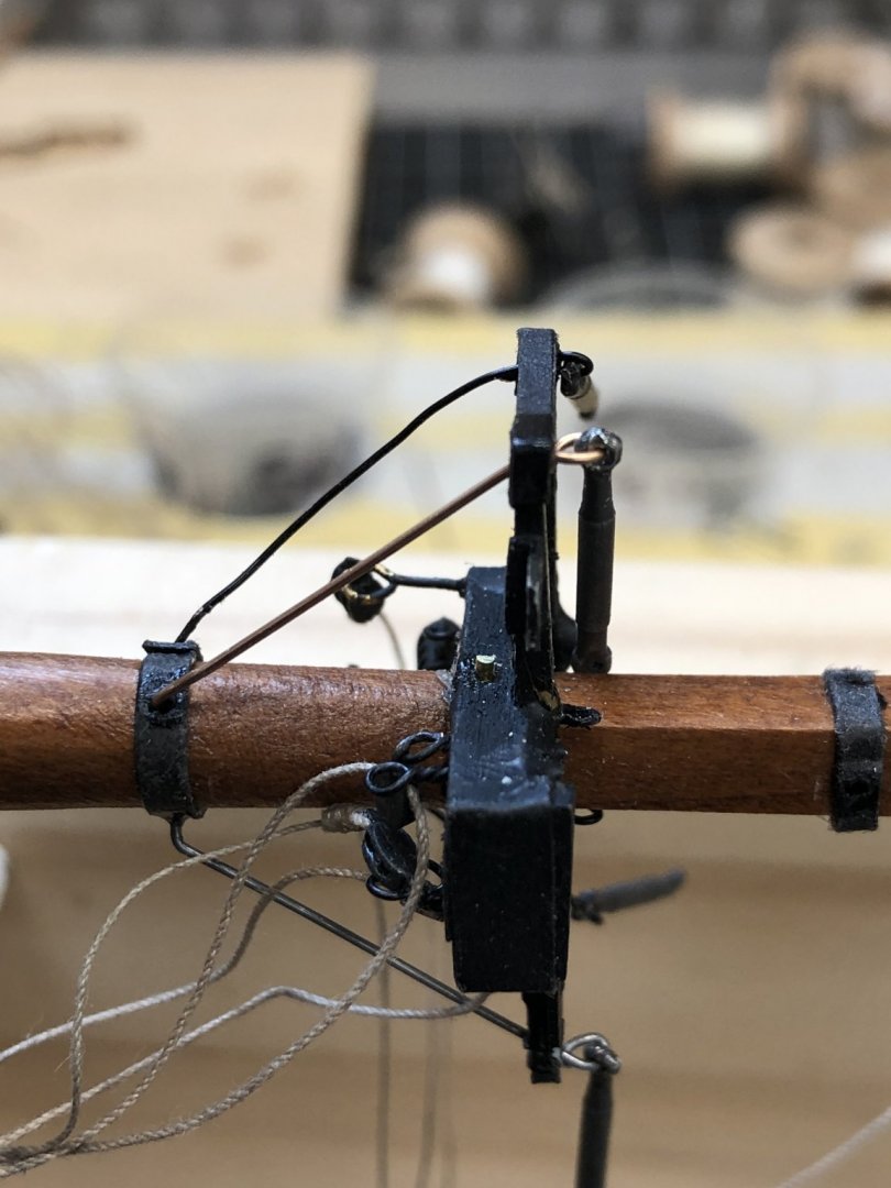
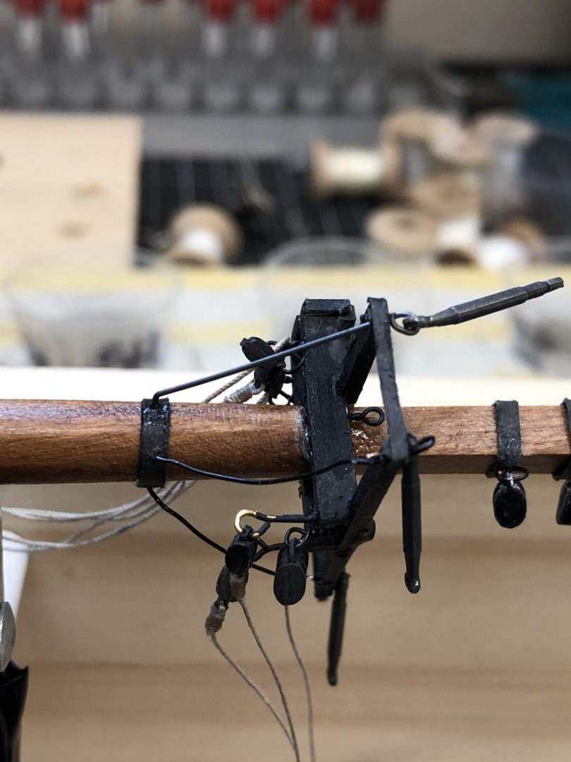
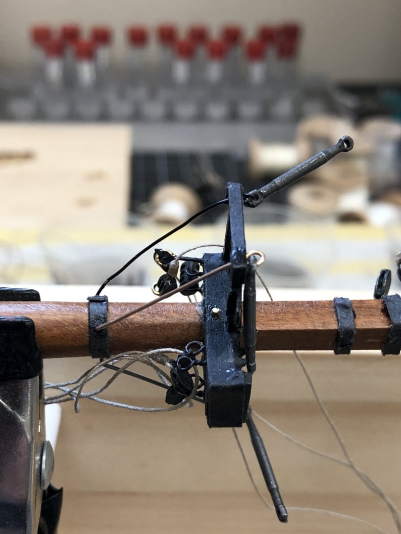
With the fore, main, mizzen and spanker sails mounted on the spars and furled (more or less) it is back to working on the masts. I have been installing the futtock shrouds. The first issue is with the instructions which direct forming eyes in the futtock shrouds and then gluing them into the cross trees and the futtock shroud band on the mast. Later a turnbuckle will have to be attached to the eye in the futtock shroud. Would be easier to form the eye with the turnbuckle already included rather than have to come back later and try and do it. That is what I did. My first attempt used 26 gauge copper wire that is painted black as it comes on the roll (from Artistic Wire). The problem is that it is hard to keep the wire straight. For this material I drilled out the hole in the cross tree to #68 and doubled the wire around the hole in the turnbuckle and down through the now larger hole in the cross tree. Worked "okay" as shown below (the far shroud - more on the closer one below). When that process did not seem to be acceptable I thought about using .020" music wire (which I have in "stock"). Music wire has the opposite problem from the black painted copper - it is very difficult to bend. I had to hold one end in a vise and grab the other in pliers to pull a small eye (with the turnbuckle inside). I used a Dremel cutting wheel to trim the excess wire at the eye. Measuring to get the correct length to hit the futtock mast band was another issue but after several false starts I finally got one installed. Here is what that one looks like - much better and I could probably get away with leaving it unpainted - at least for awhile (everything iron rusts here in Florida, even if in the a/c). After several unsuccessful attempts at doing a second shroud using music wire I thought I would try something else. I have .020 phosphor/bronze wire (I got mine from the Tichy Train Group) which is not nearly as stiff as the music wire but better than the 26 gauge by a good bit. It obviously will have to be painted but I am willing to do that to get a better looking shroud without the extra effort I experienced trying to use music wire. Here is one of the shrouds using the phosphor/bronze wire - before painting.
- 144 replies
-
- 4
-
-
- charles p notman
- finished
- (and 1 more)