MORE HANDBOOKS ARE ON THEIR WAY! We will let you know when they get here.
×


cdrusn89
-
Posts
1,915 -
Joined
-
Last visited
Content Type
Profiles
Forums
Gallery
Events
Everything posted by cdrusn89
-
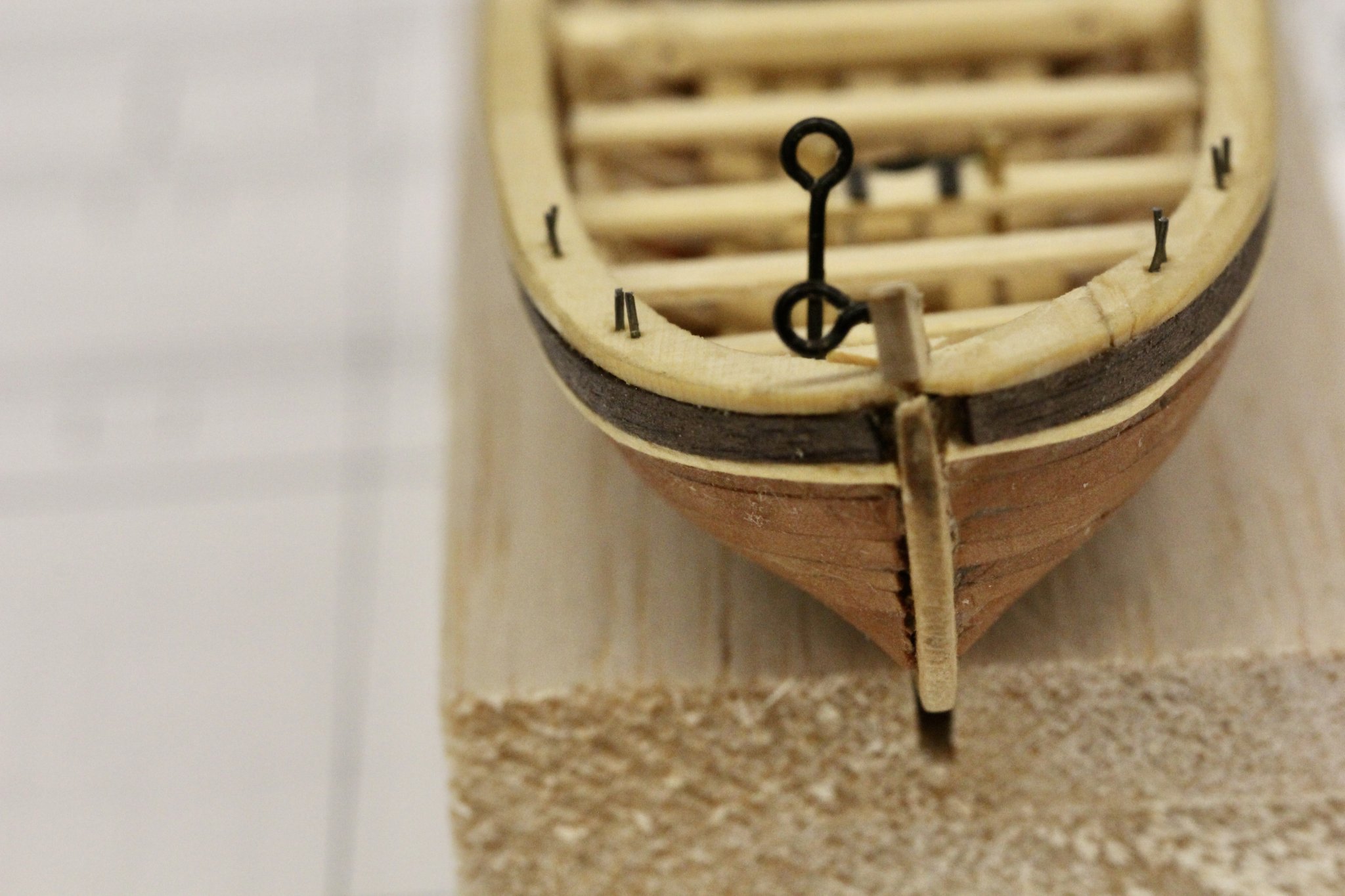
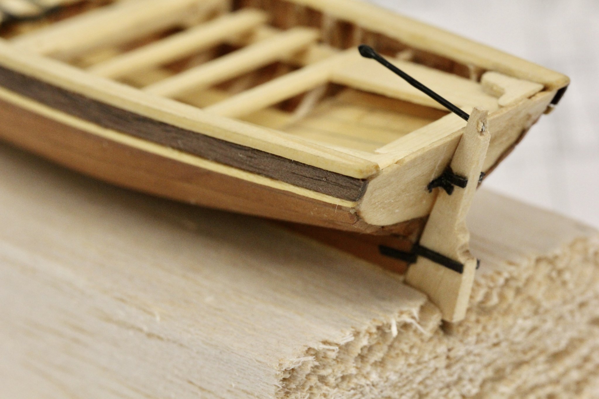
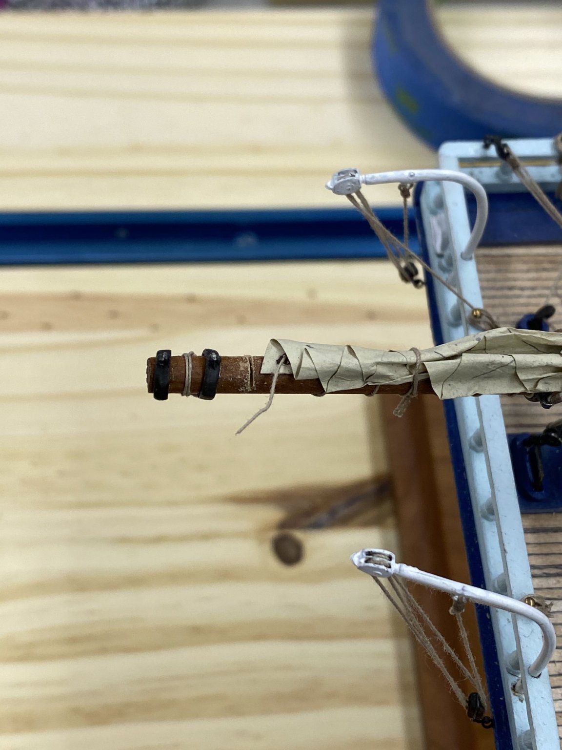
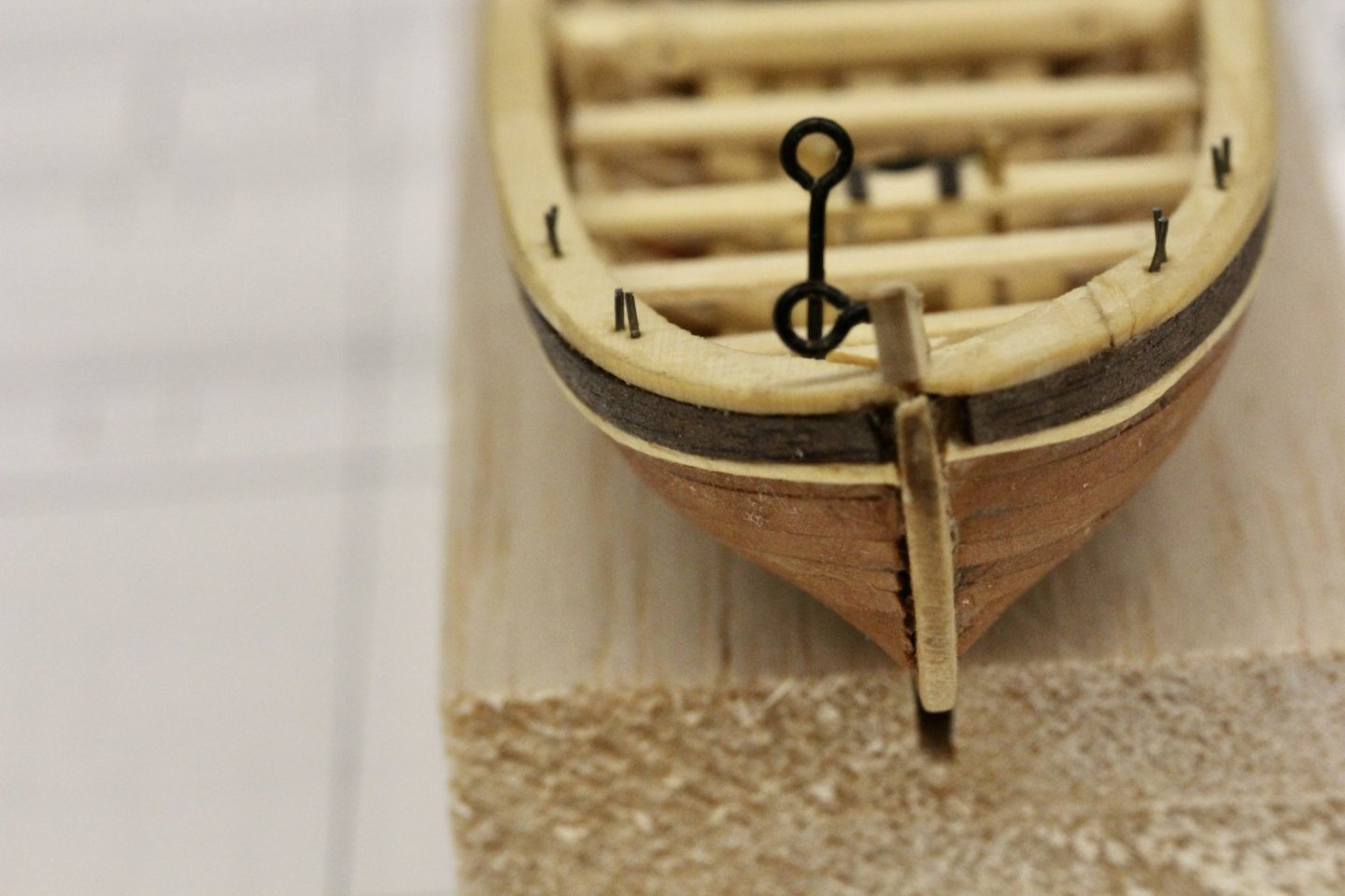
 The Longboat is done (except for some more oar locks and a coat of clear flat on the topsides). I "cheated" and used some large eyebolts for the bowsprit holders instead of brass strips. It was a bunch easier (just blacken and cut to length). For the "bulb" on the end of the tiller I dipped the .025" piano wire in Mr. Finishing Surfacer 1500 and then hung the wire vertically. The Mr. Finishing Surfacer 1500 will drip off the end of the wire until the last drop is not big enough to fall off. When it dries you have the "bulb" and the wire is black to boot. Here is the long boat: Now I have to finish the tackle for the guns and then the real Confederacy can begin in earnest.
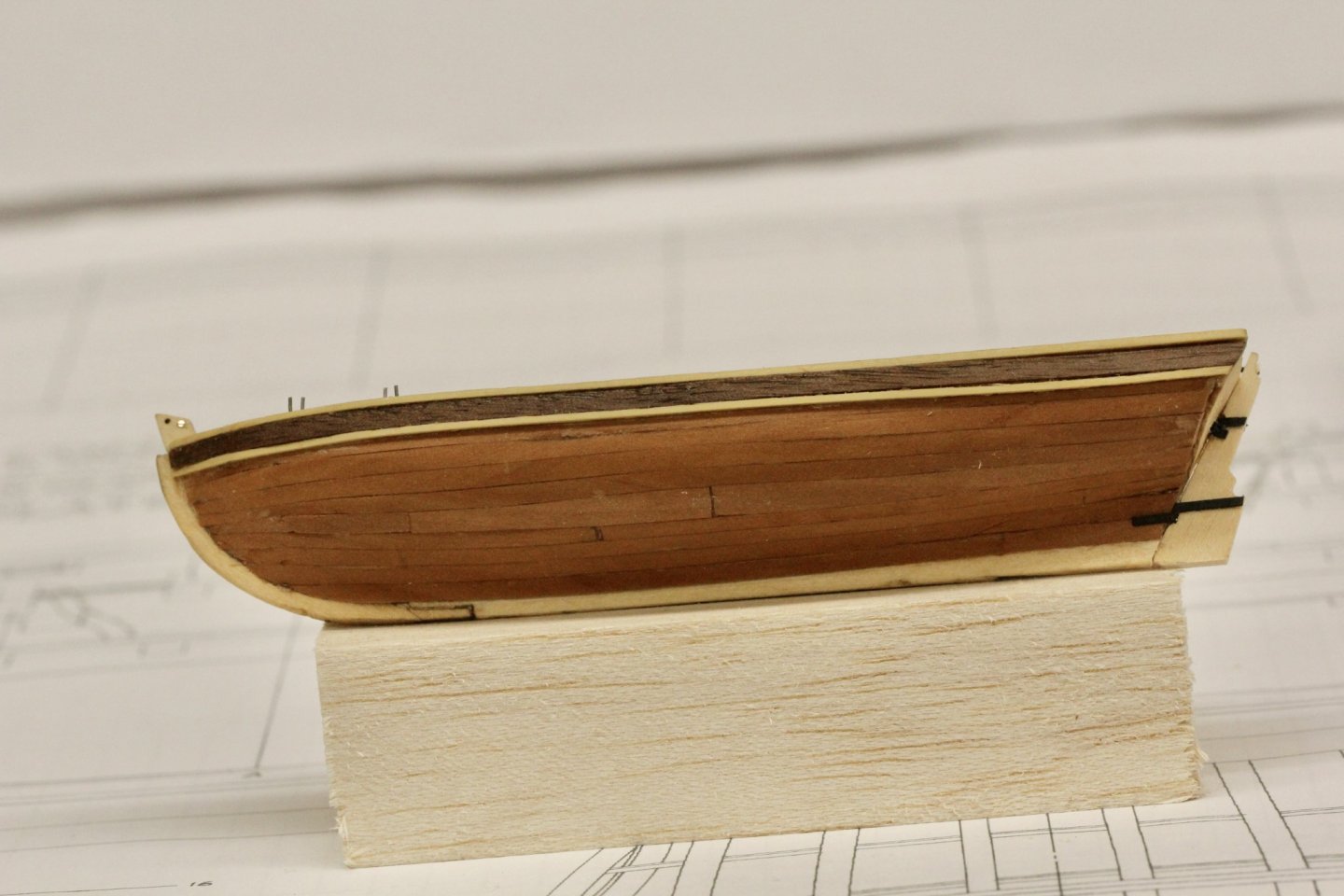


- 370 replies
-
- 2
-

-
- Model Shipways
- Confederacy
- (and 1 more)
-
The longboat is moving along (slowly) but the "real" ship is moving along. I created a template from a file folder for the bearding line at the stern (since the laser cutter only works on one side) and then glued the rabbit strip onto the bulkhead former.

- 370 replies
-
- 2
-
-
- Model Shipways
- Confederacy
- (and 1 more)
-
Now the the bulkhead former is dry here it is on the build board (upside down) with the wet rabbit strip in place to dry before being attached.place
- 370 replies
-
- 2
-
-
- Model Shipways
- Confederacy
- (and 1 more)
-
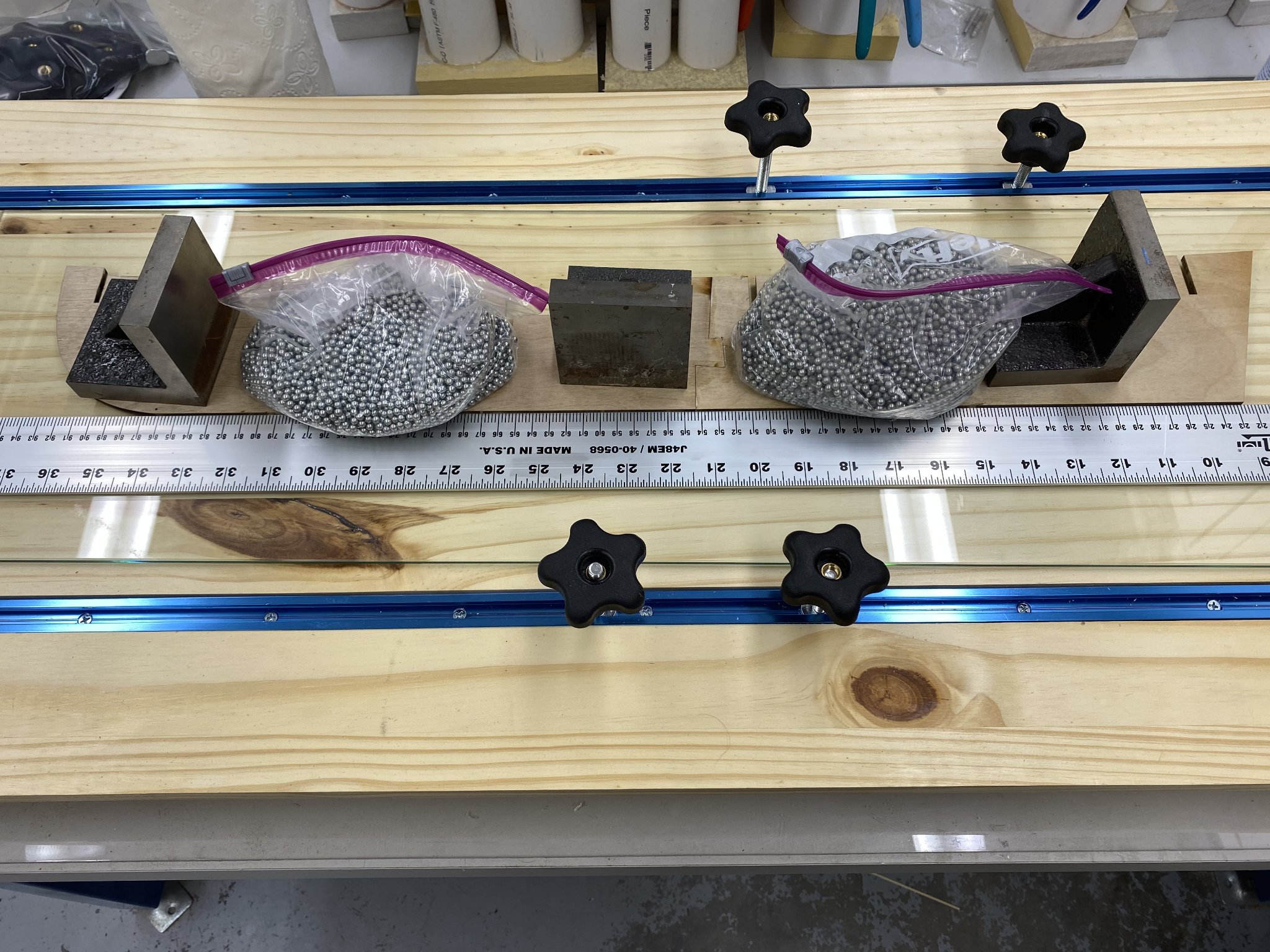
With one of the boats done I could not resist starting on the "real" Confederacy. I used one of the glass shelves I had to remove from my new display cabinets so the ship models would fit to support getting the bulkhead former together in a straight line. Here is the assembly weighted down while the glue dries (overnight).

- 370 replies
-
- 2
-
-
- Model Shipways
- Confederacy
- (and 1 more)
-
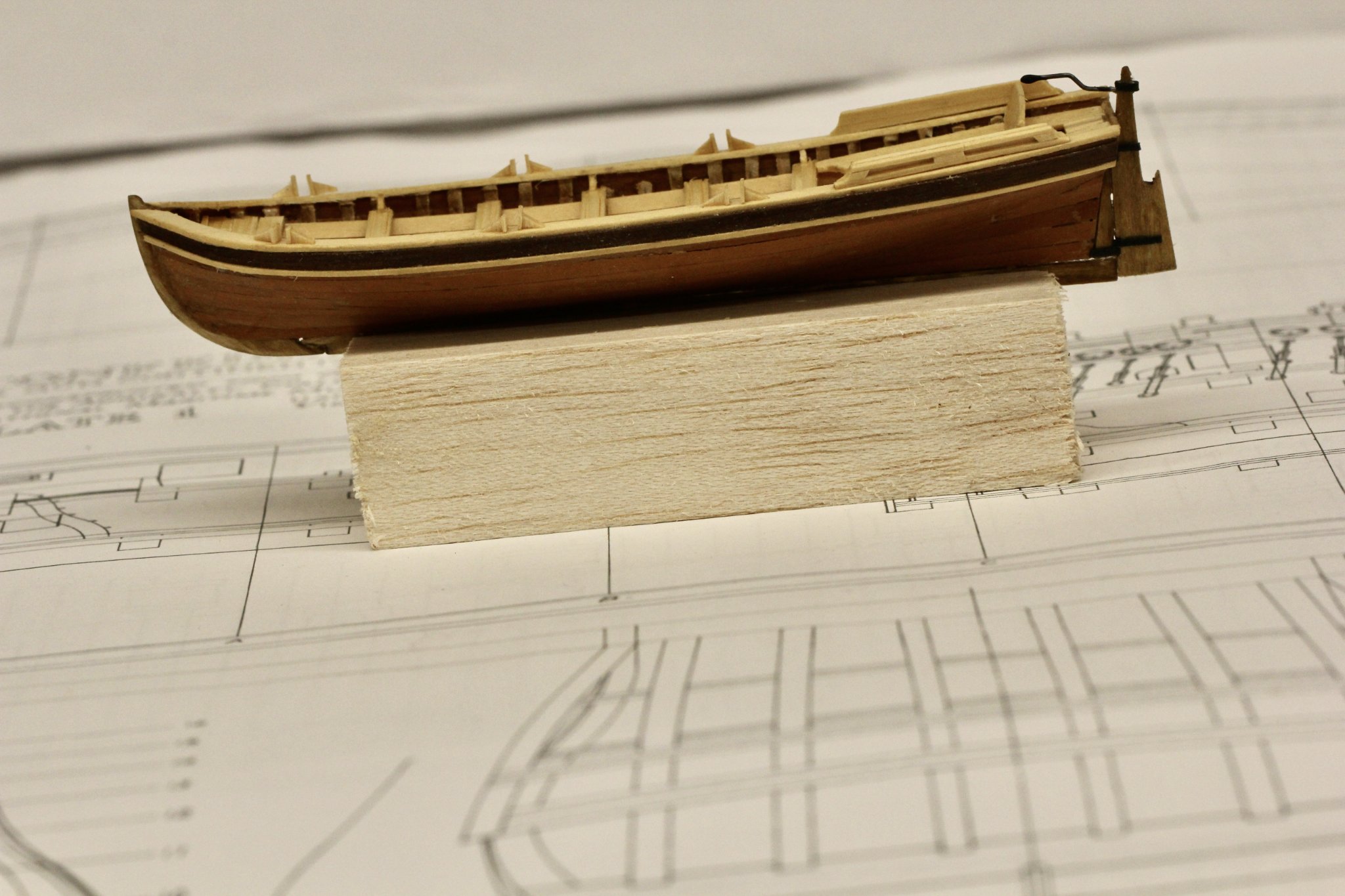
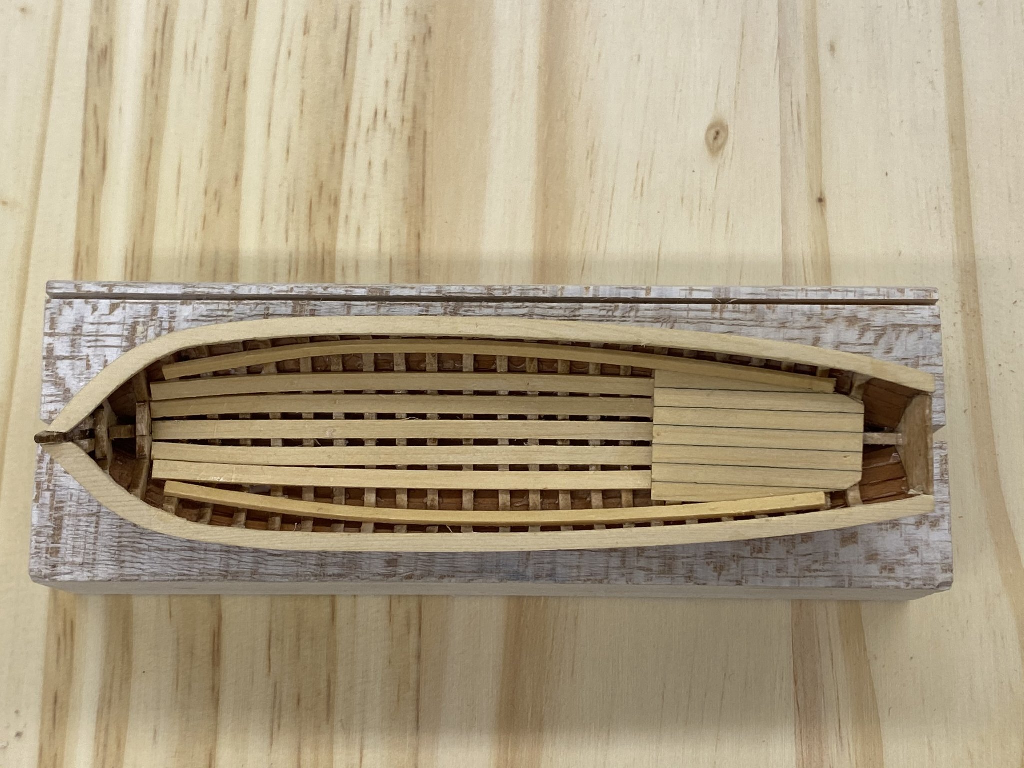
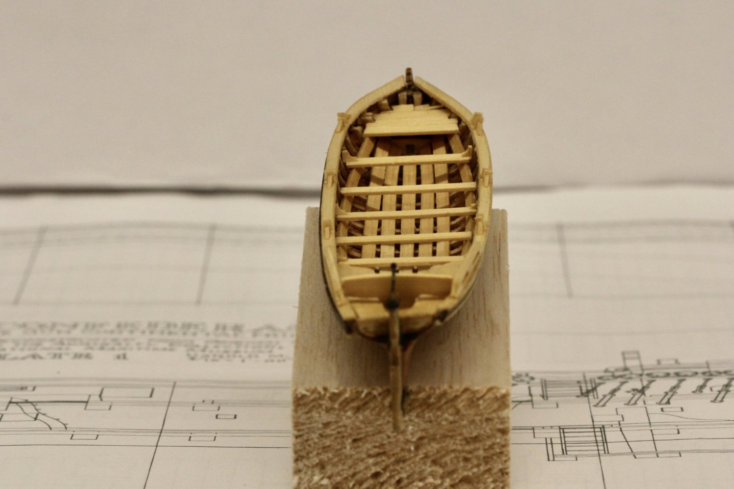
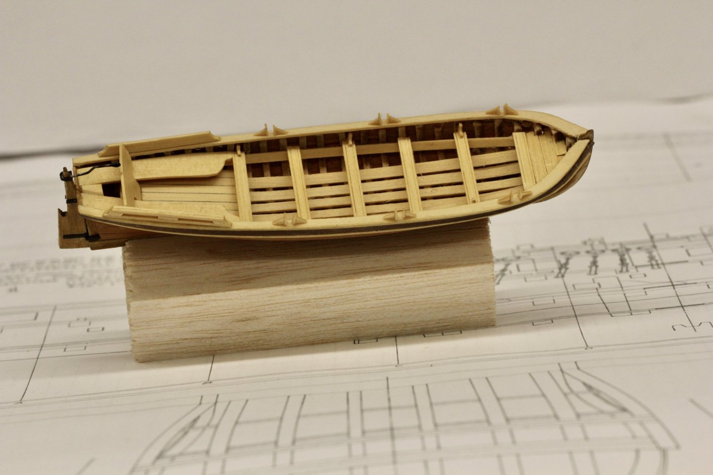
The pinnace is finished. Probably not my finest work, especially on the hull but I will blame that on this being my first experience using Swiss Pear for hull planking. Although I will get a lot more practice as it is my intention to plank the Confederacy with Swiss Pear so I will chalk it up as a learning experience. I used Alaskan Yellow Cedar for all the interior and topside items instead of the kit provided basswood. I think the contrast between the cedar and the Swiss pear helps the boats appearance. It will be interesting to see what they look like when mounted on the finished hull -sometime in the far distant future. I think the walnut above the rub rail worked out well so I will do the same on the longboat which I hope to finish in the next couple of days.


- 370 replies
-
- 5
-
-
- Model Shipways
- Confederacy
- (and 1 more)
-
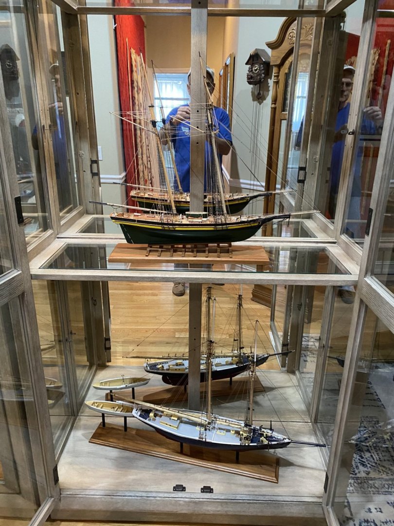
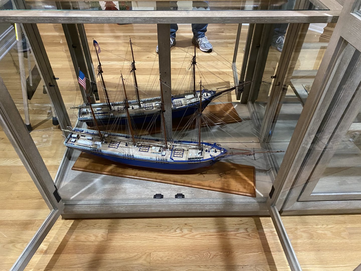
Thanks for the "Likes" everyone. As a follow-up to yesterday's exploits I enlisted my neighbor to help move some more models and cases so I could get two models into the other new display case. So here are the Benjamin Latham and Pride of Baltimore II now "on display". There is an empty shelf above the PoB which is where the Confederacy will reside when it is finished - sometime in the far distant future as it since I have been working for just over two months and have not yet finished the gun carriages and ship's boats - although I am close. Here is a shot of the two display cabinets together. And now back to the boats!
- 370 replies
-
- 7
-
-
- Model Shipways
- Confederacy
- (and 1 more)
-
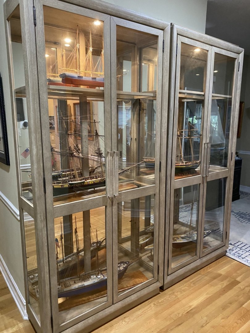
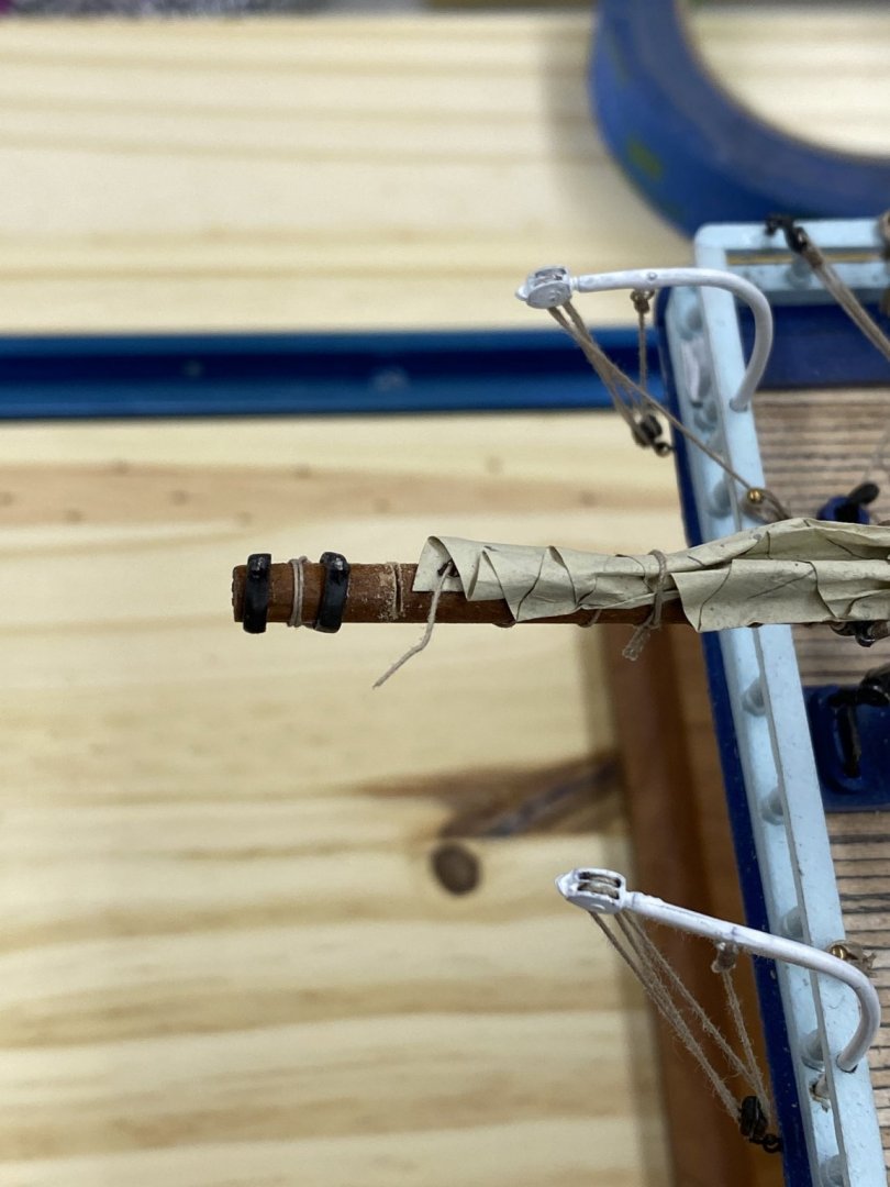
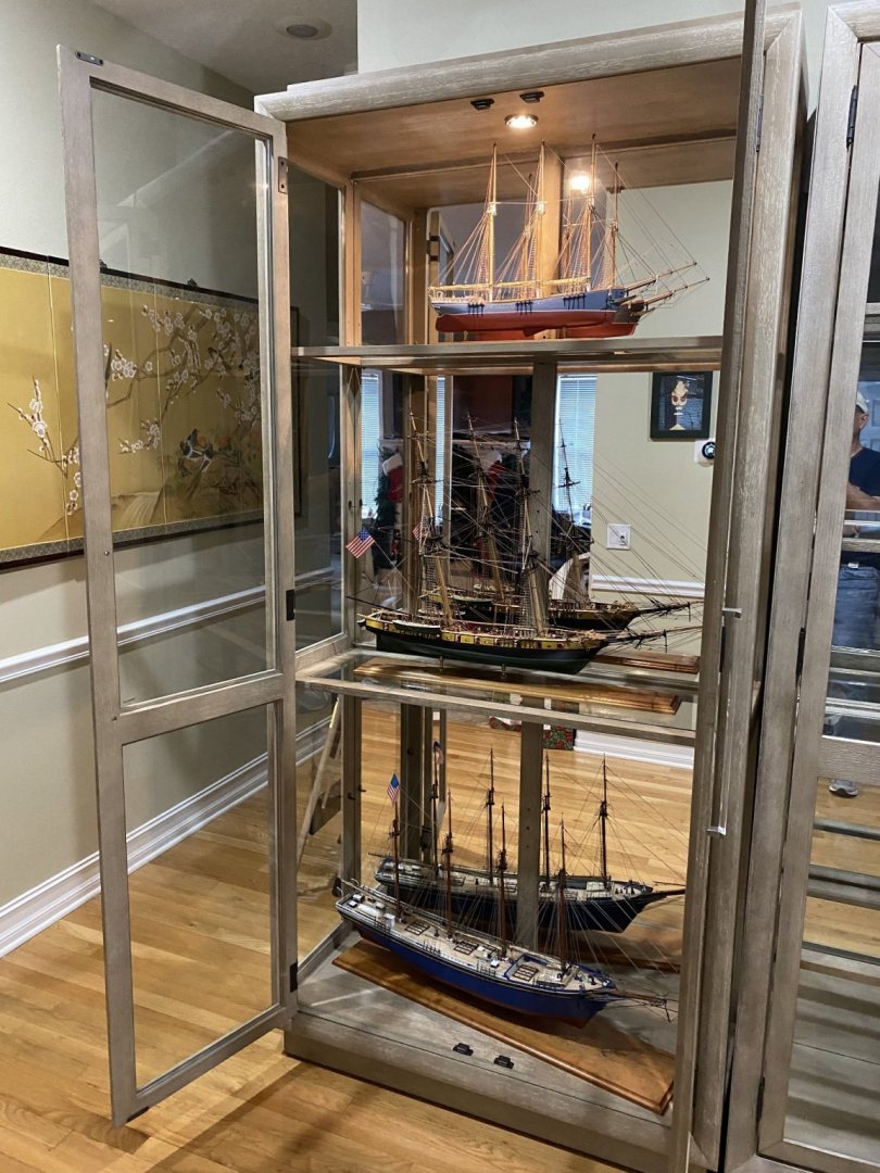
On a slightly different topic. Yesterday I took delivery of two cabinets to house the ship models. I have grown weary of paying at least $500 for a case to store each model in and when by local contractor wanted ~$20K for a custom built-in display case I decided to get something commercially. These cases are 88"high so the 9'+ ceilings come in handy and will hold three ships each, as long as one of them isn't very tall. It is hair over 40" from glass to glass on the inside which became an issue with my Notman model. It would not fit (even diagonally ) without both the boom and bowsprit against the glass. So, now the Notman's boom is about an inch shorter than it should be. You can see how much I took off in the photo below. But it in now successfully in its new home (still needs to be in diagonally). And so are the Gorham and Niagara. So now back to work on the Confederacy which will have the top shelf in the other cabinet.
- 370 replies
-
- 8
-
-
- Model Shipways
- Confederacy
- (and 1 more)
-
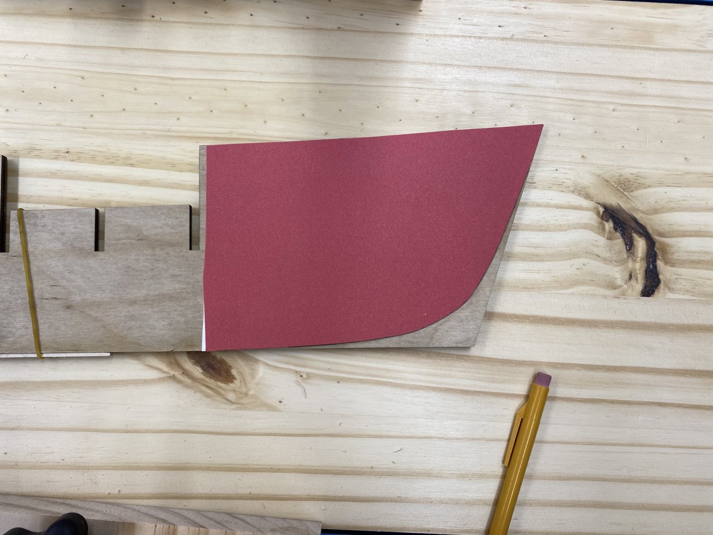
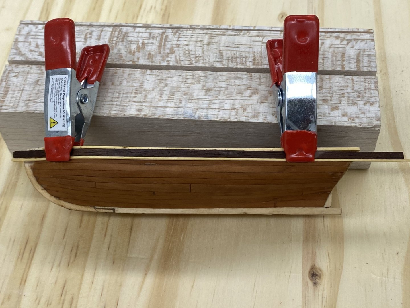
While waiting for glue to dry I took a piece of walnut and thinned it down to something less than 1/32" (~.0250 about half way to 1/64") X 3/32" and a piece of Alaskan cedar (1/32" X 1/32") as the rub rail and clamped them to the side of the longboat to see what it would look like. I rubbed it with paint thinner to approximate what the WoP will do to darken the wood and this is what it looks like. I am putting the rub rail on the pinnance now and I think I will use the walnut instead of black paint. I am not sure the paint would "work" with the Swiss Pear planking.
- 370 replies
-
- 3
-
-
- Model Shipways
- Confederacy
- (and 1 more)
-
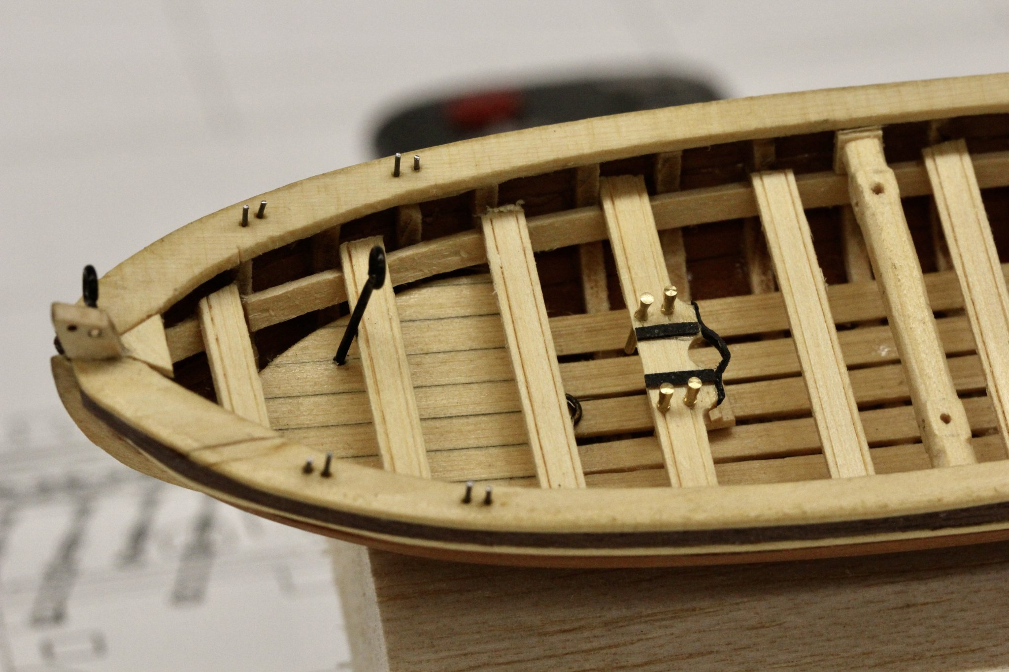
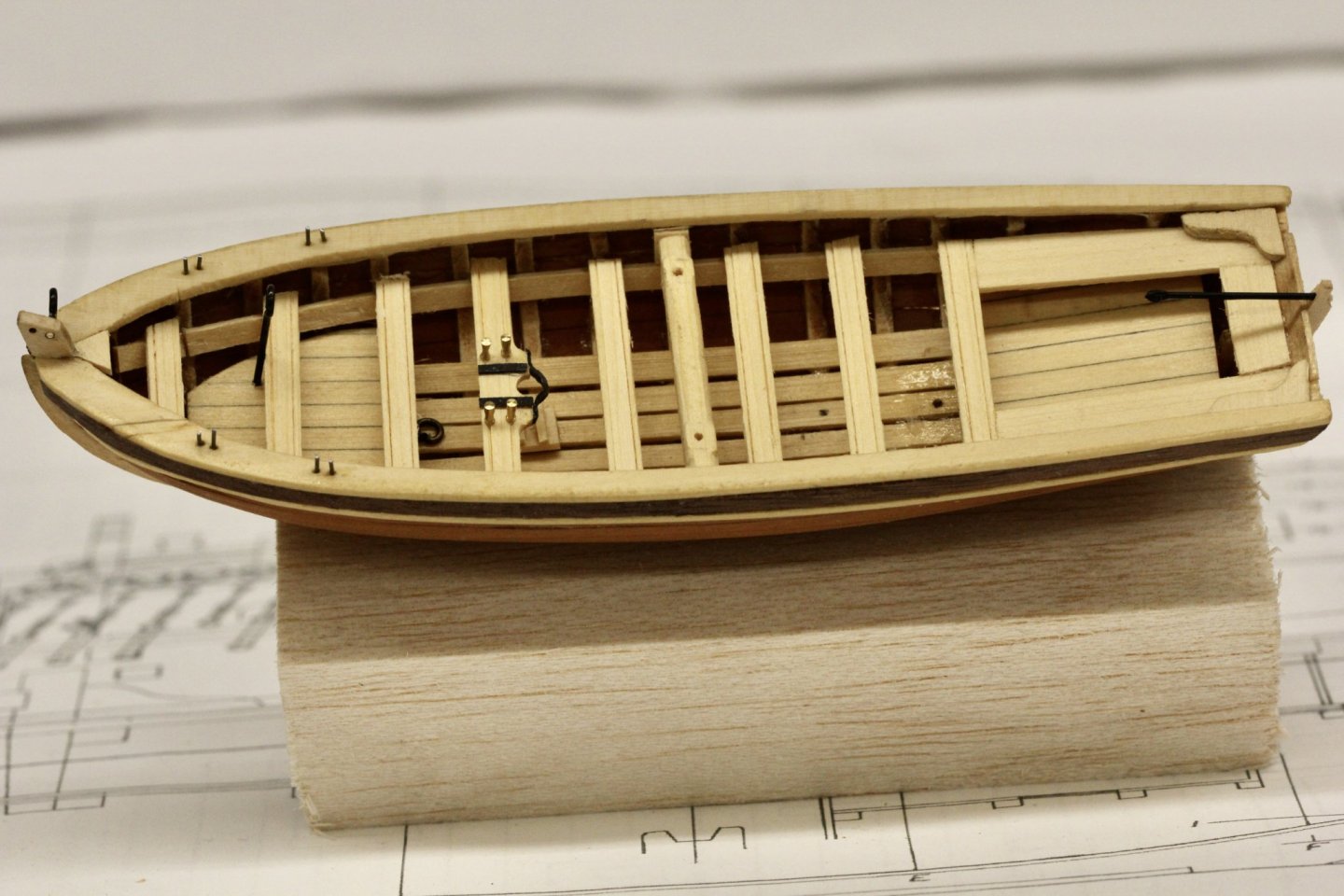
Thanks Bossman. My plan is to finish both the pinnance and longboat before starting on the "real" model. Here is the pinnance with the floor boards, thwarts, cap rail and rear platform installed. I put a coat of Tru-color TCP-017 Flat on the pinnance interior. It will be much harder to get everything covered after the seats and other interior parts are installed. I will use Wipe-on-Poly on the exterior as I am more familiar with it and it is easy to apply to the outside. I am hoping the aft platform is really on straight and it looks off because of the way I took the picture - parallax or something like that.

- 370 replies
-
- 1
-
-
- Model Shipways
- Confederacy
- (and 1 more)
-
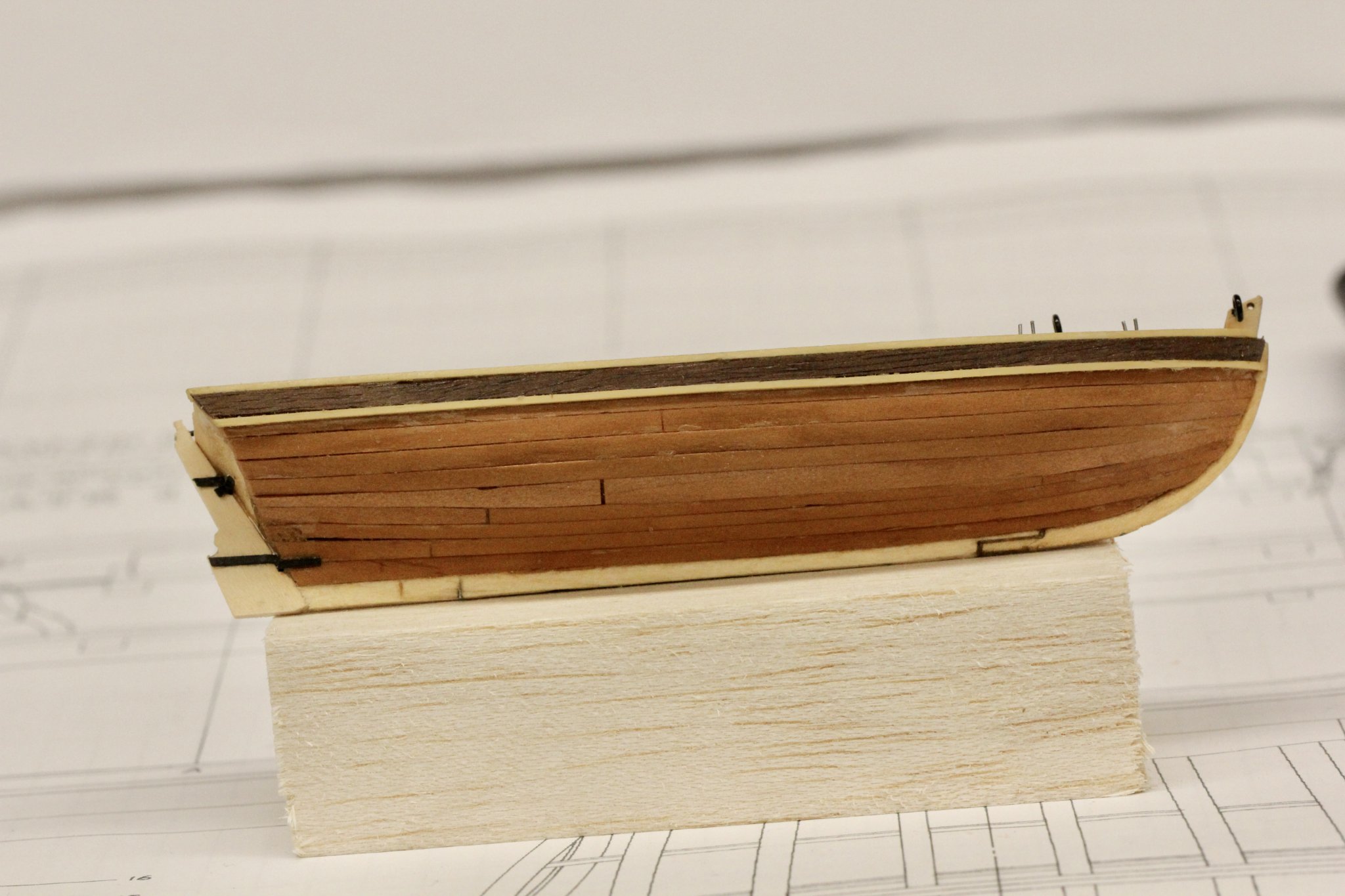
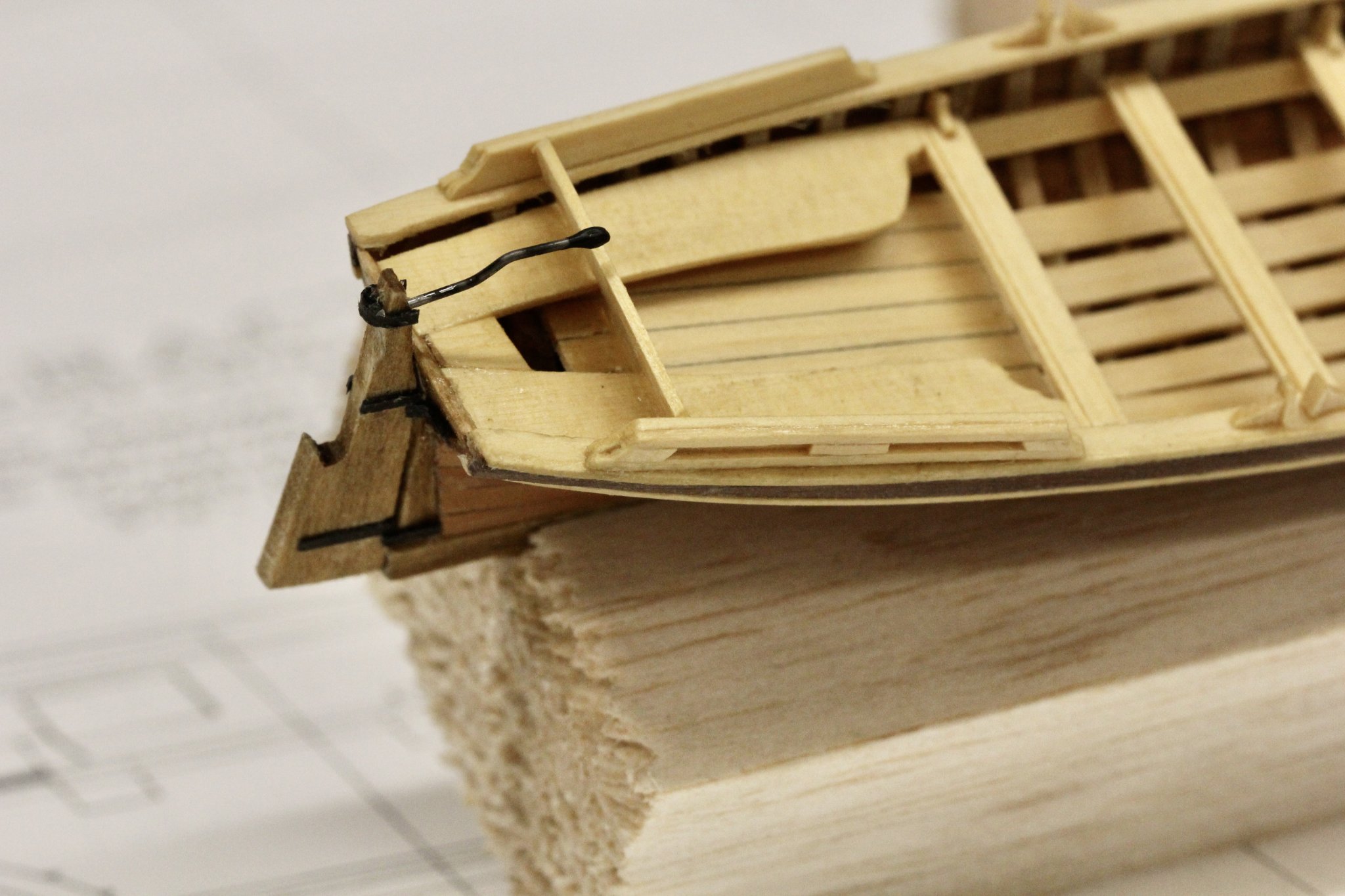
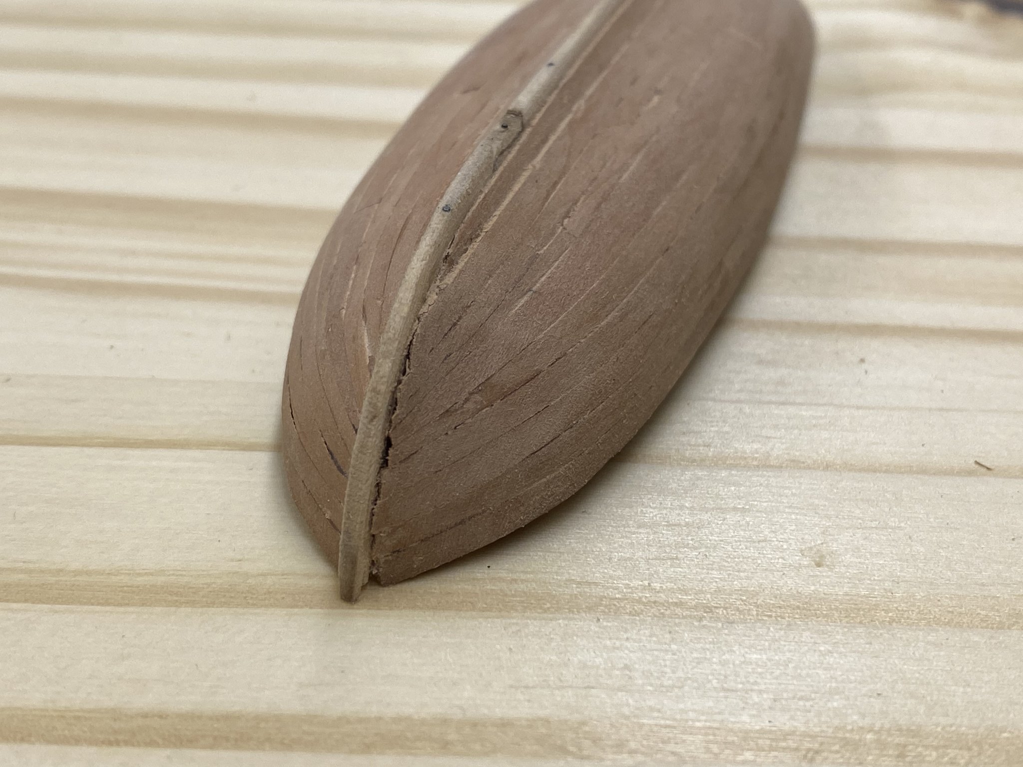
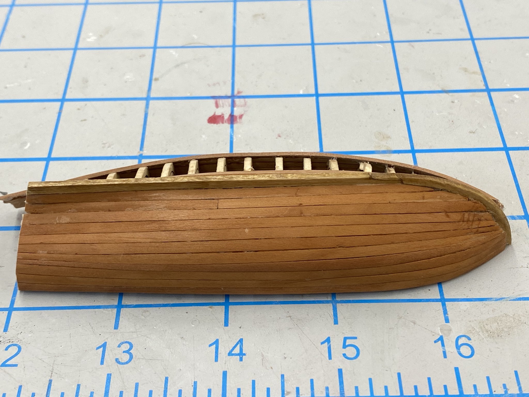
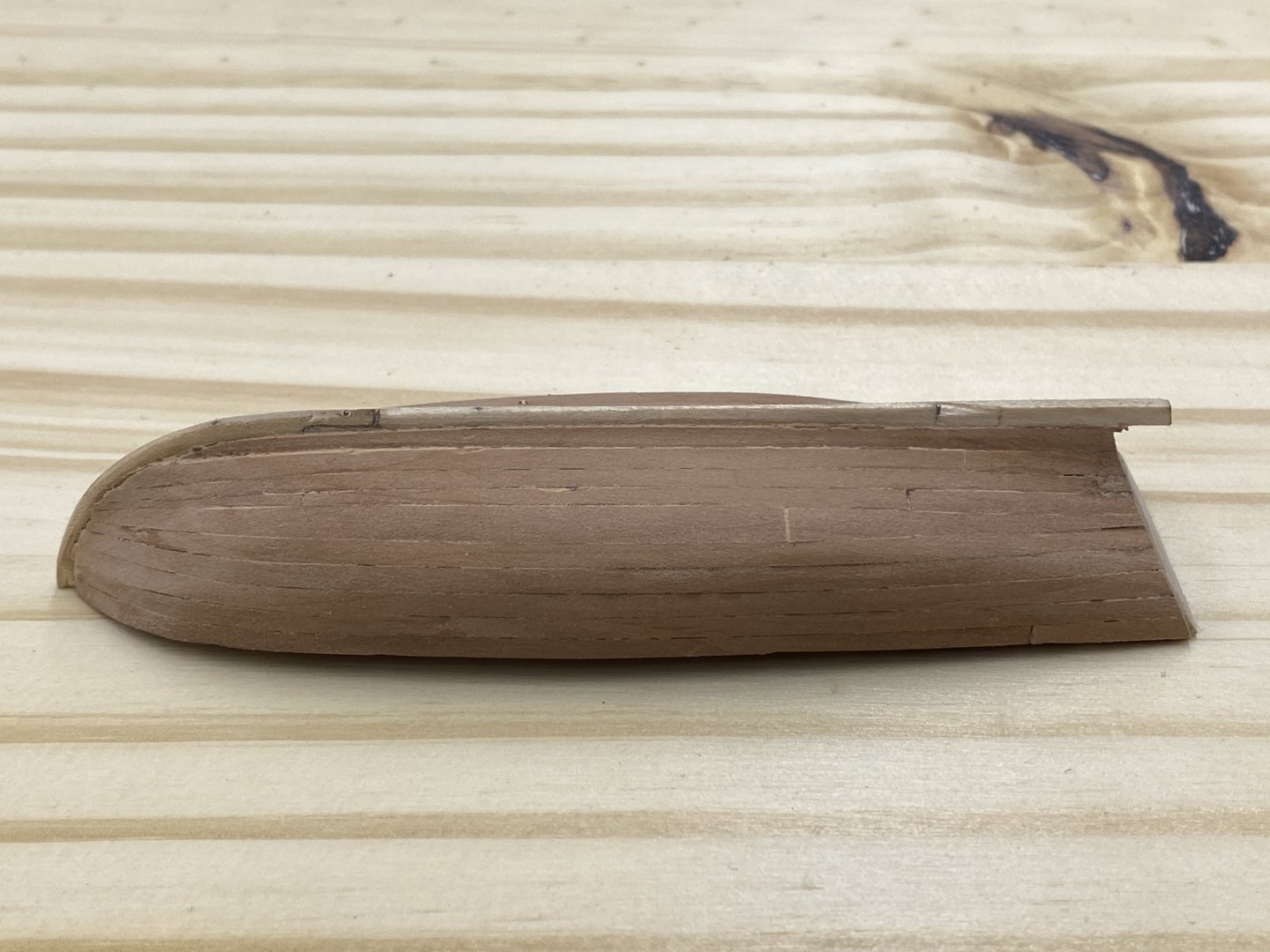
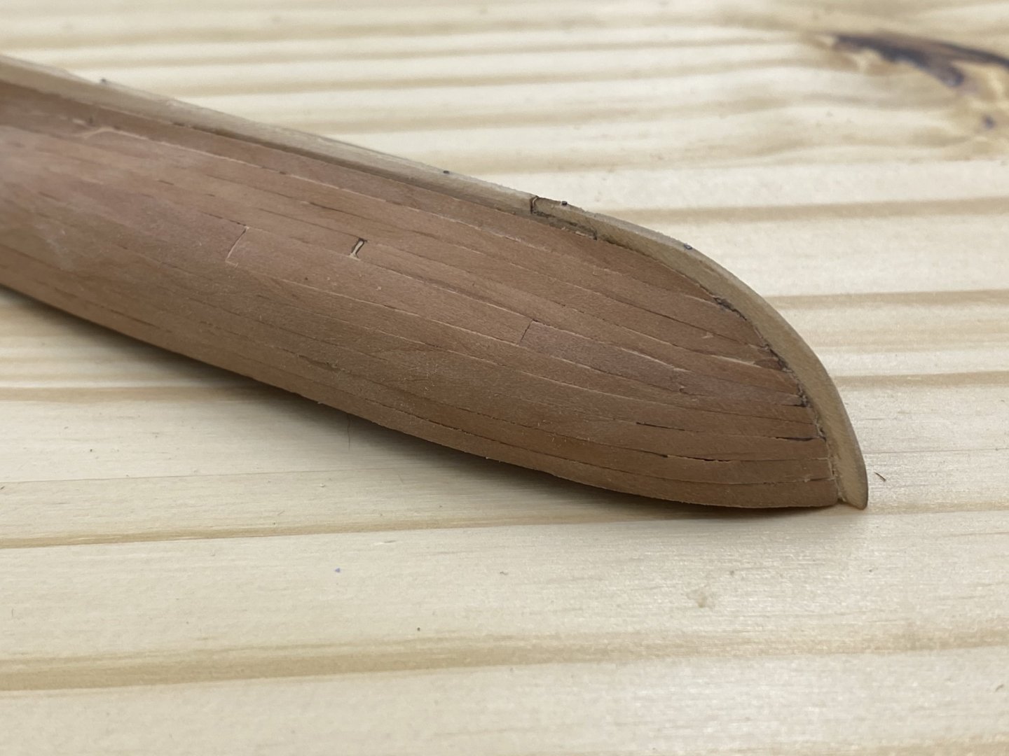
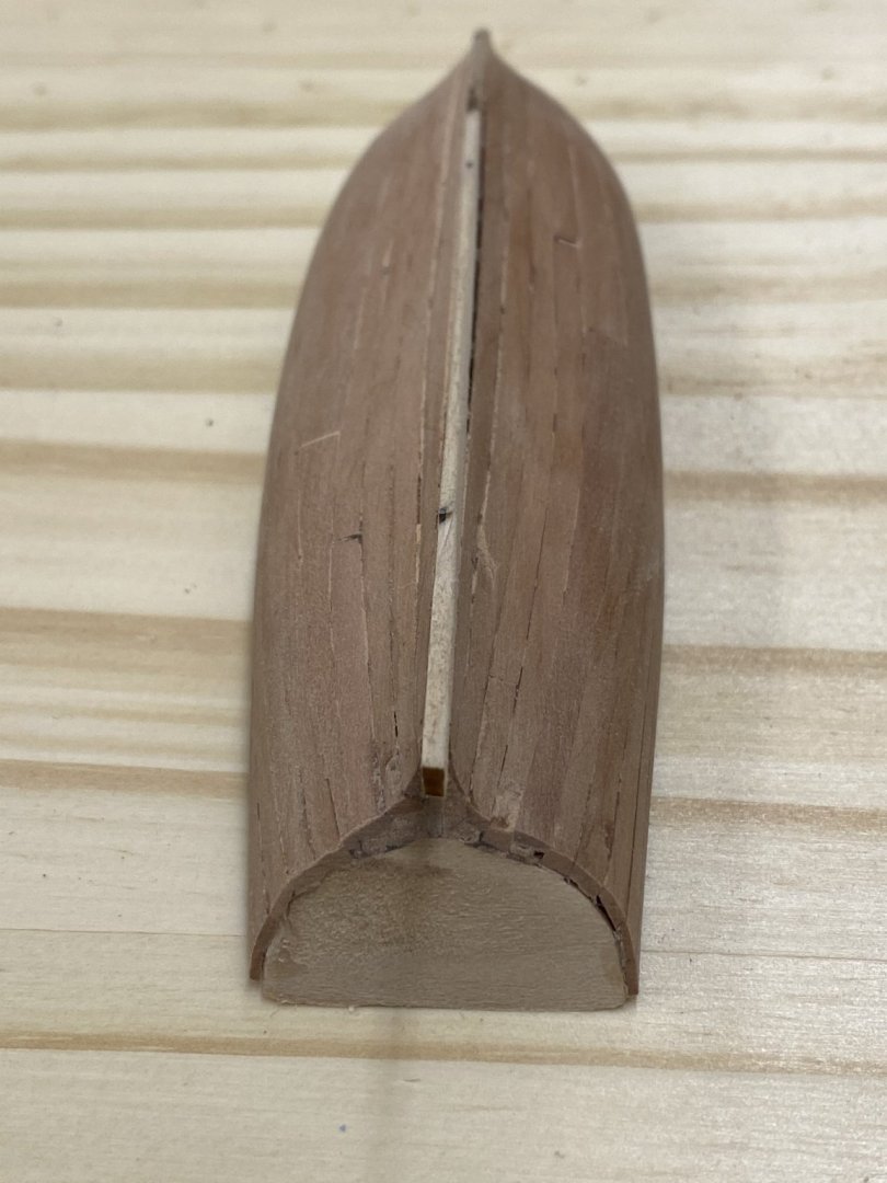
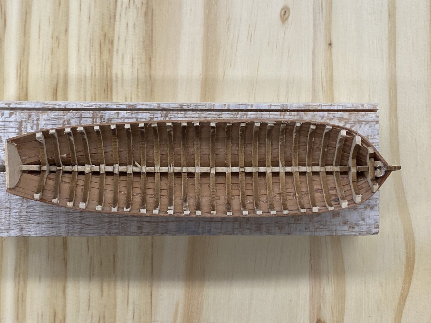
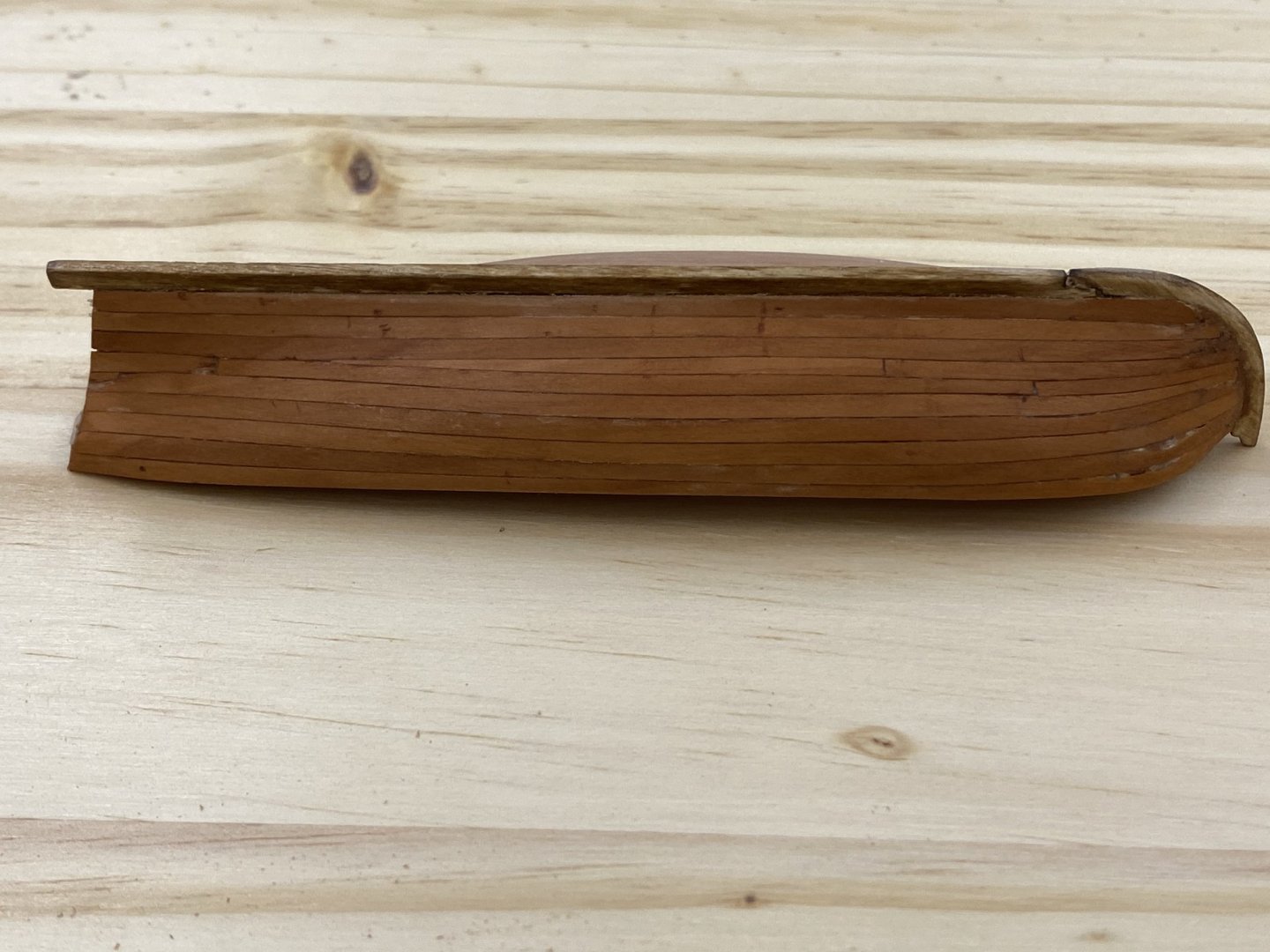
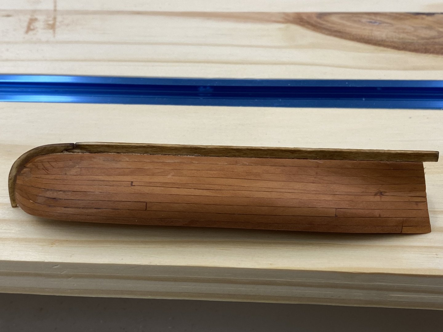
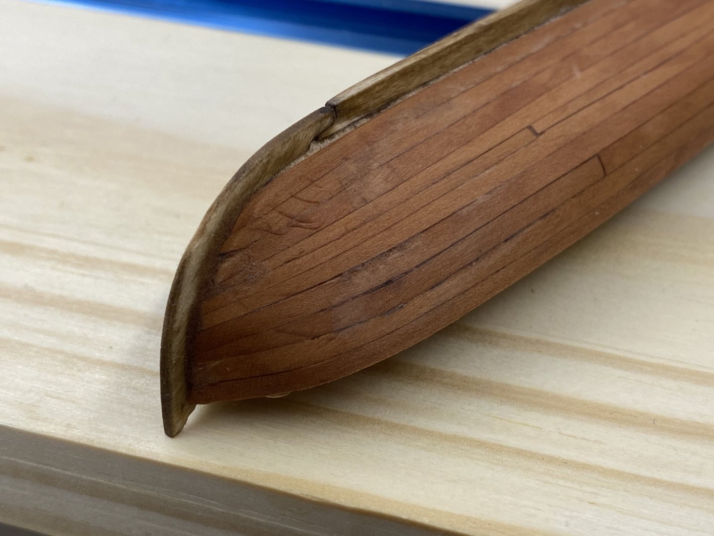
So that was the pinnance. Here is the longboat. Unlike in the pictures above of the pinnance which were taken shortly after wiping the hull down with paint thinner, these pictures were taken with the hull in its "natural" unfinished state. My plan is to give the hulls (and other external parts (keel, rudder, cap rail, etc.) three coats of Wipe-on-Poly satin once all the external parts are onboard. I am unsure what I will do about the interior. I am going to use Alaskan Cedar for the interior components (floorboards, thwarts, decking, etc.) since I have a bunch left over from a previous kit (Endeavour I think) and I think the light color will make a nice contrast with the darker Swiss Pear hull. I am undecided on the black strip with between the cap rail and the molding just below. I want to see what the hull looks like with the different wood tones before I make that decision. I have some walnut strips which I could thin down and use instead of paint if the dark strip looks like it will improve the boats appearance. I thought ahead and saved part of the swiss pear sawdust that I generated and combined with 50/50 glue water used it to make a patching material which I found was needed at the stern. I could not get the planking to twist as much as required in spite of the water (and I even used a bit of steam too). Much of this will be nearly invisible behind the rudder but I you can't have obvious holes below the waterline (even if they would be very hard to see). So here is the long boat with the bulkheads removed and a first pass at fairing and removing the laser char. You can see several of the pins I used to attach the keel/stem and false keel. At least I did not break the keel off with a planking clamp like I did on the pinnance. Pins probably helped.

- 370 replies
-
- 3
-
-
- Model Shipways
- Confederacy
- (and 1 more)
-
I can't believe that it took more than 10 days just to get the two ship's boats planked. It was slow going and I am really not satisfied with the results but have decided to press on. It will be a long time before I need these on the build so maybe they will "grow on me". Anyway, here is the pinnance with the planking completed, sanded and the bulkheads removed. I used Swiss Pear strips (3/32' X 1/32") to plank the hull instead of the similarly sized basswood strips included in the kit. I manged to sand through the planking at two places on the stbd side of the bow and the joint between the keel and stem is not as "pretty" as it should be but I managed to snap the keel off the h ull while using it to support one end of several clamps holding a hull plank in position. As you can see from the interior shot, there are several ribs where some portion of the upper part has broken off. Before I try and get the laser char off the ribs I am going to try and fashion some replacements. Hopefully much of the upper part of the ribs will be hidden by other interior components but it is hard to tell at this point which ones. I have one more plank to finish on the longboat so it is not yet "ready for pictures".


- 370 replies
-
- 4
-
-
- Model Shipways
- Confederacy
- (and 1 more)
-
Tim, You are welcome. 2mm will be even trickier than the 2.5s. I might think about going with 34 gauge wire but it is possible to actually cut the block in half if you try and get the wire too tight. And the thinner the wire and smaller the block the more that can be a problem. Don't ask me how i know.
-
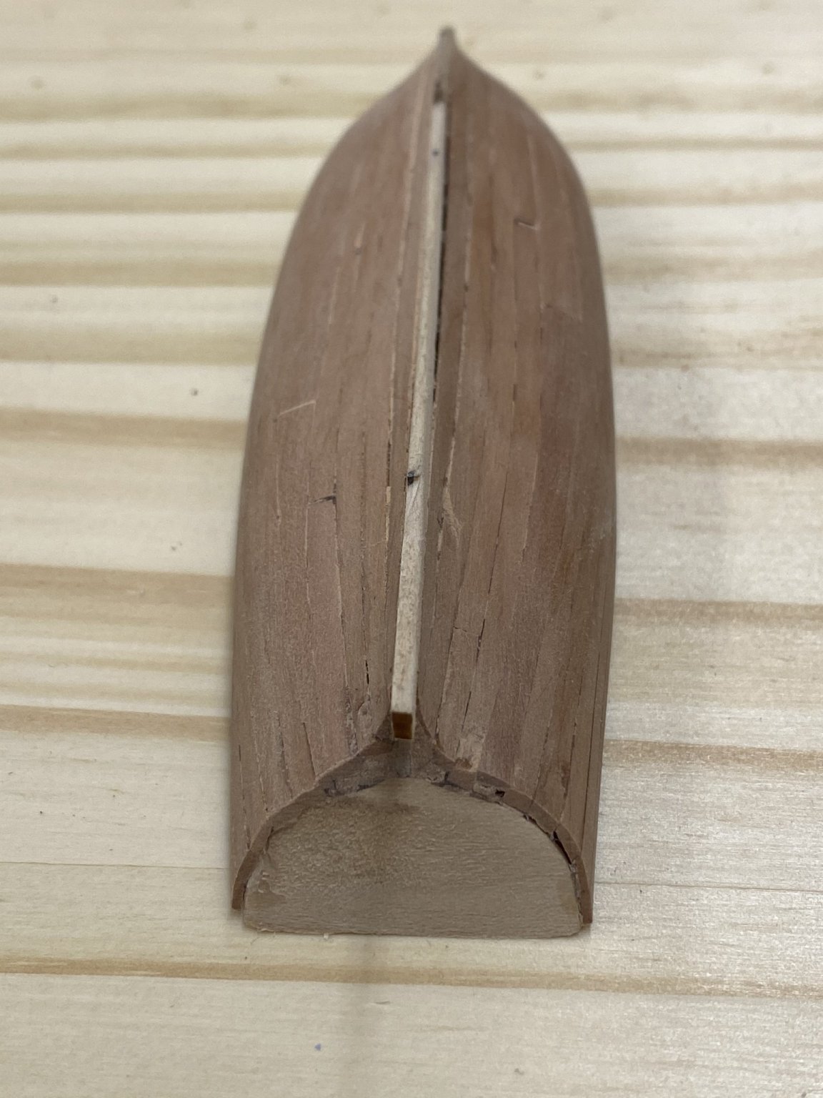
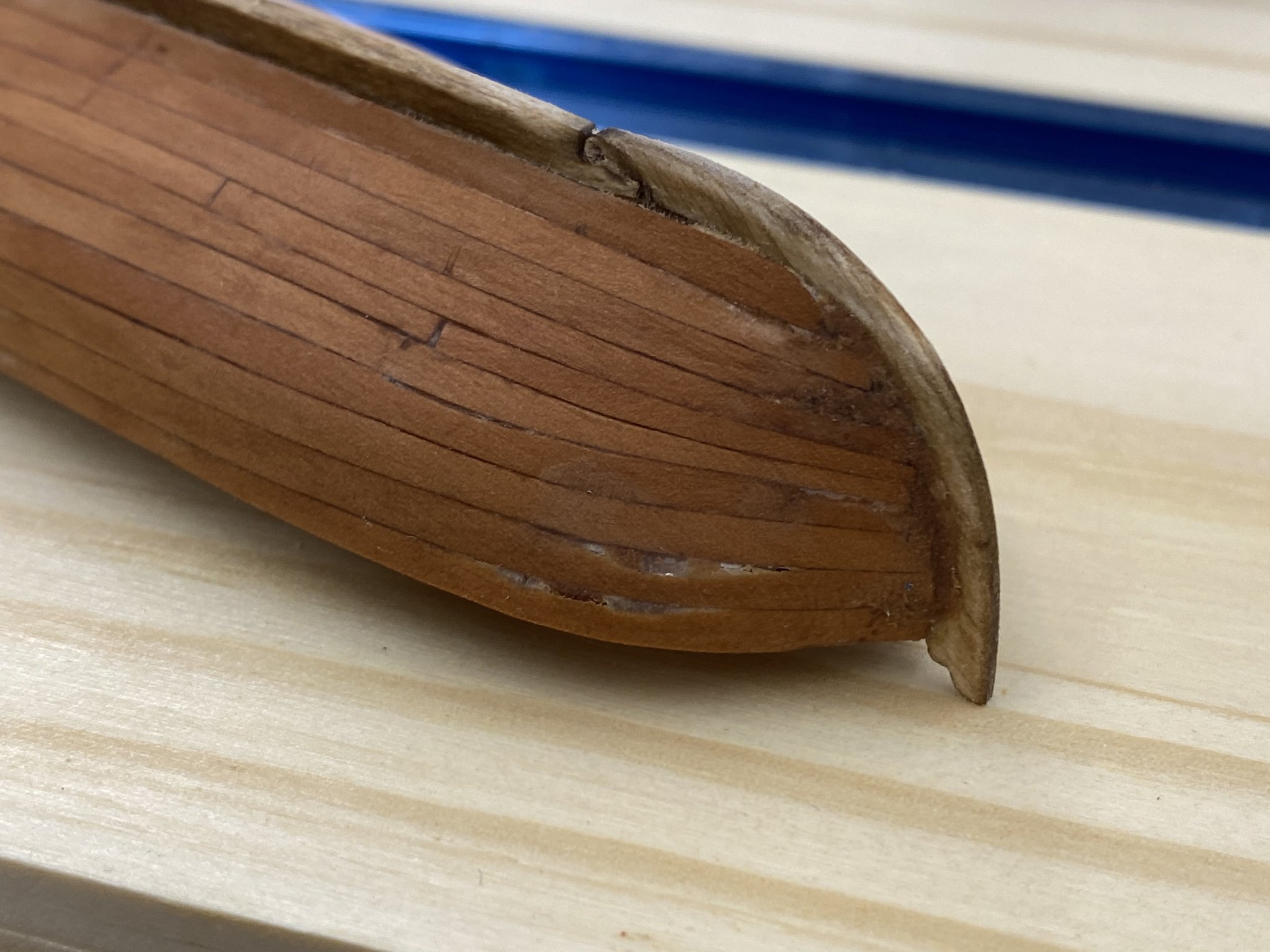
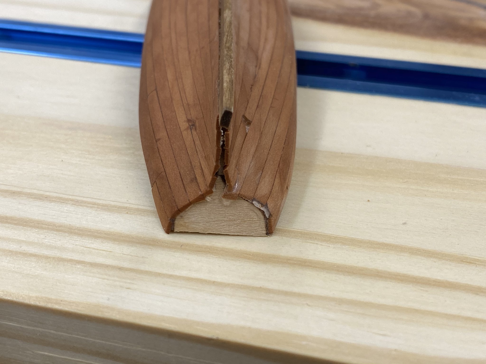
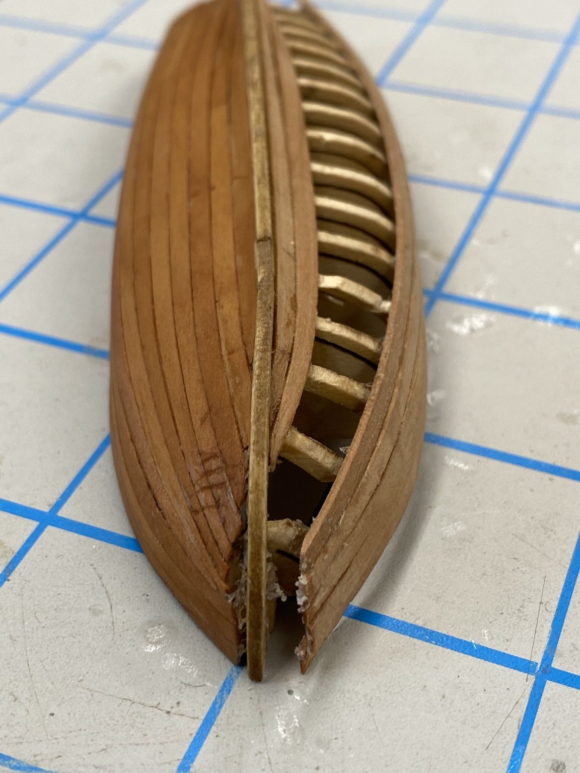
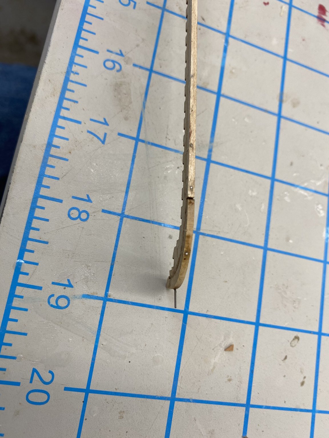
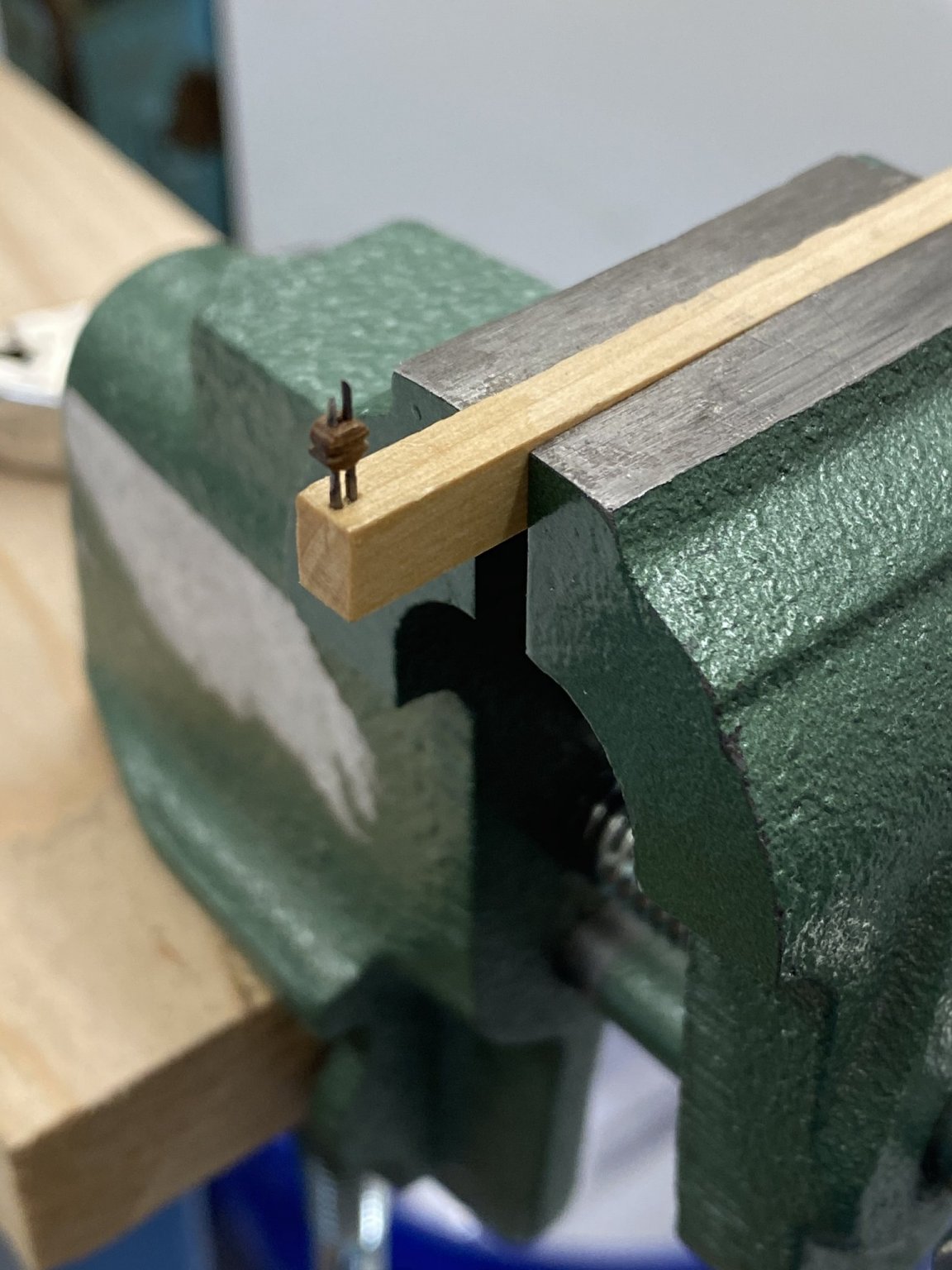
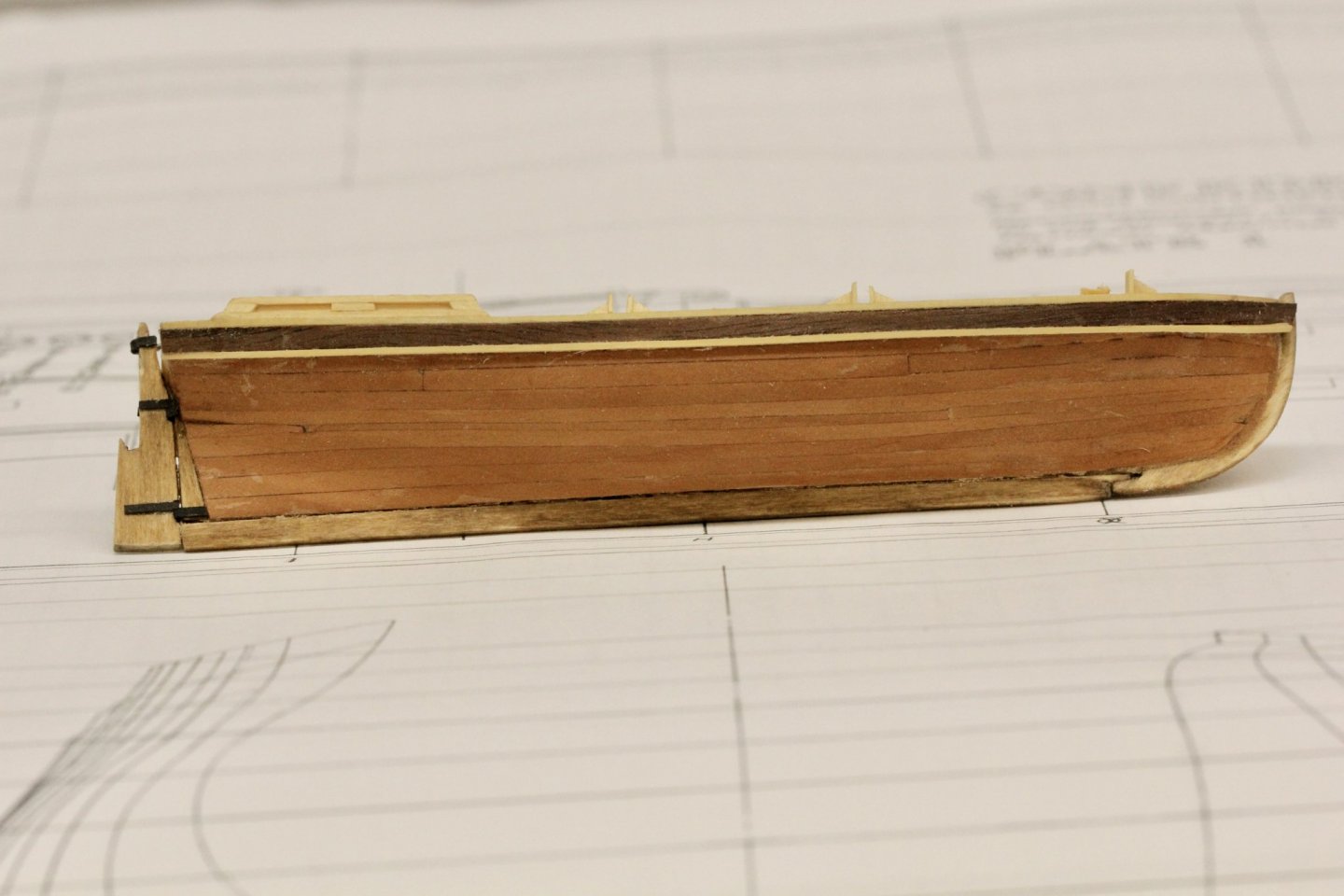
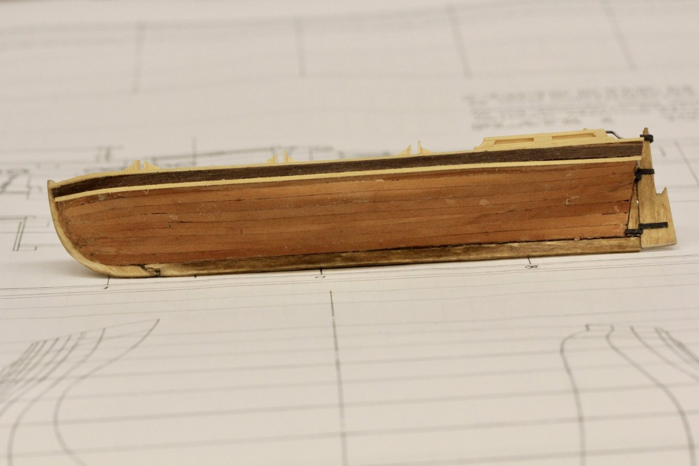
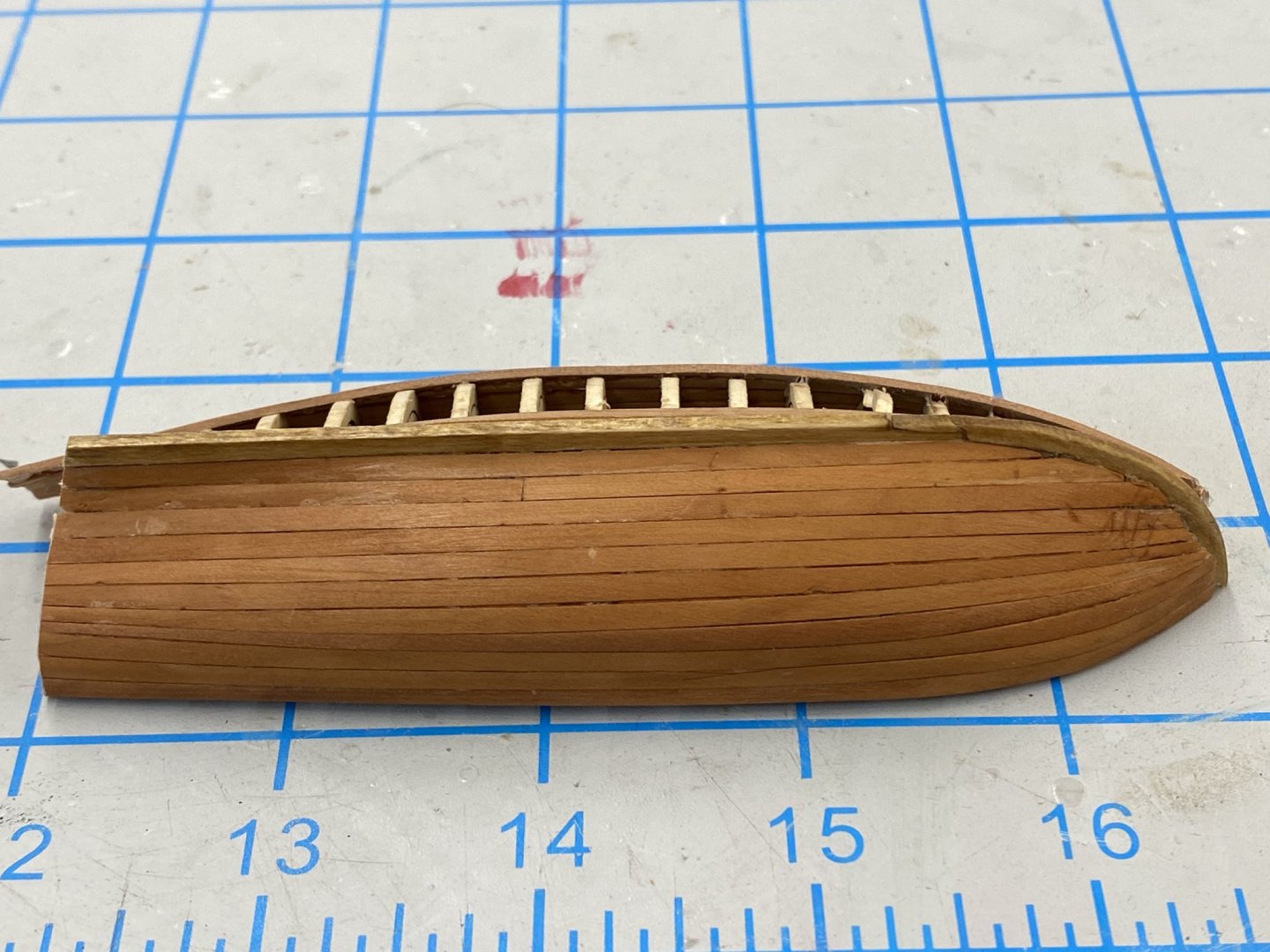
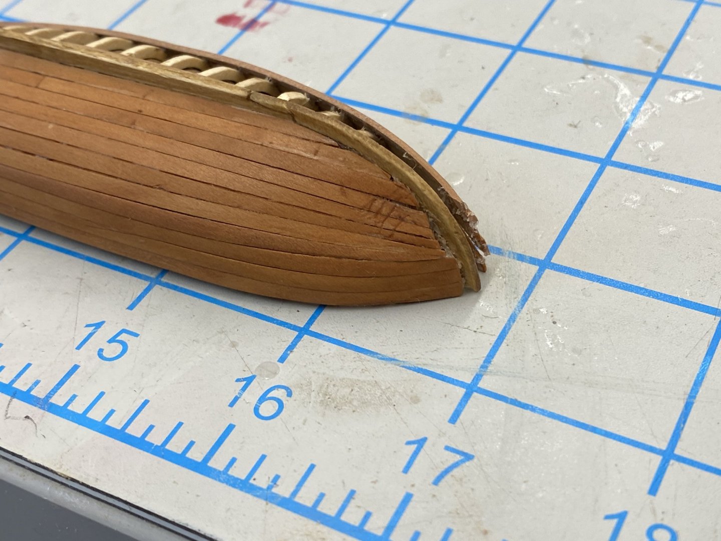
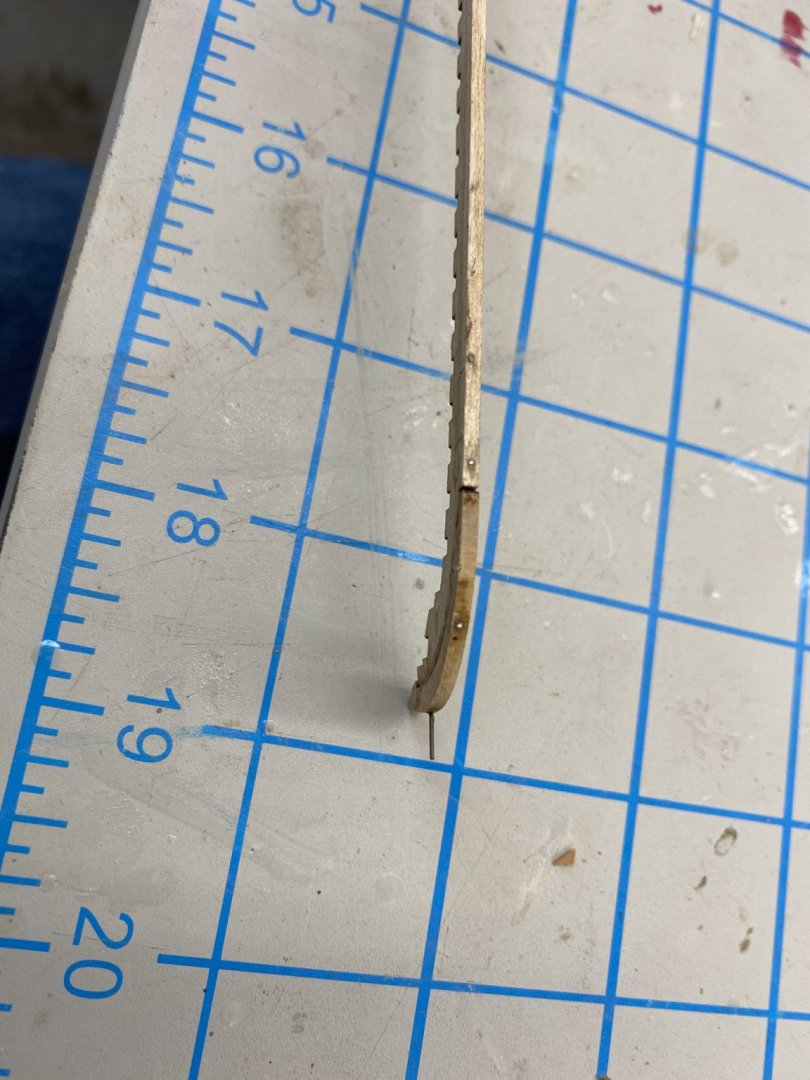
I have been having problems getting the ship's boats hulls finished. I got the bearding line sanded into the false keels and the false keels and keels assembled and used the build board to hold these assemblies while I glued in the bulkheads. I was somewhat disappointed in the apparent flexibility of the bulkhead/keel assembly, even with a strip of planking on each side so I added a 1/32" X 1/8" plank down the center of the bulkheads (which will be removed before extracting the bulkheads after planking). The planking process did not go as smoothly as I had hoped. Even though I used 320 grit sandpaper to fair the bulkheads I still managed to take chips out of a bulkhead or two on each hull, plus taking entire ribs off their bulkheads in two places. These I glued back as best I could but the small (a plank or two wide at worst) pieces I left to deal with after the hull is planked and bulkhead removed. I managed to get one side of the long boat completed and two coats of Wipe-on-Poly to get an idea of what it will look like with the Swiss Pear planking. Here it is: Not too bad although I clearly did not start tapering the planks at the bow soon enough. Those diagonal marks at the bow are from pressing the planks to hard with my fingernail (I think). You can also see in the photo below that I did not get a good joint between the hull planks and the keel/false keel in a couple of places. There are also some gaps between planks but they do not show up very well in the photos and are hard to see in person unless you can get the light behind the planks. Something to think about for the pinnance. Here is what I am talking about: The real problem is on the starboard side. Here all the hull planking has pulled away from the keel and the removable part of the two forward bulkheads had become detached - probably due to using clamps to try a get the planking glued to the keel.Here is what this side looks like. One other thing to notice here is the the stem/keel is no long straight. Because there is only 1/16" of material to start with, when you remove material for the bearding line (groove) it leaves less material to form the joint between the false keel and keel. In trying to get the planking clamped to the false keel I managed to open this joint. So this will not be one of the ship's boats - although it was a learning experience. One lesson was that there needs to be more "beef" in the keel/stem/false keel joint, at least on my boats. So after gluing the pinnance keel/false keel together I drilled #76 holes through in several places and pushed .020" piano wire through the holes, put a drop of thin CA at each place and then cut/ground off the excess wire. Here is a shot of the pinnance keel/false keel with one of the reinforcing wires still to be cut off. and the shiny ends of some of those already cut off visible. Hopefully this will make it more difficult to "dislocate" the stem from the false keel.

- 370 replies
-
- 2
-
-
- Model Shipways
- Confederacy
- (and 1 more)
-
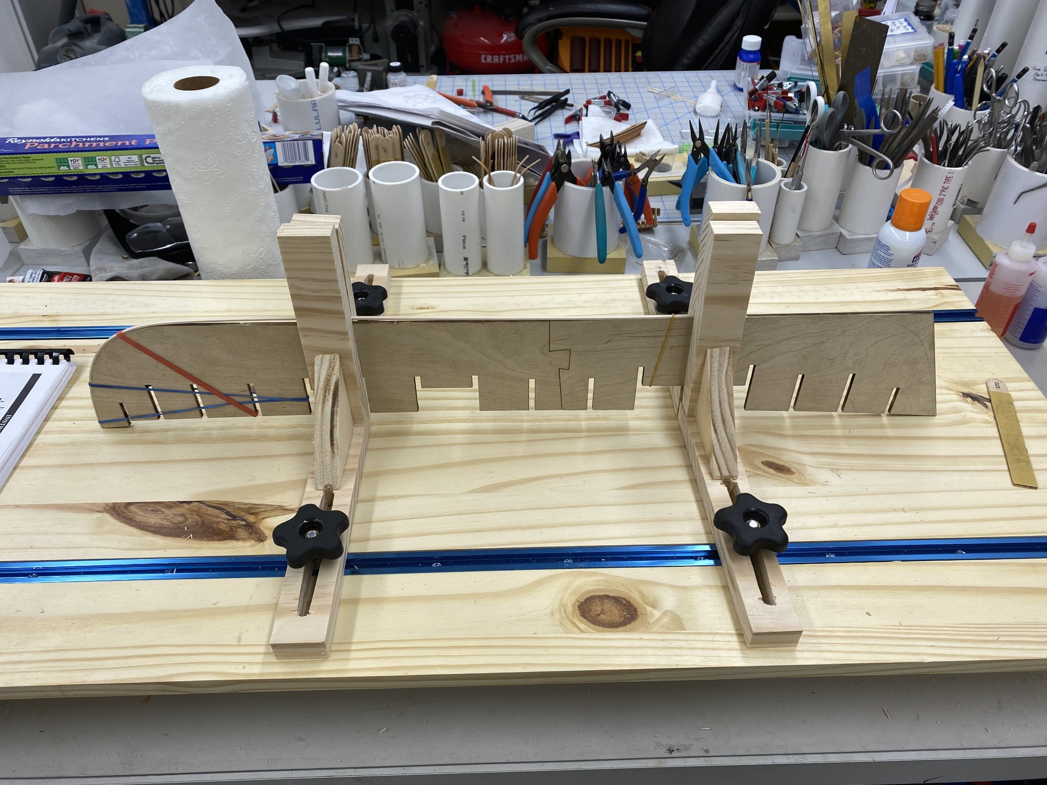
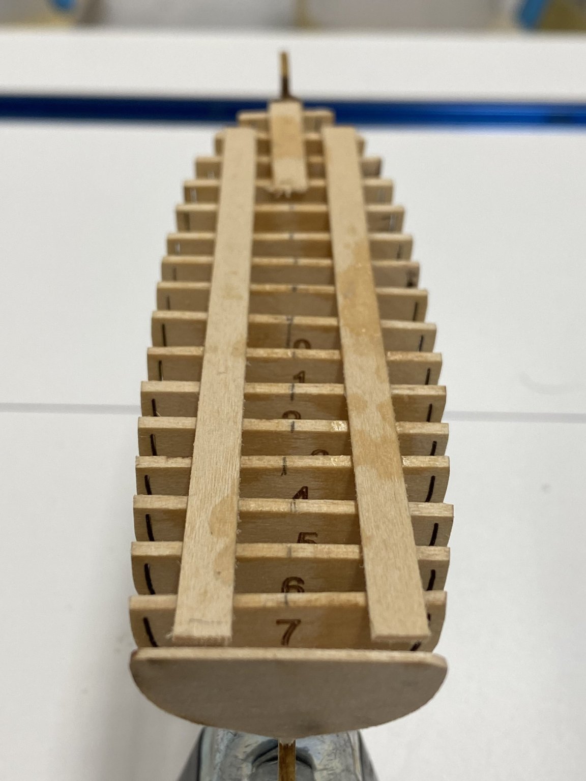
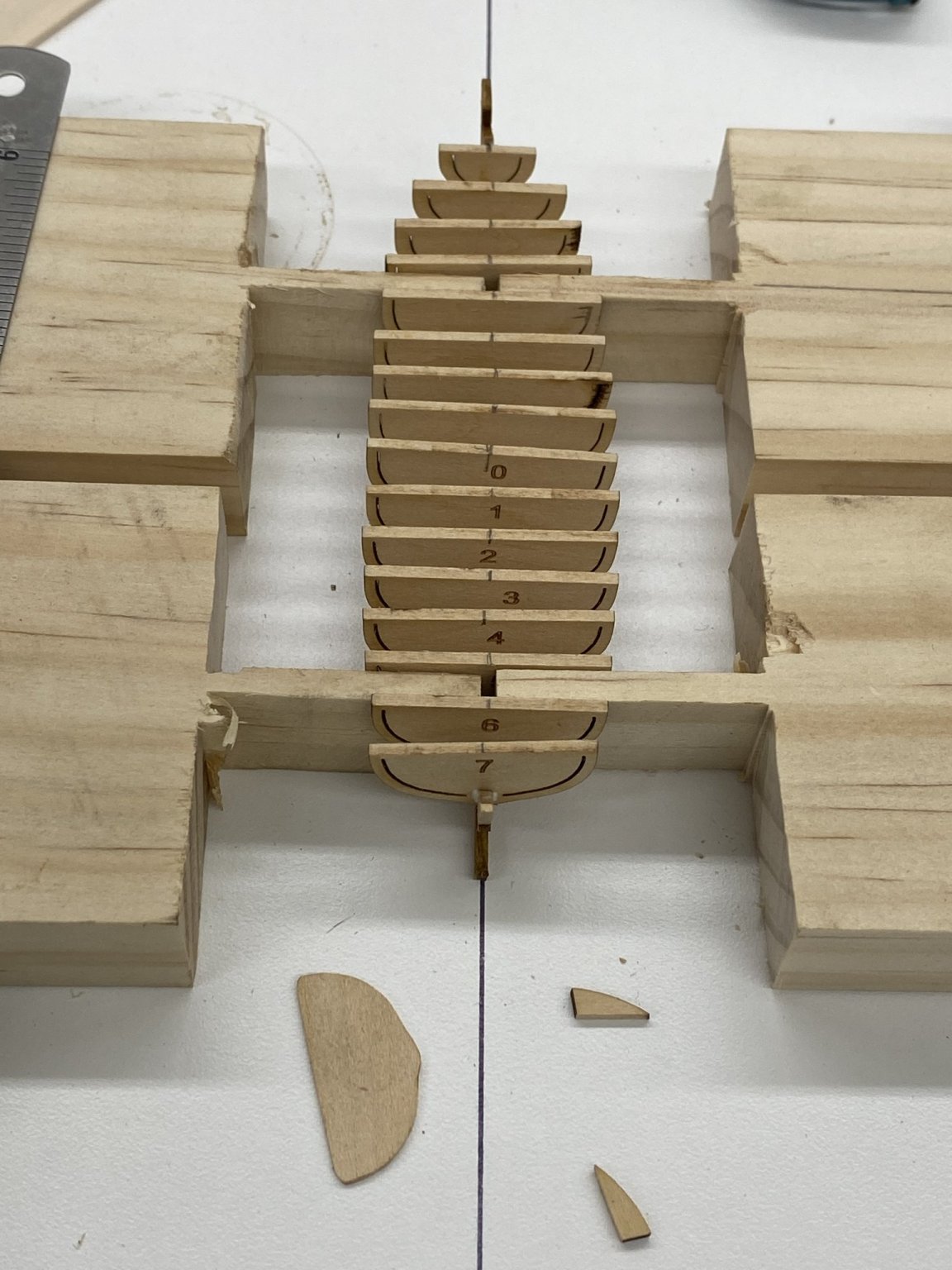
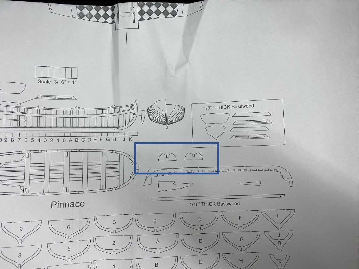
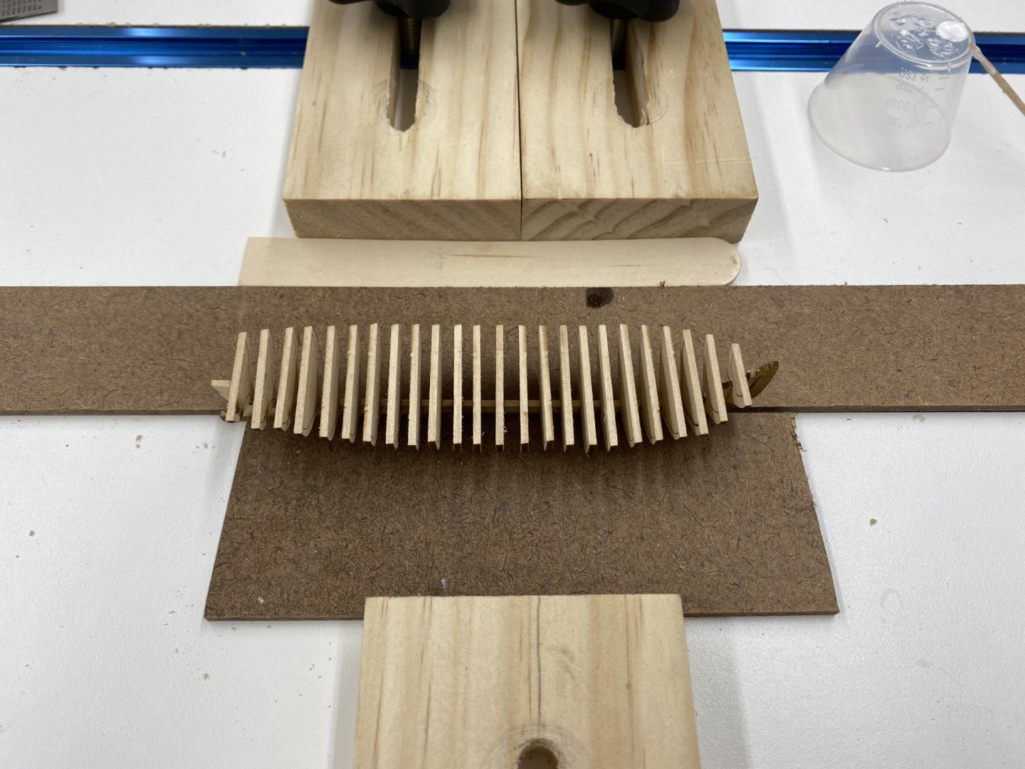
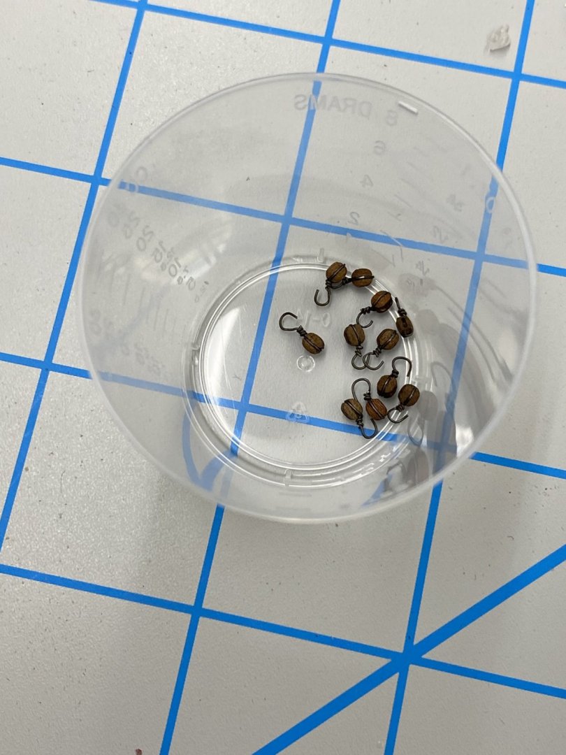
The rest of the 2.5mm blocks for the gun tackle arrived today so I have been moving from gun tackle to longboat planking and pinnance bulkhead installation. I got to the end of the pinnance bulkhead installation and looking at the drawing noticed I could not locate where the two "extra" items (outlined in the picture below) are located. Can anyone shed any light on this? I decided to change to fixture I used to hold the false keel for the pinnance. It is longer than the longboat and the fixture I used for the longboat would not allow access to all the slots for the bulkheads. So I resorted to supporting the false keel along to bottom (the "real" keel actually). As you can see below this allows access to all the bulkhead slots. It also makes it easier to sight down the bulkheads to keep things aligned although there is still some "wiggle" in the false keel so it times it is hard to tell if you have made an actual movement of the bulkhead or just twisted the false keel. Here is a shot of the pinnance with all the bulkheads installed. Here are the first ten of the 2.5mm gun tackle blocks without the becket and line.
- 370 replies
-
- 2
-
-
- Model Shipways
- Confederacy
- (and 1 more)
-
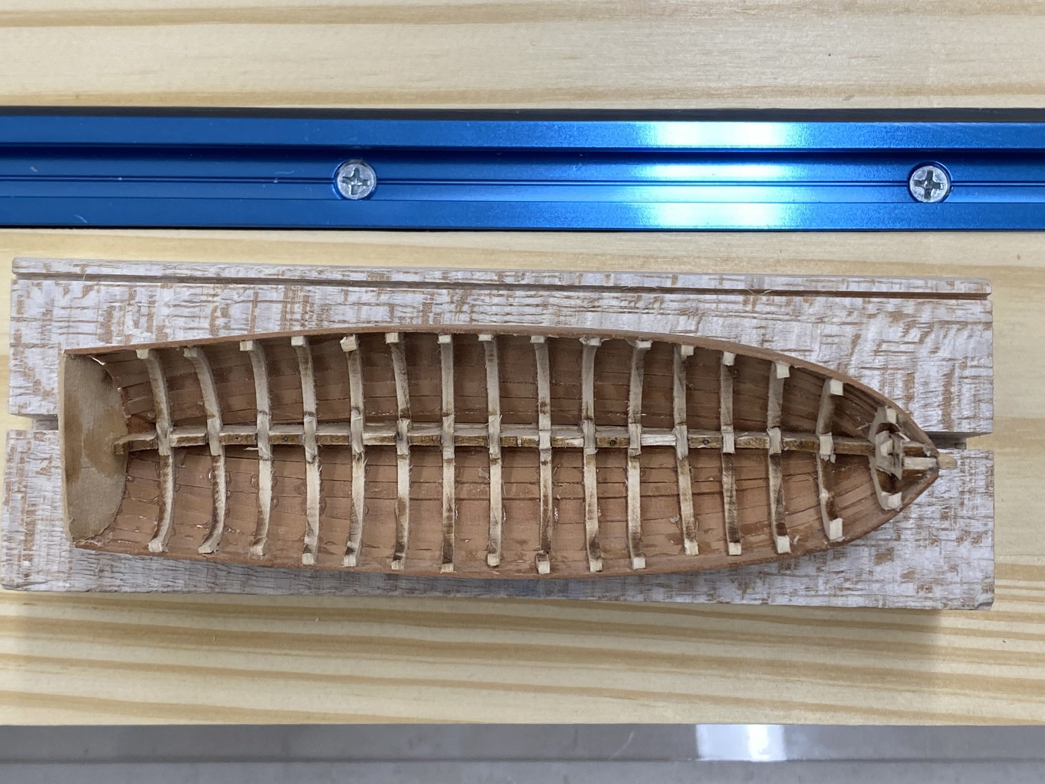
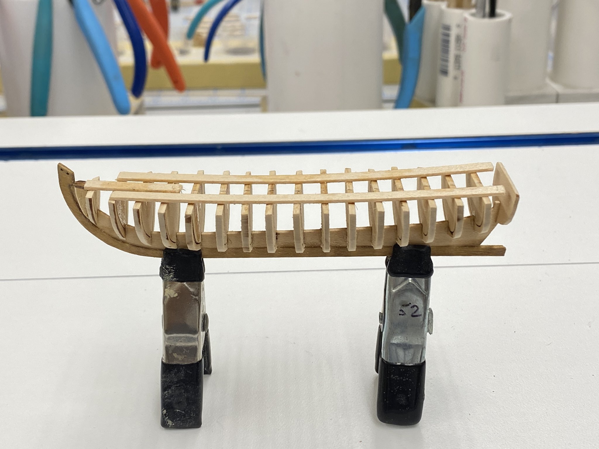
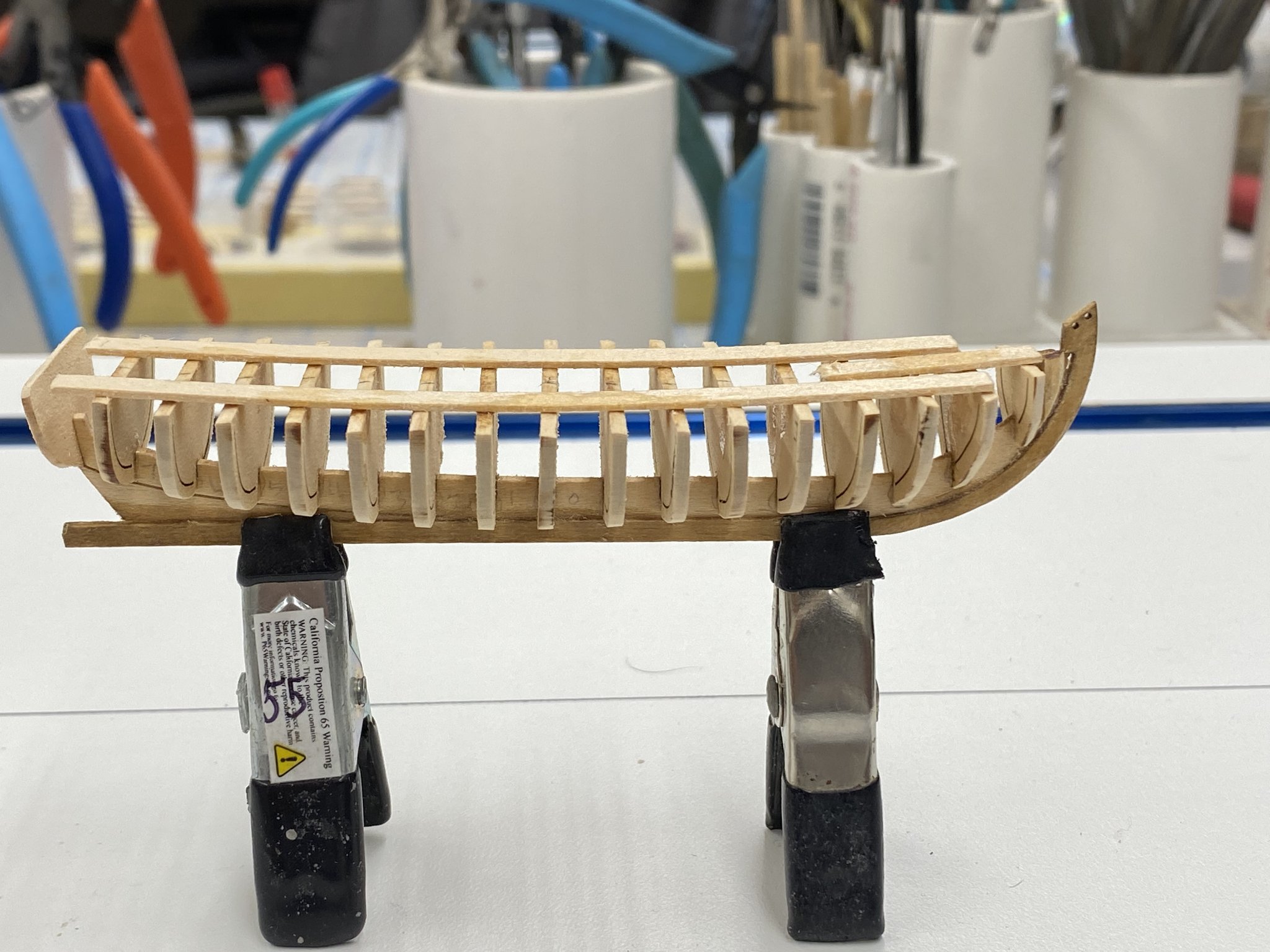
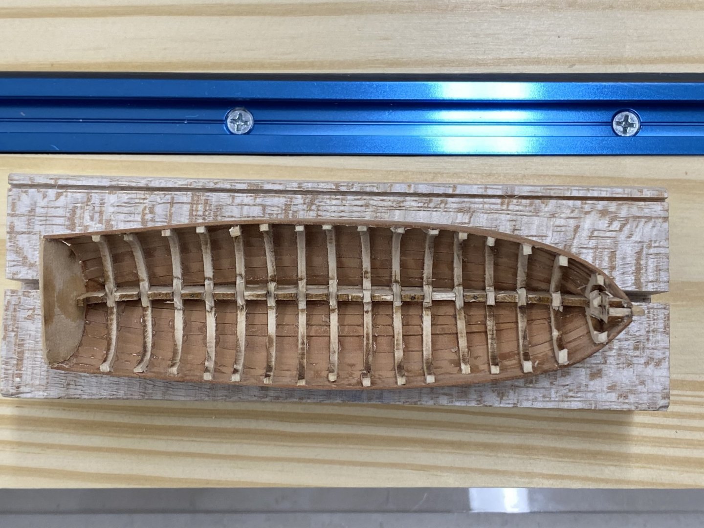
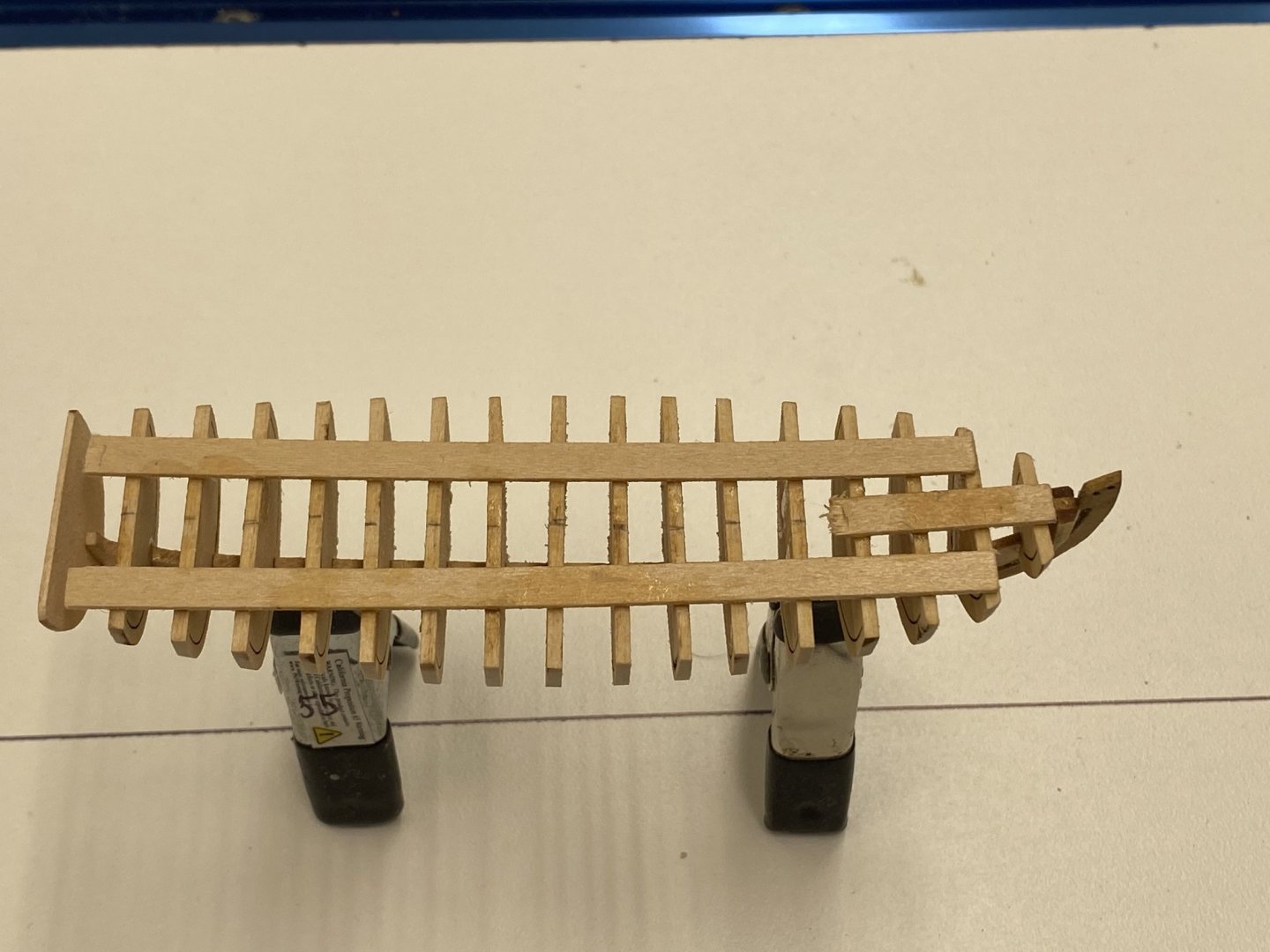
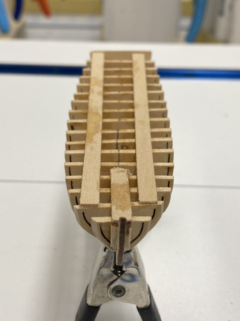
I got the longboat bulkheads secured and have faired the hull. Even though I used 320 grit sandpaper per the instructions I still managed to break one side of one of the ribs off. Had to resort to thin CA to fix - hopefully this will not make too big a mess of the interior. I will remove the strongbacks on the top once I get the top two rows at the gunnels completed. The hull was pretty stiff with them - I would not have wanted to try and fair the hull without them in place. I am also starting the pinnance. Even more bulkheads and with narrower spacing than on the long boat. I will have to thin out my fixture in order to get the pinnance to fit. Here is the longboat as it stands.


- 370 replies
-
- 2
-
-
- Model Shipways
- Confederacy
- (and 1 more)
-
Here are the bulkheads installed on the false keel. The transom and bow filler pieces have yet to be installed. I am considering adding a support member (a modified tongue depressor) across the top of the bulkheads before attempting to fair the longboat. I am hoping it will add some stability to the structure. I do not think it would take much to break the false keel while trying to fair the hull even using only 320 grit sandpaper as suggested in the instructions. Since the transom is only 1/32" thick that will not go on until the hull is faired.

-
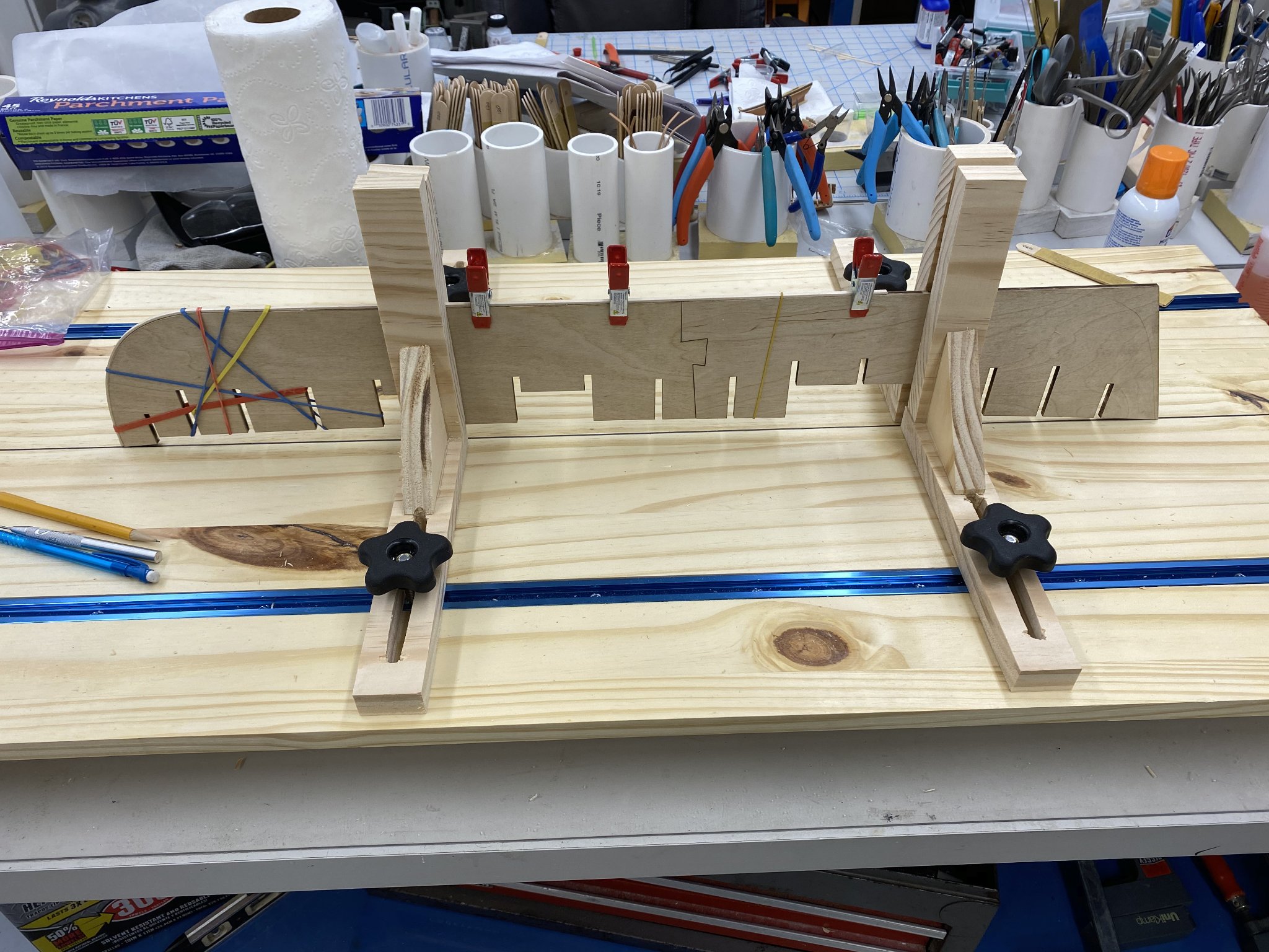
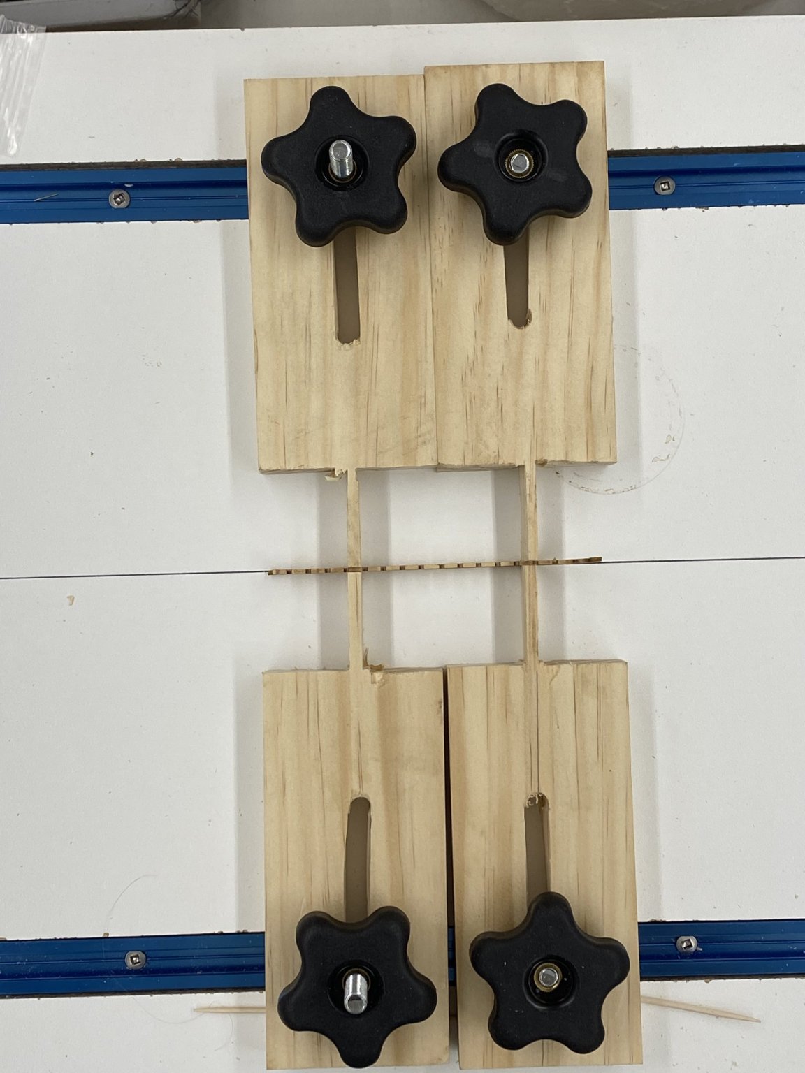
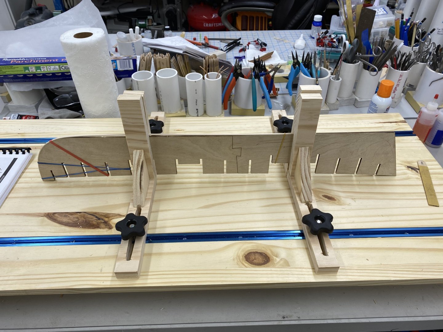
Since I have the build board I built for the Confederacy I decided to try it out on the longboat. I had to create ma set of "fixtures" for the t-Track to hold the false keel assembly in place. Since there isn't much meat on the keel itself and not wanting to stress the keel/false keel joint (it is after all only about 1/32" wide) I decided to design the fixture to hold between the bulkheads. Although pretty crude looking here is what I came up with. The toothpick you see are needed to keep the inboard ends of the fixtures on the build board. When tightening the knob they tend to lift off the board. I guess the T-Track and board are not exactly aligned. I had to cut the groove for the T-Track by repeatedly passing the board over the table saw moving it a bit each time. That does not produce as smooth a groove as a dado blade would (but THAT is another story). Here is a shot that better shows how the false keel is supported in the fixture. Now to add the bulkheads. Hopefully having the false keel held steady will make getting them properly aligned easier - probably still not easy, just easier.


- 370 replies
-
- 1
-
-
- Model Shipways
- Confederacy
- (and 1 more)
-
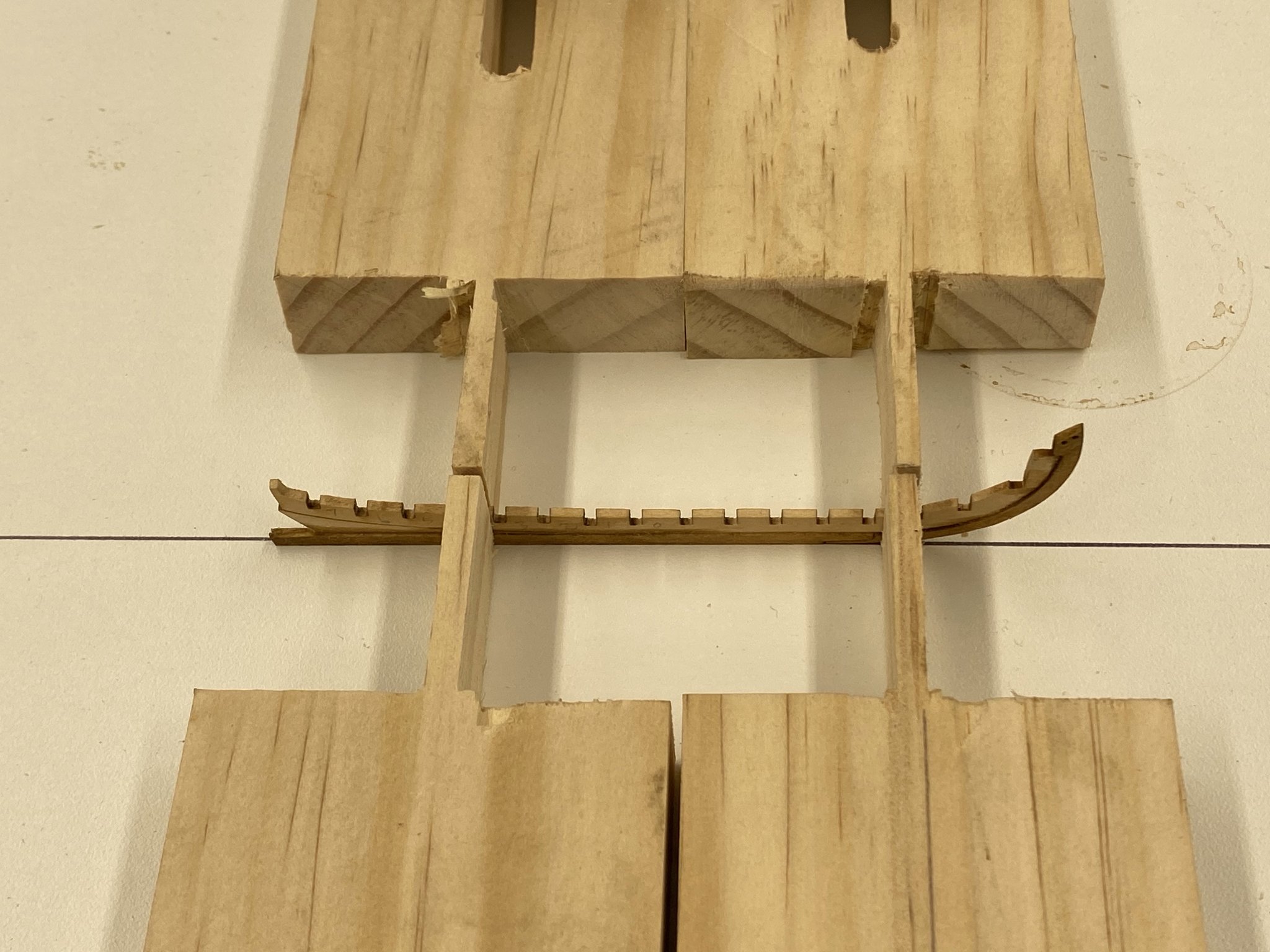
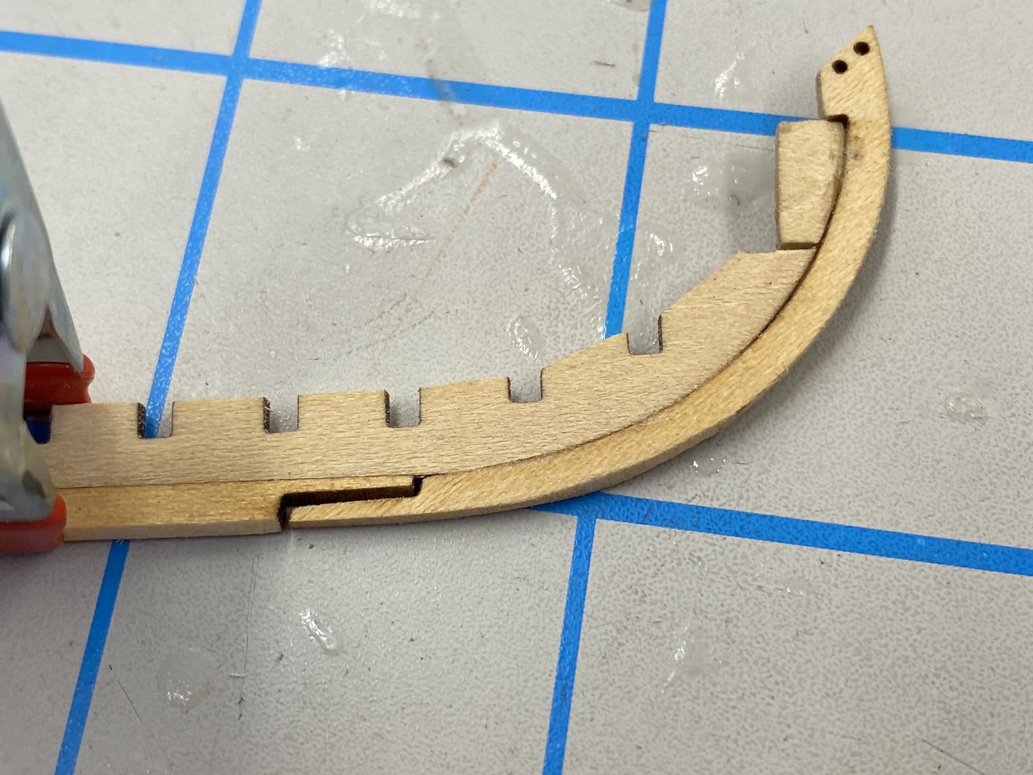
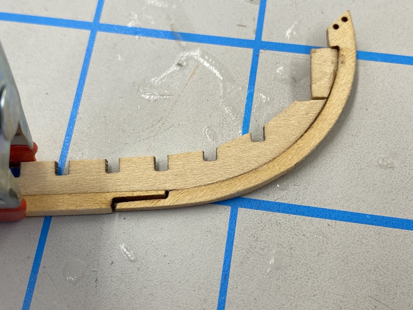
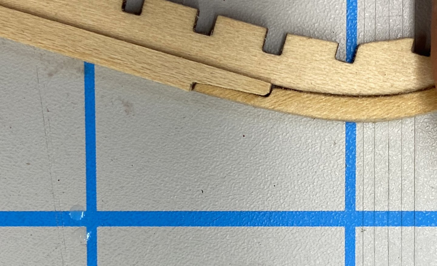
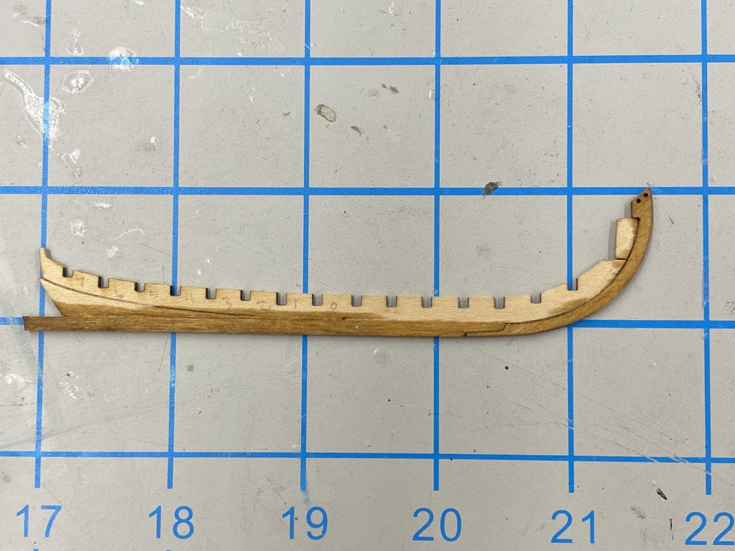
I am still waiting for the timbering set from The Lumberyard so have decided to start building the ship's boats, starting with the longboat. I started (per the instructions) by cutting the false keel, stem and keel from the carrier sheet. Interestingly, there are two each of the stem and keel on the carrier sheet - although no mention of this in the instructions. After taking off the laser char and sanding the rabbit into the false keel I started to assemble the stem, false keel and keel. The scarf junction did not have sufficient "meat" on the two pieces. There was almost 1/32" vertical gap between the two pieces - picture below. The fit was nearly the same no matter which versions of the keel/stem I used. You can also see in the picture that I broke the false keel just where bulkhead "H" would be installed. Since this is also where the bow filler pieces go I am hoping this will not become an issue. Since the keel section is straight I decided to fabricate a new piece with more "meat" at the scarf joint. I cut a piece from the carrier sheet near where the keel pieces were located and created a replacement piece. I came out pretty well IMHO. I decided to follow the instructions and stain the keel Minwax Golden Oak. So here is the false keel/stem/keel assembly after assembly and staining. When the stain dries I am going to give the exposed part of the keel/stem a coat of Wipe-On-Poly before adding the bulkheads to the false keel. Hopefully this will help protect the stem/keel during further work.
- 370 replies
-
- 3
-
-
- Model Shipways
- Confederacy
- (and 1 more)
-
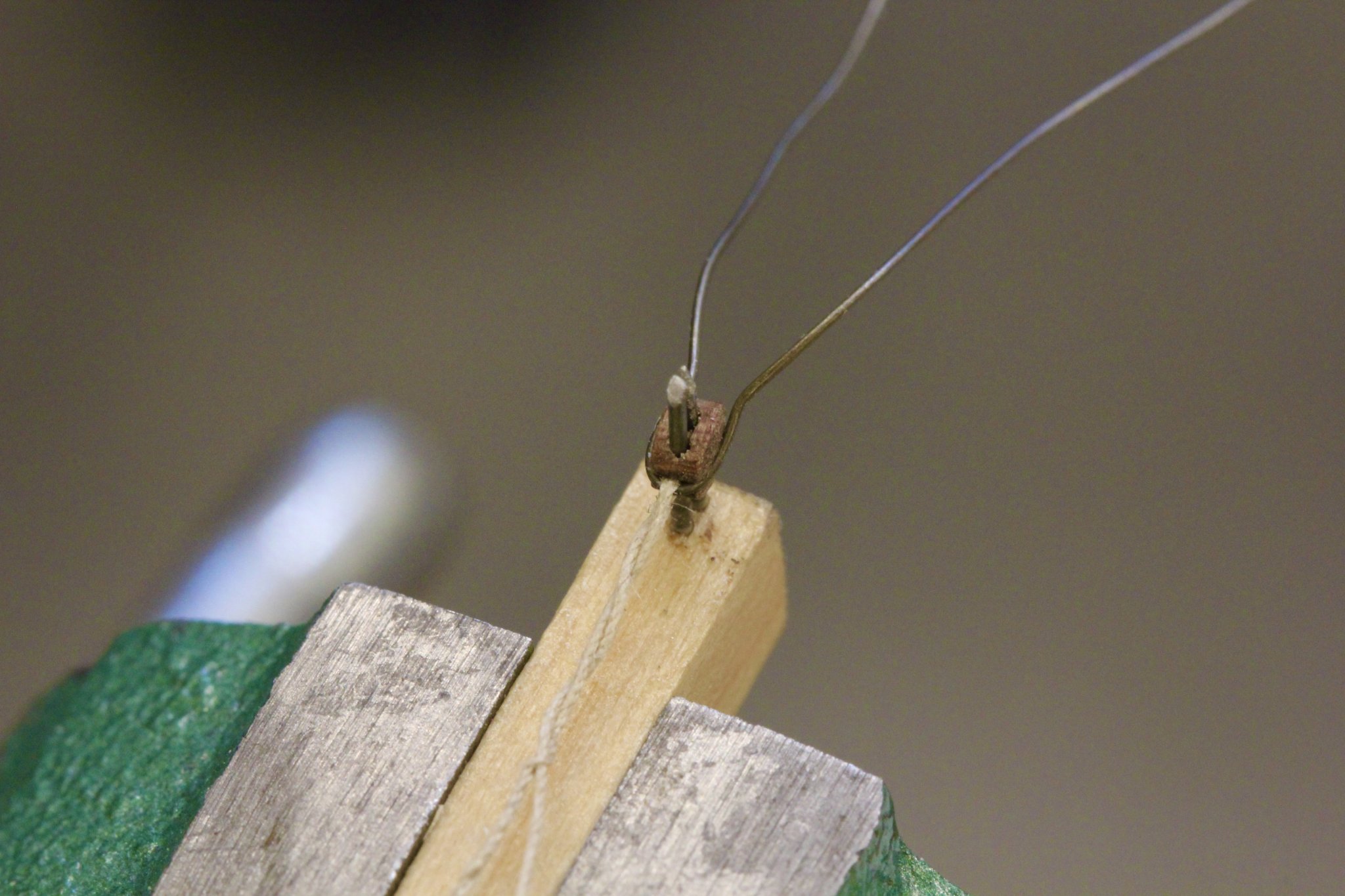
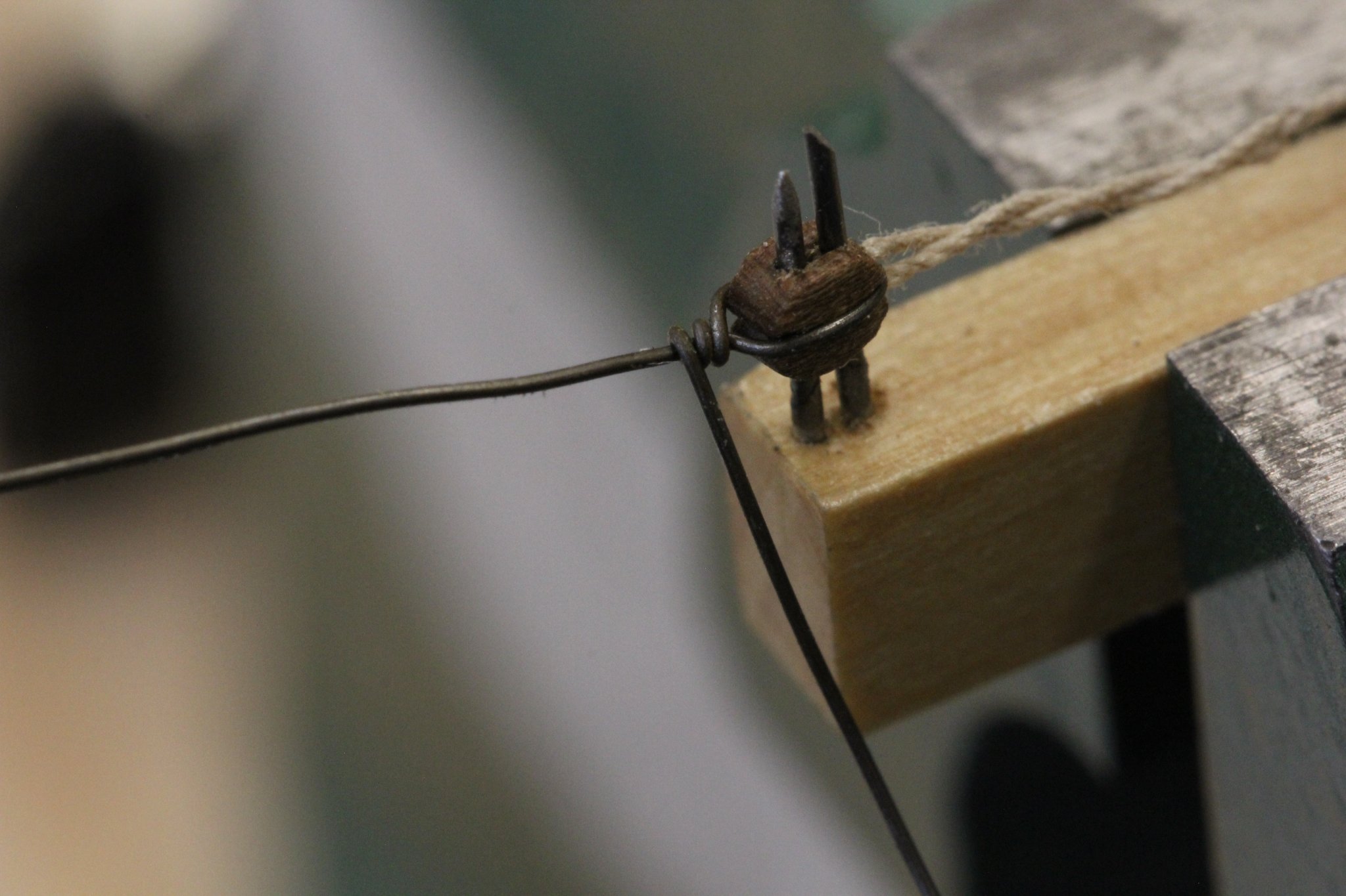
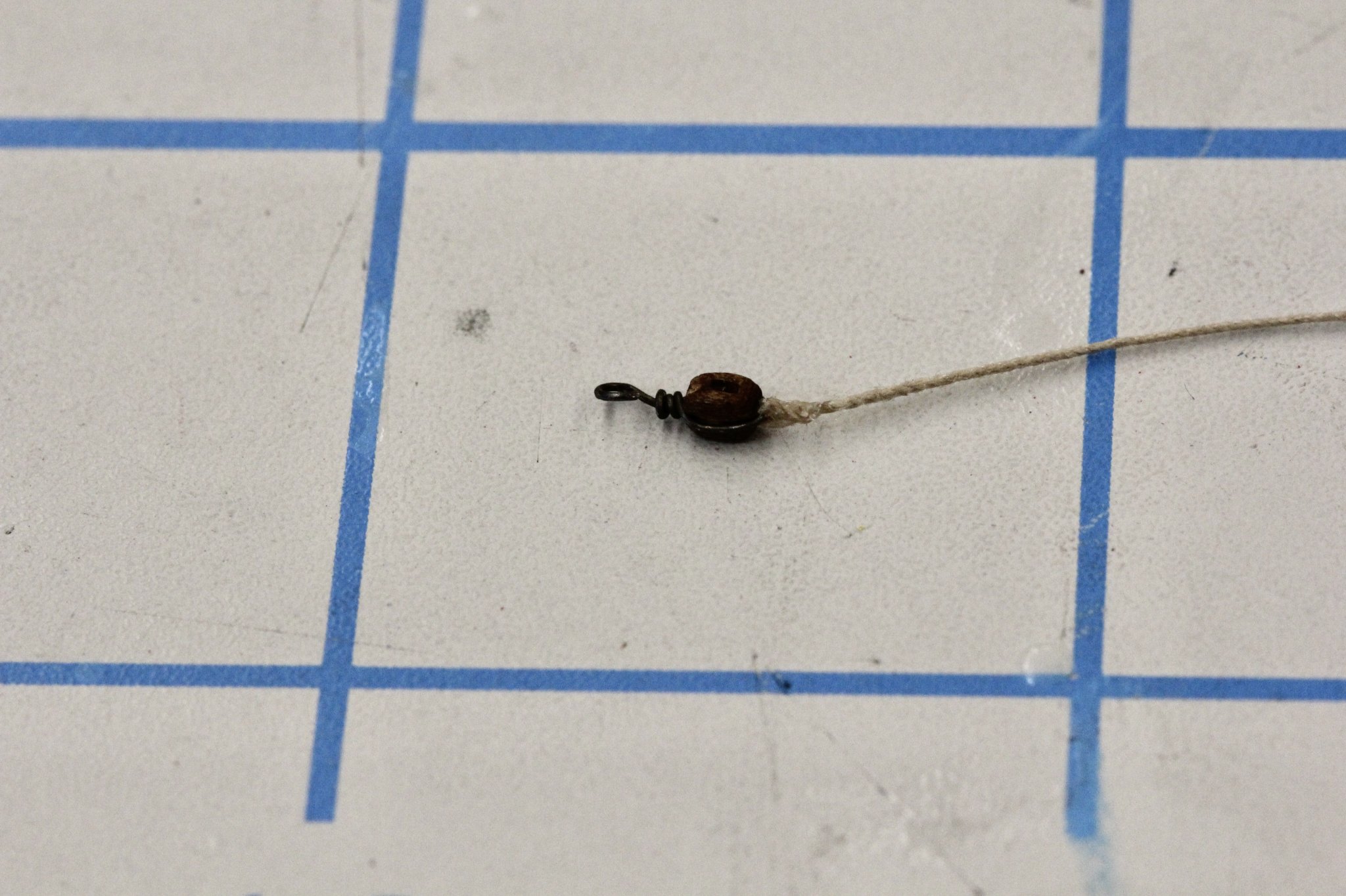
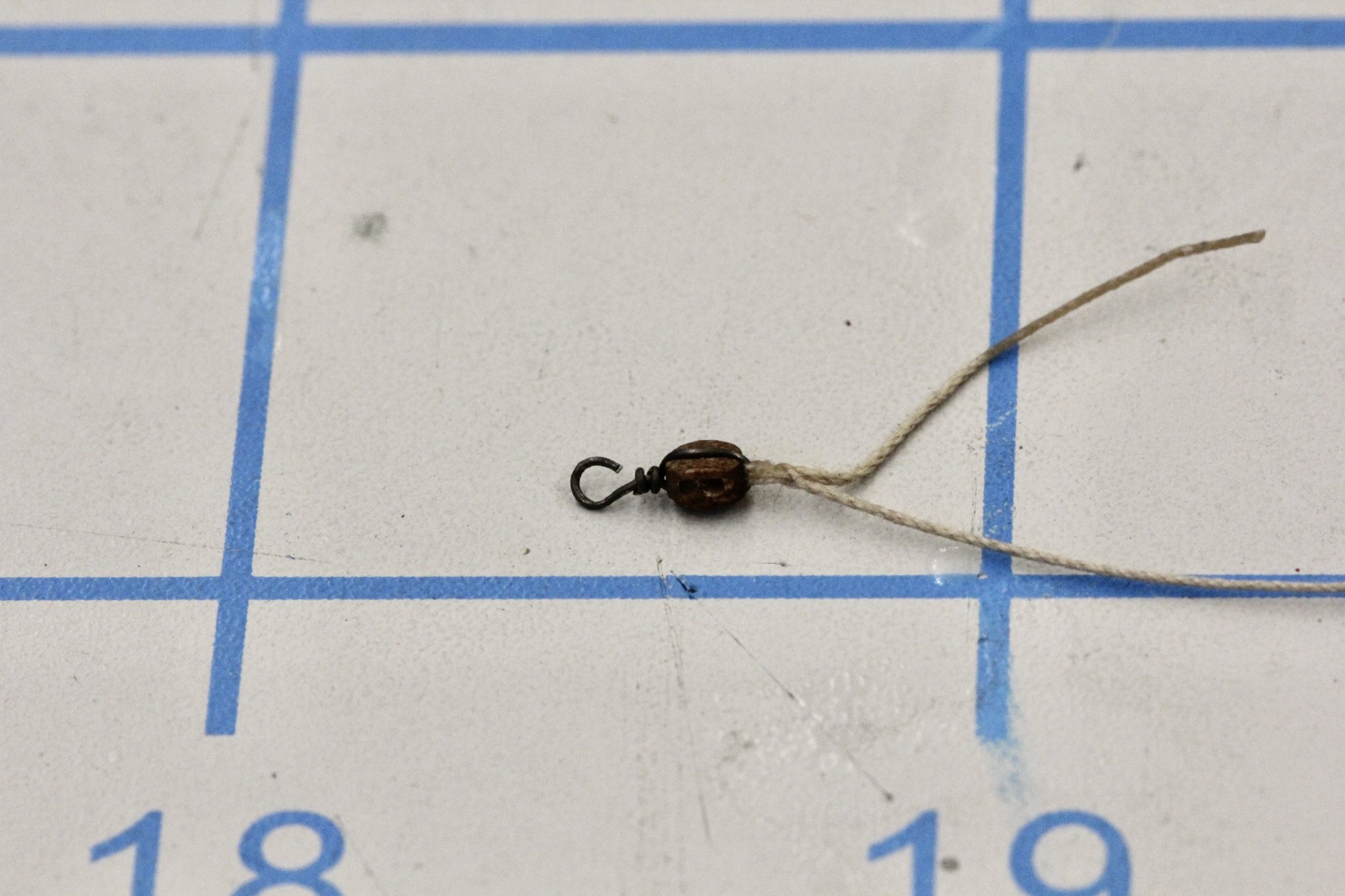
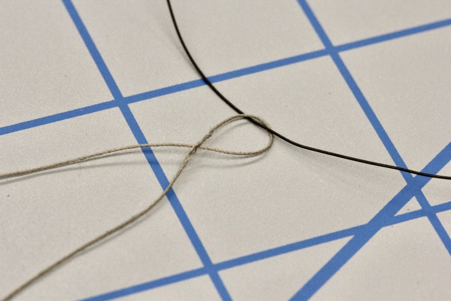
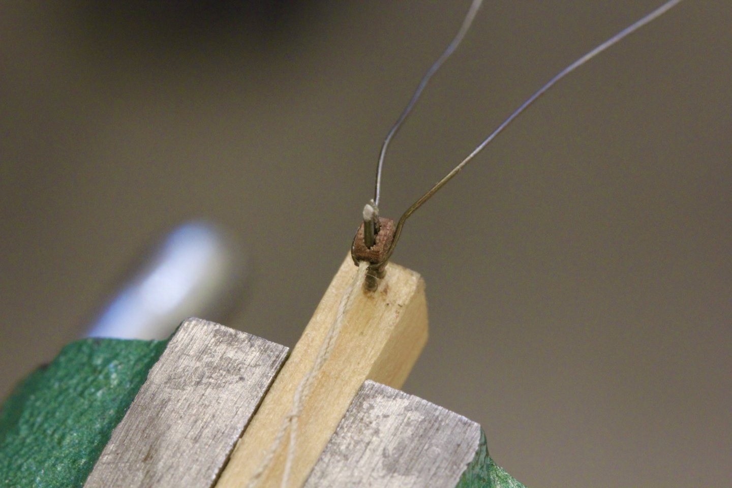
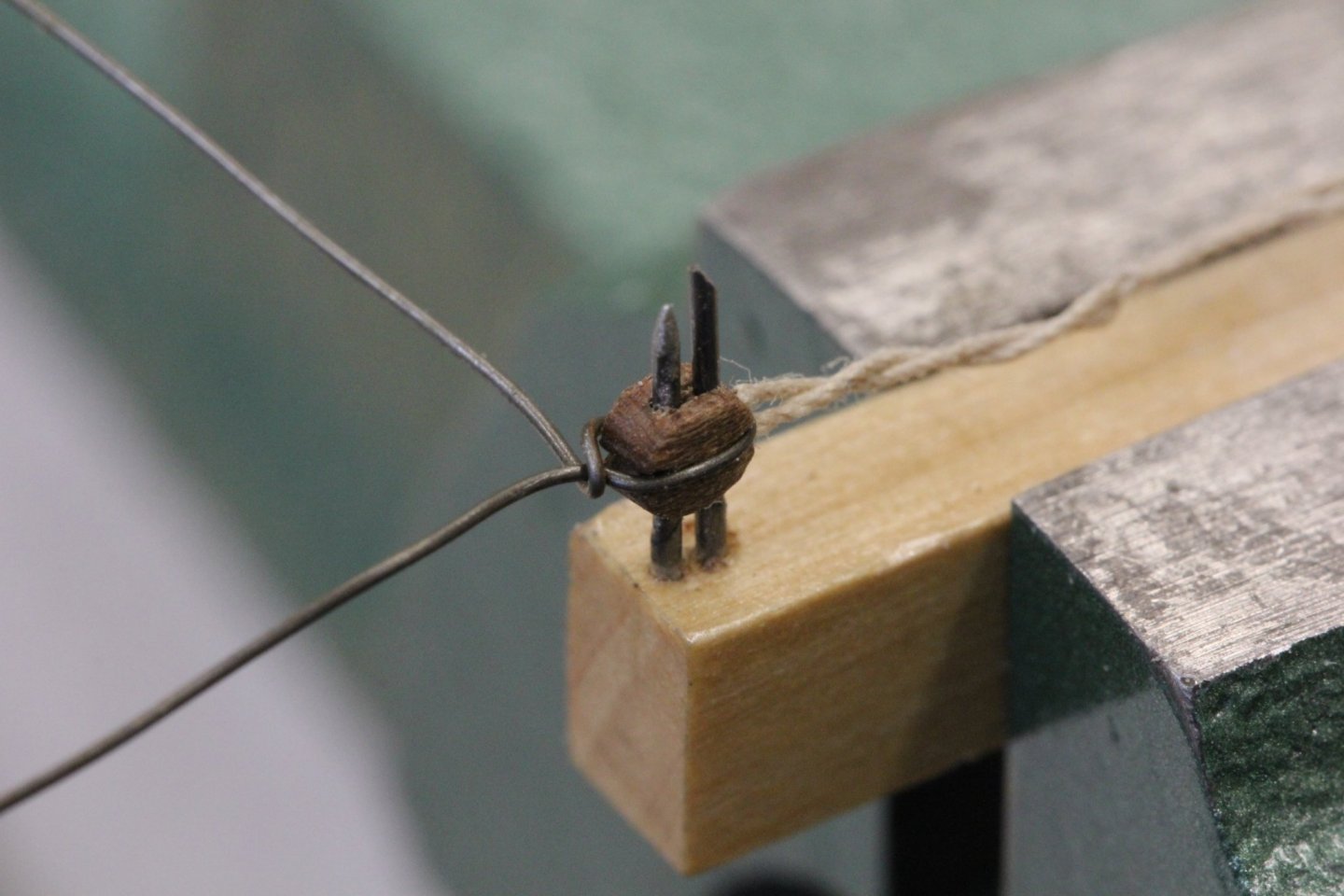
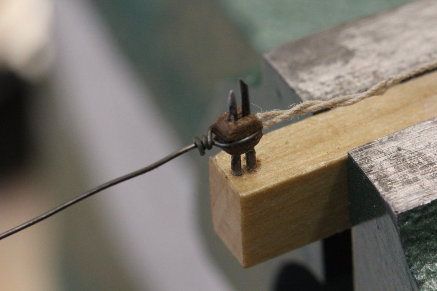
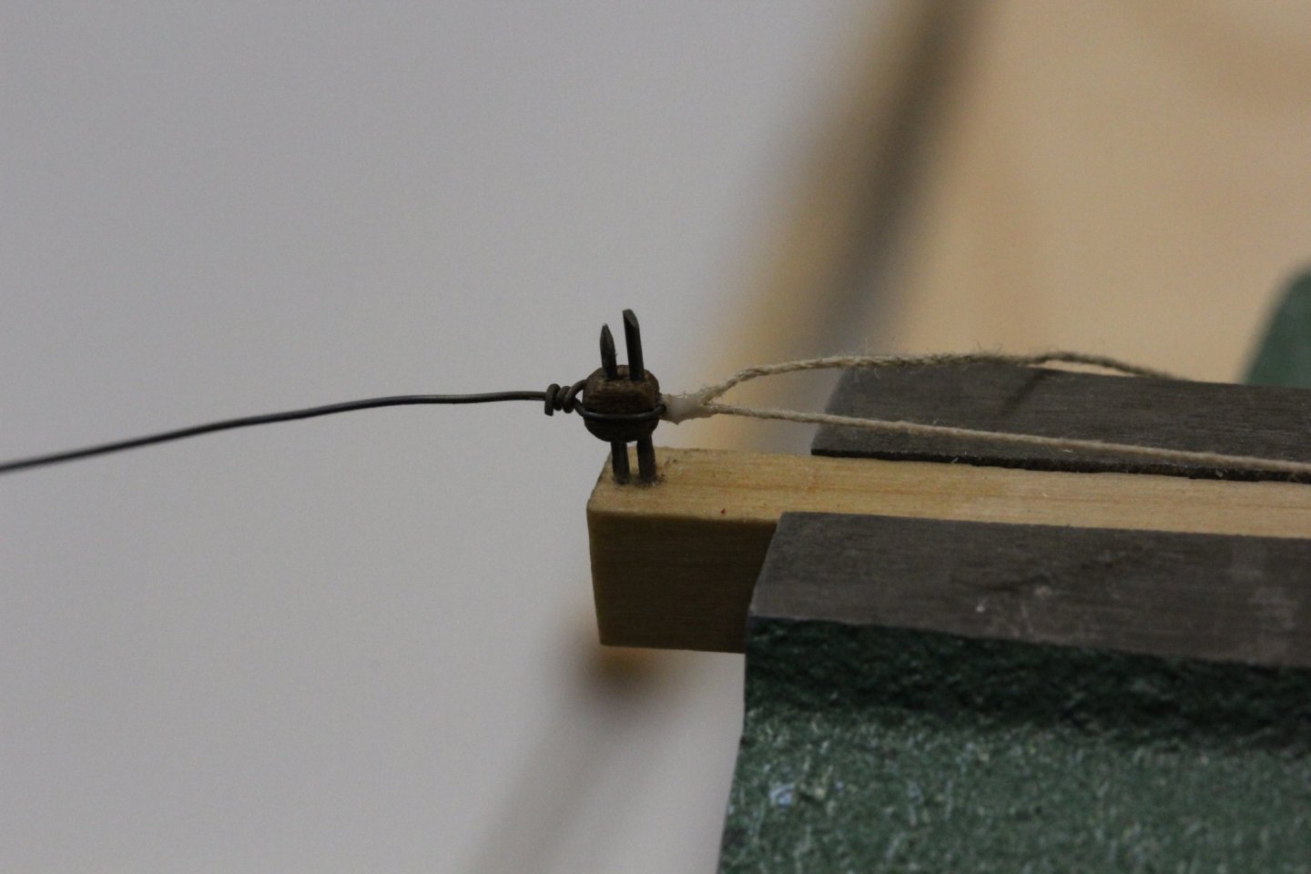
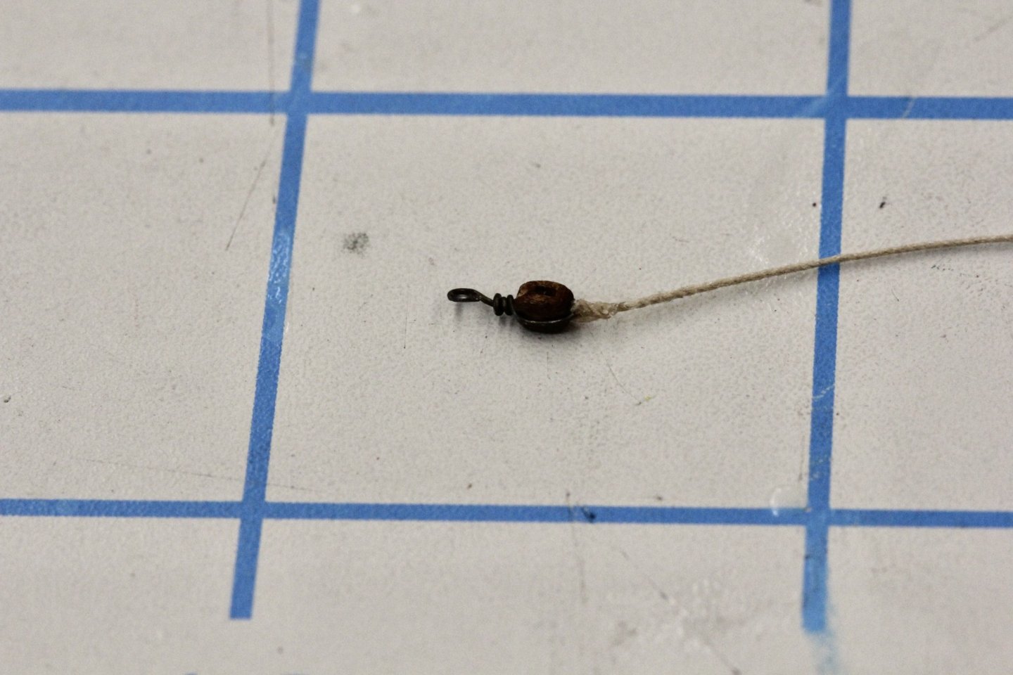
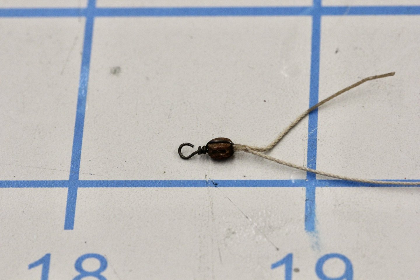
Since Model Expo is taking their time filling my order for their 2.5mm single blocks I have been working through the 20 I have making the part of the gun tackle with the line attached. Since I will have to do this 60+ times I thought I would document my procedure here on the off chance those viewing this build log might find it useful someday. I previously showed the photo below which shows the jig I created to hold the 2.5mm blocks. As I mentioned previously the wire is .020 piano wire and the block holes are drilled out with a #76 drill before putting the block on the jig. I am using Syren .008" tan line for the gun tackle so I cut a piece about 6" long, harden a bit on each end with CA and then using a awl poke a hole in the line about 1" back from one end and thread the closest hardened end through the hole. This loop will become the "eye" that holds the line to the block. I use 32 gauge annealed steel wire for the block stroping and thread a few inch piece though the eye in the line. Here is what that looks like. Although I did not do it (do as I say not as I do) this time I should have cinched the eye around the line before putting it on the block - not doing so can lead to dealing with twists in the eye materiel as you can see in the picture below of the wire wrapped around the block on three sides. I squeeze the wire against the block with pliers so it will engage the slots cut in the edges of the block. With the wire in this position, carefully bring one end across the other as close to the "top" of the block as possible while keeping the other end extended straight out from the block in more or less the block center (although this is hsrder than you might think). Continue to wrap the wire around the "standing end" until you have three loops then cut the wire as close to the standing part as possible (but not so close as to nick the standing part - this is the weakest part of the assembly and if it fails it will be right here - do not ask me how I know). Now close up the eye in the becket line (if not done before the wire was wrapped around the block) and seize with a drop of white glue. Remove from jig when glue has dried sufficiently, form hook in the standing end (and cut off excess) and trim line. It may be necessary to add some more white glue to the line, spreading it around the "seizing" with you figures to glue down any arrant ends created by cutting off the excess. Now do this 60+ more times and then 60+ times without the line and you will have the makings of the cannon tackle.


- 370 replies
-
- 3
-
-
- Model Shipways
- Confederacy
- (and 1 more)
-
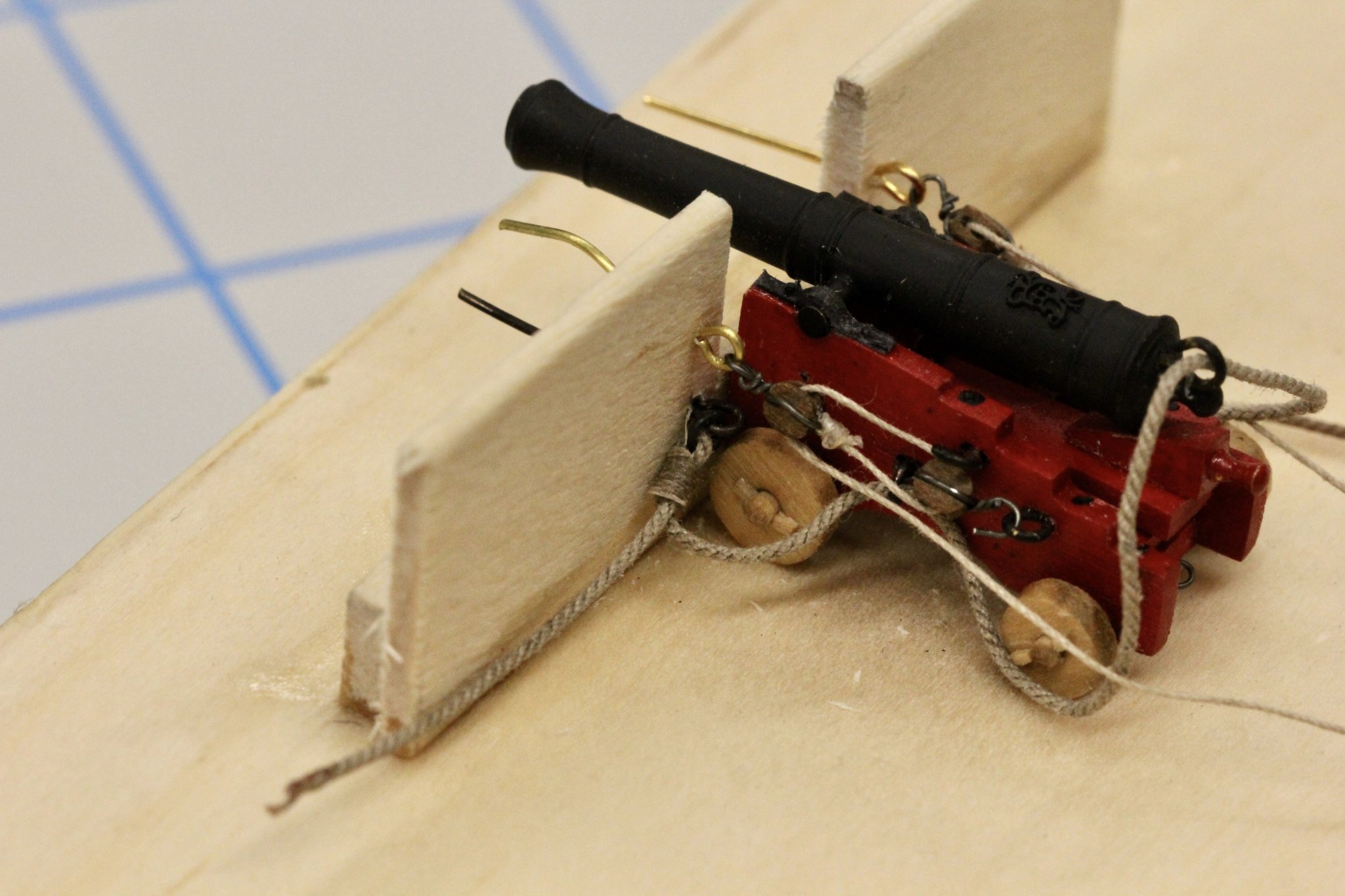
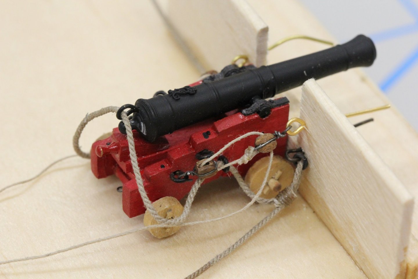
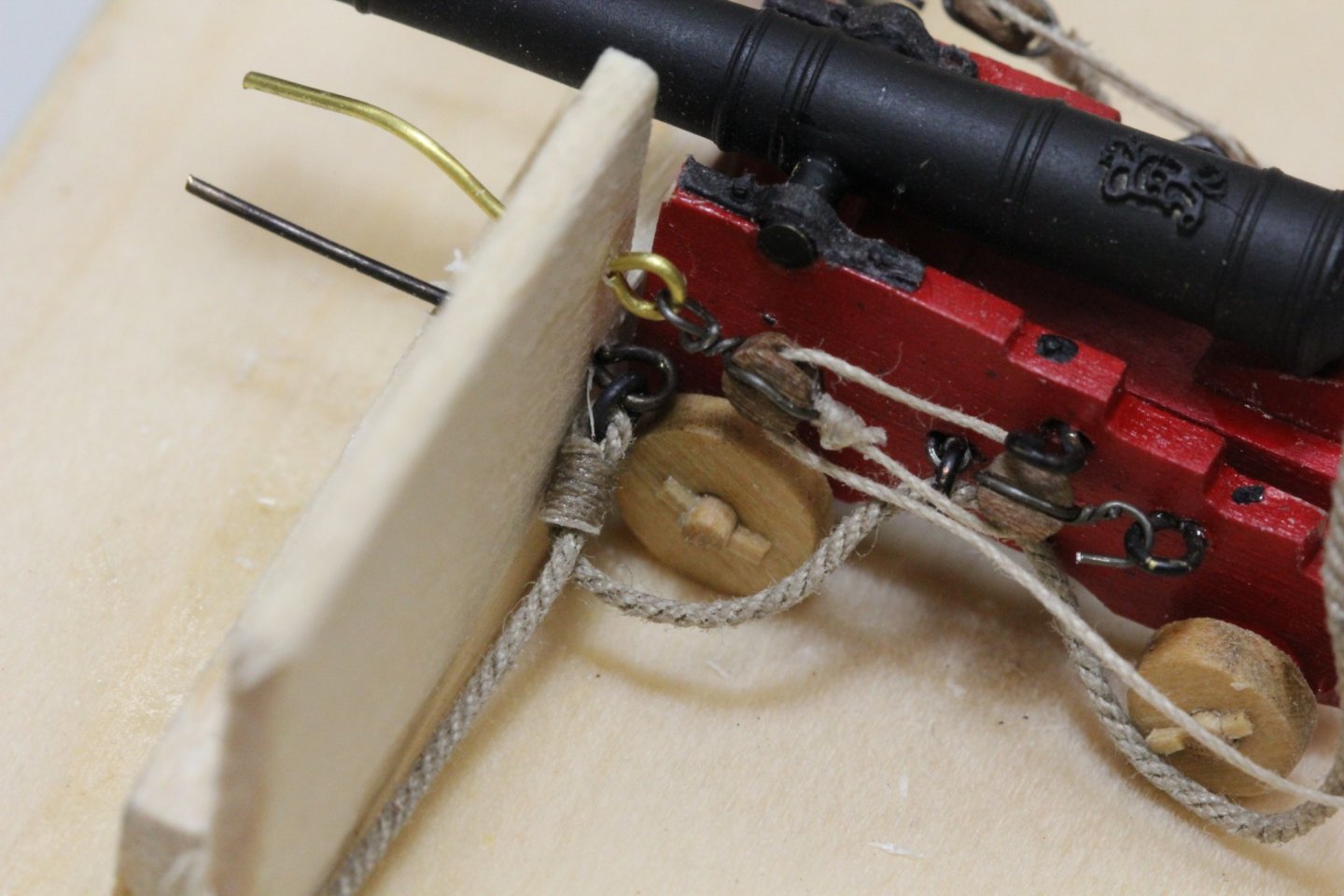
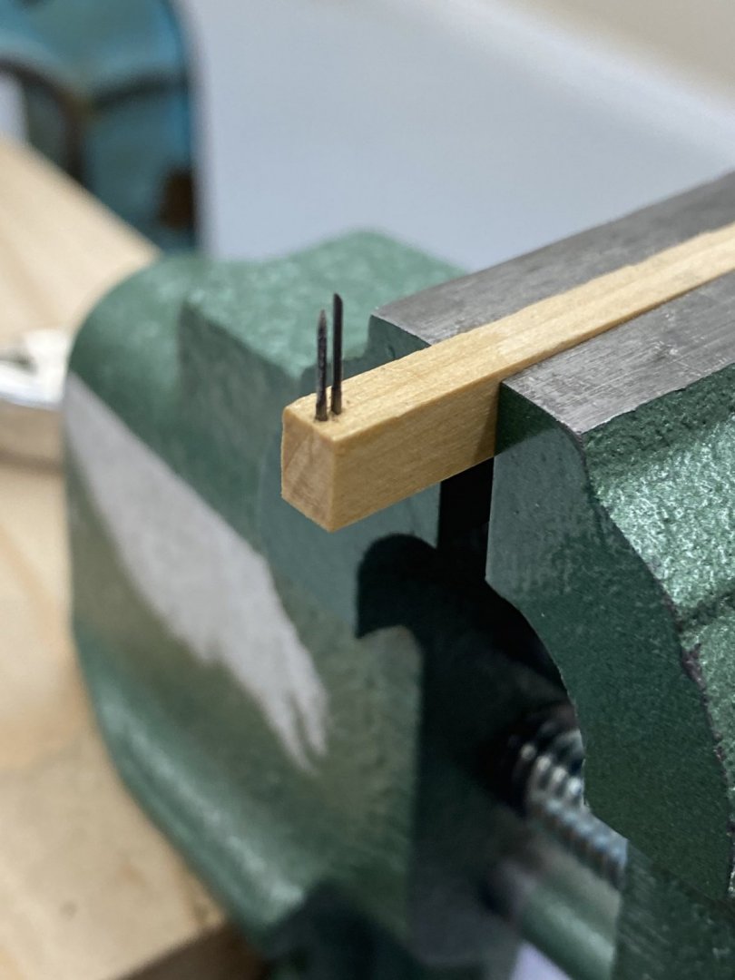
After seeing Bossman's very nice gun pictures I decided I had better set up a "test stand" to see what the tackle I contemplated would look like, and more importantly that there would be enough room for the tackle to "fit". I tried several combinations of blocks but finally decided to use the Model Expo "Beautiful" blocks in the 2.5mm size which is just a few thousands bigger than 3/32. I found the Syren 3/32 blocks did not hold up as well as the Model Expo ones when I placed them on my "jig" for stroping. The Syren blocks tended to split. Here is my jig and with a 2.5mm block ready for stroping. The pins are .020 piano wire and I drill out the holes in the block with a #76 (.020") bit before putting it in the jig. I made up two sets of tackle and built a test stand to try out the tackle on one of my completed guns. I took the measurements off the plans and drilled holes and installed the eyebolts on the bulkwark and drilled holes to accept the eyebolts with the breeching tackle. I will admit that I am planning on using some glue to "tame" the breeching tackle line as it seems to have a mind of its own. It took more maneuvering than I liked to keep it out of the way. In any event here is what my test bed looks like with the cannon installed. And a close-up of the tackle. I am working on getting the becket attachment to a sailor-like appearance. After 50 or 60 more I should have it "down" for the last few.


- 370 replies
-
- 4
-
-

-
- Model Shipways
- Confederacy
- (and 1 more)
-
Bossman - no I had not thought of that solution. I can see from your photo that 1/8" would be too big and even with 3/32 there is not much room between the two blocks in the tackle. I have several ideas for stroping the blocks with 30 or 32 gauge annealed steel wire but think this solution is more elegant although I have some doubts I can make hooks that small reliably.
-
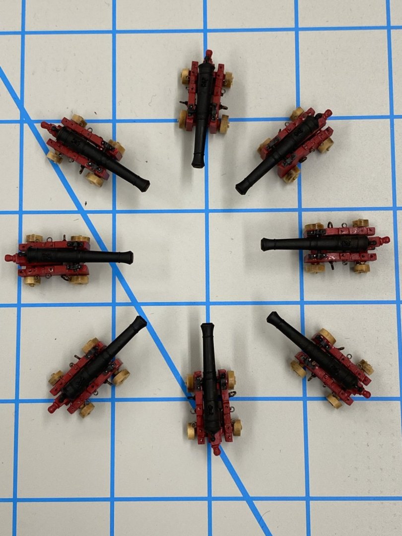
All eight of the 6-pounders are complete and in a storage container. Now on to trying to figure out the gun tackles. The kit provides 3/32" blocks but I am considering going to 1/8" for the 12 pounders. I am also trying to decide if I will use the Syren blocks or give the newly available pearwood blocks from Model Expo a try. I am not a big fan of trying to make very small wire hooks and glue them into wooden blocks as called for in the instructions. I have not had good experiences keeping the hooks in the blocks as there is very little contact area if the top hole (sheave) is drilled out to accept the line. The blocks shown in the instructions have only a single hole which is in the center which provides more contact area for gluing in the hook but sacrifices some accuracy as the real blocks would have had a real sheave for the line to move over.
- 370 replies
-
- 2
-
-
- Model Shipways
- Confederacy
- (and 1 more)
-
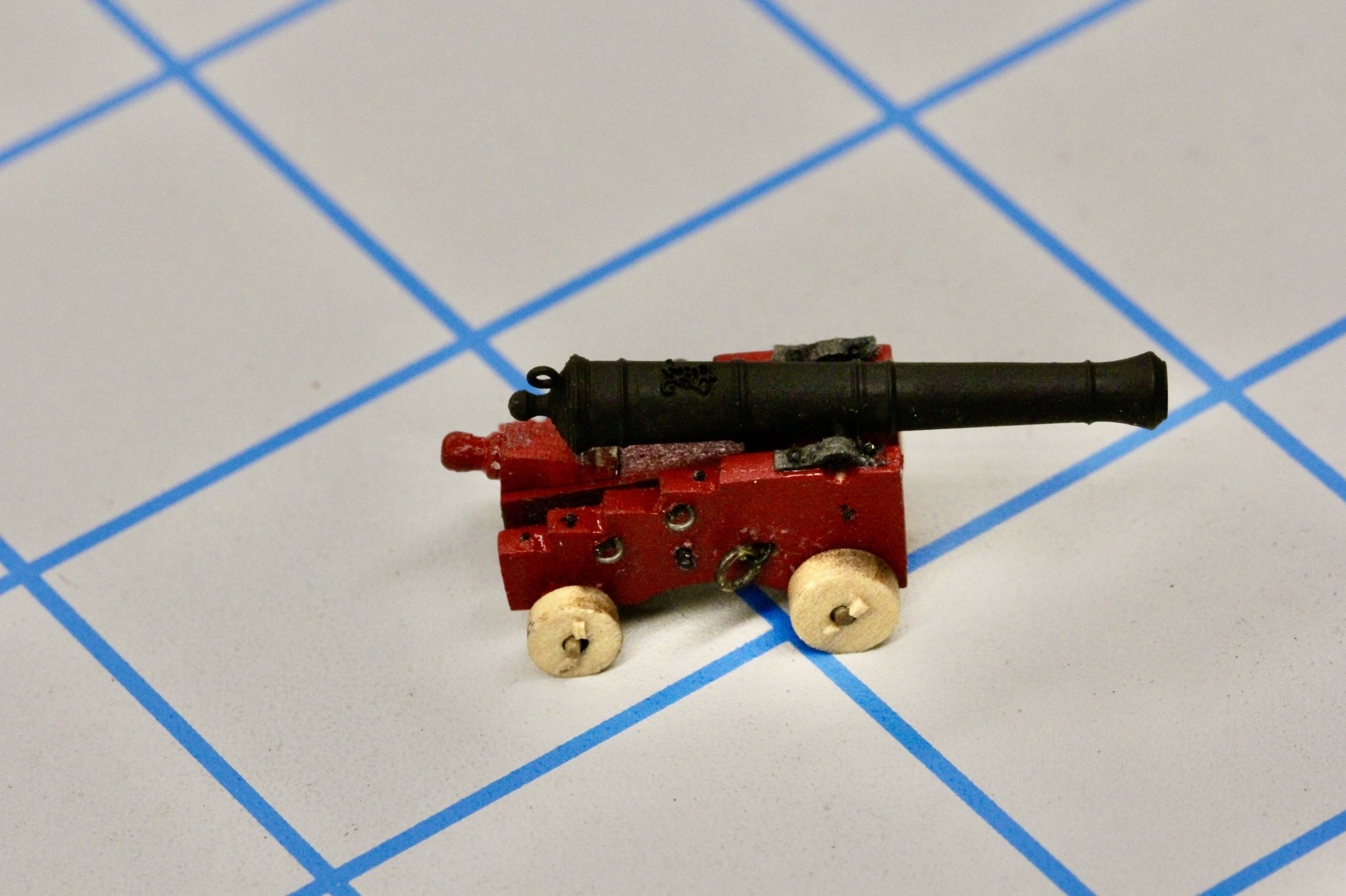
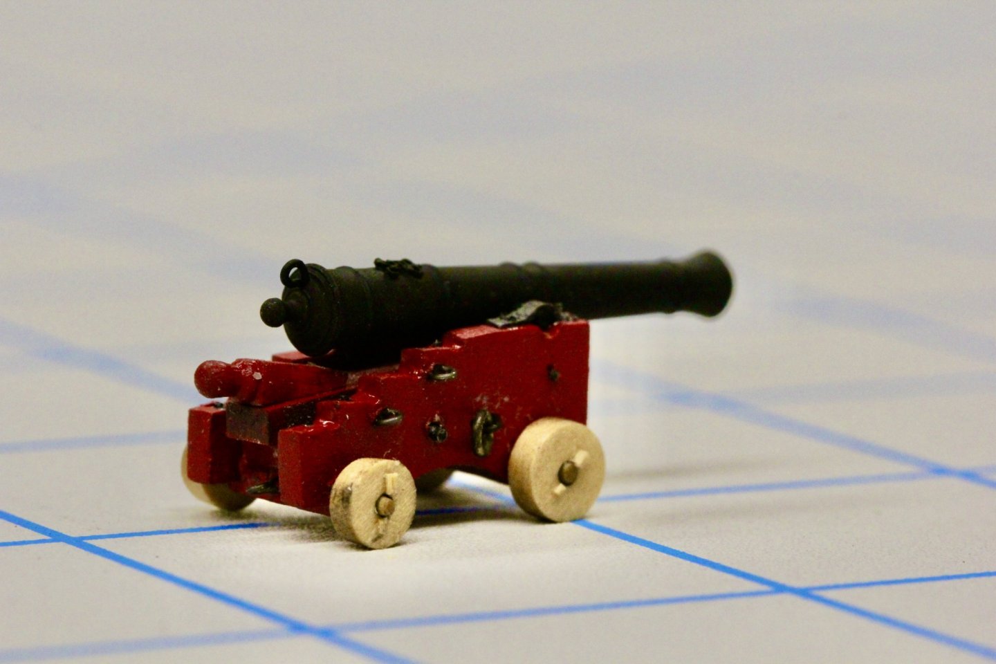
I got one of the 6-pounders complete except for the breeching tackle so here are two shots made with my digital SLR instead of the iPhone. I have everything on the other seven except for the trunnion cap and associated "bolts" so should have them all completed tomorrow or Sunday at the latest. Then the breeching tackle and I'll start on the out-haul tackles (all 70 or so of them).

- 370 replies
-
- 4
-
-
- Model Shipways
- Confederacy
- (and 1 more)
-
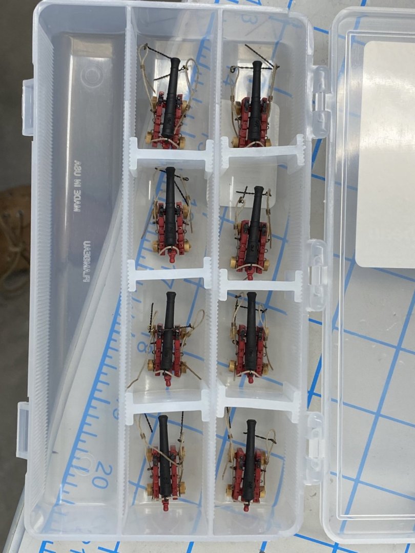
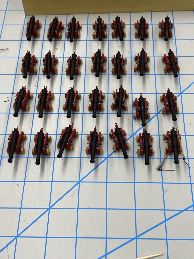
Thank you Jean-Paul I got all the 12-pounders touched up and the breeching tackle rigged so I have put them in a storage box to keep the saw dust (while will be coming shortly) out. I rigged the breeching rope under the rear wheels so that gravity will help to shape the rigging line while they sit in storage. Now on to the 6 pounders (only 8 of these worst case).
- 370 replies
-
- 3
-
-
- Model Shipways
- Confederacy
- (and 1 more)
-
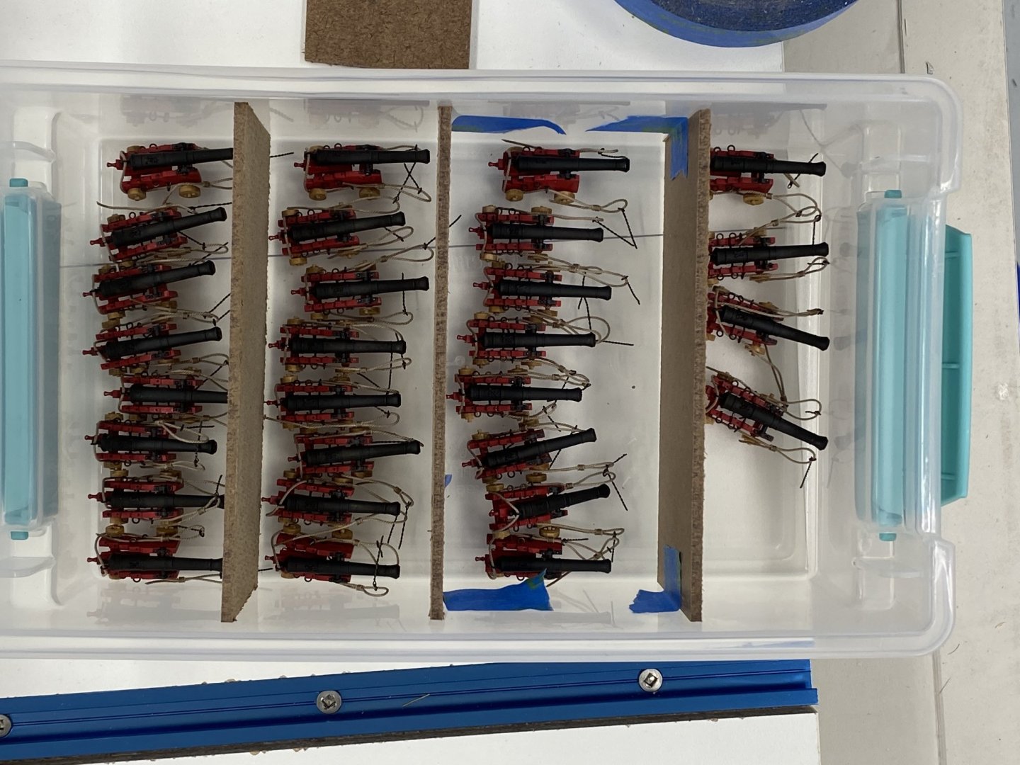
All 28 12 pounders now have the trunnion caps and simulated bolt heads installed. I need to touch up the bolt heads (and some of the caps) with flat black but should get any red touch-up done first. So I have taken all the pieces of the 6 pounder carriages out of their carrier sheets and am removing the laser char in preparation for painting them and while I have the red paint available I will touch up the 12 pounder carriages too. So here are the 28 12 pounders waiting for touch-up and then the breeching tackle before going into "cold storage" until later.
- 370 replies
-
- 2
-
-
- Model Shipways
- Confederacy
- (and 1 more)