.jpg.7c32e8ae1fa7512b33601c57a0006559.jpg)
shauer
-
Posts
85 -
Joined
-
Last visited


-
 shauer reacted to a post in a topic:
Double Capstan Project by shauer - Portland Scale Ship Co Kit
shauer reacted to a post in a topic:
Double Capstan Project by shauer - Portland Scale Ship Co Kit
-
 Desertanimal reacted to a post in a topic:
Double Capstan Project by shauer - Portland Scale Ship Co Kit
Desertanimal reacted to a post in a topic:
Double Capstan Project by shauer - Portland Scale Ship Co Kit
-
Nunnehi (Don) reacted to a post in a topic:
Double Capstan Project by shauer - Portland Scale Ship Co Kit
-
shauer reacted to a post in a topic:
Double Capstan Project by shauer - Portland Scale Ship Co Kit
-
Ryland Craze reacted to a post in a topic:
Double Capstan Project by shauer - Portland Scale Ship Co Kit
-
scrubbyj427 reacted to a post in a topic:
Double Capstan Project by shauer - Portland Scale Ship Co Kit
-
scrubbyj427 reacted to a post in a topic:
Double Capstan Project by shauer - Portland Scale Ship Co Kit
-
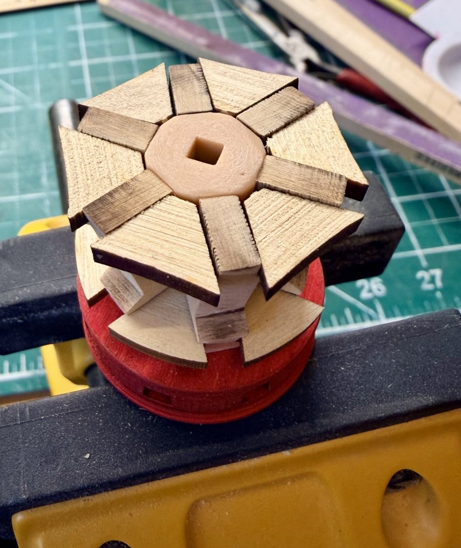
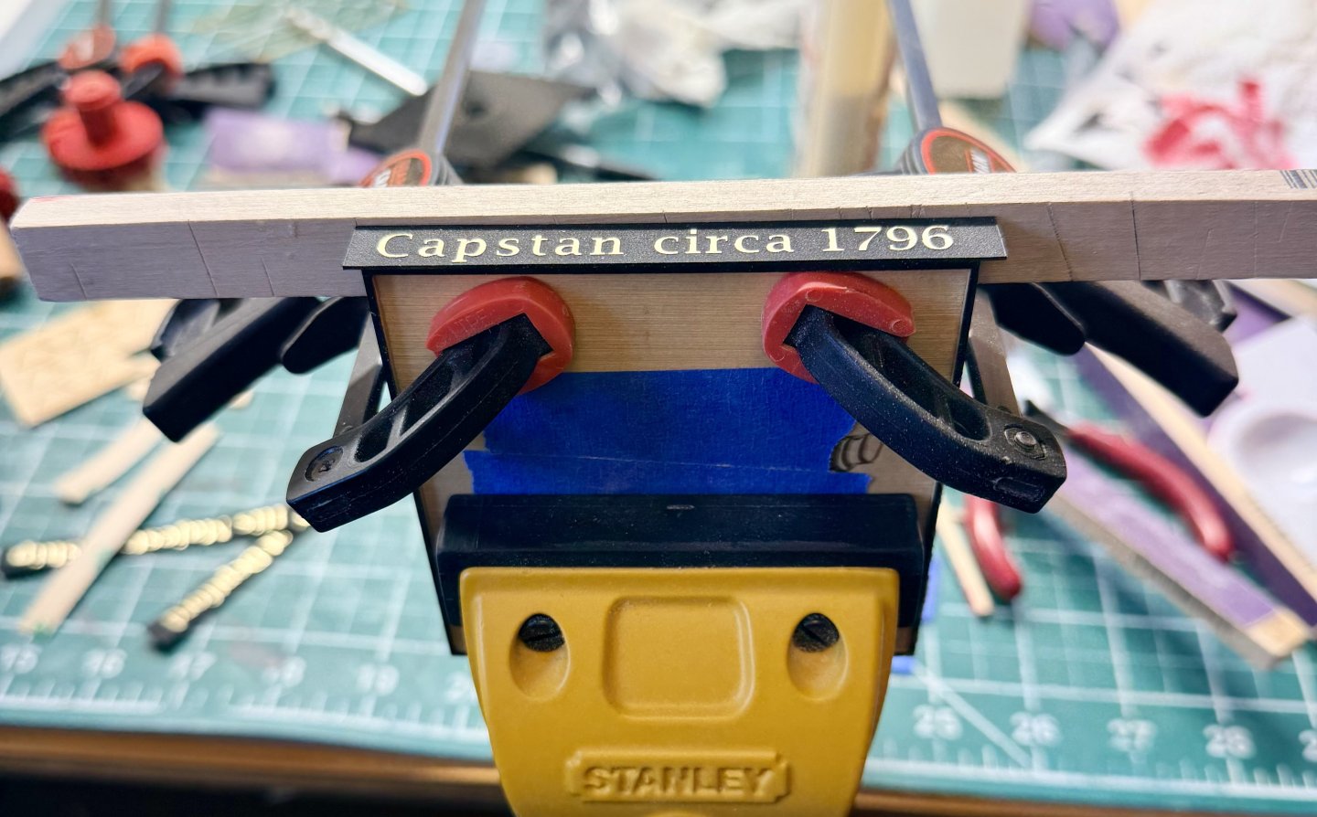
.thumb.jpg.0c4ba74a8c20632da6eafe3d432bde24.jpg) Update on work completed in the past 24 hours or so. I glued part 'C' to the underside of the ring assembly now that I have it dyed black. Still need to add the pawls. WARNING! - make sure you clamp the 1/8 inch thick base (LB-1) when attaching it to the lower stand. The 1/8 inch thick material warped pretty impressively when I glued it down with wood glue and no clamps. A rookie mistake, but I thought the material was thick enough to not warp. I was able to safely remove it (since most of it was not glued down anyway) and then do the job properly. A few in-progress pictures of installing the chocks on the lower capstan. This took some time as most of them required a little tweaking to fit tightly. I left them oversized per the instructions and then shaped them once assembled. Then repeated the whole process for the upper capstan. The whelps require a fair amount of cleaning up as the 1/4 inch thick material has a good amount of char as you would expect on the thicker material. To keep from rounding off the corners and also keep all the whelps the same shape, I stack them together and hold the stack while working them with sanding sticks. This provides enough surface area to keep the sanding stick level, and protects the corners of the whelps. And then a couple coats of really thinned down crimson paint (about the viscosity of water). Still have a couple more coats to go. Need to add the pawls to the ring, add the bolts, and the black rings to the tops of the drums. That's about it and I figure I'll be done some time later this week. Steve
Update on work completed in the past 24 hours or so. I glued part 'C' to the underside of the ring assembly now that I have it dyed black. Still need to add the pawls. WARNING! - make sure you clamp the 1/8 inch thick base (LB-1) when attaching it to the lower stand. The 1/8 inch thick material warped pretty impressively when I glued it down with wood glue and no clamps. A rookie mistake, but I thought the material was thick enough to not warp. I was able to safely remove it (since most of it was not glued down anyway) and then do the job properly. A few in-progress pictures of installing the chocks on the lower capstan. This took some time as most of them required a little tweaking to fit tightly. I left them oversized per the instructions and then shaped them once assembled. Then repeated the whole process for the upper capstan. The whelps require a fair amount of cleaning up as the 1/4 inch thick material has a good amount of char as you would expect on the thicker material. To keep from rounding off the corners and also keep all the whelps the same shape, I stack them together and hold the stack while working them with sanding sticks. This provides enough surface area to keep the sanding stick level, and protects the corners of the whelps. And then a couple coats of really thinned down crimson paint (about the viscosity of water). Still have a couple more coats to go. Need to add the pawls to the ring, add the bolts, and the black rings to the tops of the drums. That's about it and I figure I'll be done some time later this week. Steve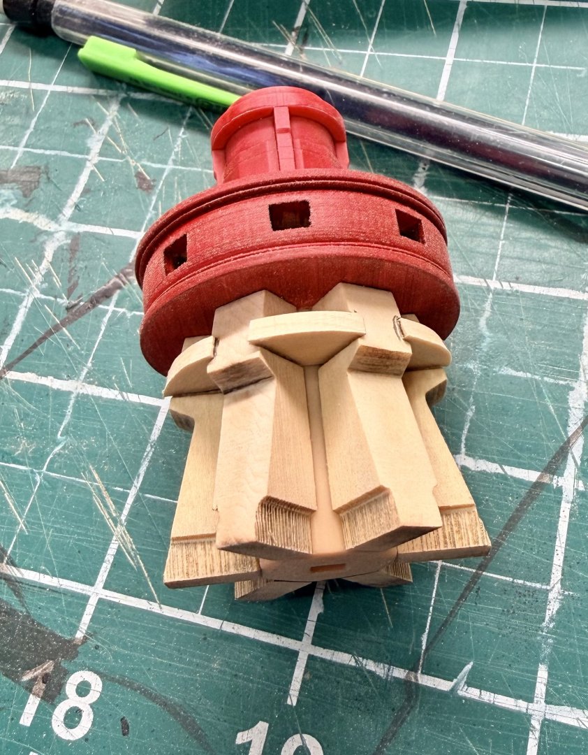


-
shauer reacted to a post in a topic:
HMS Portland 1770 by westwood - Portland Scale Ship Co. - 1:48 - 50 gun 4th rate
-
shauer reacted to a post in a topic:
HMS Portland 1770 by westwood - Portland Scale Ship Co. - 1:48 - 50 gun 4th rate
-
Ryland Craze reacted to a post in a topic:
Double Capstan Project by shauer - Portland Scale Ship Co Kit
-
Desertanimal reacted to a post in a topic:
Double Capstan Project by shauer - Portland Scale Ship Co Kit
-
Desertanimal reacted to a post in a topic:
Double Capstan Project by shauer - Portland Scale Ship Co Kit
-
TK1 reacted to a post in a topic:
Double Capstan Project by shauer - Portland Scale Ship Co Kit
-
TK1 reacted to a post in a topic:
Double Capstan Project by shauer - Portland Scale Ship Co Kit
-
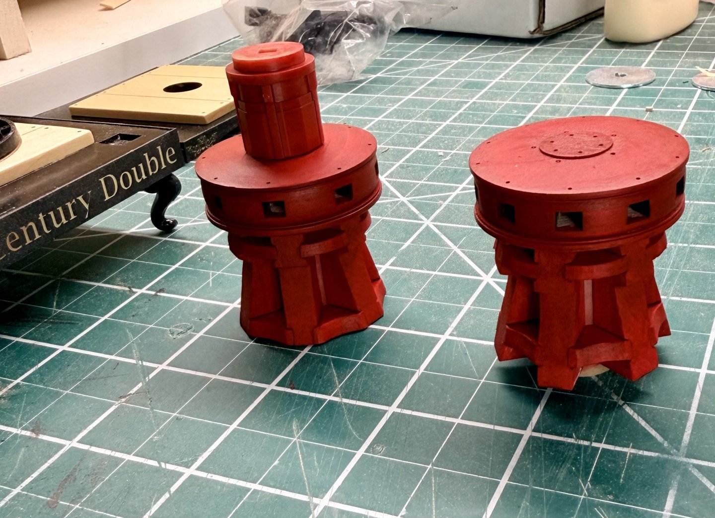
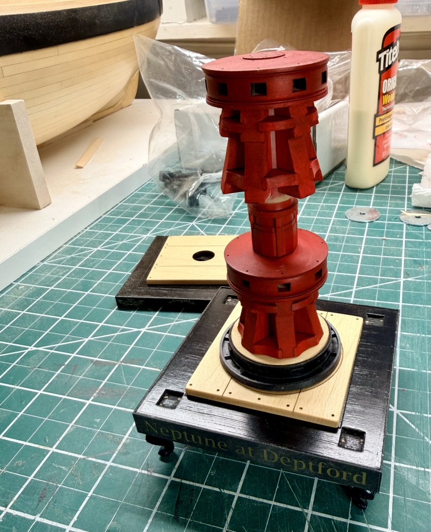
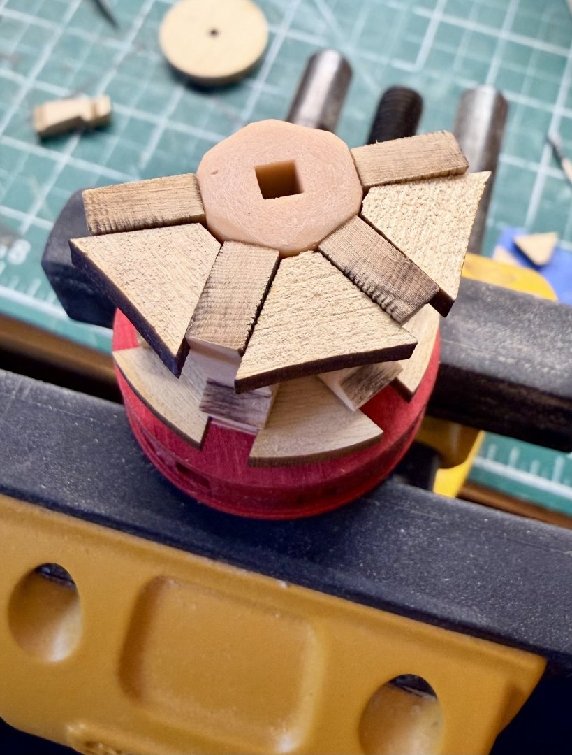
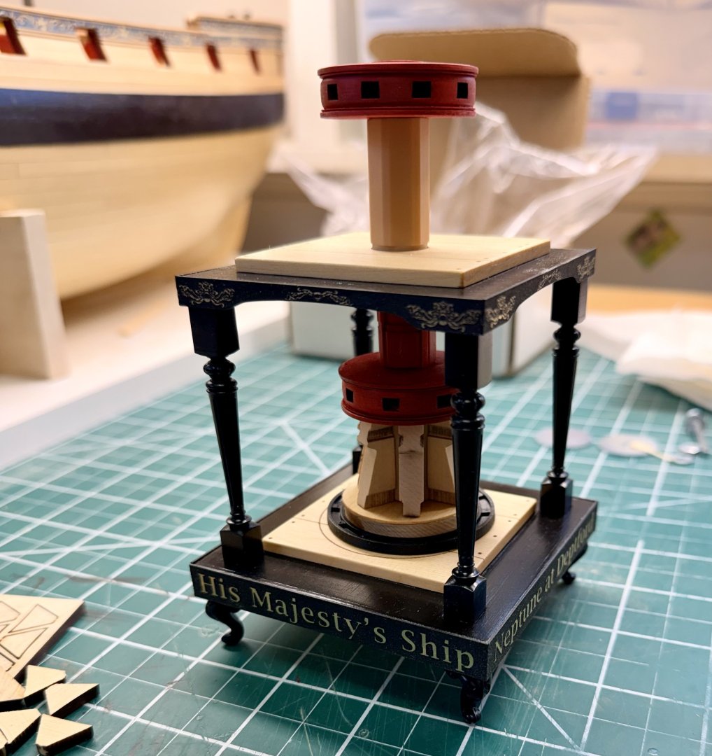
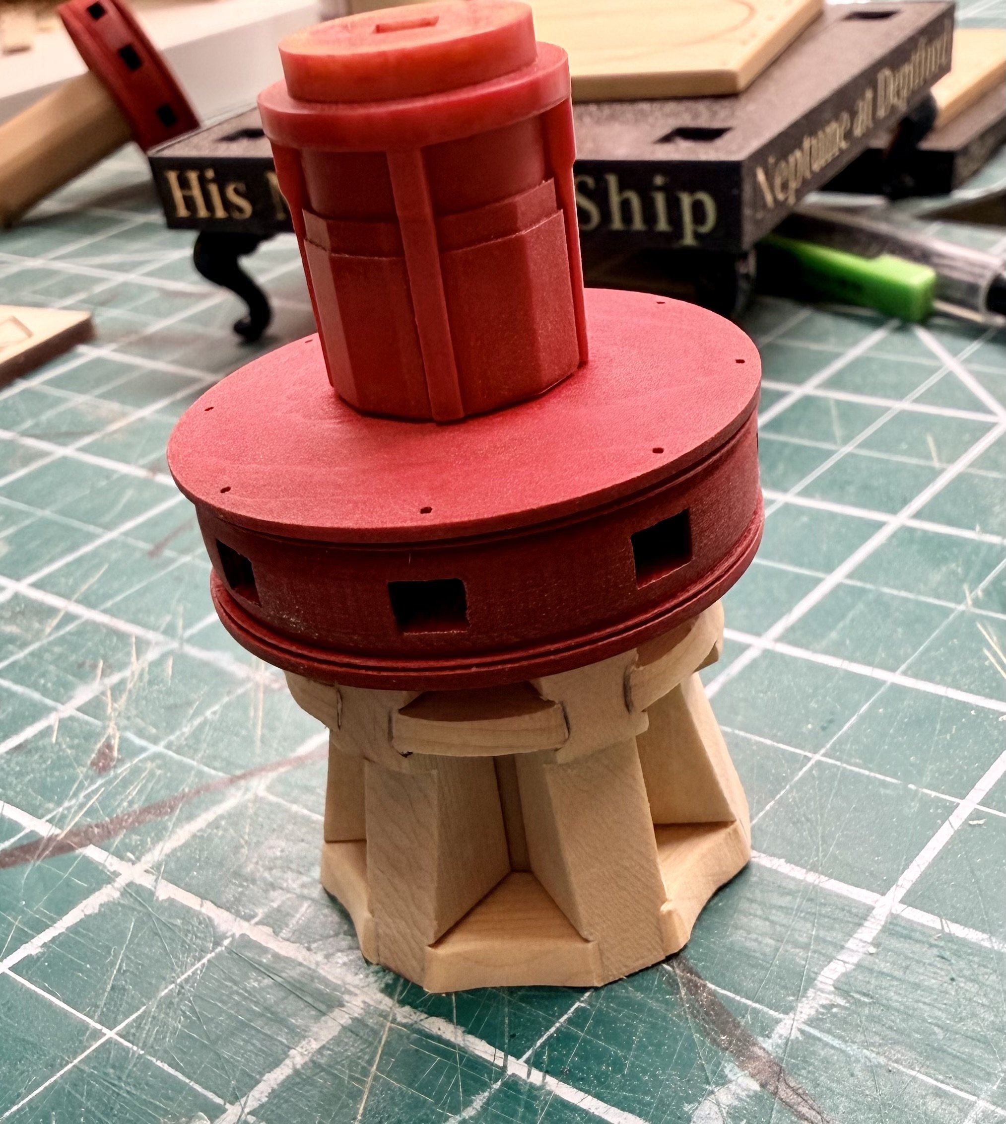
An update with the work completed the past few days. I got the first couple coats of crimson paint on the drums and then added the column pieces. Then I started adding the whelps to the lower capstan. I most likely put more thought into how to glue them on with uniform spacing then was really necessary, but this is how I eventually decided to do it. I glued on one pair of whelps that are opposite each other, being as careful as possible to get them lined up opposite each other and placed evenly along the column. I normally use CA to glue printed parts, but in this case I used regular wood glue to allow me time to reposition the whelps. With these two whelps installed and the glue well set, I then added the whelps in pairs, first one side and then the other. I used the chocks as an aid to getting the spacing uniform. using 3 upper and lower chocks to ensure the position of the whelps was correct. I also held the capstan in my bench vice to provide a stable platform to work on this. A couple pictures showing this, the chocks are only set in place as spacers at this point. they still need to be properly shaped and installed once the glue on the whelps has set. And the lower capstan is one step closer to being completed. Then I went back to the display stand. I sprayed a coat of satin clear on all the parts and then added the self adhesive sheets to the lower and upper platforms. The 3M adhesive on these sheets is not repositionable and I treat it the same as contact cement. So I set up the base with a guide stick to help with positioning since I won't have a second chance. Trimming up the edges of these pieces was really easy with a sharp #11 blade and going slow with multiple passes. I then glued the feet to the bottom platform. Here is a test fit of all the parts so far. Nothing is glued together at this point (and yes the columns are upside down) Steve

-
shauer reacted to a post in a topic:
HMS Portland 1770 by scrubbyj427 - 1:48 - 4th rate 50-gun ship
-
Good to know. I'll add the matte clear before assembly.
-
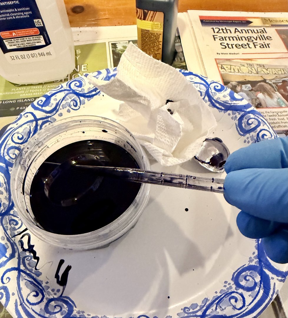
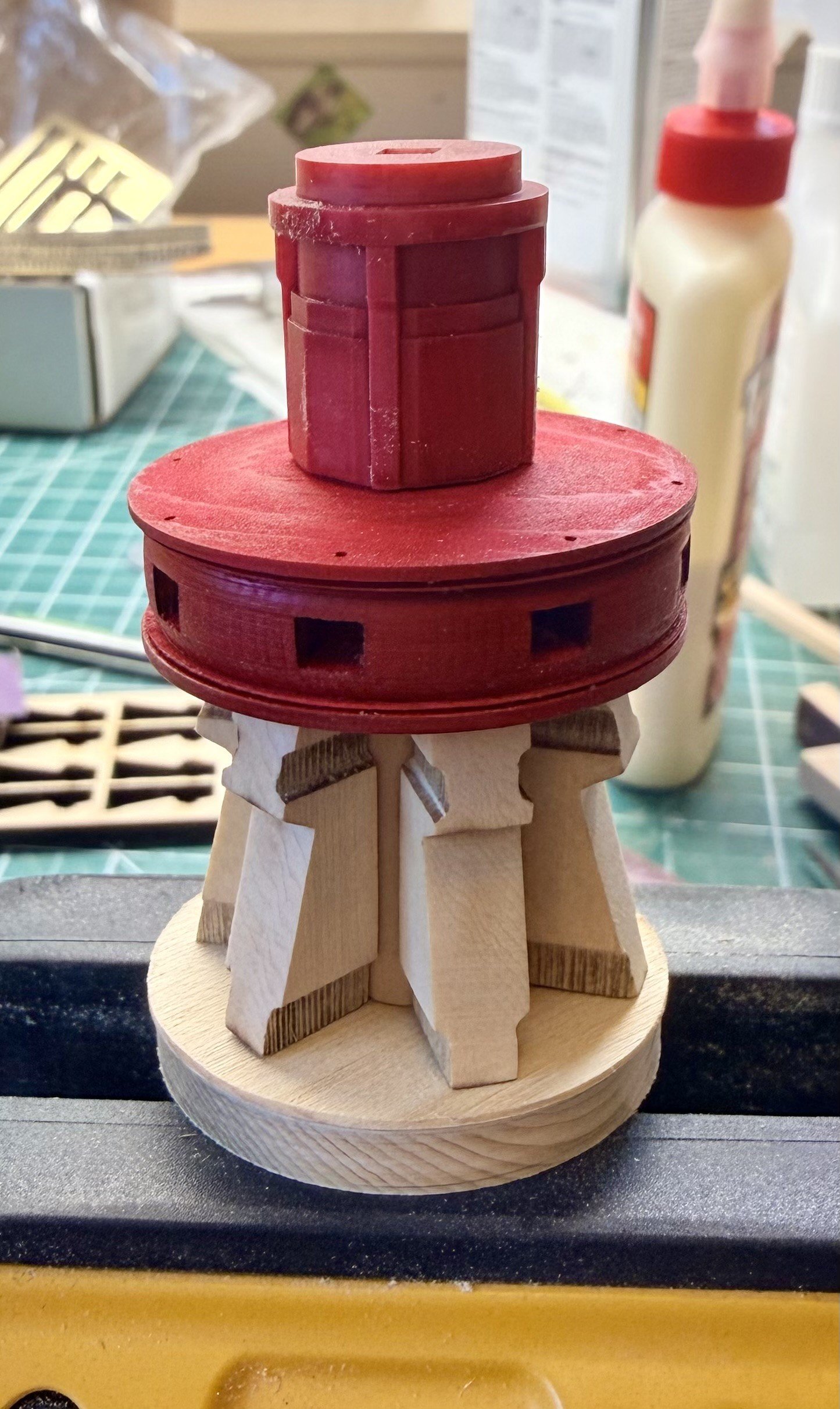
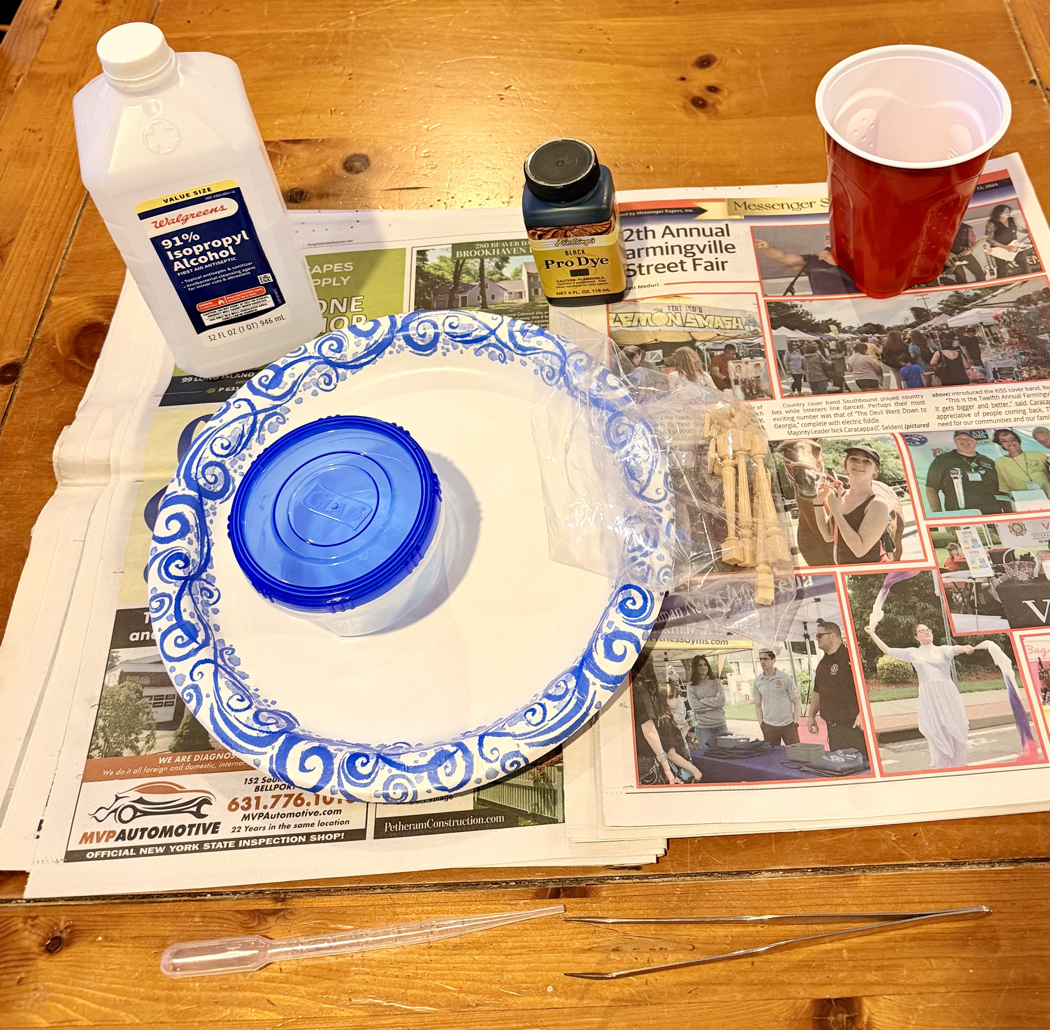
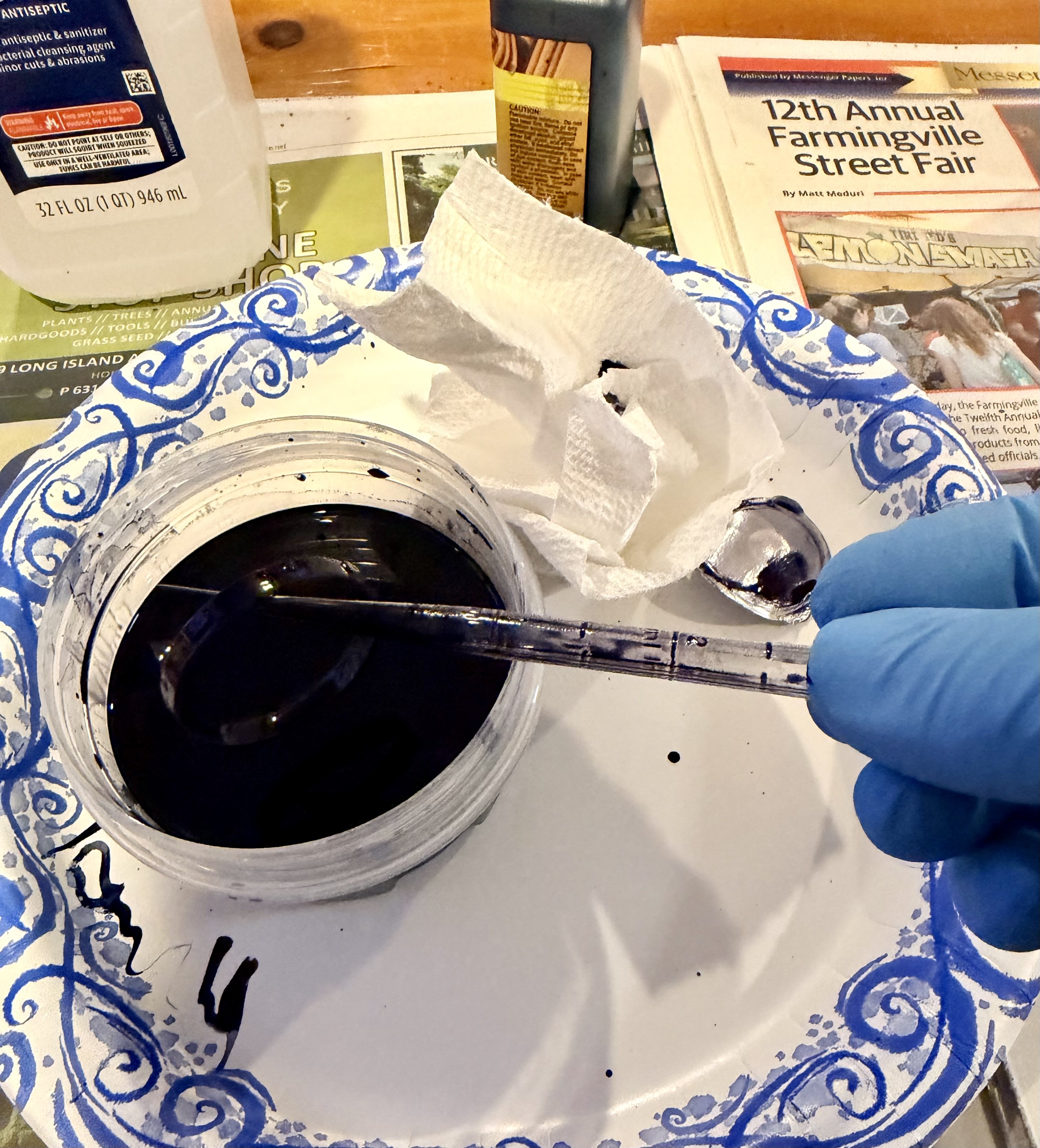
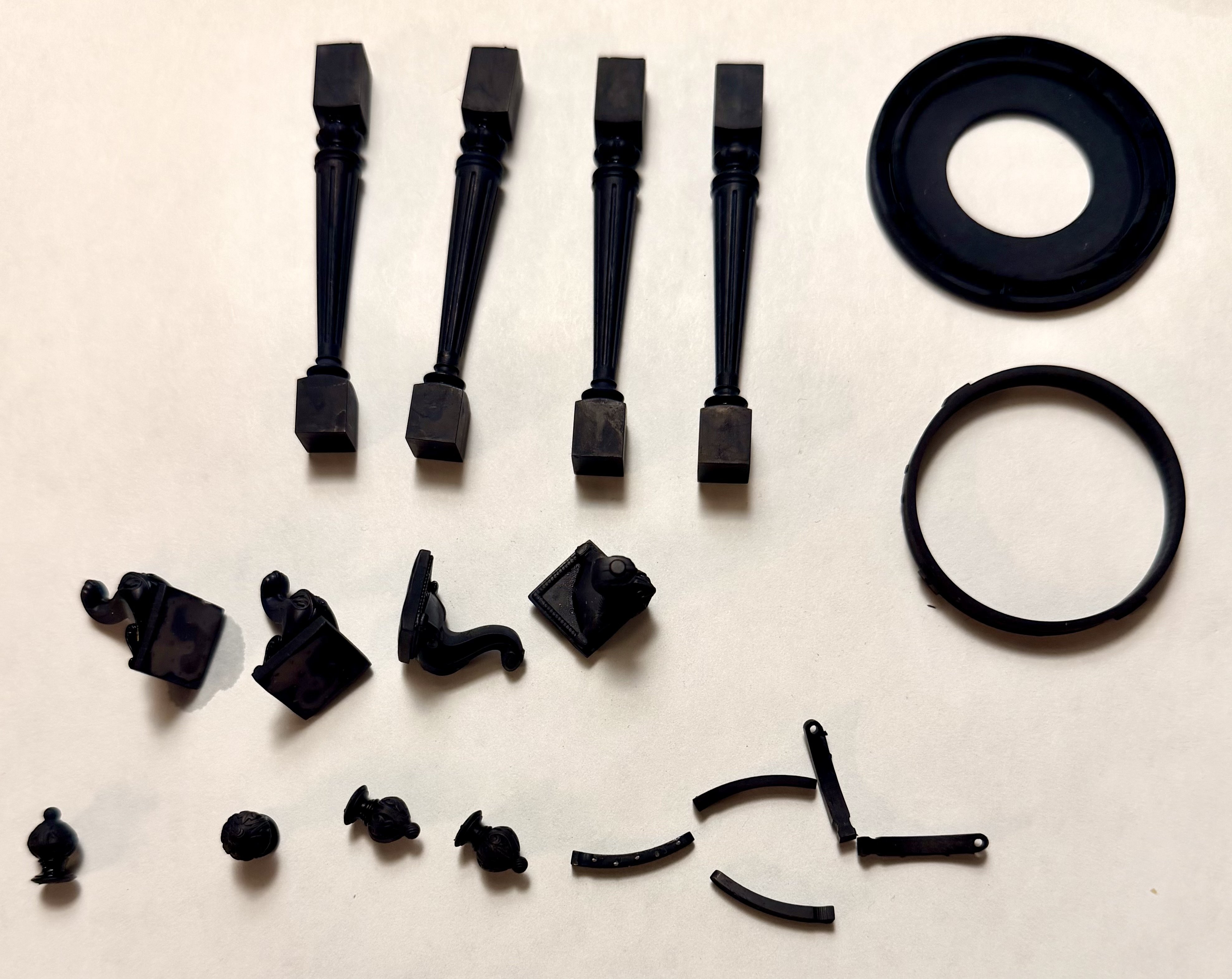
Just a quick update, had time to put another couple coats of black on the display stand, and my black dye arrived so I got that job done. Just followed Chuck's guide on using the dye, made sure to get the alcohol based 'pro' dye since I was diluting it with IPA. (not the beer...) Simple set-up to soak the parts in a small container. Mixed some of the dye with the alcohol until it looked "dark enough" I guess I ended up at about 10:1 but that's a guess. Tried a 25-30 minute soak Fished the parts out of the dye and washed them with water. I noticed there's a difference in the dye absorption. Areas that I had sanded down and smoothed out showed lighter than the "raw" 3d printed surfaces. This did not impact me as these were all mating surfaces that will not be seen. However, the smooth surfaces on the columns also showed slightly lighter than the center portions with a rougher surface finish. You can look at the square portions of the columns in this picture below. Simple solution, I just put these parts back in the dye bath for an hour and that looks like it took care of it. I can see if you were sensitive to the final shade of the parts, then surface finish would need to be taken into account. With something like black, you don't really care so the longer you soak the parts, the better. Never done this with printed parts before, I will definitely be using this technique to color printed parts a solid color where careful control of the shade is not required. The finish is far superior to a painted finish for this application. Steve


-
shauer reacted to a post in a topic:
HMS Portland 1770 by scrubbyj427 - 1:48 - 4th rate 50-gun ship
-
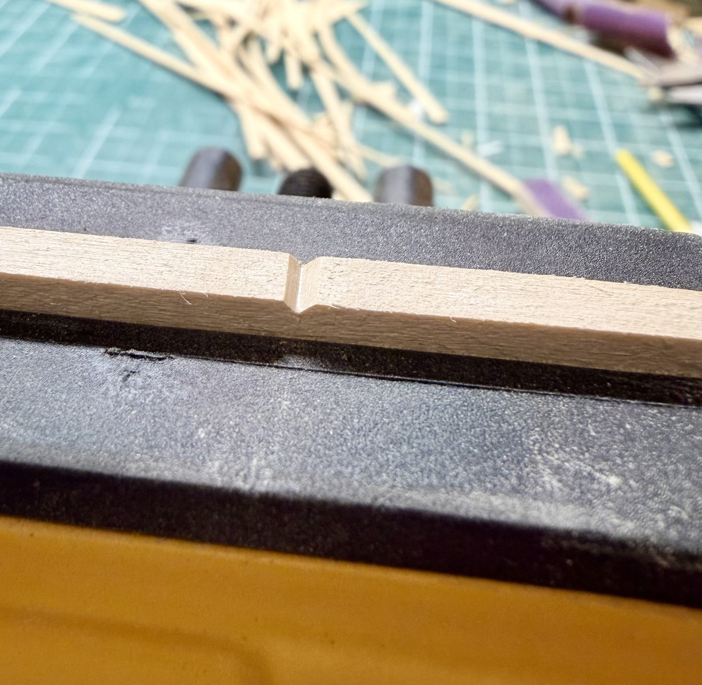
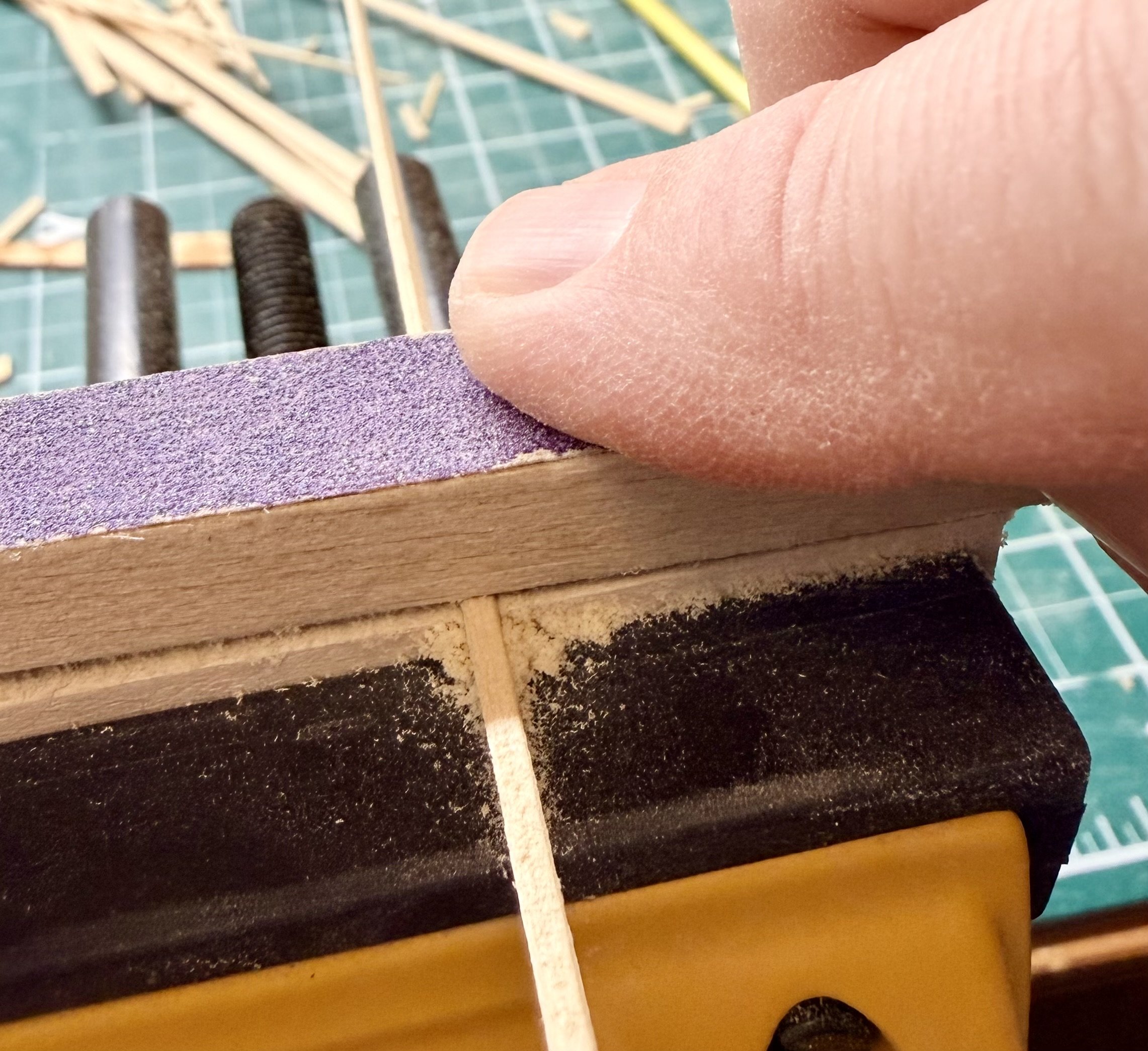
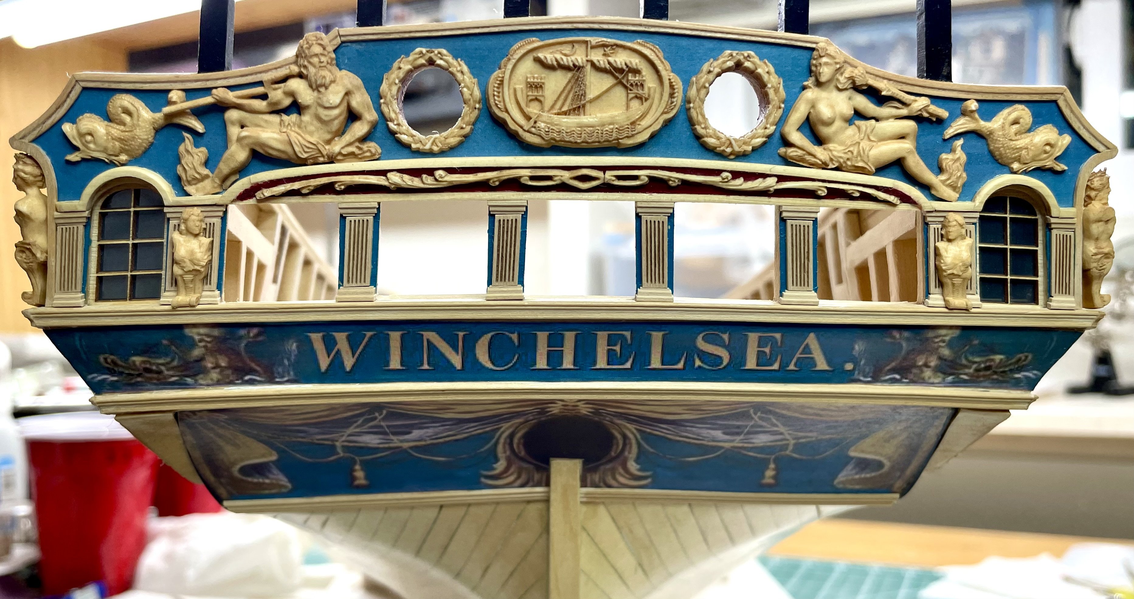
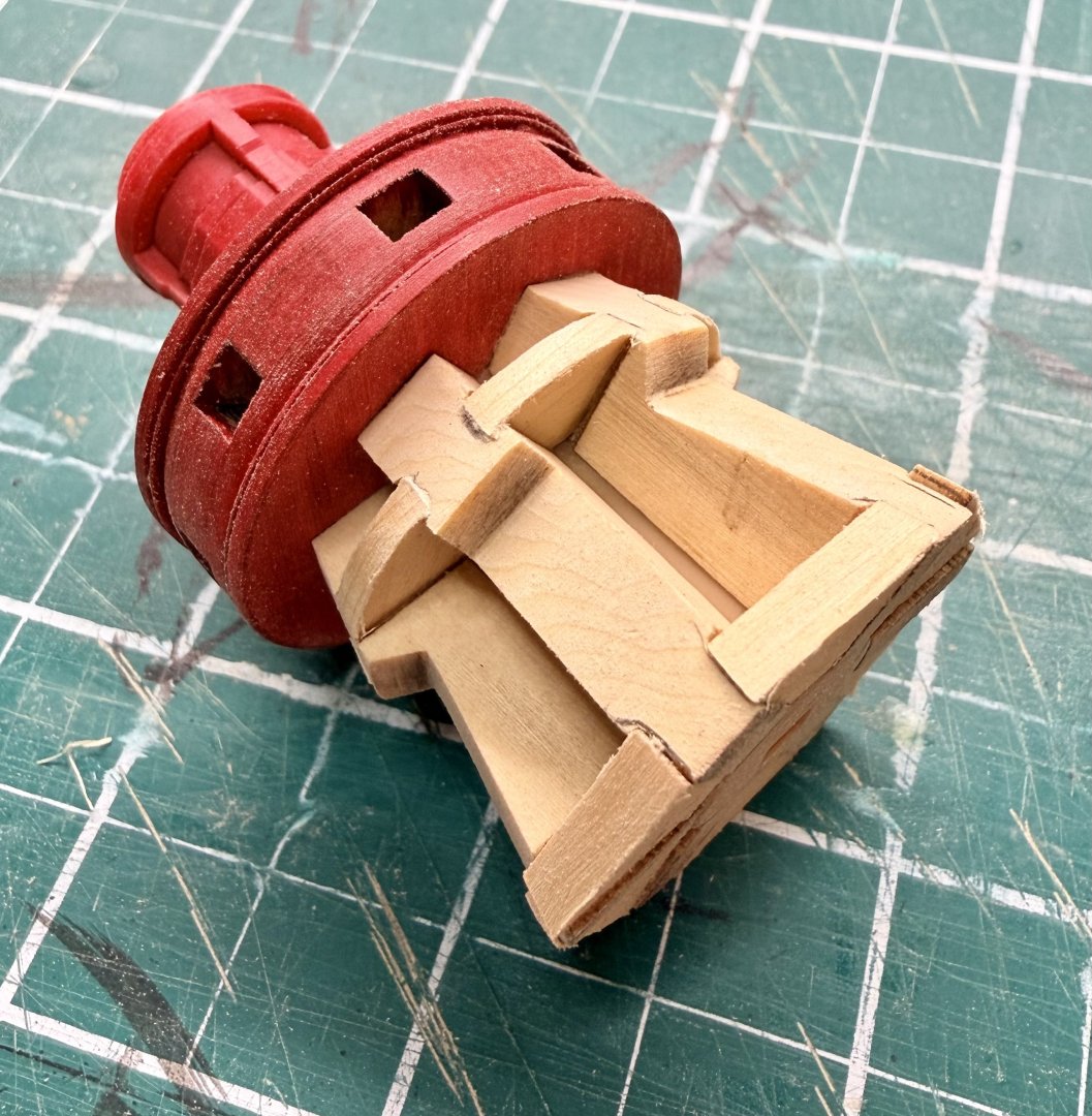
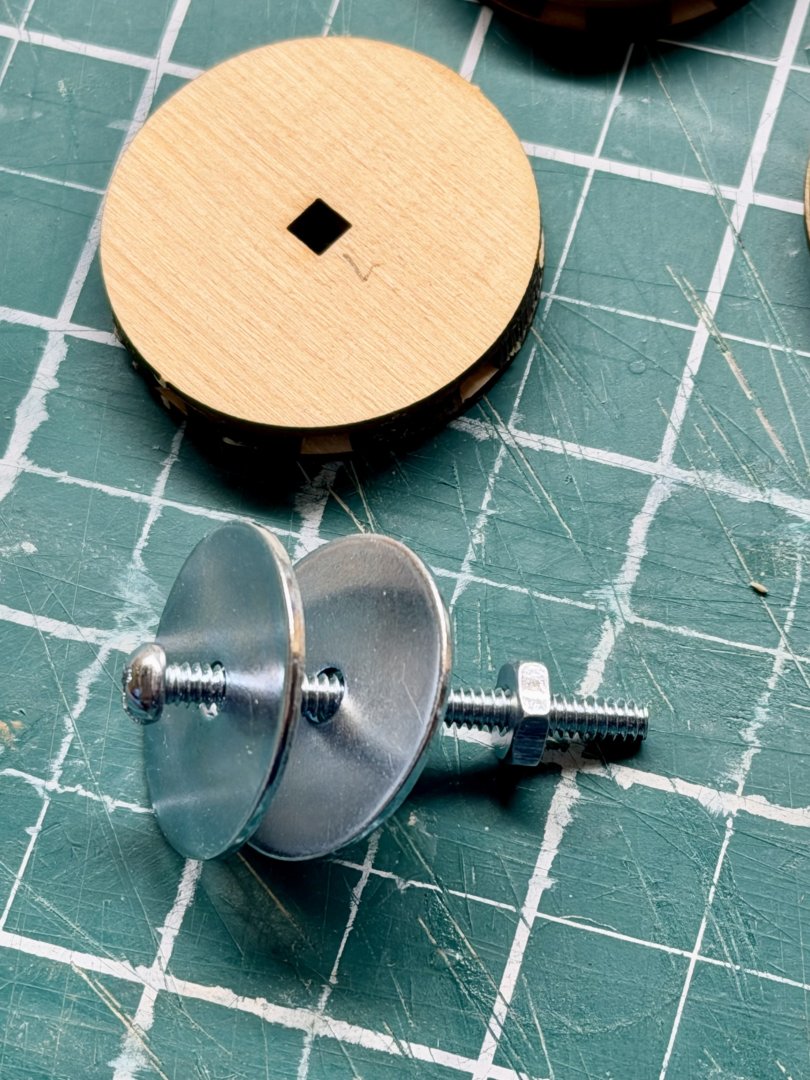
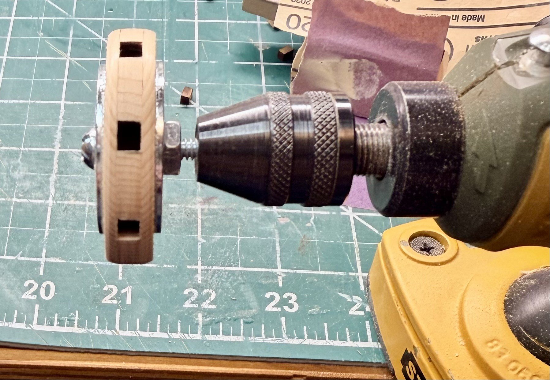
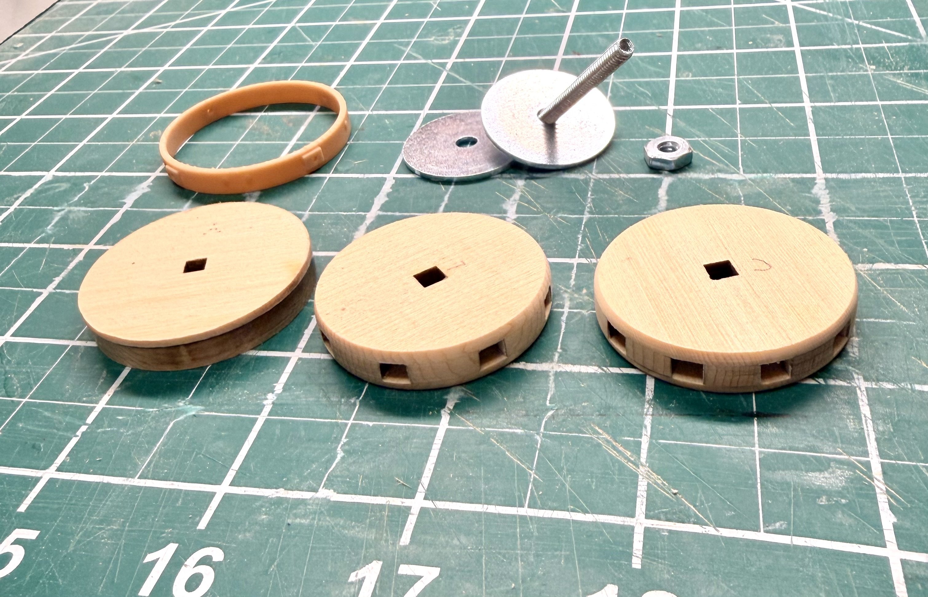
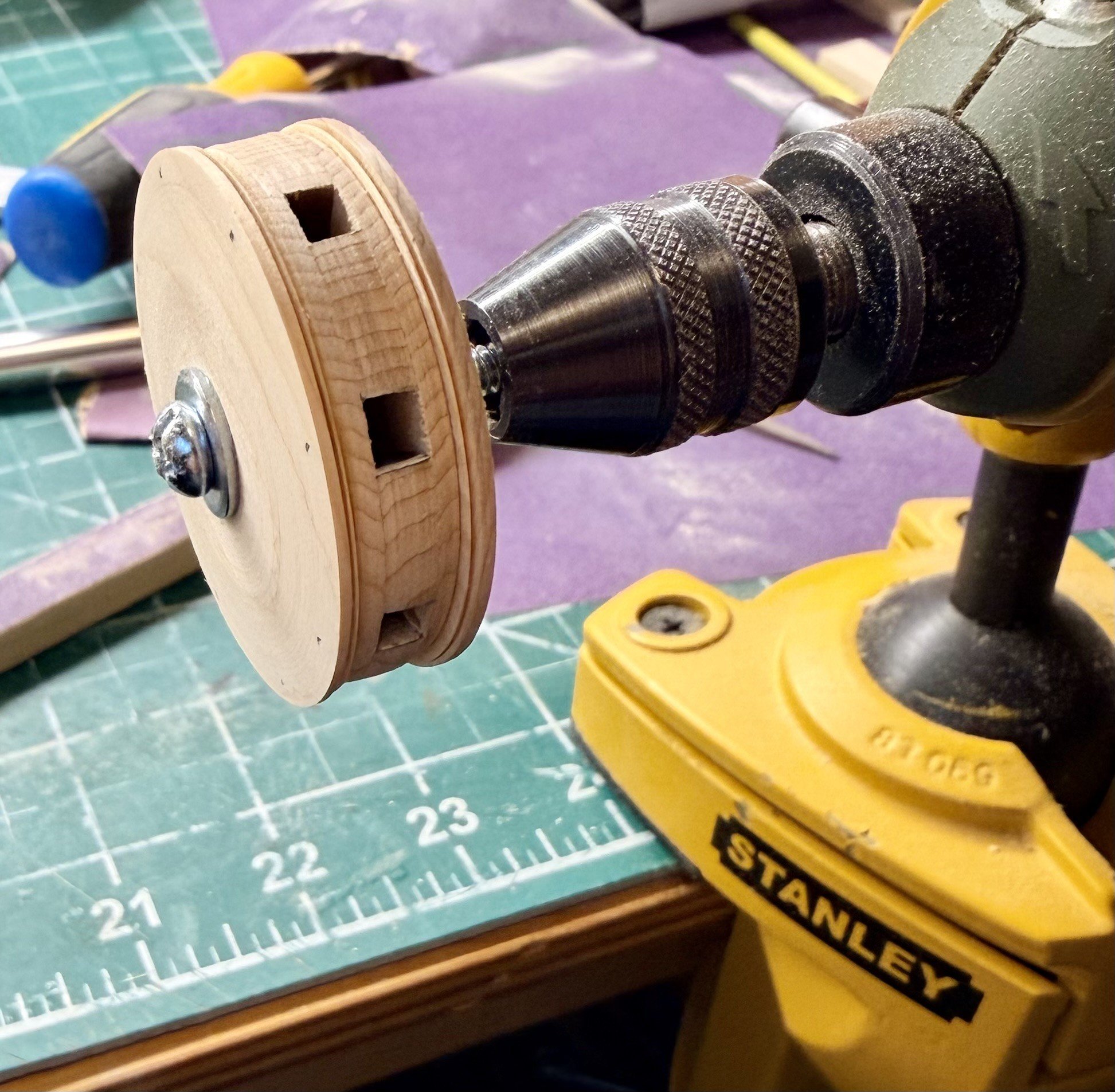
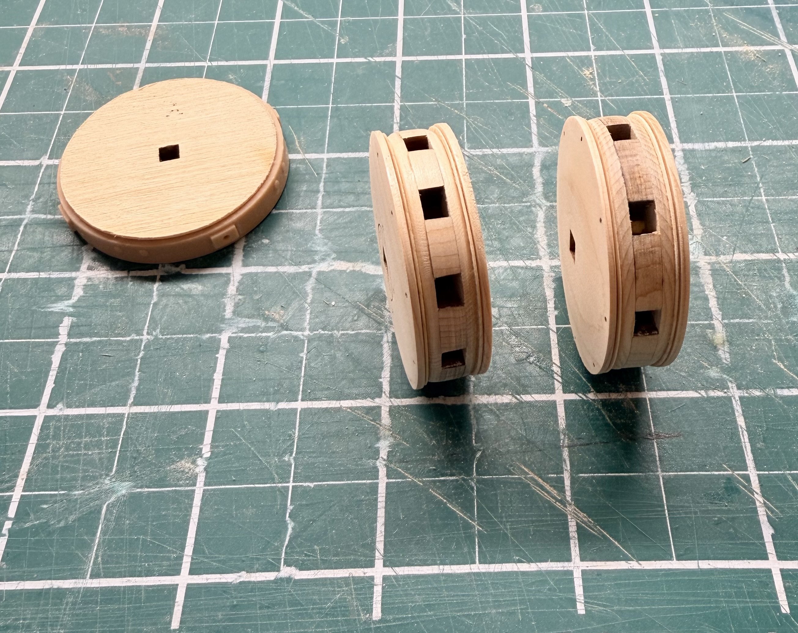
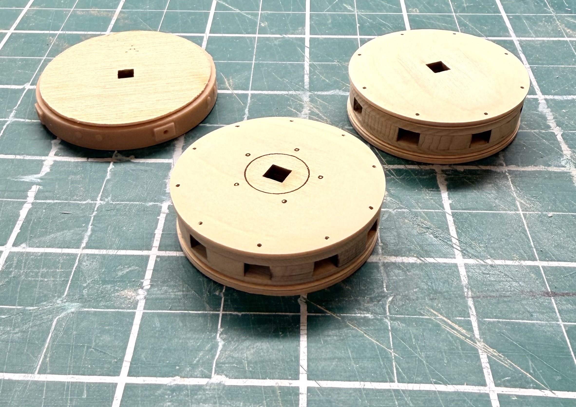
I'm using this as the trial run prior to constructing the capstan for my Winchelsea, which will be half this size. I applied the first coat of wipe on poly to all the base pieces as either the final finish or as a sanding sealer prior to painting. While waiting for that to dry I decided to spend yesterday evening and this morning getting the drums assembled and shaped. I have the black dye arriving tomorrow so I can dye the printed parts black. I like working through similar operations at the same time, so I did the upper and lower drums at the same time. Be sure to label them as they are different. I refined the technique that Chuck showed of using the 1/8 inch square stock as an axle to turn the drums from a cordless drill. I created a mandrel from a #6 machine screw that's 1.5 inches long and some flat washers. This is then chucked into my rotary tool which I have held in my bench vice. The #6 machine screw is an almost perfect fit for the hole in the drum, an M3.5 would be the closest metric size I think. I used 1/8 inch by 1 inch fender washers for all this work except for the final shaping of the tops of the drums. The larger the surface area the better. Drum installed in my rotary tool and part way through shaping with files and sanding sticks. Shaping of the inner layers of the drums completed. For shaping the tops of the drums, I used a smaller, regular sized #6 flat washer to allow access for shaping the taper on the top. The LD-3 and UD-3 pieces are only 1/64 of an inch thick. These were a challenge to shape the required rounded edges on. I did the best I could during assembly but found that running a piece of sandpaper edge-wise along the groove while turning the piece cleaned up the transition pretty well. A couple pictures of the completed drums, except for the center cap on the upper drum. Steve


-
shauer reacted to a post in a topic:
Le Rochefort by Some Idea - 1/24th Scale - First POF Build
-
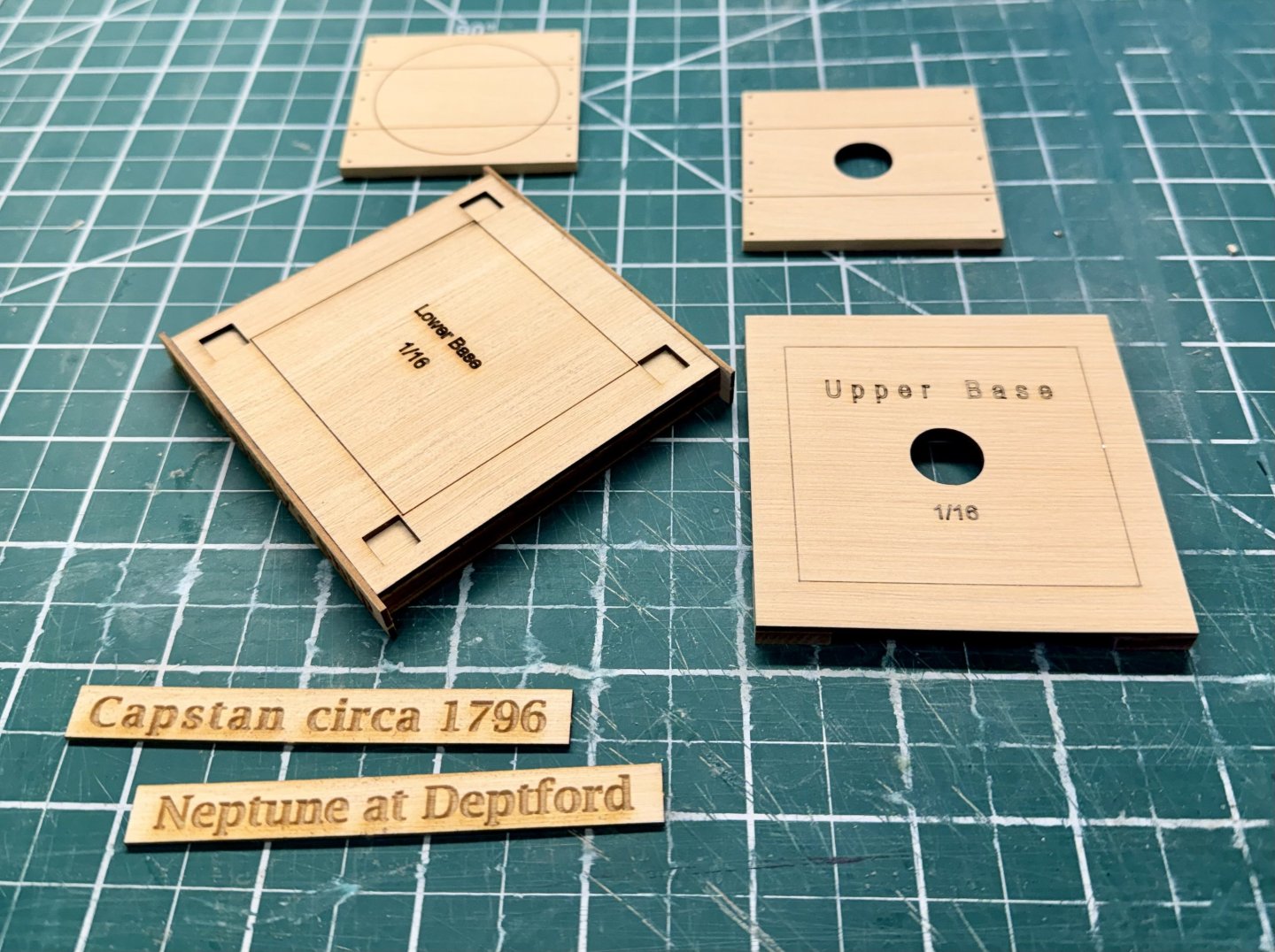
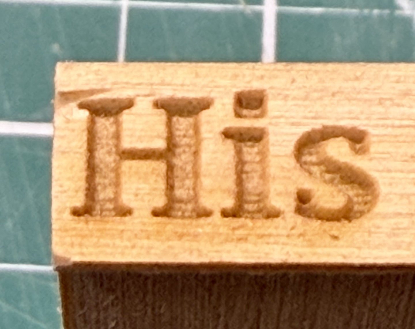
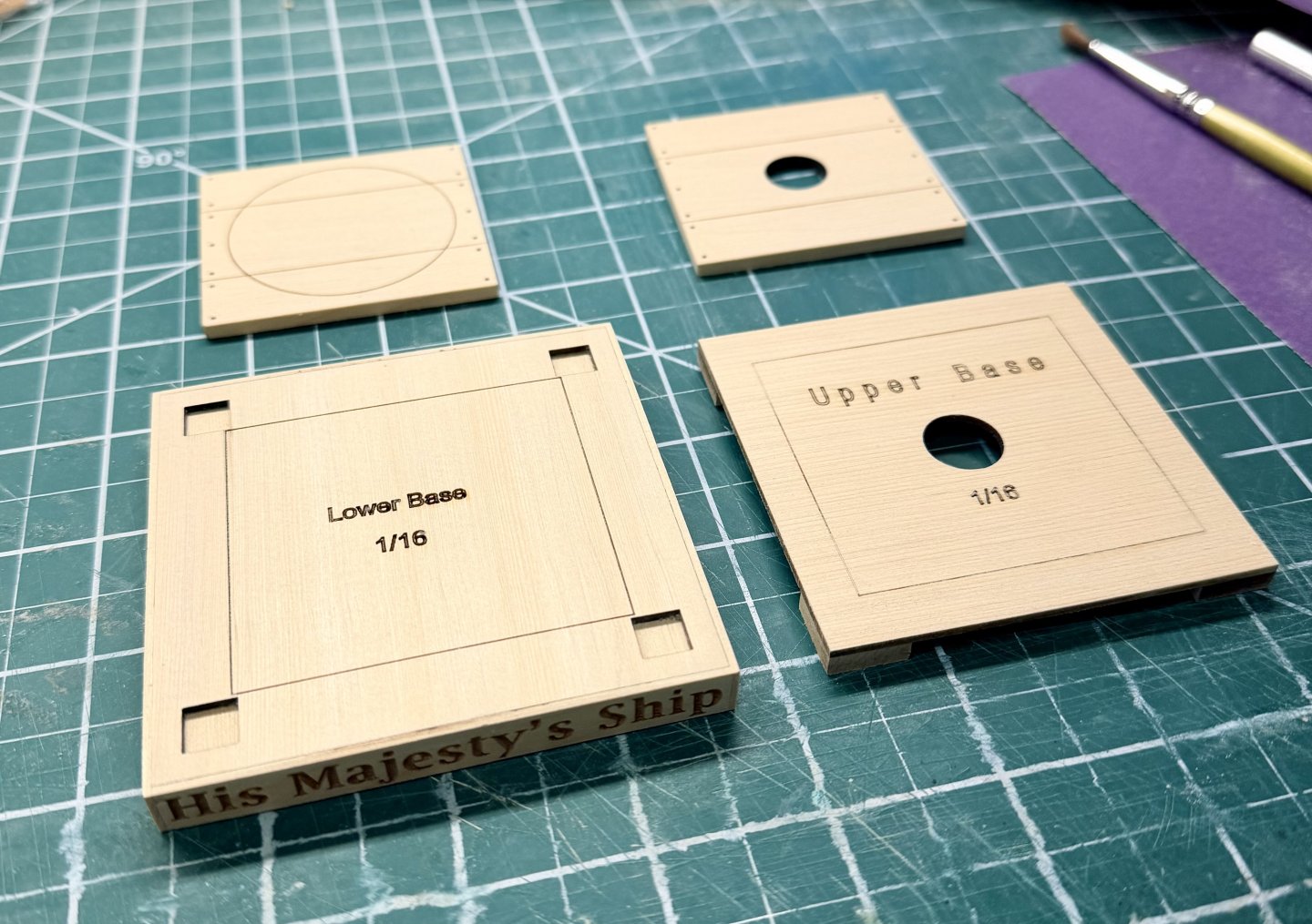
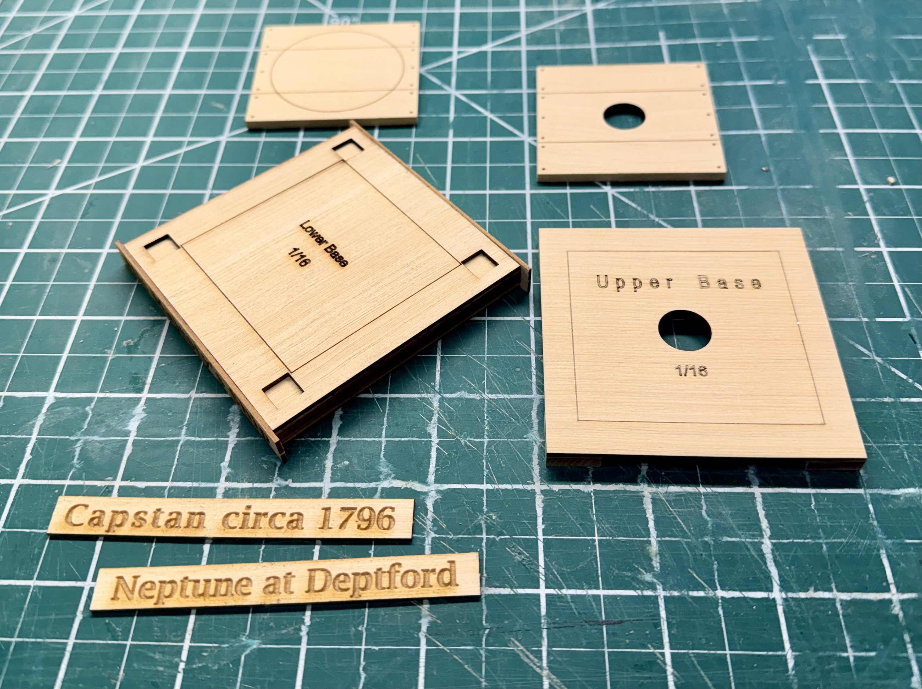
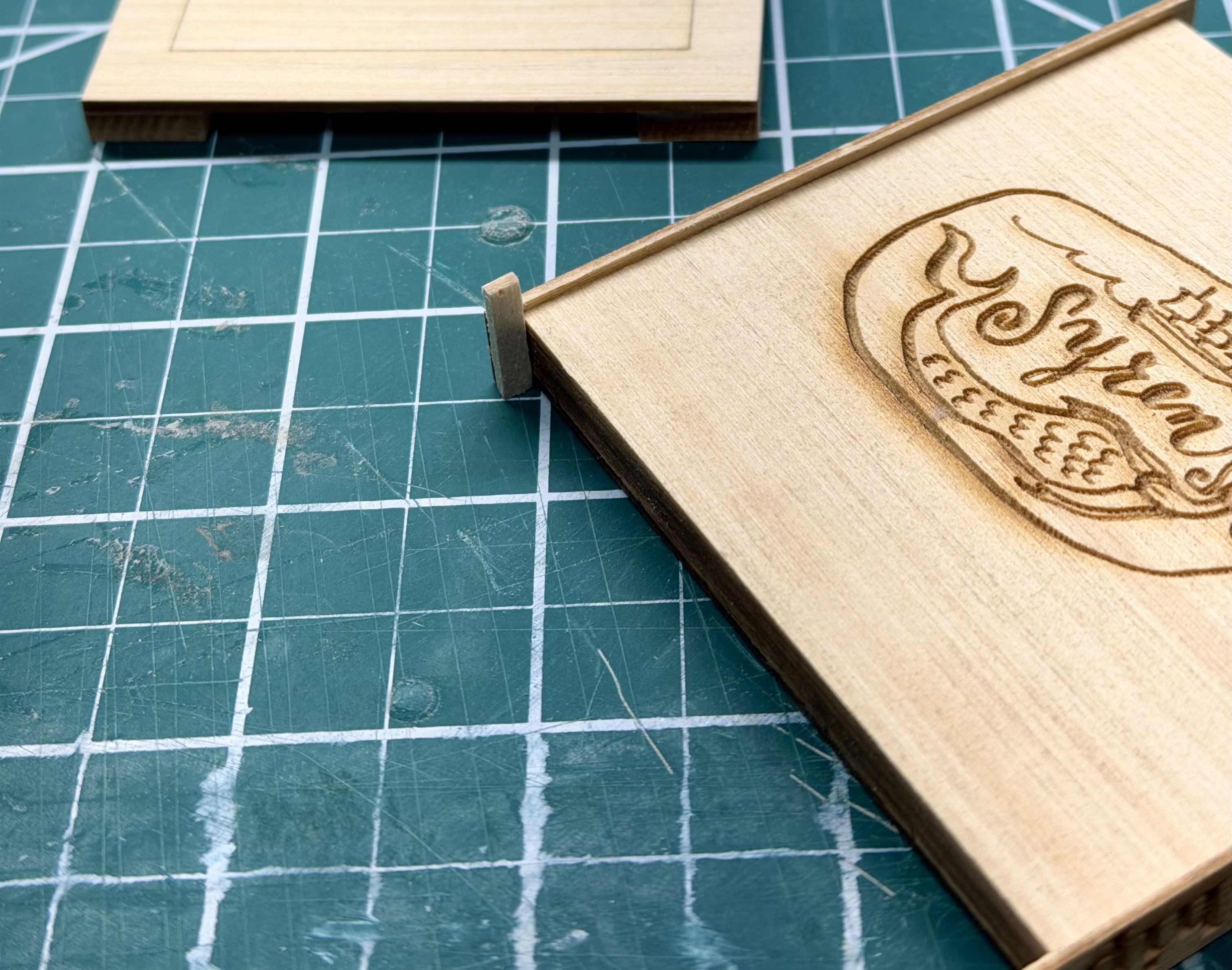
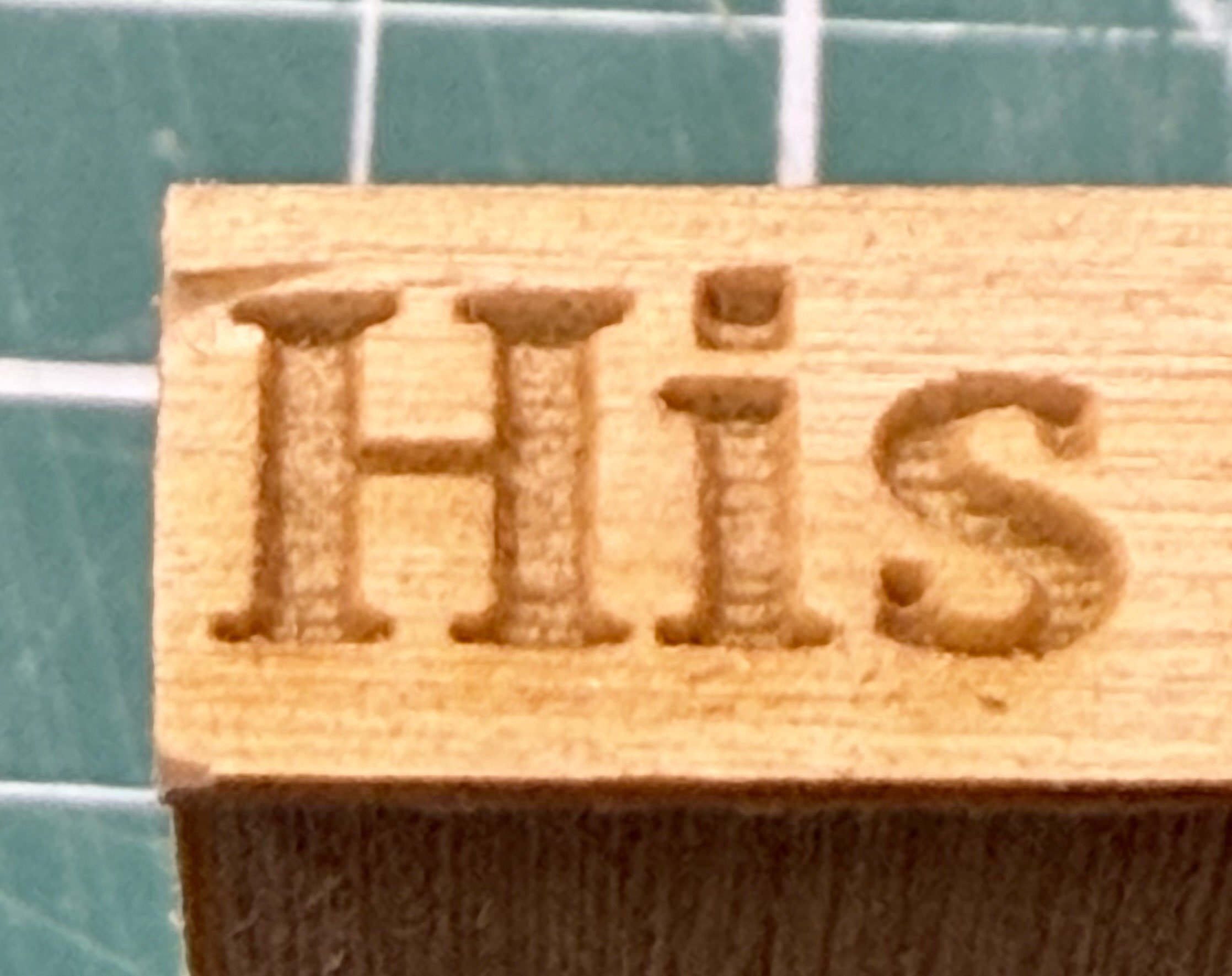
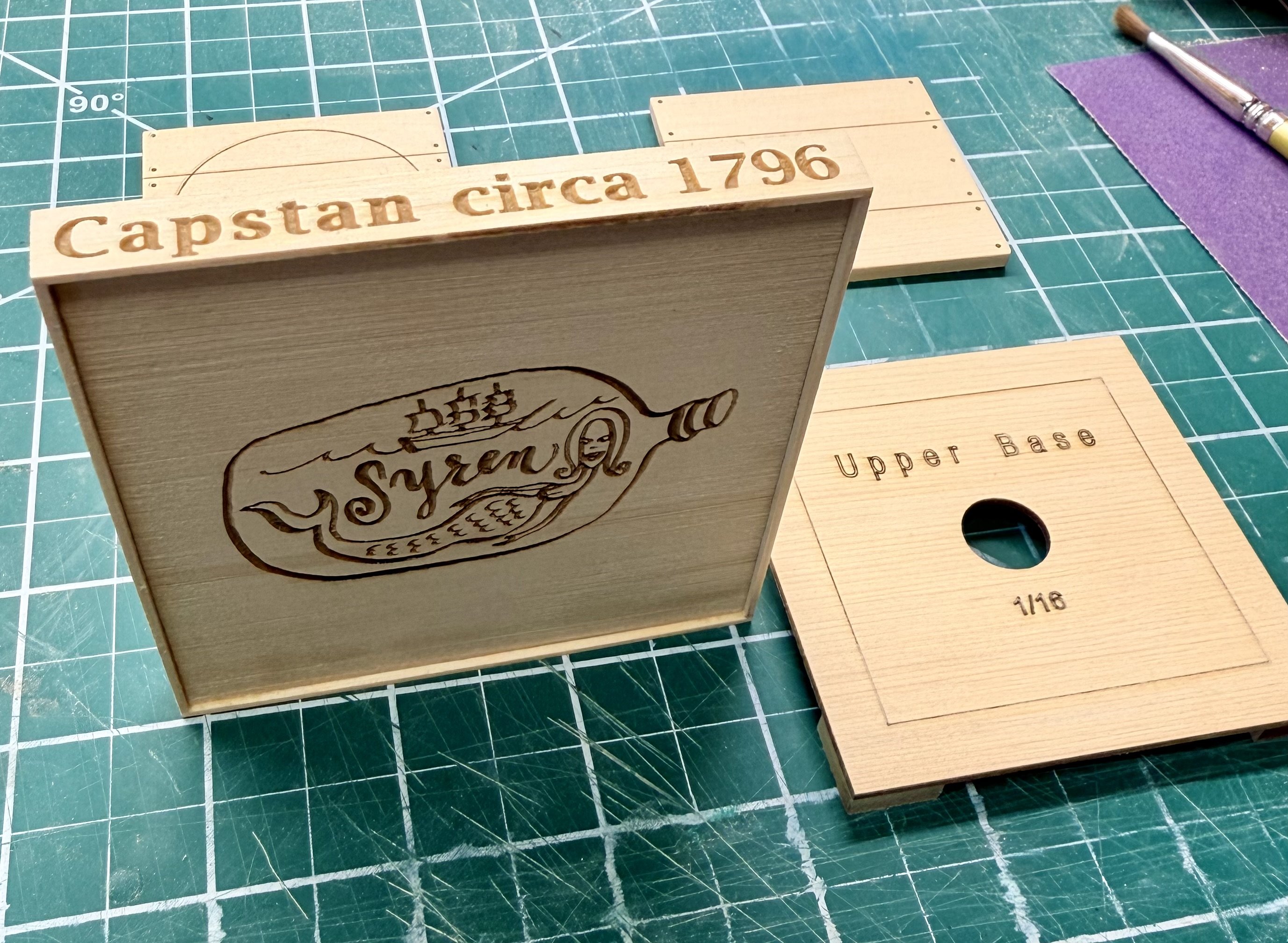
Thanks! First impressions are that this is a really nice small project that balances a high level of detail, but it is easy enough to build that it would make a nice novice project, especially in kit form. Spent the evening putting the wood parts of the base together. Keeping the partners separate from the lower and upper base until I have the bases painted black and a first coat of wipe on poly on the partners. Part way through assembly of the bases with the 4 squares mounted on the underside of the upper base and two of the 4 side pieces on the lower base. Following the build guide, installed two opposite sides on the lower base. The overhang ended up being 1/8 inch so just used a piece of scrap as a gauge. You could have also used the included 1/8 square stock that makes the axel as a gauge. One recommendation, do not install the "His Majesty's Ship" side as one of the two first sides. I discovered that the material along the laser engraved 'H' is prone to tear-out when sanding the edges down flush with the lower base. Saving this side for the second group installed will allow more material on the outside of the 'H' and be less prone to tear-out. Close-up of the tear-out on the edge. I'm going to be using the adhesive boards so this will be covered. And the base assemblies ready for paint and poly. This will happen today. Cleaned up Chuck's logo on the bottom with a light sanding. Steve


-
shauer reacted to a post in a topic:
HMS Portland 1770 by scrubbyj427 - 1:48 - 4th rate 50-gun ship
-
 shauer reacted to a post in a topic:
HMS Portland 1770 by scrubbyj427 - 1:48 - 4th rate 50-gun ship
shauer reacted to a post in a topic:
HMS Portland 1770 by scrubbyj427 - 1:48 - 4th rate 50-gun ship
-
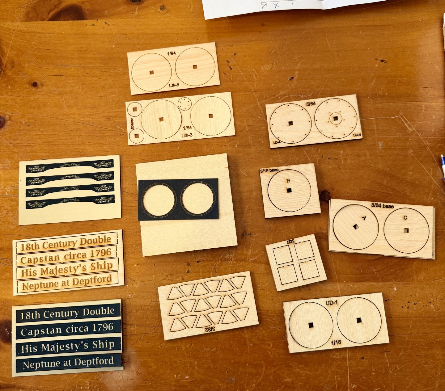
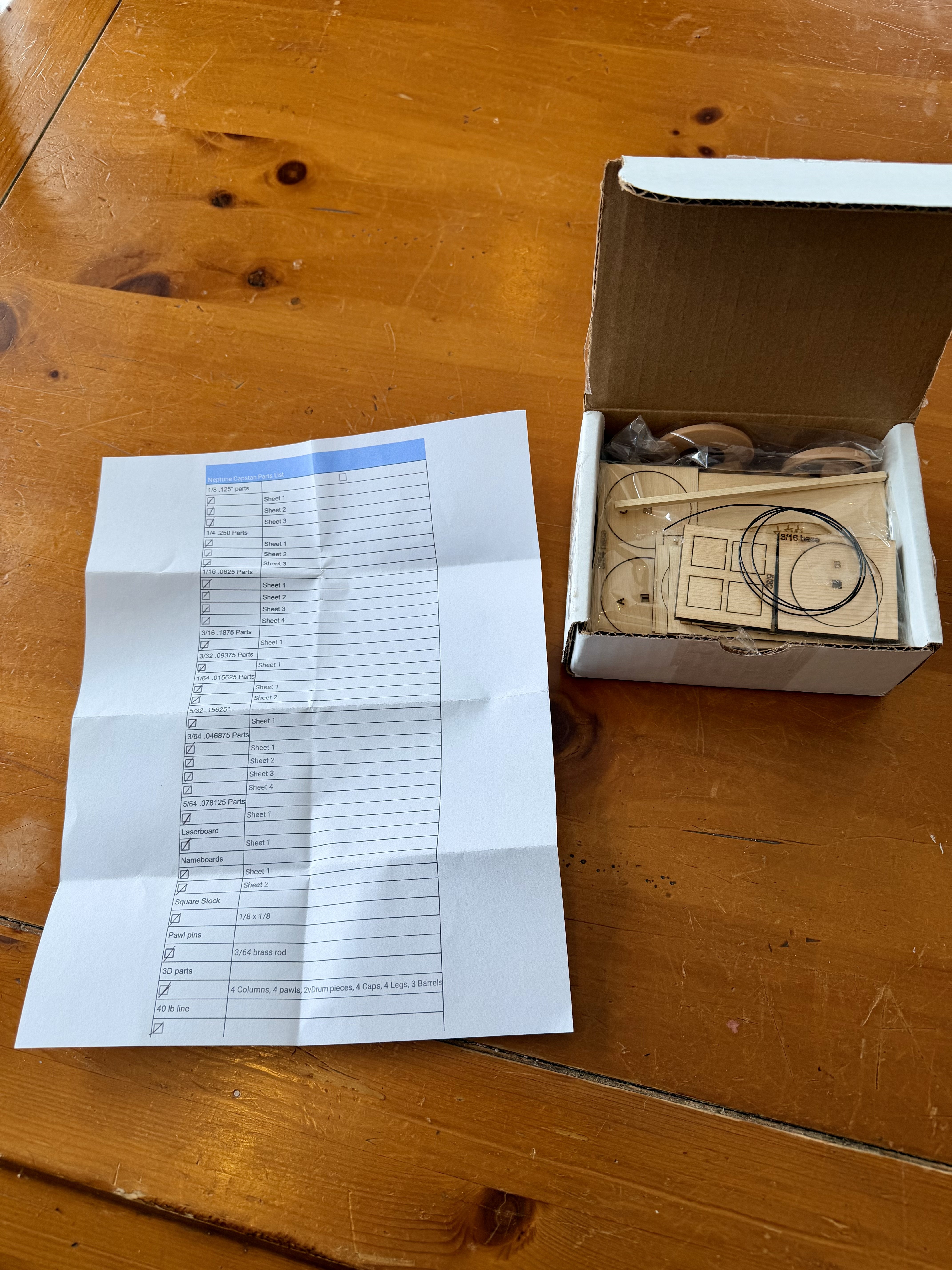
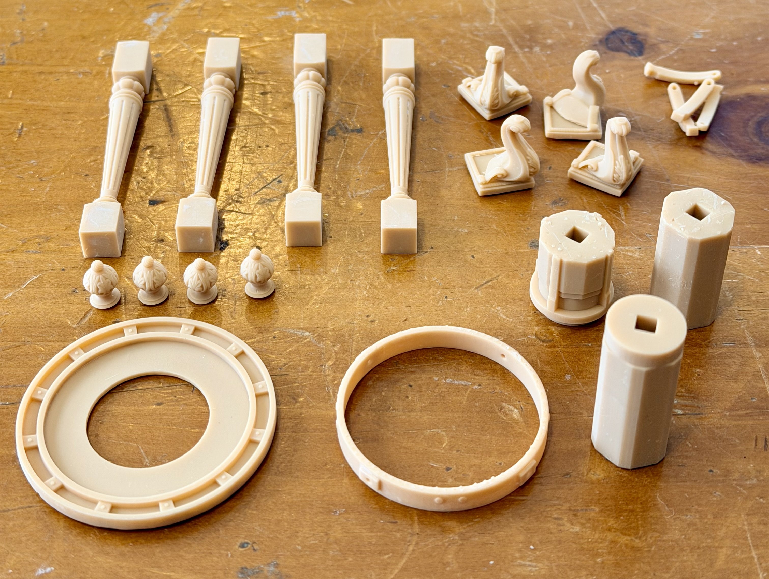
Looks like I'm the first build log here, mods please let me know if anything is incorrect. I don't have access to a resin 3d printer or a laser cutter at the moment, so the kit option that Portland Scale Ship is offering was the way to go for me. I'll be working on this small kit as a needed distraction from my Winchelsea project. Just needed something small to give me a change of pace for a bit and will be working on both these at the same time. Small box arrived and I was pleased to see an included packing sheet provided for this small kit. The box is just about the perfect size for the kit components so no additional packaging was needed beyond the plastic bags used to hold the parts. Three bags of parts plus a length of 40lb monofilament line, the 1/8th inch square stock, and a short length of brass wire. Printed parts are all very clean and will require minimal cleanup Laser cut parts from one of the bags, not going to show the other as all the parts are already shown on the Portland website. Laser cutting is all very clean. Overall the part quality looks to be the same as the parts I've been receiving from Syren for my Winchelsea chapters. Looking forward to putting this together. Thinking I will display it in my office once completed. Steve


-
My capstan kit was waiting in my mailbox today. Had not expected 2nd day delivery from across the country when I ordered. Arrived without issue and in good condition thanks! Steve
-
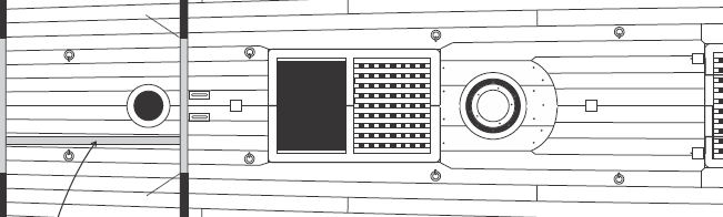
I need some clarification on a discrepancy between the chapter 4 instructions and the details on the plans. Getting ready to spend my 3 day weekend working on the deck planking. The instructions show that there is a single center plank that spans the centerline of the deck and that there are 7 strakes that make up the planking between the coamings and partners. Plan sheet 3 shows the deck detail and a pair of center planks, 1 on each side of the centerline and 8 strakes in between the coamings and partners. 7 planks from the instructions: 8 planks on the plans I spot checked a few build logs and did not see this discussed, however I could have easily missed it in the volume of info in the logs. Is there a reason for this difference? Which way is more "correct" I'm thinking the the 7 plank arrangement shown in the instructions will work better with the 1/4 inch planking. Steve
-
I figured out what my temporary distraction from my Winchelsea build will be. Wonder how this capstan will look on my deck? 🤔 Order place and on it's way. Steve
-
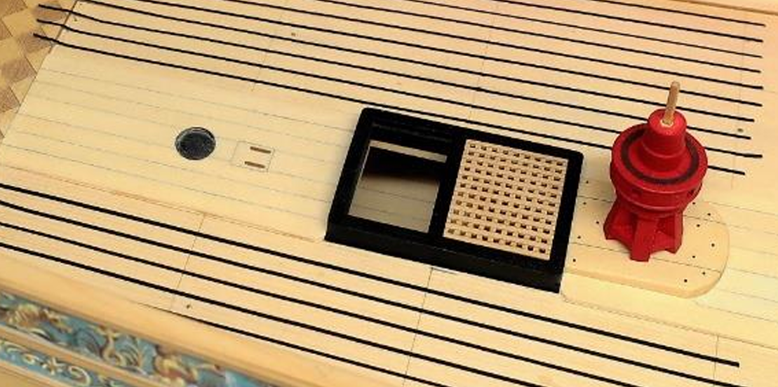
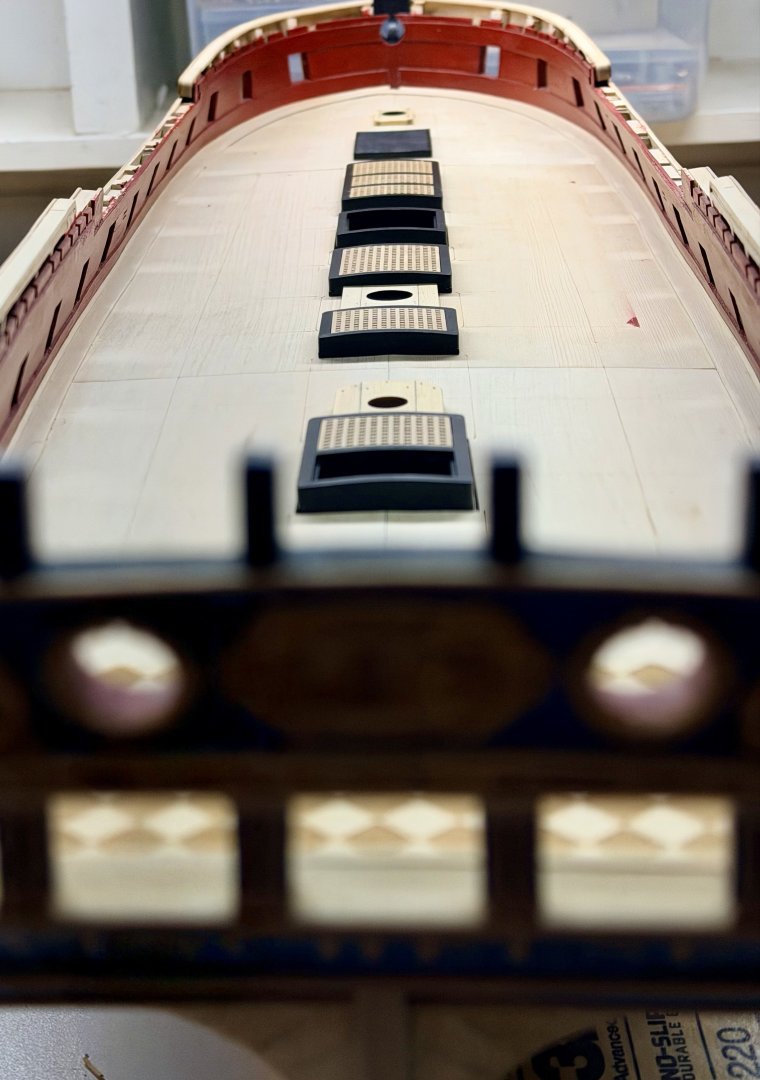
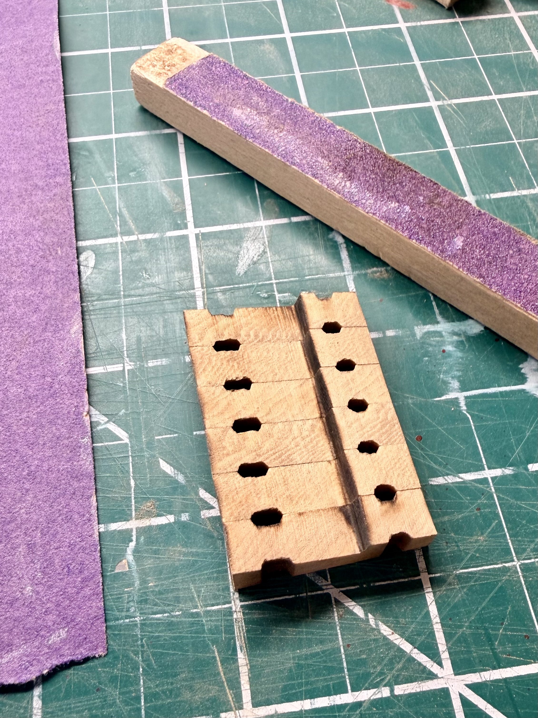
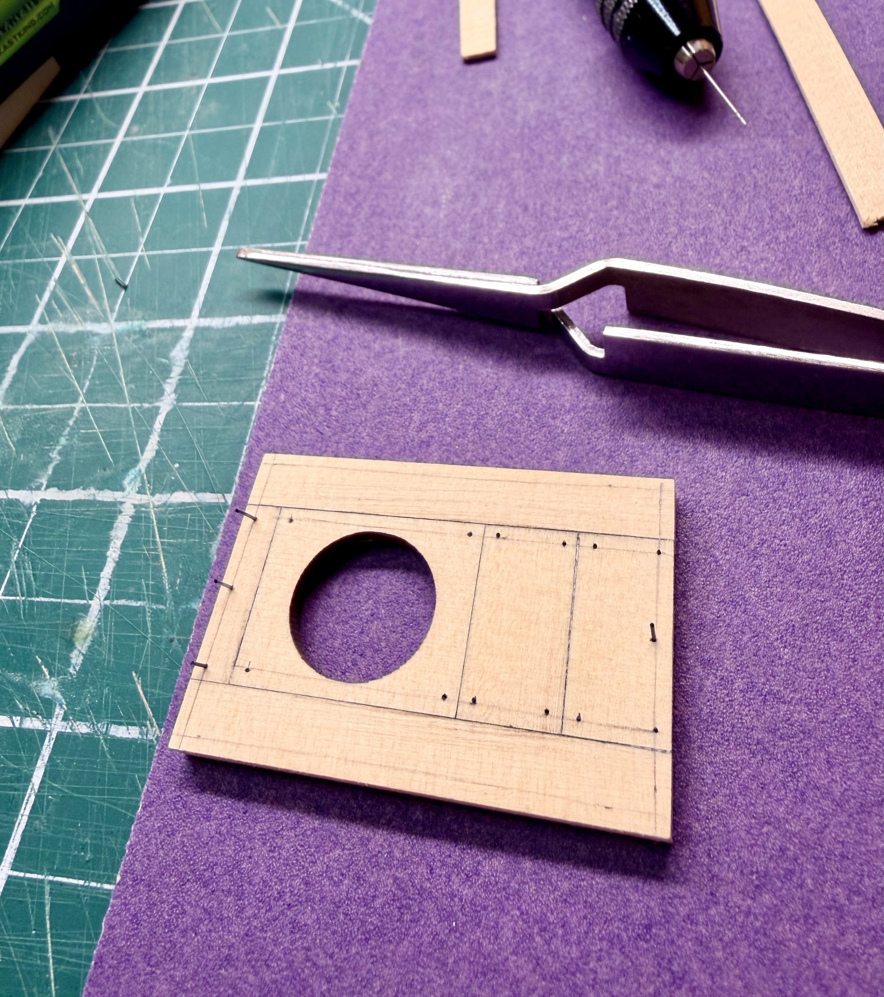
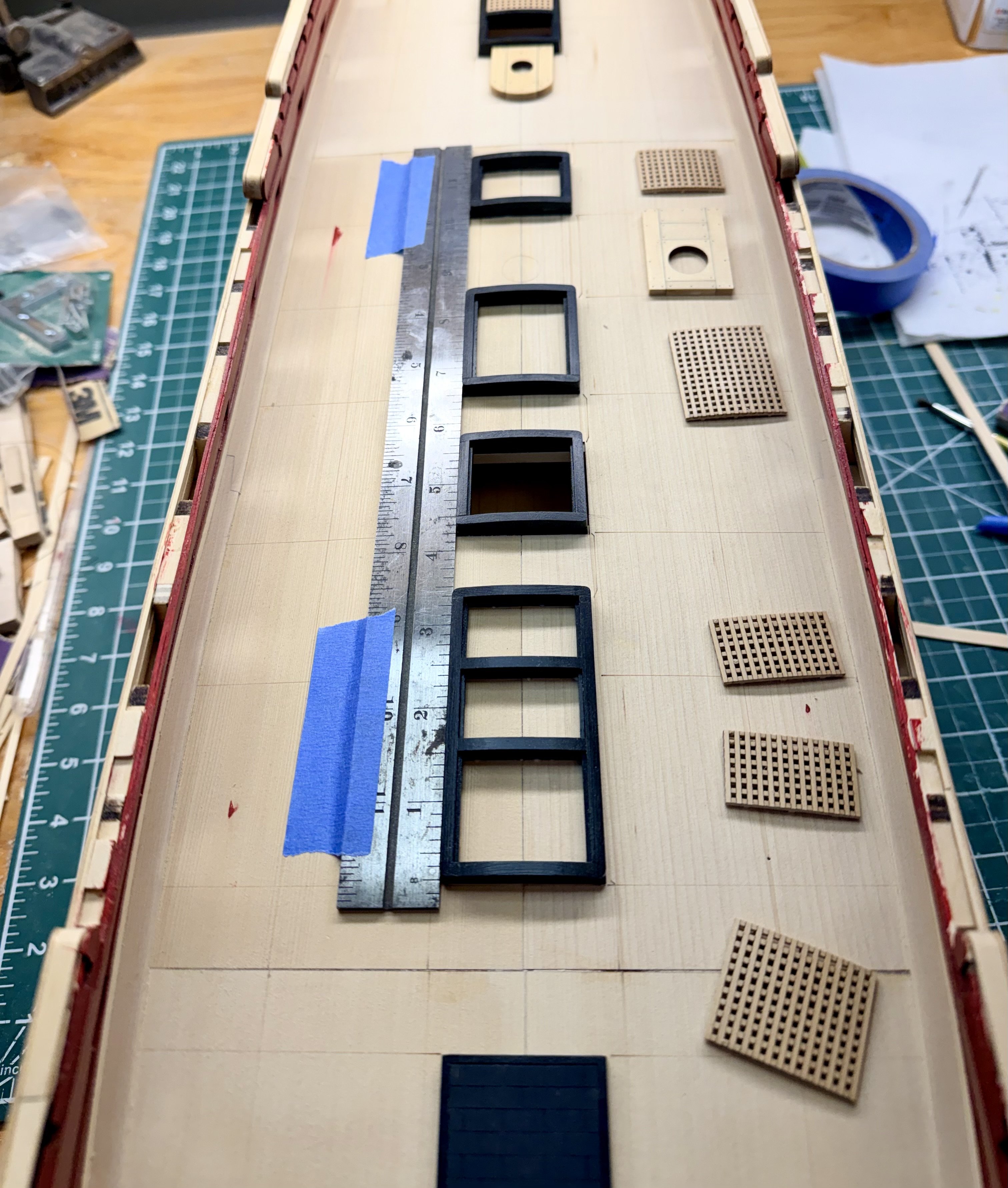
Back to work and real life this week, so progress is back down to my pre-holiday levels. Completed the partners, painted the base color on the stove baseplate, and permanently installed all these onto the deck. One example of using the monofilament line for the bolts on the partners. I don't have a drill press (yet), so all is done with a pin vice and being as careful as I can be to lay out the bolt patterns to get them all looking straight and symmetrical. You can see my layout lines on the work in progress below. A sheet of 120 grit makes a nice surface to hold the workpiece still while drilling the holes by hand. Then started gluing the coamings onto the deck. All the midship coamings are the same width, so I was able to position the forward and rear coamings in this group down the centerline and use a steel rule to ensure the entire group was centered, in line with each other, and straight down the centerline of the deck. Centering the main mast partners between two steel rules running down each side of the coamings. I used a piece of scrap that I sanded until it just fit in the gap on each side of the partners. I checked the forward and rear corners of the partners to ensure they were square before gluing them down. One more example on the stove baseplate. Using scrap shims of equal width on each side to ensure baseplate is centered. Using the sides of the midship coamings as the reference lines. Same technique was used for the rear coaming, foremast partners, and capstan partners. And the pictures of this portion of the work completed. Everything is nice and straight and centered. The forward edge of the capstan partners is shimmed per the instructions so the partners are level. Now onto planking the deck. I may also allow myself some diversions with the stove, capstan, or a few cannon. Not sure yet. Steve


-
Very inspiring work. I'm really enjoying following your journey on this project. This is a level of craftsmanship that I'm aiming to achieve in the future. I can finally appreciate the comment about cutting into your model to install the catheads. I need to emotionally prepare myself every time I cut into finished work. Steve
-
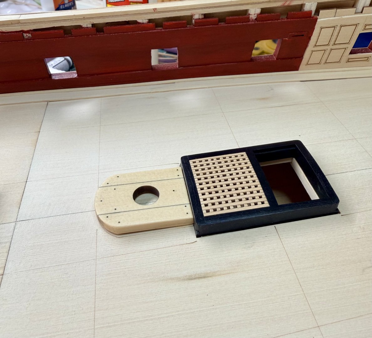
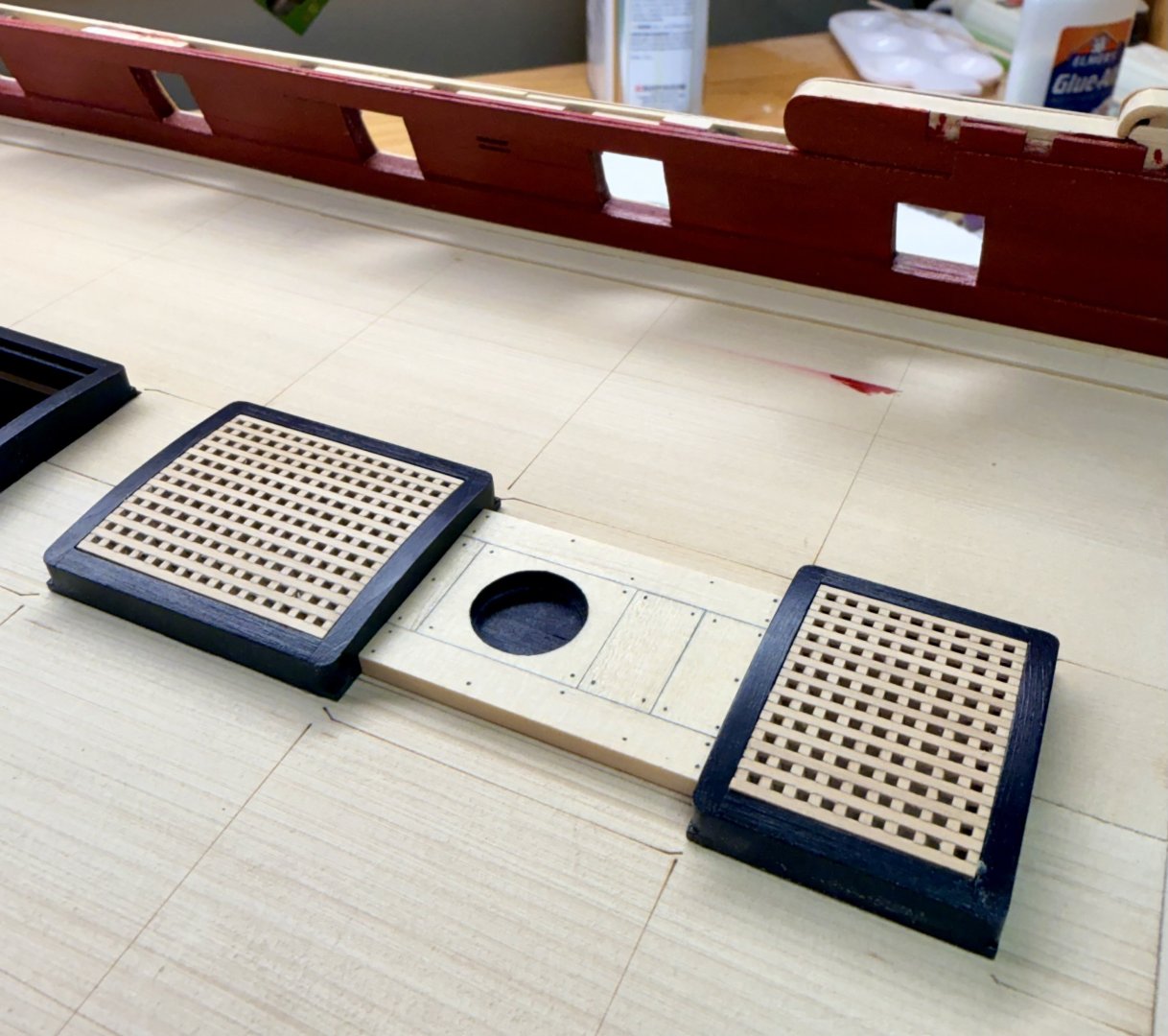
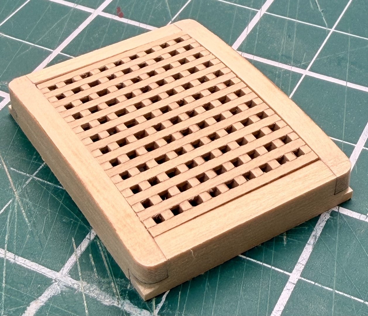
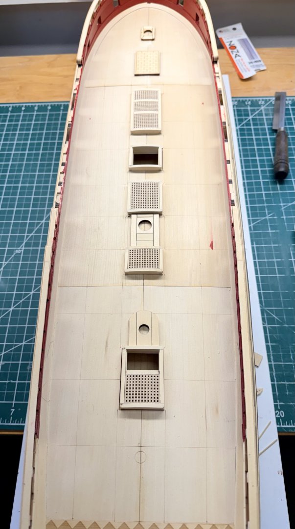
Once again, thank you for the comments and the likes. I've been on vacation the past 2 weeks and have been enjoying some time on my project now that the holidays are done. Another incremental update. I have the coamings and gratings all done and have the partners assembled. Had a little assembly line going on the coamings, I think they turned out well. There are a couple small defects in the spacing on the gratings but nothing that will keep me up at night. Just following the instructions in the chapter and no surprises. At this point, the partners were not assembled and the pieces were just set in approximate position. And a couple pictures showing the painted coamings and the assembled partners. Several thin coats of black on the coamings so some of the structure still shows. For the partners, I colored both mating surfaces with pencil to give a stronger caulking line between these pieces. Next steps are to add the bolts to the partners, and add the base colors to the stove baseplate. I'm going with the slate grey for the stones and black for the iron surround on the stove baseplate. Everything is still dry fit until I have all the pieces ready to permanently mount. Steve

-
Part II of update. Some pictures of completed work. Next up are the coamings. Steve

.thumb.jpeg.b6e8e140ca581baf92f7a0af7b4dd7ac.jpeg)
-
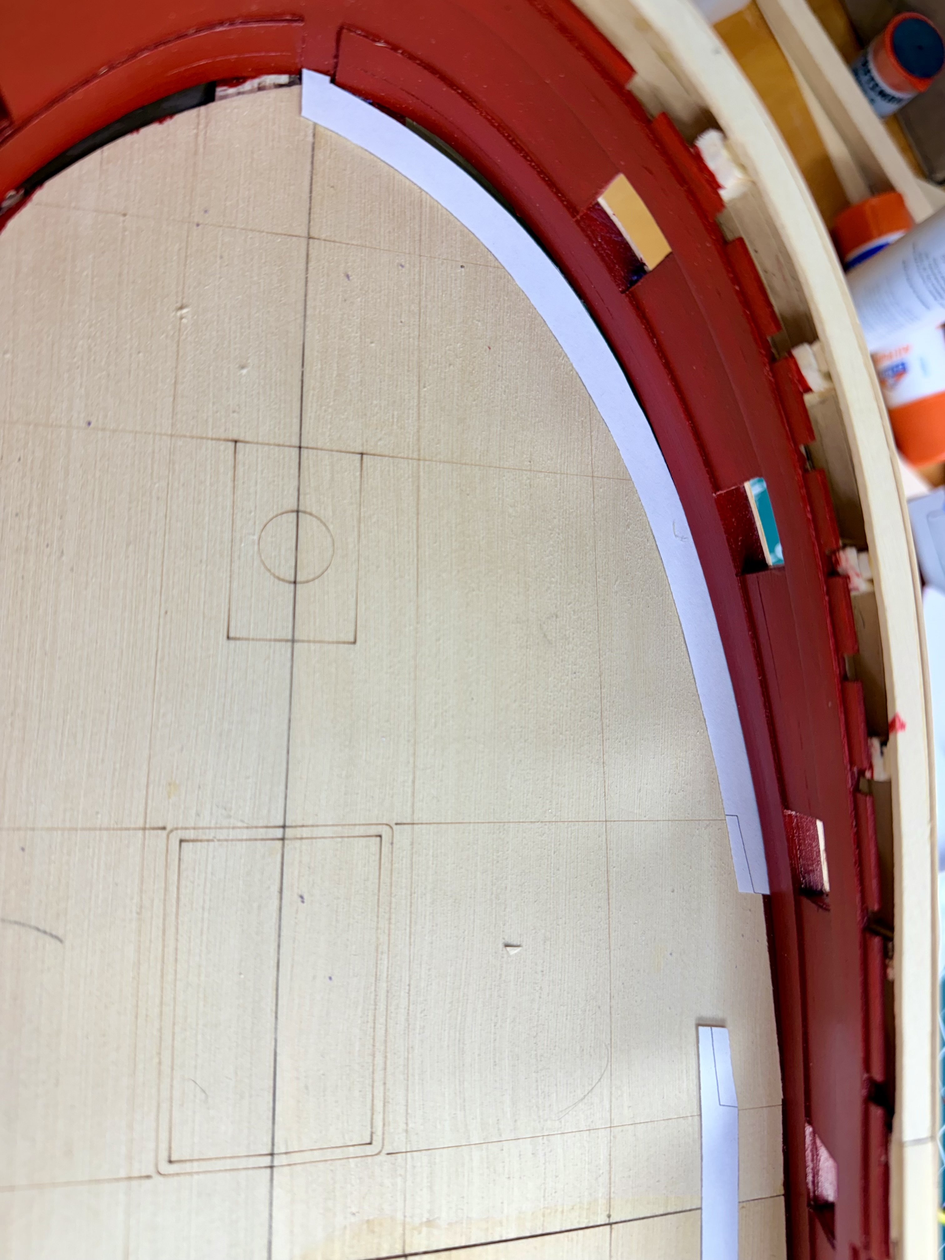
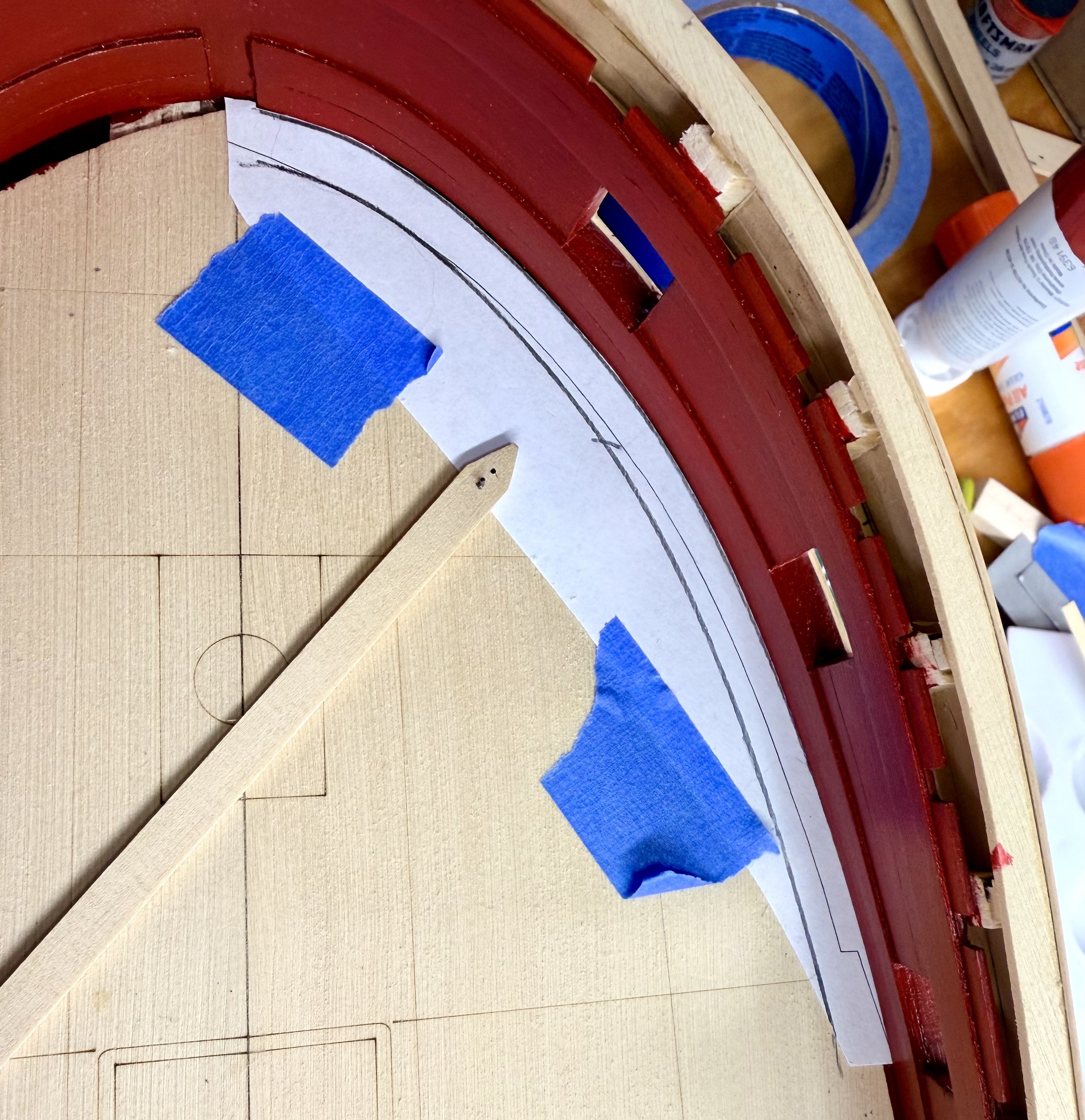
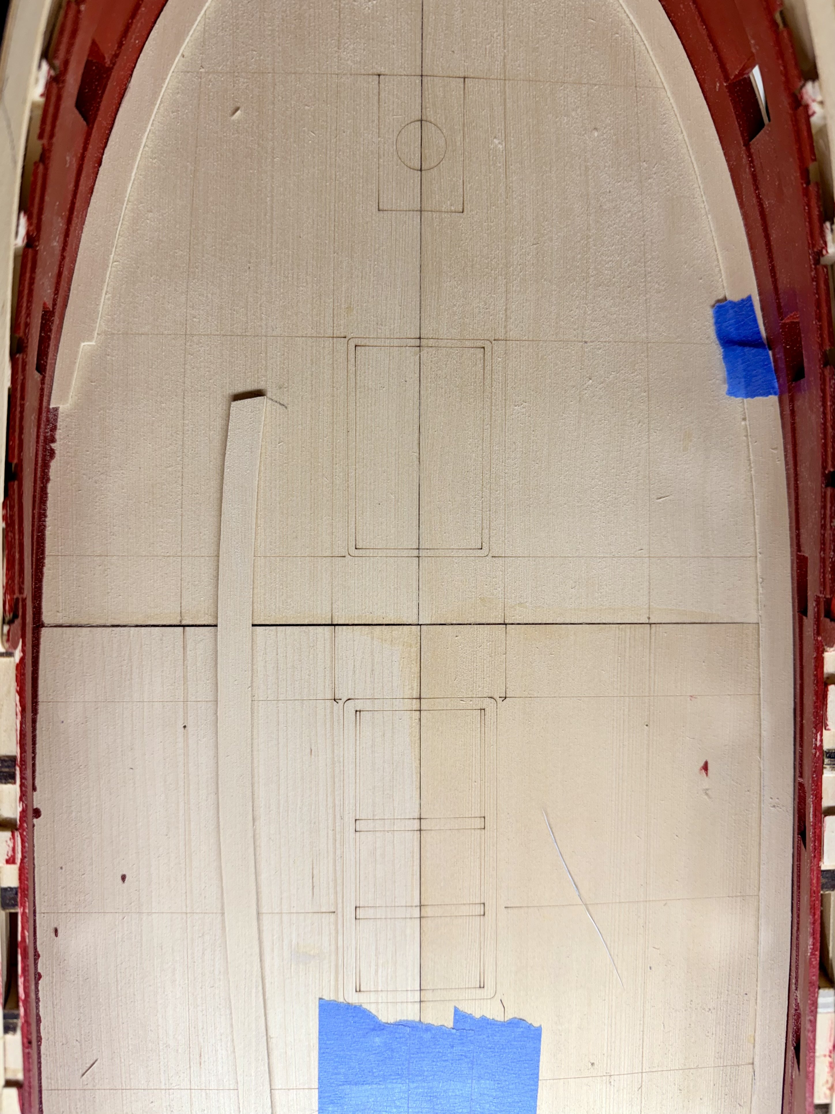
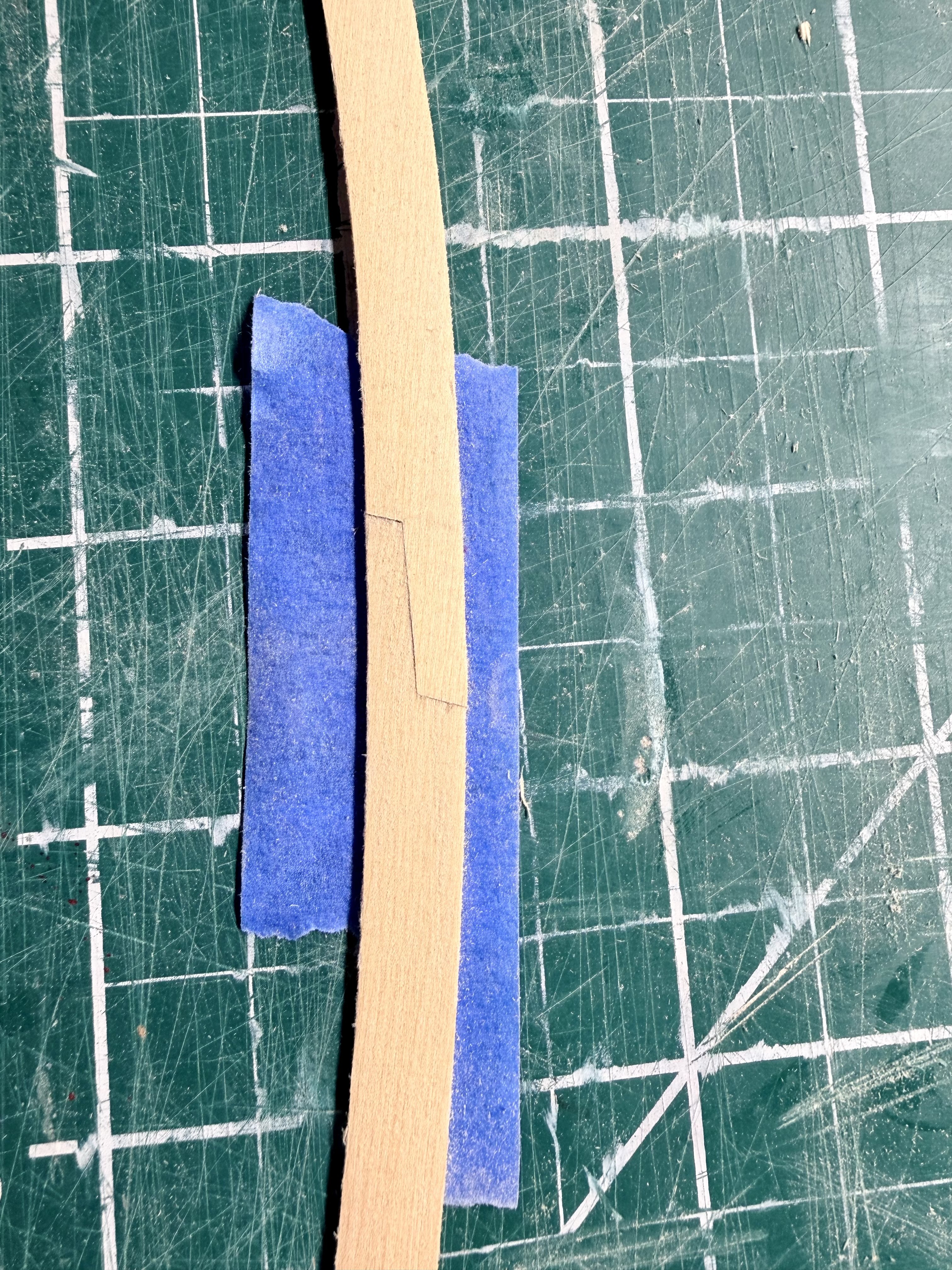
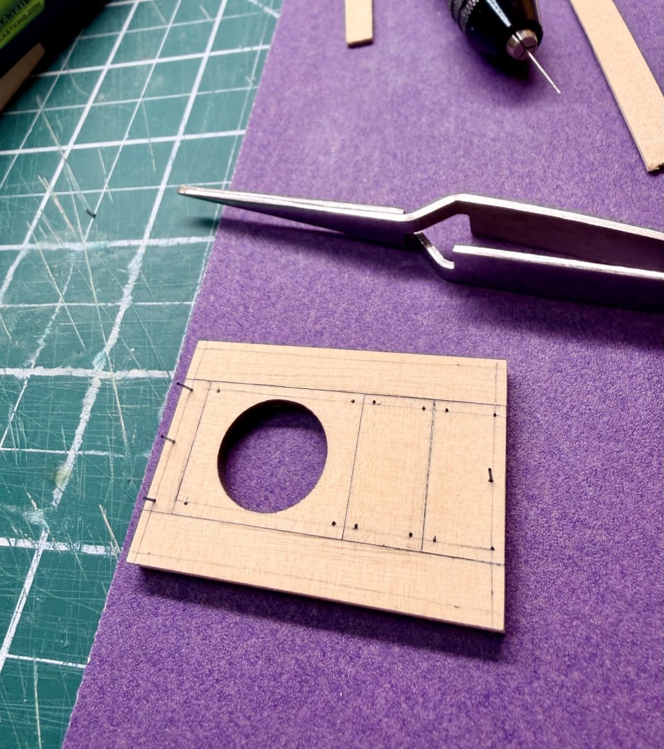
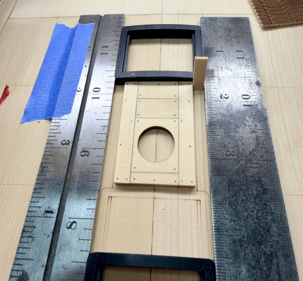
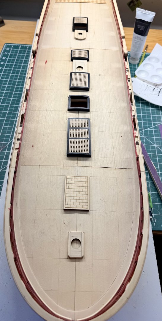
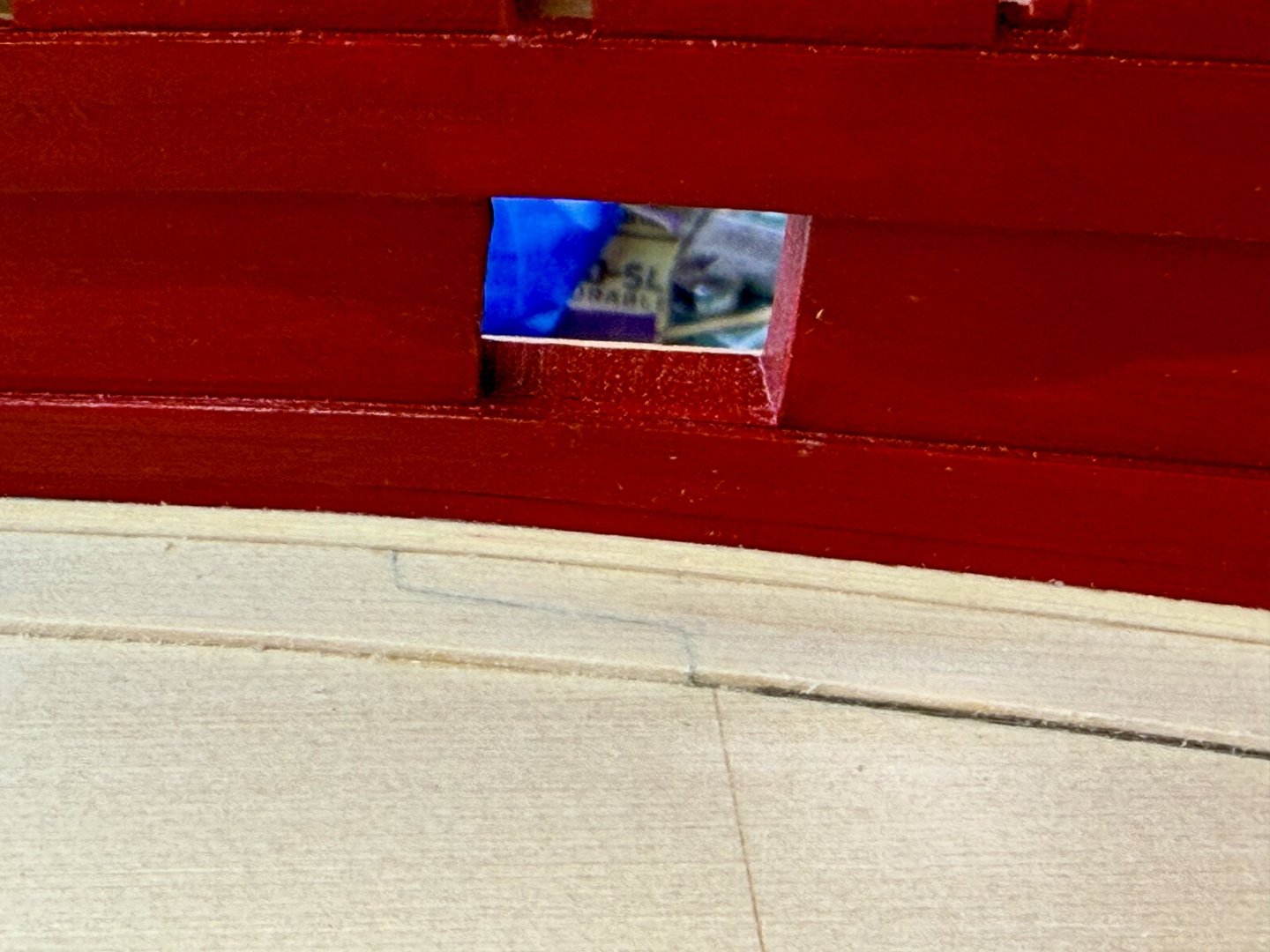
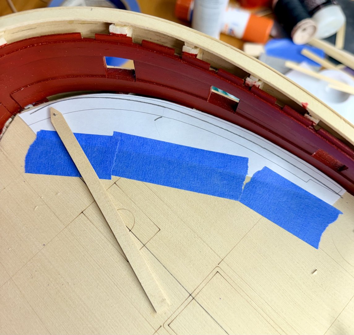
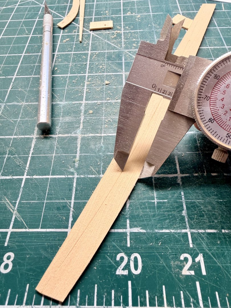
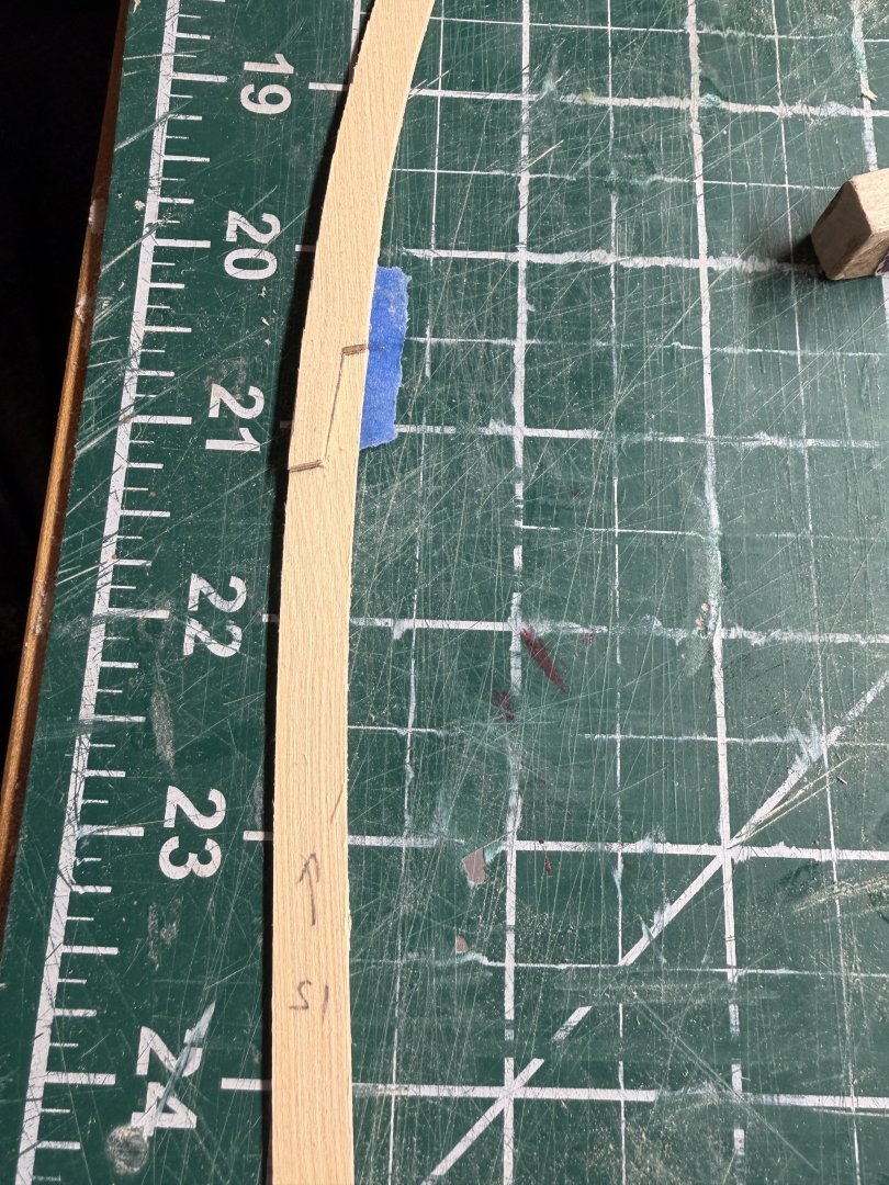
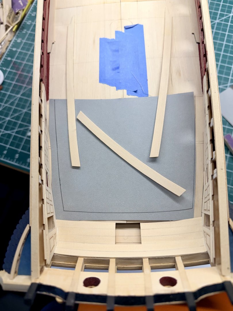
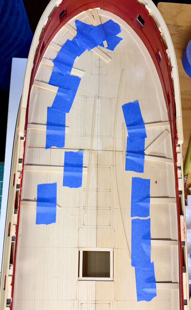
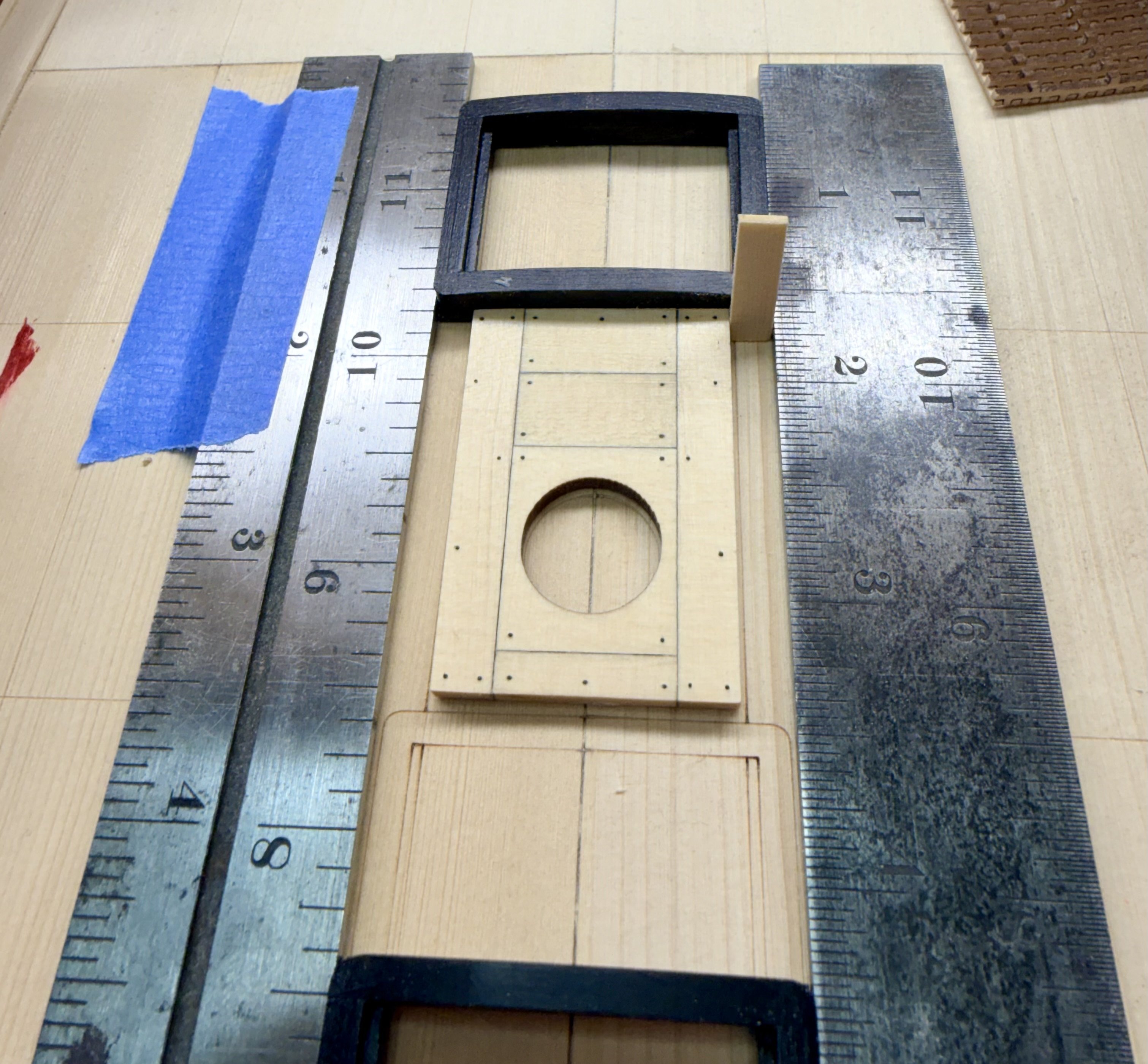
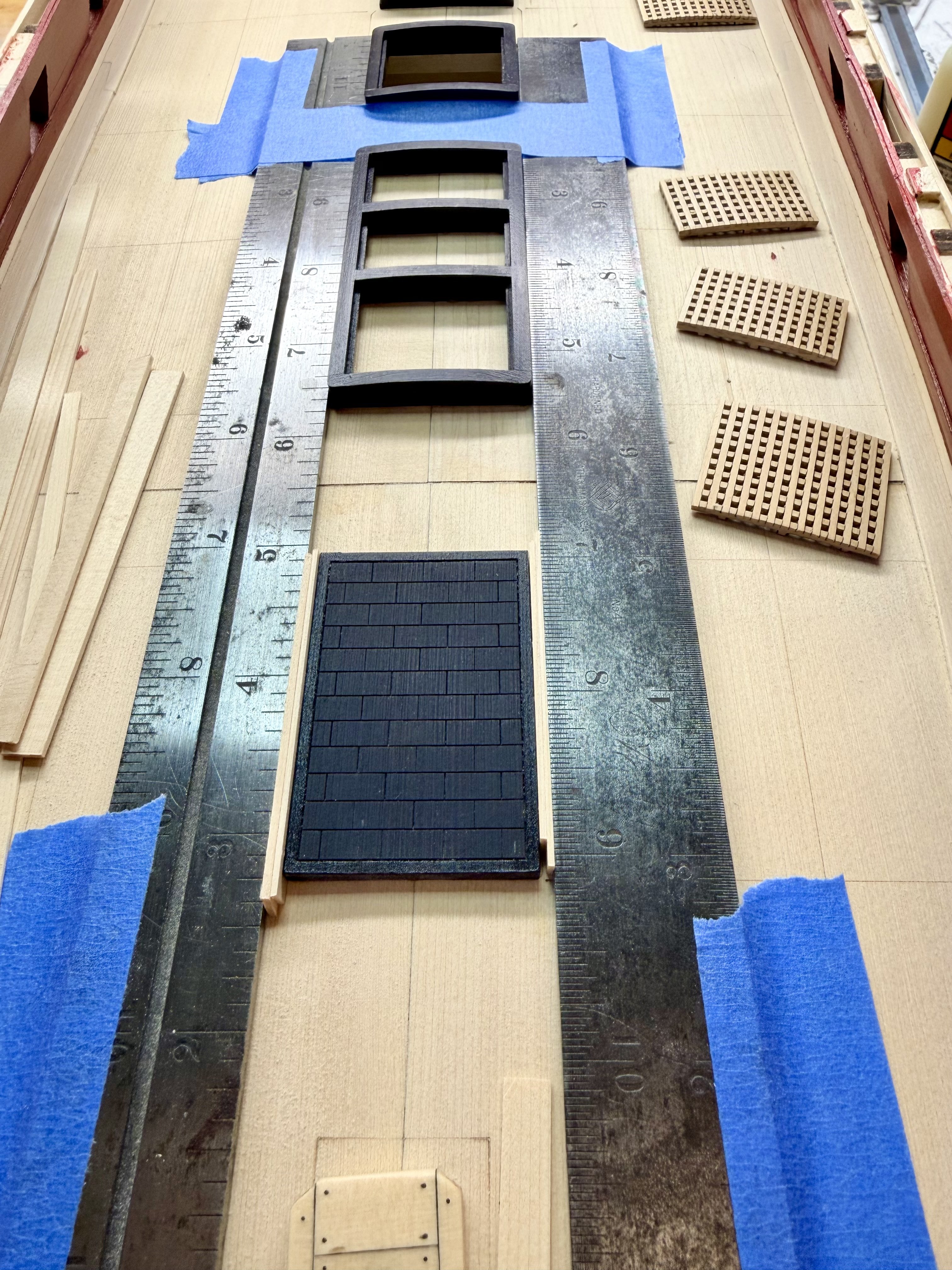
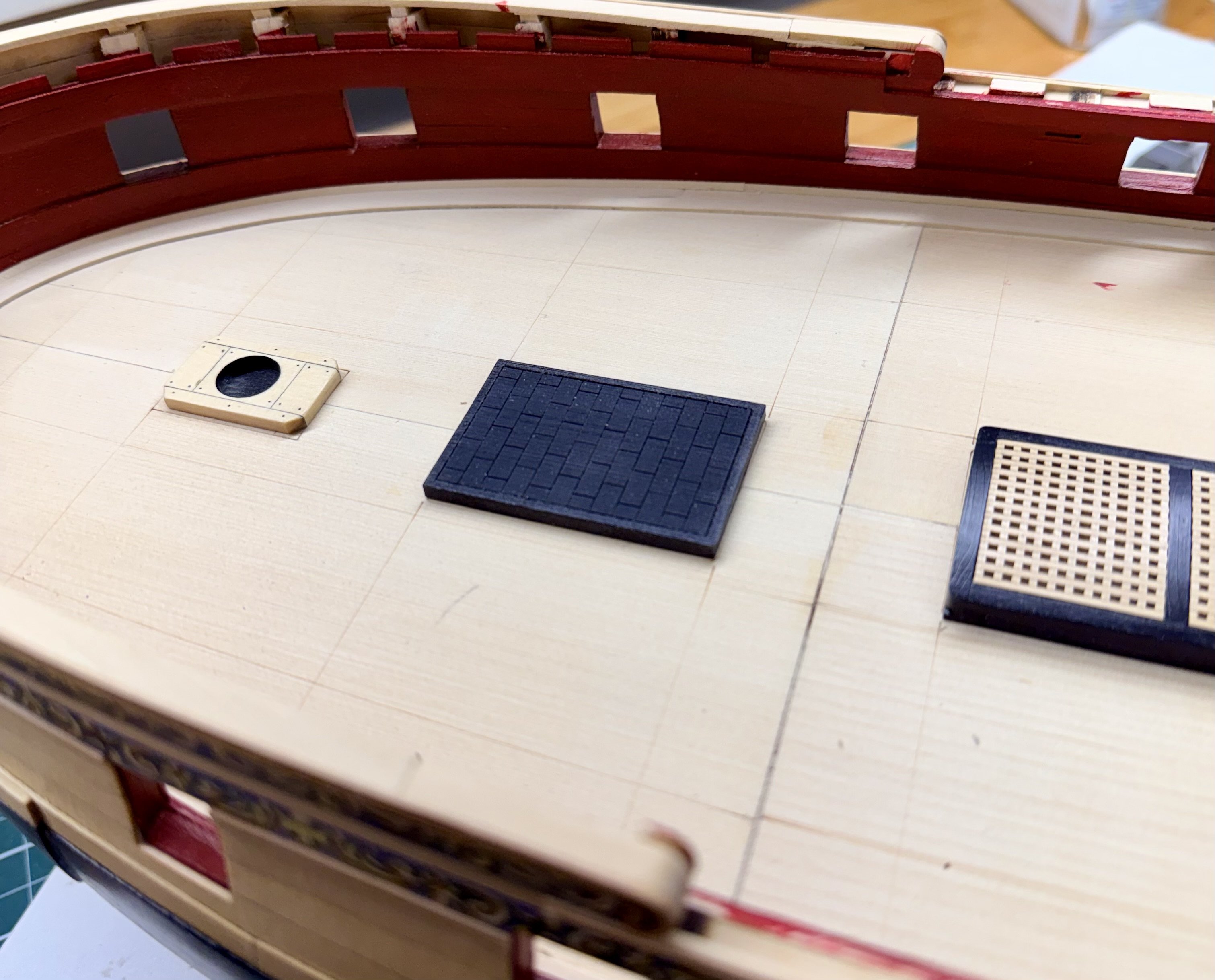
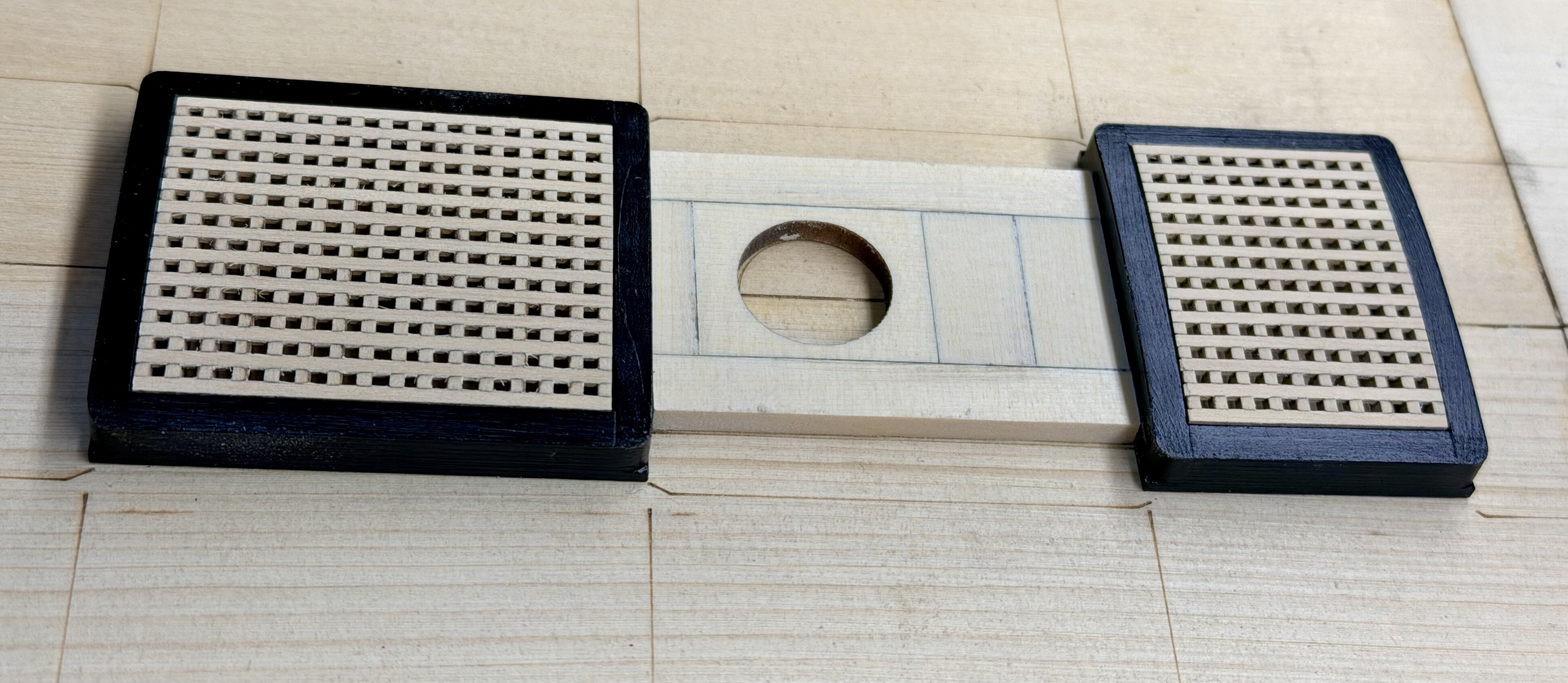
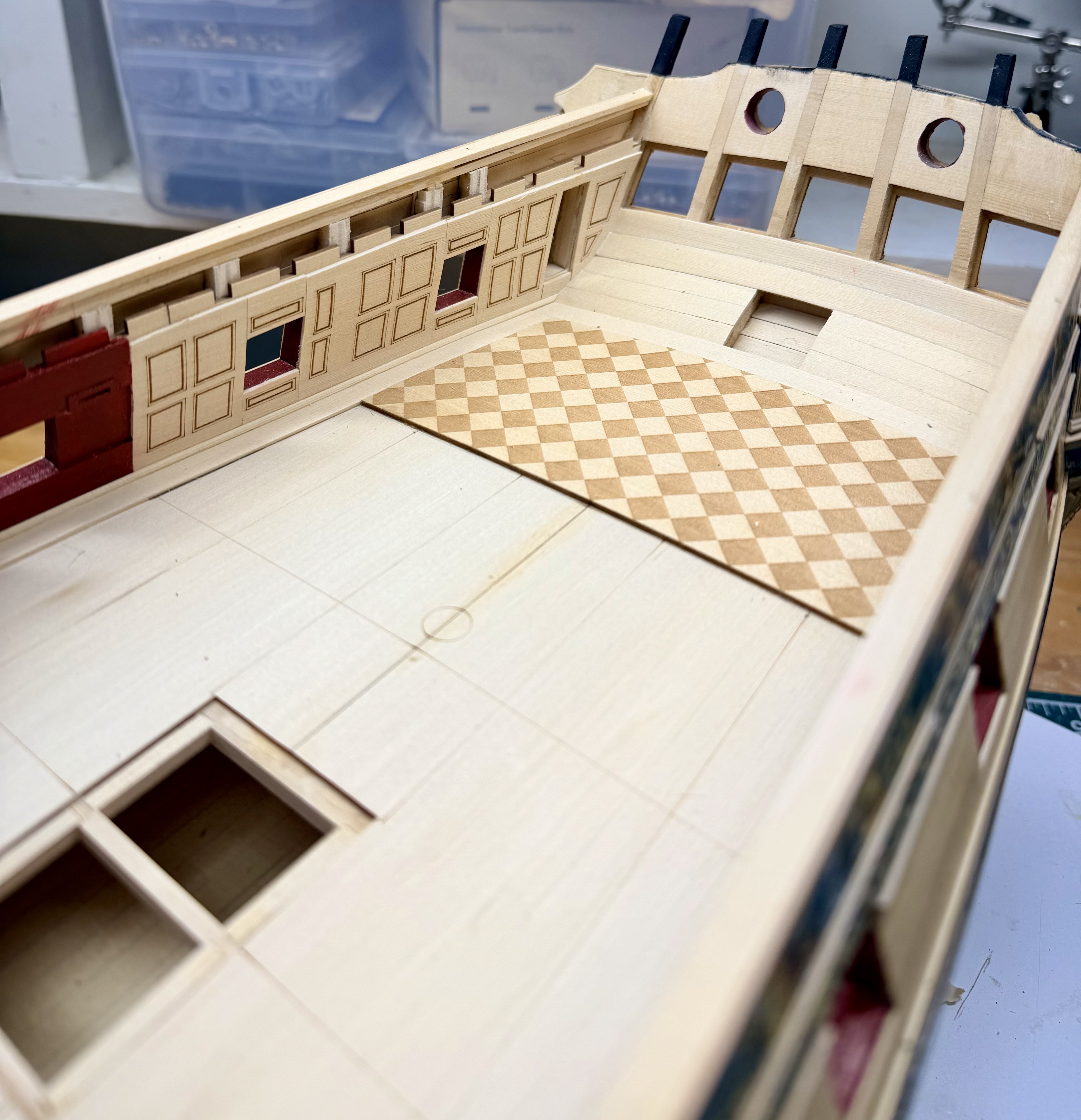
@FrankWouts @scrubbyj427 - Thanks for the comments, I am enjoying the progress in this chapter and trying out a few new techniques as shown below. A bit of a larger update today. I completed the margin planks, the waterway, and the checkered cabin floor. The margin plank templates for the bow were far enough off that they didn't do me much good. The curve of the bow on my model is noticeably more rounded than the templates. So I needed to make new templates for the bow. First I scribed a line following the curve of the inboard bulwarks using a stick with a piece of pencil lead pressed into a hole I drilled. Need to keep the stick perpendicular to the curve of the bulwark as you scribe the line. Then cut out the new template's outer curve, placed it on the deck, and scribed the inboard line after adjusting the location of the pencil lead in the stick. I cut out the port and starboard margin planks extra wide and shaped them to fit the hull, then used my calipers to scribe a line down each plank to create the inboard lines of the planks. I took the advice of a few different build logs and started the scarph joints at the bow working aft. I cut out one side of the scarph joint and then placed the margin planks back on the deck and overlayed the mating plank in position and taped them together. Then lifted the two off the deck and used the forward portion of the joint as the template for the aft portion at each location. Finished scarph joint with no gaps. Before gluing down the margin planks I made a template for the checked portion of the deck. Not shown in the picture, but I also marked the centerline of the deck on the template and then cut the checkered deck to rough shape before starting the fine adjustment and fitting. For the waterway strips, I made a jig by filing a notch into a piece of scrap material to position the 3/32 inch square stock at the correct orientation so I could sand the diagonal face flat. The cedar is too soft to get a clean surface from a scraper so I used a sanding stick to take off most of the material and then drew the stock through the jig while holding progressively finer sandpaper on it to finish the shaping. "Clamping" the waterway strips into position. They are so thin that not much force is needed so taping sticks onto the deck worked well.


.jpeg.85e220529f11bb1f126fb40035df58b7.jpeg)