

Jeronimo
-
Posts
729 -
Joined
-
Last visited
Reputation Activity
-


-
-
Jeronimo reacted to Trussben in HMS Pegasus 1776 by Trussben - 1:48 - Swan-class sloop based on TFFM
Now I’m trying to figure out the layout for the stern, I see that I do need to do a bit of fairing to the outer counter Timbers to make them and the inner framing a little thinner.
-
Jeronimo reacted to Trussben in HMS Pegasus 1776 by Trussben - 1:48 - Swan-class sloop based on TFFM
Thanks for the likes and nice comments.
Upper deck framing is now completed.
Next steps will be the waterways, port stops, bulwark planking up to the next deck clamps and then the stern framing.
I also have to start thinking/designing how much of the upper deck will be planked and how much I will leave open so the framing and lower deck can be seen.
ben
-
-
-
-
-
-
 Jeronimo reacted to DORIS in HMS ROYAL KATHERINE 1664 by Doris - 1/55 - CARD
Dear colleagues and friends,
Thank you all very much for your comments, kind words and support. It means a lot to me and I am pleased that you like the Royal Katherine model in my rendition.
It was a really great challenge when I decided four years ago whether to go for it or not, but despite many difficulties during the building, I do not regret this decision. At the same time, I fulfilled another modeling dream, which I was able to share with you and almost to the end with my husband George. The realisation of this project brought me not only the joy of the hobby itself, but also learning and possibility of expanding the knowledge horizons about real ships, their construction and history.
My main intention was to strive for the most realistic model reconstruction of the real appearance of the Royal Katherine and to point out the various shortcomings and inaccuracies that we often encounter in documents and plans of sailboat models. In addition, I tried to create my model without the use of special tools and from the most available materials as an example of the fact that even a very modest background is not an obstacle to creating a nice and quality model, which makes this hobby available to almost everyone.
None of us can know what the future will bring, but I definitely do not want to give up my hobbies and when I find enthusiasm for a new and interesting project again, I will share it with you.
Kind regards and all the best,
Doris
-

-
-
-
Jeronimo got a reaction from Archi in LE BONHOMME RICHARD by Jeronimo - FINISHED
Hello,
Foremast, Foretop, Bibbs, Rubbing-paunch
Karl
T e i l 23
-
Jeronimo got a reaction from Archi in LE BONHOMME RICHARD by Jeronimo - FINISHED
Hello .
Changing the anchor lines nodes,
according suggestion for improvement by Gerard Delacroix.
Karl
-
Jeronimo reacted to SJSoane in HMS Bellona 1760 by SJSoane - Scale 1:64 - English 74-gun - as designed
Thanks so much, Gary, Marc and druxey, for your kind thoughts. Gary, I have sent you a PM about drawings. Marc, like you, I love working through problems and finding solutions. I am glad you find mine interesting, because I enjoy looking over your solutions to historic accuracy.
And druxey, as you know, the projection drawings on the catheads are particularly fun, since they have to be adjusted first from true elevation to apparent plan, and then from the apparent plan to an apparent elevation to account for the stive in two directions. I confess it took me a few tries before I could visualize what was going on. I tried at first to work this in one step rather than two, but it was too complex for my poor imagination. I guess one step at a time keeps things more orderly!
Here is the cat beam fitted but not yet installed. Facing the prospect of many more beams to install on 3 more decks, I decided to rationalize the work a little.
I use my sliding jig to measure the distance at each beam between the sides. The next challenge is to trim each end equally so the centerline remains on center. I made a simple jig seen here, in which I can position the sliding measuring jig between converging strips of wood, and mark the location on the paper.
Removing the side strips of wood, I can then align the center line of the beam with the centerline of the jig, showing me exactly how much to trim on each end to remain symmetrical:
The cat beam interacts with the complex reverse tumblehome at the bow, and so its top surface aligns at an angle less obtuse than the lower surface. I used angle gauges to determine the top angle, and then progressively filed the lower surface through trial and error.
So now the first transverse piece at the bow, which will serve as the foundation for the entire beakhead bulkhead. It was very gratifying to see that the hull form I had constructed so many years ago aligned perfectly with where it needed to be in order for the cat beam to fit properly.
Next, thinking about the catheads and how they will cut through the bulwarks. I wish I had thought about this before already installing the sheer trim that will be cut into at the base of the cathead. Some precision surgery needed to keep this intersection clean.
Mark
Mark
-
Jeronimo reacted to Bitao in NAIAD 1797 by Bitao - 1:60
In order to locate accurately, the main beam of the back half of the upper deck is laid (not yet glued) . It provides a reliable guarantee for the smooth completion of all the internals in the later period.
-
-
-
-
Jeronimo reacted to Bitao in NAIAD 1797 by Bitao - 1:60
Finish the top deck beam machining. Using waterproof latex bonding, interface to do a black line treatment to increase the effect. Use for at least 48 hours after the hot bending treatment. I can have a rest these days.
-
Jeronimo reacted to Bitao in NAIAD 1797 by Bitao - 1:60
Due to my very limited knowledge, and may not have a good understanding of ED drawings and design concepts and instructions, resulting in the previous completed with the chain pump connected to the“Axis tree” manufacturing error. I may have“Simplified” it for a lot of people. Thanks to Greg for correcting this in time and providing me with detailed drawings that gave me an intuitive understanding of their basic structure. His rigorous attitude and the spirit of unremitting pursuit again let me admire unceasingly! This made me decide that I had to scrap the original result and re-make this part, even though it was considered perfect by many and liked it. Maybe the improvements you see now are still not perfect, but I have done my best. In my opinion, every outstanding person is trying to achieve every detail, it is this forum for everyone the biggest harvest. It's also a reality I have to face in order to make progress. Here, I have to thank each and every one of them for providing me with the information and correcting my mistakes. Thank you!
-
 Jeronimo got a reaction from FrankWouts in ROYAL CAROLINE 1749 by Doris - 1:40 - CARD
Hello Doris.
Pictures of Ivan Trtanj and Royal Caroline.
Regards Karl
-
Jeronimo reacted to Kiyoo Iizawa in Making frame drawings and its adoption to laser cutting
Thank you for many comments.
Hi Mark P,
In fact, I have already prepared a step-by-step manual that explains the steps from learning software to actual creation work. It seems to be the best for learning this method. Please wait until I finish writing this topic on how to make it open.
Hi jaager,
This is an easy and much faster drawing method as you say to create accurate shapes at scaled size, correction drawings according to various processing machines, etc.
The number of lines for inside shape is as good as 10 when creating the outer shape. Actually, the lines drawn with the outer shape are copied and shifted the control point inward by the thickness according to the height.
In case the laser machine I am using in rental shop, the data machine recognize can still be used in Illustrator format. Therefore, there is no malfunction due to conversion. As far as I know, laser cutters seem to be able to use 2D graphics data such as Illustrator, CorelDraw, etc. as they are.
If this can be said to be a development product, I want to have ownership. However, the purpose of my posting on this topic is because I want anyone to use this technology openly. I think there are some things that need to be addressed for that. I'm old enough.
At first, I was skeptical about the use of lasers, especially for scratch builds, but since the advantages are much greater than the disadvantages, I put them to practical use after considering how to avoid the disadvantages.
Workarounds will be described soon in this topic.
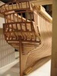
I actually designed a part equivalent to one structural model kit, processed it with laser cut, and am currently in building for verification. I have cut over 1,500pcs of parts within 8 hours. This picture is hull made parts by laser cut (just lightly sanded to remove burn mark). Also the cross section that took out some of it is my thumbnail.
To evaluate this method, please read this topic until it is over. I hope it will meet your expectations.
Hi PietFriet,
I have no knowledge of Delftship at all, but I think it can be used if it is software with similar functionality to the 3D graphics software I use. It is a free-form surface creation function by Bezier curve and numerical control function for dimensions and coordinates.
Thanks again,
Kiyoo
-
Jeronimo reacted to Kiyoo Iizawa in Making frame drawings and its adoption to laser cutting
Hello everyone,
I am posting for the first time. Please forgive me for my uncertain English.
With regard to creating the precise 3D graphics images, I am far from Denis's amazing graphics in Swan class 3D modeling. However, using a similar 3D graphics software, my attempt here is to create line data, i.e. frame drawings, from that 3D curved surface.
Many 3D graphics software output formats are raster data, i.e. gathering of the small dots, but drawings such as CAD we use for part machining are consisting of vector data, i.e. line shapes represented by mathematical formulas. They are not compatible because they are completely different data.
But looking at the graphics image like below, wouldn't you wish to make each shape of this frame to an accurate drawings? It is the software that I am using that enables it. In other topics such as “JPG to CAD” are also being discussed this kinds of matter, but I think this method introducing here is also one of the way to do it.
If such an indefinite shape can be made into an accurate drawings, it is expected that drawings making and parts processing in scratch build will become much easier.
I would like to introduce the outline of this method by continuous posting. I wish you will be interested in this approach.
Because it is difficult for me to provide instant English sentence according to the situation, I am preparing outline description as a document. To identify the document part and the daily conversation, I use document text with green color so that you can easily pick up only the document part.