.jpg.f26acc9a74319261612561bfa7da1303.jpg)
vaddoc
-
Posts
1,605 -
Joined
-
Last visited
Content Type
Profiles
Forums
Gallery
Events
Everything posted by vaddoc
-
.thumb.jpg.6fd4c1b78768bb3efd745ab810936005.jpg) Many thanks all! @wmherbert have a look Bill https://www.amazon.co.uk/dp/B0BYT3J89B?ref_=ppx_hzsearch_conn_dt_b_fed_asin_title_2&th=1
Many thanks all! @wmherbert have a look Bill https://www.amazon.co.uk/dp/B0BYT3J89B?ref_=ppx_hzsearch_conn_dt_b_fed_asin_title_2&th=1 -
Dear all Many thanks for visiting, for your likes and comments. I ve done a lot of work on Tally Ho - shed buckets of digital sweat. The deeper I dig into the boat, the bigger respect I have for Leo and his crew for pulling this off - the complexity of building something like this does not really come out fully from his videos. So where to start... First a correction regarding the missing beam at the bow: Leo explains that there was actually a notch at the beam self that was however filled in - so the builders decided not to install this beam, probably to allow more space at the bow for activities. I also fixed a ripple in the hull midships that is visible at the previous photos - one of the frames was wrong. Now, no matter how much I tried I could not make the stem and sternpost as narrow as Leo's without deviating a lot from the plans and table of offsets. However, for the sternpost this is a problem. If I make it too wide, the frames will ride very high and the sternpost knee will be huge. If I make it as narrow as Leos, there is a tiny area at the stern were planking will be unsupported. So either I make the sternpost wide and trim almost all of it away which will be a huge job or add a very small filler piece - the second solution is much better and even a lot of this will be trimmed. With this sorted I arranged the bow and stern timbers. I followed Leo closely in his arrangement, almost all frames will be notched into the keel. All keel pockets will be milled before the keel goes in - I hope I will be able to pull this off as the keel will be monumentally huge. And it will have a 1 degree slope - somehow must be made. I then made the transom timbers and the transom itself - this took some head scratching. Note the aft most half beams - these will be fun to make... Then I made all the beams and carlings, including the one that is offset from the midline at the bow. There is a bit more work that needs to be done but they are mostly ready. I also made all the stanshions, I followed Leos arrangement pretty close but not quite - I arranged them to lie next to beams to help with placement during the build. I now need to make the beam self and figure out how far from the underside of deck it should be placed. This was a massive piece of work but I think now we should be ok to move on to the next stage. So now each frame needs to be extended and the deck slope marked - this will be where they will be trimmed in the end. All the frames need to be arranged on wood sheet patterns 1000 x 100 mm to figure out how much wood I ll need - times 2 as each frame is a double one. The deck beams will also need to be arranged in the same way. Same with bow and stern timbers. Same with hull that will be built up in several layers. The covering boards, bulwarks and deck planking will need to be calculated and of course the hull planking, the Transom as well. Adding wastage and considering the actual length of 1.2 m, this will be a massive quantity of wood, in multiple thicknesses. I will be using pear and cherry for the keel and frames, perhaps maple for the hull planking - or pear. I would like to use Alaskan yellow cedar for the deck but I do not think I can get this in the UK - perhaps Castelo then if I can get it in 1000mm strips/sheets. Perhaps mahogany for the deck structures. I do not think there is a modelling alternative for teak - I ll use cherry maybe. Considering how thick the timber will be, I thought a new toy is needed. It works great - highly recommended but no doubt I will also need the very expensive Proxon thicknesser - if I can get the Admiral to authorise the investment. Many thanks for visiting and Merry Christmas! Vaddoc

.thumb.png.c889ece2620885d5a368ab4e89bcaef4.png)
.thumb.png.39b591832685c520de9c2d383a4ac373.png)
.thumb.png.c883b271864c7db5a2b8574da7e5788c.png)
.thumb.png.6178058556804607c89ef2257d049ee9.png)
.thumb.png.46a7ca8727e250c57bffe3a516b284d8.png)
.thumb.png.3e1426452aff78b5b347be9f05770337.png)
-
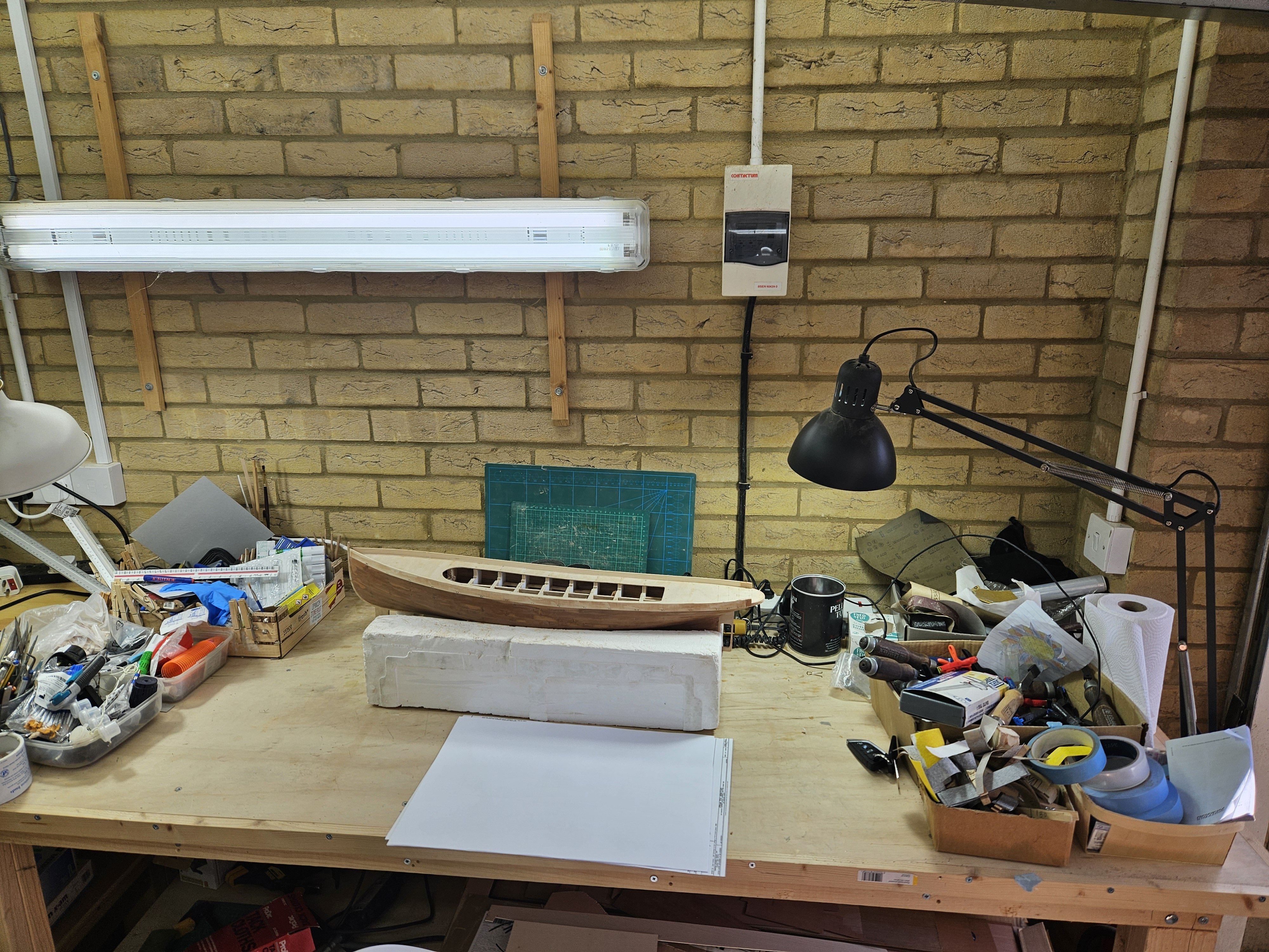
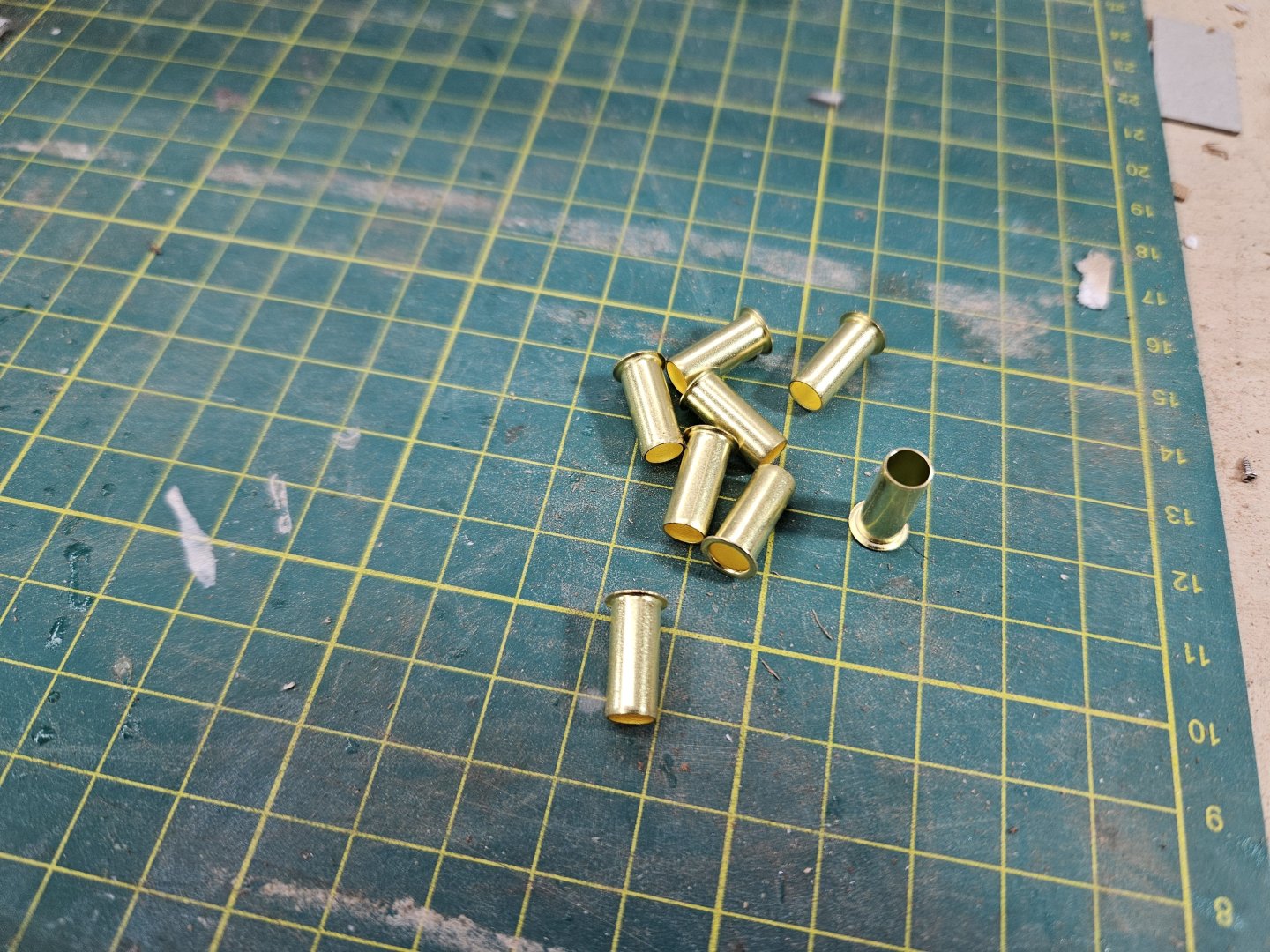
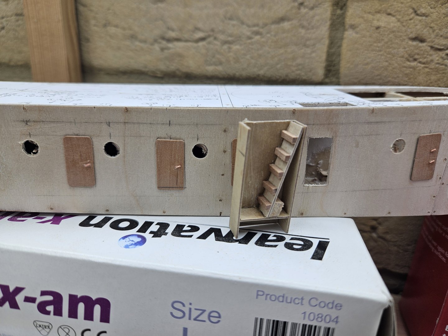
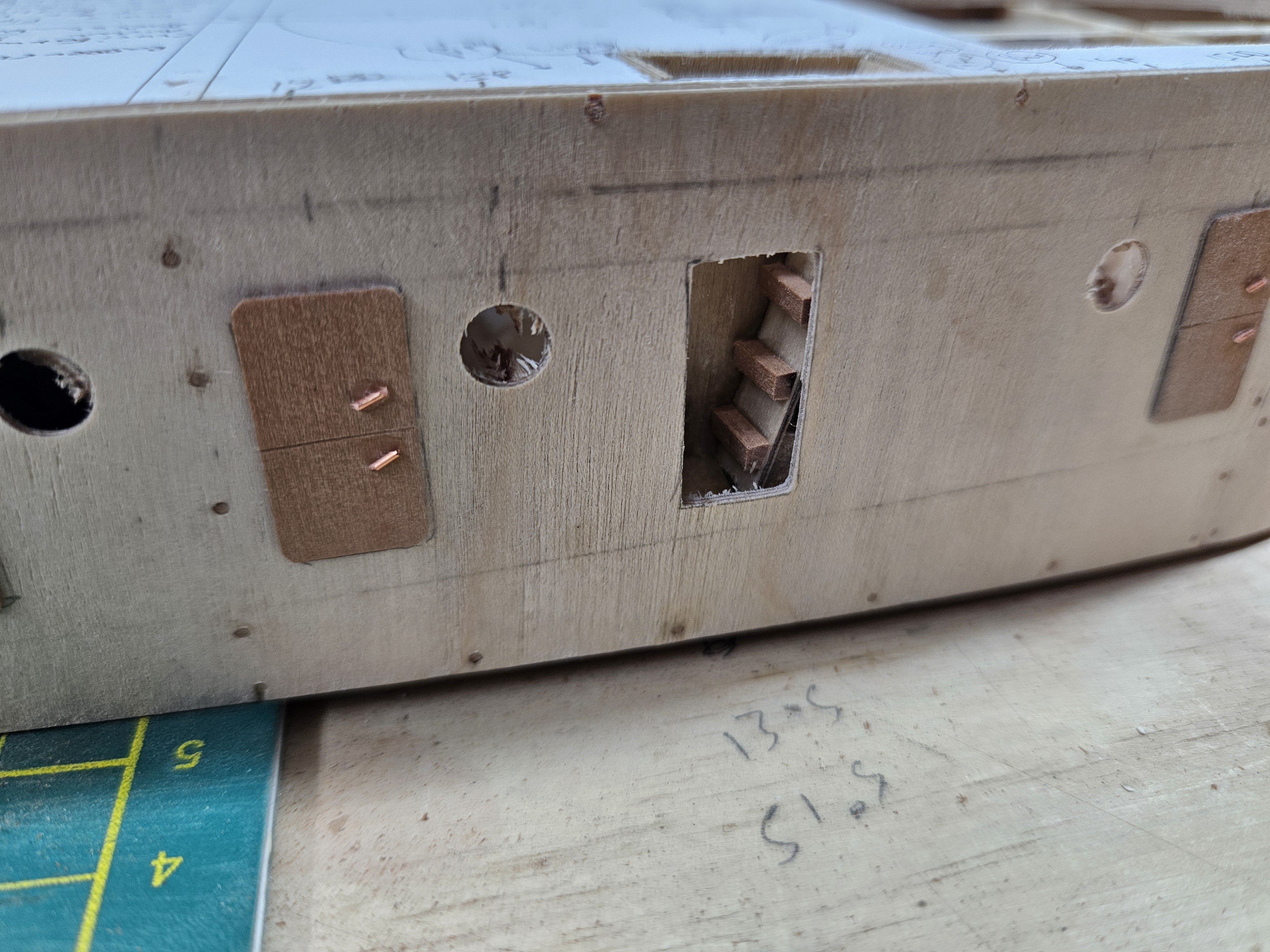
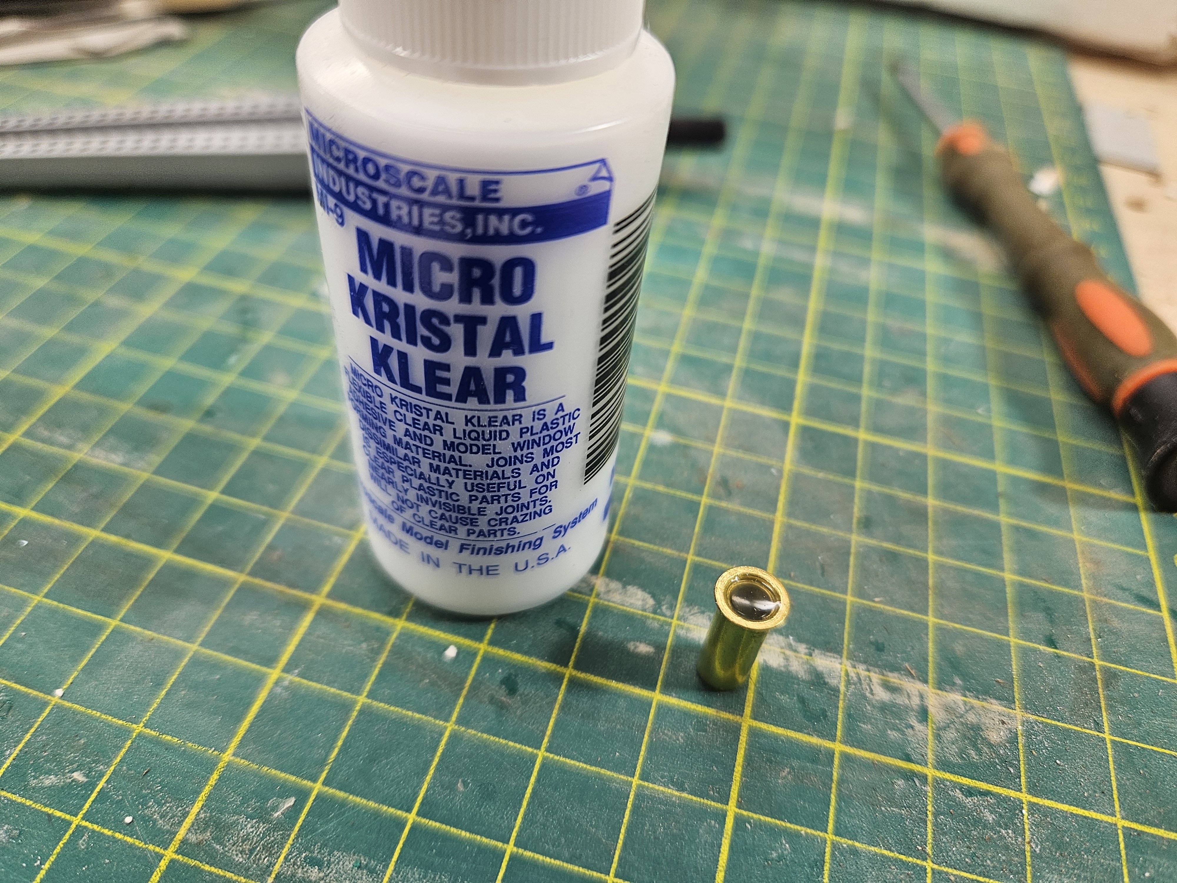
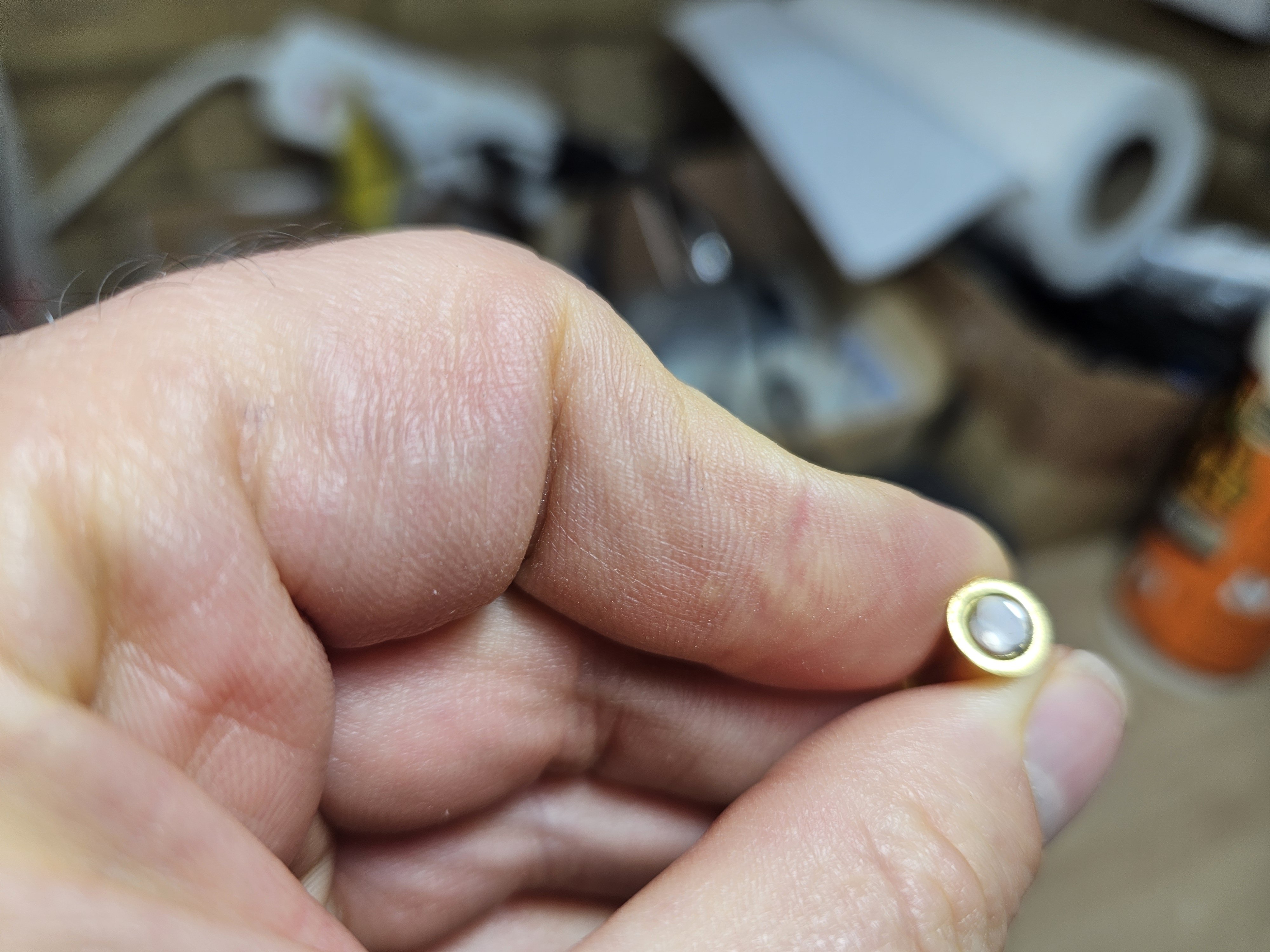
Dear all Time to revive this log! @KeithAug Lol, no, no long vacation, just very limited time and almost all of it taken up by Tally Ho! Ok, so I did a bit of work on Hercules. I managed to finish the timber guard at the stern which was a bit tricky, I am not used to work at such small scales. I then installed the lower timber guard Then I started work on the first level of the superstructure, lots of things going on there. I made the doors and drilled (very carefully!) the holes for the portholes- it was at that time I realised there is a staircase. After a bit of trial and error I managed to come up with something that painted black will look ok ish I think. For the portholes I just bought cheap brass plumbing thingies that come in all dimensions. I experimented with Micro Kristal Clear for the glazing - excellent results. I then made the cap rails, I used mahogany which is the wrong wood for the job but did not have anything else in 1.5 mm thickness and I am not ready to put in the massive wood order for Tally Ho. Everything will be painted black though so should be OK. I also made the stern structures and roller - All need to be painted and screws replaced with wood nails. I then made the quarter bitts - still need a bit more work though Really now it is time to paint the hull and make and paint the rudder so I know where exactly the steering mechanism at the stern needs to be placed. It is too cold though in the garage to spray primers and I do not really have permission from the Admiral for indoor modelling activities - or actually the time. Still Hercules seems to be on the right track steaming along side Tally Ho. Many thanks for visiting Vaddoc


-
What a beautiful model Brian! Indeed an inspiring journey, Cairo was also a great source of ideas. Very well done, your logs are a joy to read. Vaddoc
-
Previously Elmers colour changing filler but this seems to have disappeared in UK. Now I use Osmo filler, water based, dries very fast. The 100 ml is very runny, the 250 ml needs thinning to whatever consistency needed.
-
Dear all Since my last post lots of things happened, basically I had to scrap everything - again! @AntonyUK Thanks Antony, I am silently following your log, she is coming along fine - lightning fast progress as well! Ok, so here is what happened. I was happy with things but then I started work on the sternpost and this is when I realised that my hull was wrong. The sternpost is a solid piece of timber with a set thickness. The inner skin of the hull needs to meet it in a certain way so that the frames, which follow the inner skin, can be bolted onto the sternpost. The way my hull was lofted was too wide at the top so that it did not meet the sternpost, but also too narrow near the bottom so that the frames would need to be positioned too high to be bolted on to the sternpost. So, it was clear that I had to reloft the boat but first roughly arrange the sternpost. So, back to Leos videos. Using this (and others) image, where all lines are shown, I was able to recreate his sternpost. Then I relofted the boat. This time I did 4 cycles, for modelling purposes I do not think I needed to do any more. I also decided to keep the 1 degree slope of the keel. And with the rabet and transom Compared to Leo's hull, it looks pretty close - of course the shape will be a bit different but not by much How about the sternpost? It actually is fine. The next photo shows the hull somewhere in the early stages of lofting. The shape of the sternpost can be seen, the lower line is where the outer skin meets the hull, the upper one where the inner skin meets it. Obviously it looks wrong This is how it looks on the finished hull - much nicer, lots of timber for the frames to notch, I can also change the shape of the sternpost a bit. But a boat has two ends - what about the bow? This also has a set dimension along its length. The hull is lofted to the face of the stem but the planks will end at the rabet which is vertical along the side of the stem, but its projection to the side of the hull is not. It's ok though because this difference is very small. I started work on the stem assembly, again following Leo's arrangement But I could not make it work, the rabet would not transition smoothly from the stem to the keel. I struggled for a few days until I realised that my rabet was all wrong. When I fixed it, it all came together. If you are lofting this boat, the rabet must pass through the point where the underside of stem meets the upper surface of the keel. Still, my stem arrangement is not correct - it is not thick enough. In station No1 there is a frame and from there aft a frame every foot. My stem is not thick enough for the frames to be bolted on. This is easily corrected. One last issue was at the stern, I had the impression that in the plans there is one additional frame. The next photo shows why this is not the case - there is simply no space for it. I am aware these are very boring posts but please bare with me - this is not an easy boat. There will be lots of saw dust in the future! More work is needed for the frames, bulwarks, beams, deck planks etc, this is also to be able to figure out what wood I need to order - it will be a lot! Till next time, take care all Vaddoc


.thumb.png.8d65c49f89bdb291c493eeca57764fce.png)
.thumb.png.5b9495b6d25d83d50dfe1dd80972d0f8.png)
.thumb.png.26a08bdea35b8b7faa59f3359361642b.png)
.thumb.png.2022d7cd7acc28faf8ac0ffcc442d1a3.png)
.thumb.png.5141fa1a41e3dff5f43ca878322f8bce.png)
.thumb.png.314bf6ffa2beb75b4937d8dd3995a54c.png)
.thumb.png.8460f35aa4e7ee24cad3b602d74471f8.png)
.thumb.png.a86e9bd48806b0344998fbbea9be4274.png)
.thumb.png.58fcfbf820a064818fb13b6506b1ce71.png)
.thumb.png.d6cee812075b451c1d6c8cdf73ba2b37.png)
-
You are very right, just teasing you a bit! Lines and offsets are in reality just rough guides. In the end the wood will correct things with a few sims here and there.
-
Many thanks to all for visiting, commenting and hitting the like button. I cannot resist a special mention to @Bedford: This is a boat built without these calculations. Lava chicken anyone? Now, I know these posts are boring and probably difficult to understand but I have been diving deep into this hull and I think is best to post my progress as I go, maybe it will be of use to others in the future that may want to build a similar boat. There are so many things going on and defining the various aspects and parts of the hull need to progress almost in parallel. You may be working on the keel and frames but then the deck needs defining which means the bulwarks need defining but then the transom needs sorting and so on. I can understand Leo when he was saying how complex it was building Tally Ho. Back to the boat now: I ‘ve been studying Leo’s videos and they are a treasure of information. He posted this picture of the lines of the boat. I compared it to my lines and they are not far off. His bow is a bit more narrow, this is why his stem is 7 inches wide and mine is 8.8”. I do not know how he did it – I absolutely could not make it work without deviating too much from the plans Perhaps I followed more closely the table of offsets, whereas he seems to have followed more the lines drawing – but he had the boat! Up to this part, it would have actually been easier to use batons to fair the curves. But from now on, CAD really shines. So, up to now, we have the lines of the hull, the keel, stem, sternpost and transom to the OUTSIDE of the hull. We now need however to define the INNER surface of the hull, where the frames will touch. This is extremely easy with CAD, just a command to offset the surface. The thickness of the planking is 1”3/8 to ½” but I made it 3mm to help with the build. Now, using the inner skin, we can define the actual width and shape of the transom, as the initial shape included the thickness of the planking. Now, we need the frames. Leo changed the thickness and made them all double frames. Projecting vertical lines on the inner skin gives us all the frames with all the outer bevels. We can then offset the inner skin even further to the thickness of the frames and do the same so now we have the inner surface of the frames with all bevels ready. I started work on finalizing the frames. They rest on the top of the keel but also there is a pocket on the side of the keel where they slot in. So I decided to do the same. Leo mentions there is 1 degree slope to the keel but mine is dead flat. The pockets will also be parallel to the midline, they will not follow the curvature of the hull However, after a few frames I stopped. To define the upper end of the frames, the deck had to be made which means I had to decide the camper, that is the amount of lateral curvature of the deck. This needed a bit of head scratching. My experience has been that the camper is fixed and applying it along the sheer, gives us a curvature that gently transitions from zero fore and aft to maximum in the middle. However, Leo did not do this. He very usefully has posted this photo. There is still camper even at the transom. So I shamelessly copied the curvature of his deck form the profile view and asked CAD to create a surface. Now, this was offset to account for the thickness of the deck planking and that gave us the inner skin of the deck It should not be difficult to find the shape of the beams later on. So now there is a new sheer to account for the thickness of deck, this will also be used to trim the top of the frames But now, it is time to deal with the bulwarks and the stanchions. Leo seems to have spend some time on this and it has been on my mind but it went very smoothly. So the stanchions are additional pieces of wood that extend above the deck, hold planks and create the sides. Again, Leo very usefully has posted a drawing of the “sheer” of his bulwarks. This is a very interesting part of the boat. The bulwarks from the profile view follow the actual sheer. From the top view however, their "sheer" crosses the boat sheer again and again. I am not sure how exactly it is defined and what implications the different angles have but again I copied Leo's . It looks ok and I do not think I am far off So, now that this “sheer” is defined, it is easy to ask the computer to create the surface and offset this to get the inner skin. The stanchions can easily be created in the same way as the frames. There is an interesting element where the bulwarks meet the transom. This will be a particularly tricky area especially when the toprail will go on. Ok, so far all is going well. Next the bow timbers will need to be defined, I will try and follow Leo’s arrangement. Then will be the sternpost. Then to finish all the frames, arrange the transom timbers and then the beam shelf and all beams. Regarding the beams, Leo has followed exactly Mr Strange’s arrangement except for an area in the bow, there was a wide companionway but he reduced the opening and put in an additional beam. Regarding wood: I think it will be pear for keel, frames beams etc, maple or pear for planks, boxwood for deck, perhaps mahogany for deck structures. Leo used Teak for the covering boards, I may use cherry or pear for this and also for the stanchions, bulwarks and toprail. I think some suppliers provide iroko which has similar colour to teak, I have no idea if it is any good for modeling. One thing's for sure, the wood order will be massive. You were warned this would be long and boring! Many thanks for visiting Vaddoc
.thumb.png.b917a8770f40e9deb4922abd04e21d17.png)
.thumb.png.8eb1c9ceae201e1df768a0a33bad2e9c.png)
.png.13c8326d98711a00cfeb89b38ac27d59.png)
.thumb.png.774bbf38cd56d426a4b92cd25eede3c1.png)
.thumb.png.addc8ba0aacf9a863f376ba2cfe0eb4c.png)
.thumb.png.01e33def061569d467edcb4a548586d8.png)
.thumb.png.2a029505d9a896384a8b748ce8333788.png)
.thumb.png.aa6ed6edeec27c44c3dab75c4b71fd4b.png)
.thumb.png.7d983e28c27b525de8ccf7d8ee009e9e.png)
.thumb.png.9d54d9823846258094cd1878c3688752.png)
.thumb.png.060bd5a55dcf2ffa5f370835587ea557.png)
.thumb.png.ff8e635bf8ee62375308036971a0535e.png)
a.thumb.png.f54848d850ca9e98ef62568164a7de1e.png)
b.thumb.png.124f7fb47f66fcd68882537b1d79482a.png)
.thumb.png.fdec234b454c19911914f0a99ff9ee96.png)
.thumb.png.e18a4df741bd7db11b0c05525582ee02.png)
.thumb.png.1b7035b6c07bdb42613b7fdbc48a3cec.png)
.thumb.png.7c52a26d34da27e94484d60743fbe236.png)
.thumb.png.63f9caea8231feccfe197e339e36145d.png)
-
For years I ve been using this water based sealer, Decoart Americana https://www.amazon.co.uk/Deco-Art-Multi-Purpose-Sealer-8oz-Multicoloured/dp/B000YQJQ82 It has a practically for ever self life, cheap, water based, dries in 15 min. Apply to sanded surface, wait 15 min, sand to 400 grit. I do a second coat. Job done. sealed smooth surface. I personally dislike Shellac and methylated spirits. Decoart is just too easy to use. Vaddoc
-
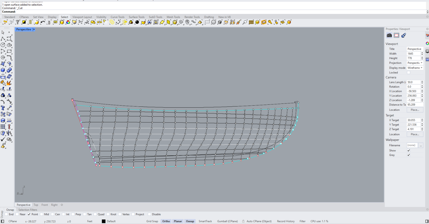
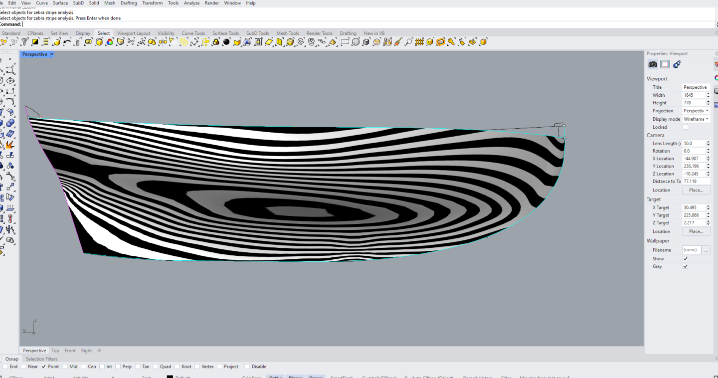
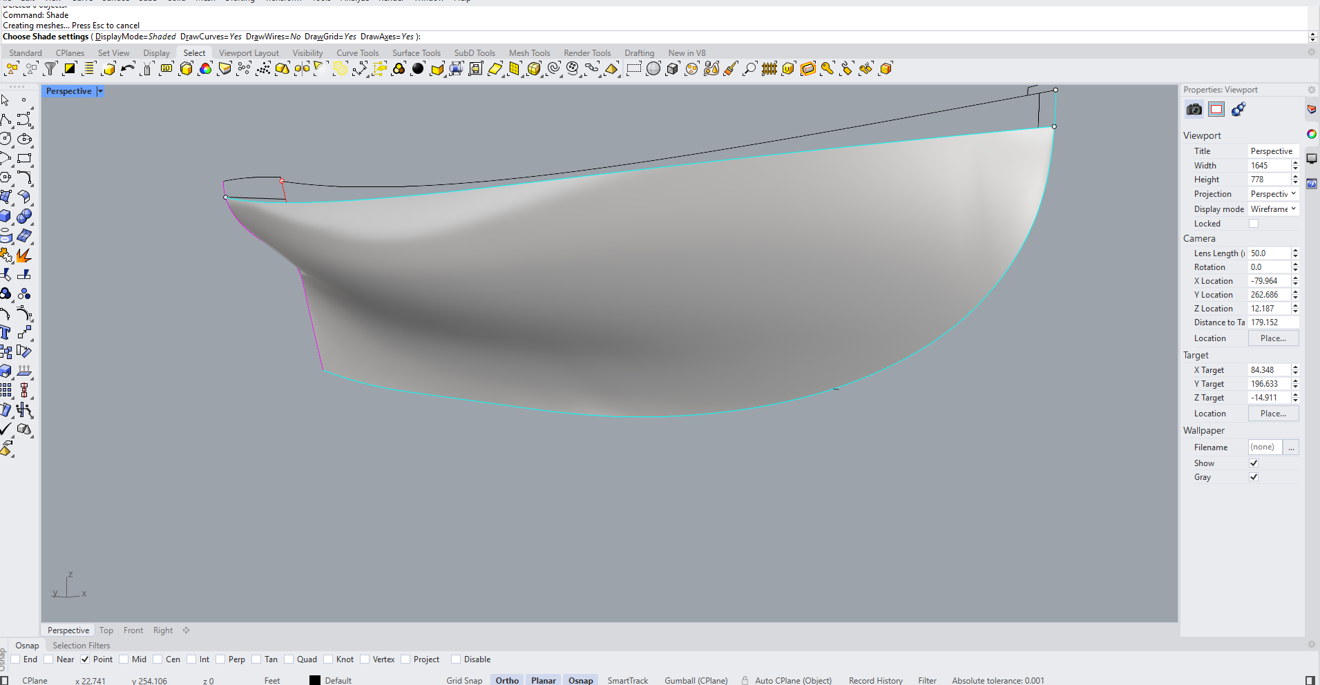
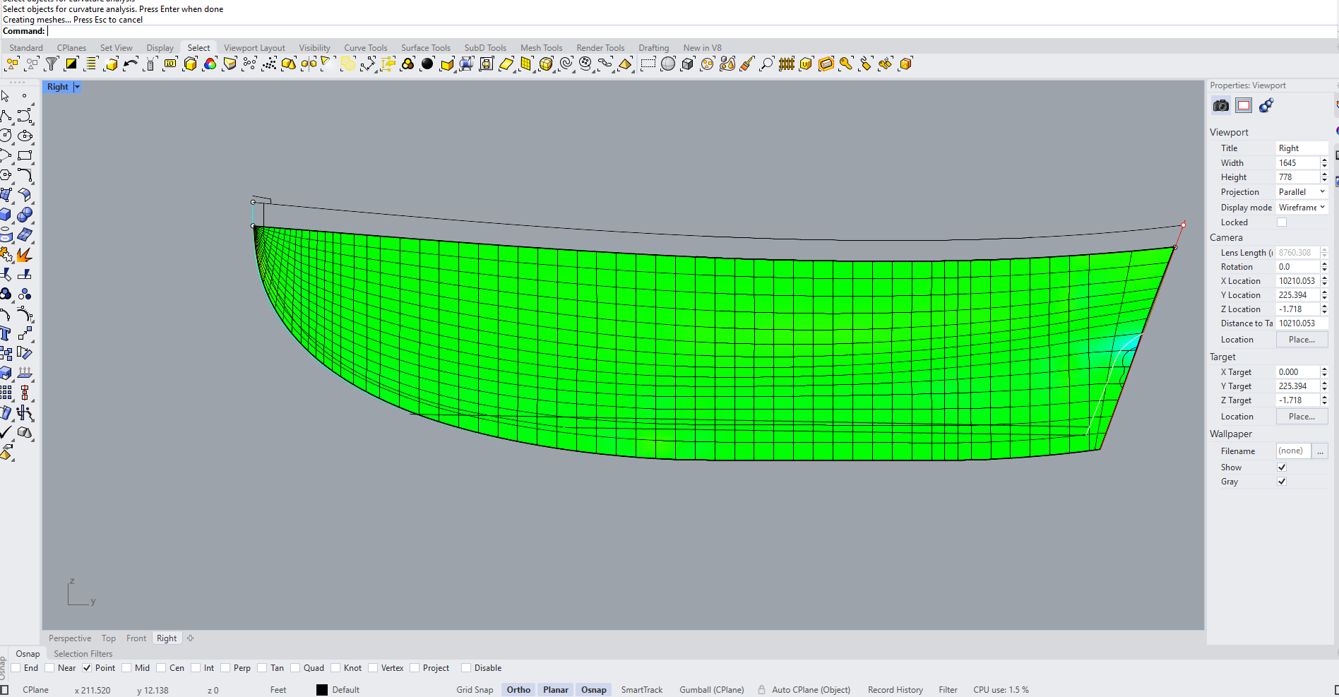
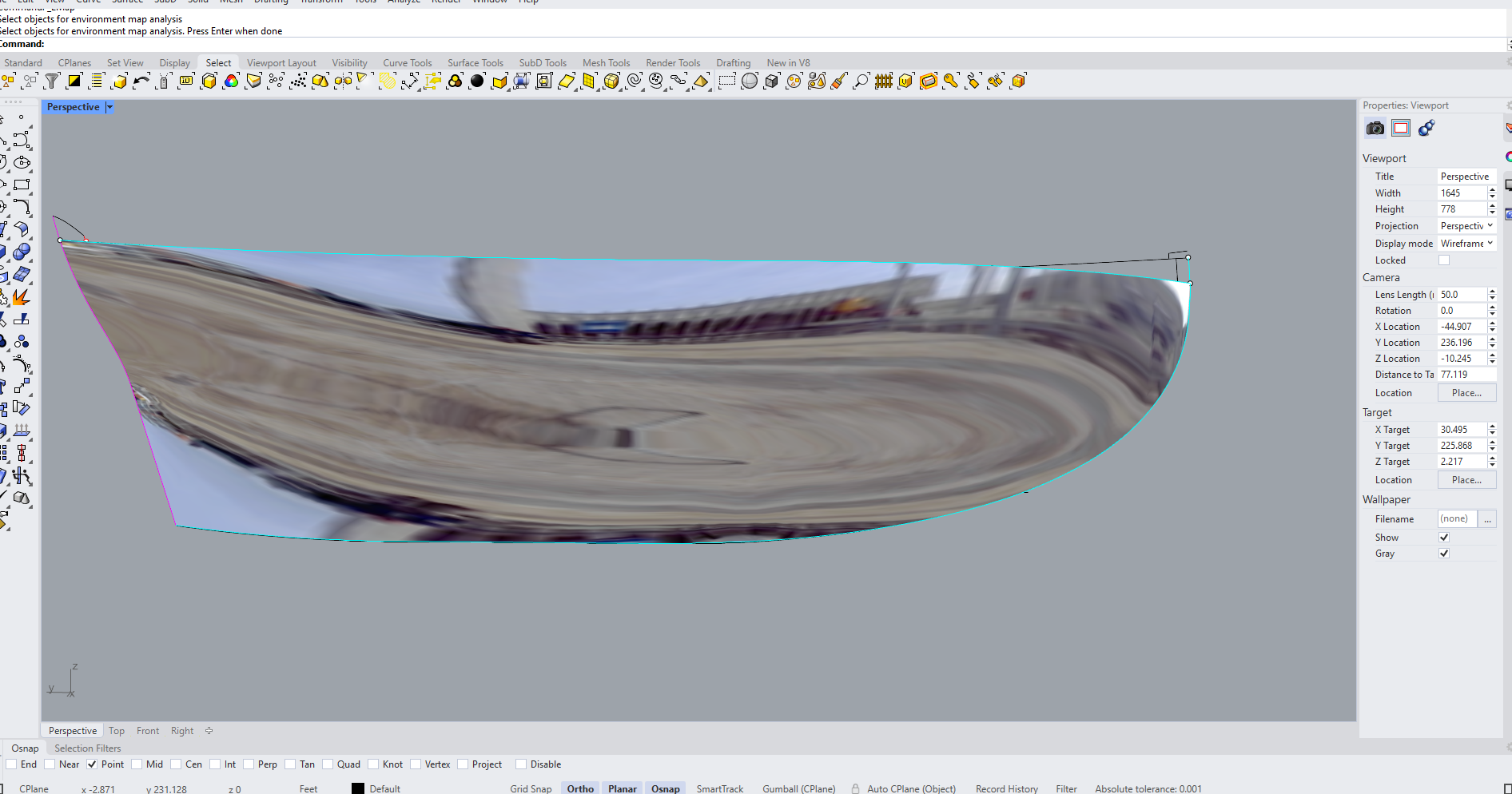
Dear all I think I did it! But first my deepest thank you to all that visited, hit the like button or replied - much appreciated! How right you all are: Now David, I had forgotten all about the diagonals! Silly as my first efforts to loft the boat were actually using the diagonals, which is what Leo did. Thanks! Diagonals coming up bellow. I did exactly this Mark! Still, this led to a stem just short of 9 inches wide, whereas Leo ended up with a 7 inch stem. No matter how much I tried I could not match this without drastically altering the shape of the sheer or having a stem clearly wrong and too far off the plans. Absolutely. After the hull was pretty much shaped, I realised that what appeared as large unfairness in the CAD lines was in reality just a difference of 3-4 mm, and this in the full size boat. I most certainly will Greg and I also plan to visit Tally Ho (if possible) when Leo gets back home. All in good time! Ok, so now let me share the progress made - I must admit I am pretty happy, unless some eagled eyed people find a huge error somewhere! So blending all data sources I found a happy medium for the sheer, the stem, the sternpost, transom, face of stem and keel. I accepted that frame no 2 will be a bit S-shaped (not much). I then went through three lofting cycles. Suddenly, all fell into place! All lines were fair and the frames and waterlines were either touching or just a few mm apart: These are the sets of frames after each cycle - the white frames are the traced ones from Mr Strange's drawings. But is the hull really fair? Enter diagonals! It is actually ok! The unfairness at the stern is because I used the last frame to create the lines - without it the top three diagonals become completely fair. I will actually not be using this last frame so all good. The bottom diagonal is a bit wonky but the distance to fairness in that aft point in reality is just 2 mm in the full scale boat - meaningless. At the bow, again the adjustments to make the diagonals fair are tiny. In any case, I thought I d give it a try. So I faired the diagonals... ......produced the new contact points with the frames and transferred these points over to the finished hull to redraw these frames... ....and then I gave up. It was meaningless, the difference was just a few mm. In the actual boat it would not make a difference, even Leo accepted 1/8 inch tolerance. In 1/12 scale, this tolerance becomes less than 0.5mm. The next photo shows my frames compared the the traced ones - they are pretty close. So lets see the hull! Now, this looks pretty fair. More bellow Adding the rest of rabet at the stern And a couple of photos of the complete hull. I think it is adequate to start the project and the wood will correct any imperfections. This was the first of I am sure many milestones in this very long journey. We are still far from making any wood dust. Take care all Vaddoc
.thumb.png.191d3721e306d6ed0b20a7f2916ff8cf.png)
.thumb.png.099a1930b600fb75341dfaf8519eeab3.png)
.thumb.png.2da31a89a9decd13b3636785b52f75c2.png)
.thumb.png.a1ed705a563a2e97fde8eaff41e7e735.png)
.thumb.png.41d161f27e8cc5e8a3312b8c27e7d45f.png)
.thumb.png.d73180d26d44dcad881ca039026cd6ca.png)
.thumb.png.ebbd4cfb026023ccc2de7296aaf52296.png)
.thumb.png.03fa44cb7c3197e660ca2080d62ed271.png)
.thumb.png.857adc3d74163a0b57238a00c7e01bc5.png)
.thumb.png.a273e709ff48b45fad7d4b36b775e749.png)
.thumb.png.35675a002e84e3ec732ae27d778cd60a.png)
.thumb.png.e93b8ff5a4d786450ec03a516a4148a9.png)
.thumb.png.bba1537c9eb4f08a90d53c8e3aafd8cc.png)
.thumb.png.5e6c68f7399370d7ce117efe1738d49b.png)
.thumb.png.be24869471c9009c72c316960ce171ae.png)
-
This is such a fun project to follow Phil! Quick question, why do you sand the superstructure between paint coats? Vaddoc
- 482 replies
-
- 3
-

-
- minesweeper
- Cape
- (and 1 more)
-
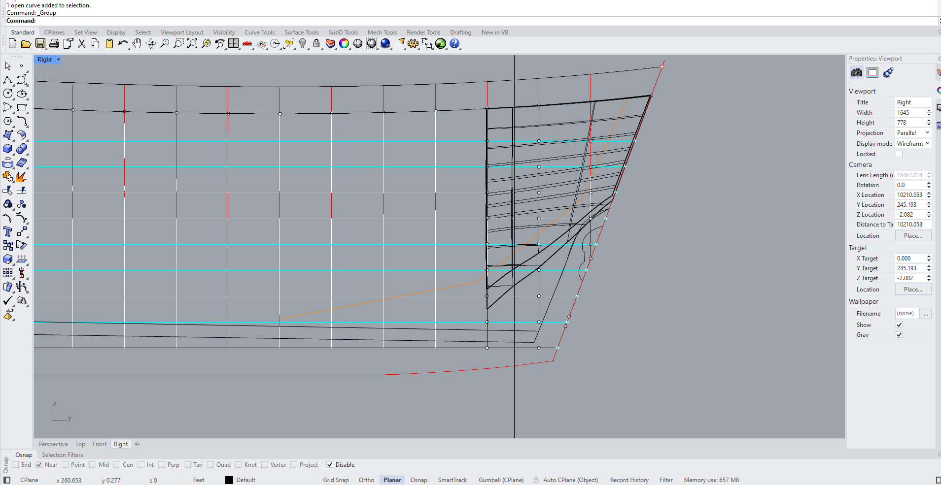
Dear all I was too fast congratulating myself! Not only I have no progress to show in this short update but actually I ve gone backwards. Still, my understanding of this hull has grown. Now, this is going again to be a bit technical which means quite boring! When I went to do the second round of fairing, I noticed that the frame No2 had acquired an S shape. I am sensitive to No 2 frames - consistently in my boats they creates issues. Looking deeper, I did not like it. So I scrapped everything and started again, this time using the table of offsets. But I again run into problems as things did not add up. These are the issues I have encountered so far with these plans: 1. The sheer is difficult to define The start and finish of the sheer, which are at the face of the stem and at the back face of the transom, are not given in the table of offsets. These can be measured from the lines drawing but it does not work very well. Furthermore, the sheer in the lines drawing is far from fair and the half breadths and depths in the table of offsets also do not produce a fair sheer and do not work at all well with all the other information given in the various sheets of the plans. It took a lot of head scratching but finally, combining all sources, I managed to produce a sheer that I feel is half descend. 2. The shape and position of the stem is difficult to define. This information is given in three places. In the table of offsets, in a separate sheet in the plans where distances are give from the baseline and the forward end of the sheer (the latter is NOT given though in the table of offsets!), and also can be defined by the plan drawings. These three sources provide three different stems! The difference is not huge but still significant. Again, by blending everything I think I have a reasonable stem 4. The width of the face of the stem after tapering from the rabet is a bit of a quizz Now, this face progressively widens from the top of the stem finally reaching the full width of the keel. These widths are given at various heights but still fairing of the lateral edge of the face is needed so that this transition is smooth. I finally managed to do this, which of course changed some of the dimensions given in the table of offsets, but, whereas Leo starts this face at 1.25" wide, in the lines drawings it is much wider, almost 2" or more. (This information is not written anywhere else). In 1:12 scale this face will be 2.5 mm so maybe a bit too narrow. In my CAD drawings I ve followed Leo and did it 1.25" but may need to revisit this to make it wider - this will unfortunately mean that I will need to redo the sheer. We will see. 5. The sternpost and transom dimensions are not given I traced the lines drawings to get this. The width of the sternpost is not given either but luckily Leo mentions it is 4" wide - which looks about right. 6. There seems to be a problem with the body plan Now, this is important. The plans contain a table of offsets and also the lines in profile view and body view. Now, these do match, with the exception of the bottom end of the frames. (All of the frames) In the following photo, the waterline is the blue line. Note what is happening with frames 1 and 2. The top ends of the frames indeed meet the sheer where they should in the profile plan. The green lines show where the frames should finish according to the table of offsets. These heights are correct in the profile plan but not in the body plan. The frames seem to reach the keel quite a bit higher. This is the case for all frames. (Apologies, for frame No4 both lines are green but the upper one should be red) I really tried to figure this out but cannot find an explanation. Interestingly, Leo in his own lofting seem to have positioned the bottom end of frame No 2 in the position given in the table of offsets - about 3/4 of the way down between the 2 waterlines Frame No 2 in his plans appear to be ever so slightly S shaped - which is what I think it should be. Now, I ve been fighting this a few weeks now and am a bit broken, I need to recover a bit before I continue. If any of the wise elders can provide any advice on the discrepancy between the body and profile plans, I really would be grateful! Take care all Vaddoc
.thumb.png.e980ebaec8e723a80c488ce883572582.png)
.thumb.png.7310f79bb6f9d664c4d2764d6cf1c85e.png)
.thumb.png.b0d85a1234e324f35ba5e8c652b47883.png)
edited.png.6f8b13919616cdad61a0a38ef98bf755.png)
.thumb.png.f543d8b2eb7bb39df87235a43371d0bb.png)
.thumb.png.e478dbb978344554559af31fdaaf0c36.png)
-
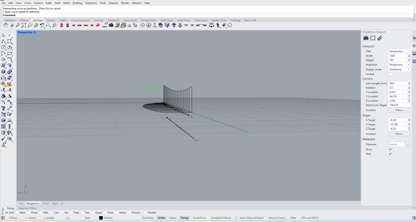
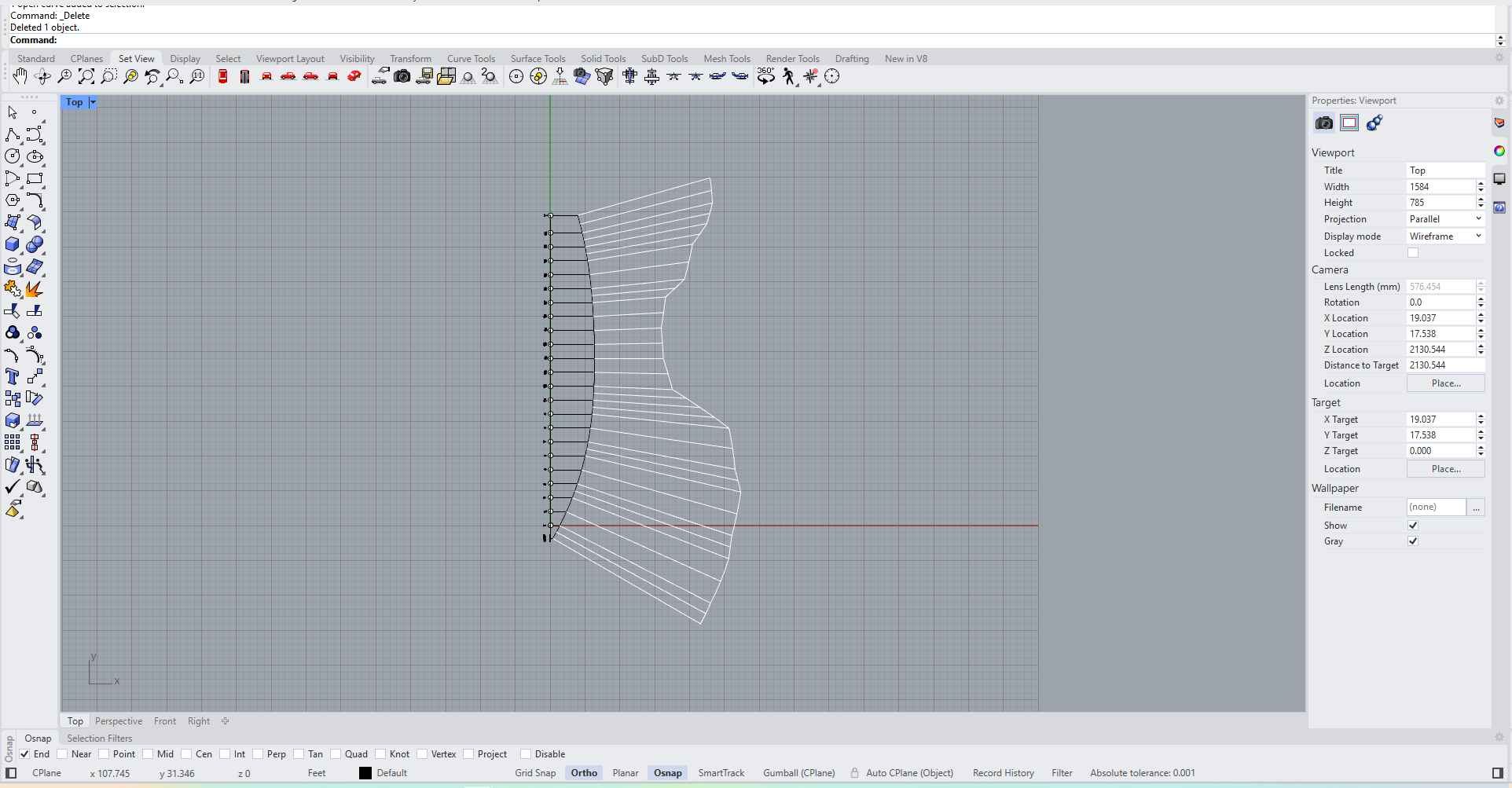
Dear all A wee bit of an update as I found a bit of time here and there to work on the boat. No sawdust yet (and will not be for a long time!) but a lot of digital ink spilled over my monitors. @KennyH78 Kenny, if you decide to build Tally Ho, let me know and I will send you the CAD file - if I manage to loft the boat that is. Still, lofting the boat is fun but also would give you a much better understanding of the hull lines and how she should be built. So lets discuss Tally Ho's plans. There is no doubt that there are issues with the plans in the archives of the Albert Strange Association. Tally Ho is a bit different to all the other boats I have lofted. The curvature of the hull does not stop at the rabet but continues at the stem, sternpost and all the way to the bottom of the keel. I think I remember Leo in one of his videos mentioning that there were missing data from the plans, specifically the offsets for the stem and sternpost. This is indeed one of the issues I am facing. Furthermore, the paper has been distorted over the years, there seems to be a bit of damage but also, my copy of the plans has not been scanned very well so there are some gaps with the lines and the text. Also, CAD is very unforgiving and I am picking up all sorts of issues with the plans - Leo must have seen this but to a lesser degree, as he did not use CAD for his lofting. Ok, so lets get a bit more technical - This may be boring but may also help some people with their lofting (and lofting of Tally Ho in particular). For me, the first step in lofting a boat is to find the edges of the hull surface. These are the sheer at the top, the rabet/bottom of keel at the bottom, the sternpost/transom aft and the stem with its rabet at the front. Most but not all of this info is in the table of offsets but again there are issues. The table of offsets does not seem to correspond to the dimensions as measured using the plan lines. I initially created the sheer using the numbers from the table, however the position of the stem and transom, which define the start and finish of the sheer, must be taken from the lines - also the width of the stem. Combining all these does not really work. Using just the lines again does not work - the boat comes out short by half foot and generally things do not work well, the lines are not fair and there are issues with the keel. So I decided to ignore the table of offsets - I only used the half breadths for the bottom of the keel. I traced all the frames (except frame 13 which is missing) and positioned them in their stations (2 feet apart) using the same reference point to make sure they were aligned. I added some diagonals of my own - Leo was right, this boat is much easier to loft using diagonals. I then added the sheer, keel, sternpost/Transom and stem. Again it did not work! So I went back to watching the You Tube videos and the solution was there. You see, Leo had the same plans as I do but he also had the boat! He mentions that the sternpost face is 4 inches wide - excellent. But he also showed this drawing: This shows that the stem is 7 inches wide (although he chose 8 inches to give more support the the hood ends of the planks. The lines show the stem less thick at 6 inches. Mine was 10.6 inches so clearly wrong. The face of the stem is only 1.25 inches and the rabet 6.75" from the stem face. This was very useful. I also measured the distances of the stem from station 6 at all waterlines, to get its shape I used all these to draw a new stem with a new shape at a new position. I then created a new sheer from the top of the frames I had traced. Combining all worked beautifully! The boat is now 47.5' long and the stem just over 7" wide! The drawing bellow is the same as Leos. The yellow line is the contact surface of the planks with the stem. The arrow shows the half thickness of the stem. The blue line is the sheer. So now with all boundaries defined, it was time to start lofting. Some work was done to get the half breadths at the bottom of the keel correct. I traced all the diagonals, waterlines and buttocks. They were of course all over the place: Fairing this line produces a much more satisfying curve. After all the lines had been drawn and faired, new frames were produced - using only the diagonals. All new frames drawn and faired. I noticed that there was very little deviation from the original contact points with the diagonals. The last frame aft is a different colour because it did not really cooperate. This needs more work. This is just the first cycle of lofting but I tried to make a surface and I was half surprised how well it worked. I knew the lines where not that far off but I did not expect this: The hull is already reasonable and the areas where usually I have issues, at the bow and stern, look mostly ok. The boat needs at least one more lofting cycle but it looks promising. Take care all Vaddoc
.thumb.png.126476912b174625206065da87d28daa.png)
.thumb.png.acd331e94c74569f4b883ee4949a01af.png)
.thumb.png.5adf6aa70ee5fb8bc3fd9697945d277a.png)
.thumb.png.8d05a3388ecf45bcff41116c2ea6c57c.png)
.thumb.png.0d78702f15094d9a0951695ddaf68c8e.png)
.thumb.png.a1eea1c8e16a08e46d4b5bd07e5dc1b5.png)
.thumb.png.58eb9a66692dd165c4ecefb433b4a989.png)
.thumb.png.36b8e2e9f9ad294a4405be0ea9092578.png)
.thumb.png.8751bbed11527fb10aaaa60c5f9be6ae.png)
.thumb.png.0cf6d321959cbc7ce1f9268cb79ad811.png)
.thumb.png.4190a0a14290d32623f3428390df207b.png)
-
Perhaps this will be helpful, there is a build log where styrene rod was used, then a heat gun to melt the part of rods sticking out into round rivet heads that could be painted. Vaddoc
-
@Desertanimal @Knocklouder Chris and Bob many thanks, and to all that hit the like button, great to have you along! @Keith Black Keith, I was actually thinking the same, life certainly has the annoying habit of getting in the way. This boat in some ways is like the Deben I ve built in the past, but larger and far more complex and Lord knows how much work that boat took, when I had much more time. But we can't leave MSW without a model of Tally Ho so let's hope everything will work out in the end. @wrkempson Wayne wow! This is just great, thank you for sharing. It is interesting that you reached the same conclusion, that Tally Ho's plans are like a puzzle with a few pieces missing. I will need to study your master lines and all the good work you did, see how it compares to the plans and the table of offsets. Which software did you use? Best wishes to all Vaddoc
-
Ok, so lets do a quick follow up post with the first thoughts on this. To start with, the plans do not seem to be as comprehensive. There are the lines and some drafts of the keel and a table of offsets but something feels not quite right. Then again, Leo managed to loft the boat so everything should be there. I checked the plans and the lines are not really straight, or vertical. This is common however, paper distorts over time and CAD is really very unforgiving to plans drafted 115 years ago. These lines will be ok to start but serious lofting will be needed. Still, this seems a much easier boat to loft than Hercules I imported the plans to Rhino and scaled them to the actual boat size. I need to dive more into these but it seems that the distances as measured from the lines plan are not the same as in the table of offsets. I am not sure where the stem/start of sheer should be or where the Transom sits. To make things worse, the plans I received do not seem to have been scanned very well. Most of the text in the table of offsets was missing but I managed to recreate it by watching Leo's videos - he had the same plans and they can be seen in a video, so I was able to read almost all of the missing text. A part of the lines plan has not been scanned well and another small area at the bow is missing - apparently permanently damaged as it is missing from Leo's plans as well However, the same lines are easily found on the internet, clearly copied before the damage occurs so I scaled this to size and used it to fill the gaps - kind off. So I blended all together and came up with a sheer plan view Then added the profile view and created the sheer from these Adding the other half, shows a bit of the boat shape Now this is just a study of the plans as I am not really sure where the sheer begins and ends, but it's a start. Until next time Vaddoc


-
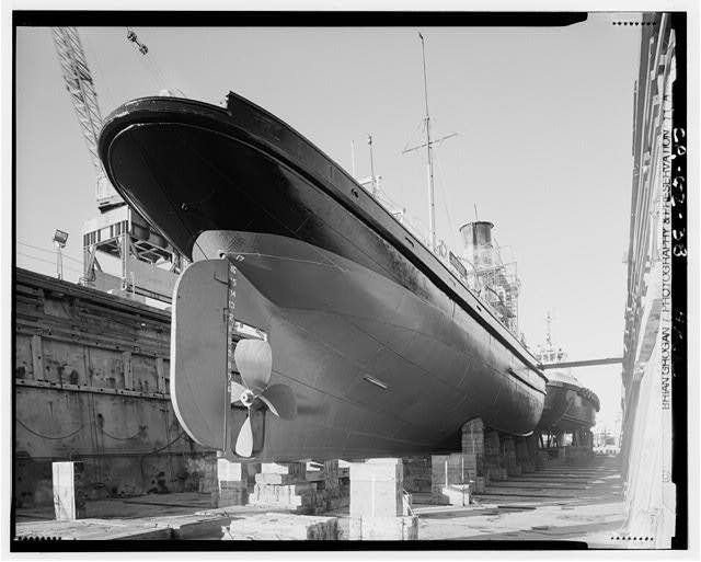
"It's amazing what a boat can do" TALLY HO with fidded topmast and spinnaker flying. Photo; Beken of Cowes, 1927. Tally Ho is not just a boat - it is an amazing story of friendship, perseverance, skill and success, a crossroad of many journeys - of men and boats. It all started with Albert Strange, a man of many talents, with a passion for sailing and for designing light cruising vessels. He designed Tally Ho (originally named Betty) which was built and commissioned in 1910. The Albert Strange Association website is really the best place to learn about this remarkable person. https://albertstrange.org/biography/ Tally Ho lived a colourful but hard life. The highlight is, or rather had been up to now, winning the Fastnet race in 1927 but then, in 1968, she actually sunk hitting a reef in Manuae, near Cook Islands. She was then raised and repaired. https://sampsonboat.co.uk/about/tally-ho-history Many people came and went and Tally Ho was brought into disrepair, hauled ashore somewhere in the west cost of America and placed under a huge tarpaulin. She was put up for an unlikely sale, destined to be broken up. There comes Leo, a fearless young man with a dream - he bought Tally Ho for $1 and then spent 7 years rebuilding her from the ground up. The journey can be found on You Tube, Leo has posted hundreds of videos and through this funded the project. It is a fascinating journey with its ups and downs, happy and sad moments, triumphs and disasters. She is now all finished, truly a wonderful boat, slowly making her way back to the UK. Watching the videos (I actually picked all this up rather late) there was no doubt in my mind that one day I would build Tally Ho. This will be a big project and at this time (and for the foreseeable future) I have no time to spare, limited finances, multiple other endeavours and Hercules half way through. What better time to start building Tally Ho than now! After all, her story is one of overcoming obstacles, with a launching date 2 years from now - so all good. I hope I will be able to pull this off and also, to do the boat justice! I contacted the Albert Strange Association and got the plans. I ve been sitting on these for months now but I finally fired up the computer and started drawing lines with virtual ink on CAD. I have not decided on the scale yet but it will be large. Take care all Vaddoc

-
Great job on the hull Phil! I usually seal the wood and spray a thin film of modelling primer on hulls before painting. I am very close to painting my hull as well. Are you planning to do anything to the raised edges left by the tape? People apparently sand these but I am not sure how this could be done without ruining the whole paint job. Vaddoc
- 482 replies
-
- 3
-
-
- minesweeper
- Cape
- (and 1 more)
-
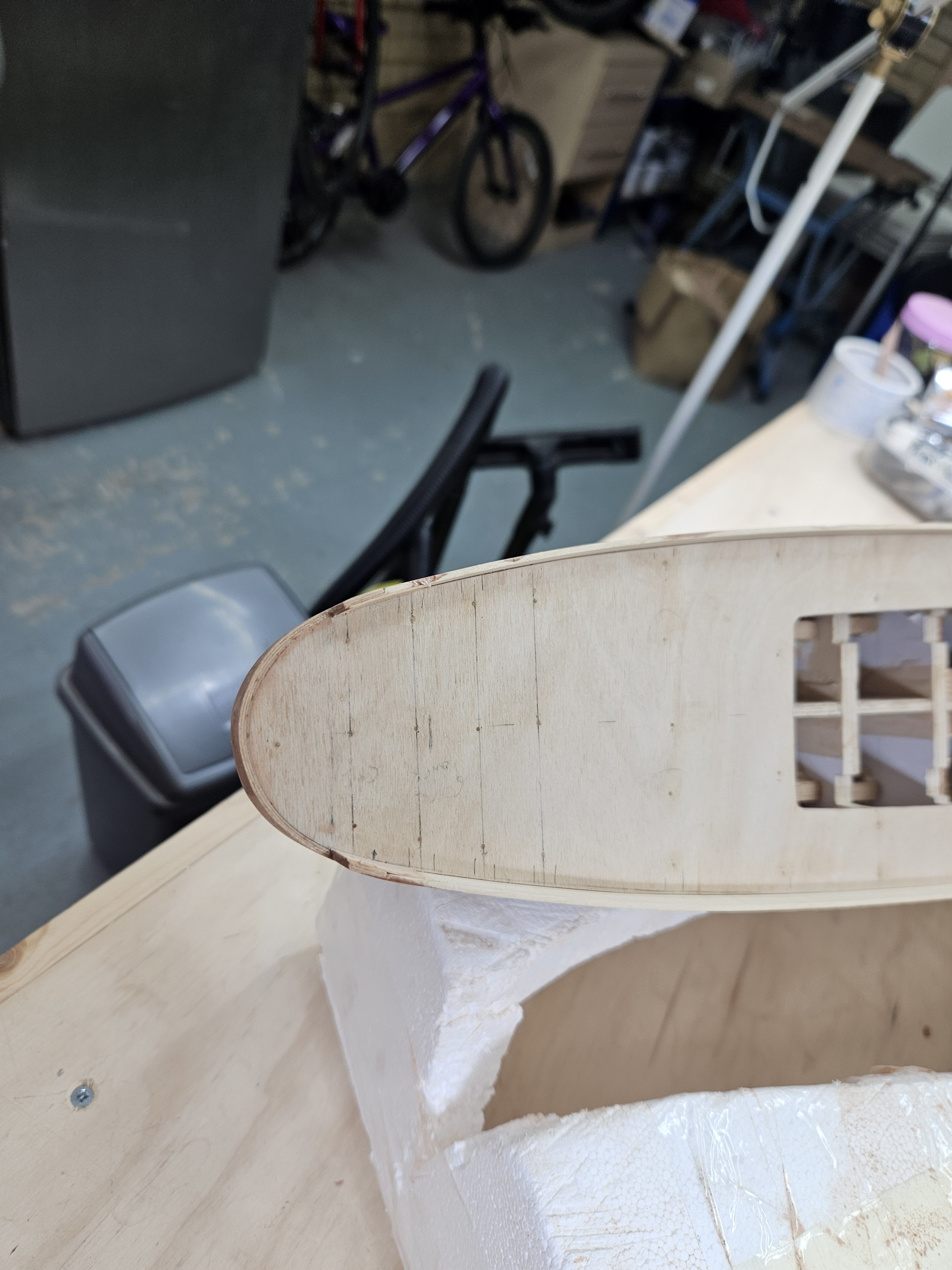
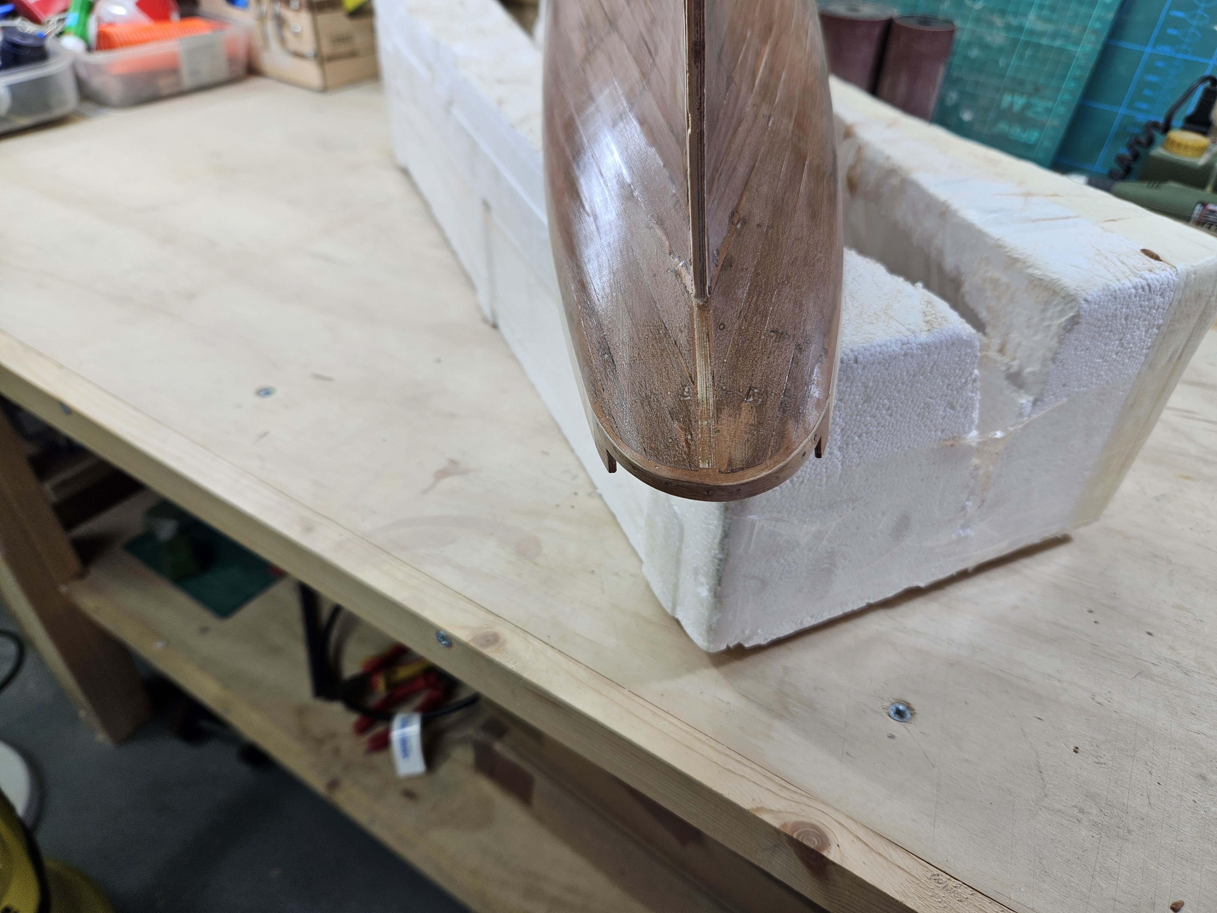
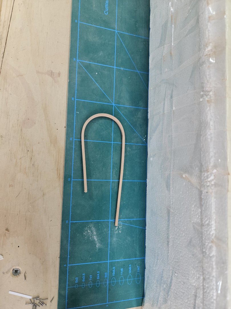
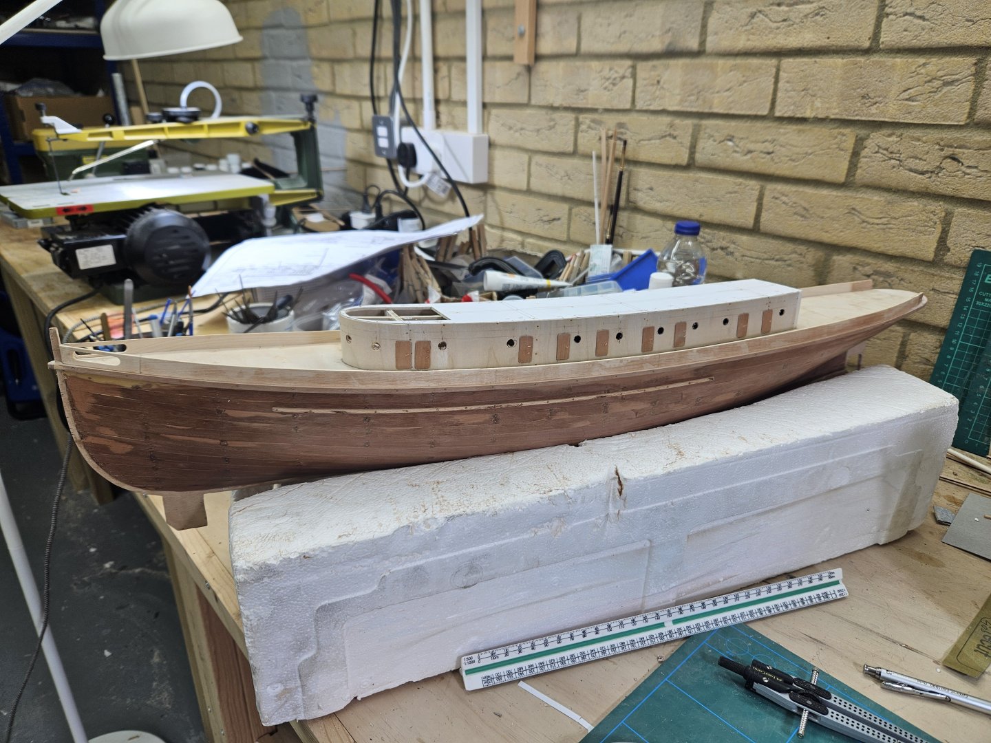
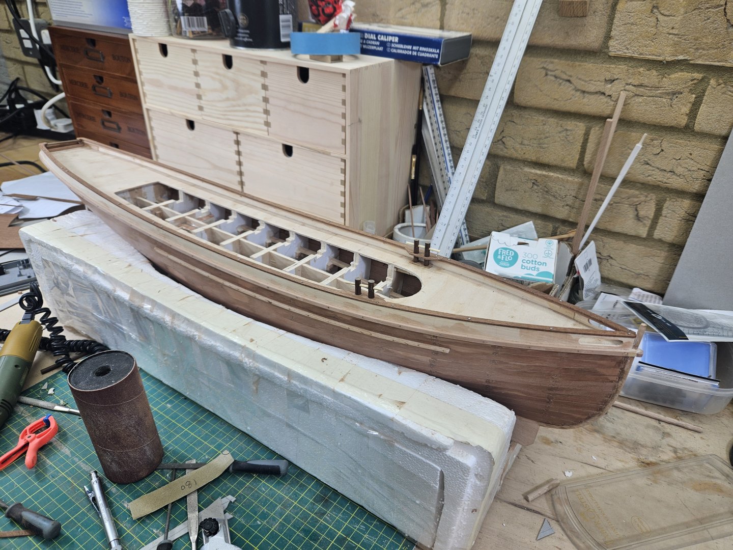
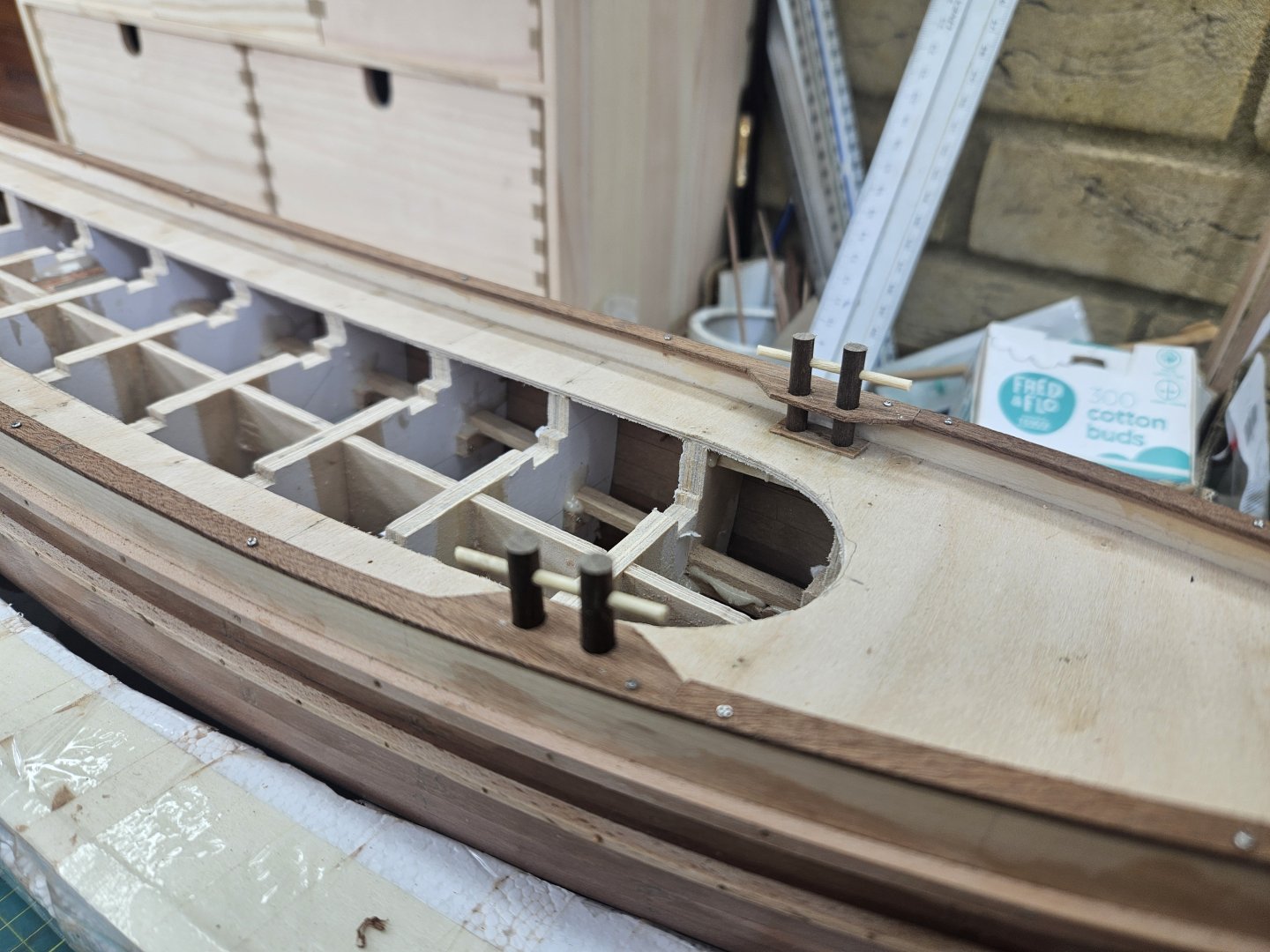
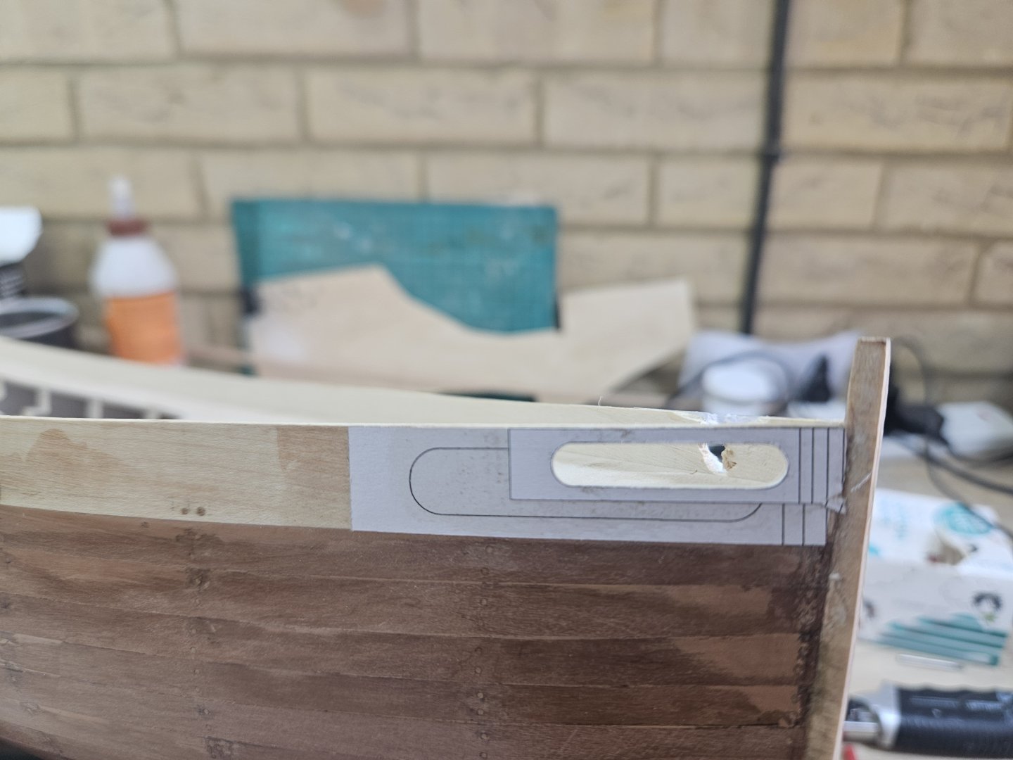
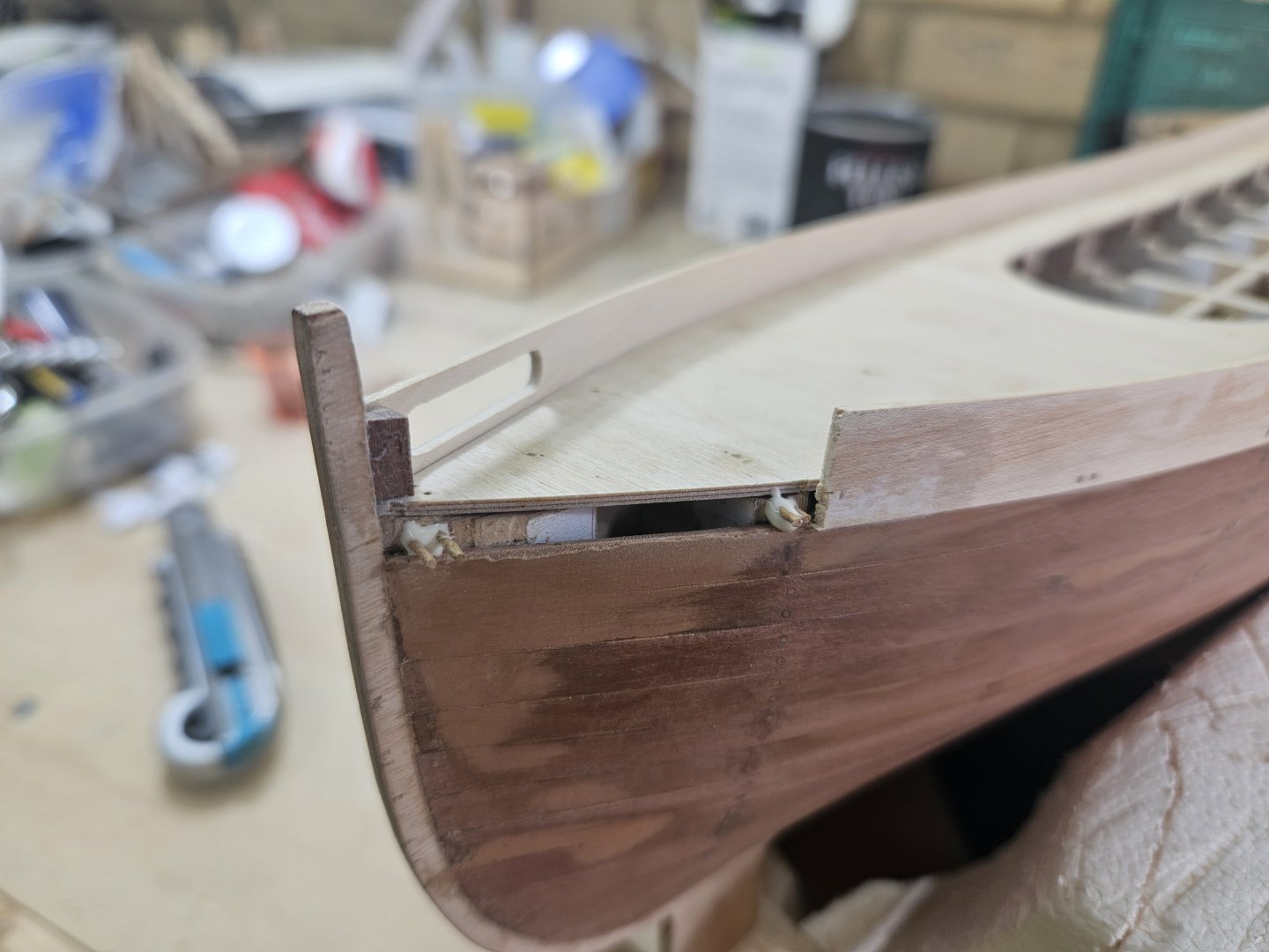
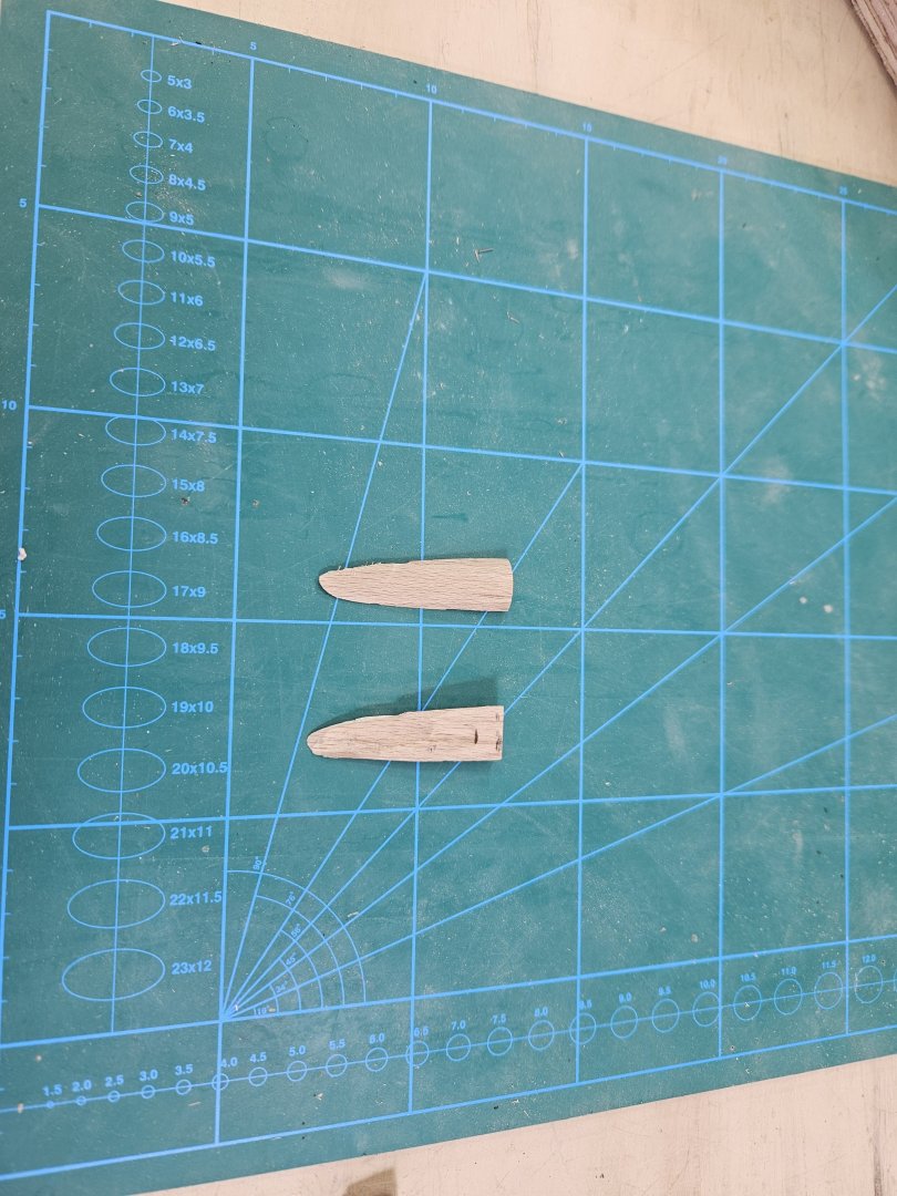
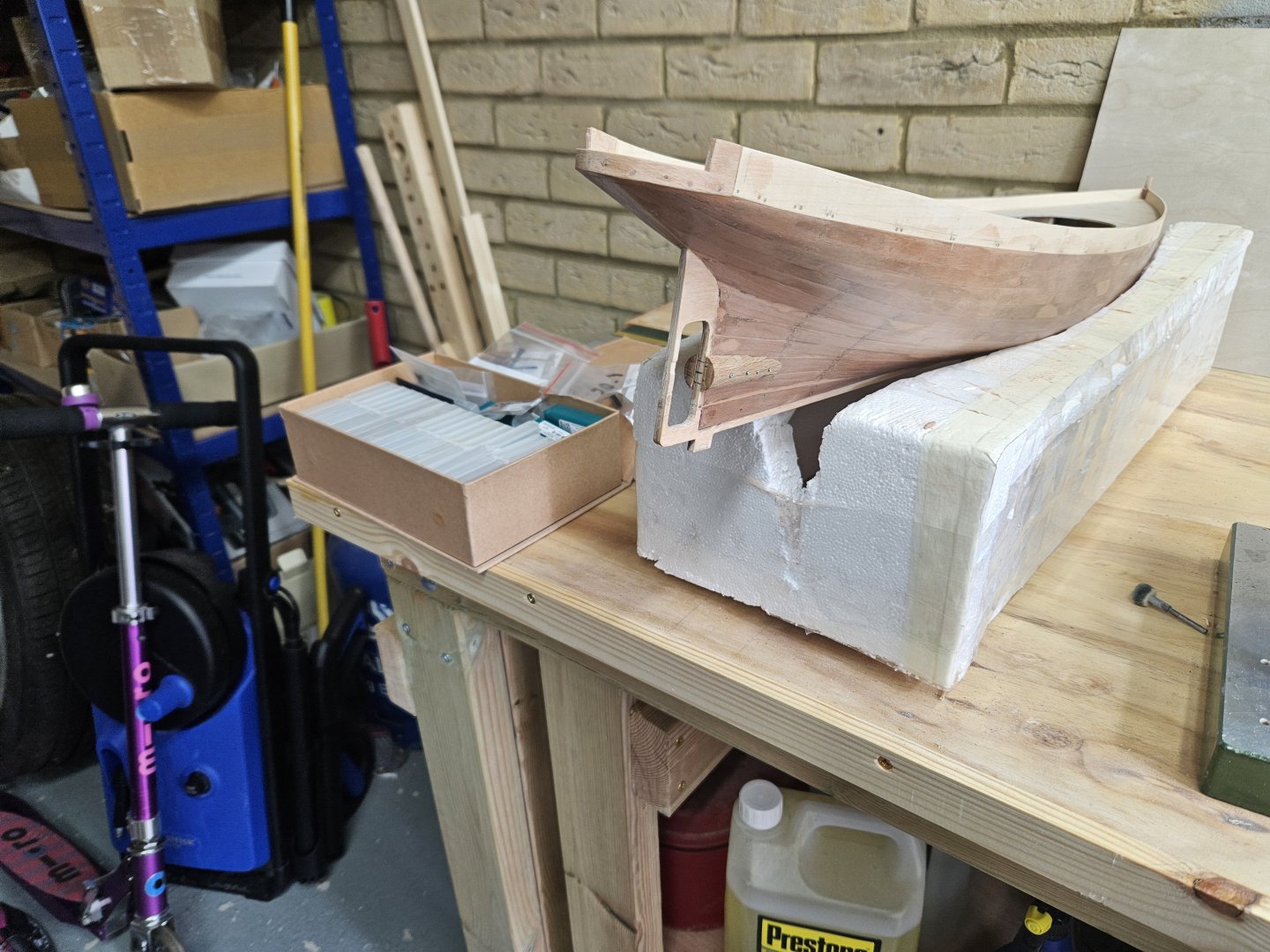
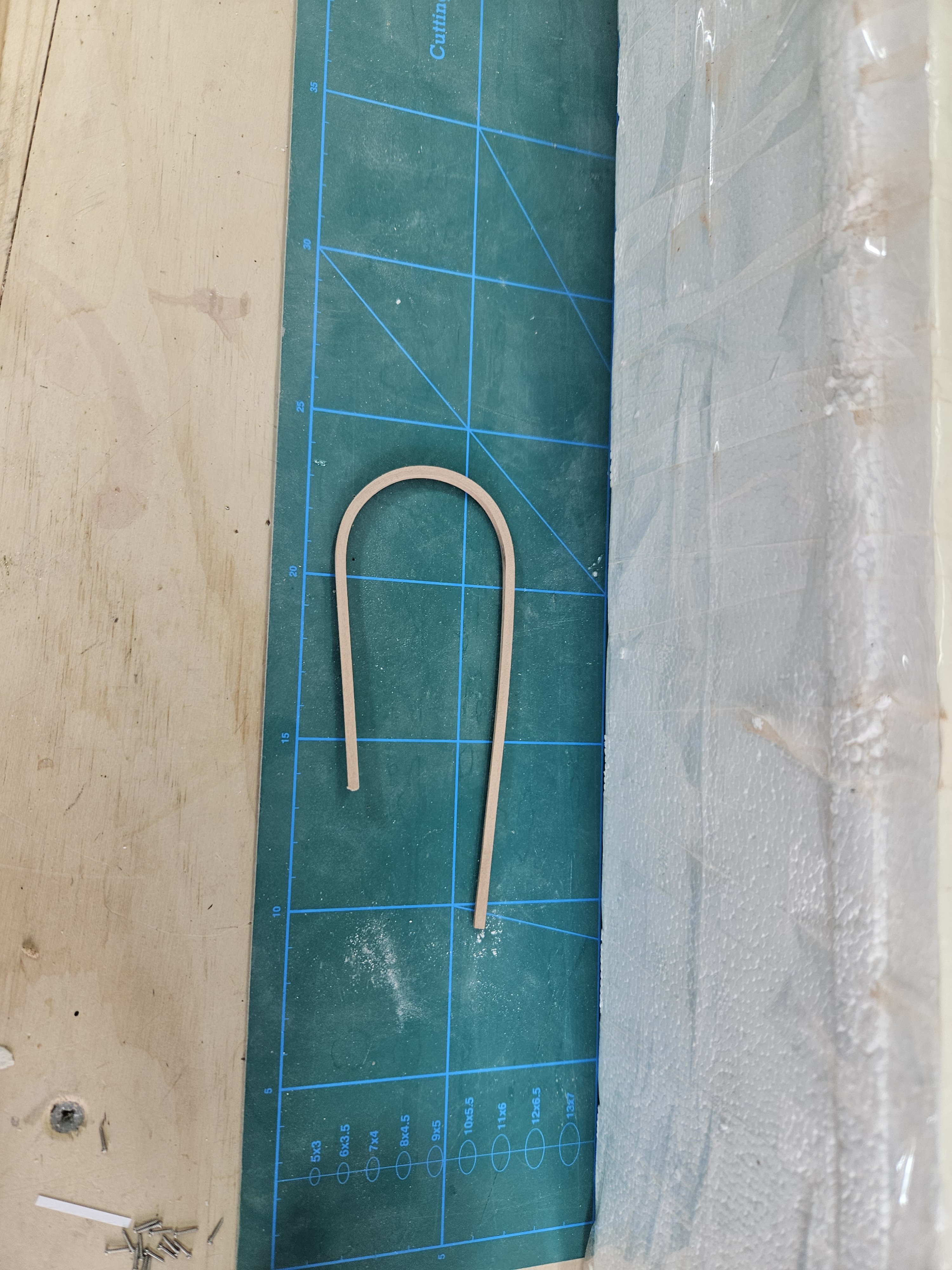
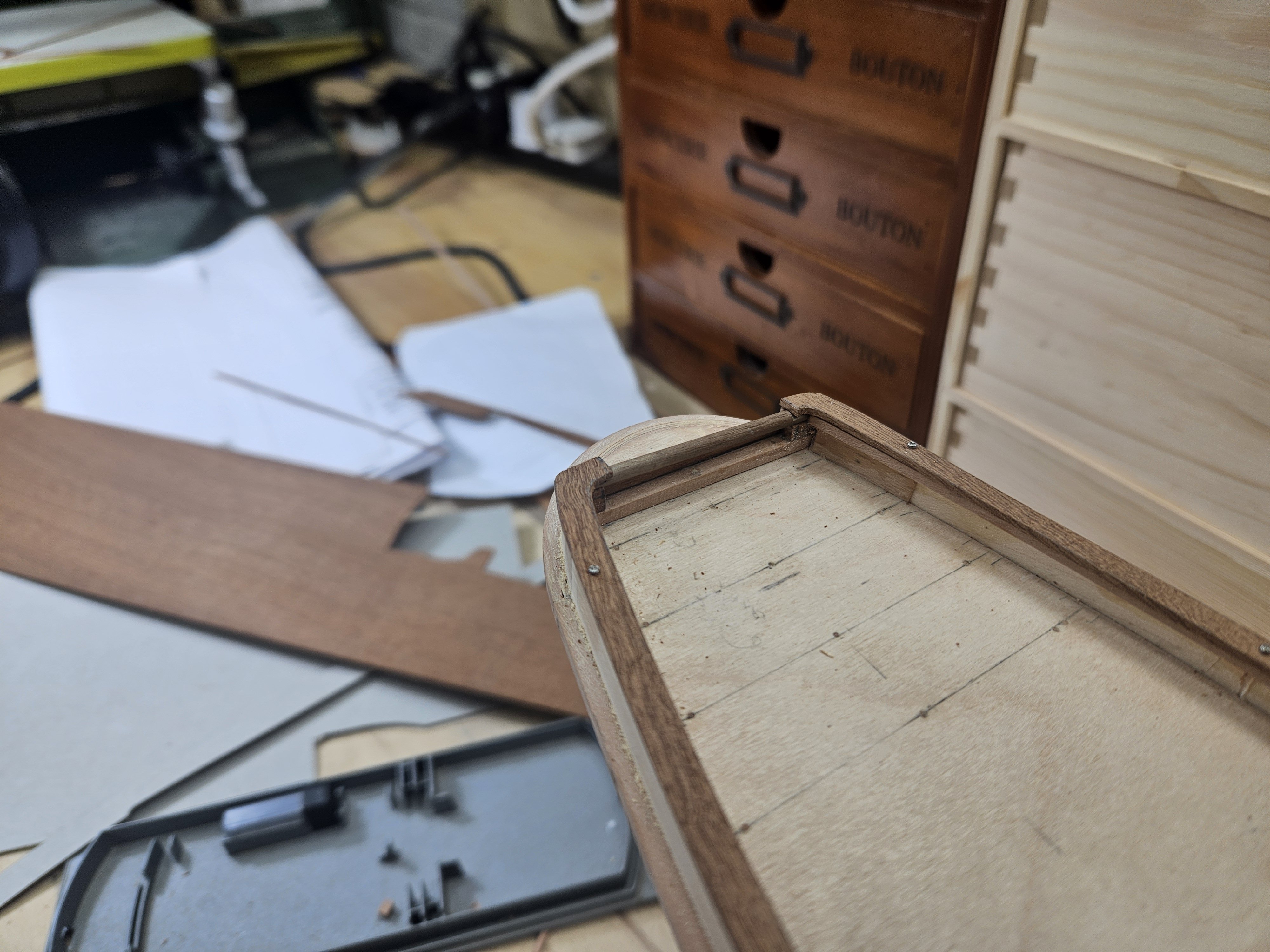
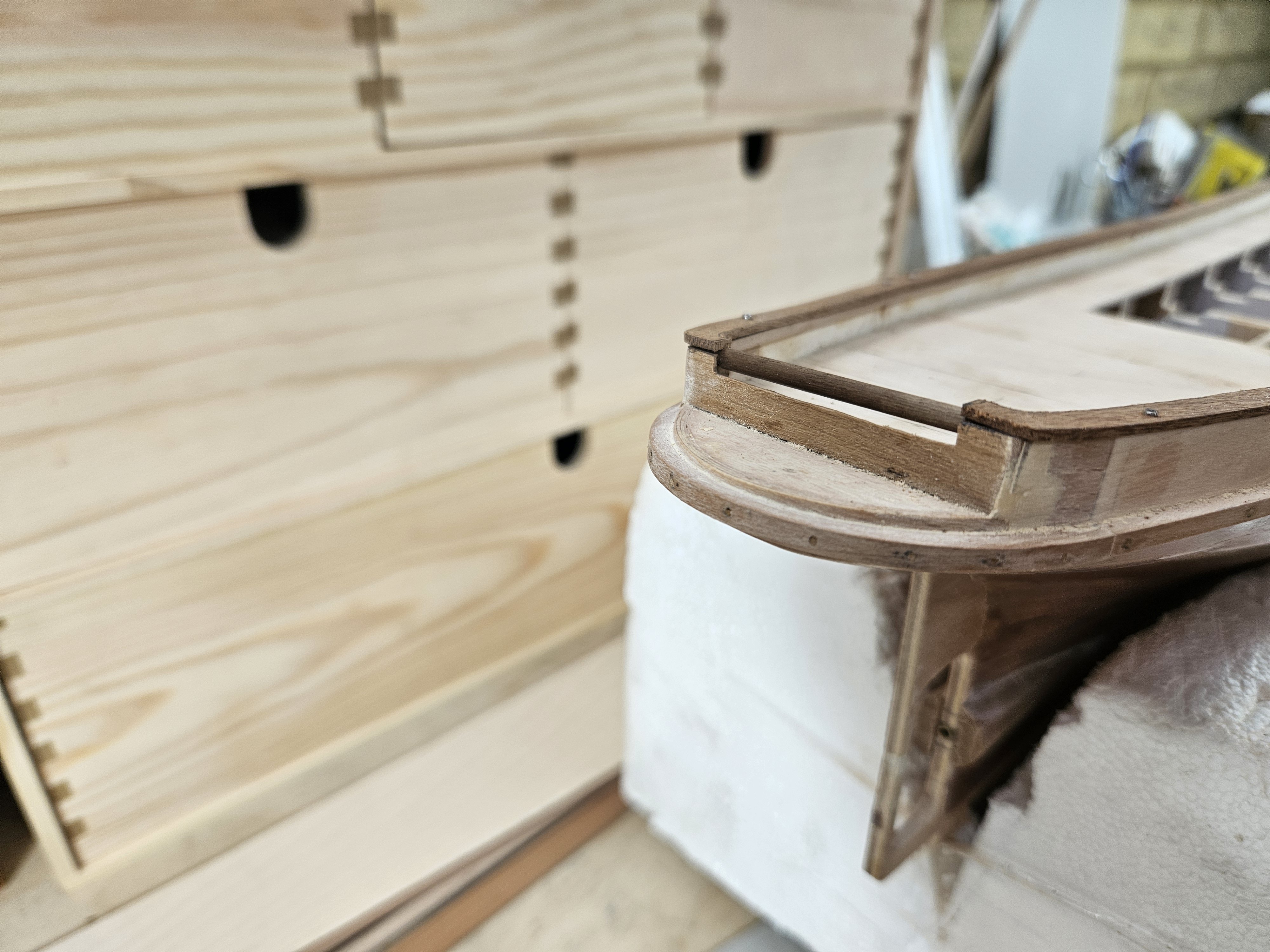
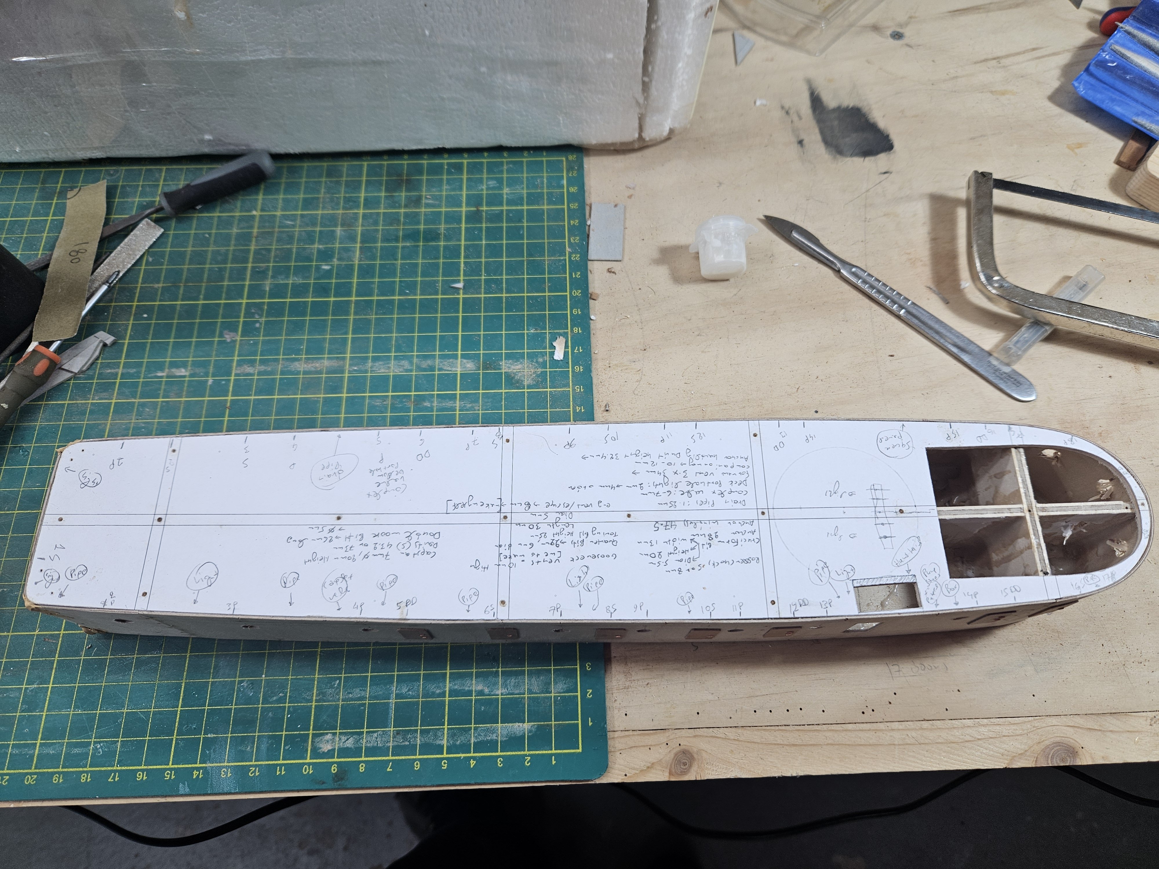
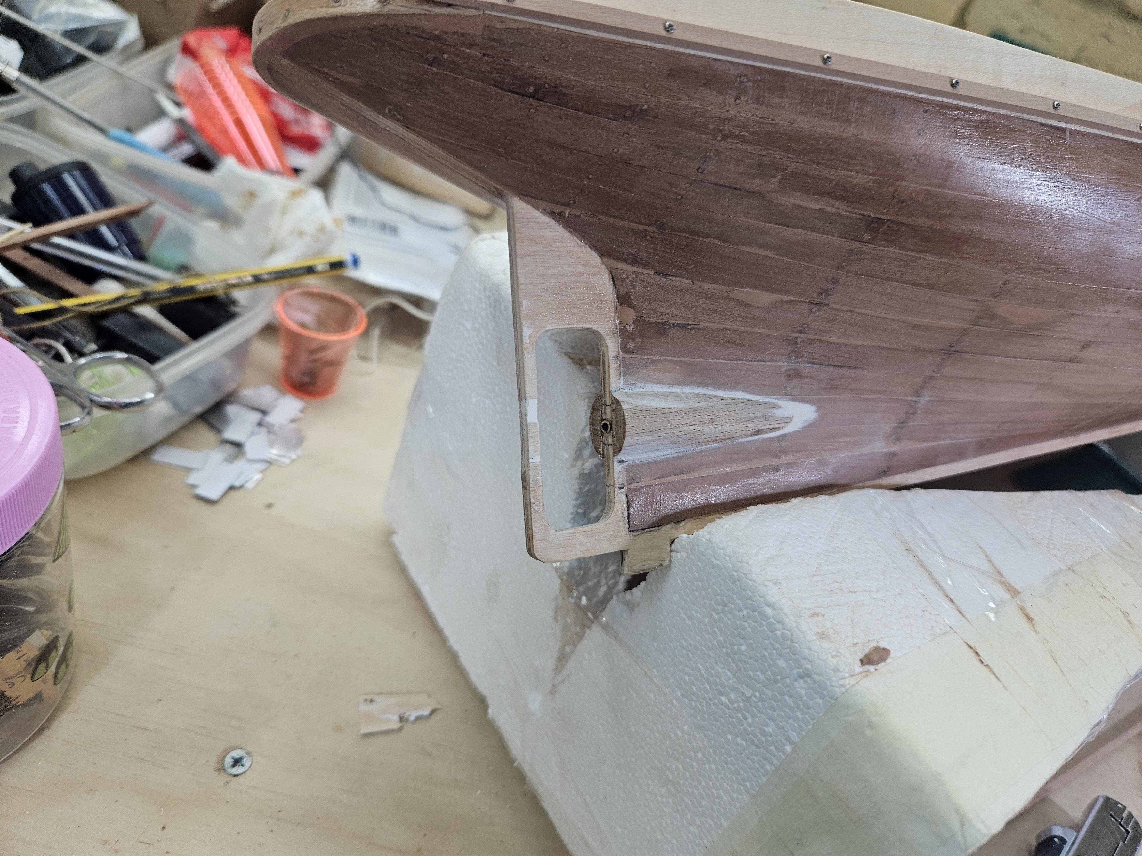
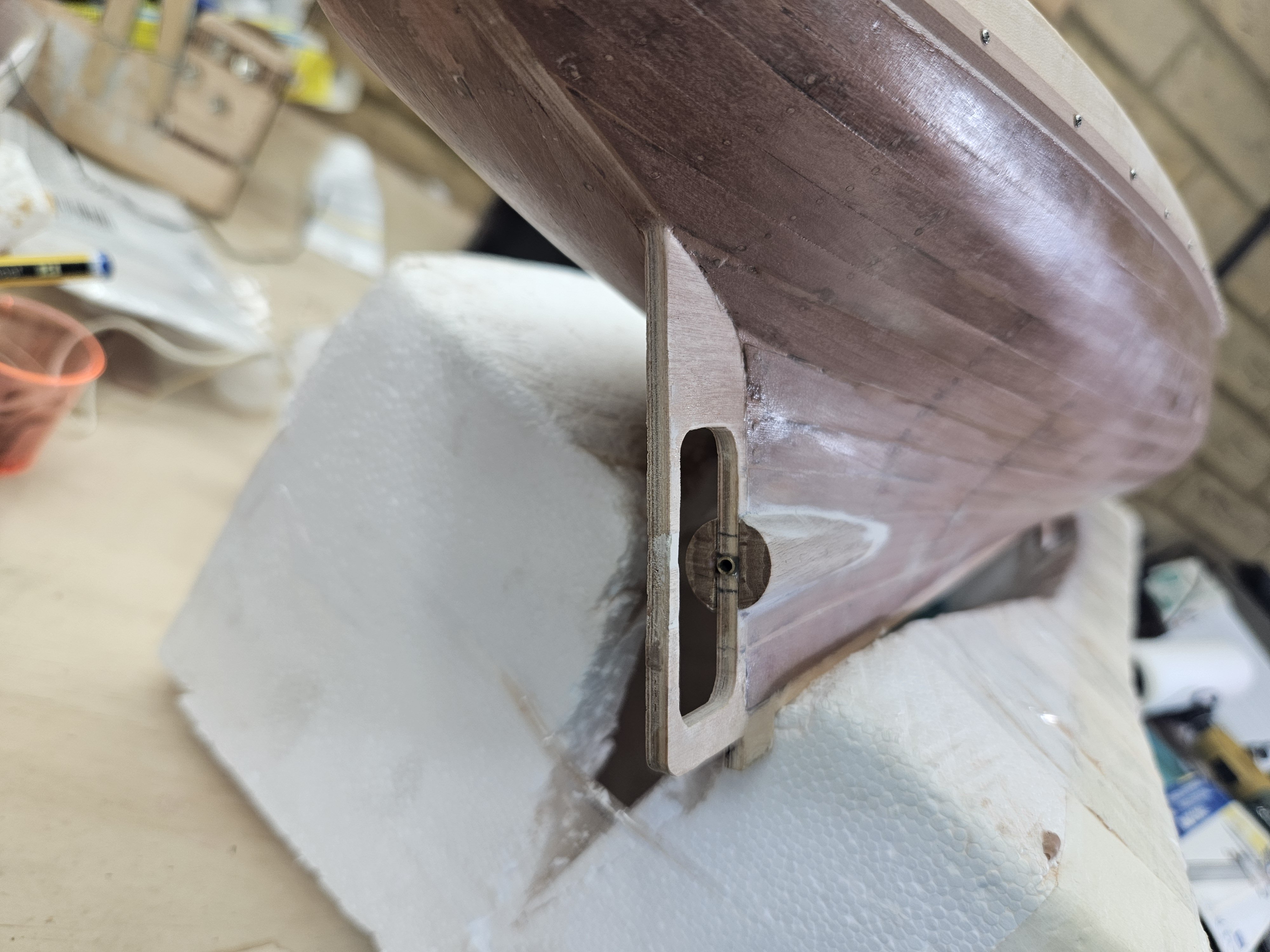
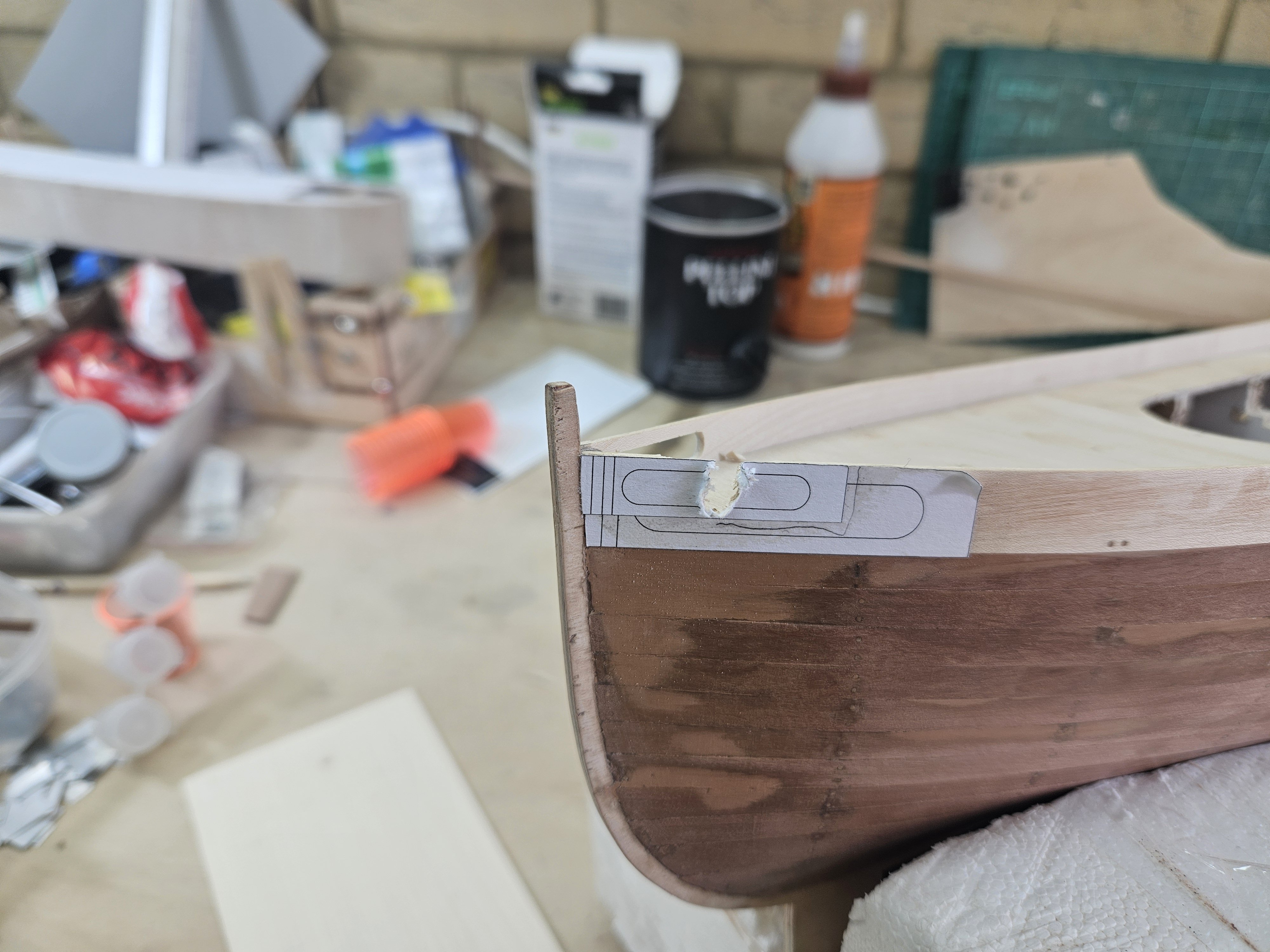
Time sure flies! Many thanks for the visit and likes @Dr PR Phil, I remembered you sharing this and it was on my to do list, unfortunately I had to use so many pieces of wood to straighten the hull that there was no space for a brush, most of the inner surface of the hull was inaccessible. I ll be using epoxy for sure in the future though. So, very little progress to share but here it is: I finished with the propeller shaft housing, it is secured, sanded and faired. I think this was a much more elegant solution than Occre's but also much more difficult. Next I started cutting the openings on the bulwark. One side went fine: The other not, the drill slipped! Trying to see how to correct it, I broke it even more! Ok, no need to panic. It was relatively straight forward to fix it: It has since been sanded and the screws replaced with tree nails. When painted and more stuff added on, it will be invisible. I then attached the rubrail on one side Now the rub rail continues around the stern in a pretty tight curve for a 3 x 3 mm pear strip to accept. I emersed the strip in a pot of boiling water slowly pushing against the pot wall, the strip took the bend in no time. This is all I had time to do between work and extended summer vacations. My work load is going to drastically increase soon, so clearly the most reasonable thing to do is to start another log on an ambitious project - coming soon. Best wishes to all Vaddoc


-
Starting in Rhino 8
vaddoc replied to GioMun's topic in CAD and 3D Modelling/Drafting Plans with Software
My 2 c: I do not think you need any specialised tutorials, just play with Rhino a bit more. There is a command to create surface, one to offset surfaces (for the thickness of planking) and another to unroll surfaces (sometimes useful). Use the command to fair lines but this needs care as it may move lines - useful also to progressively use as few points as possible for your curves. The lines need to touch for a surface to be created but lofting does not need to be perfect as the wood will correct lots of imperfections. Using fewer curves for surfaces is easier. The curves that do not play ball can later on be projected on to the surface - there is a command to project lines and points to a surface that is very useful. To create the hull surface, you need to have defined the sheer (best created from two lines/views), the keel rabbet, sternpost and stem. To check for ripples and surface fairness there is the analyze surface command that contains surface analysis tools. You can also import plans and lines, scale them appropriately and use them to trace lines and then position these to the 3D space. I think you are almost there to be honest. Best wishes Vaddoc -
Planking
vaddoc replied to sgrez's topic in Building, Framing, Planking and plating a ships hull and deck
A way of planking boats and ships is to mark a straight plank somewhere in the middle of the hull. This way the planks above and bellow will not have excessive curves during spilling or in your case will not need to be bent sidewise too much. -
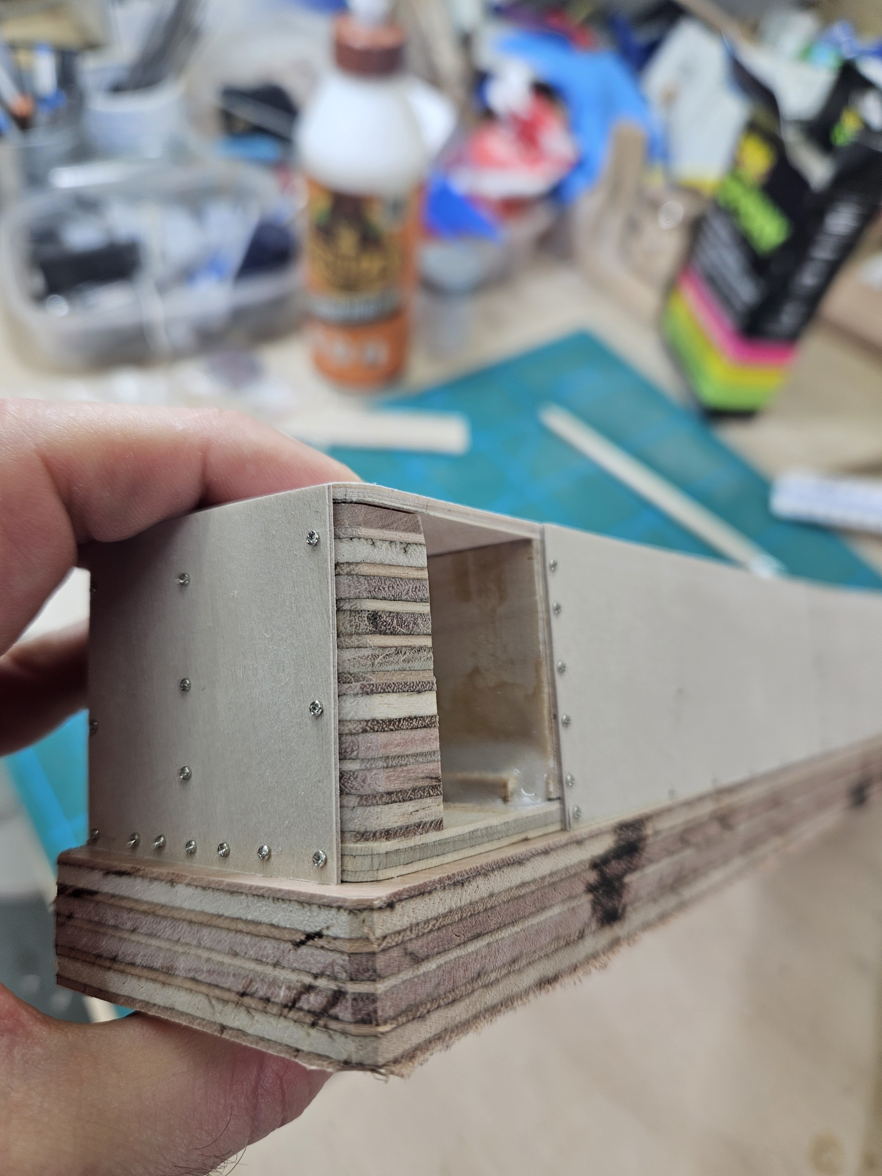
Yes, this would have been a better alternative but I always end up overbuilding things. But I may have gone too far with this! What is not visible is the epoxy I added inside afterwards to glue the plywood walls with the frame...
-
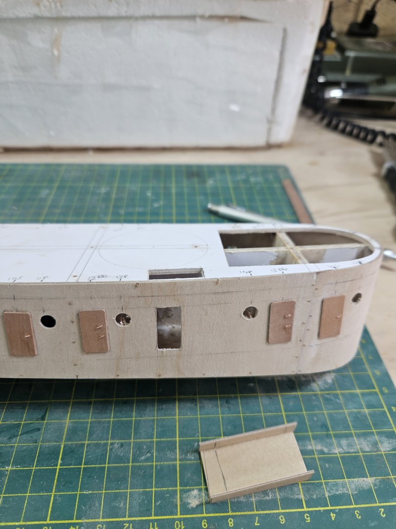
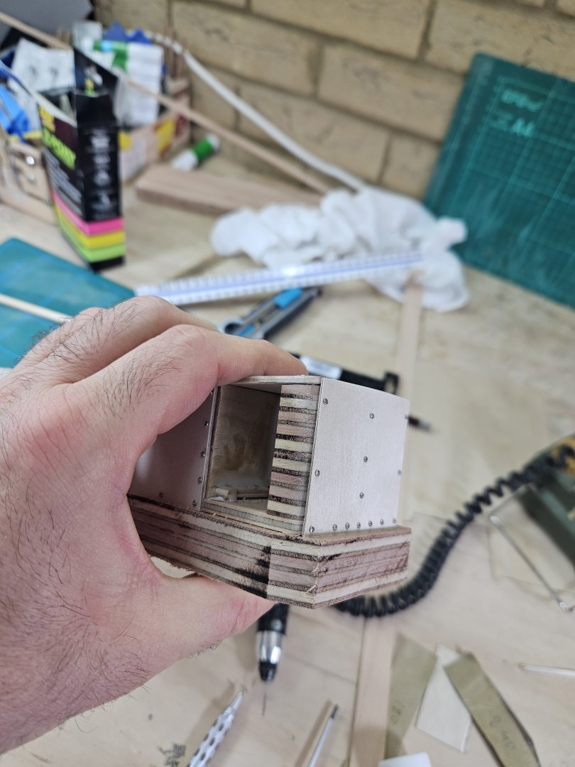
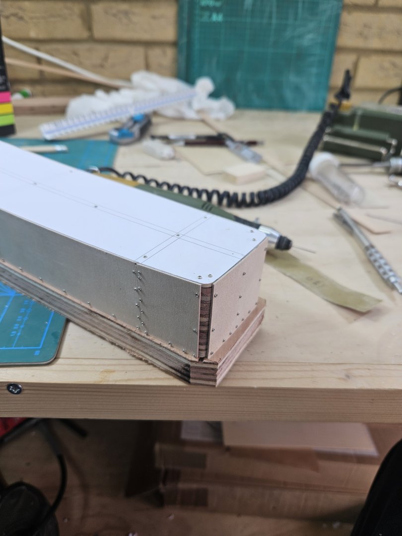
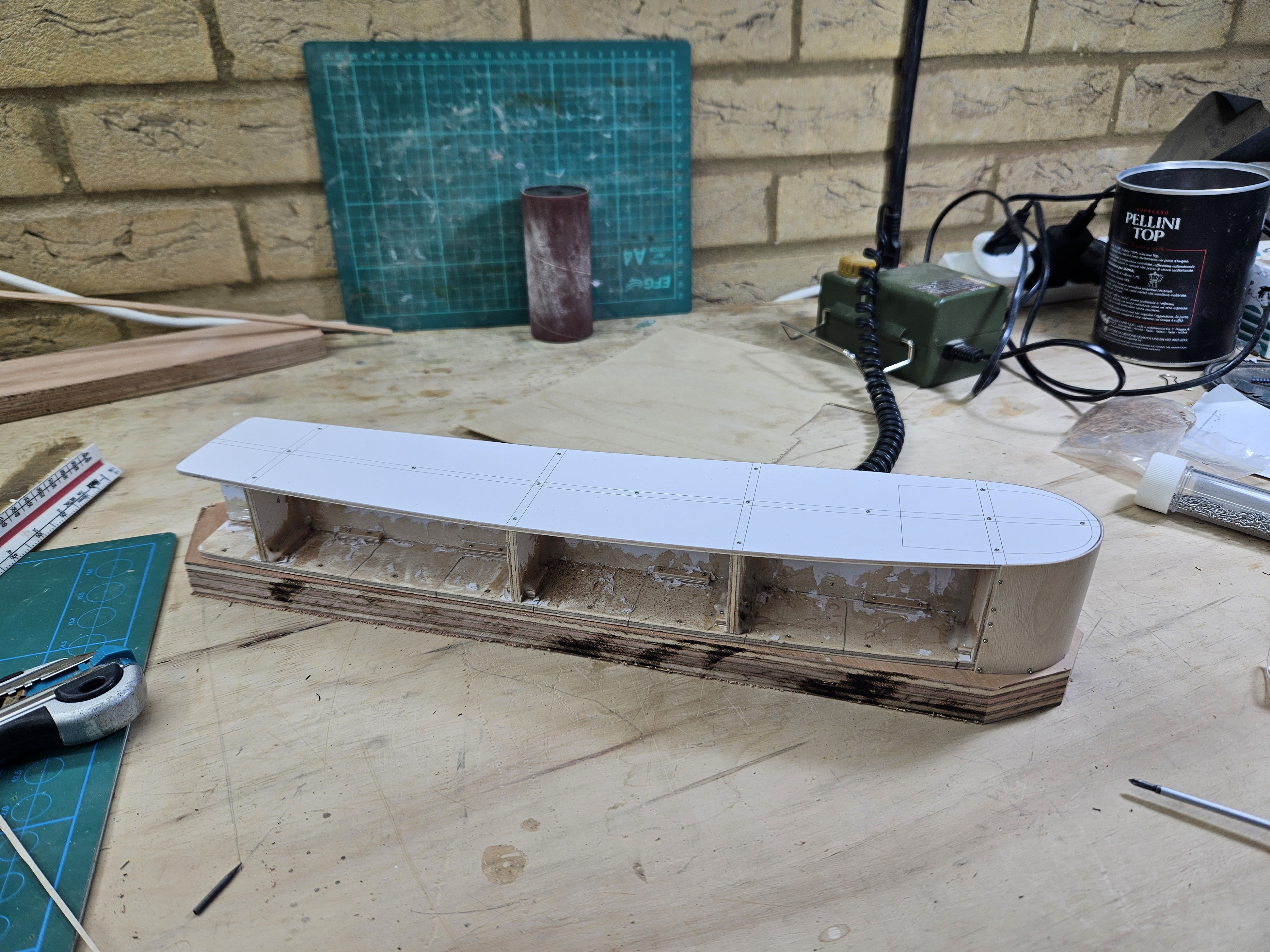
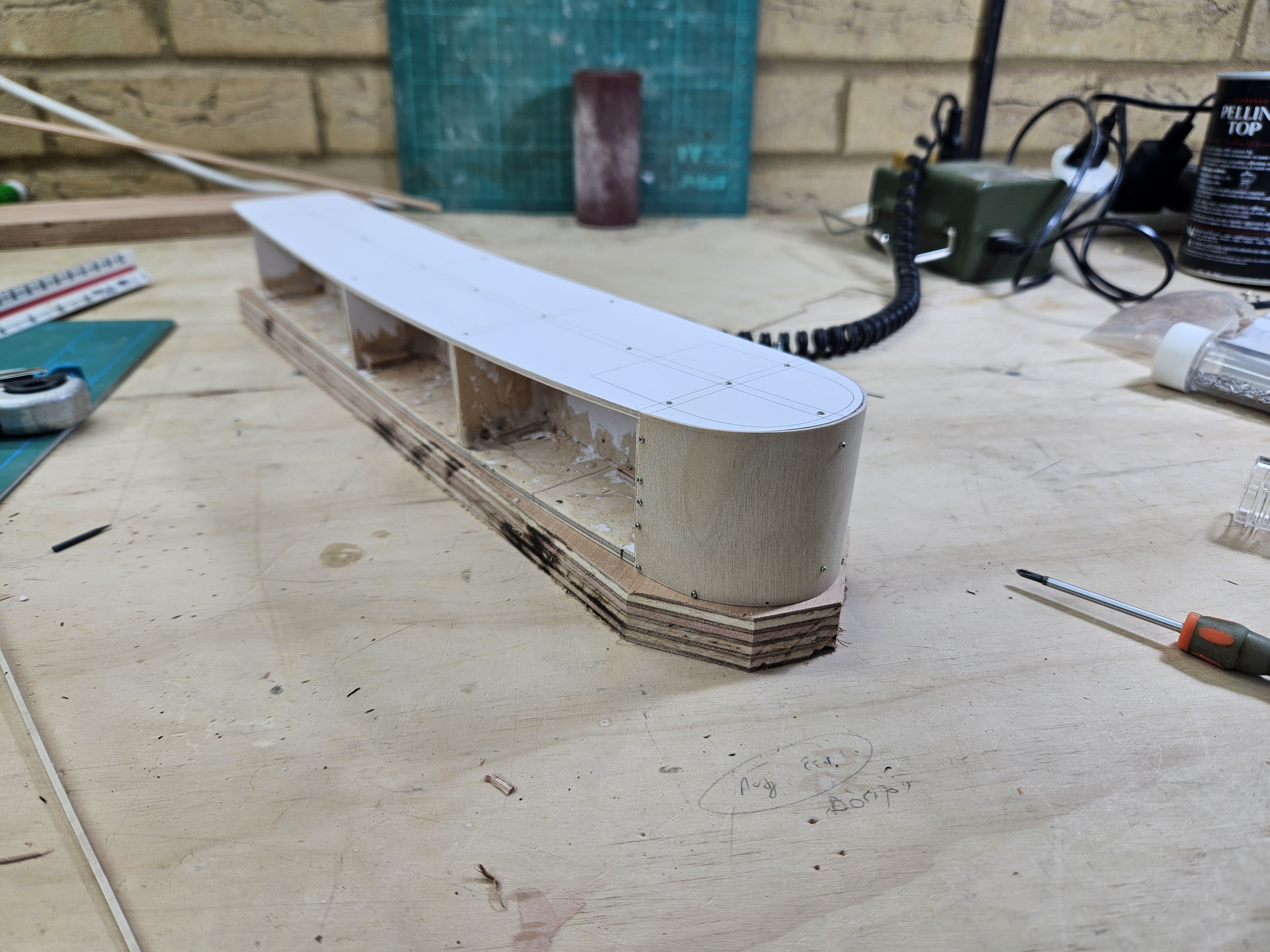
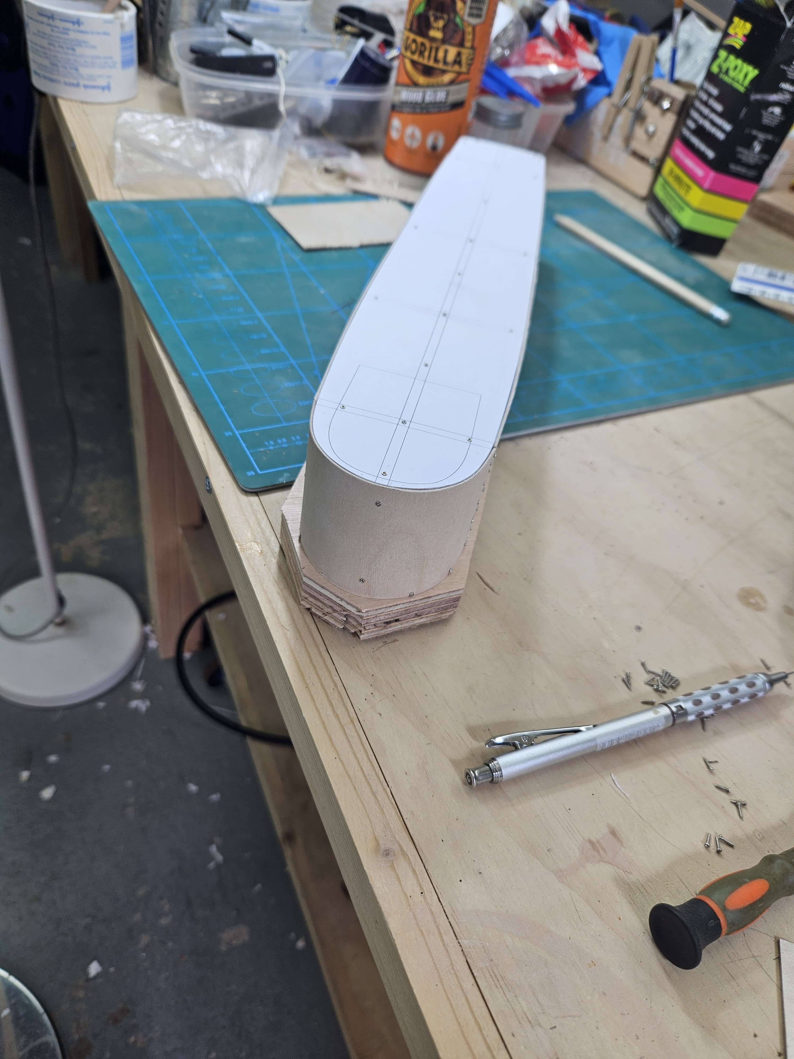
A wee more update as I did a bit more work on the boat - I must admit I am having too much fun! I previously admitted that I shamelessly read the building instructions from Occre of their Hercules kit to get some ideas. There are a few things that I felt could be done better, in this post I ll show my solutions to the problems. So I left the hull on the side for now and started work on the superstructure. Again, my CAD drafts were not entirely correct but at least the templates for the superstructure inner bulkheads were spot on. However, the plywood started warping so I screwed the bottom to a very thick piece of plywood and used screws and epoxy to make it rock solid. Now, Occre uses lots of thin vertical pieces to cover the forward part of the superstructure, blended together afterwards with filler and sanding but I just bend a piece of 1 mm plywood. Another area were Occre used multiple thin strips is the two aft corners but I just made two pillars with stacked pieces of plywood - the small gap will be very easily filled with filler. Hercules has a very distinct propeller shaft tube thingy, this is a feature that a model must have. The solution from Occre is not very elegant, just bending a piece of wood over a tube. My solution was different. It was actually easy to draft this in CAD and looking at the drawing, it seemed doable to sand a half dowel to sit on the hull. Indeed, it worked well and was surprisingly easy and quick. The screws will of course be replaced with wood nails, maybe even use a bot of epoxy, then filler and sanding - I think it will look fine. Best wishes Vaddoc


.thumb.png.3e7061d68b07c9459778ca3c6c982a7b.png)
.thumb.png.9aebc876ceacf99e7608be4e84ca0c15.png)
-
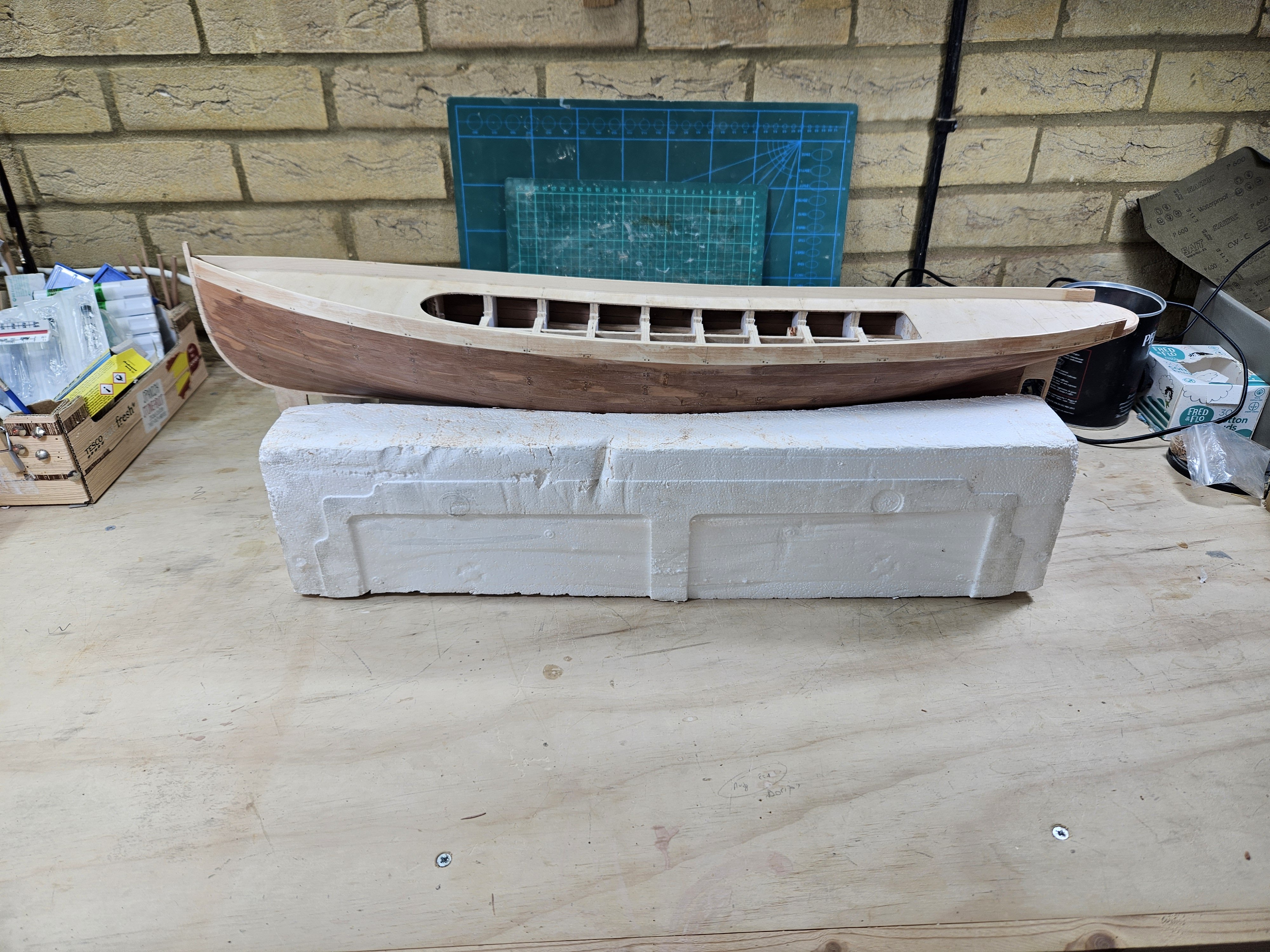
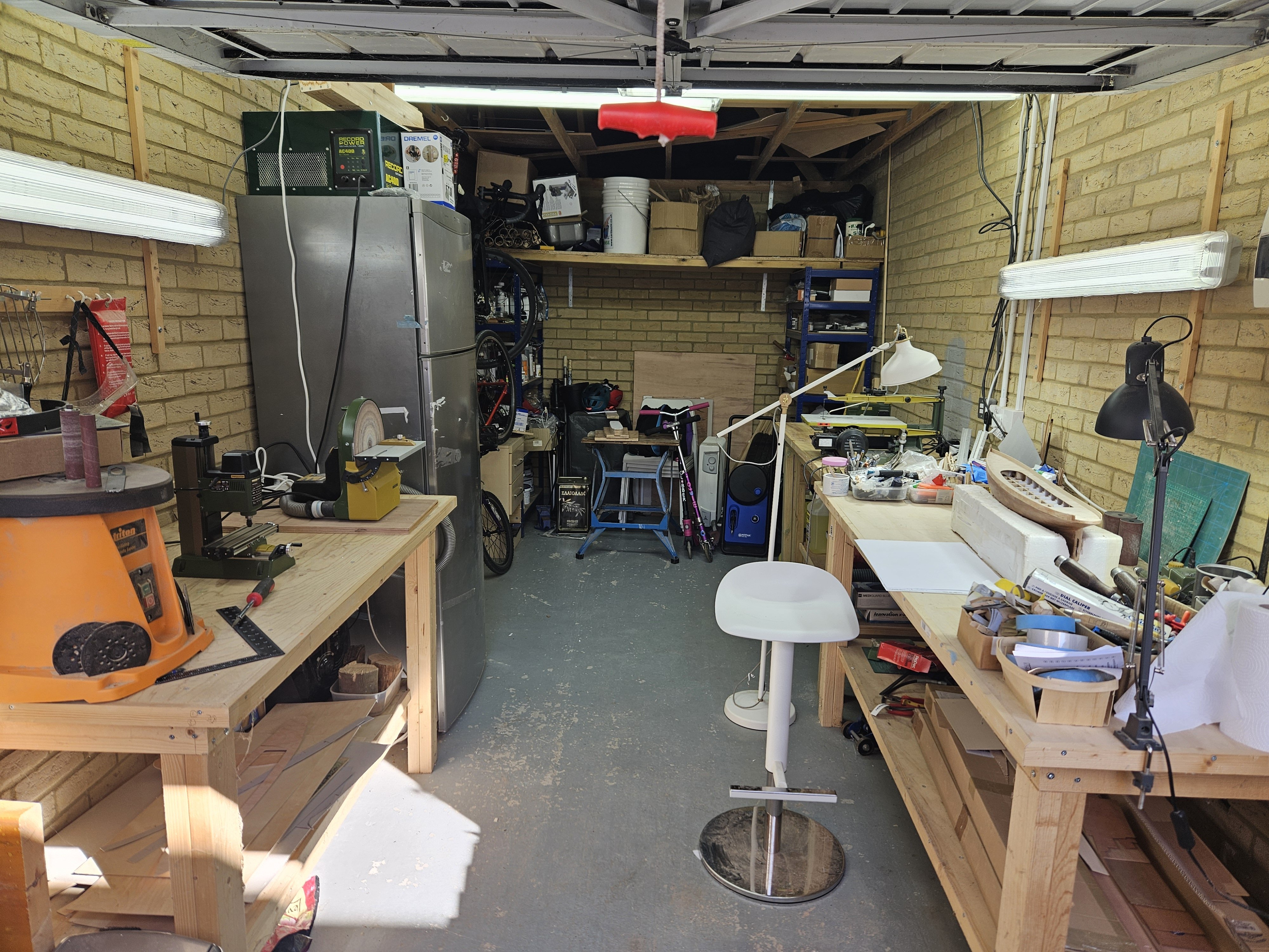
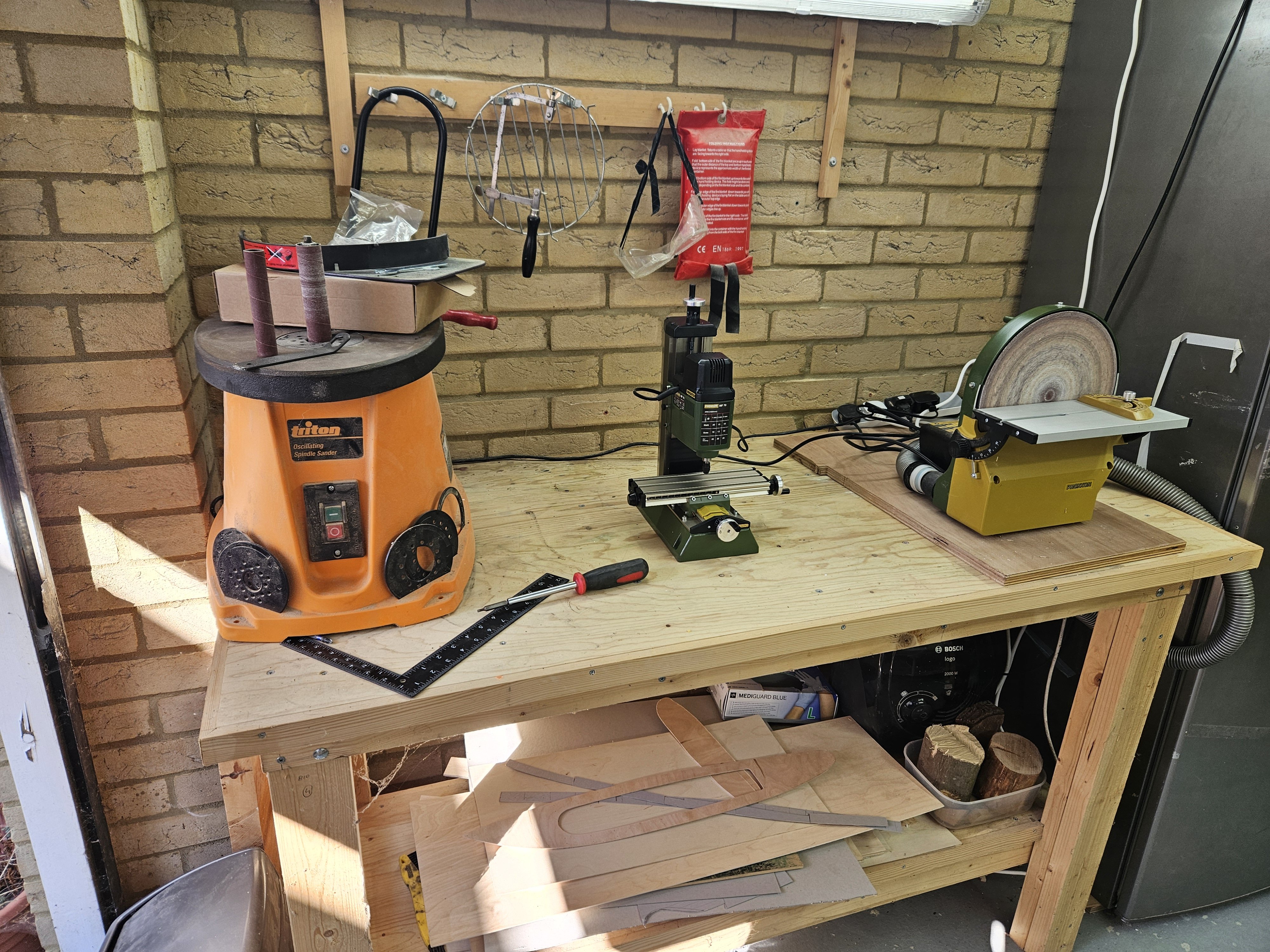
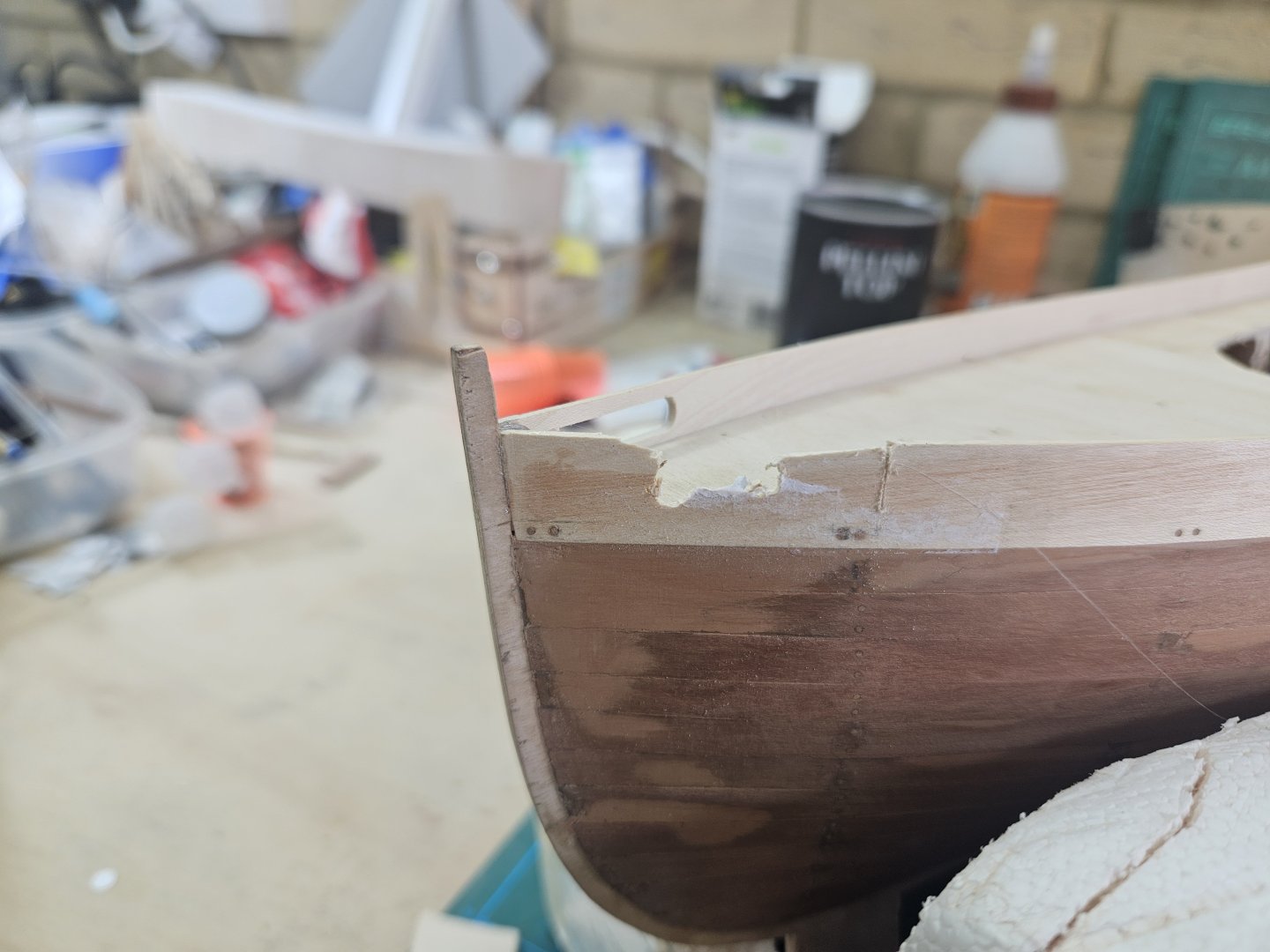
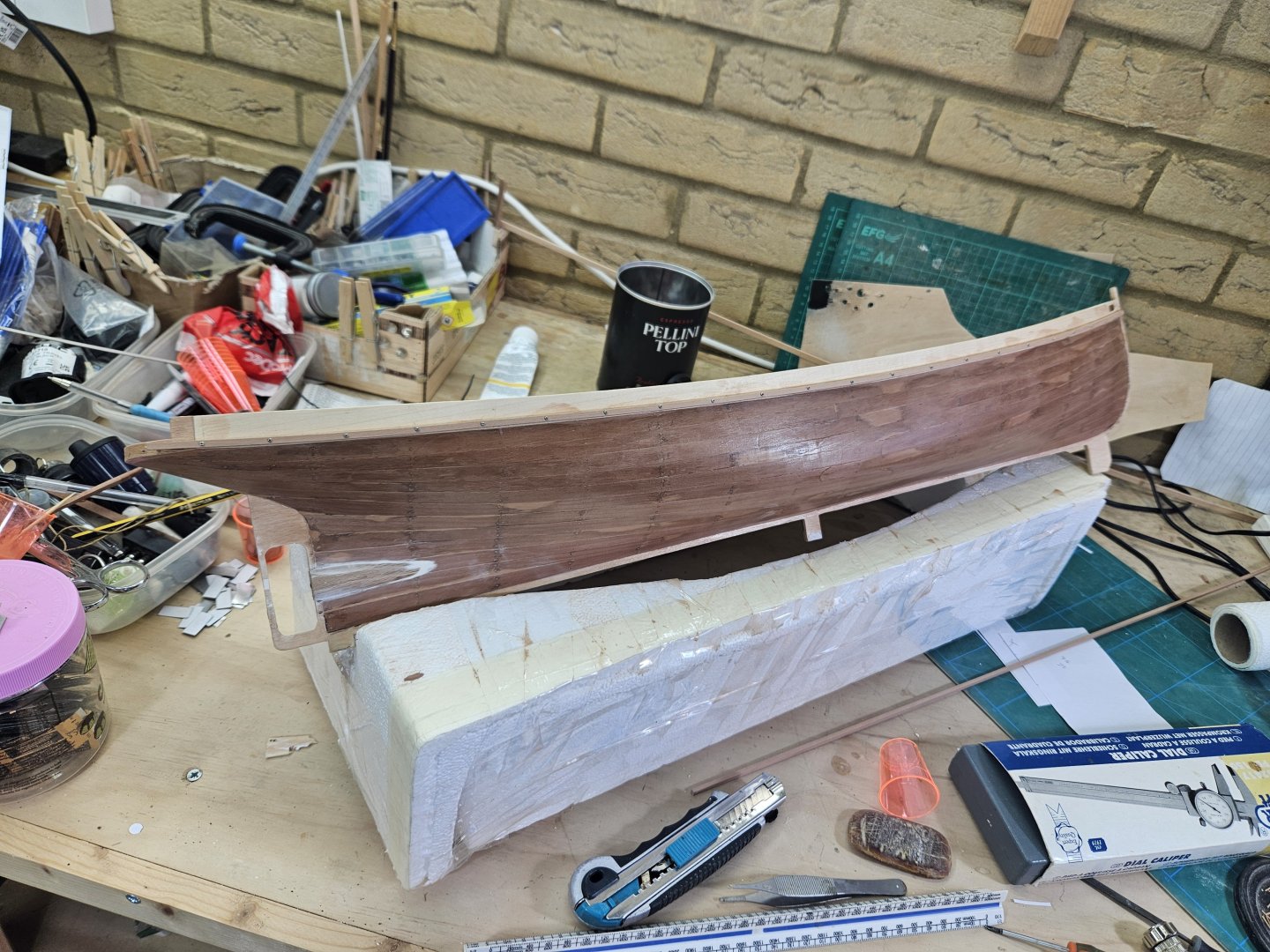
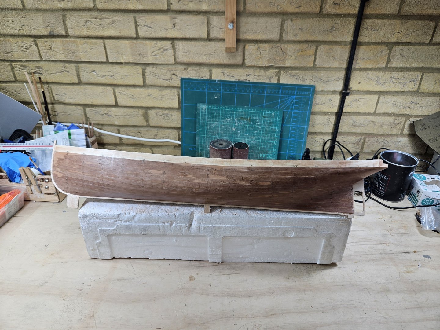
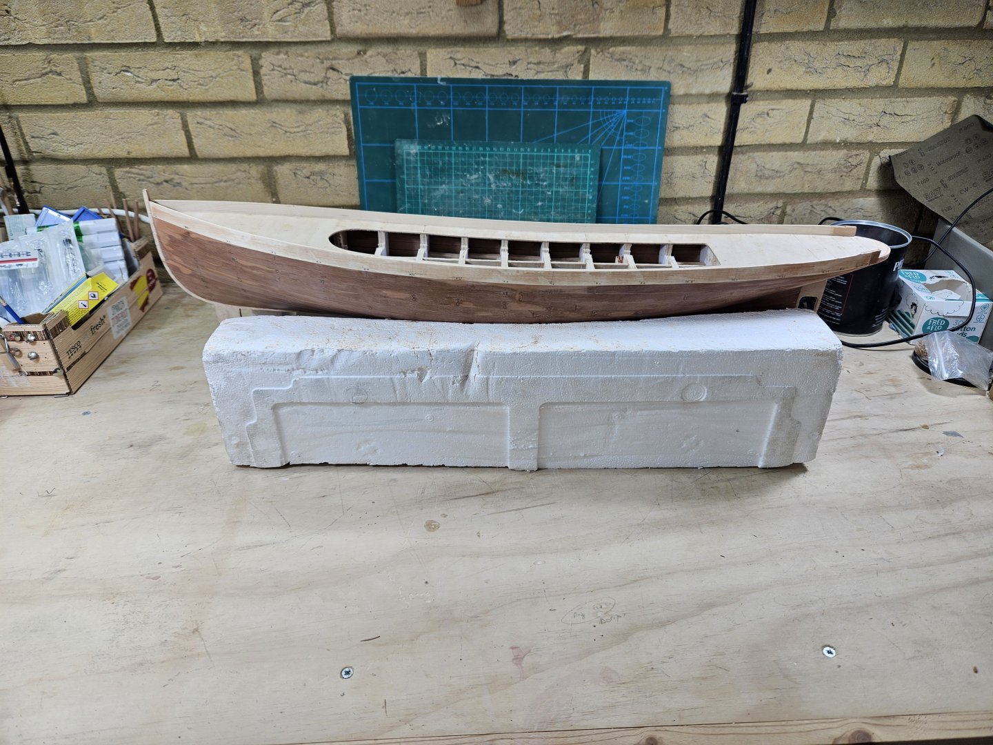
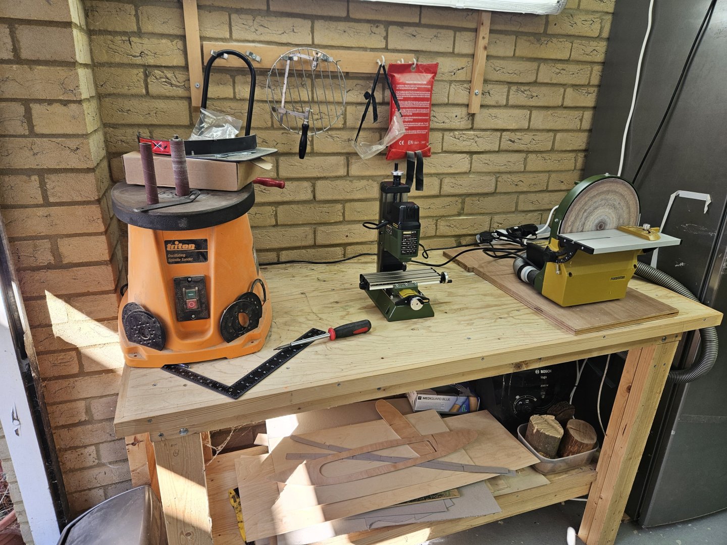
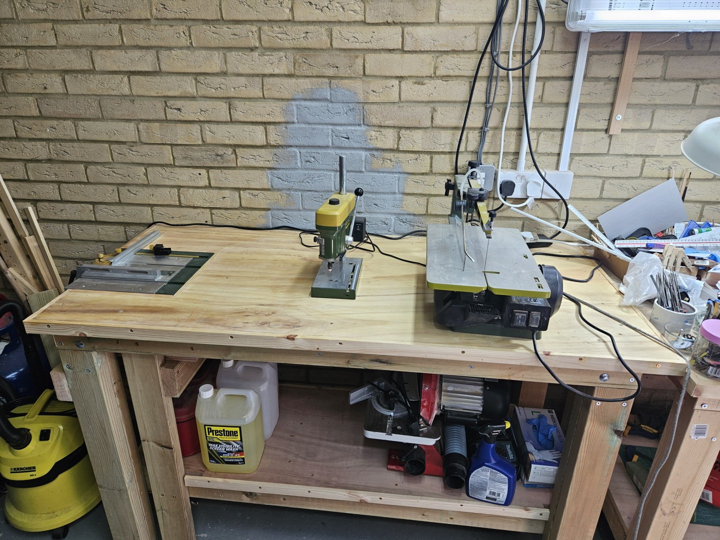
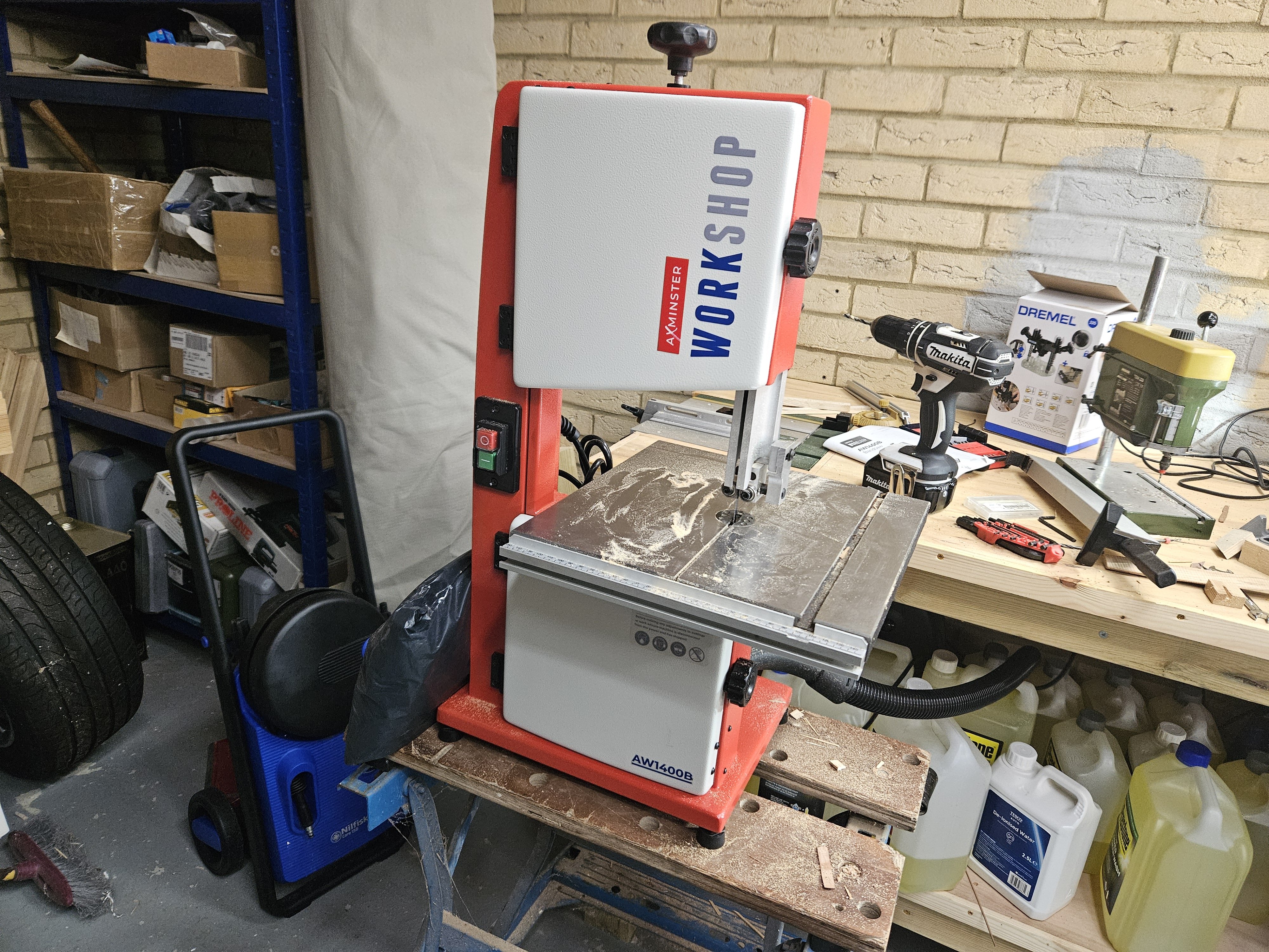
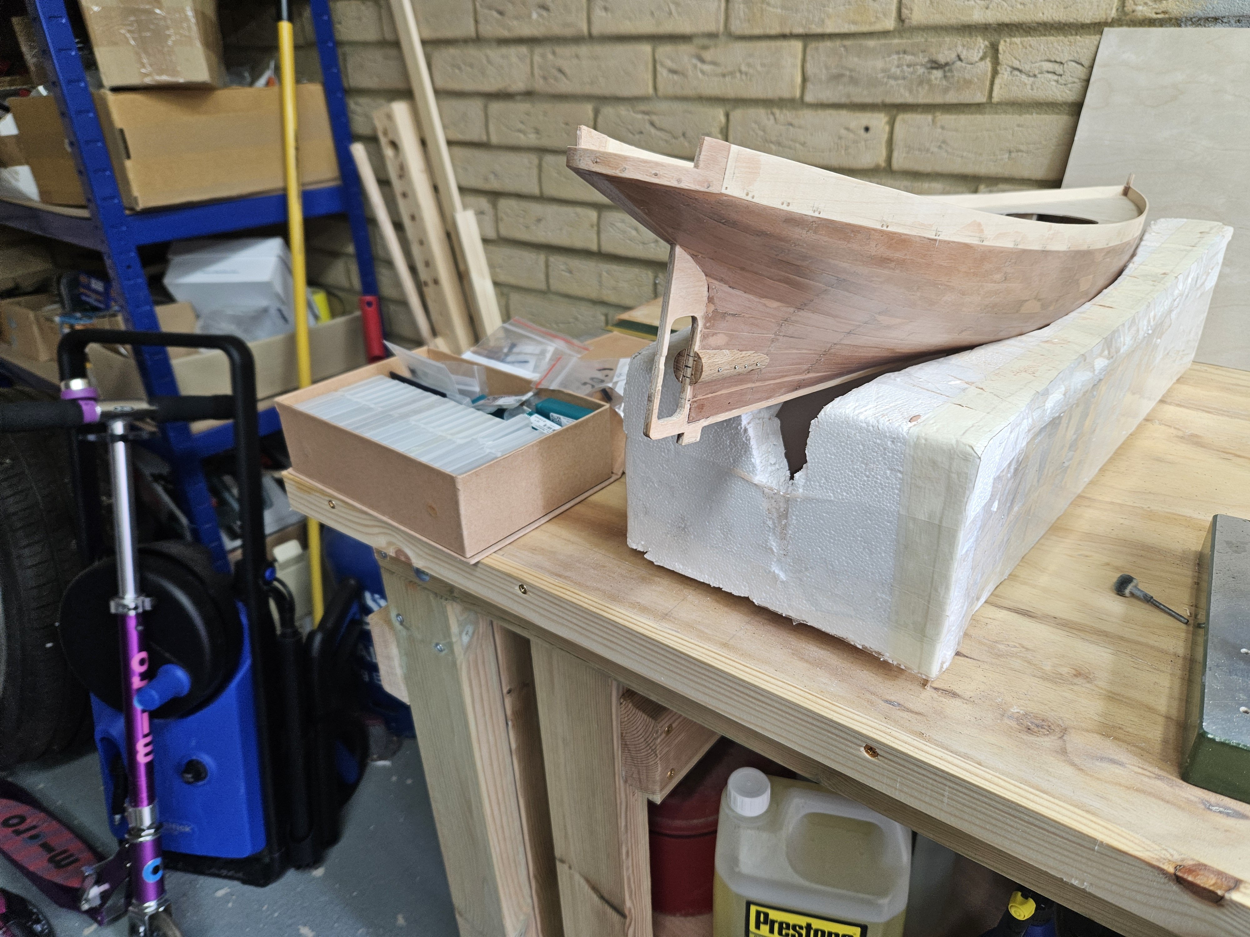
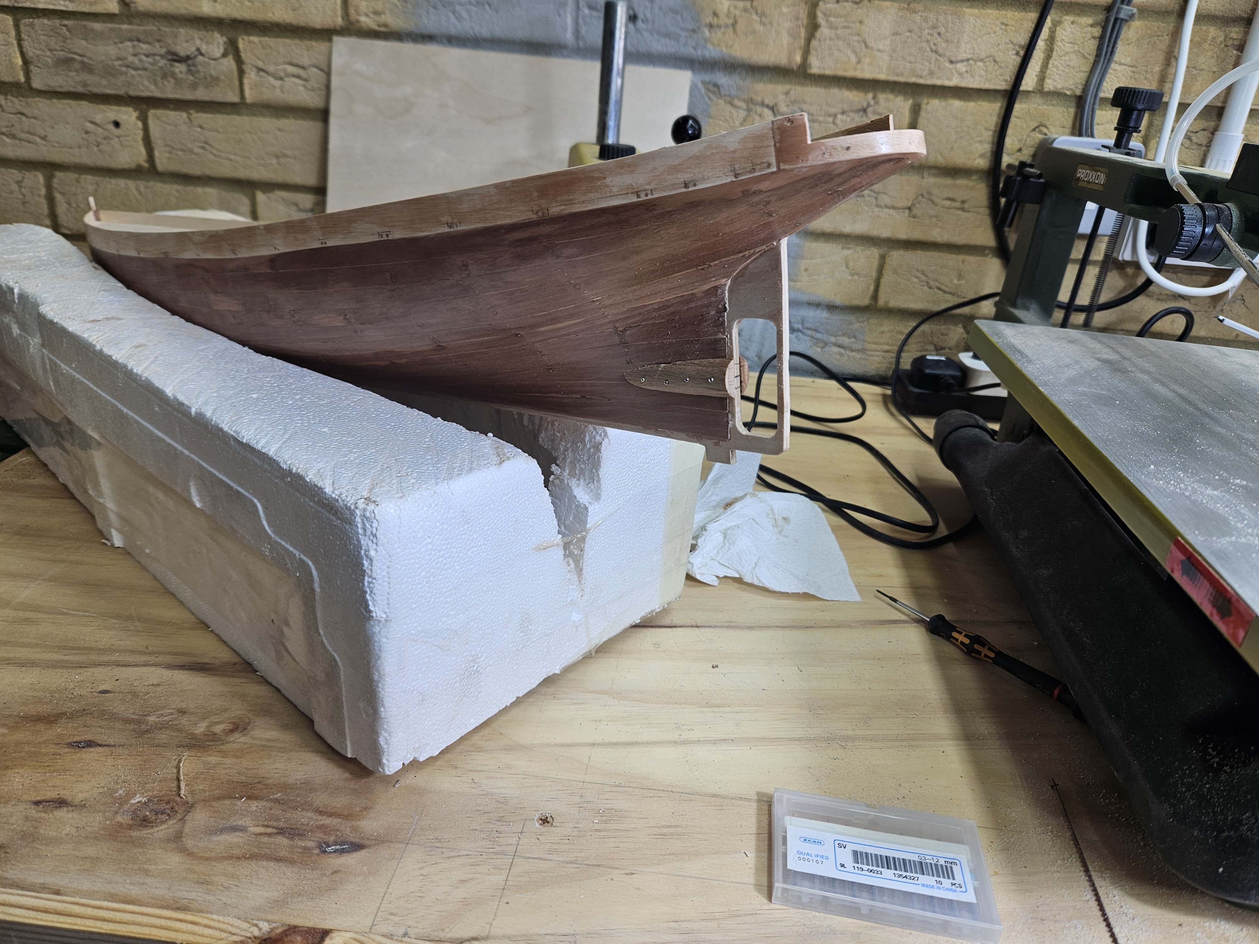
Many thanks to all that hit the like button. @Jim Lad Thanks John, really it is a very elegant hull! @Bedford I had a bit of a hardware issue so suspense to be prolonged for a few days - I suspect the boat will appeal to you as well! @wefalck I did think about this and I have half decided to leave this out, for two reasons: One is that I do not like the plating which is random with a large curved belt along the length of the hull, such elegant lines deserve better. Second is that I ve been fighting cracks between the planks, I ve already filled and sanded three times but the planks keep moving. Not sure why as the pear I am using is very old and dry, perhaps I have not used enough frames. In any case, the plank lines will show no matter what I do so maybe best to leave it as a wooden hull instead of simulating a riveted steel hull. Ok, some more photos: The hull is now filled, sanded to 320 grit, sealed and sanded lightly to 400 grit - then sealed again and re-sanded to 400 grit. I actually intended to use a blade to scrape the hull but I forgot to do it, it would have been faster. Still, the hull is now very smooth. I ve left the little feet to the hull as they ll help to mark the water line. Happily, the stern also came out alright There are several opening to be cut out to the bulwarks as well as some more work to be done before painting This is pretty much as far as I ve gone studying the plans and the boat. I need to figure out the stern layout and tiller mechanism, finish the bulwarks and start work on the superstructure (started already, again some happy accidents in my CAD drawings) In the mean time I cleaned and tidied up the shipyard, thought I d share some photos Sanding station with the new toy, Proxxon MF 70 - not sure what I can do with it but I had some credit with Axminster so chose this. Cutting/drilling station Work bench Take care all Vaddoc


-
Gold solder for brass
vaddoc replied to Richard Braithwaite's topic in Metal Work, Soldering and Metal Fittings
These seem to melt at 900 C, whereas silver solder paste is between 600 - 700 C. To my experience, to reach such high temp a larger heat source is needed risking melting the actual piece. I actually had this happen a couple of times.
.png.6544133df801be0130d8f4d7e2faeab9.png)
.png.2a41240cd5531d09853ca66c71df5afd.png)
.png.1b5f46c32b911b9c902fa8feb02ecf32.png)
.png.a9bd655a0af47cc697865fb12983d953.png)
.png.6a6ca17c1dfe01fa9bd48b6925ad9a02.png)
.png.a197ed9c1537908f870e07d5231d7141.png)


.png.9af876d7fe5208e3c670b812b454941c.png)
.png.cc3b73d4cde90938eb2dea3a158e2dbe.png)
.png.15609c0af170920fd69ad23568d29722.png)
.png.726abaf4d5f9870ff8710cb0d1b652e6.png)
.png.9b67c69a310c3cb9b78064b595e47ec4.png)
.png.3abcfaae576e2c6a5910df41d75aee12.png)
.png.98f872cff53ae0a1b1ecca4c9f3041ae.png)
.png.028e46ebb1017b7708616d6a3ade3297.png)
.png.7786f965cb773ab209b64d059bd5bf38.png)
.png.c9fb1d528bbffbca723f43f3927a799b.png)
.png.b484eb16fe589e1864bb36b8bbfc296a.png)
.png.05380926f00fd91b0d4bf9257e79d142.png)
.png.547cbecee5d740f4f057d4d1a741f8fb.png)
.png.7674ac1759811074b284aad9acae545b.png)
.png.d84bd4940301fa93e591cab5a7f49fa6.png)
.png.96040d947ad3d062307c12de4f2e73ba.png)
.png.5f2002be585f38164e38eb18f7a6638e.png)
.png.35bcfa2559ed0d254168d91bf691da6c.png)
.png.93c22ca9b8998690837c4e13e93c1b1c.png)
.png.b0f187c75824b4257e6381a88ce79d71.png)
.png.12a45a74a7c2013832a49d01ec1778d6.png)
a.png.7a63e3da8b6747d5312ff58b6b1b8505.png)
b.png.3872c7576431649dbf3710187891a933.png)
.png.a0e54dd73905517619857c992765ba7b.png)
.png.9c597864aa989841d38f66878a79998d.png)
.png.1c246e0f936128ae824691930328ddc4.png)
.png.6f280d47078cdf4b752bf0423982adb6.png)
.png.06911784622f7d3b55e55530bd4c60ba.png)

.png.6b2984f9e93902c455d51b6f50c400f2.png)
.png.0c647262be4683f46e597bb68c5160a0.png)
.png.0402d4b2bec4cb7c009ac7448cb3aa99.png)
.png.fea8436e48c0b316d99bcf7053a6d5c2.png)
.png.18cc80691d6e345704b70d5729af87ab.png)
.png.08145bf2634e9d4eee0741860e0d92fd.png)
.png.1e3a6ed5b62f450e6ede92473d170343.png)
.png.1656d42df093c8f7986738a4ca273e62.png)
.png.da712bd9133106f78927a6c5ac7a86e3.png)
.png.cc3a7c7402c8dee9e4afc59625a0efbe.png)
.png.f52583141f0b99f28a714cf5d9d75d60.png)
.png.49cf60ede217e0ba1b01e755acde9a56.png)
.png.4642fb56f5154bd7fc1ac9bf2d26dcc3.png)
.png.aa4ca714d2026c8bbdaaa51e6e9c24da.png)
.png.aa8b8f641ac8ade7df4d9d174a1dab94.png)
.png.b5e4fea8f517972544fdd94b53ca605a.png)
.png.4a65e1782e109911d20319b777f37c77.png)
.png.1553fef65500863960feb44a69b5db84.png)
.png.23c089209a678f768e16ce2f9eca8693.png)
.png.22d94b4b3b2ff485204460b95062a623.png)
.png.f55d95e508c79c233fe162f551a8a467.png)
.png.00357b1b54156f4028545483b3a2f6e4.png)
.png.4eff7f555543a48cb5a41266b7bc2d38.png)
.png.c1ff092c5bddb6f3e9b33803e10cfc69.png)
.png.e71a2ca4df24b96f155b6ac74a800f08.png)
.png.172ce6af14a9b10cd43ad717d2208c3d.png)
.png.8c4597ed9adedd865e7d083293d9a2bb.png)
.png.283091ff35387af6e1056dc2d50f1ce9.png)
.png.256e2324c7a93f0f543c0f99d9d9df9f.png)
.png.64ab6366f2f0cc9659fbc52b4288efca.png)
.png.80d494b6d254b0b2854974959bf97e32.png)


.png.fcda0a594d667d3a63ba4a173e1634ad.png)
.png.6c0ac5f6391cbb0e25be763ad2cc4030.png)