.jpg.f26acc9a74319261612561bfa7da1303.jpg)
vaddoc
-
Posts
1,605 -
Joined
-
Last visited
Content Type
Profiles
Forums
Gallery
Events
Everything posted by vaddoc
-
.thumb.jpg.6fd4c1b78768bb3efd745ab810936005.jpg) Honestly Phil, your CAD drawings are pretty amazing. Regarding caulking, I ve used in the past Elmers colour changing filler mixed with black acrylic paint. Sanding it all off leaves gray caulking lines. A quick wipe with Tung oil (I suspect any other finish as well or Rennaisance wax which is invisible) makes the lines black again. Vaddoc
Honestly Phil, your CAD drawings are pretty amazing. Regarding caulking, I ve used in the past Elmers colour changing filler mixed with black acrylic paint. Sanding it all off leaves gray caulking lines. A quick wipe with Tung oil (I suspect any other finish as well or Rennaisance wax which is invisible) makes the lines black again. Vaddoc- 492 replies
-
- 3
-

-
- minesweeper
- Cape
- (and 1 more)
-
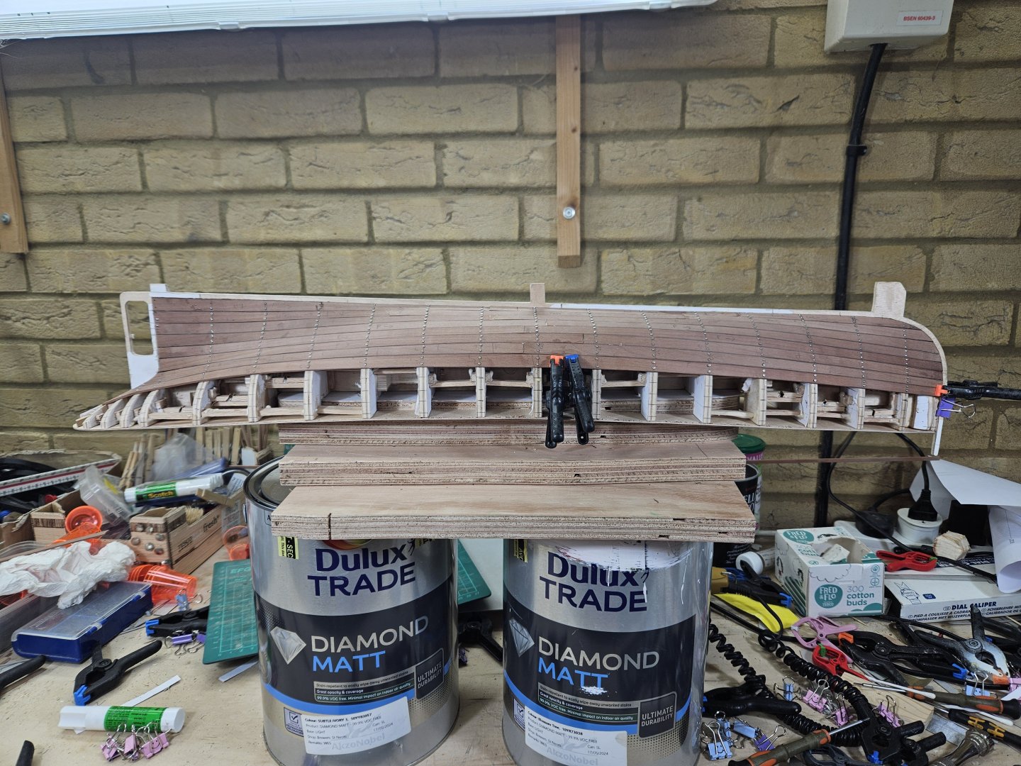
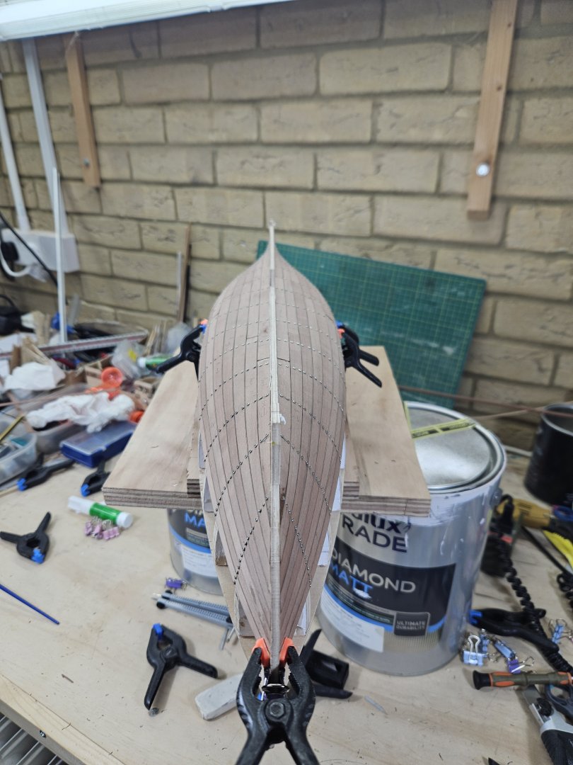
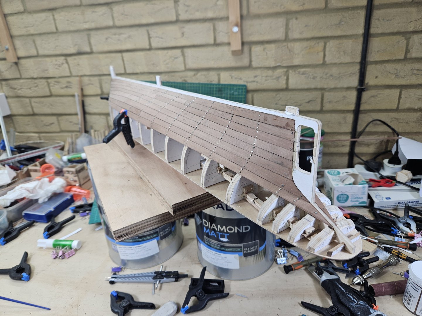
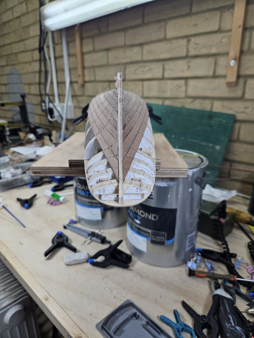
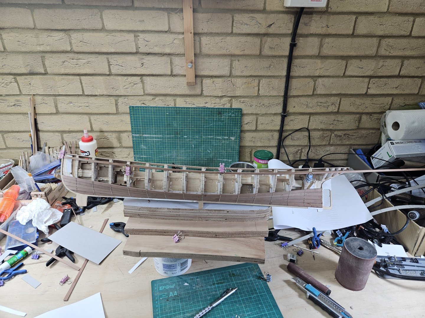
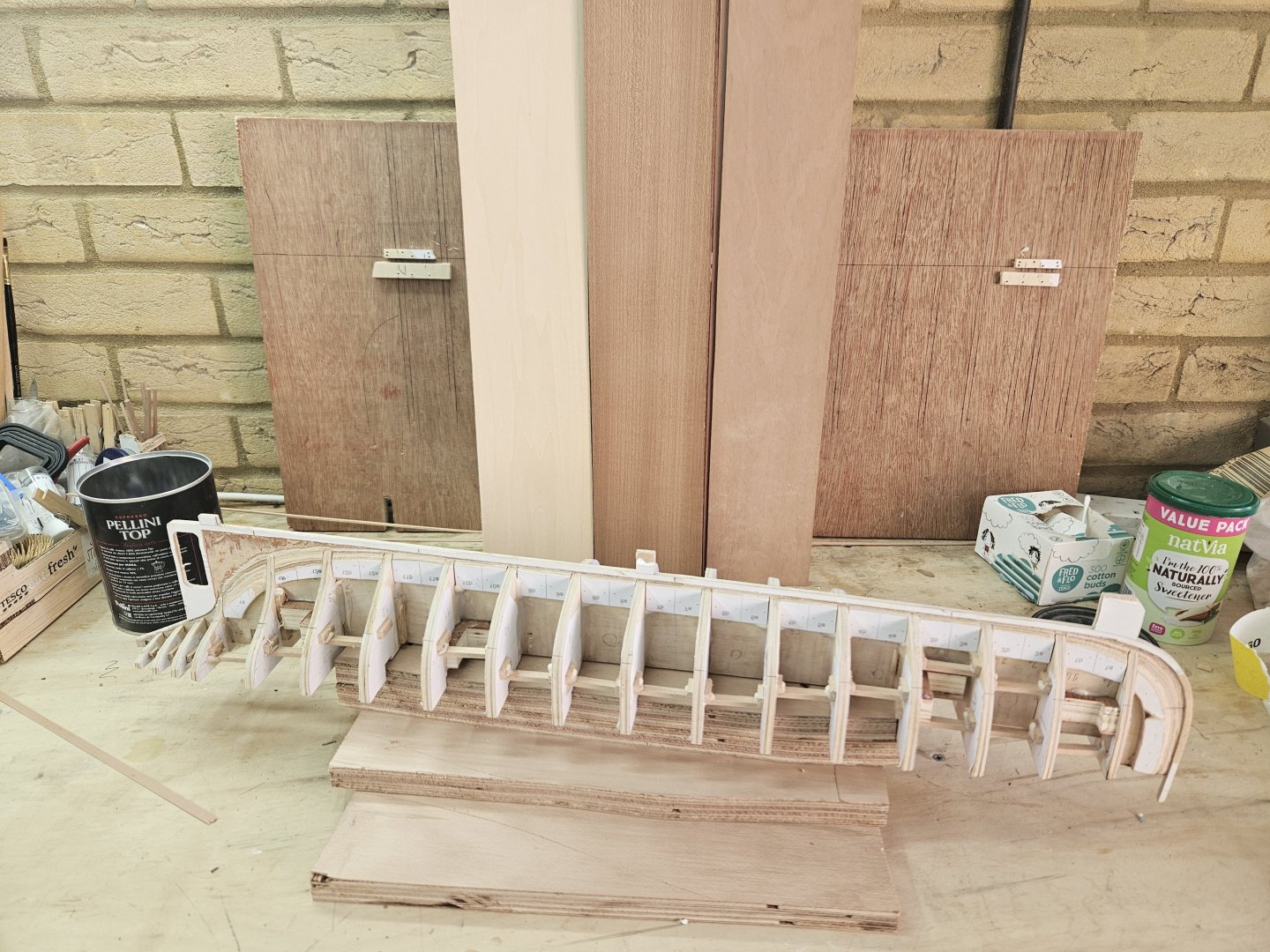
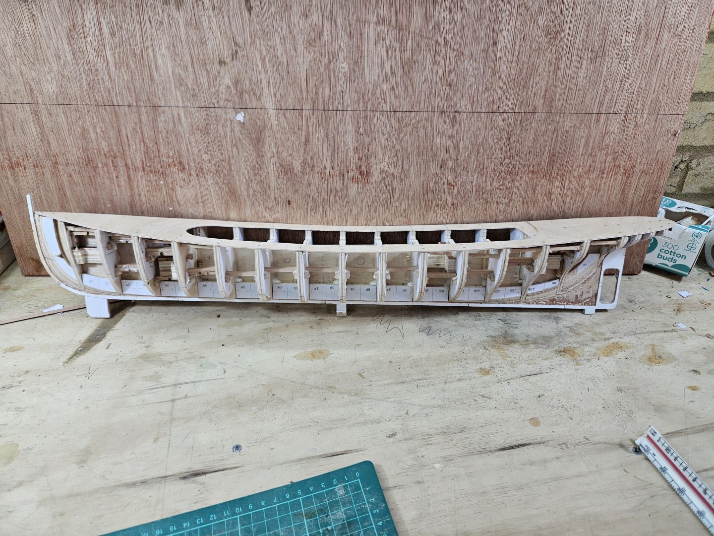
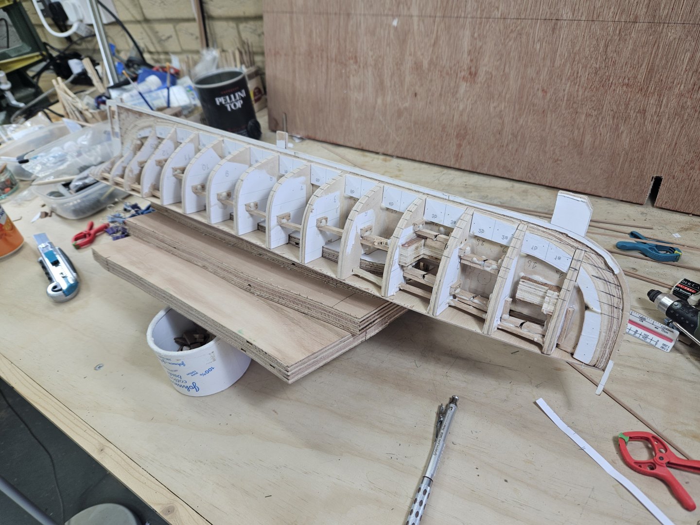
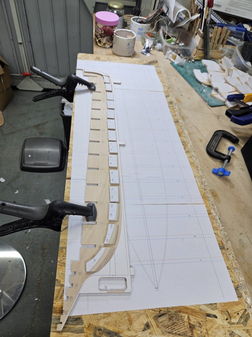
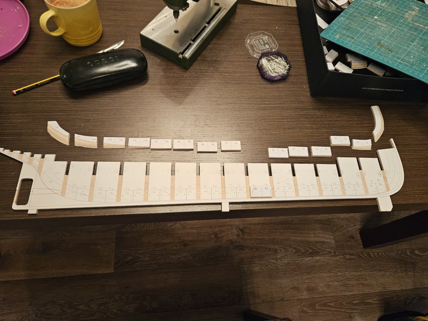
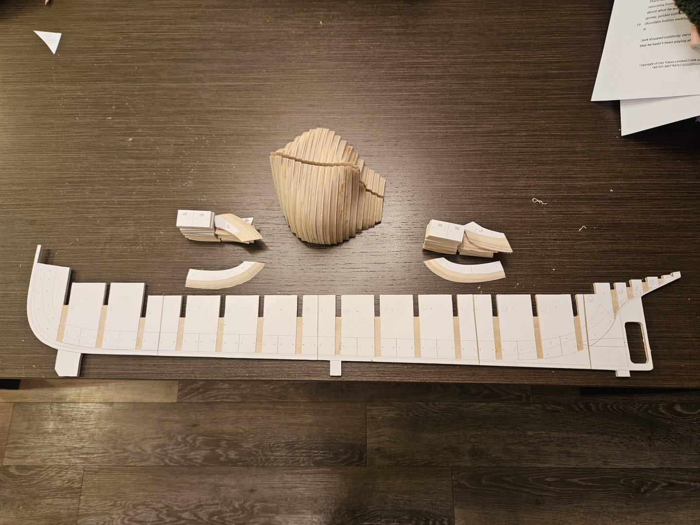
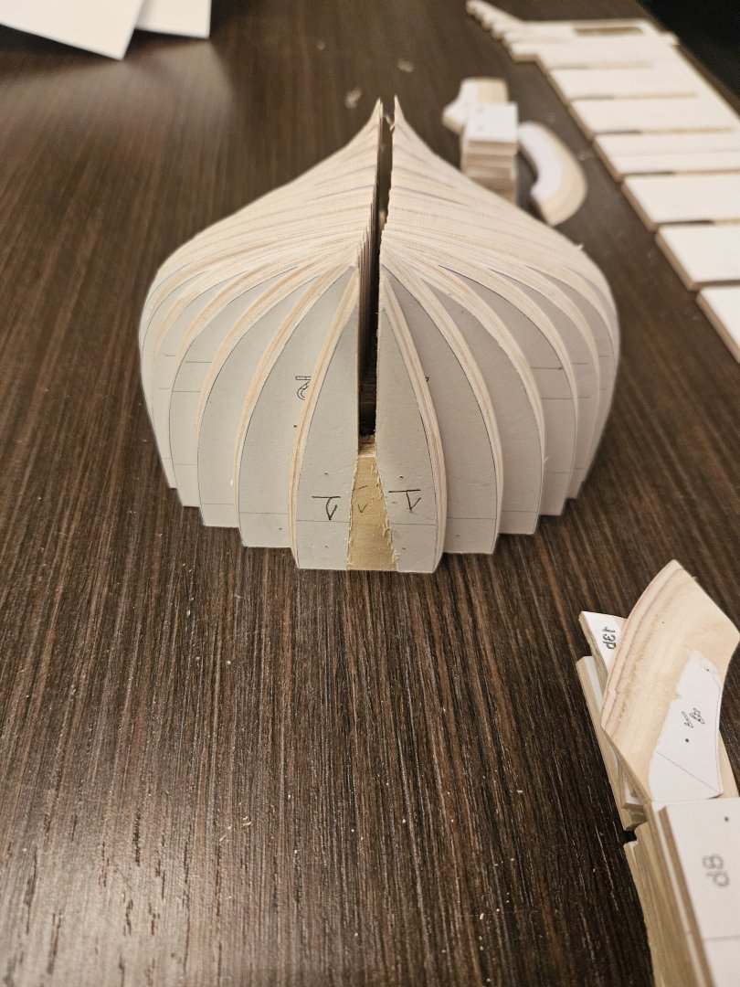
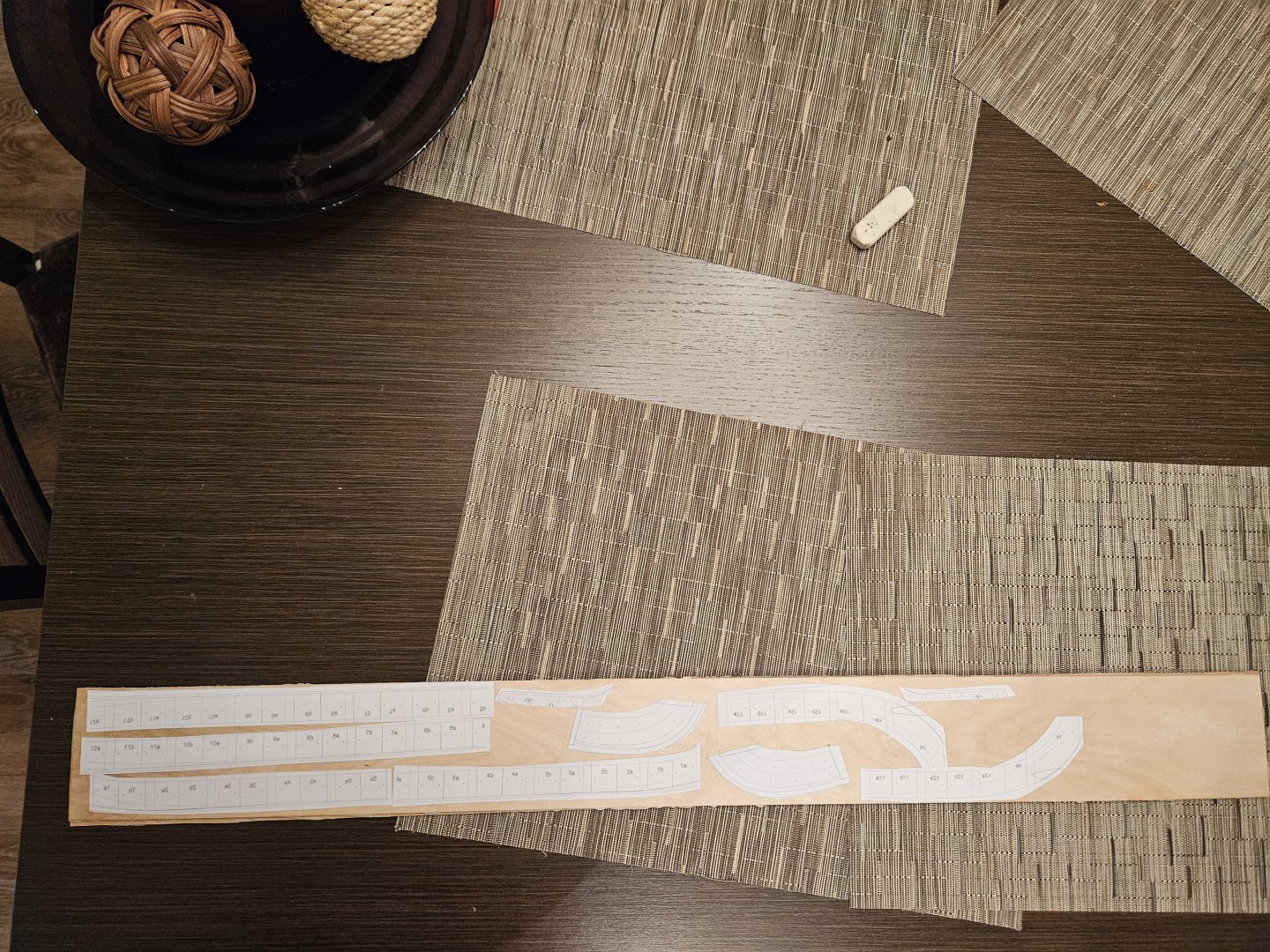
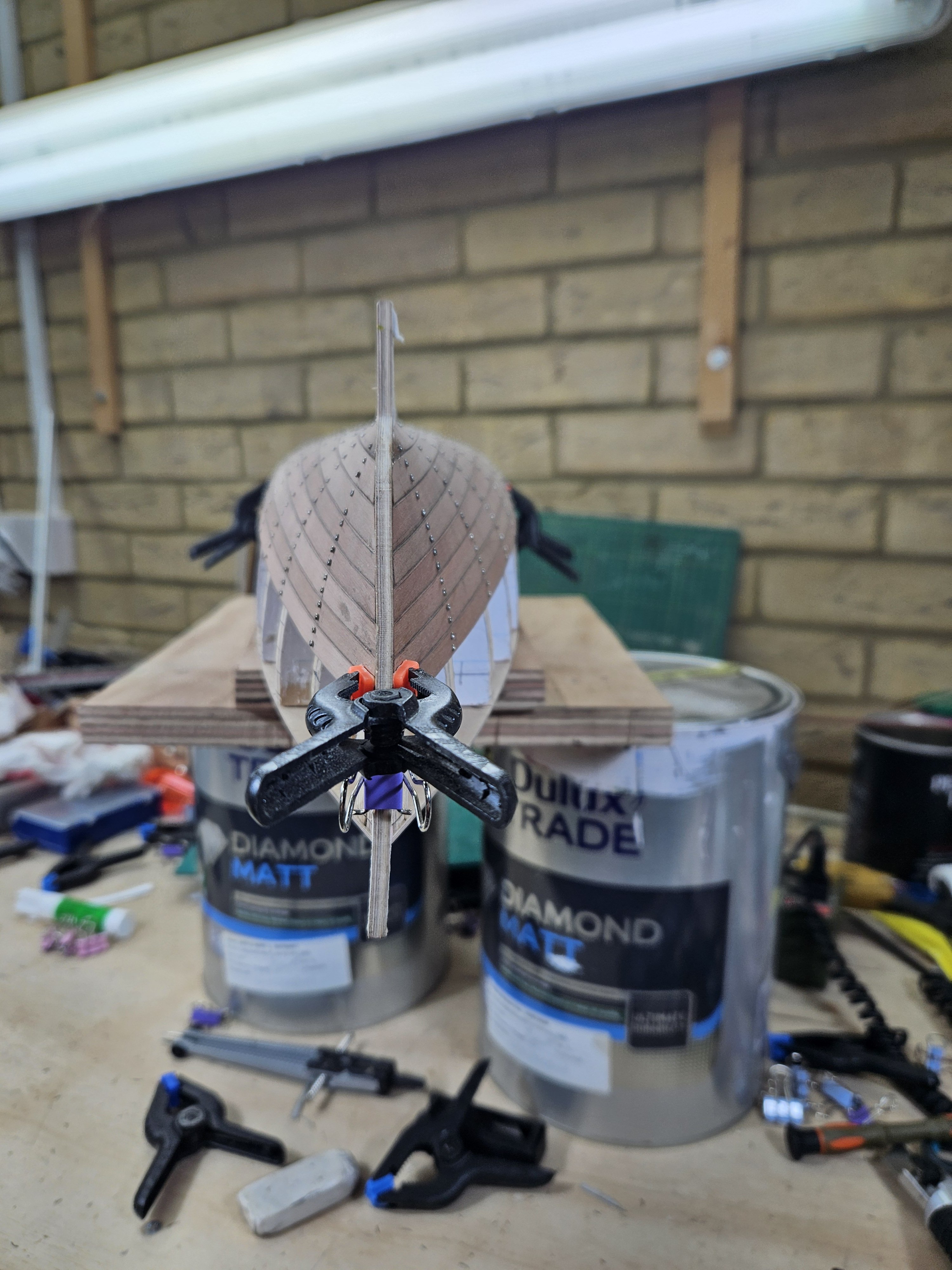
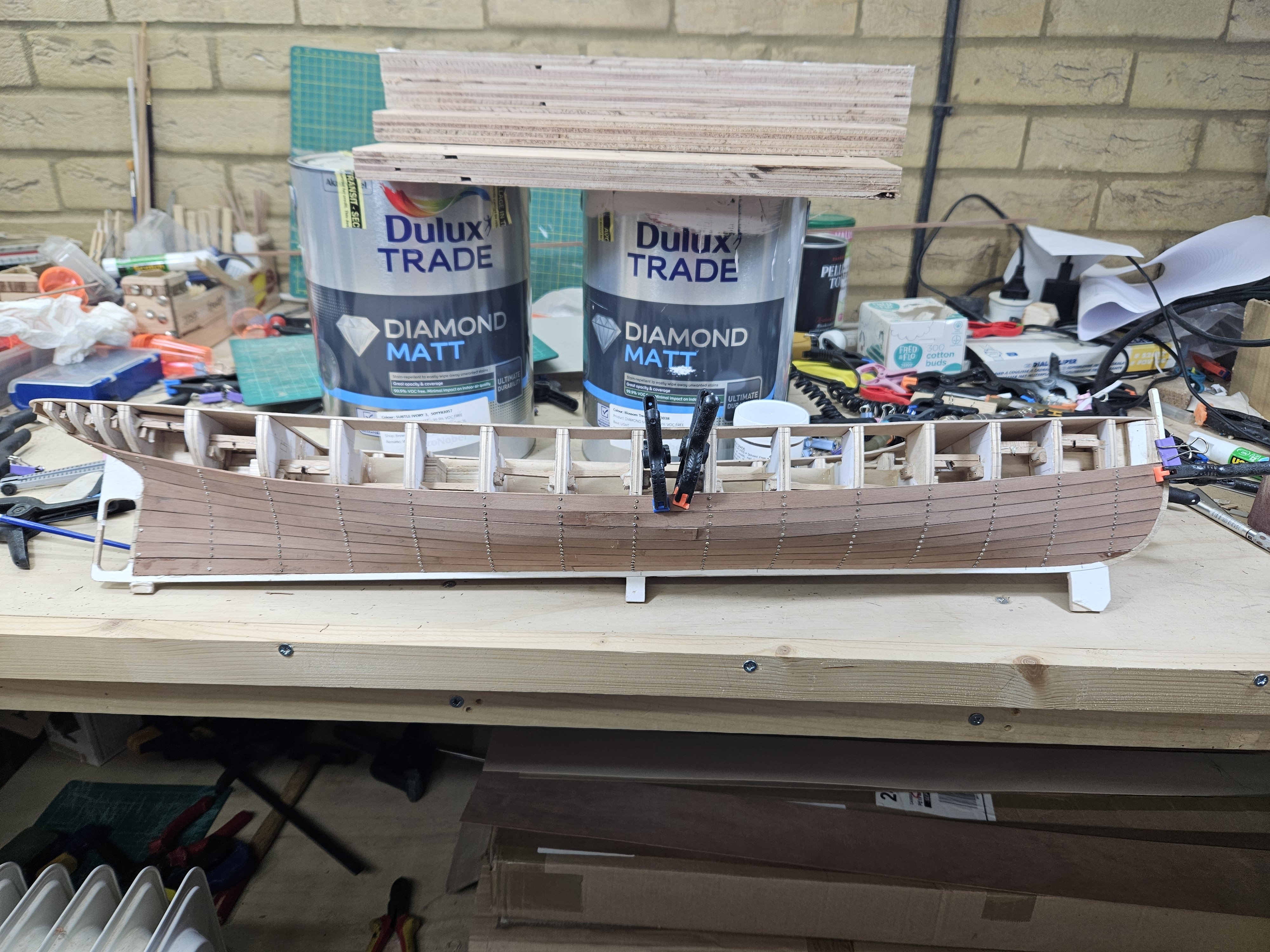
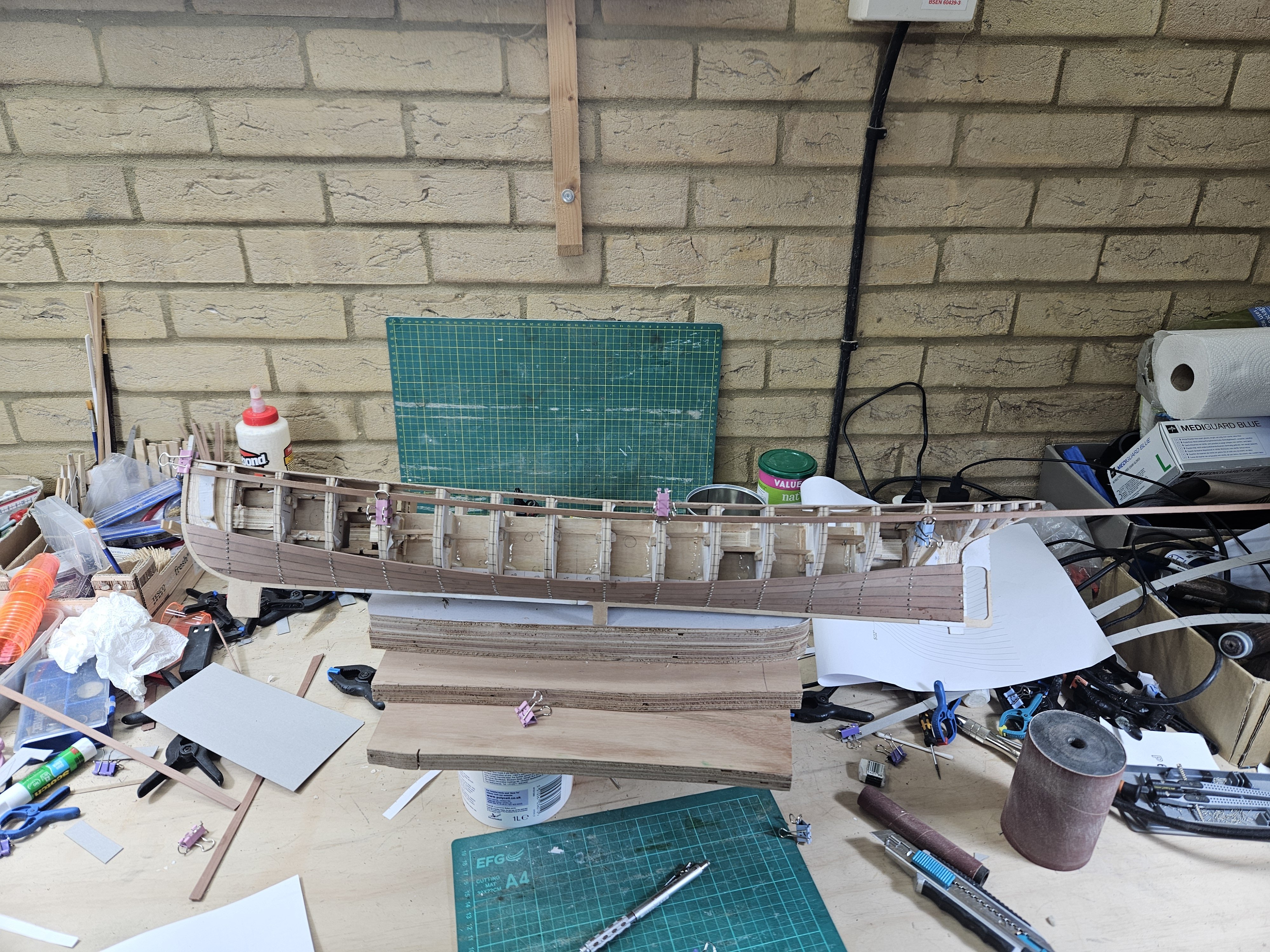
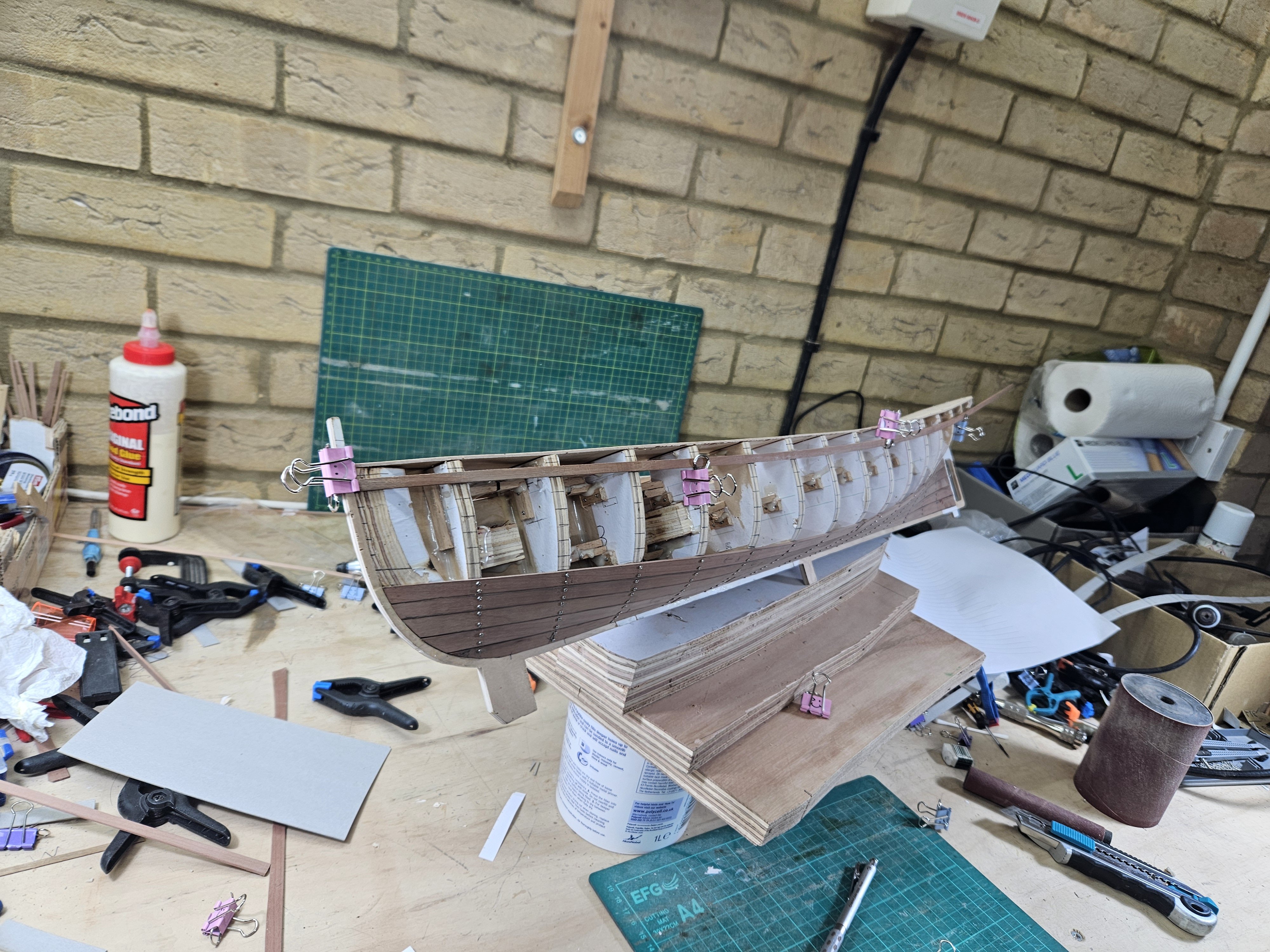
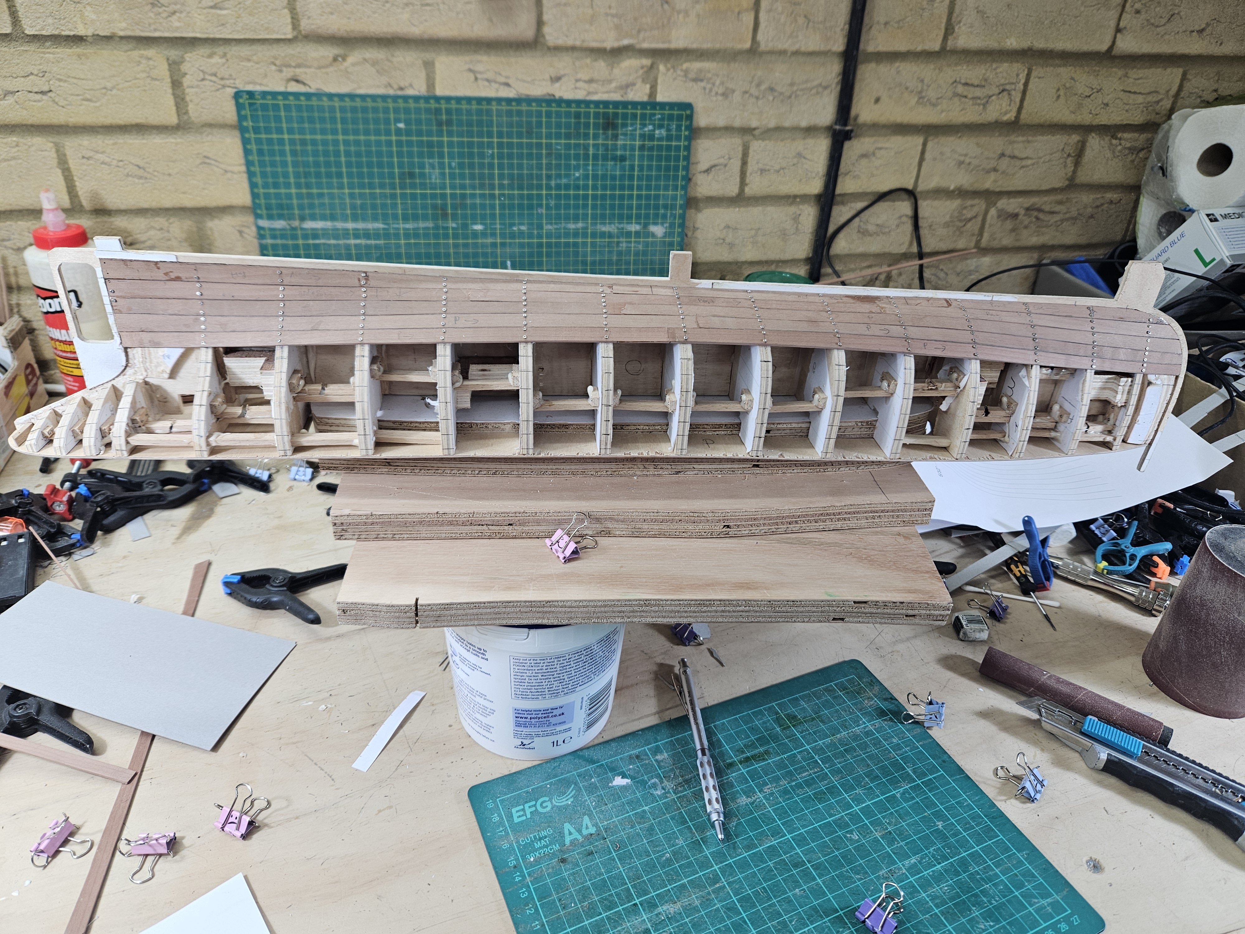
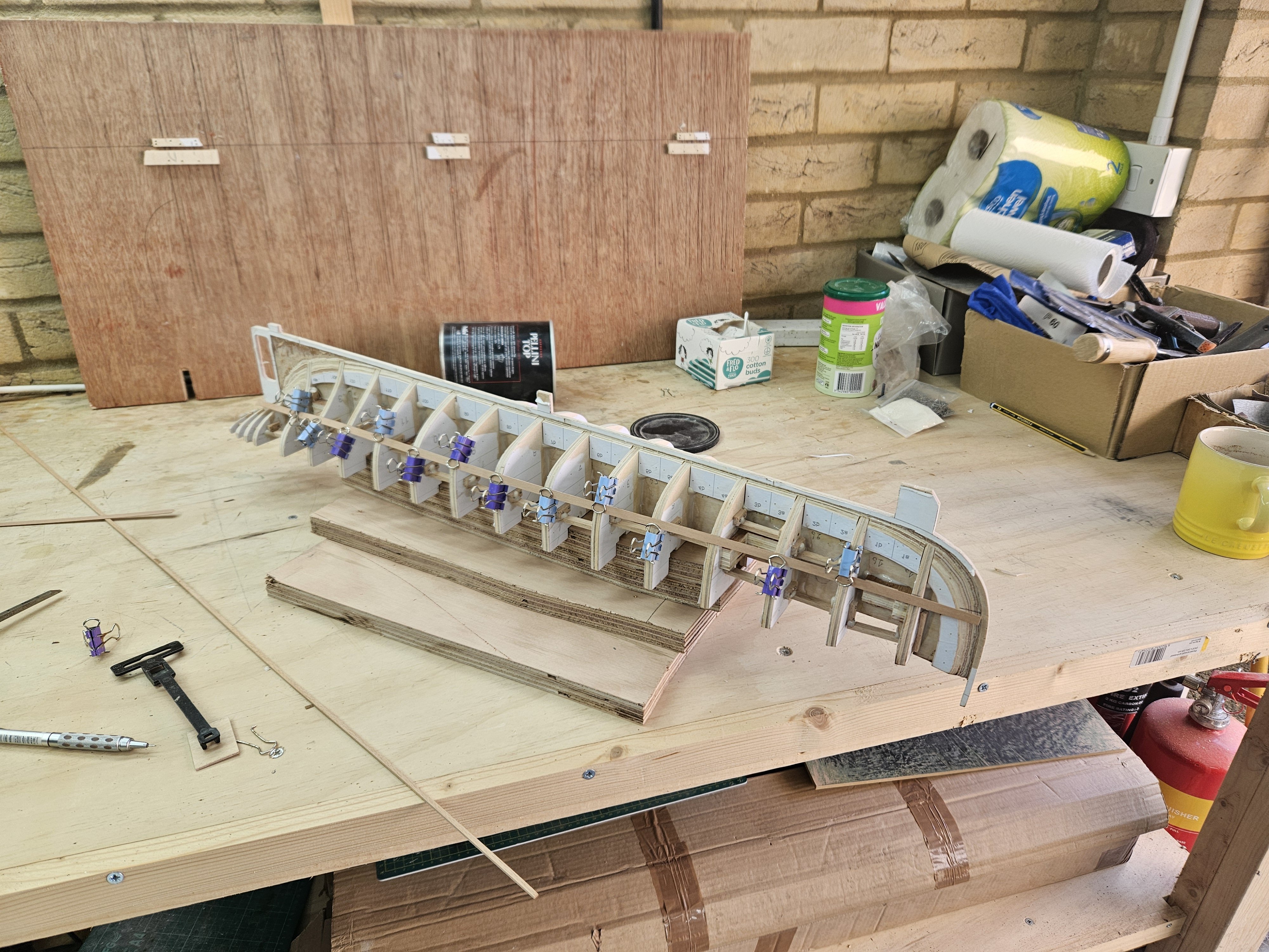
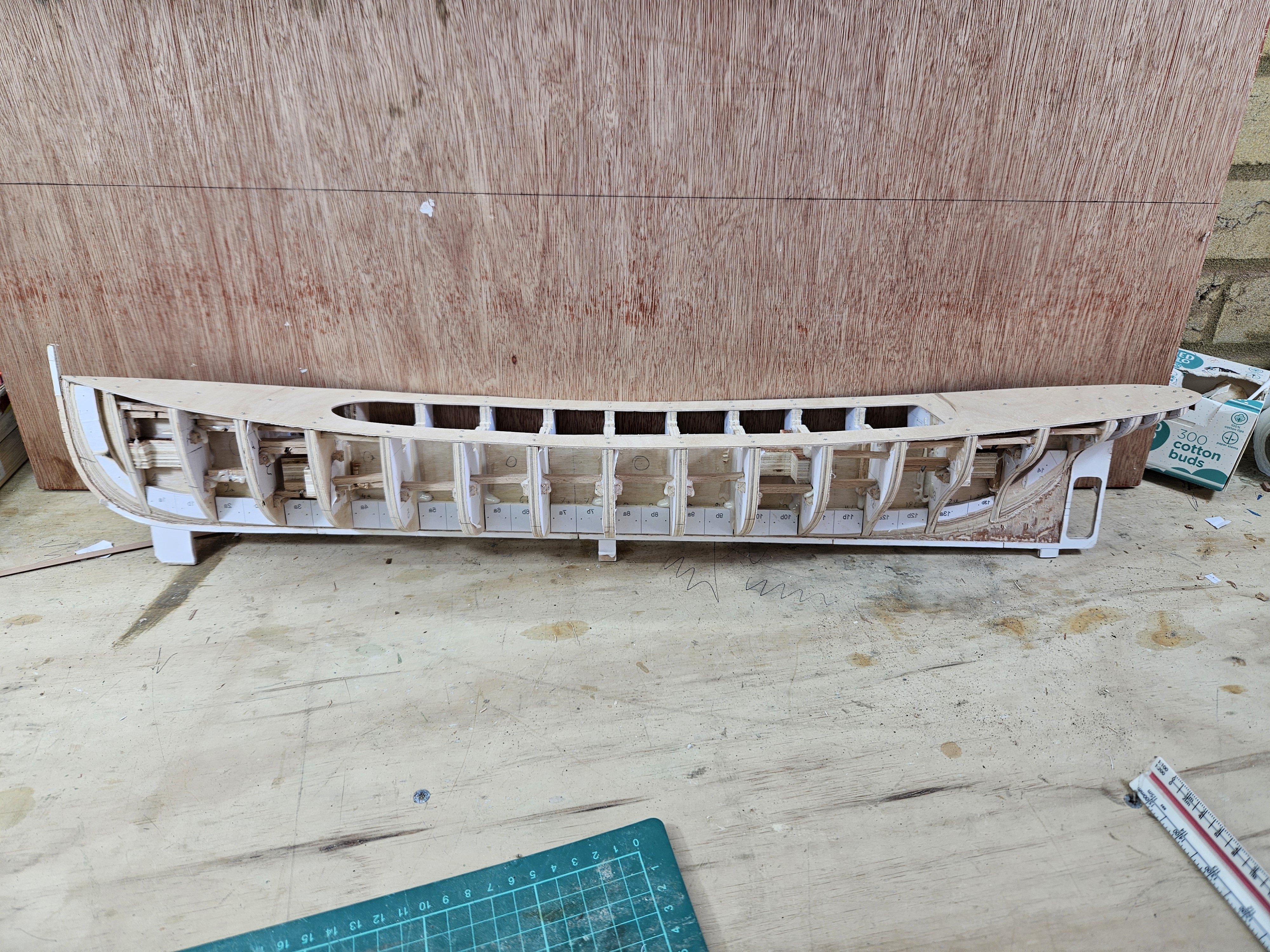
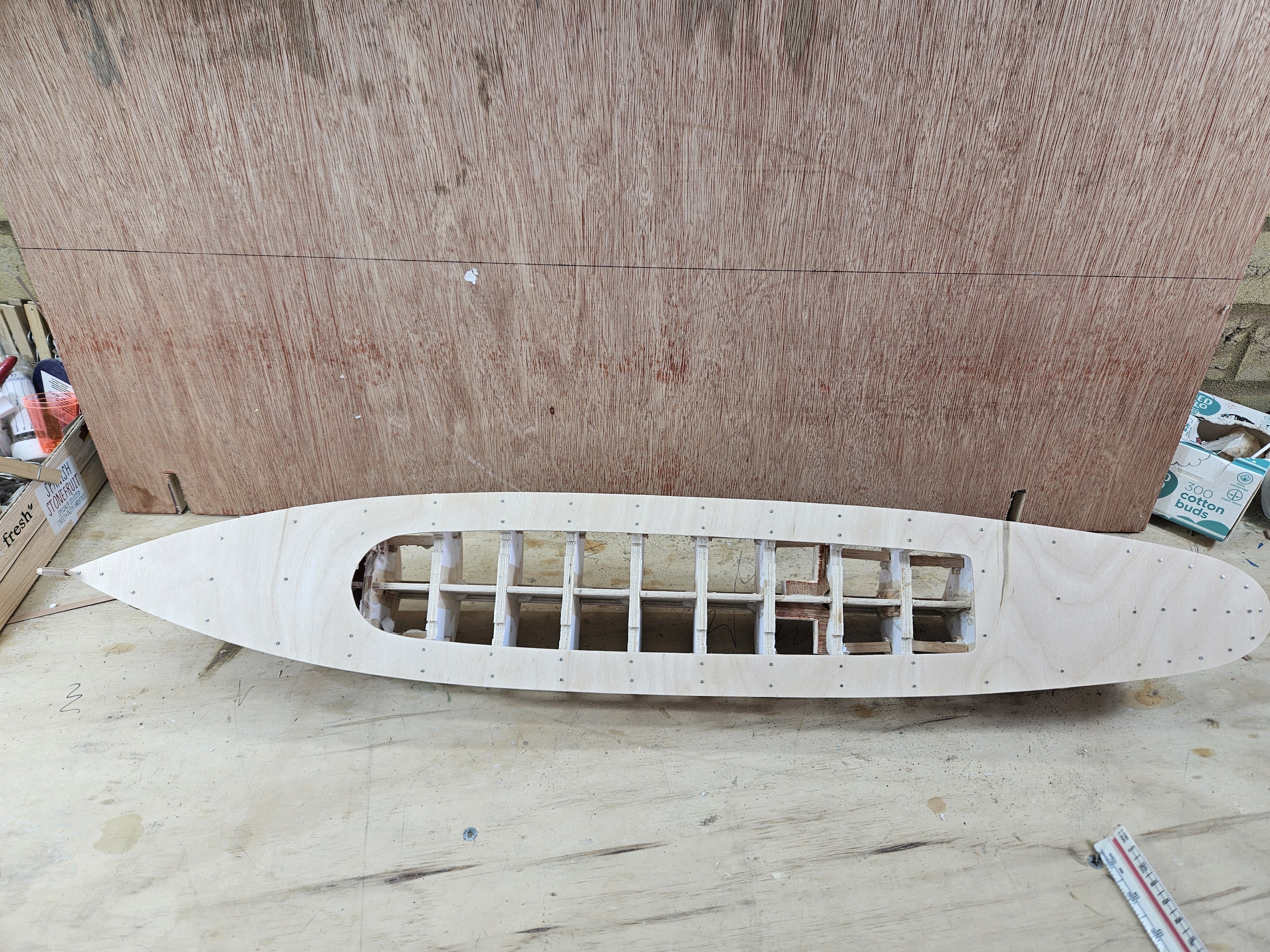
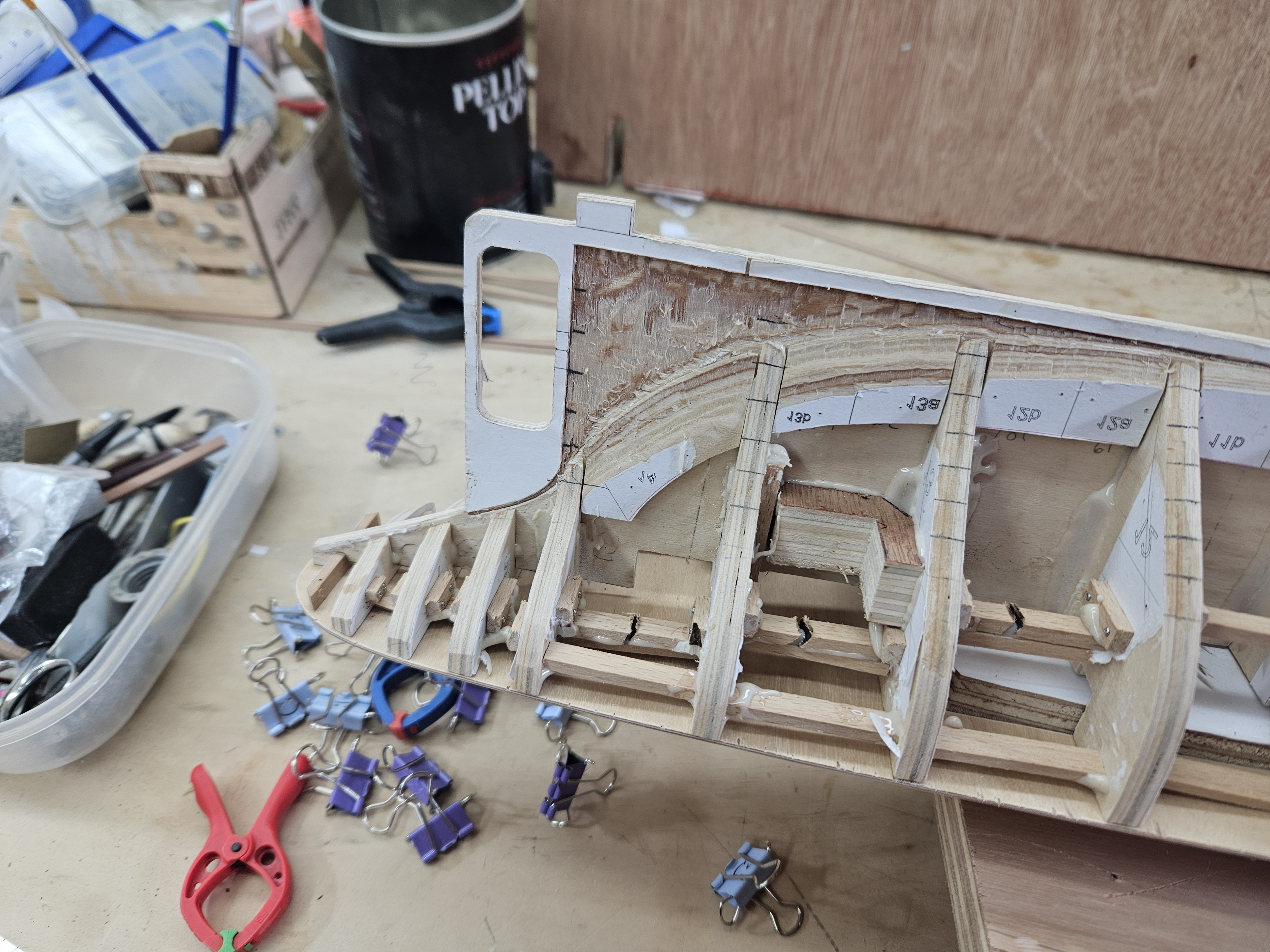
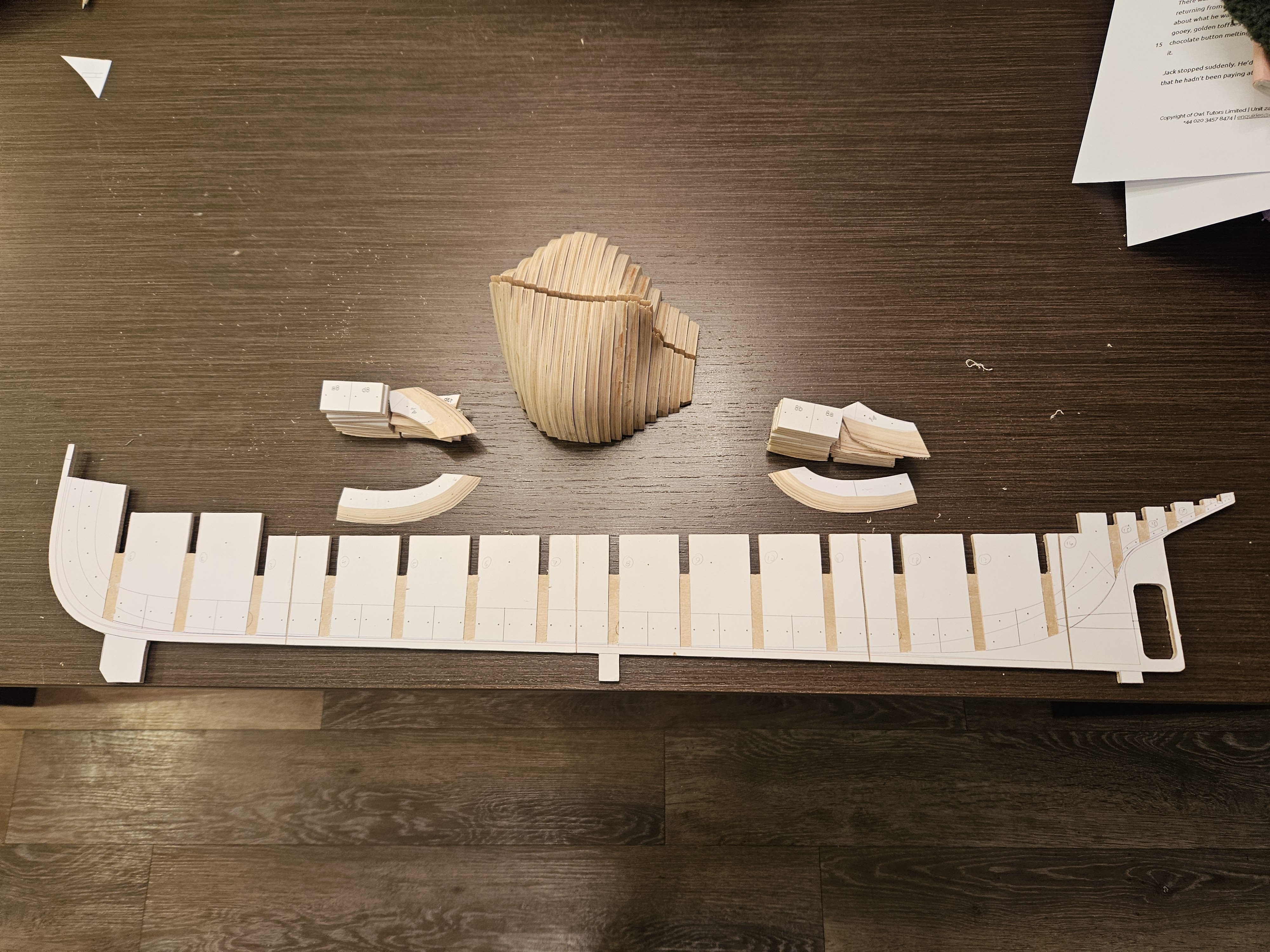
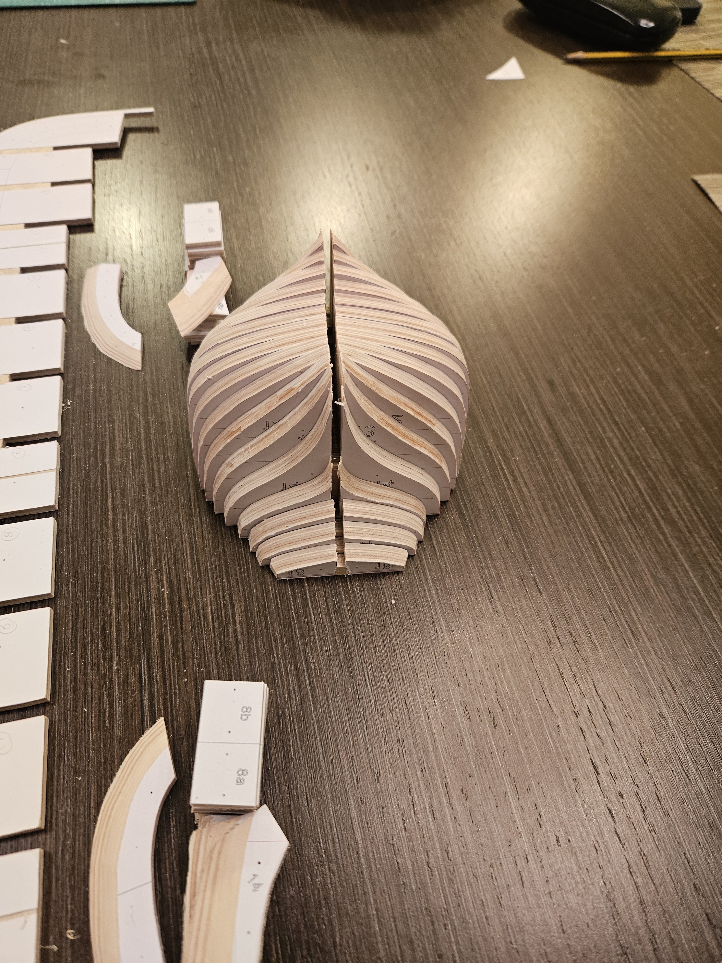
Dear all Thank you all for your comments and likes! I ve been working on the boat, walking a thin line between the Admiral's wrath and getting a few things actually done, so time for another update. Rob Ross used to say that there are no mistakes, only happy accidents. There sure have been many happy accidents so far with this boat! Usually my CAD drafts are pretty accurate but as I move on, I am scratching my head as 1+1 does not always make 2, I cannot figure out what I was actually drafting. But so far I managed to more or less fix things. So planking is finished! You will see that the sheer strake, or rather half of it, is missing. The reason is that Hercules has a tall bulwark and it would be difficult to securely fix it in place so I thought it made sense to merge the sheer strake with the bulwark. Now Hercules is 150 feet long and made of steel so the planks are completely unrealistic but they do make a nice hull! The card templates (there were even more than these) show how much work actually planking involves with spilling and everything - still I had only 2 half planks that I had to re do as they came out very wrong. One of the many happy accidents is in the following photos. I did not really want to buy new wood so I had just enough pear for the planking. I managed to snap the very last length I had left, with just a half plank left to do! I managed to fix this by making it in two parts, narrow escape! Then lots of Osmo filler and lots of sanding. Of course I did not read the instructions that state to thin the filler with 15% water and I struggled wasting a lot of the expensive filler. Prior to that, all the hundreds of screws were replaced by tree nails. Much more filling and sanding will be needed but a big chunk of the hull preparation has been done. Then I made the bulwarks but only after I managed to snap the little stem extension not once but twice. I had a sheet of maple and three sheets of mahogany left so I used maple - what a nice wood it is! It will all be primed and painted black. But something felt wrong. I went back to my CAD drafts and the plans and indeed, the bulwark/planks were a couple of centimeters short. The happy accidents are piling up! Now, Hercules has this little feature at the stern where there is a small flat vertical segment, this has to be made by laminating thin strips which gives the opportunity to correct the mistake above. So I used some thin beech strips I had. I dislike beech due to its huge movement in service but it is so nice to bend, just with water it can be tied in a knot. I just used PVA to laminate the strips, if I had used epoxy it would have been very messy. Then rough cut to shape and screwed in place. I know it looks rough, I had trouble with the stern drafting in CAD and did not really spend time on it, I hope I ll fix it with a bit of filler, bit of sanding, paint on top. I am enjoying this boat, it is very different from anything I have built so fat. On another note, the postman dropped a cardboard tube with some plans which are currently being processed. There will be a new log starting, this time for a far more complex boat that will take a long time to build, a boat that from the first time I saw it I new I just have to make! Take care all Vaddoc


-
Gold solder for brass
vaddoc replied to Richard Braithwaite's topic in Metal Work, Soldering and Metal Fittings
How about phosphorus-copper paste solder https://www.ebay.co.uk/itm/163407180441 This is what I use, gives a light brass colour and paste is easier to use than bits of solder Vaddoc -
Thanks Mark and Jim and all that hit the like button. A bit too early for an update but It's exciting seeing the shape of the hull slowly emerging. Boats are such beautiful things! Vaddoc


-
There is a paint section/thread with good info, have a look. Paint will bleed under ordinary masking tape or electrician tape, you need frog/Tamiya or similar. This tape must be carefully stored so edges do not get destroyed. For wood there is no adhesion issues but a primer will give a uniform colour on the surface. It is important to seal the wood though - many use Shellac and methylated spirits, I use decoart Americana water based sealer. Test on scrap wood, not the model! Vaddoc
-
This was very interesting Phill (and very well done!). I also had never heard of sacrificial sheathing before. Somehow though, I kind of think that, even though the expertise existed to properly spill and bend planks, it would be unlikely to spend time and effort in a military vessel, especially for a sacrificial layer that would not contribute to hull strength or water tightness. I think they just screwed the timber in, any way it seemed more time and material efficient, not far of what you ve done. Vaddoc
- 492 replies
-
- 3
-
-
- minesweeper
- Cape
- (and 1 more)
-
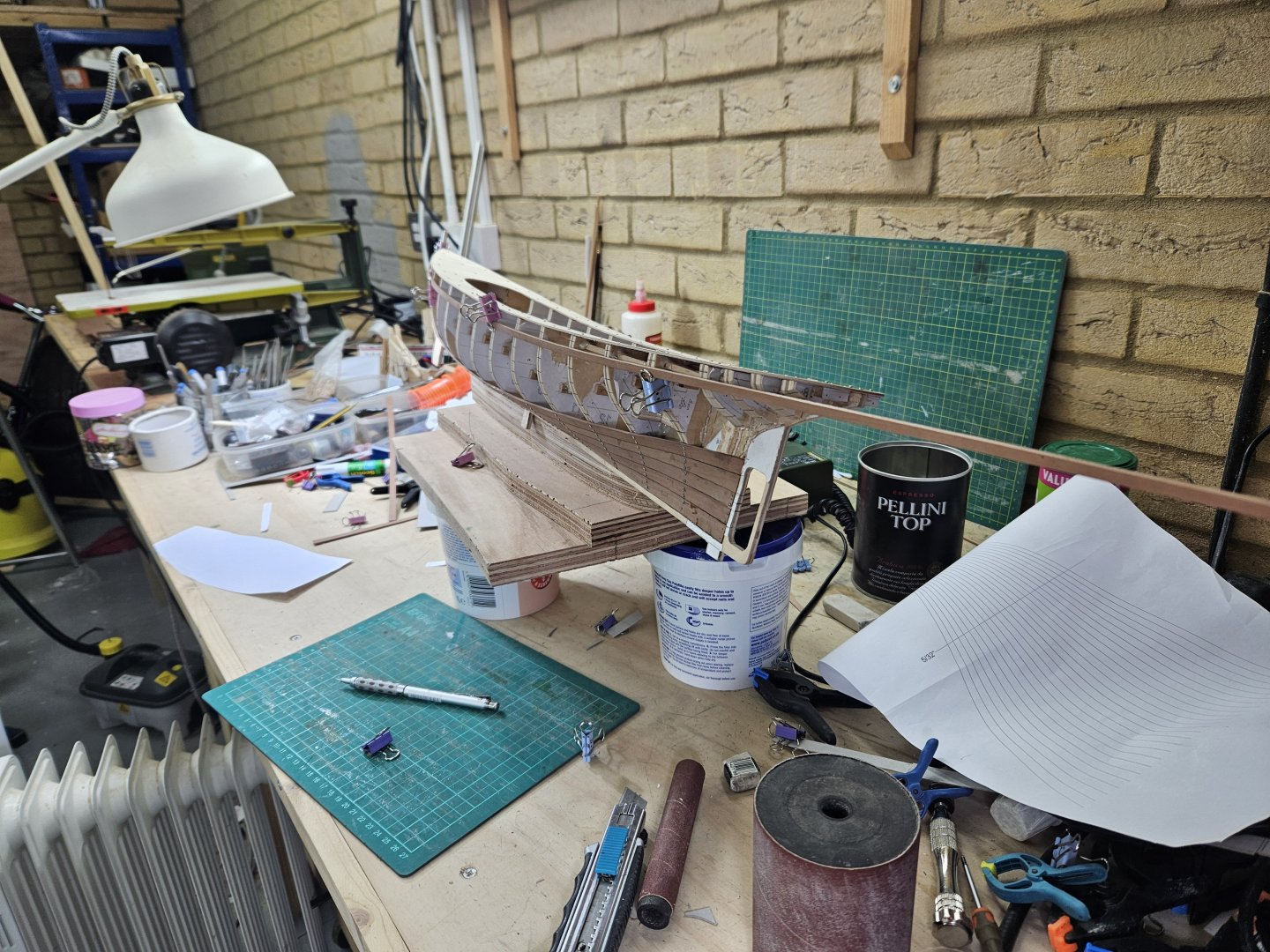
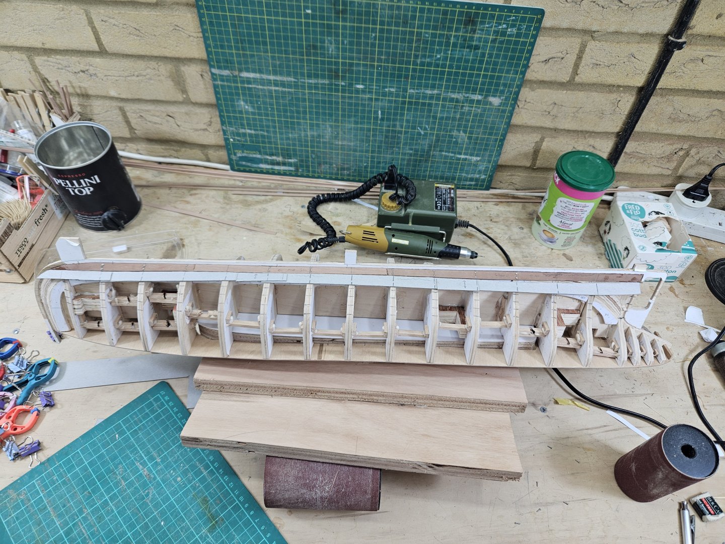
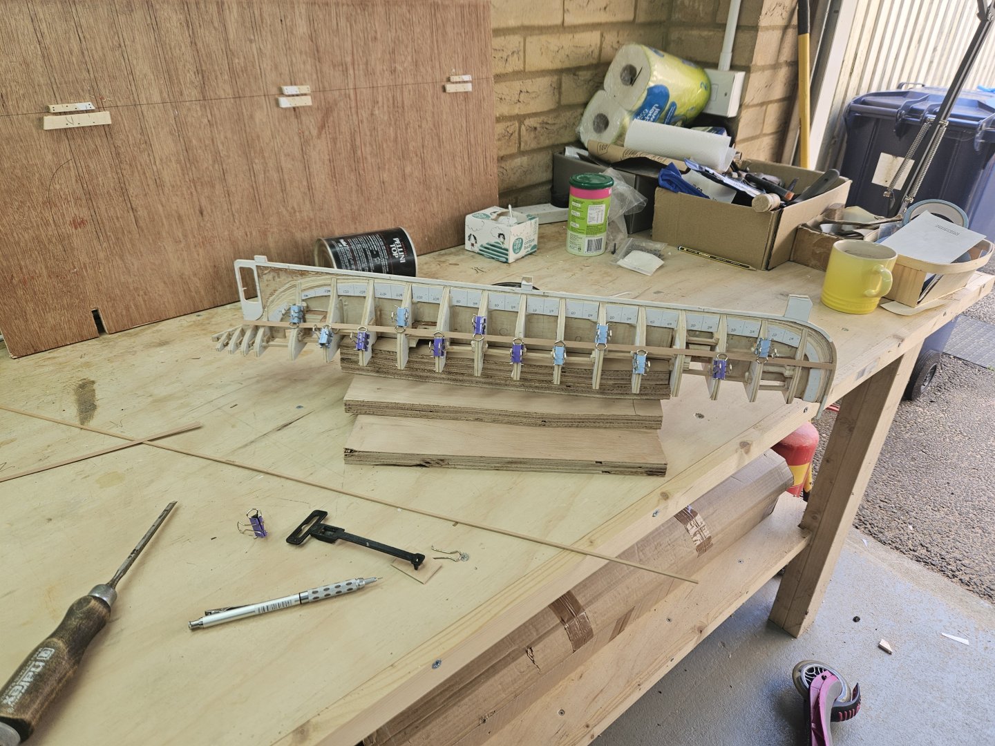
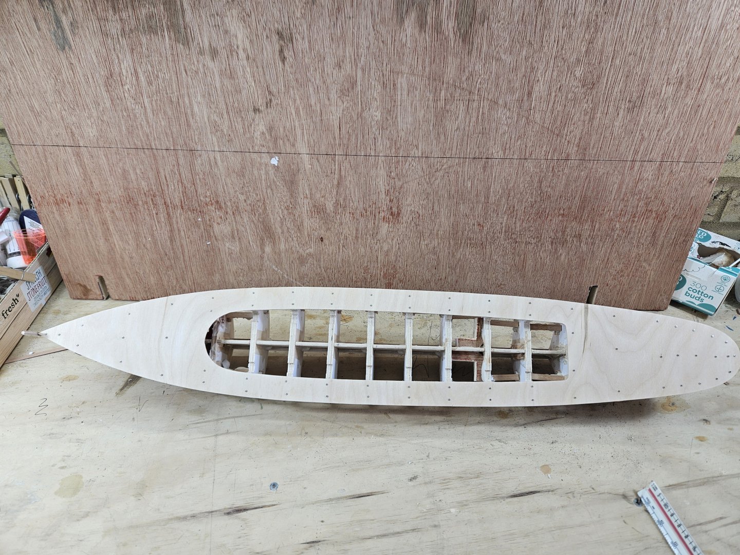
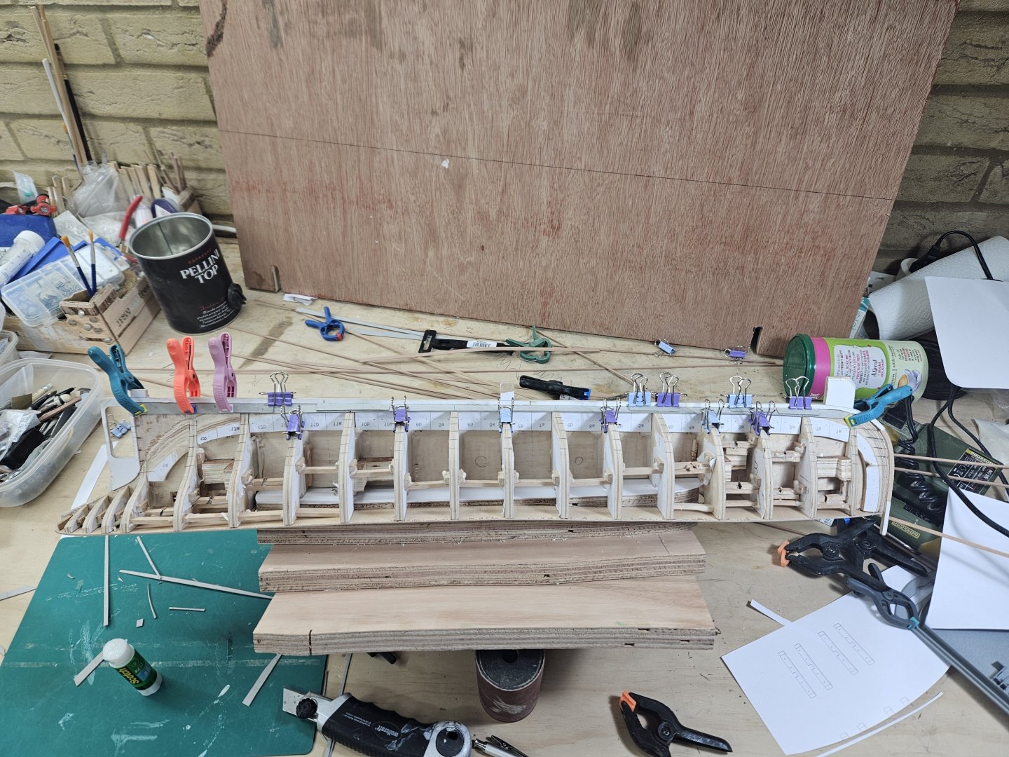
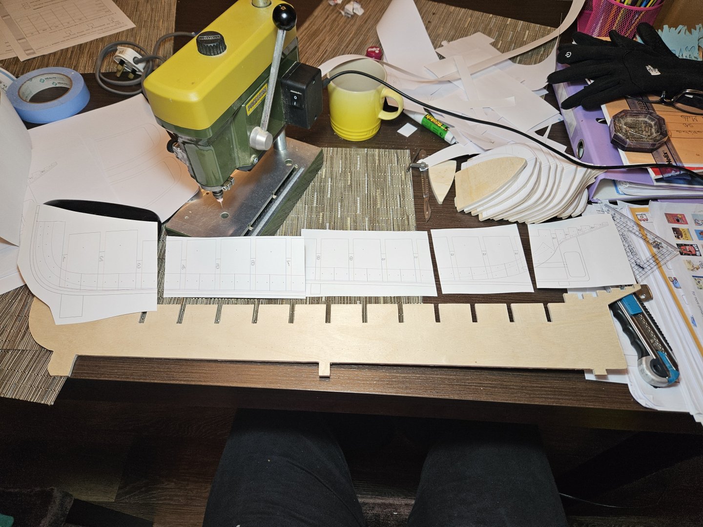
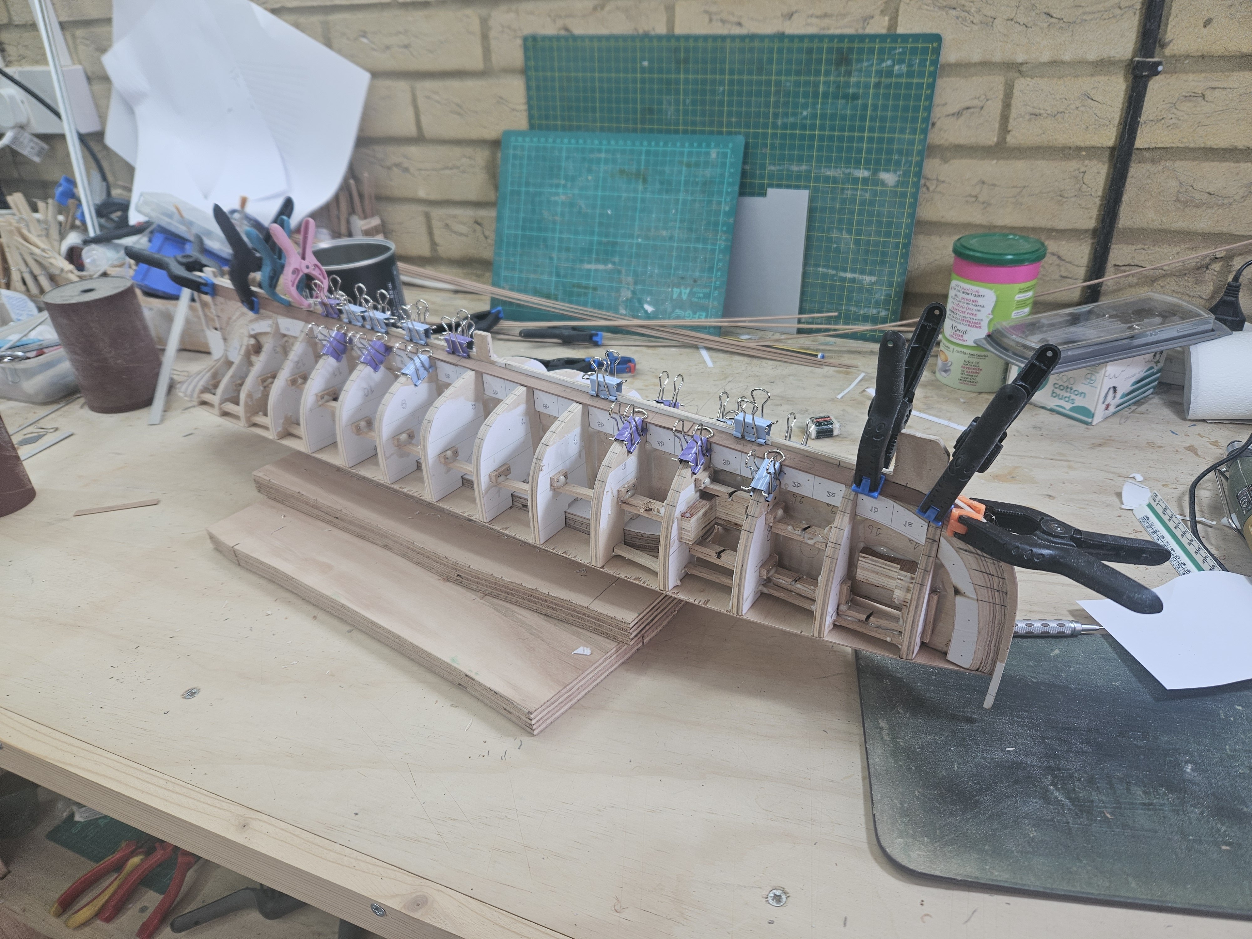
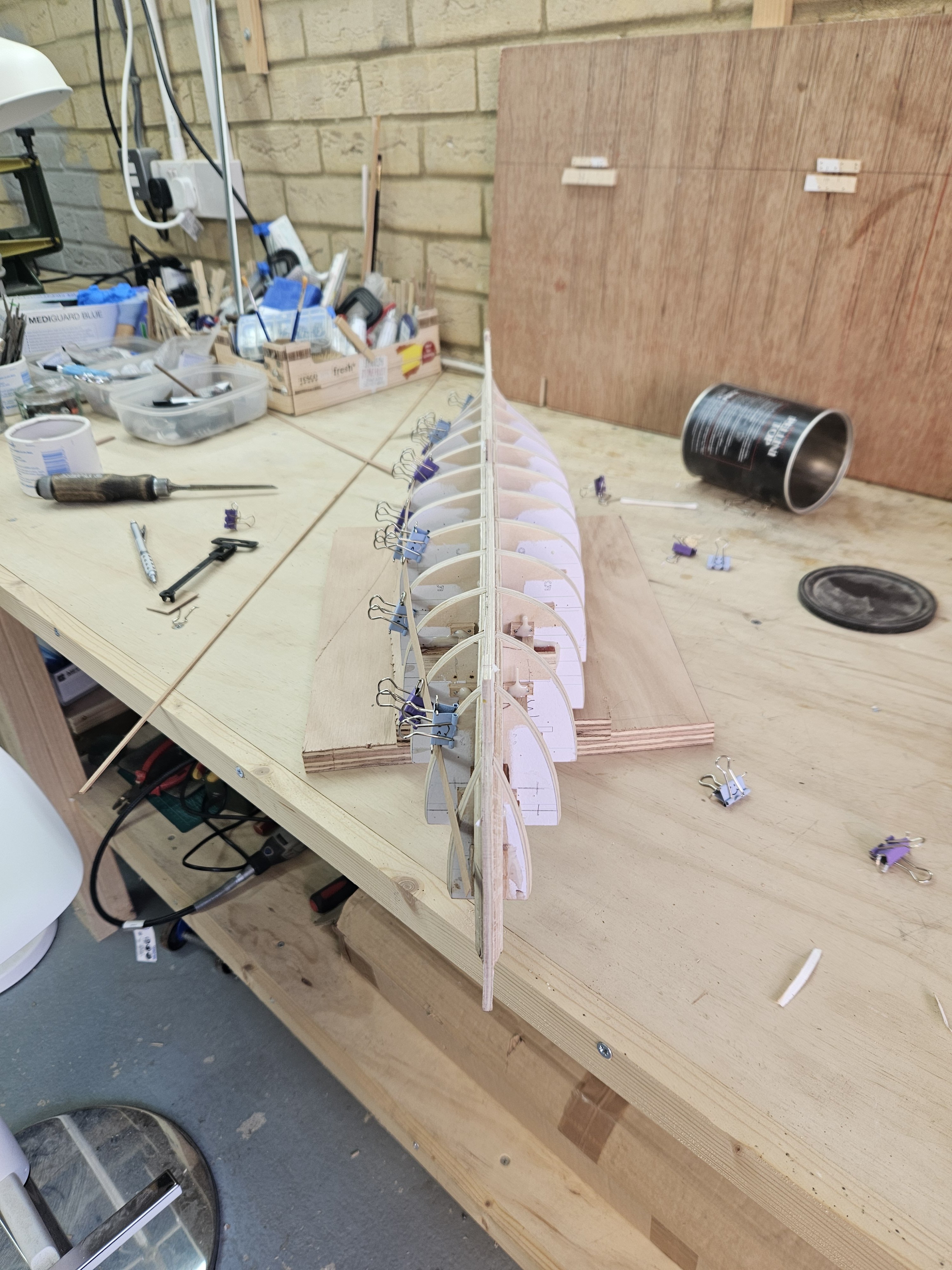
Time for a wee update! I did lots of work but have little to show, planking is a slow, labour intensive process. I need to cut the plank patterns for each side separately as the port and starboard planks are very close but not identical. I try to fit the edges reasonably close but I am not too fussed, with a bit of sanding and filler it will be fine. Also, I really should have hollowed the planks where they meet the frames at the turn of the bilge but it will be fine. The plank scarfing is a bit wonky but this will also be ok with some sanding. I realised that to progress further I had to mark all the remaining planks. One of the aft frames looked (and still looks) a bit wrong so I cut some of it off and overall I am not sure how the stern will end up, so some head scratching there is needed. Also, the sheer plank will continue as gunwales so this also needs some more thought. I am not sure I have enough pear to finish the planking, I ve managed so far not to waste any wood but today I made two wrong planks - this is a lot of waste! 5 planks are in and the run of all the remaining planks marked. Of course the width of the planks is all way off scale but Hercules had a metal hull and I just want to plank the hull - there is no reason though not to do it nicely! I think the planks so far run reasonably fair. The sheer also looks ok. Please do excuse the huge mess in the yard! Now, I may have a £200 gift card to spend and some money to add to it - I may get a milling machine! (Proxxon MF-70?) Best wishes to all Vaddoc


-
I don't think you should worry about the paint filling the gaps Phil, if anything it should make these stand out more.
- 492 replies
-
- 1
-
-
- minesweeper
- Cape
- (and 1 more)
-
Best White Wood Glue For Ship Building
vaddoc replied to OldeManToad's topic in Modeling tools and Workshop Equipment
@OldeManToadMy impression and experience: PVA glue is white, dries clear and has some forgiving opening time before it sets. Aliphatic glue is yellow wood glue, does not dry clear and sets very quickly - very little opening time if any. I use both but mainly the white PVA. Wood glues can be waterproof or not. @Dr PR This really looks interesting Phil. Is Duco cement gap filling to any degree or does it need good surface contact like PVA? -
Thank you Mark. Well, I ve used epoxy for these joins, they are rock solid now!
-
Welcome GumDrop!
-
Very enjoyable journey Phil, just caught up with your build. 3/4 inch planks are very thin - what purpose did they serve? Vaddoc
- 492 replies
-
- 2
-
-
- minesweeper
- Cape
- (and 1 more)
-
Tally Ho by AntonyUK
vaddoc replied to AntonyUK's topic in - Build logs for subjects built 1901 - Present Day
Looks a fine model Anthony and your CAD plans look very nice as well. Tally Ho is a good model to build with such a video library on You tube. A fully framed model may be somewhere in my future as well. Very interesting building method though, foam and fibre glass instead of planking. I presume it will be a static model, not RC. The only advice I could give you is that epoxy is very messy, chronic exposure leads to development of sensitivity and most importantly, that uncured epoxy cleans immediately with vinegar (epoxy is very alkaline and dissolves with acid). I always have a bottle in the shipyard as epoxy is a messy business. Could I ask, what was in the plans that you received from the Albert Strange Trust? Best wishes Vaddoc- 34 replies
-
- 1
-
-
- mixed materials construction
- Albert strange design
- (and 1 more)
-
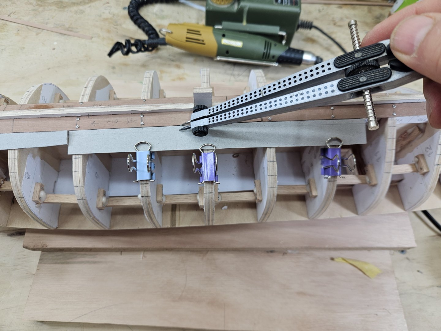
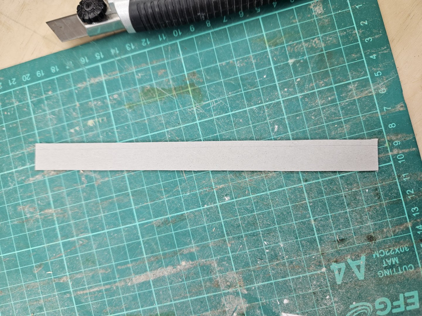
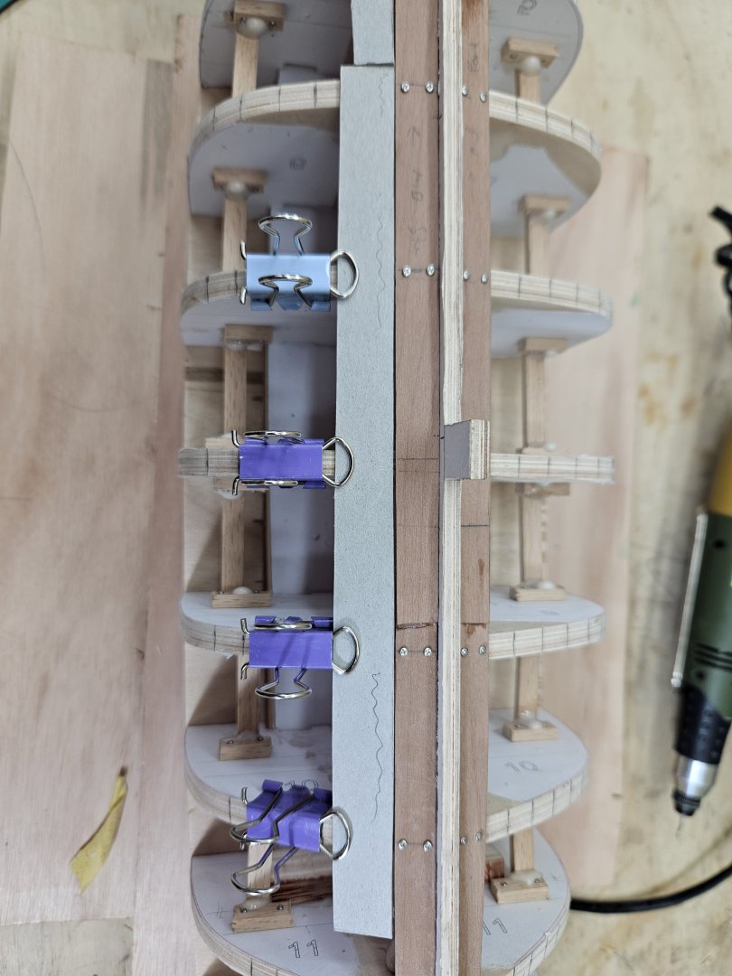
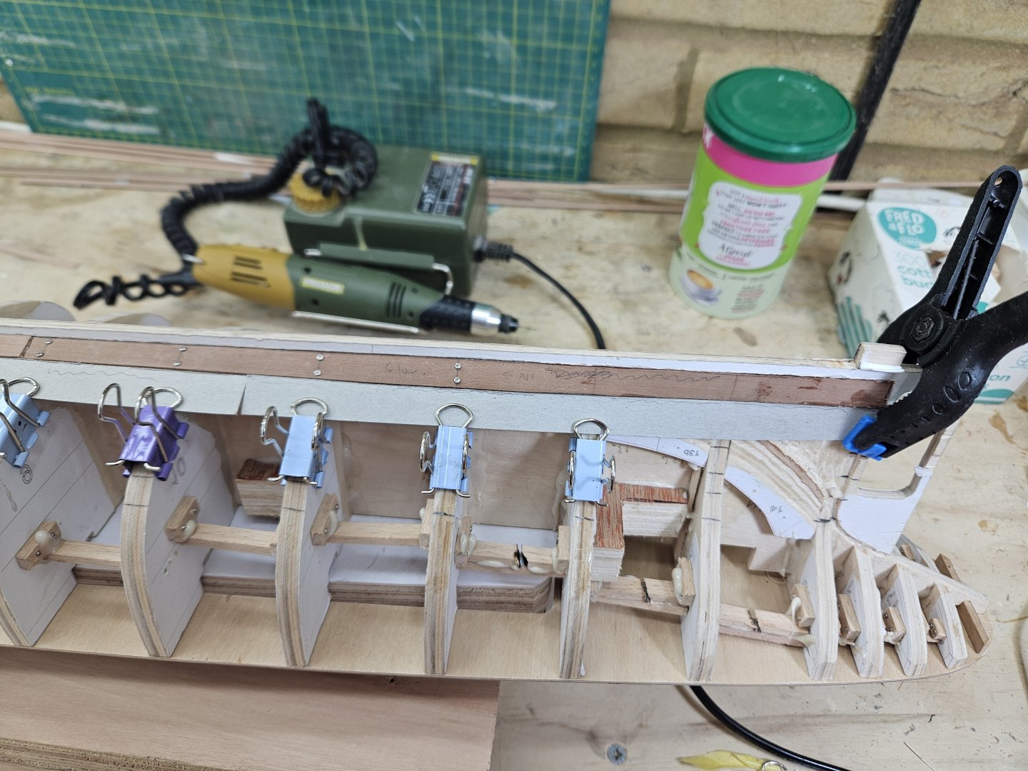
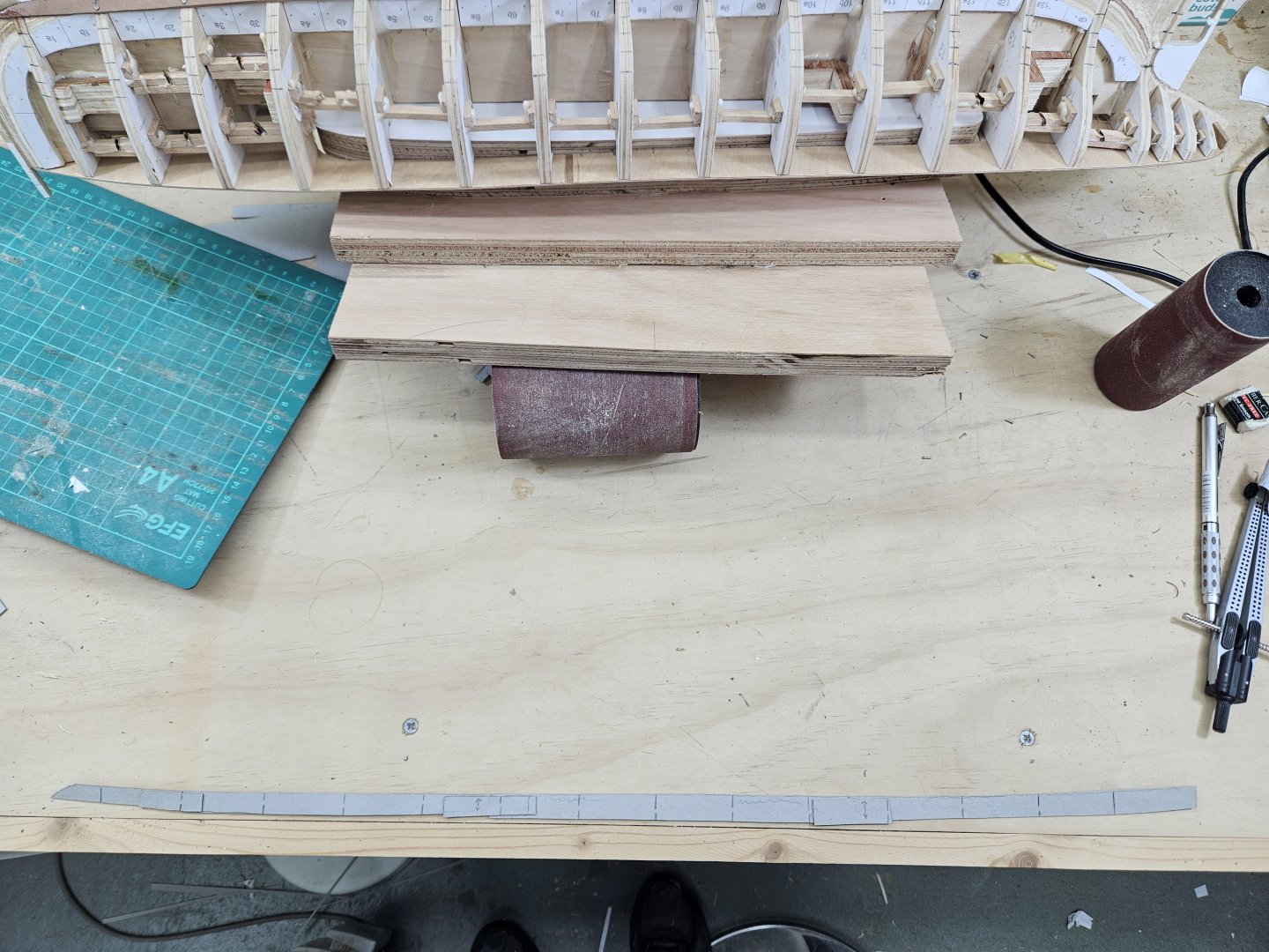
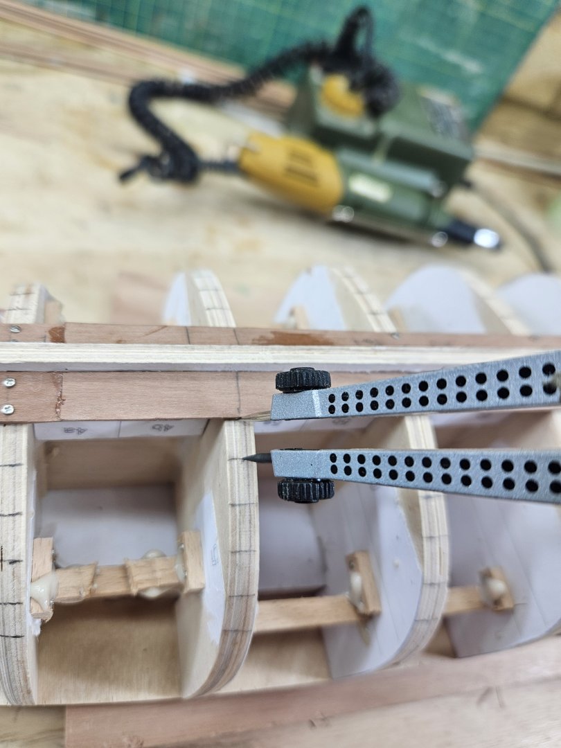
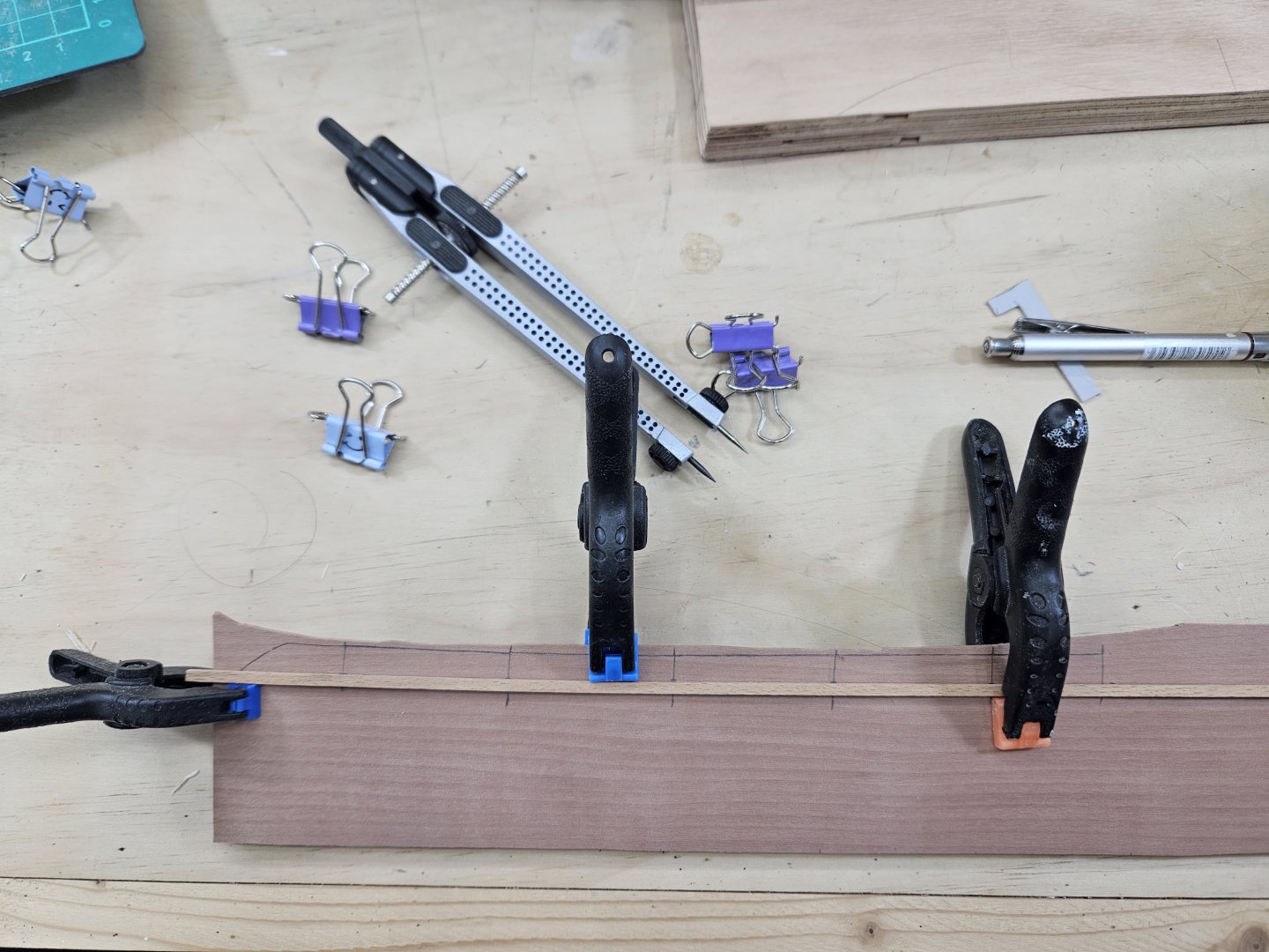
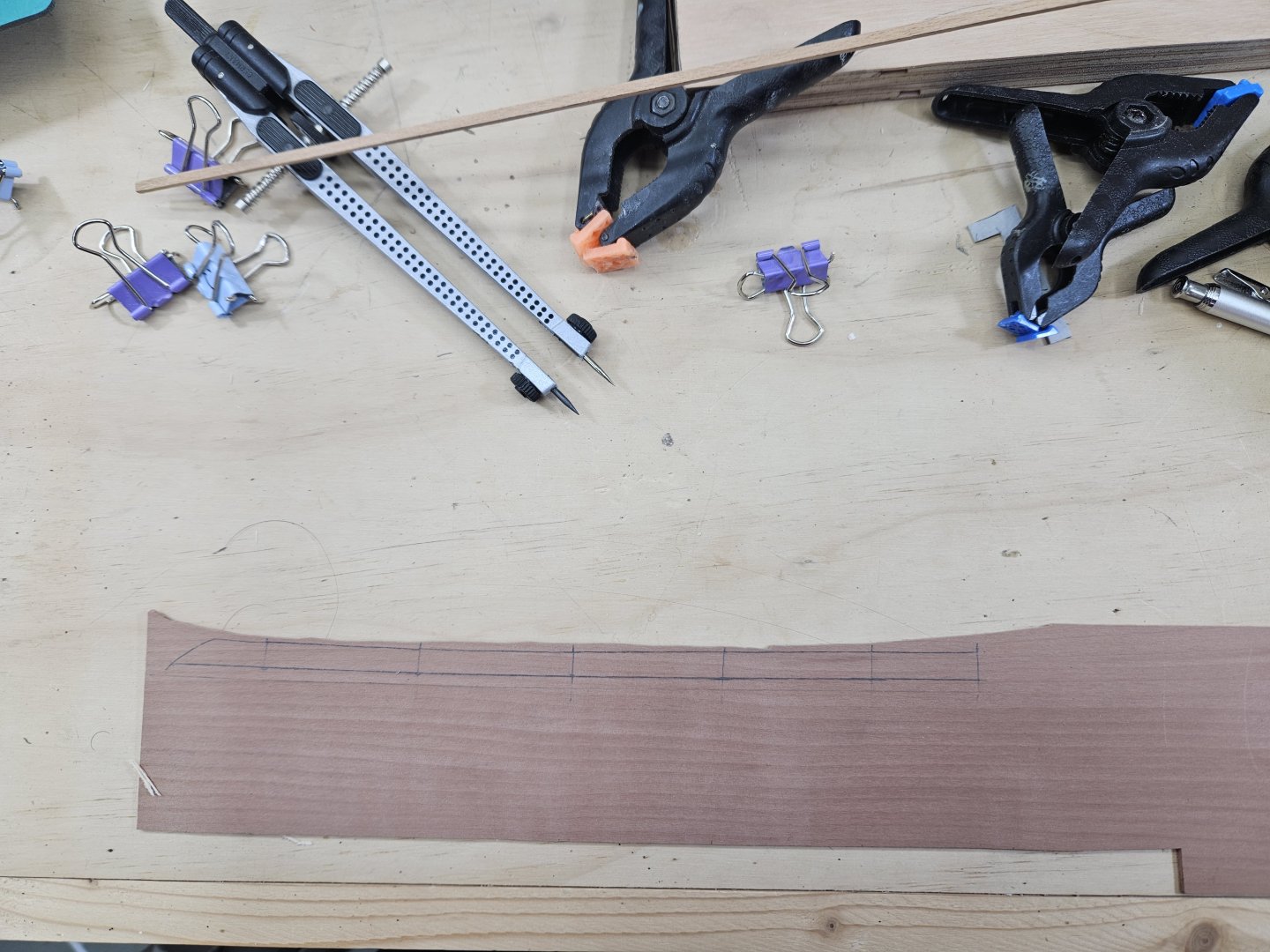
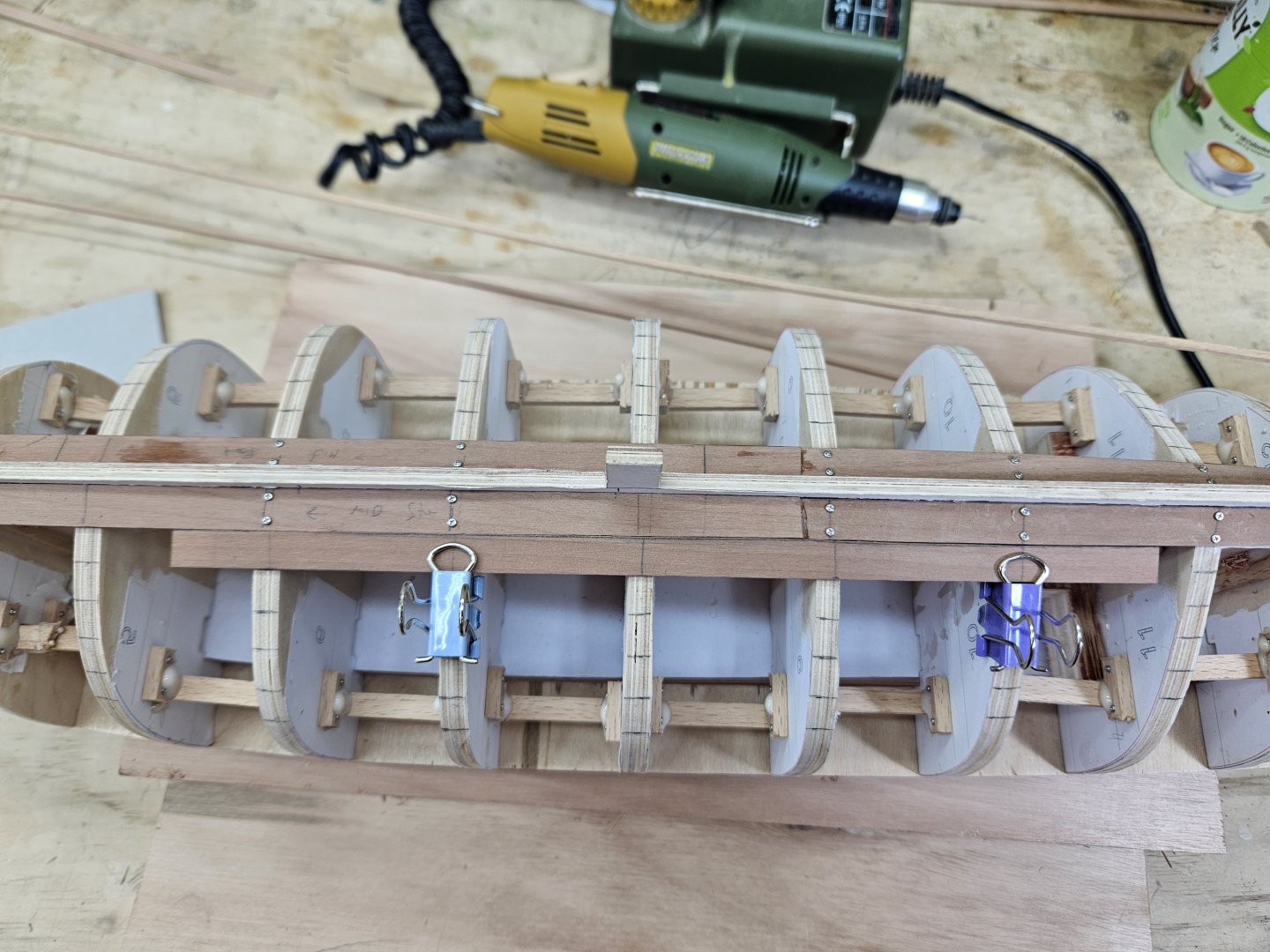
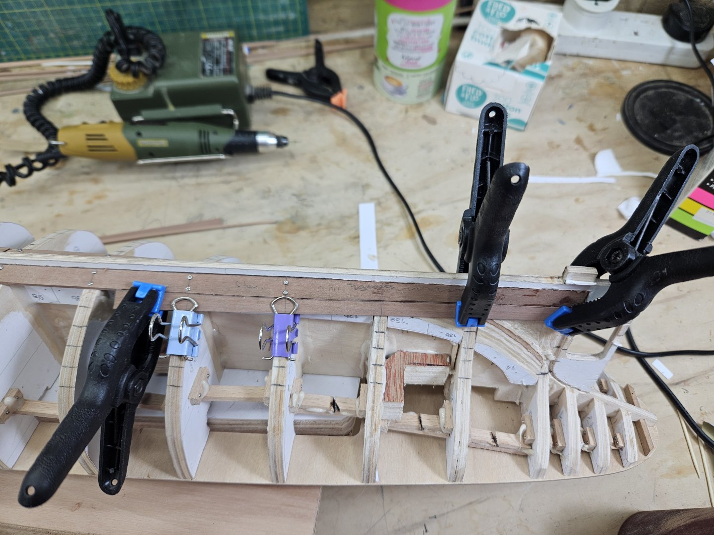
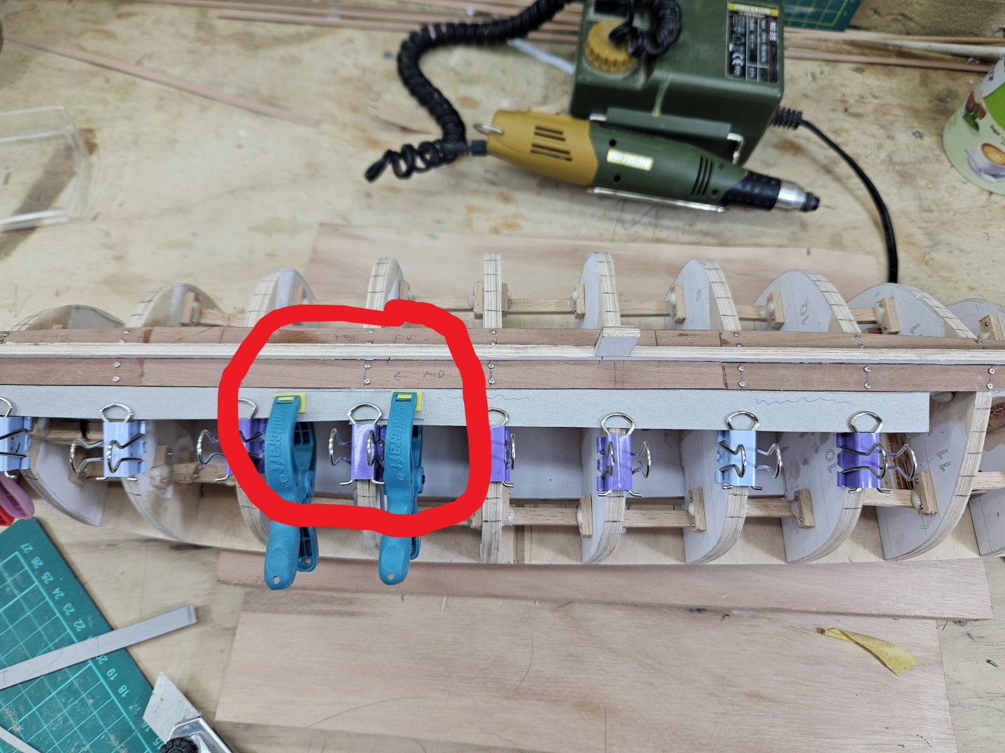
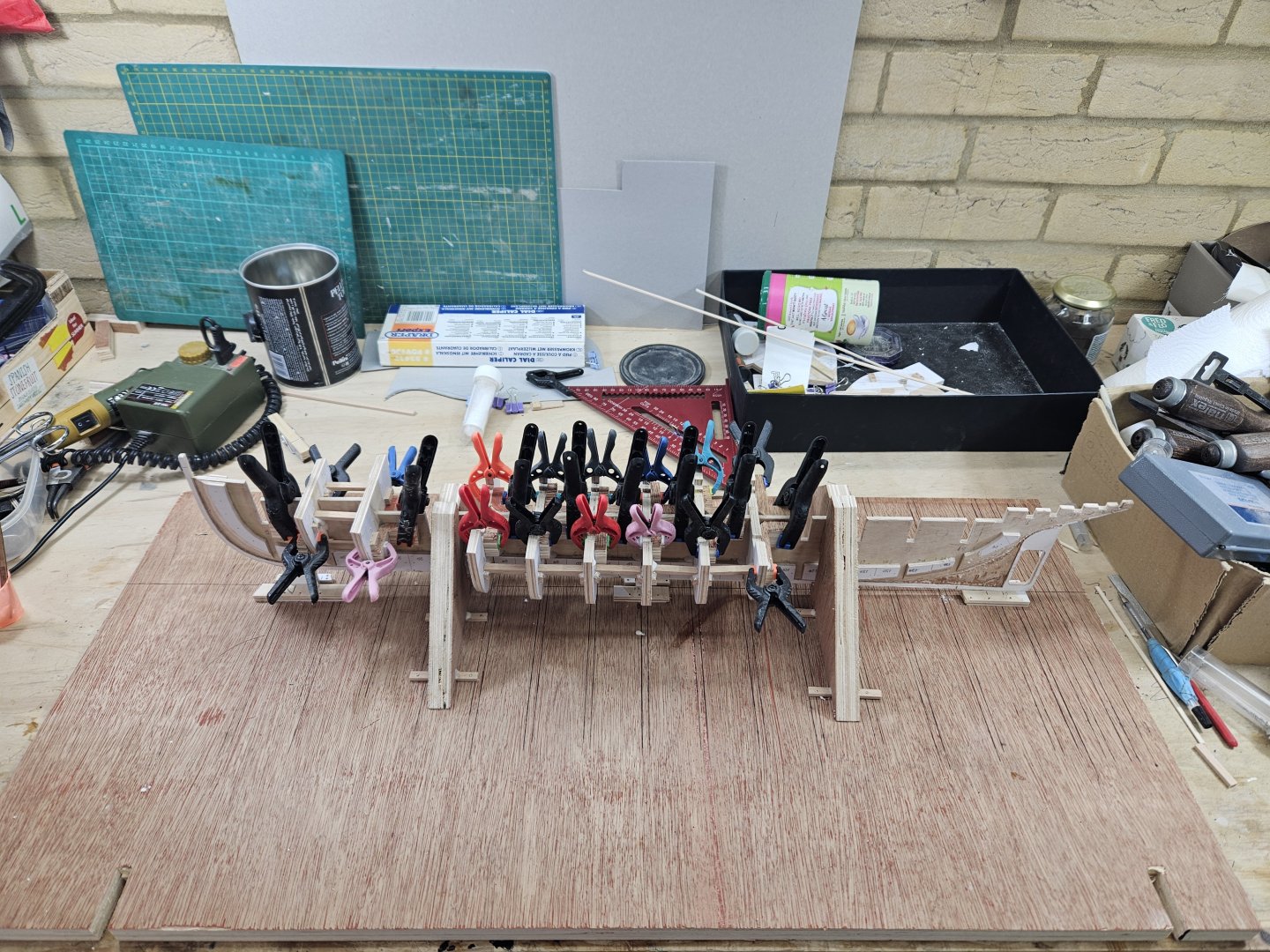
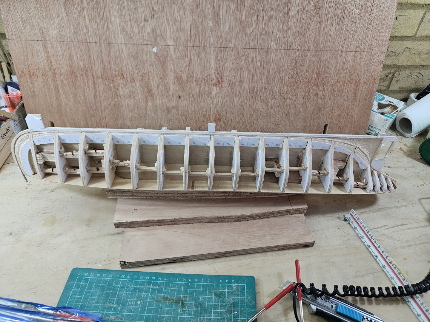
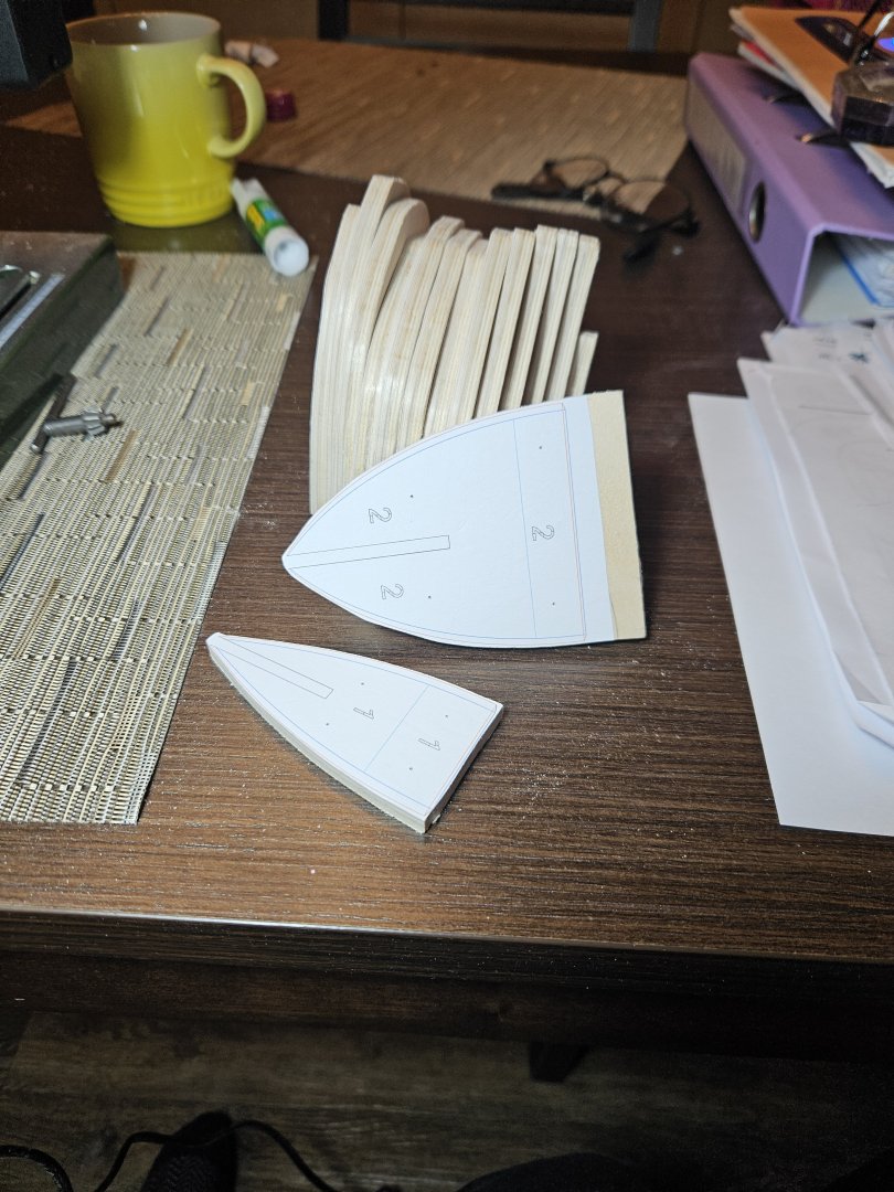
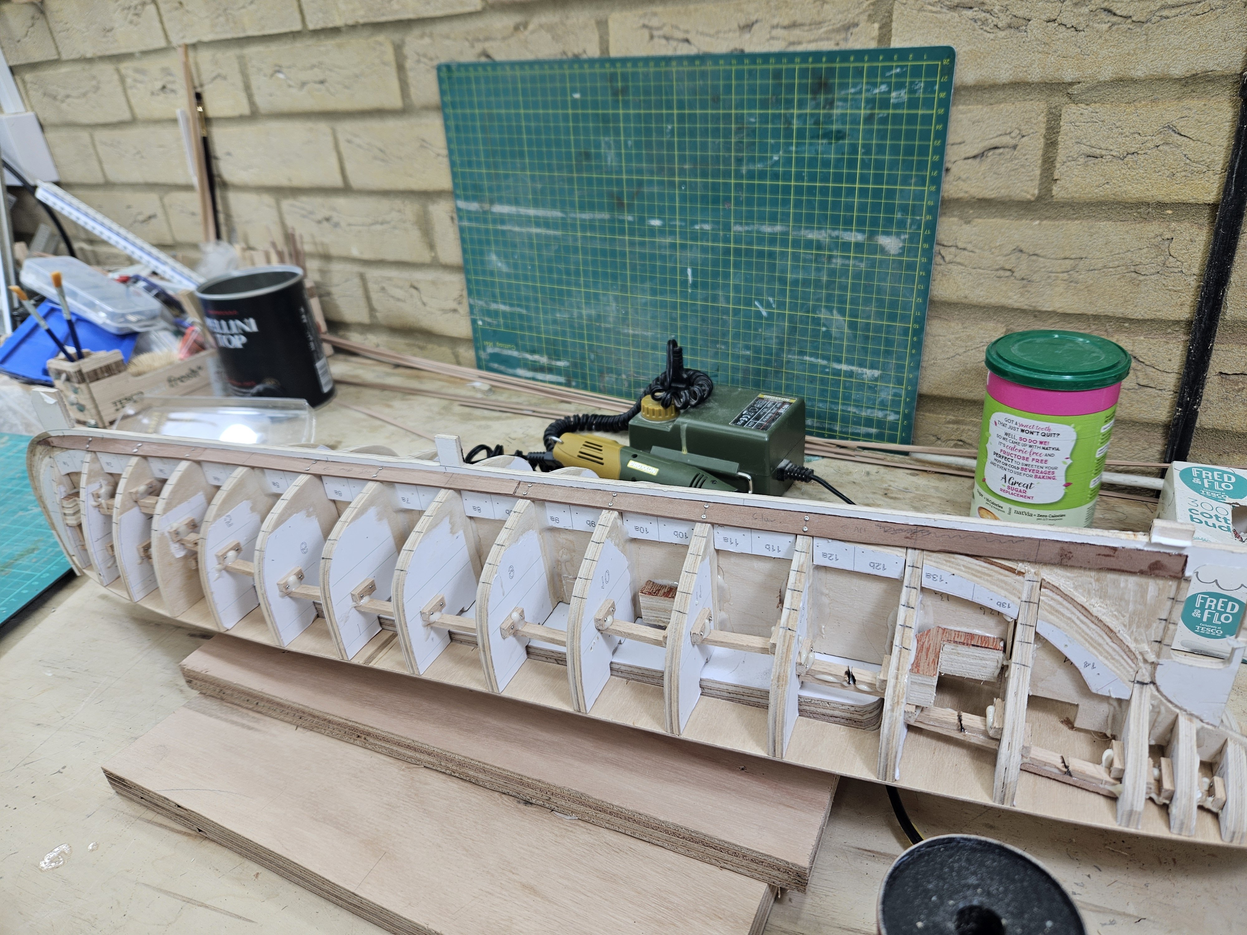
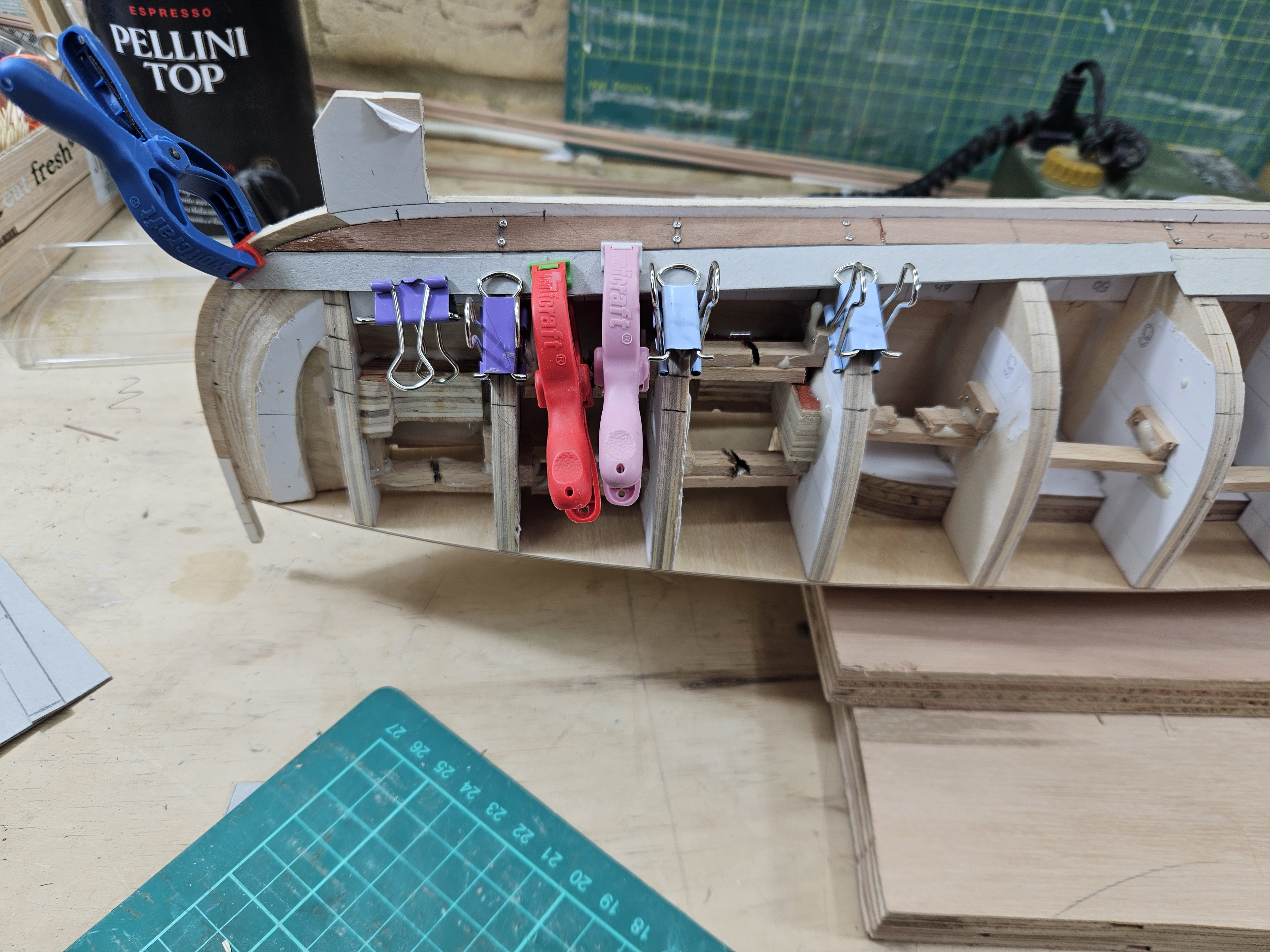
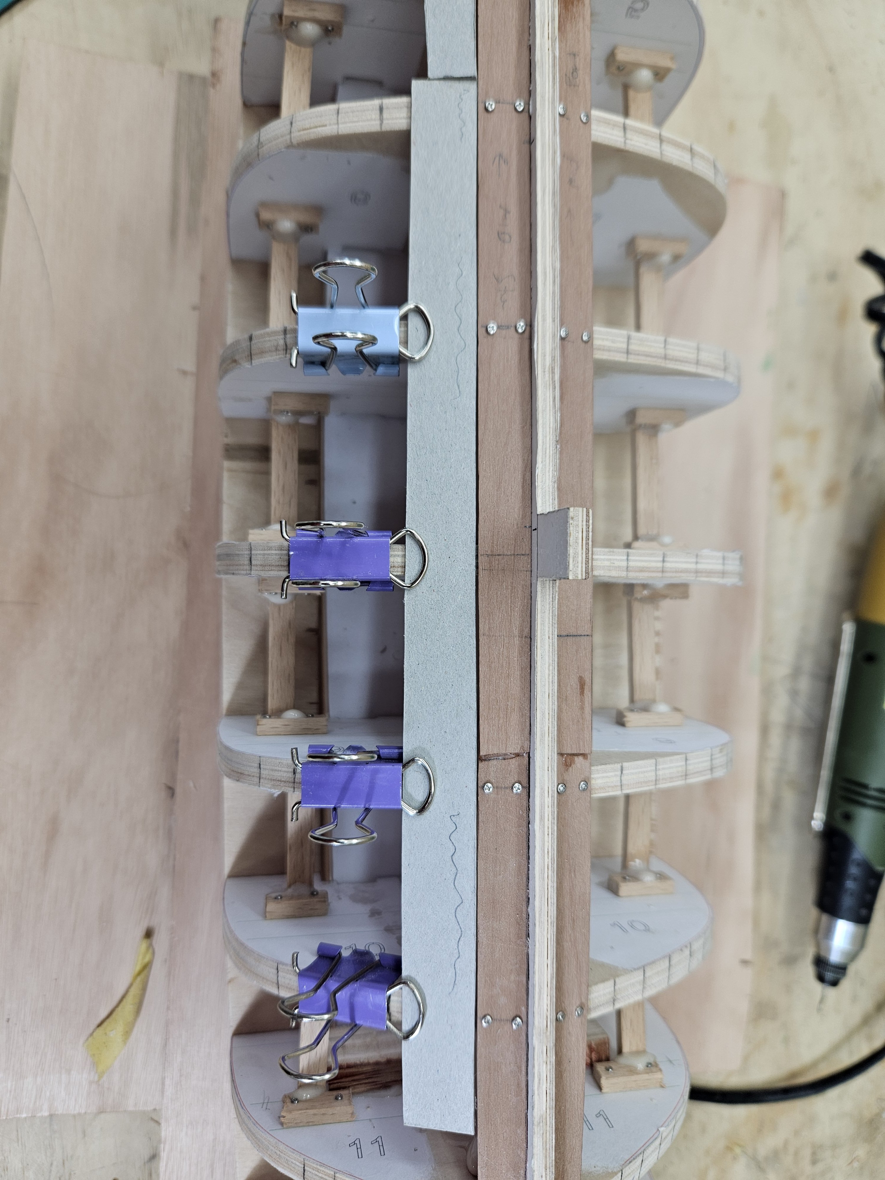
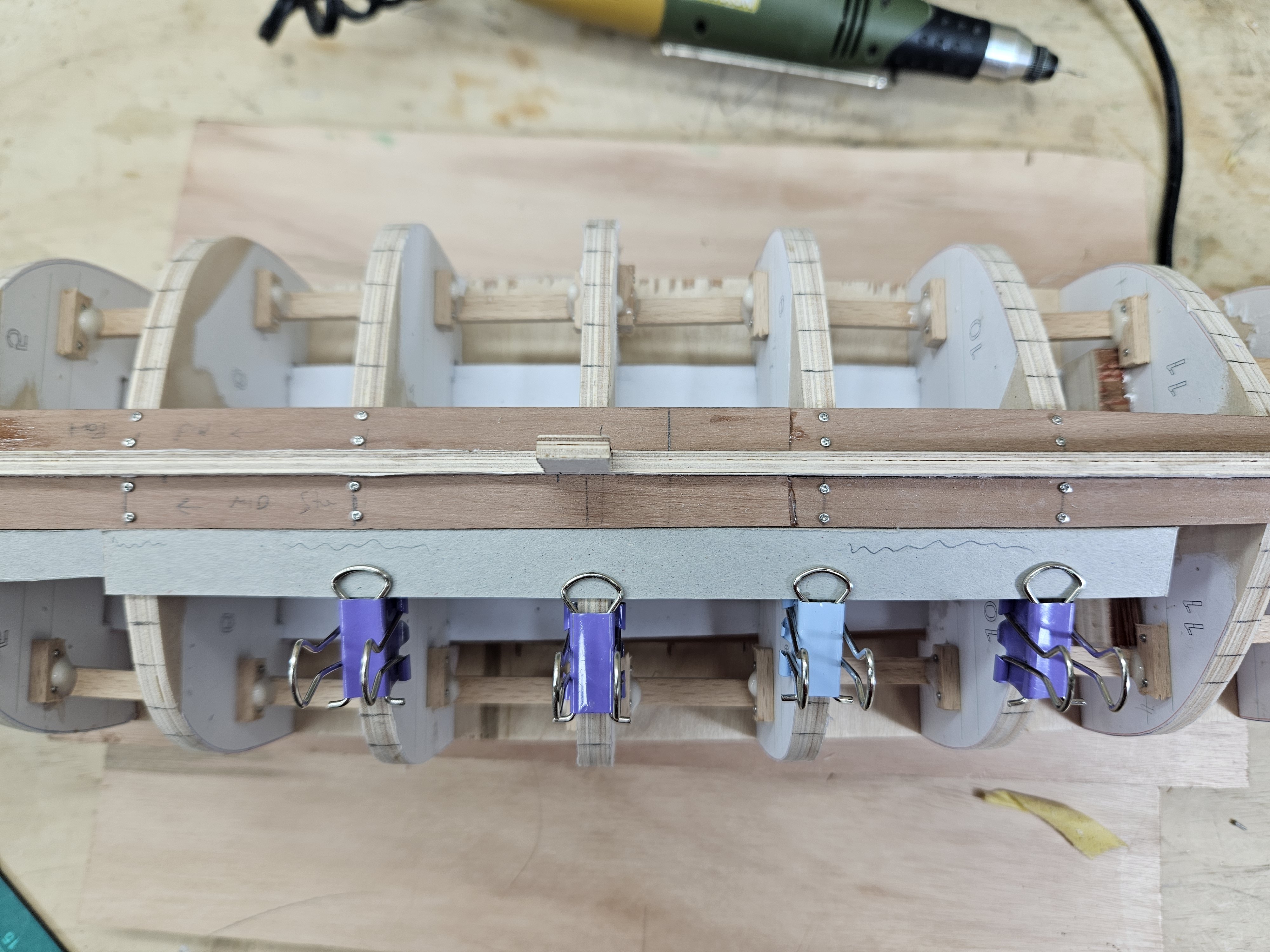
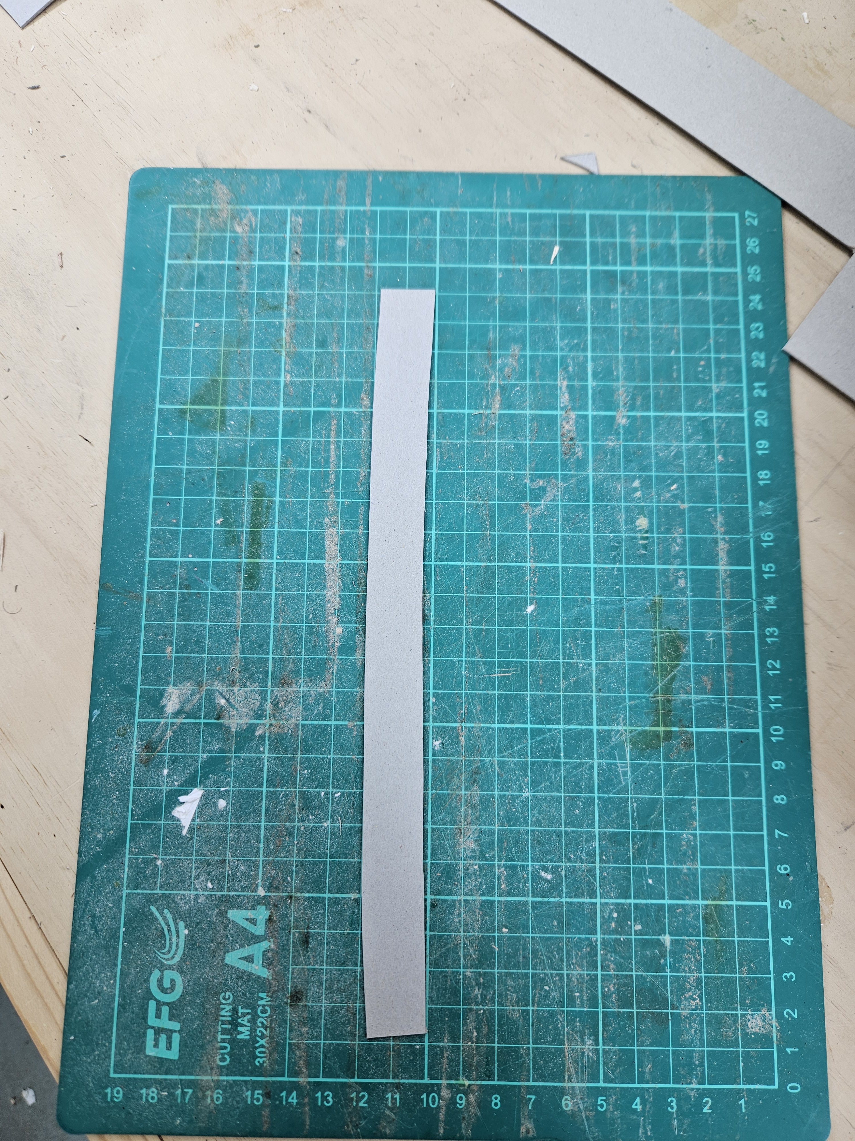
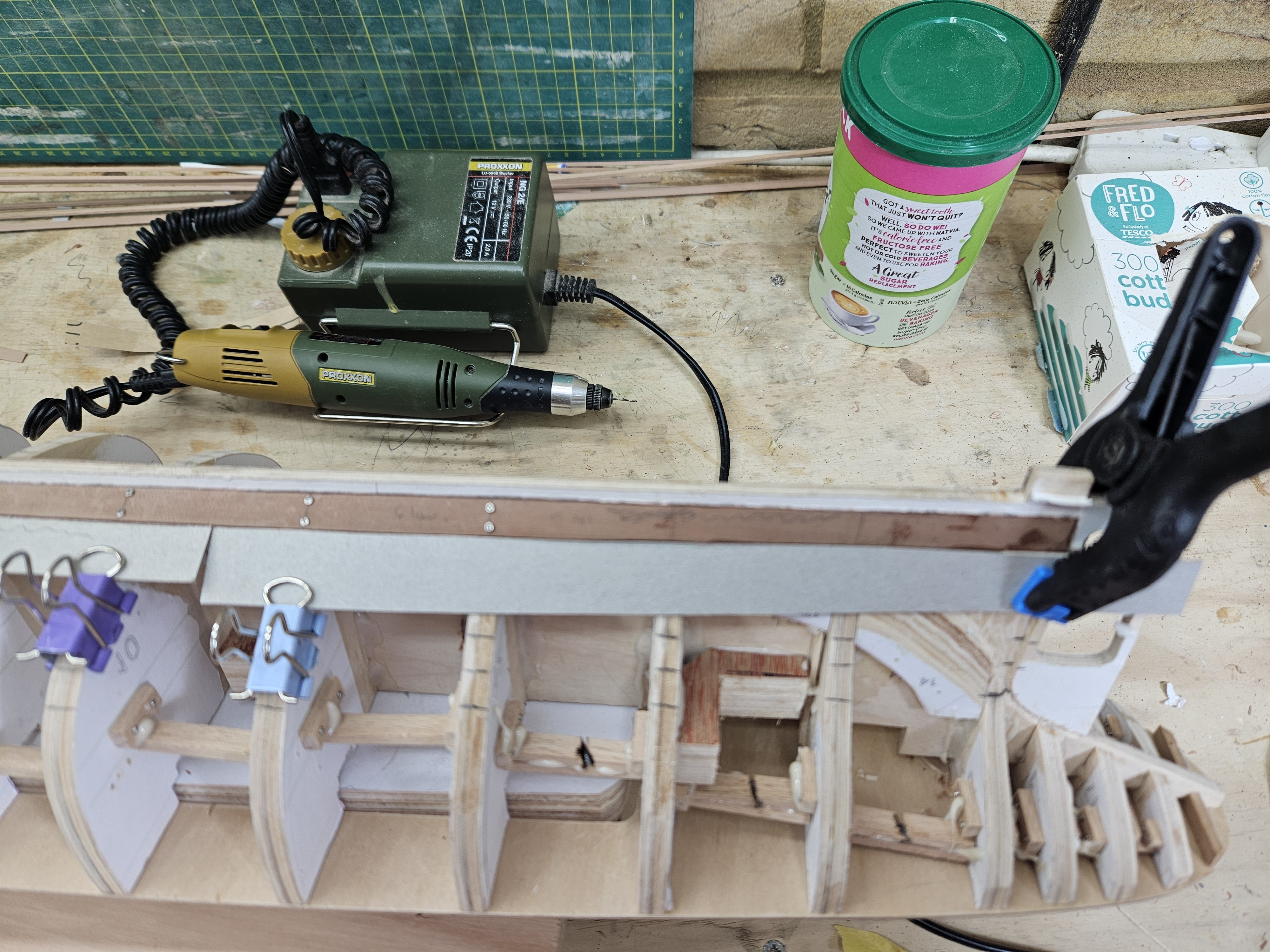
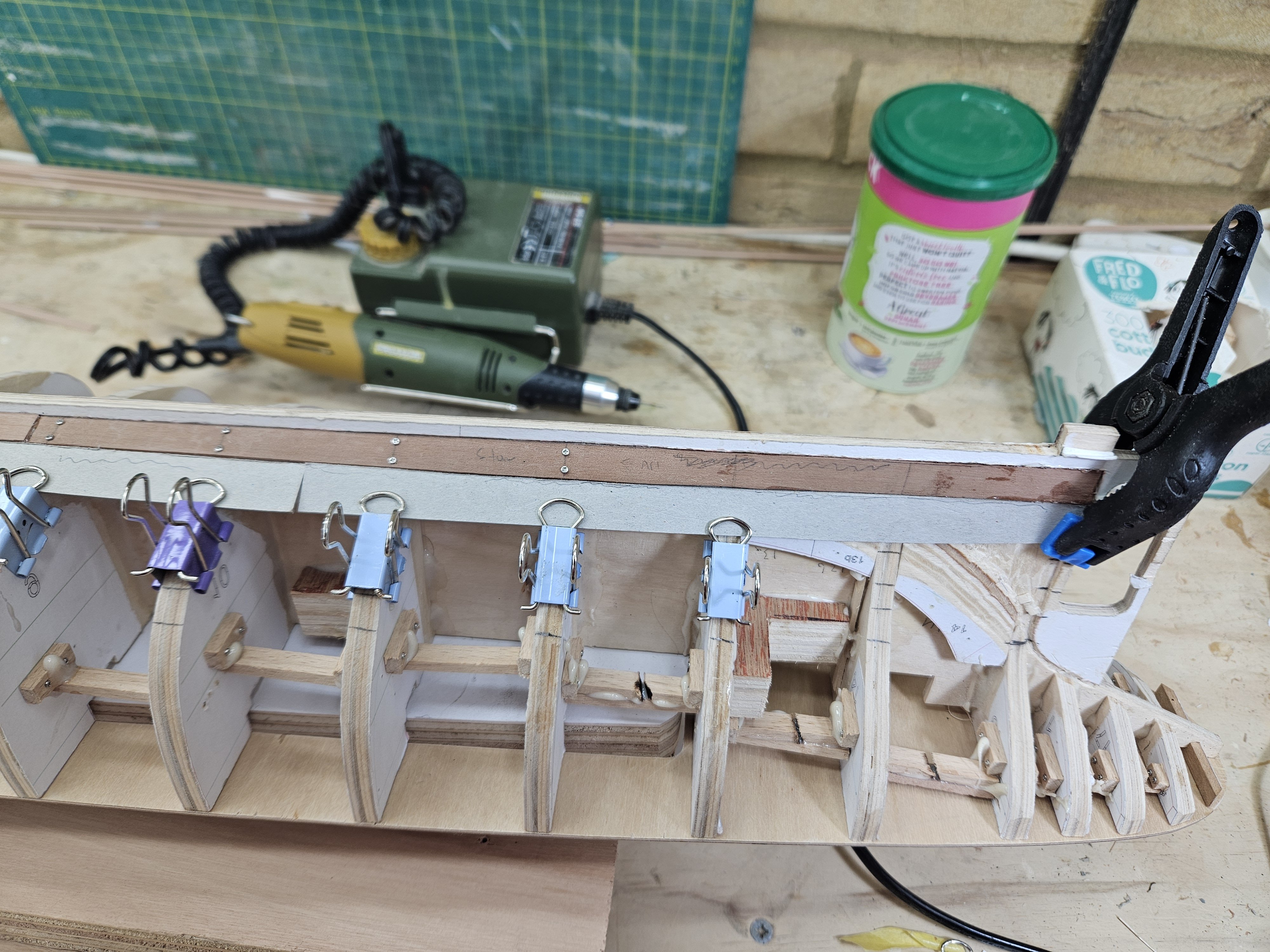
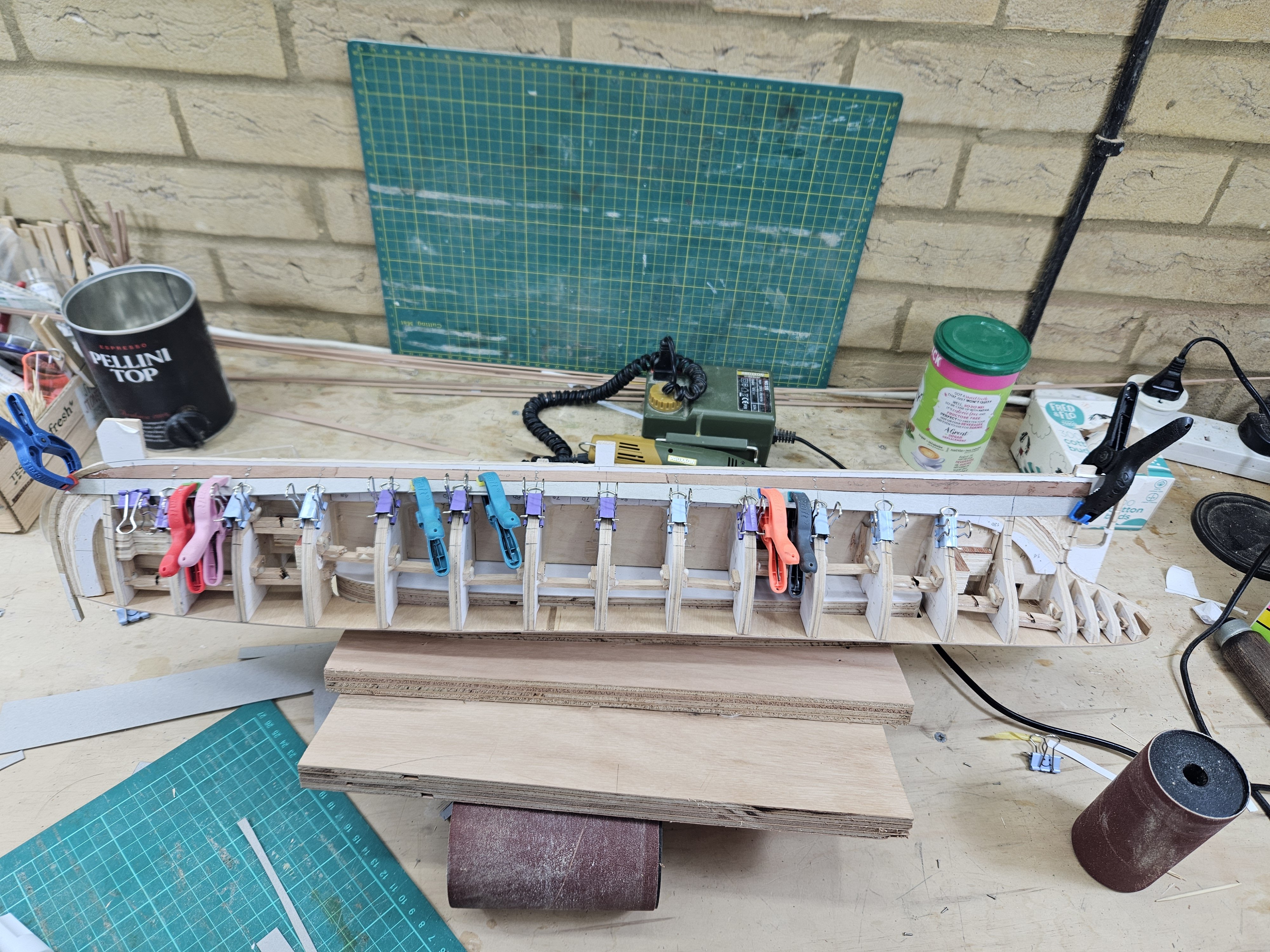
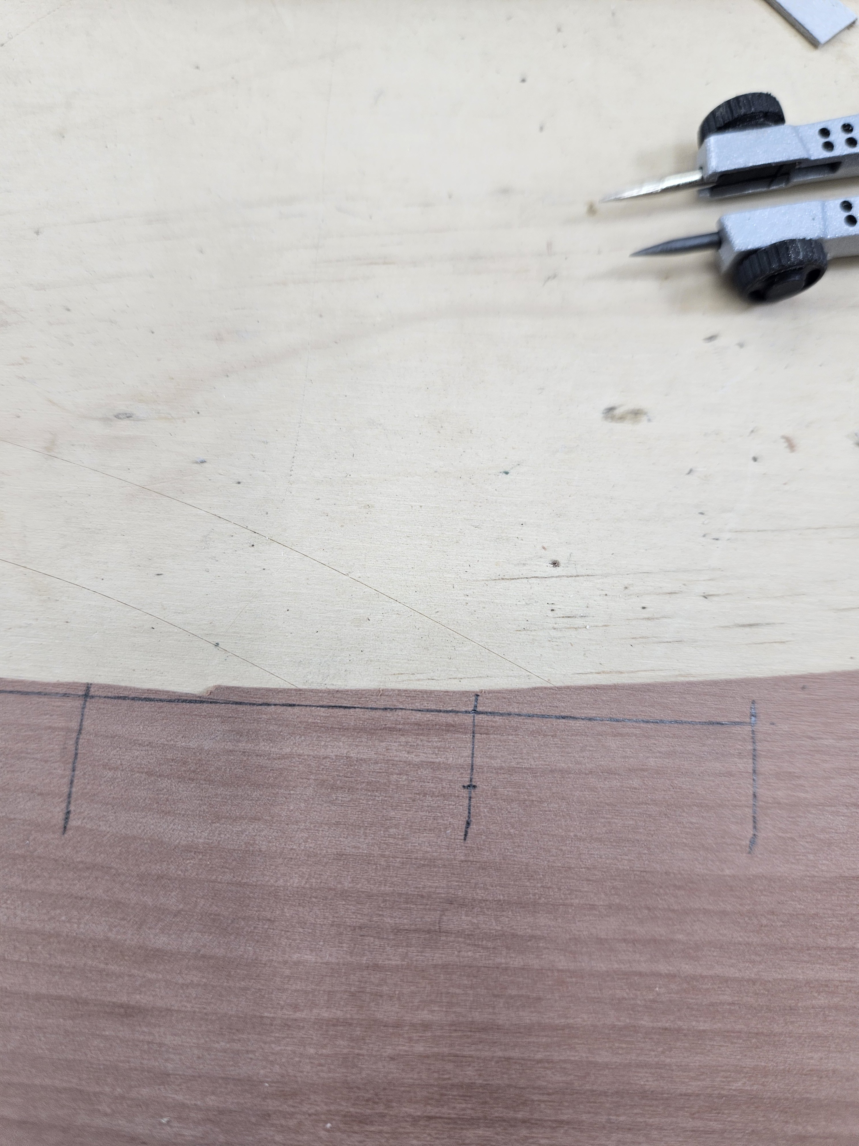
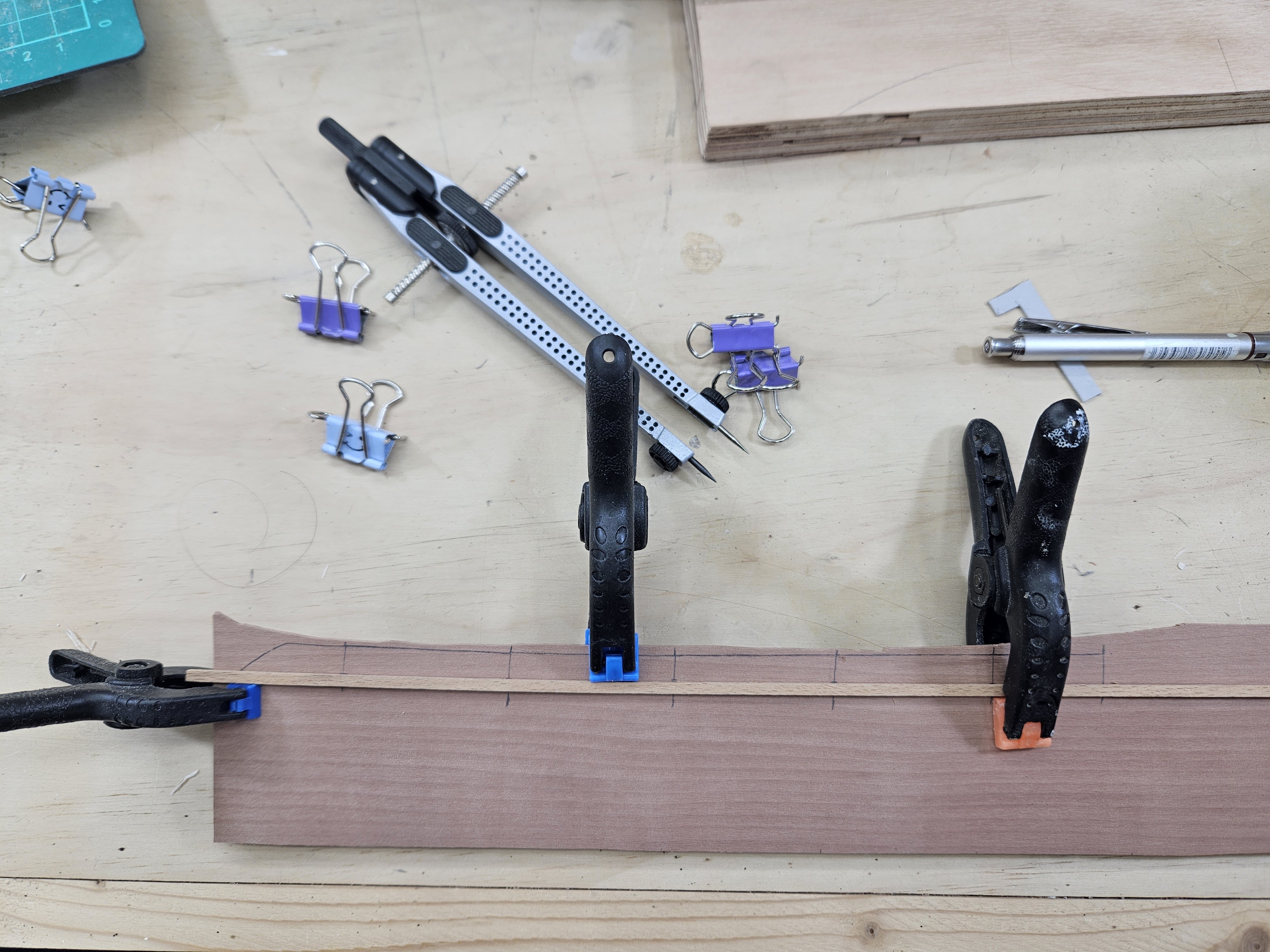
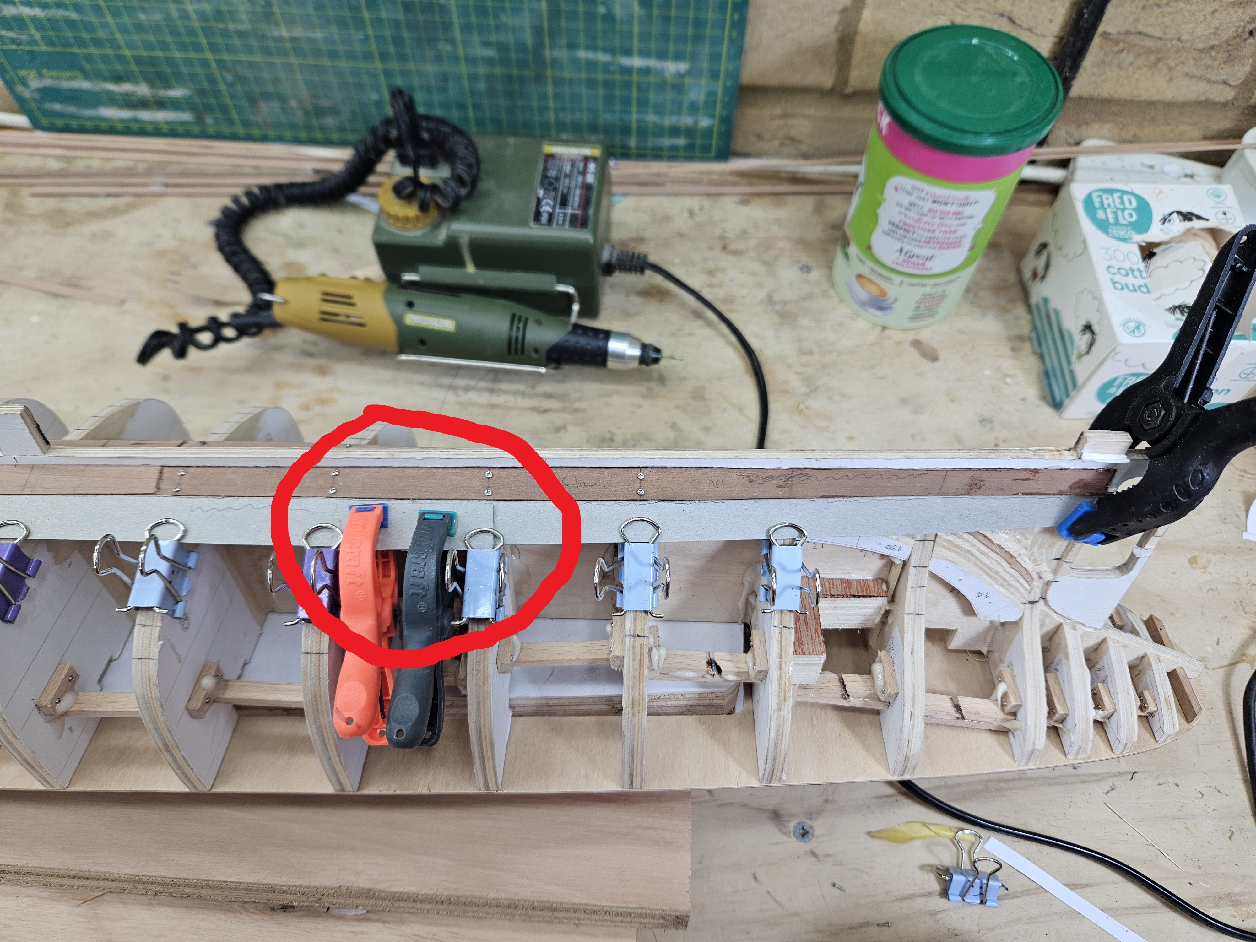
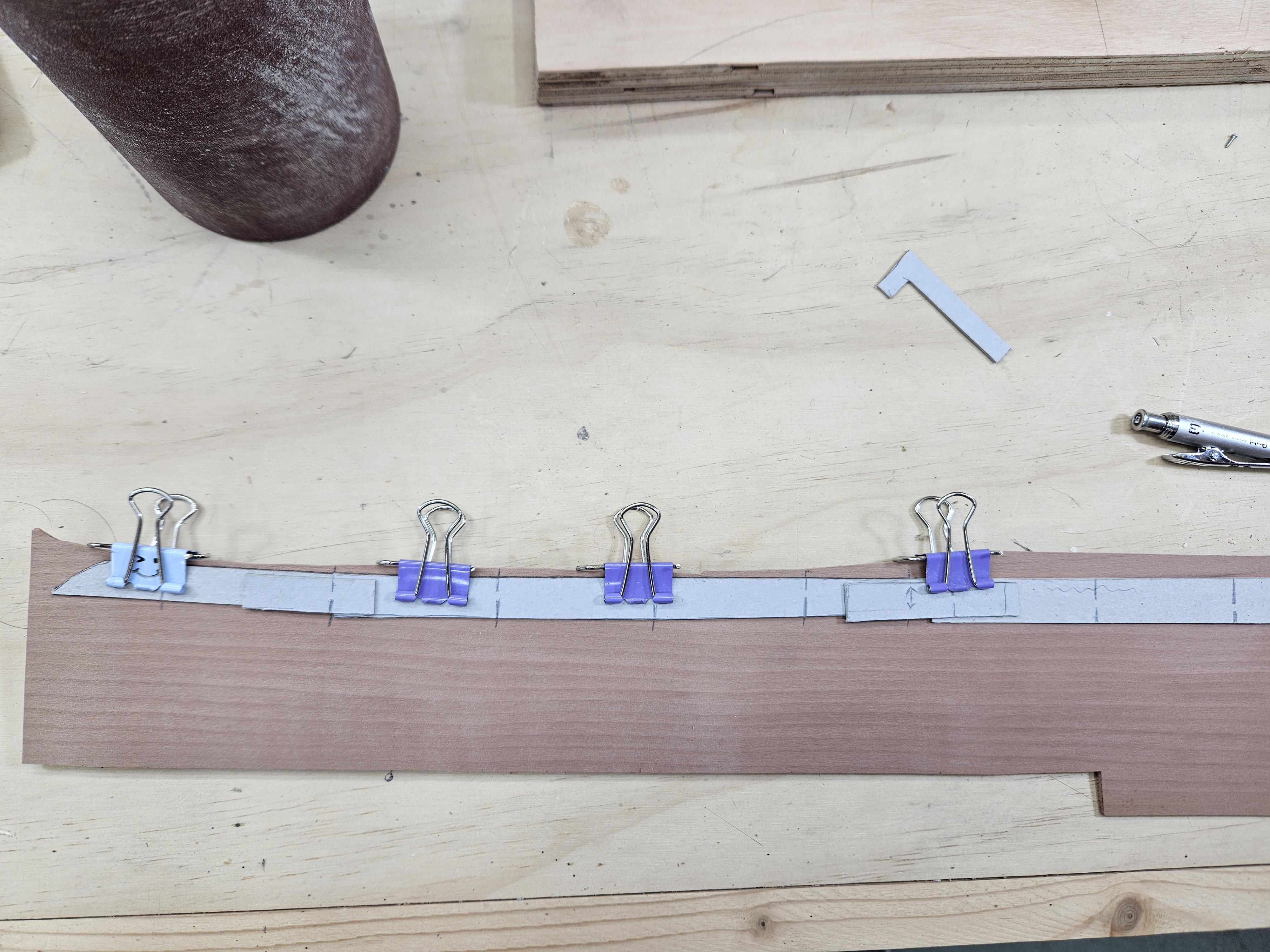
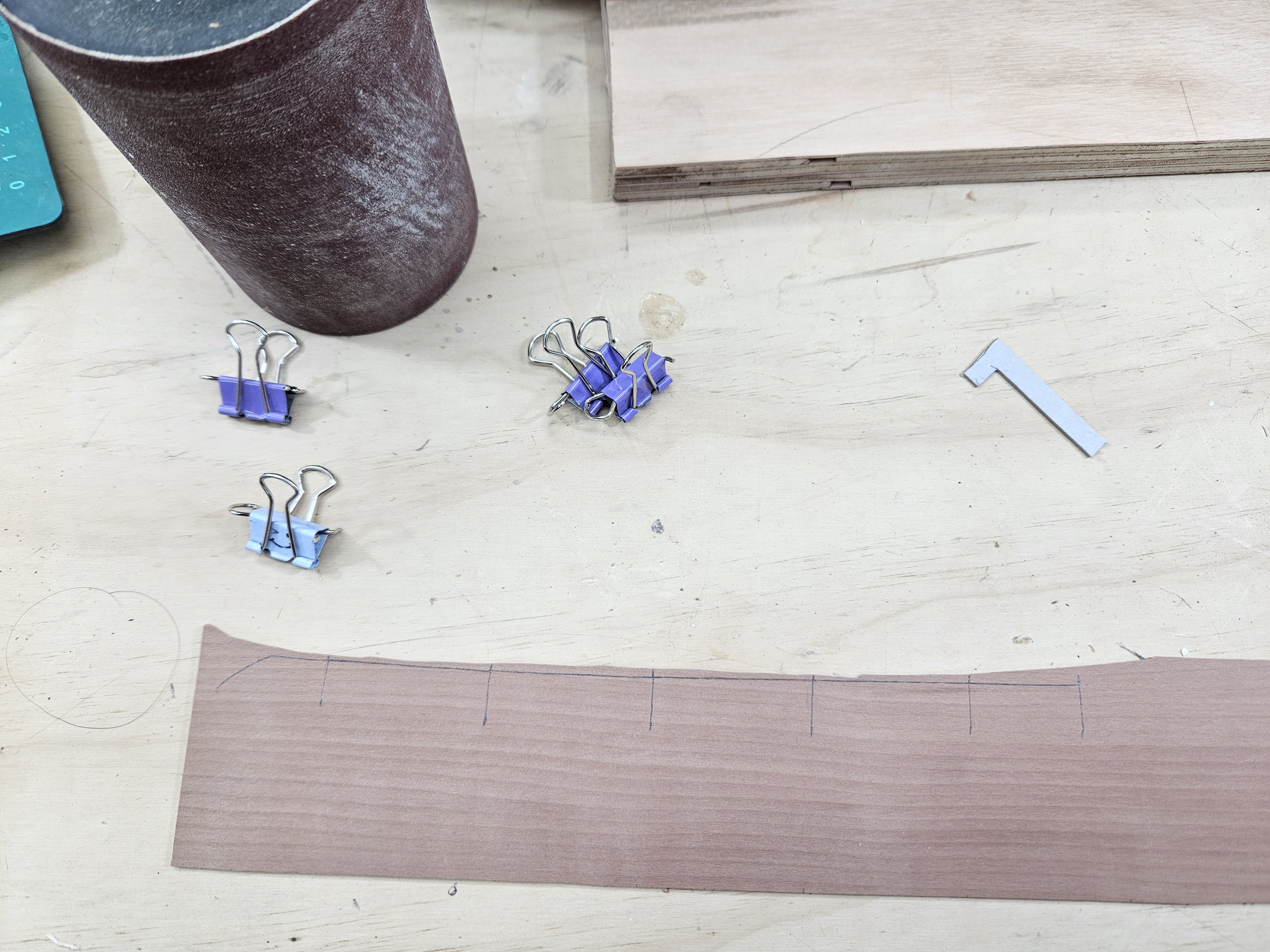
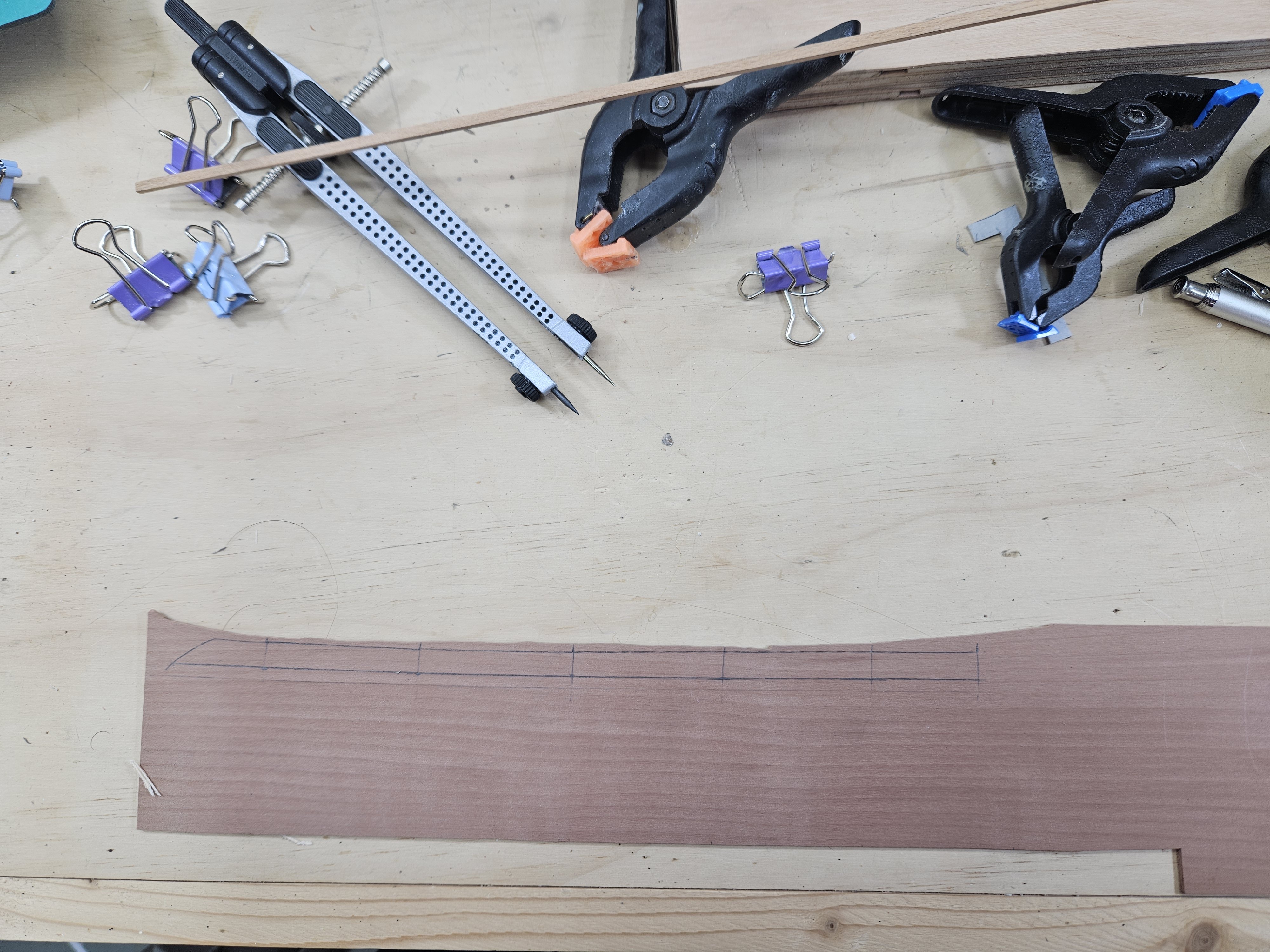
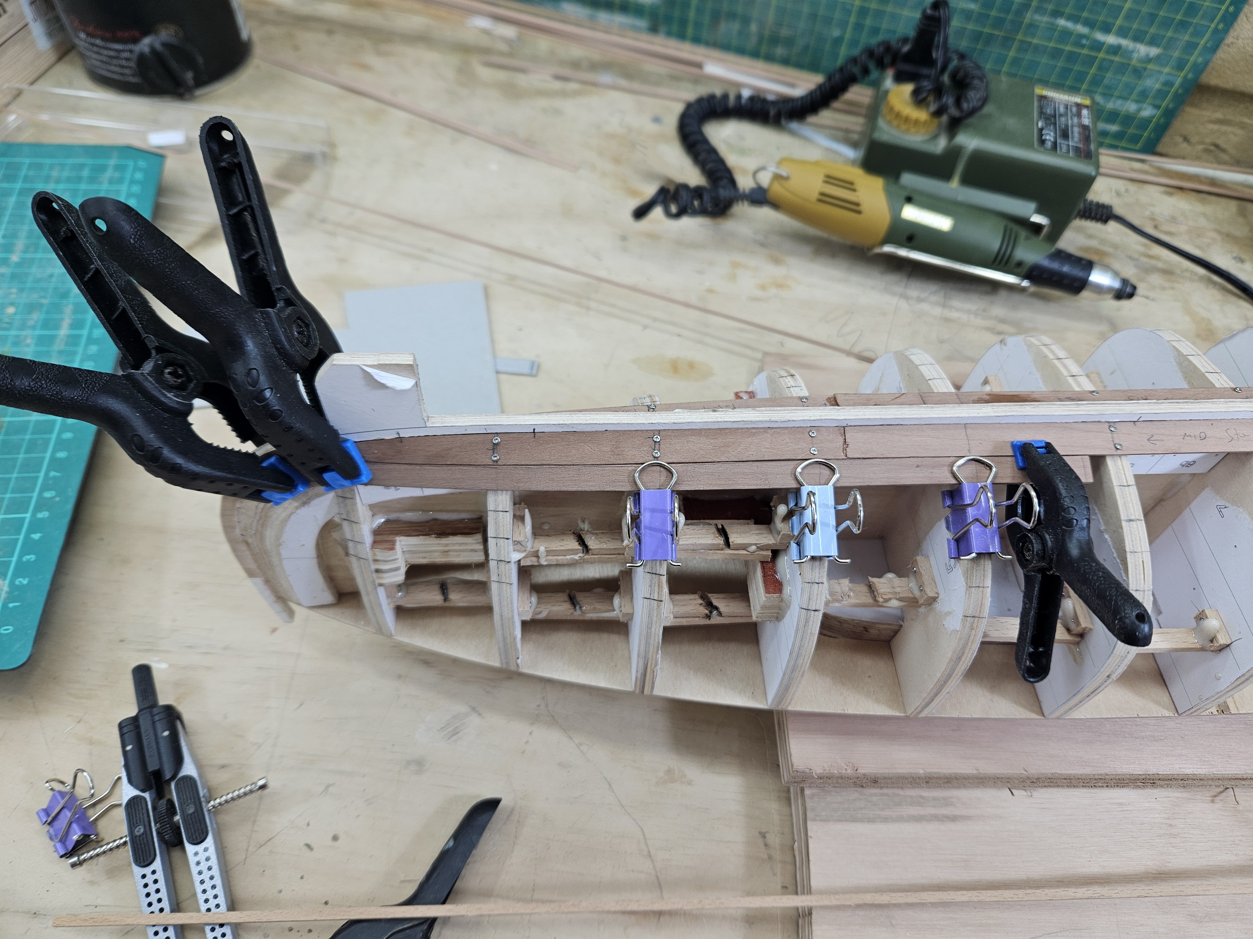
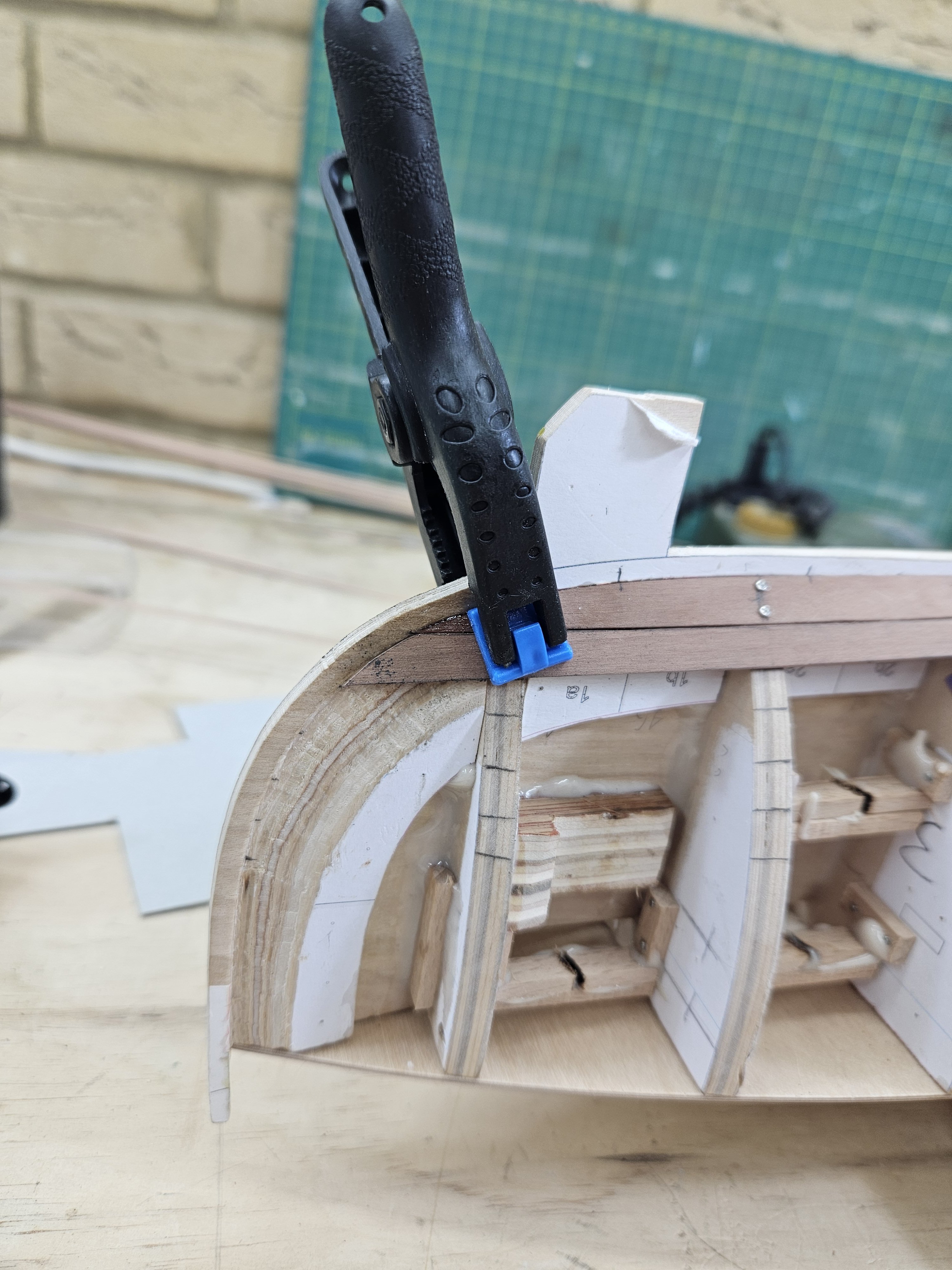
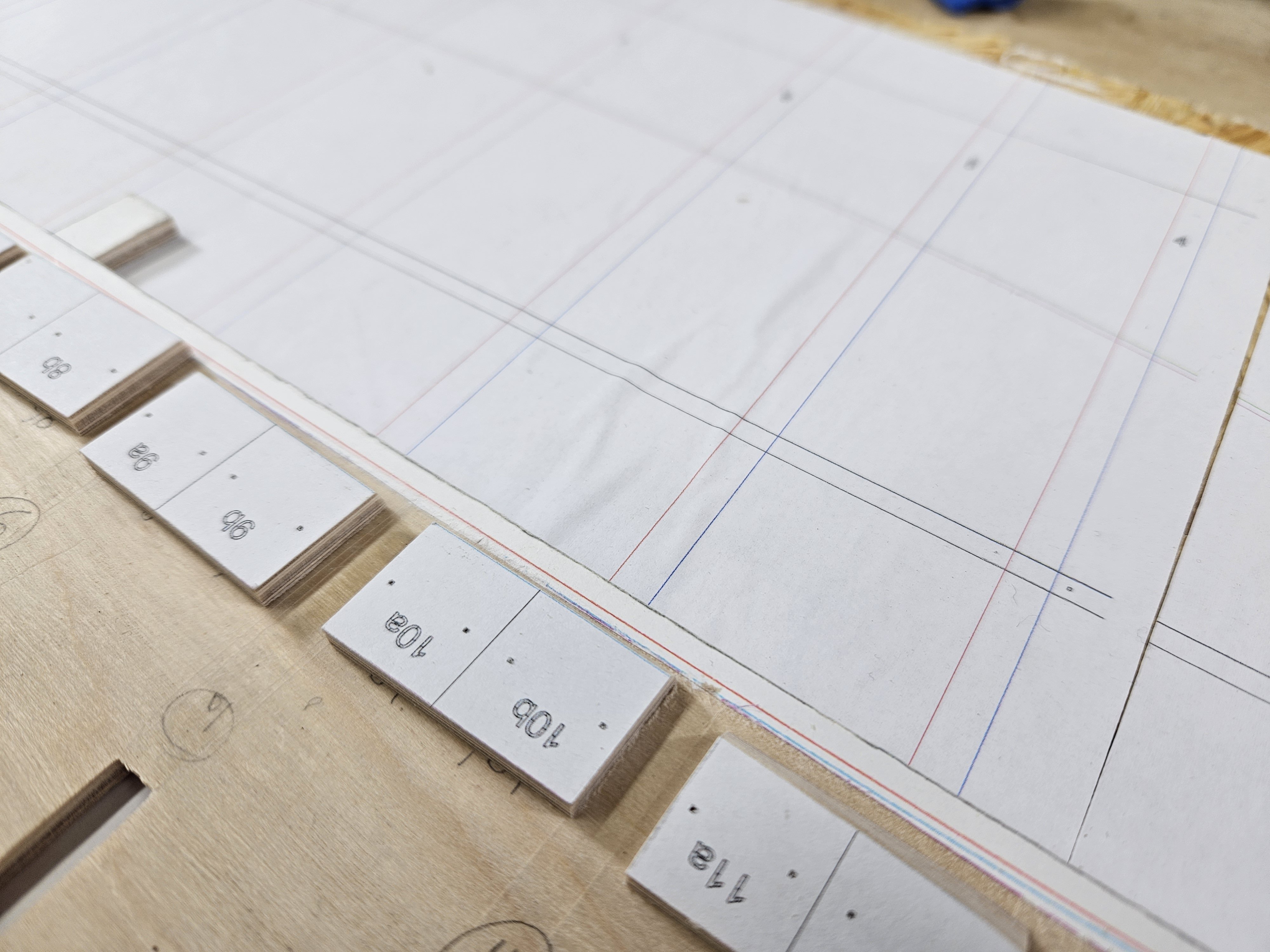
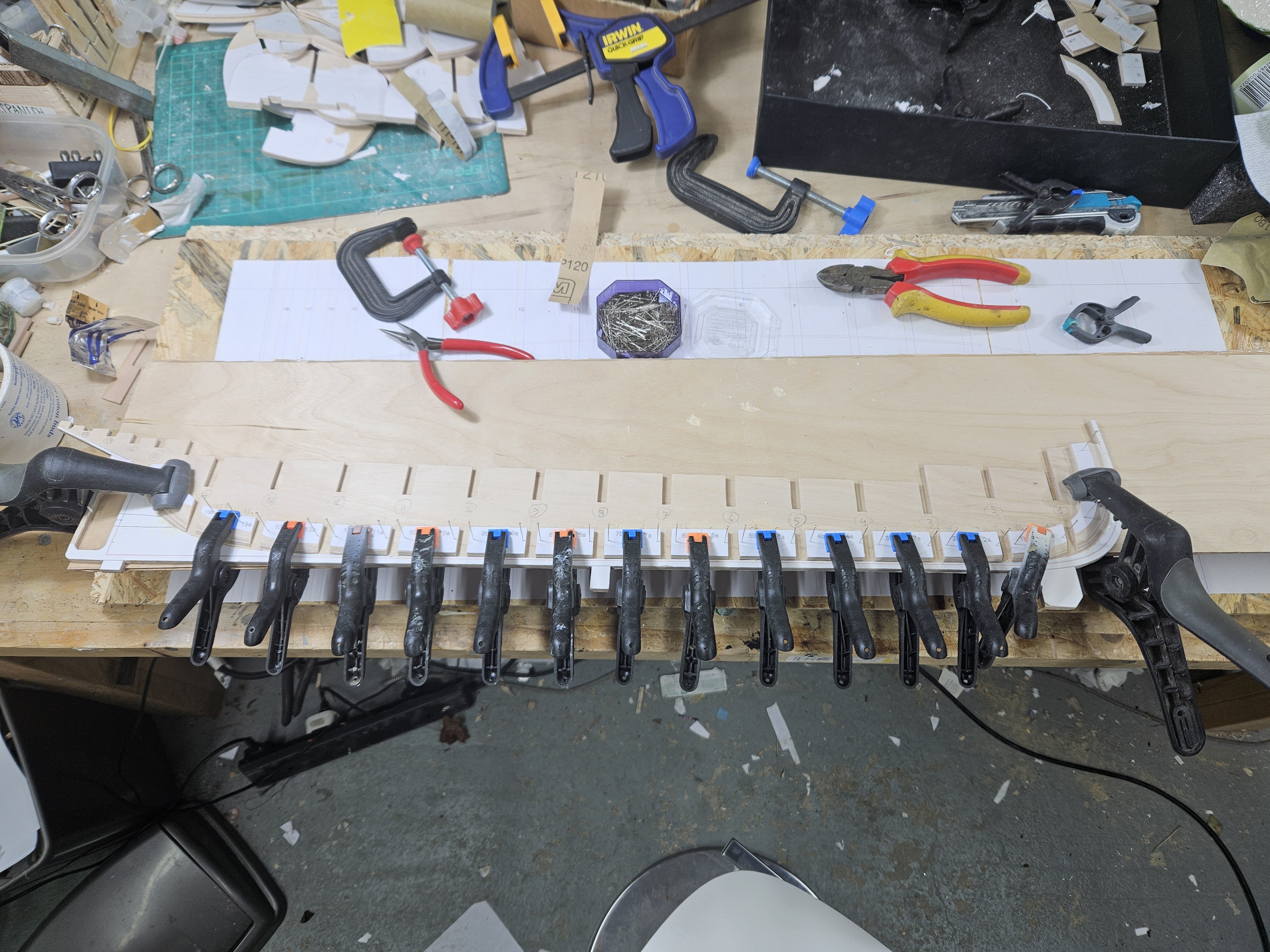
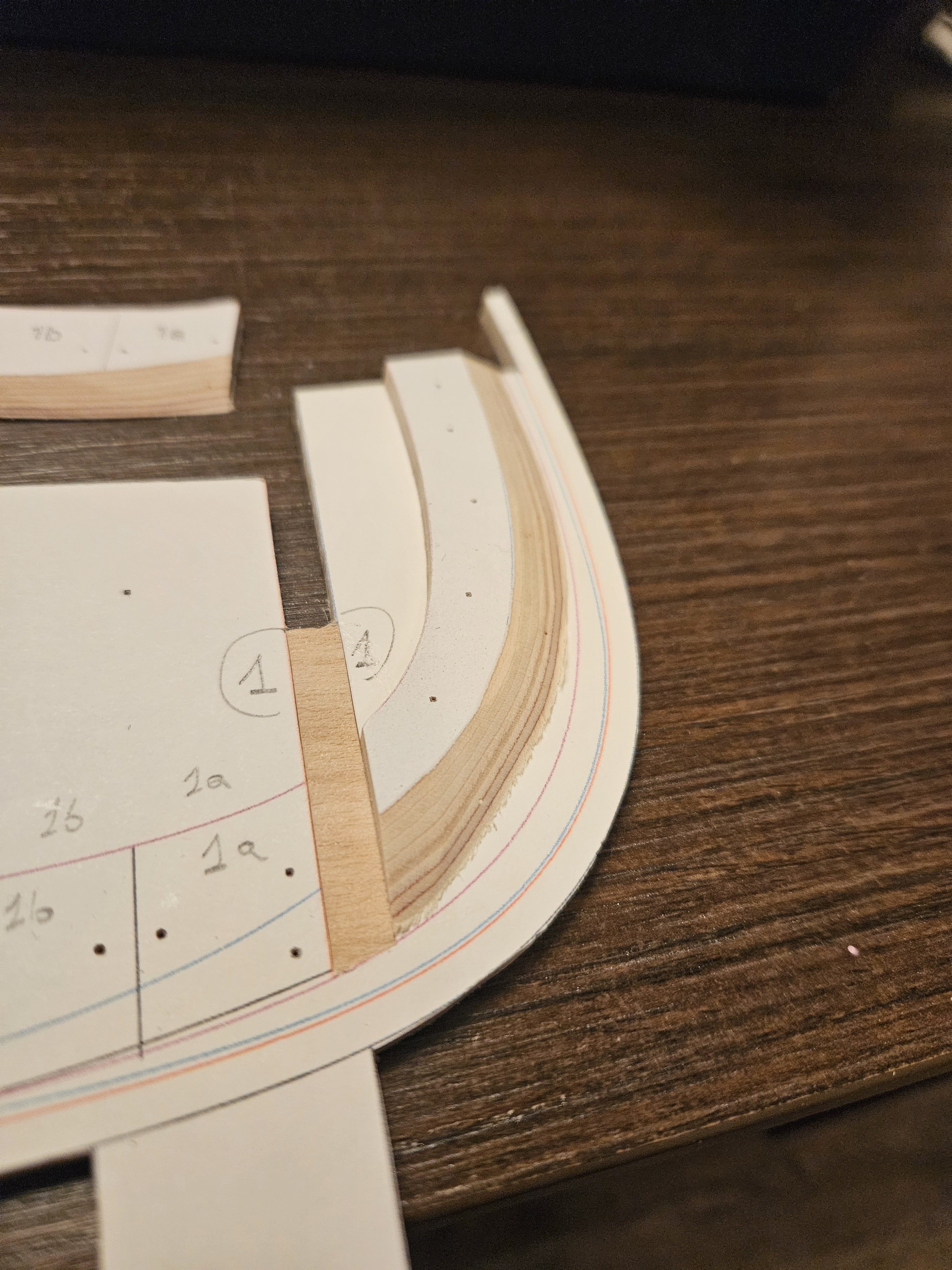
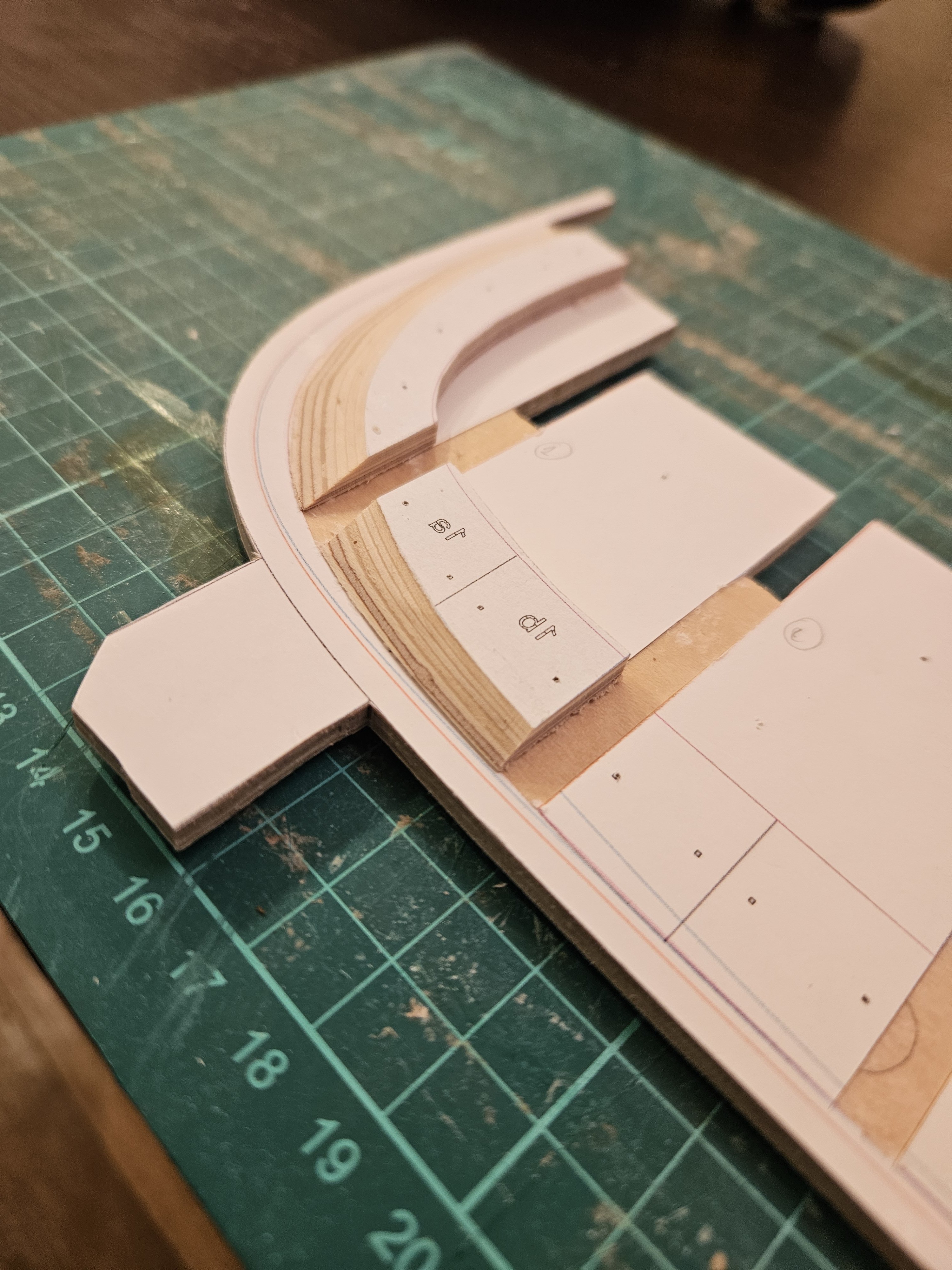
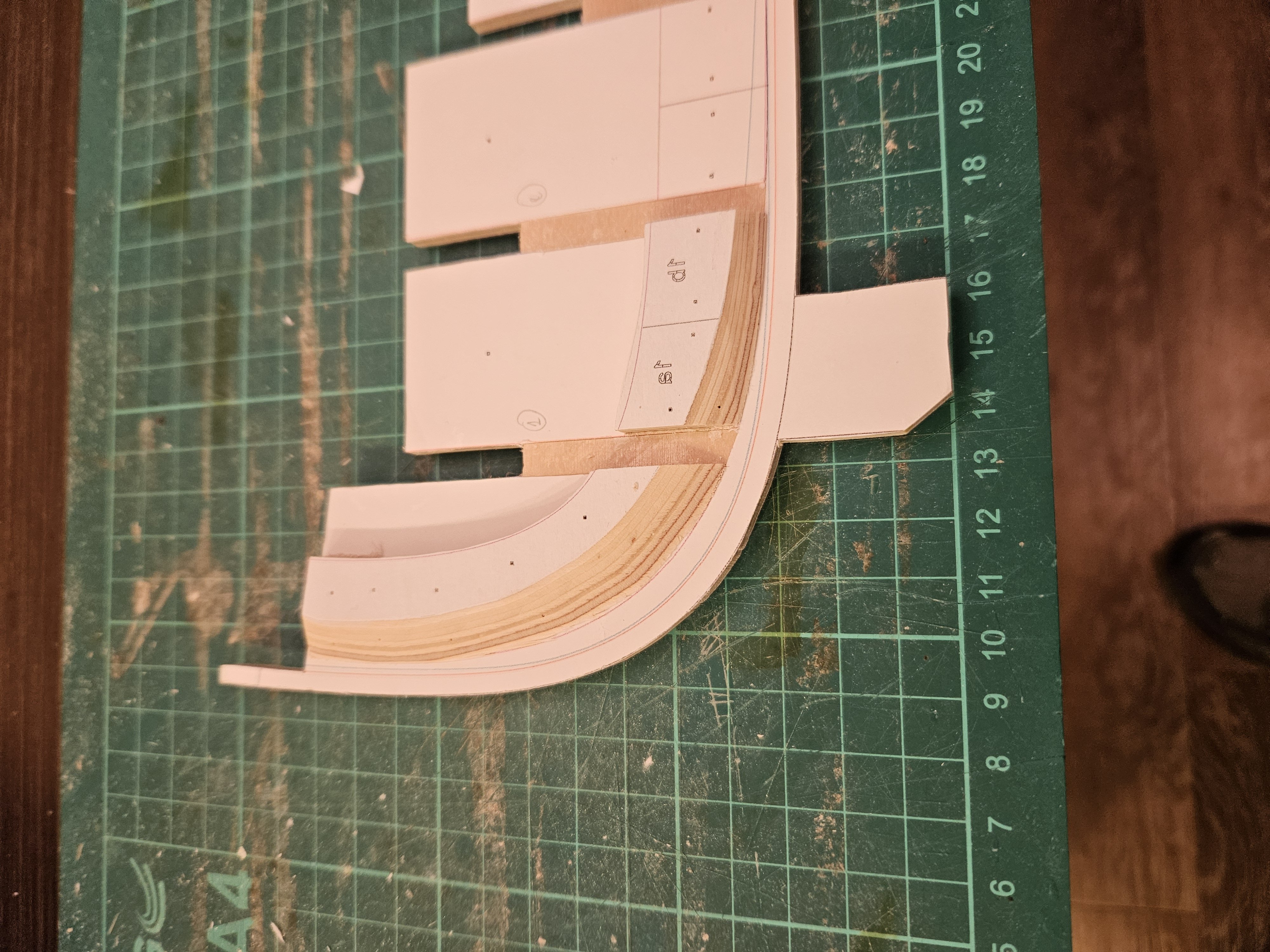
Thank you all for your likes and replies and taking the time to visit. @Jim Lad Jim it really makes a big difference, having the extra real estate around the saw but figuring out how to make the bench was a pain! @Bedford I could and should have used 0.8 ply but I had already finished the CAD design, it would need more frames and most importantly true 0.8 mm seems to have disappeared - most of it apparently comes from Russia. Good to know though that Scissors can cut it cleanly - never thought of it. Def one to remember. Now, lets talk Planking! I cut both garboards and steamed them in place. I ve never steamed pear wood but it responded superbly. I used my steam box to heat the planks - worked really well. I then scarfed the ends and secured in place with screws, The ends however had to be glued as the hull is not thick enough. Due to uneven surfaces I used epoxy - very messy solution but I do not think there is another. I think they came out alright! I really like planking. For this boat, I did not really spend much time planning, I just eyeballed it a bit. I have only marked half of the hull but I feel pretty confident. So let me share my method of spilling planks. First I use 1mm (or 1.5 I am not sure) cardboard to make a pattern. I am only interested in the side of the plank that meets the plank already installed. The foreword part of the plank has a lot of twist along its axis. To get the correct shape of the edge, cut a strip of cardboard roughly the correct shape and run dividers along the edge of the plank already installed. Then cut along the line with a knife Fitting the pattern, it is a bit off - mark the high spots Lightly sand the high spots, fit again, sand again etc. Now it fits fine Connect with the previous plank using cardboard and glue and move on to next segment. For the aft segment, the process is repeated - it just happened my rough cut pattern was spot on here! The plank is now completed - the upper edge that is Usually, I would just cut the plank as a single very long one but I would like to reduce wastage of wood. So now lets cut the individual segments. First we transfer the shape of the upper edge to wood, making sure we mark the positions of the frames. Then we measure the distances from edge of previous plank to line on frame and transfer over to wood Using a baten, we connect the marks making sure the line is fair Our plank segment is ready Next cut the plank, test fit, mark and sand any high spots, fit again etc. Later on we will need to also take into account bevels and also curvature of frames - either sand concave the inner surface of planks or sand flat the frames. Same process for middle and aft segments All segments are ready, just the scarfs are needed. The plank on the other side needs to be again cut individually as it is a close but not exact fit. On a different boat I would have spent more time arranging the run of the planks but for Hercules, I think this will work well - the plank shape so far does not seem horrible. I hope this was interesting! Till next time Vaddoc


-
Best White Wood Glue For Ship Building
vaddoc replied to OldeManToad's topic in Modeling tools and Workshop Equipment
Phil, I presume this is a variation of contact cement/adhesive? I have not used it all for model building and there does not seem to be a good reason. It should also be gap filling so essentially looks like an epoxy substitute, without the mess. Vaddoc -
Thinning acrylic paints
vaddoc replied to Diver's topic in Painting, finishing and weathering products and techniques
Thinner and retarder! Have a look round MSW, lots of posts in brush painting. -
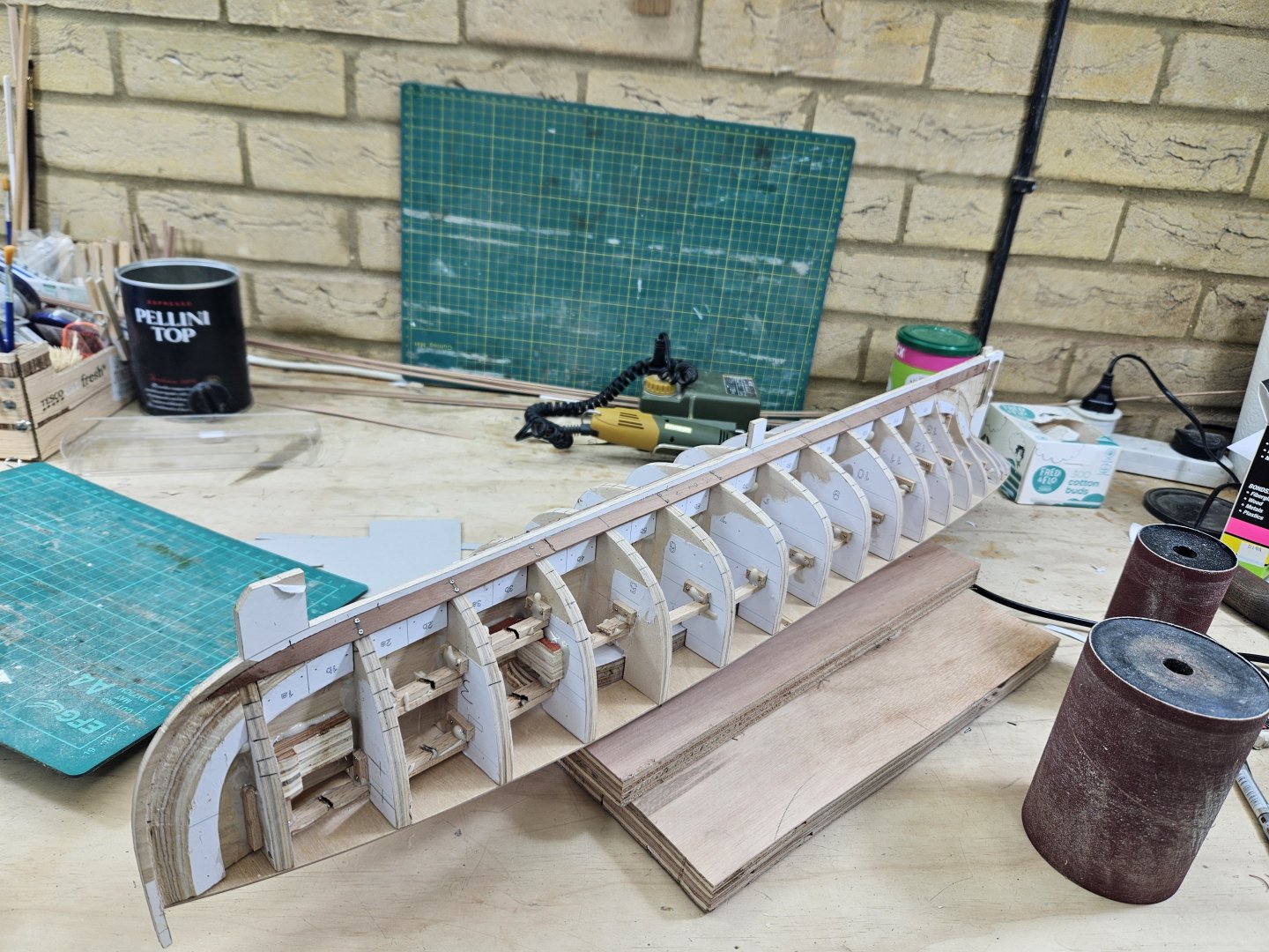
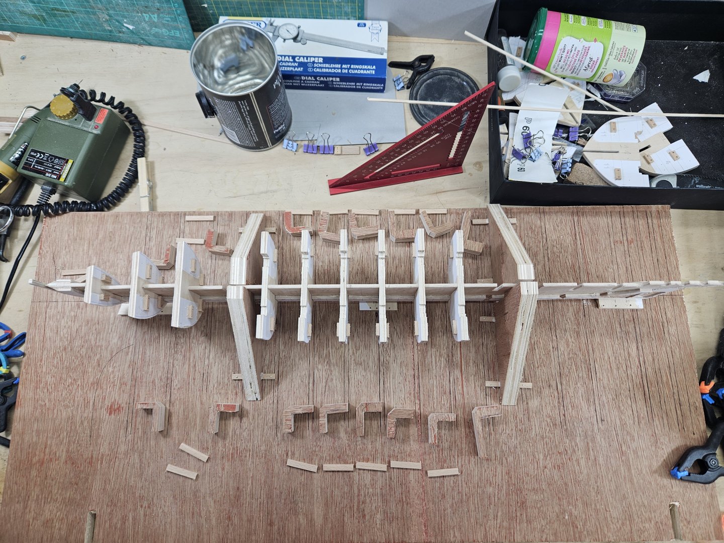
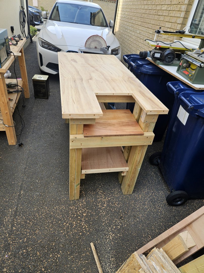
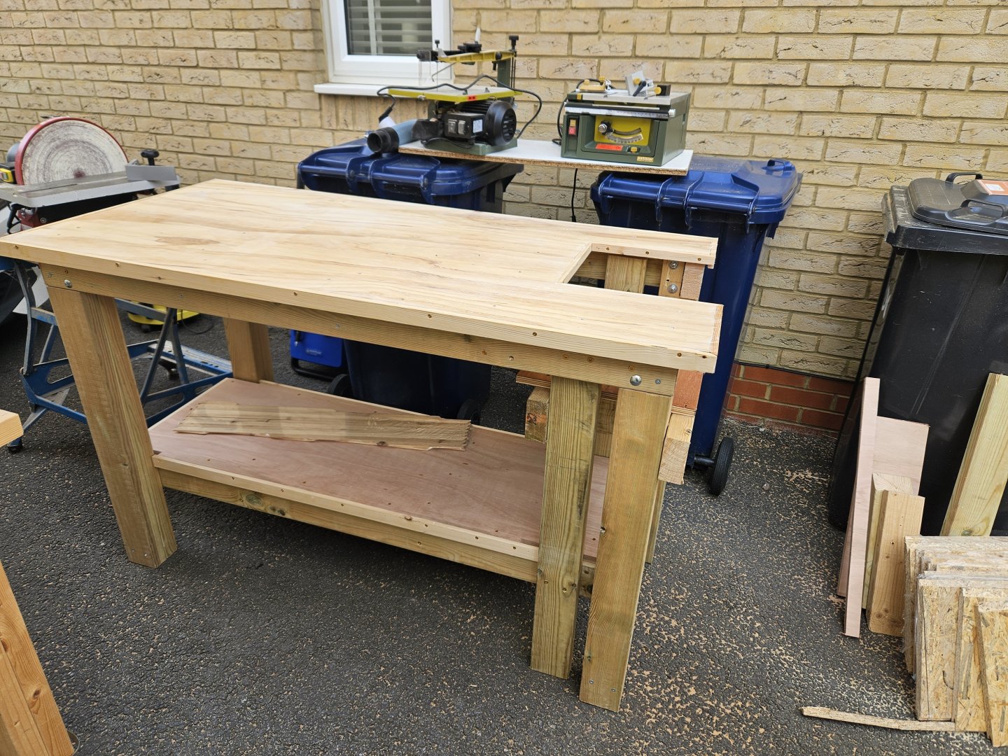
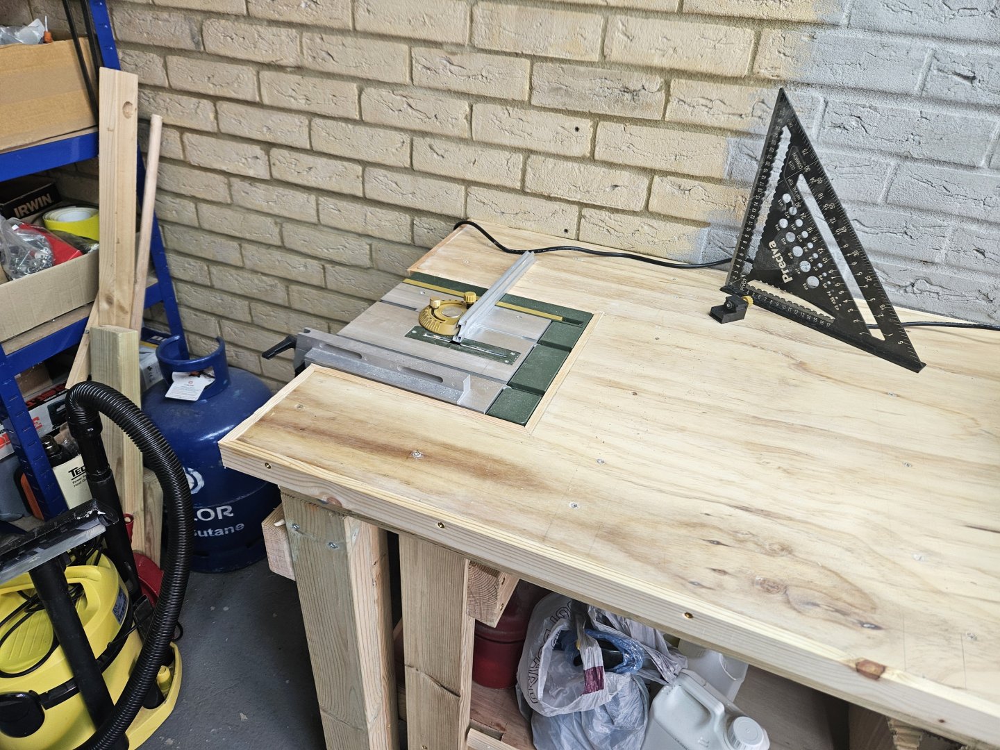
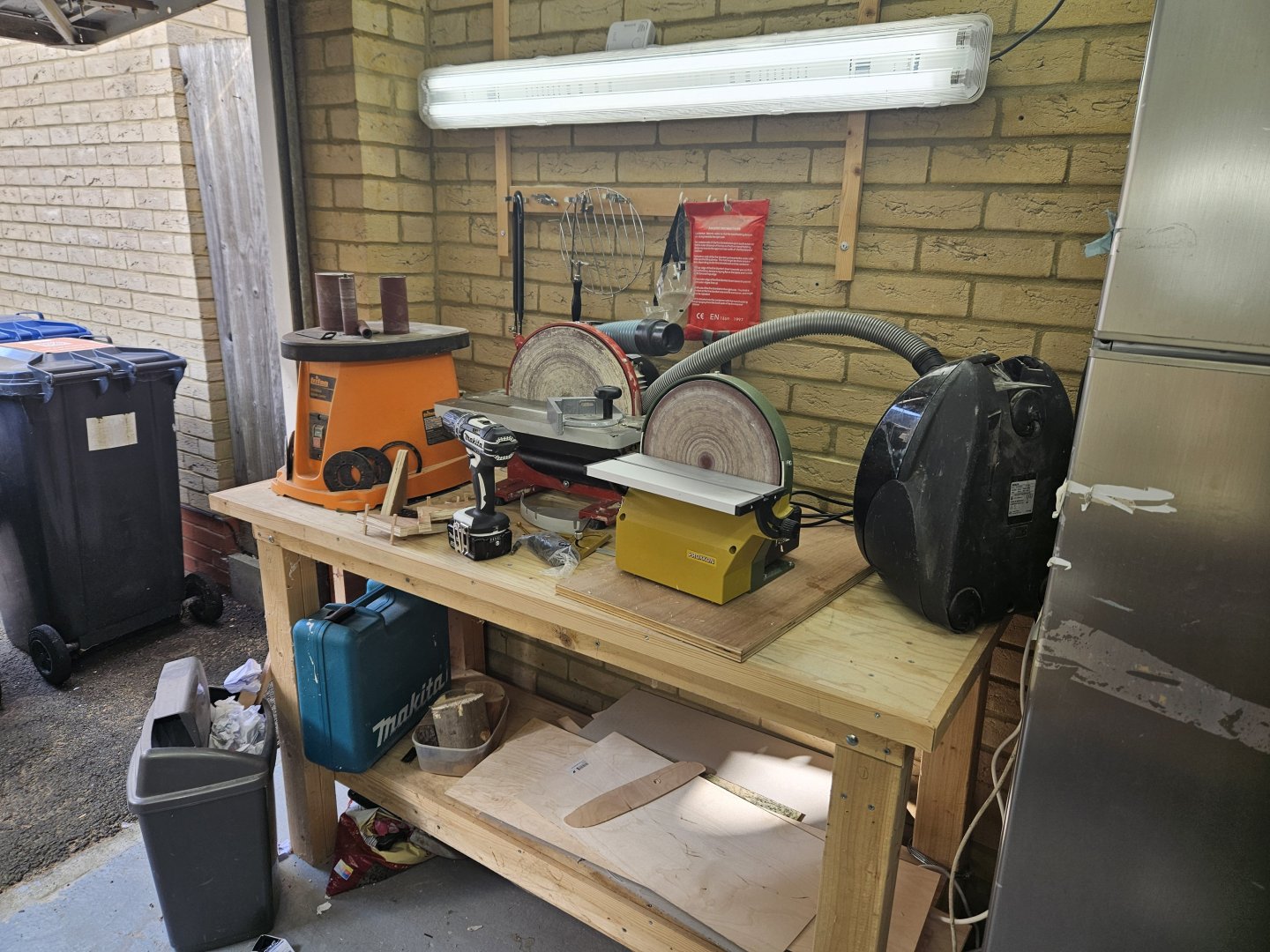
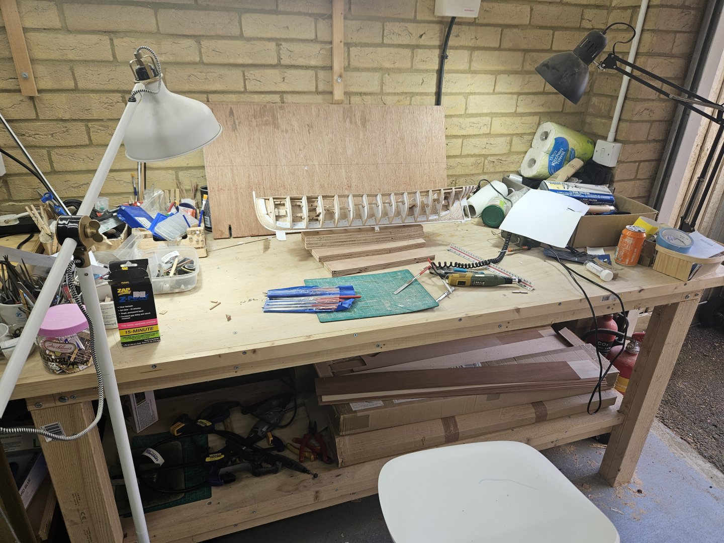
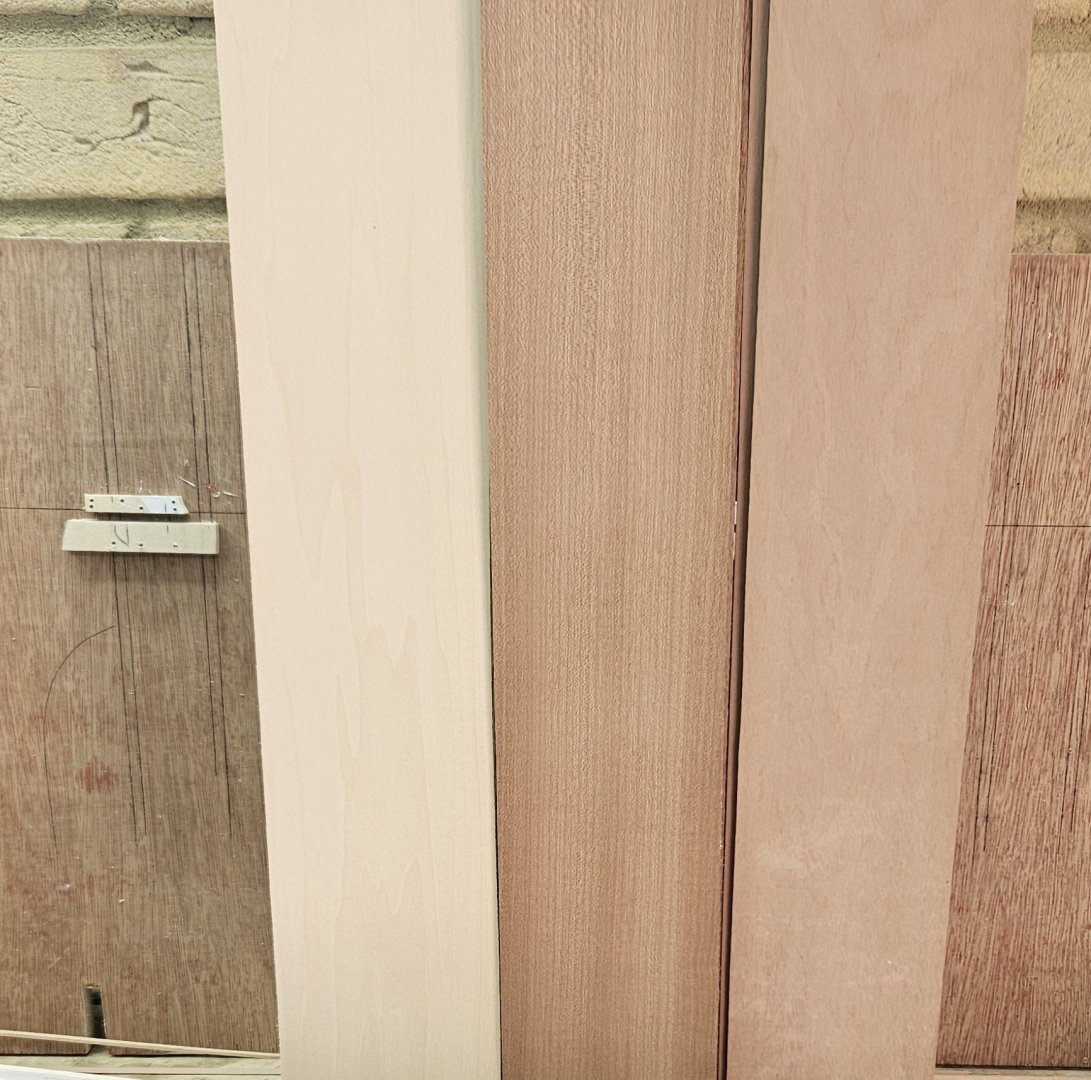
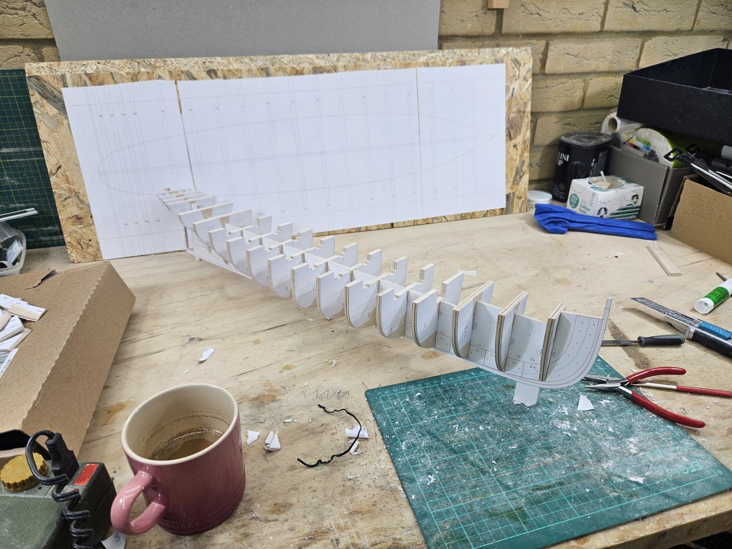
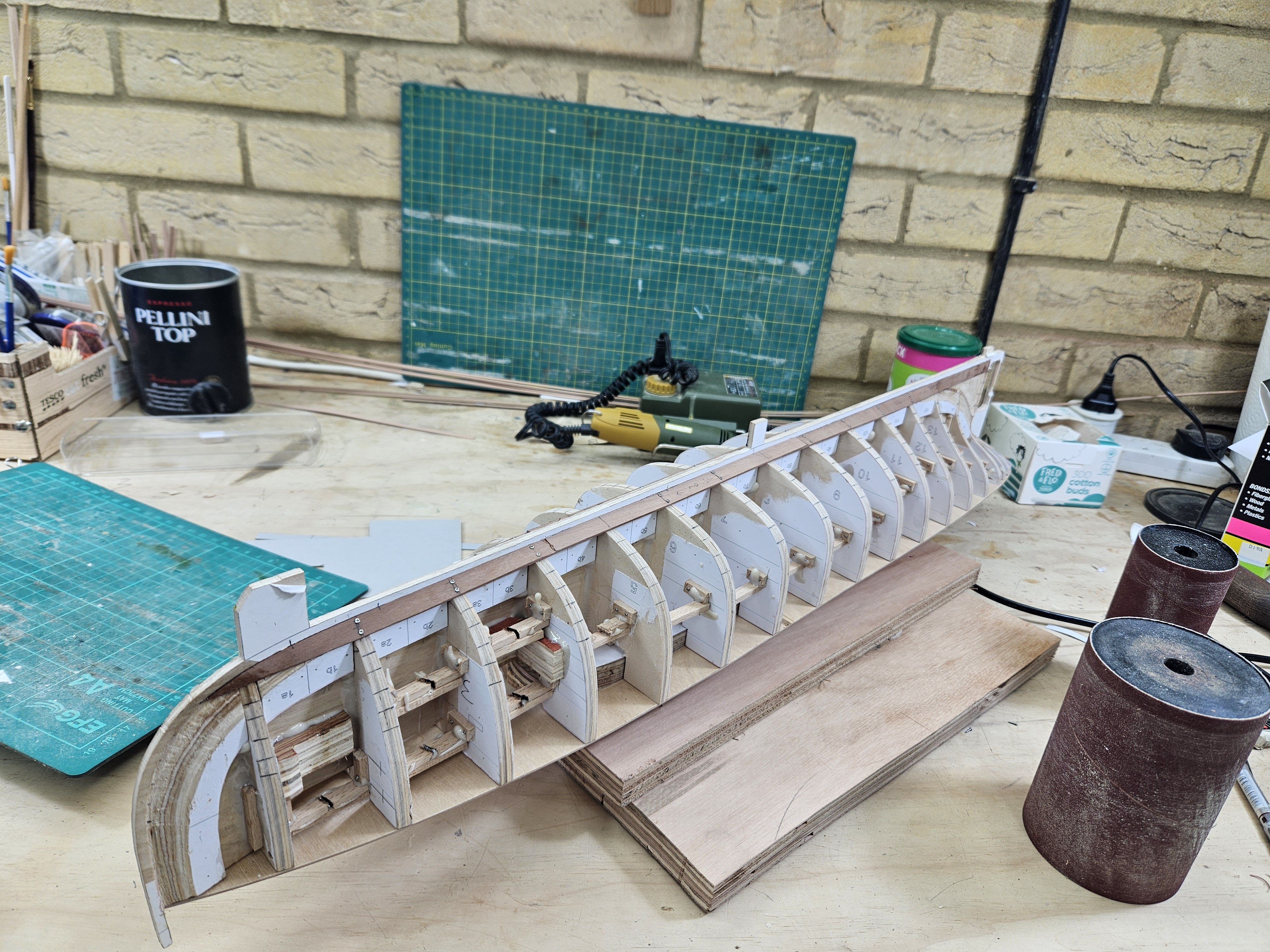
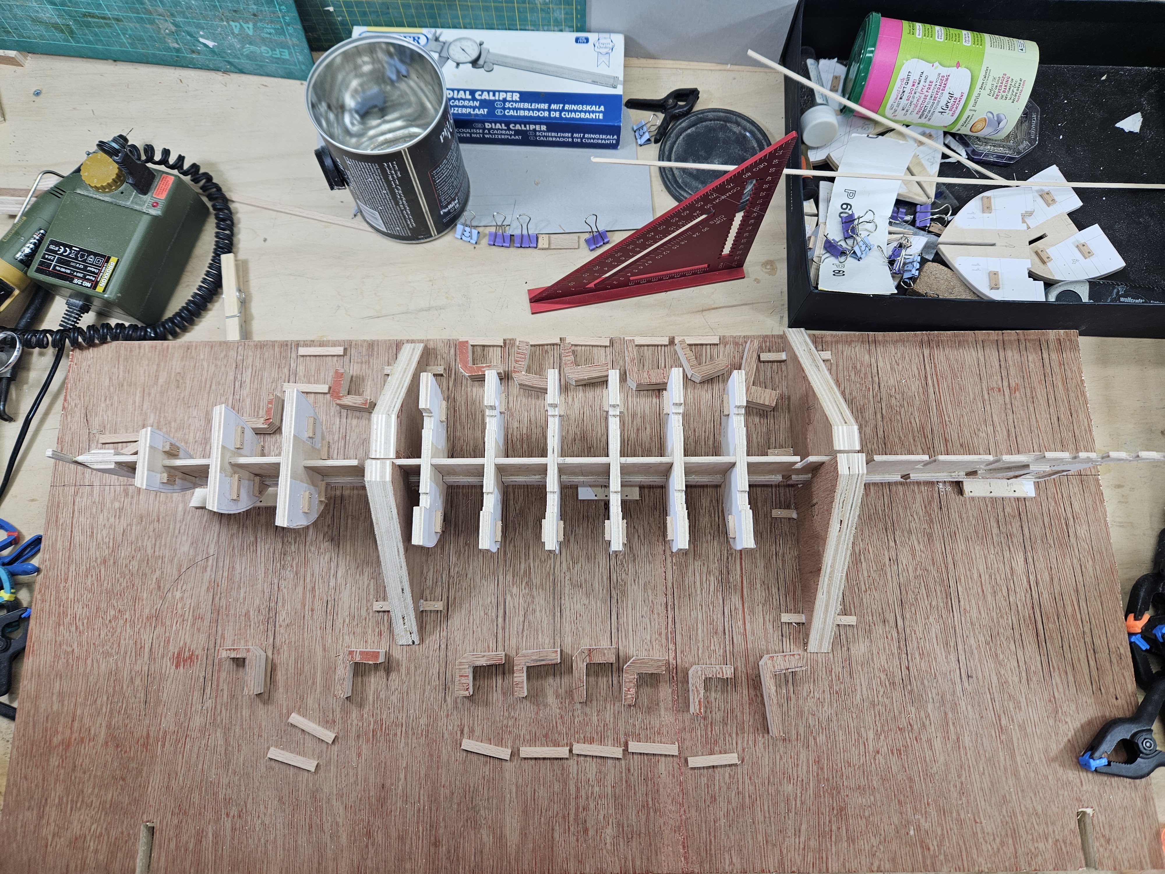
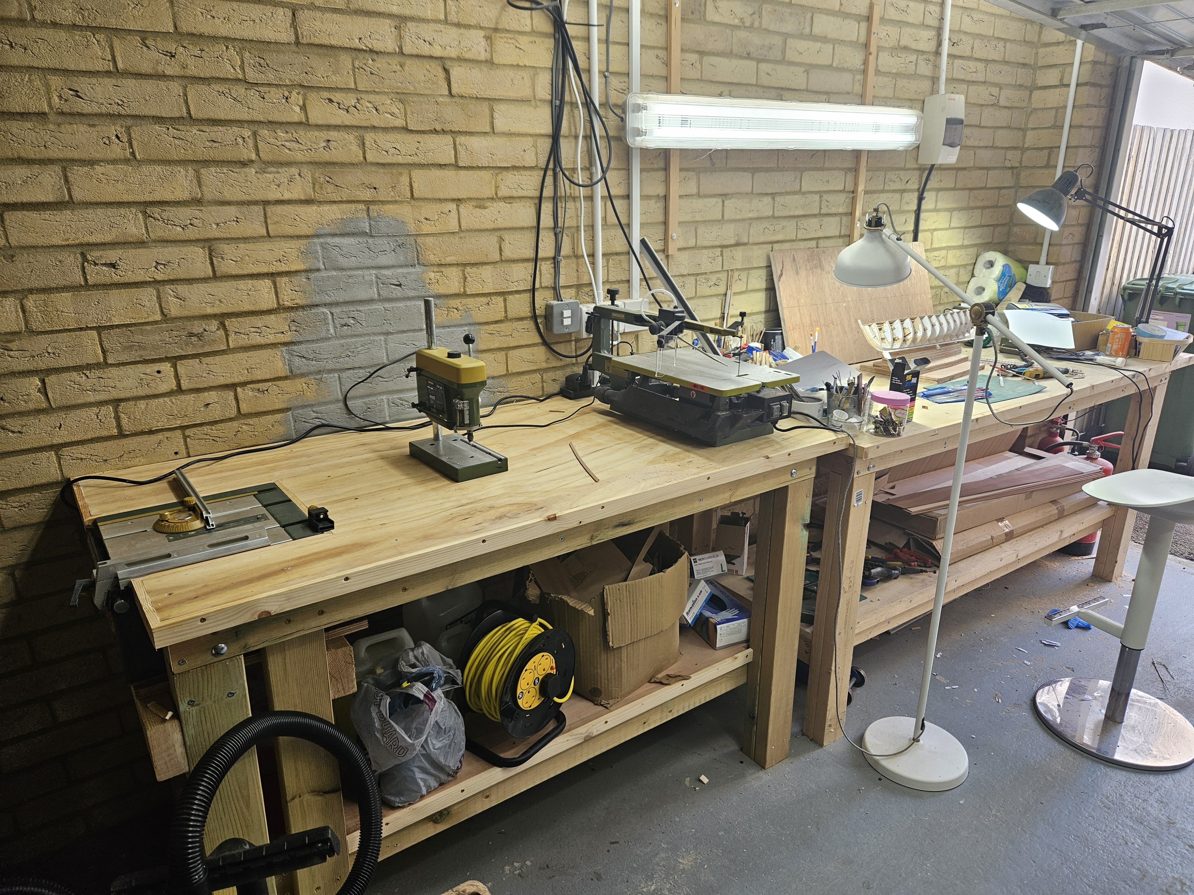
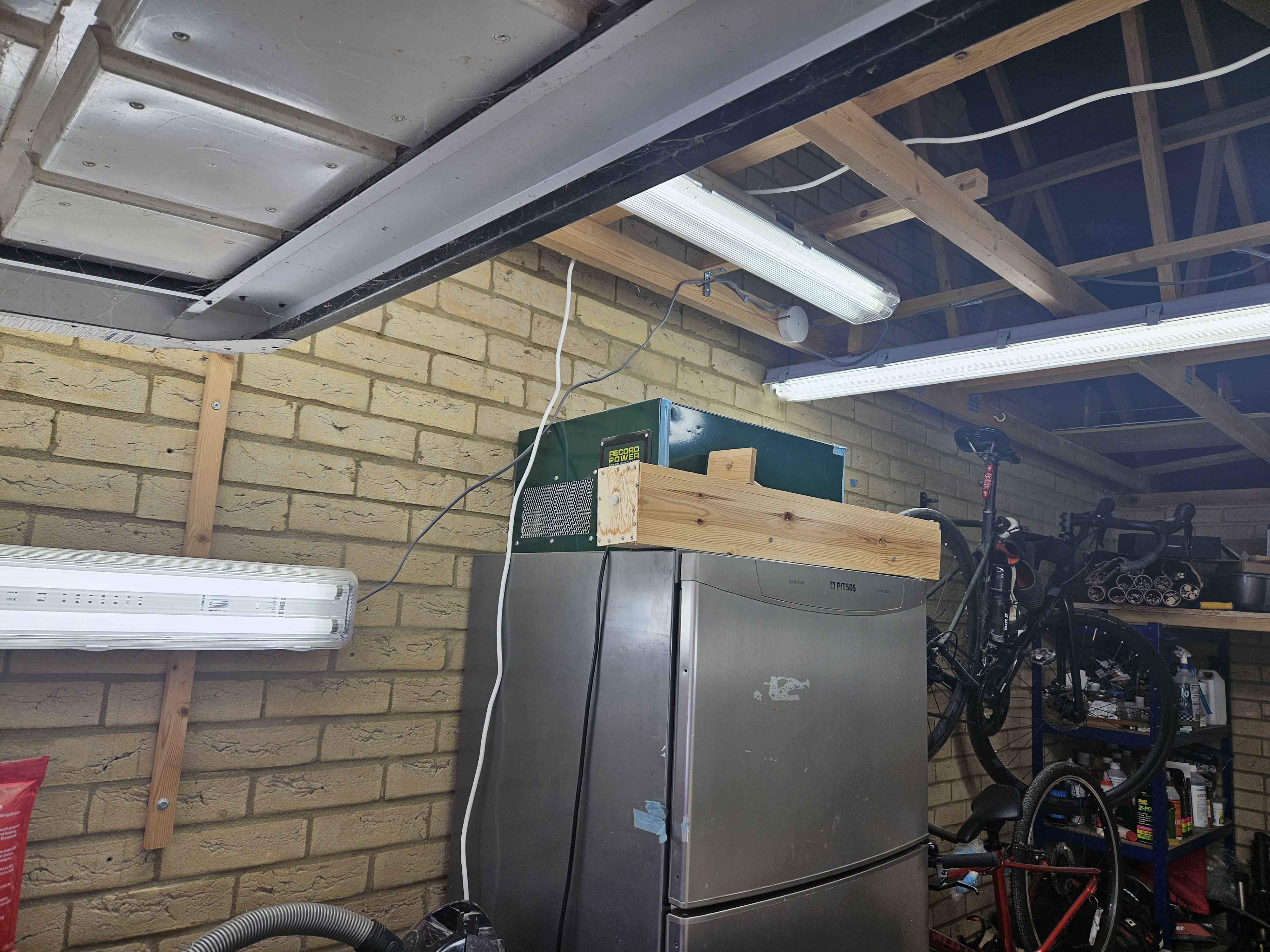
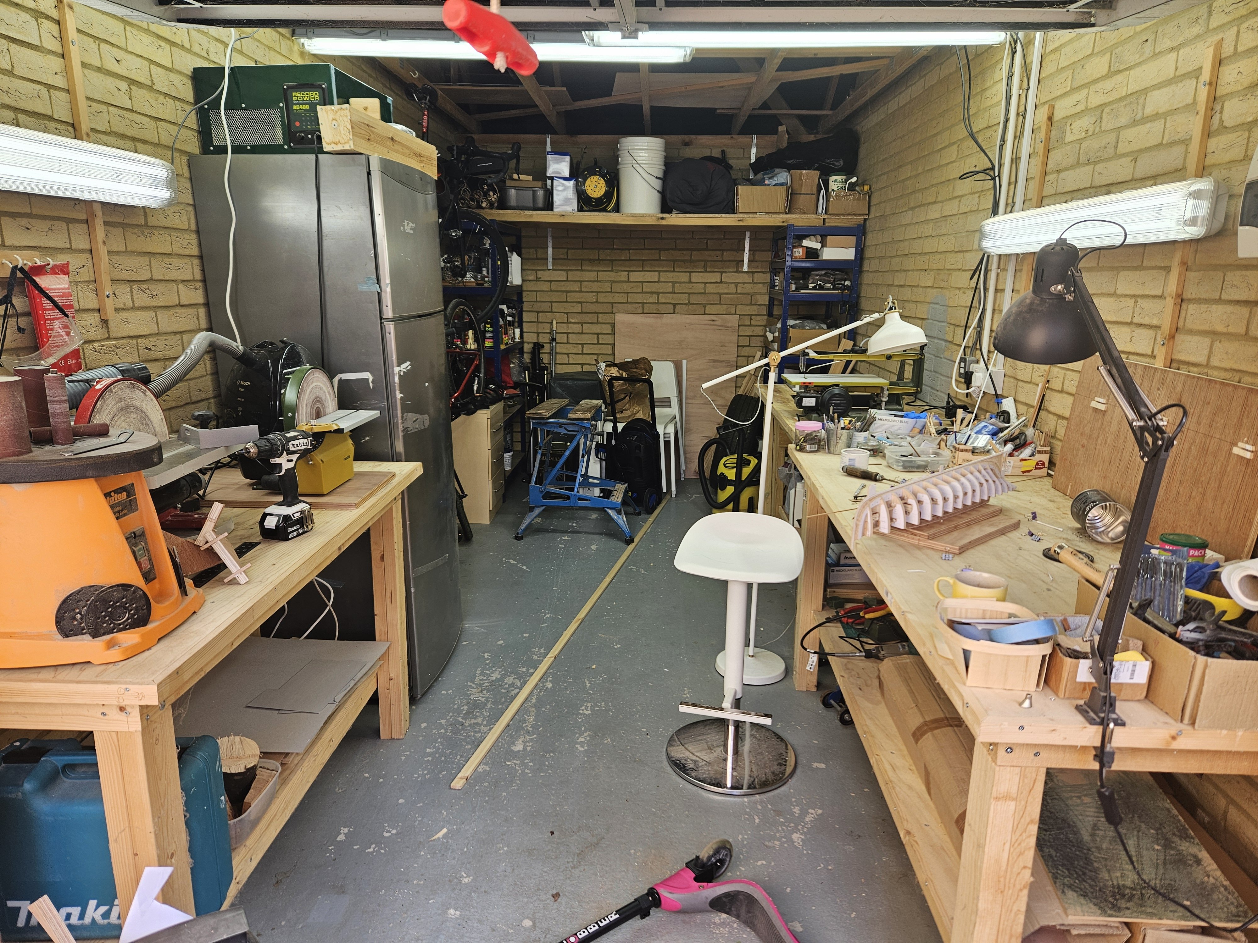
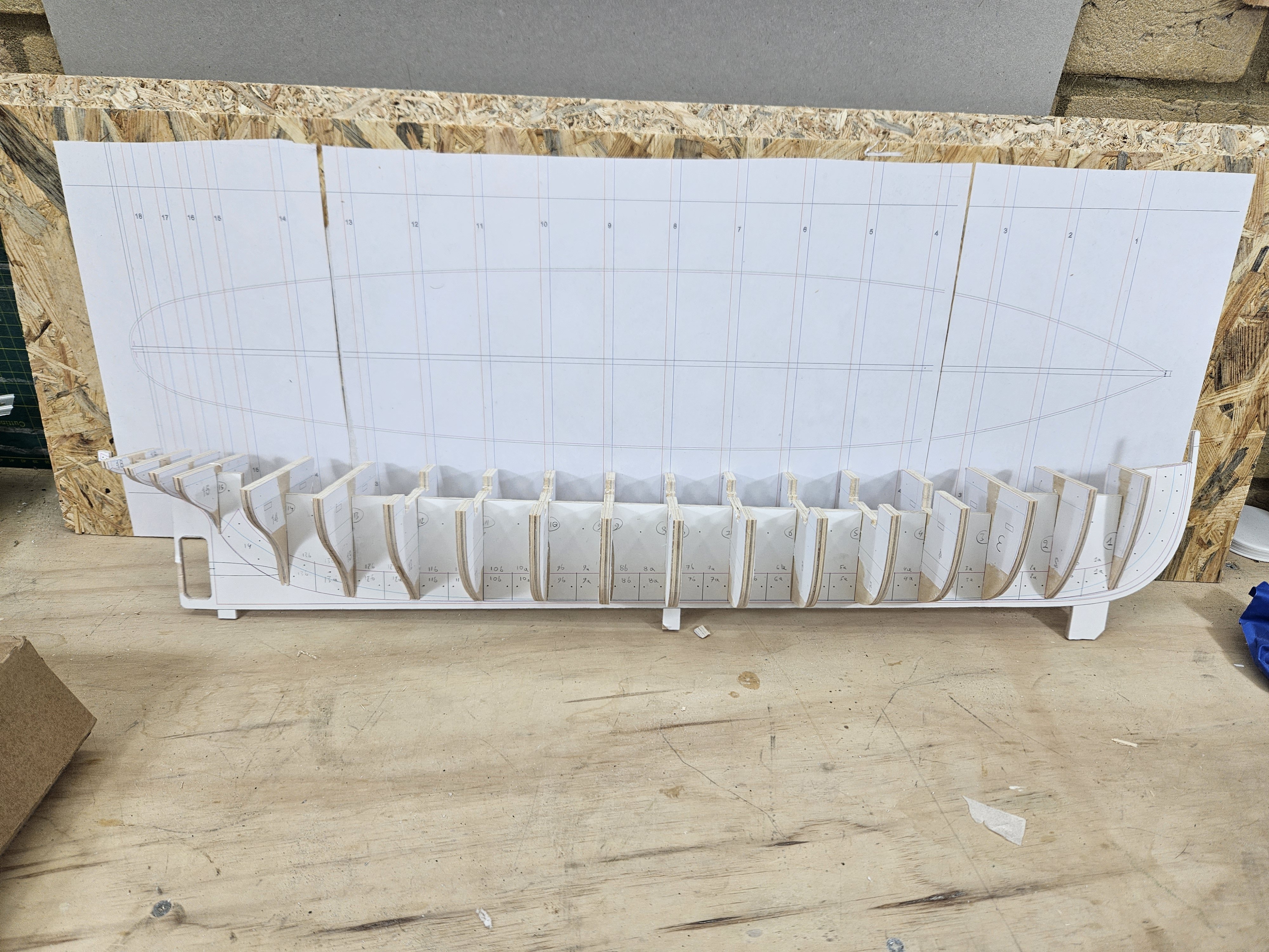
Dear friends Sadly, I have not been able to post for three months - life with its ups and downs got in the way. But I kept on working in the shipyard. Now, this is my first POB model so I am figuring things out as I go. I made a simple jig to hold the keel straight and secure and some plywood right angle pieces. I did a lot of work trying to figure out a way to make sure the frames are square to the keel and installing pieces of wood to provide reinforcements and to connect all frames together. The keel was decidedly bent, it is the first time my epoxy laminates fail to produce a dead straight sheet. Brute force and a heat gun improved the situation a lot. Now at this time, I had to stop and deal with my benches, tools and garage. I was running out of space, too many tools squashed close together in a very full garage. Also, the Axminster disc sander I was so excited about proved garbage, not pleased with their customer support either. So, I made a new bench with the table saw built in. This took a lot of work (I do not have a mitre saw) and a lot of headscratcing too figure out how it would work but I am very pleased with the outcome. It is a very heavy solid bench. Then I took everything out of the garage, threw away lots of things, moved some light fittings, made a kind of loft and put everything back in. Huge amount of work but I am pleased with the outcome. Drilling and cutting bench and main work bench Sanding station. Yes, I had to buy the Proxon disc sander which is very nice I must say. The Axminster one is only good to rough sand the timber to make the bench. This fridge-freezer is taking up space but is also a nice place to put the air filtration system. Can be used for beer as well. Ok, so back to the boat. All frames were carefully installed and secured with thickened epoxy and bits of wood - very solid. The photo shows the hull and a crude base I made to support the hull during planking. This is when I discovered the keel was very bent. The way I designed the boat, the plywood deck had to go in first. This was the first true test of alignment that failed miserably. The deck, printed in an A3 sheet is true and straight and both ends of the hull were pretty off center line - a lot. So, I cut many of the connecting wood pieces, put longer ones in, lots of thickened epoxy and now I have a straight keel - at last! The deck has been installed with screws - this will be replaced with wooden nails but I will also epoxy it in place. In the next photos note the cut pieces and the longer ones glued on top. It does not look pretty but it is solid Ok, so now it is time for planking. I must admit, I do like spilling planks! Now, I intended to use plywood for the planking but this is not going to work, plywood is very unpleasant to work with and does not cut cleanly (it can but needs specialised blades) I do not really want to but new timber, so I looked at what 1.5 mm sheets I have. Left to right is maple. mahogany and pear. Now they are all great but the mahogany is simply too beautiful to use for a hull that will be painted. I think I ll use the maple to start with and if I run out of wood, use the pear. So now it is time to line up the hull for planking! There are some areas that need some consideration, the sheer plank, the top of the stern etc but more on this later. For now, It looked easier to just divide the hull in two sections. I first installed a very wide strip so it would sit dead straight at roughly the turn of the bilge and arranged it so that it would start at the middle of the bow and end aft at the point where the stern rabbet starts turning to horizontal So at this level, a plank would be dead straight. All planks bellow will curve one way, all planks above will curve the other way. I will plank the stern separately from the rest of the hull. Of course I had to reposition this line, then divided all frames (except for the 3 aft and 3 fore ones) bellow this level in 6 sections, put some battens (pear 2x3 mm) and drew the plank runs. Then of course I had to erase all marks, restart and produce slightly better lines. And then do it again. End result with all frames marked: Ideally I think a stealer would be needed aft but I am not going to be too pedantic. So lets make one of the garboards. 1 mm card used to make the patterns in sections - fitted and glued together. A very long garboard, and strangely very straight - I expected more curve I hope this is an accurate pattern. Now, ordinarily I would make this a single long plank but to minimise wood wastage, I am tempted to make it into three sections scarfed together. I also need to think what I will use to cut the planks - scroll saw and sanders or a sharp knife. we will see. On a final note, I was surprised to see that the printed patterns do not seem to fit as well together. I am not sure why but I cannot remember well the CAD designs as I last worked on them in January - I am sure it will work out though. I am also not too happy with my frame alignment - lots of fairing is needed but I may do it as I go along. Till next time Vaddoc


-
Walnut is really not good for modelling due to interlocking grain - it tears and snaps unpredictably.
-
Dear all I thought it is a good time for a short post, mainly one of frustration. Hercules true to the name is fighting me every step of the way and so far, is winning. I ve had difficulties with lofting, difficulties printing the patterns, difficulties gluing them. My laminates that usually come dead straight are bent. My computer died and now, my disk sander started playing up and is in for repair under warranty. But there is more. The new paper template came out in wrinkles. I suspect the spray glue I ve been using has gone bad as all the paper templates I ve glued so far are also coming off very easily. Strangely, the main pattern it is also off by a millimetre or so. The keel does not fully match the pattern - I really cannot figure out why. But there has been some progress despite the difficulties. After a lot of sanding and lots of scraping to remove the paper patterns and the glue residue, the frames are dry fitted. I started gluing the filler pieces, at this stage I will also cut the rabet. I do need to tidy up a bit but it is far too cold. Lots of things to do: cut the rabet, align the frames, epoxy them in place, glue the strengthening pieces and very importantly the planking. I thought I would get away with it by using flat sheets of plywood but I am not so sure now. I think it will need to be a proper planking job. I am not entirely sure how things will work out in the end but it is a fun project! Best wishes Vaddoc


-
Phil, I have no doubt you are right. It will all be hidden and there is nothing that a bit of sanding and a bit of filler cannot correct. And indeed, a small piece of plank material is enough to just find the shape of the rabbet at that frame. I went through your log and of course your hull came out fine. Apologies, just going a bit overboard with CAD! Not to worry though, things will soon revert to normality and will start going pear shaped the moment I touch the ply with a chisel! Vaddoc
-
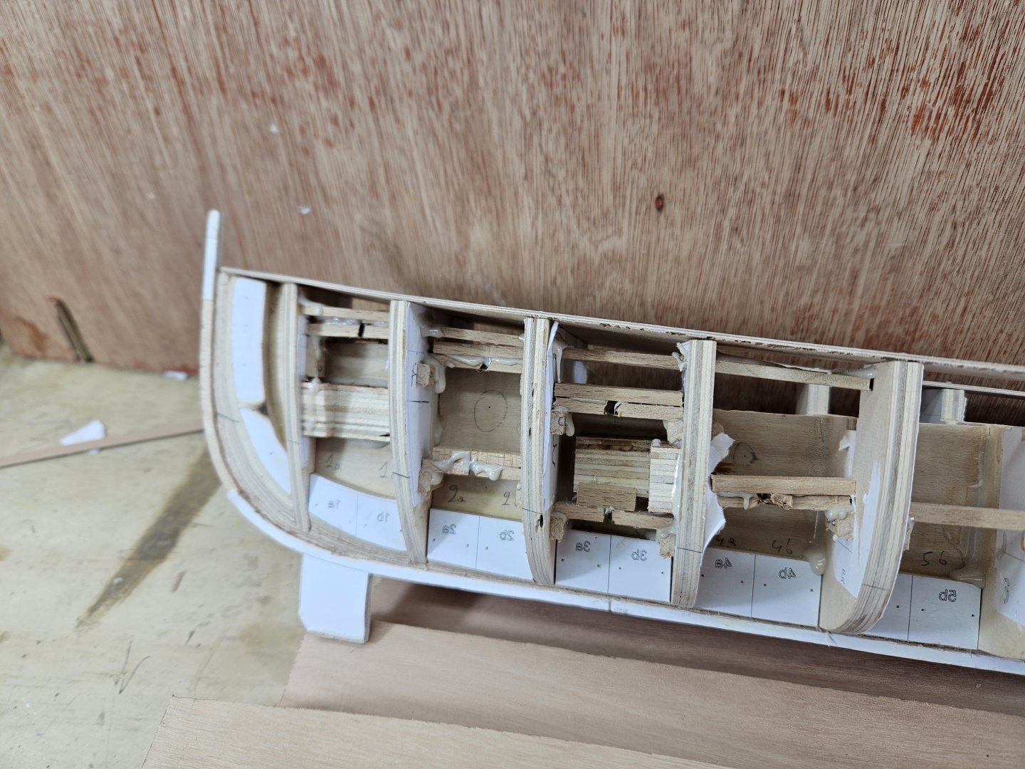
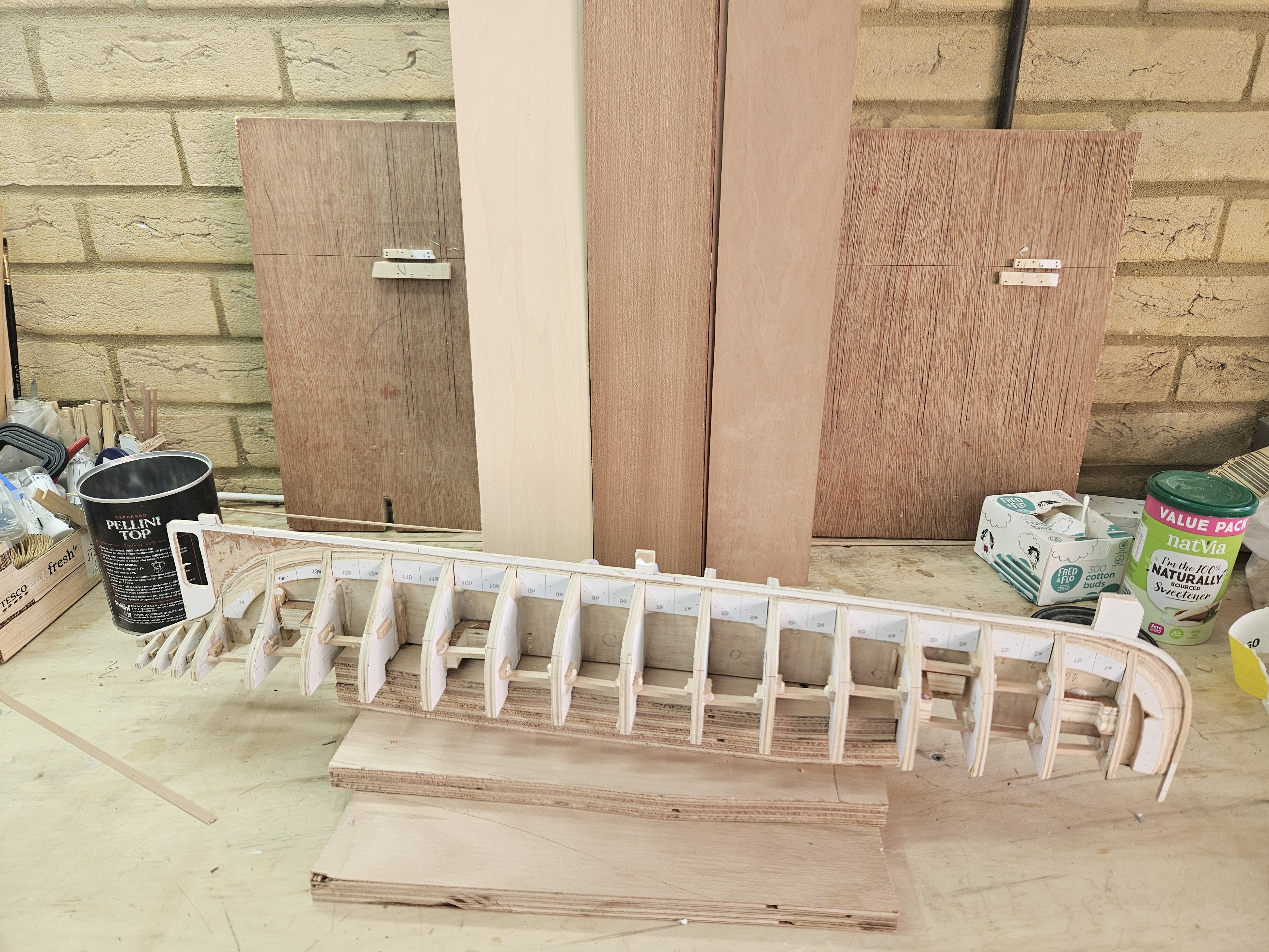
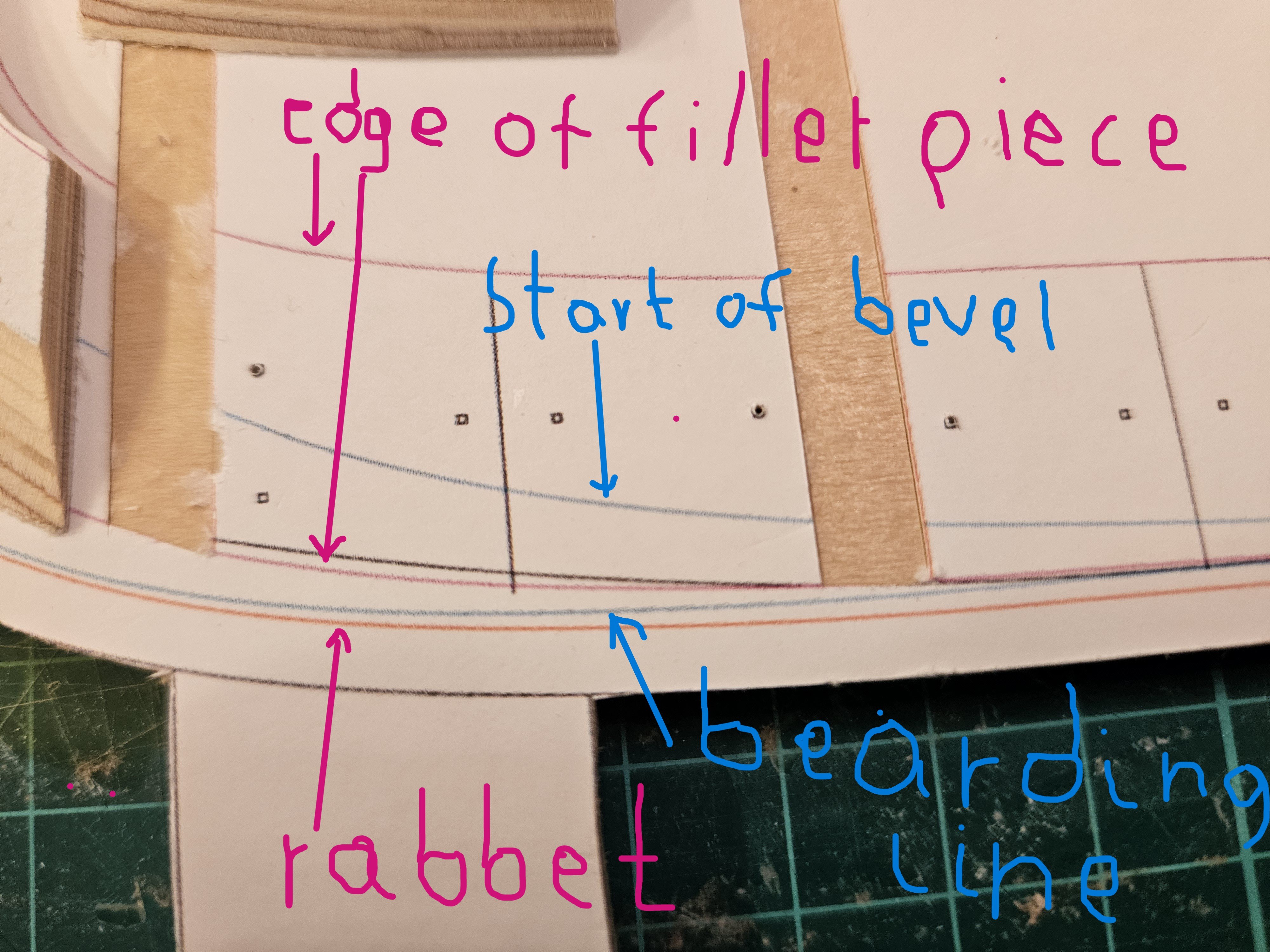
I did a bit more work on the boat, so time for an update. @Mark Pearse Indeed Mark, I wanted to build something much larger and more of a proper ship. I actually looked into building Ed's Young America POF, but this would be an extremely expensive project which at this time cannot be considered. I bumped onto Hercules and immediately liked the boat - rest is history! (in the making) So, I cut the space for the propeller and removed some of the paper template so that the frames can slide into place - they do not actually, all the frame slots need filling as they are not wide enough. I also cut all the filler pieces for both sides and sanded all their bevels. These are needed to give support to the garboard planks as I will not be filling the gaps between the frames with wood. This went remarkably well, although some of the bevels had complex shapes. I only had to redo 3 out of the 30 pieces. This is a piece that had to be redone, the disk sander is not forgiving. I also sanded all the bevels in the frames. It went well but some fairing will be needed for the frames at the middle of the hull. These are all the pieces that need to be glued. This will need a lot of work: the paper template will need to be removed and the surface sanded or scraped to remove the glue residue and the pieces temporarily screwed in to check that the frames can slide between them. I think I ll use epoxy, it is a messy glue but has great gap filling properties. The elegant curves of the hull and frames, or alternatively Hercules after a dose of Delayed Mouse Making Potion. I am assuming that my CAD plans are accurate and that I ve cut the wood accurately. Of course neither is certain. The bevels seem reasonable though. I will need to cut the rabbet before I install the frames. I will first though glue on the filler pieces, as the angle of their bevel will help cutting the hull bevel. In theory, I have all I need to cut the rabbet accurately as all lines and the interaction of the planking with the hull are marked on the templates. However, chiseling plywood is difficult and requires extra sharp chisels. Take care all Vaddoc


-
This is a very nice 1:1 model Bedford! I like the exaggerated sheer at the bow - it should handle rough seas (and lakes) well! Now, you are very right. This is the way to do it. The problem is that it is very difficult to escape the urge to closely follow the CAD plans with their scary accuracy - I have the illusion the end result will be as sharp as the plans! I ve been watching the Tally Ho videos - incredible what these guys do without using CAD, just with battens and pencils! The hull is very long and not dead straight. The frames will be pre-beveled before installation and even small deviations from vertical will cause problems - I know, they can be sanded or shimed. In the end it will end up with a batten around the hull but I assume the more fussy (or pedantic) I am with accuracy and alignment of the hull and frames, the less intervention will be needed later. This is my first POB boat and plywood responds very differently to solid wood. Having said that, it might very well not work - in all my previous boats in the end I ended up eyeballing the fairness of the hull! Vaddoc
-
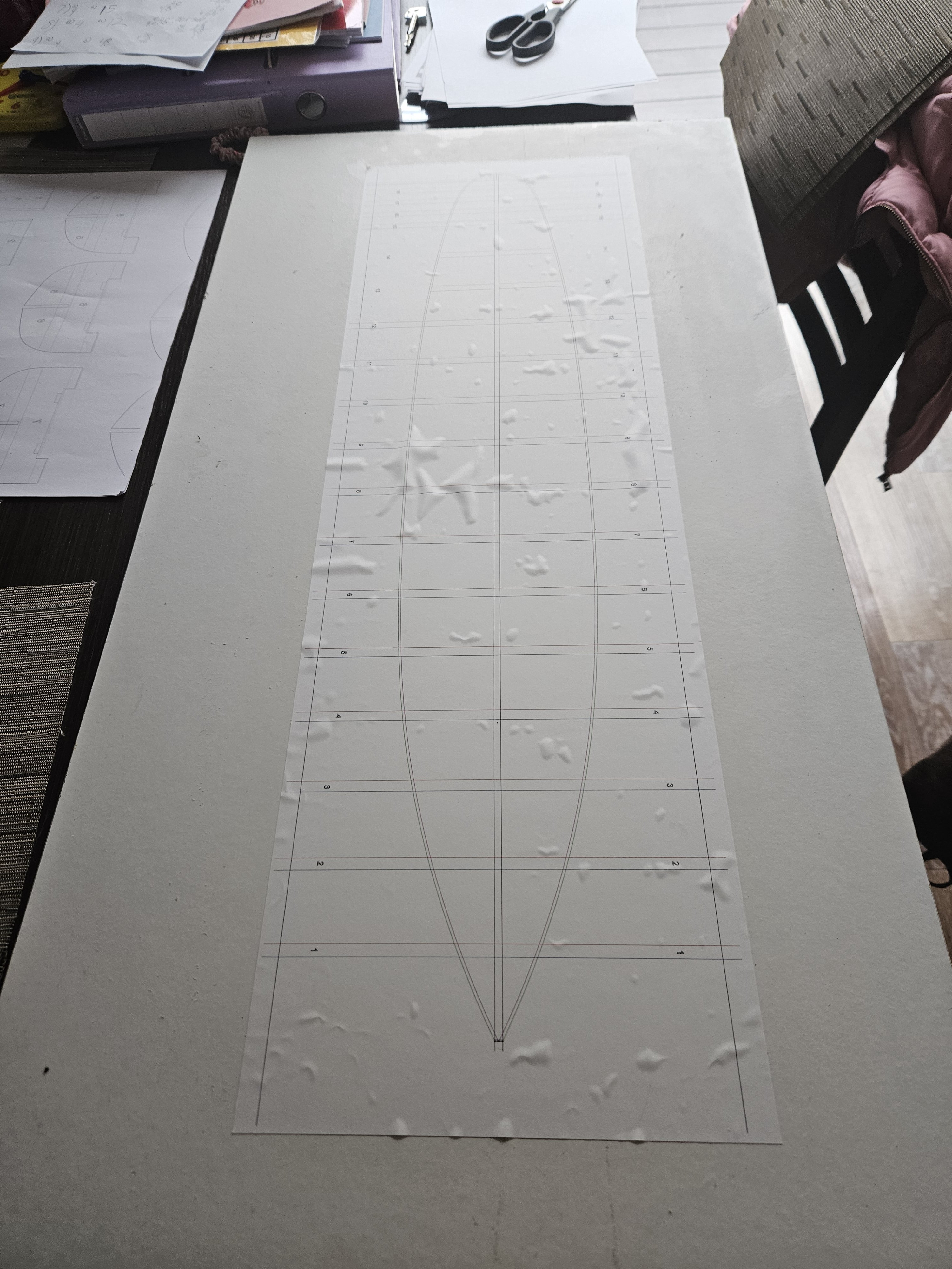
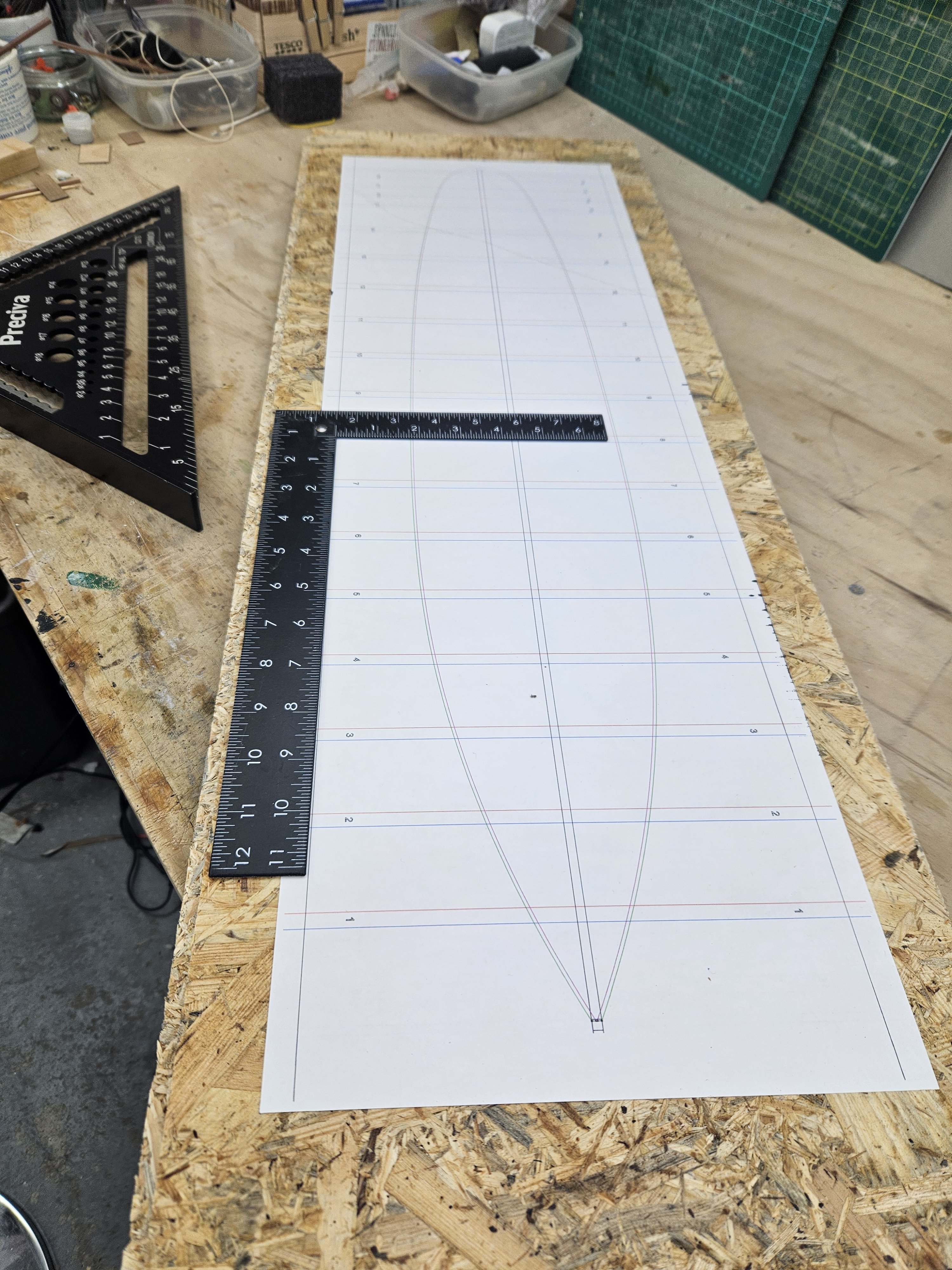
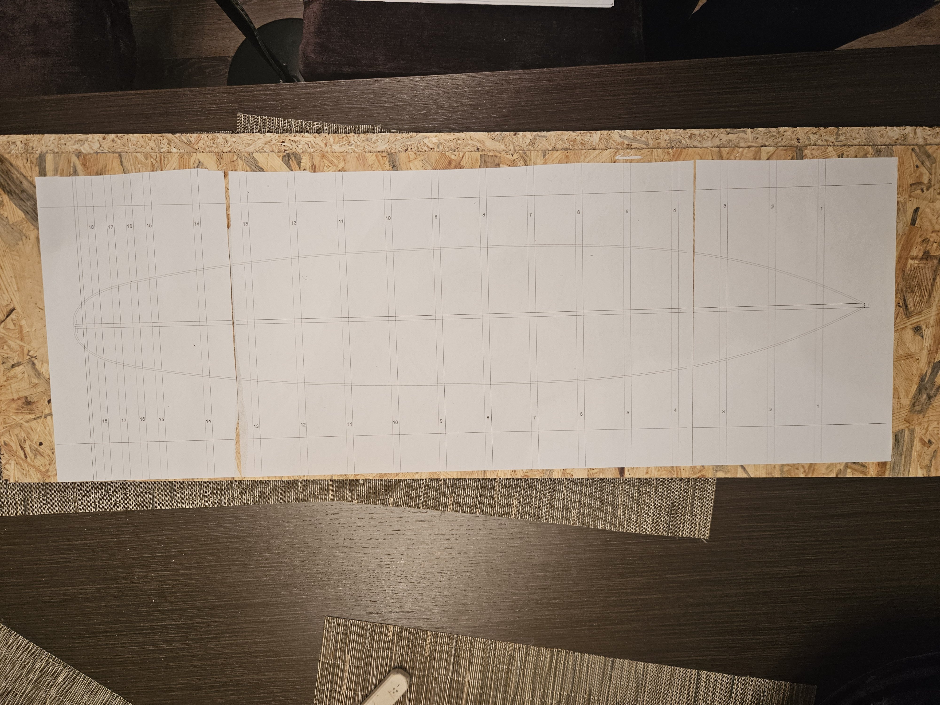
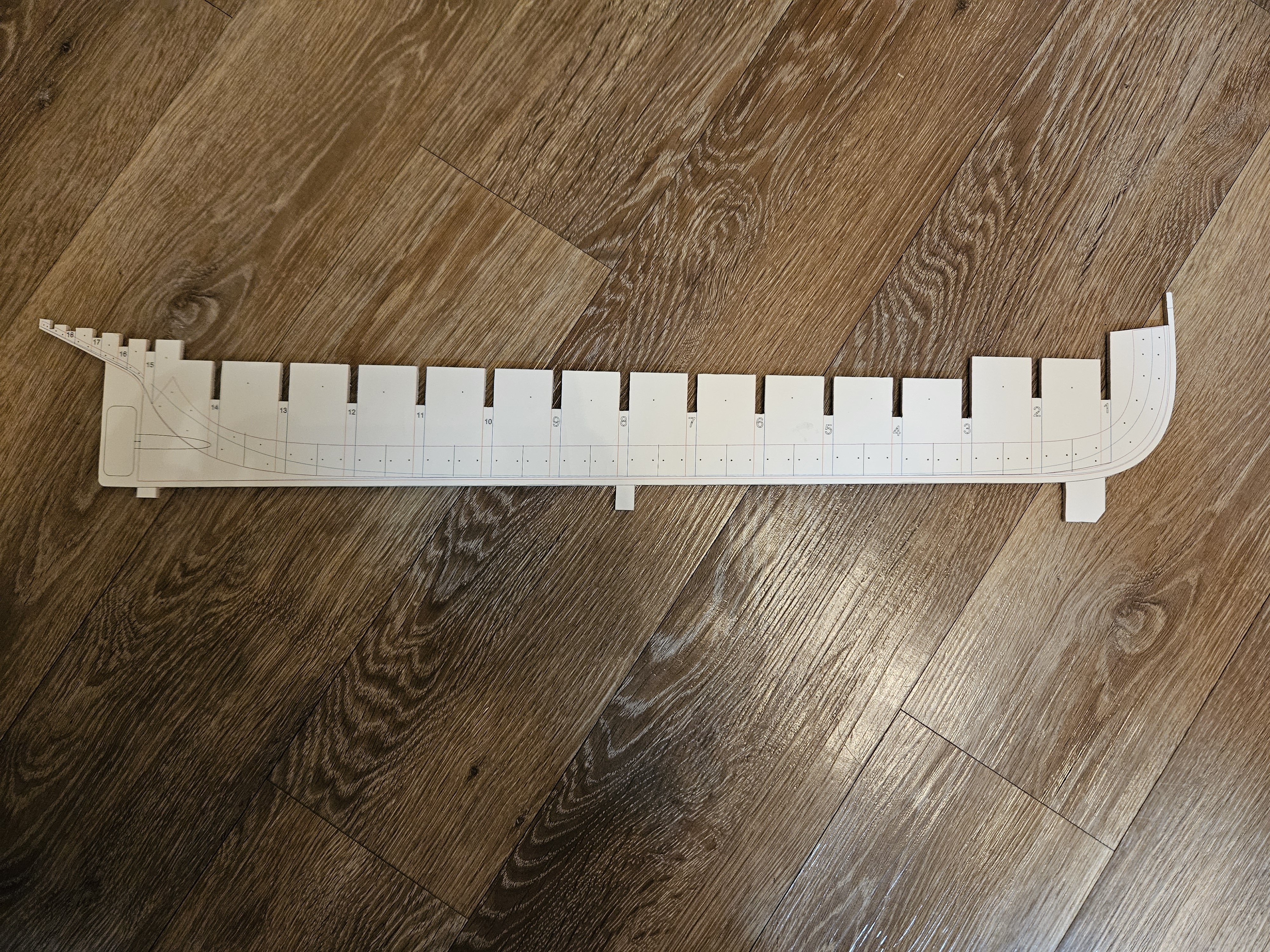
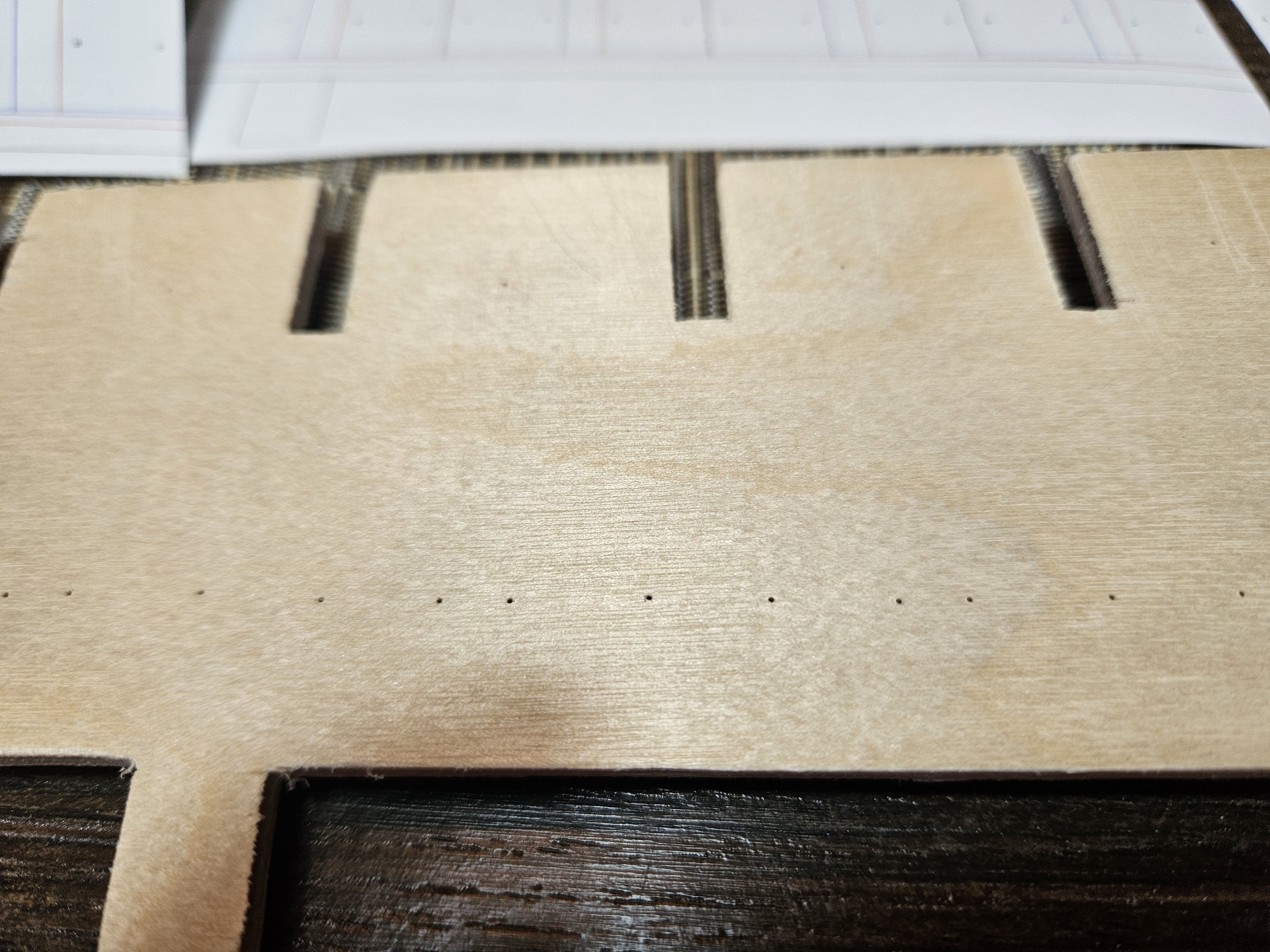
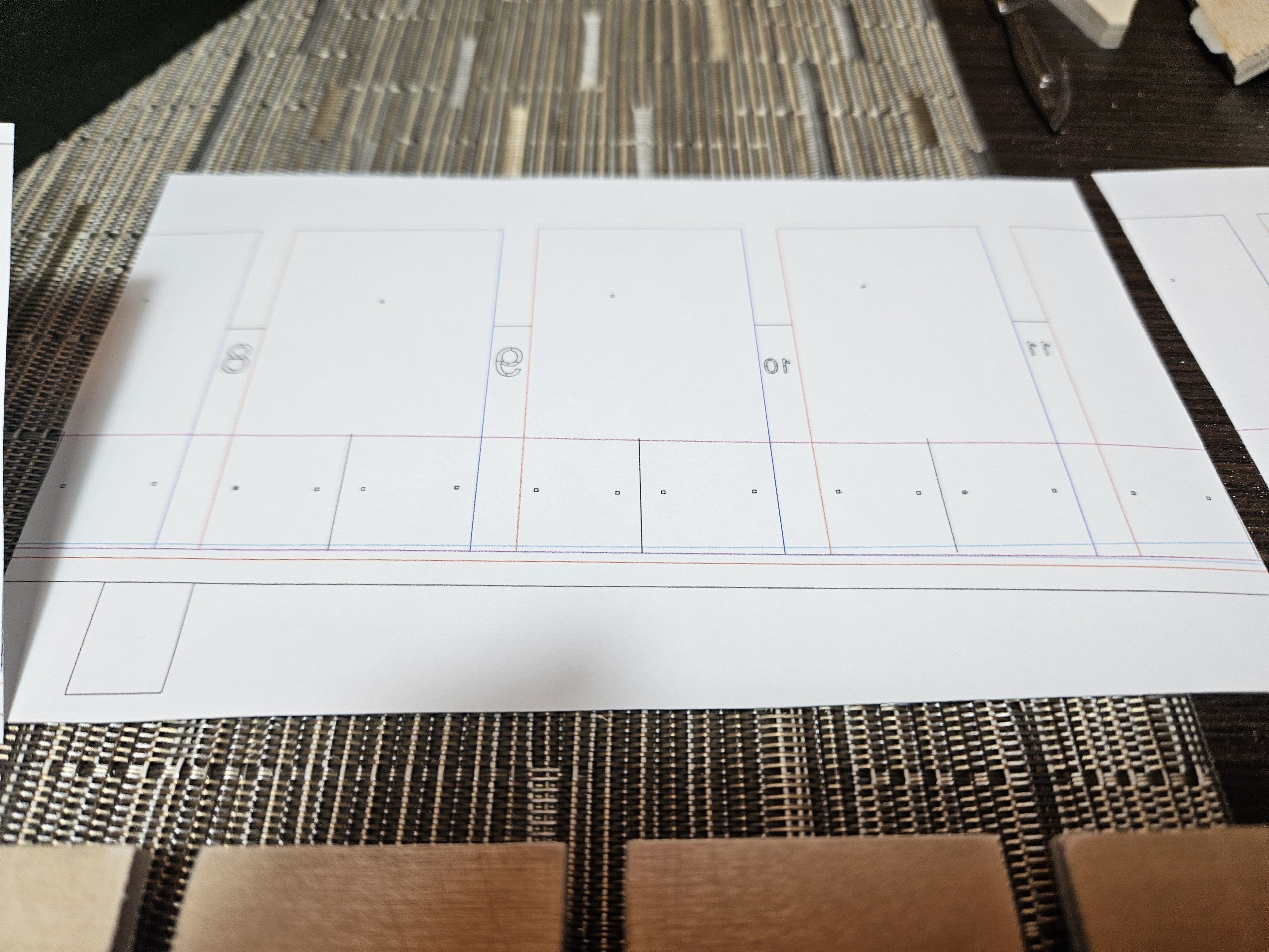
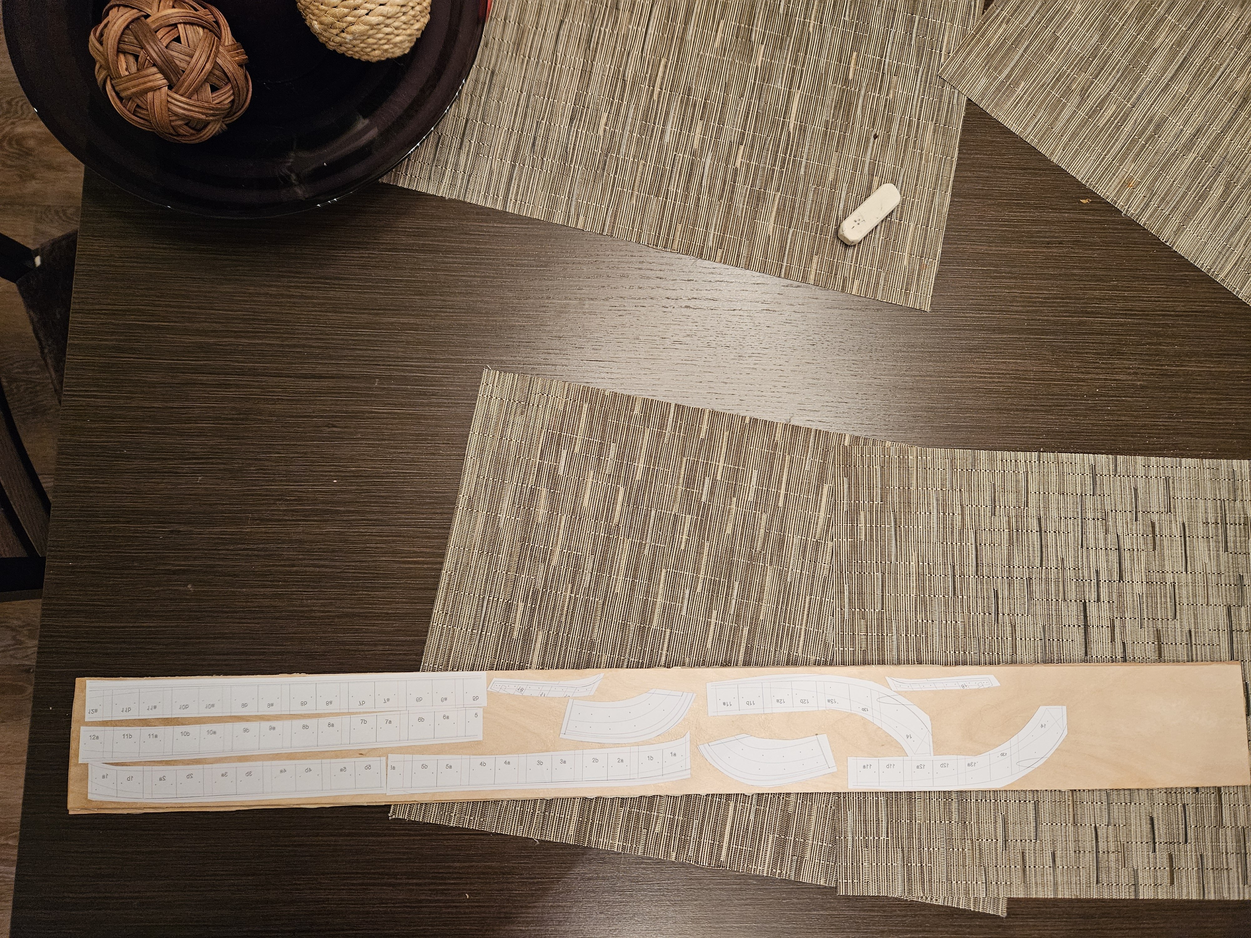
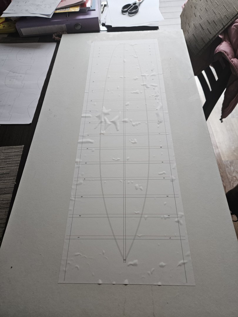
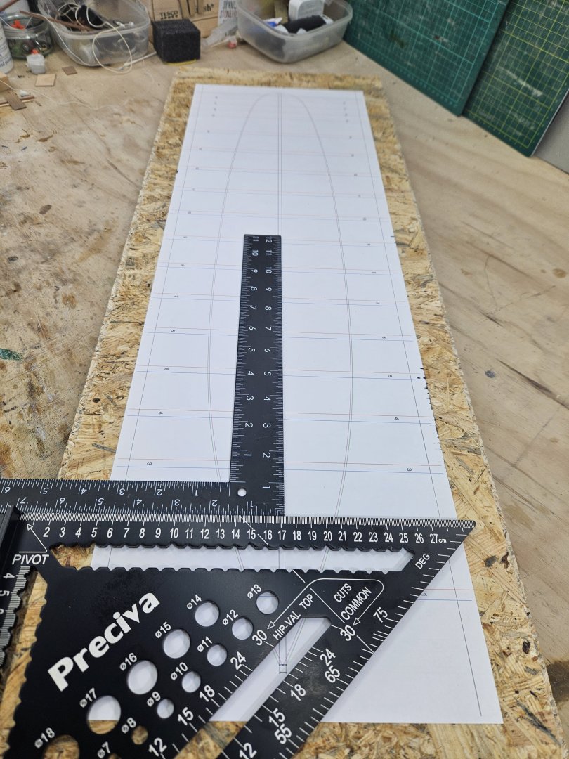
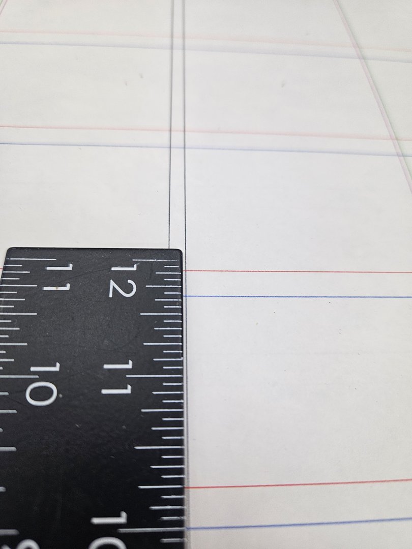
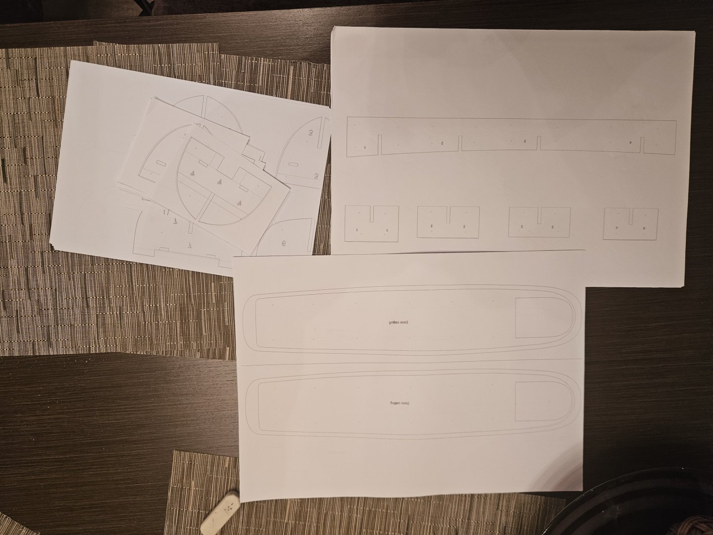
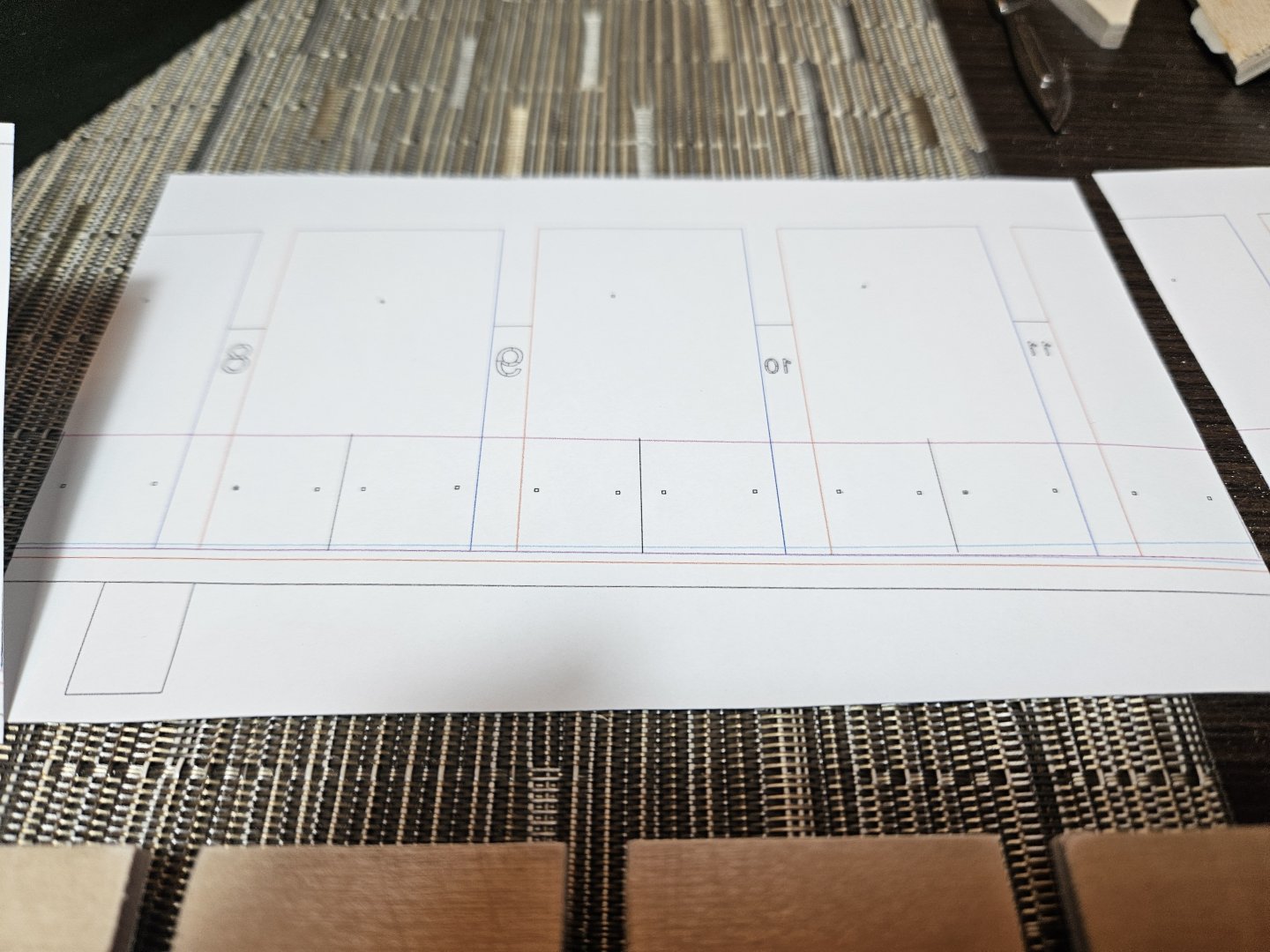
Happy New Year to all! I ve been busy these last few weeks so time for an update. Quite a few things going on. I could have actually done more but the temperatures have been consistently subzero so my garage is a rather unhospitable place to be in. So, I have finished laminating the pieces of ply I need but things took a funny turn. The laminated ply that was dead straight, warped. This is the first time this has happened to me. Still, with manual bending the opposite side and heat from a hair dryer, it went back to being almost straight. Now, I need a new bench for the garage. I already have two but my power tools are very cramped and it is difficult to work. For the new bench to fit I had to radically reorganize the layout of the garage - I am halfway into this. The new bench will have the table saw built in to sit flush with the top. I tried to design it by hand but finally returned to the warm embrace of CAD! These are the various groups of timber bits A big advantage of CAD is that it is very easy to arrange how many lengths of timber are needed and which pieces will be cut from each one When the weather allows, I ll get down on this. Now, back to the boat. I glued the template on a flat surface and after lots of thought a sprayed it with a protective spray. Ya, right. That did not work. I printed the pattern again and glued it on a different surface. I used custom settings and long lengths of paper cut from an A2 roll. However, the printer could not align the paper properly and the printout was distorted So I printed the pattern in A3 sheets and aligned them carefully. This actually worked fine, I used a piece of string and all lines are straight. I also did a lot of work to finalise the frames and other parts of the ship. We ll get to these later in the log. I glued and roughly cut the templates for the frames. There are many dots and lines for alignment purposes. I ll sand them to the lines with the disc sander when the weather improves a bit so I can have the garage door open for the dust to vent away - however sanding of all the bevels will take a long time. I finished cutting the keel template which again has many points and lines to allow alignment - each has been drilled through in the drill press with 0.55 mm drill to allow a 0.5 mm pin to go through. The mirror template has been glued on the other side - quite successfully. I have also prepared some extra pieces to glue on the keel to allow some more area to support the planking. These will also help in the alignment and support of the frames. All the bevels are already marked. I have ordered some different blades as I am not satisfied with the performance of the Proxxon scroll saw - but then again it comes with a very fine blade which struggles to cut the 6.5 mm epoxy laminated ply. So next steps: To cut, sand their bevels and glue the extra pieces on the hull. To sand the frames including the bevels. I think I will cut the hull rabbet now before even the frames go on - I have marked all the rabbet and bearding lines. One thing I could have done differently is the thickness of the hull. In my plans the hull is 3.8 mm thick - I did not want to make it thicker as in the plans, Hercules' steel hull is very slim. However, in the bow and stern, the rabbet will need to be up to 1.5 mm deep on each side so not much hull thickness left. I still am undecided on the planking. I think using large pieces of plywood will not allow a fair hull. I may need to plank the hull the usual way. I d like to cut the planks from plywood sheet but plywood does not cut very cleanly on the scroll saw- there are various other blades though. I could however use wood for the planks or a hybrid approach - use ply at the bow and the stern and wood in between. We will see. Till next time Vaddoc
.thumb.png.96c0001f0ed12641cc6f986d6f03f25a.png)
.thumb.png.35672fc3d8bdb29c187228ccaabfb658.png)
.thumb.png.9437585cc03117ce8f33d3f3ebac4701.png)


-
Very nice shipyard Hakan and the boat is coming along fine - very elegant. Love the beefy frames! Great news health wise mate! I looked for "out-of-place items" but the only odd things I could identify was the bike and the old oil lamp hanging from the ceiling. Take care Vaddoc
-
Many thanks to all for your kind words! @Wintergreen I was hoping nobody would notice Hakan! Indeed my calculations were wildly wrong and a bit too late to correct - I had no more brass left and all were too firmly glued with CA. Not to worry though, Hercules will have a massive propeller which I can always make it a bit larger so between the two boats it averages out fine!


.png.bd4de358119daebfb6cb749d180760f3.png)
.png.8b5efde90fd570adcb382cebe64b958e.png)
.png.ce125d5f0f89264c5b5e79c94143934c.png)