.jpg.f26acc9a74319261612561bfa7da1303.jpg)
vaddoc
-
Posts
1,605 -
Joined
-
Last visited
Content Type
Profiles
Forums
Gallery
Events
Everything posted by vaddoc
-
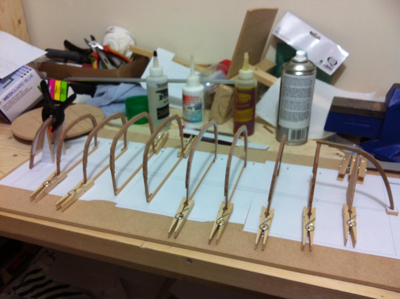
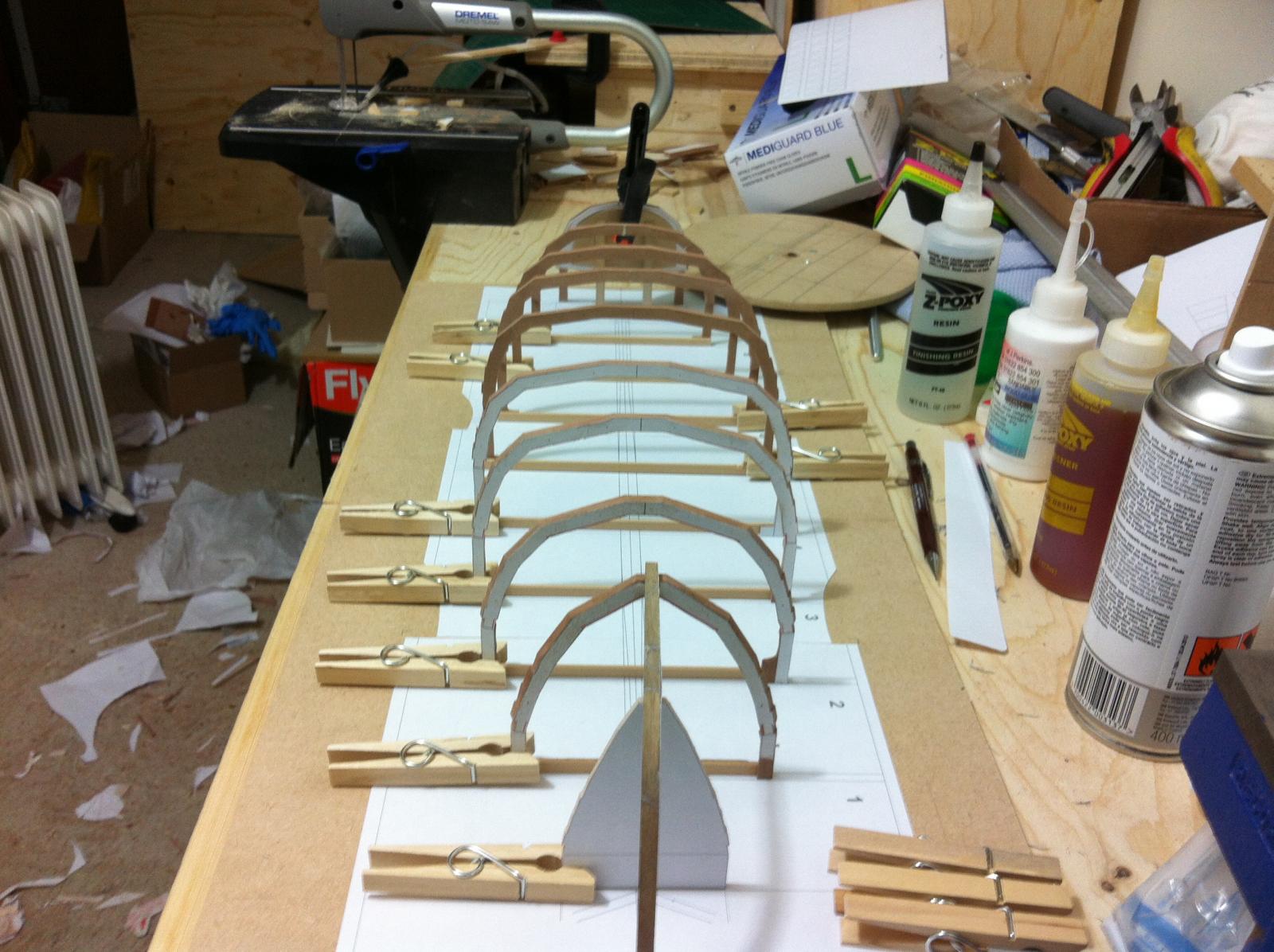
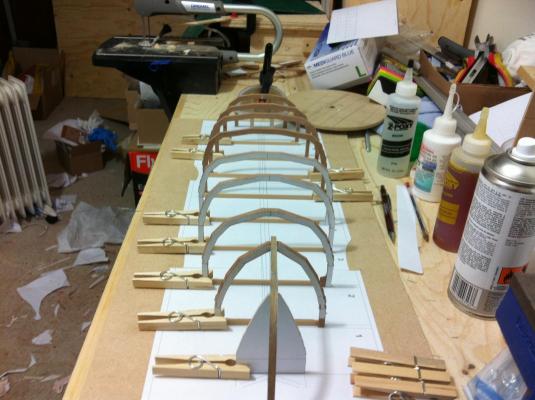
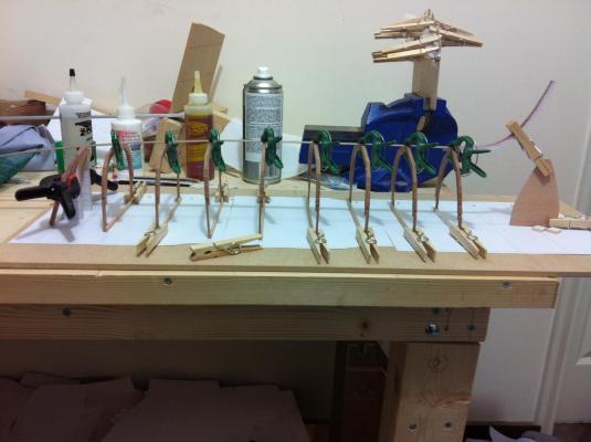
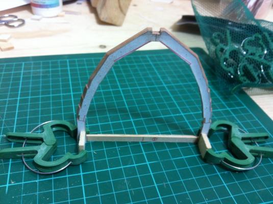
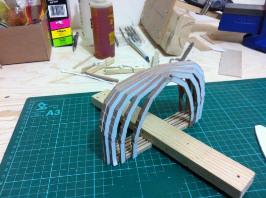
.thumb.jpg.6fd4c1b78768bb3efd745ab810936005.jpg) Thanks Patrick, indeed the new stem is now drying! I've ended up using this jig more than my favourite disc sander. I printed out the pattern to position the frames and i realised that the nice thick piece of MDF i had saved was warped. I used the last piece of the old drafting table and I could not resist arranging the frames and transom. Looks so much better than the first attempt! Of course I had to add a strip to check the bevelling for the apron. It feels pretty near. And of course check the bevelling randomly on the port side... ...and the starboard side. I am a happy man!
Thanks Patrick, indeed the new stem is now drying! I've ended up using this jig more than my favourite disc sander. I printed out the pattern to position the frames and i realised that the nice thick piece of MDF i had saved was warped. I used the last piece of the old drafting table and I could not resist arranging the frames and transom. Looks so much better than the first attempt! Of course I had to add a strip to check the bevelling for the apron. It feels pretty near. And of course check the bevelling randomly on the port side... ...and the starboard side. I am a happy man!


- 253 replies
-
- 6
-

-
- ketkch
- gaff-rigged
- (and 1 more)
-
NIce to have you along Yambo, I know what you mean, I hope things will settle so you can join the frustration of trying to put this thing together! I used mahogany extensively in my previous boat and although I liked the colour I will probably not consider it in the future. It is very strong but sanding and shaping it is difficult. I used mahogany for the deck and then wanted to give it a shiny finish. It is so porous though that It took a dozen coats (or more) of tang oil, shellac, varnish and wax to get some kind of shine. But it is beautiful wood indeed! Today was a bad day. I test fitted the stem and the station 1 frame only to discover that the stem is short. Instead of sanding the stem to the building line I sanded it to the sheer! But of course that was not the only problem. As I was looking at the above picture I realised that I sanded the wrong side of the line at the end joining the frame. The notch should look up to receive the apron ! A pint of beer later I started the process of laminating the stem-for the third time now! The walnut strips sit in the jig now waiting to cool down till tomorrow. Stems were invented by the Devil himself.
- 253 replies
-
- 2
-
-
- ketkch
- gaff-rigged
- (and 1 more)
-
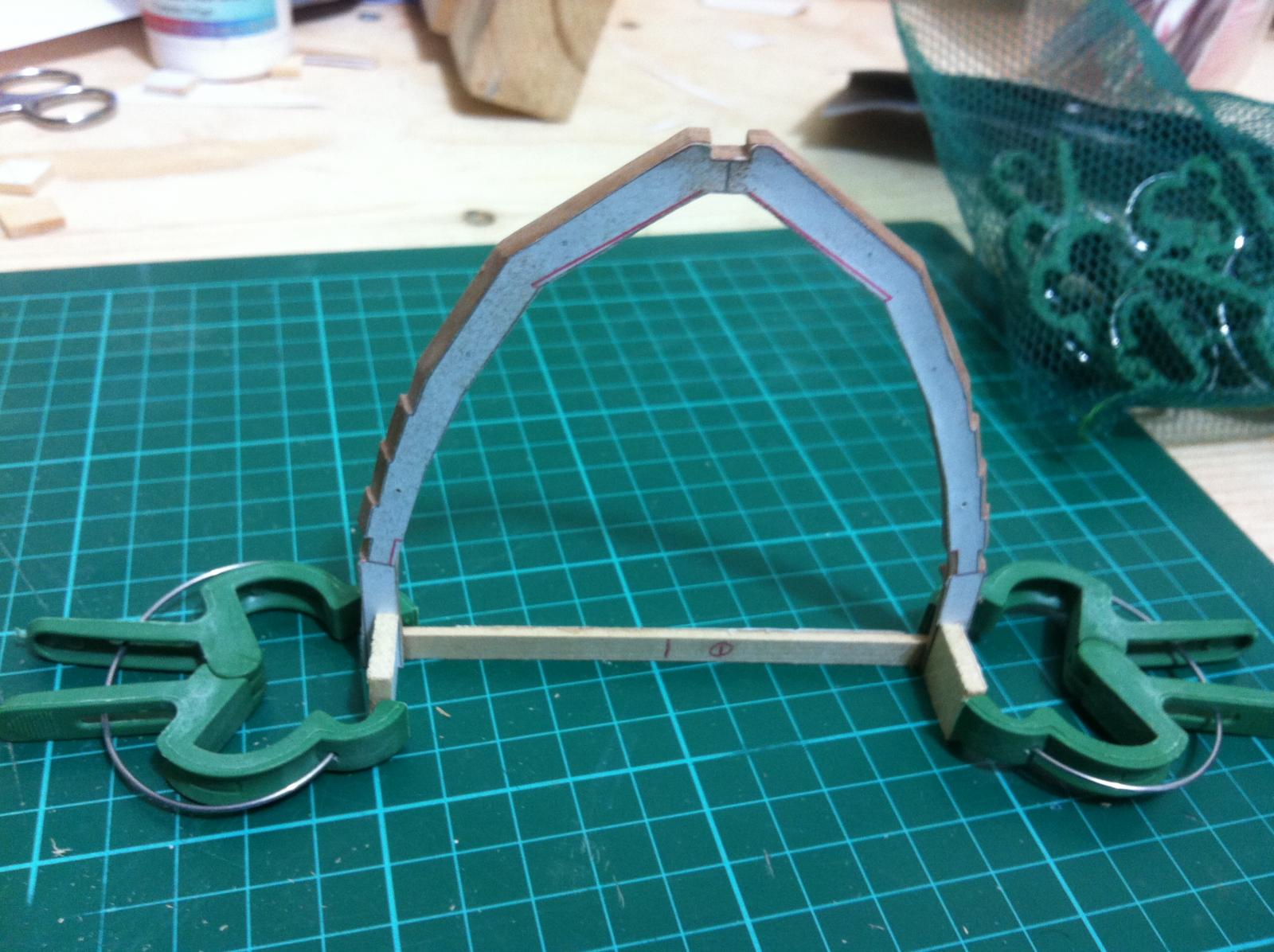
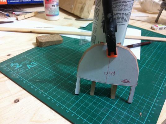
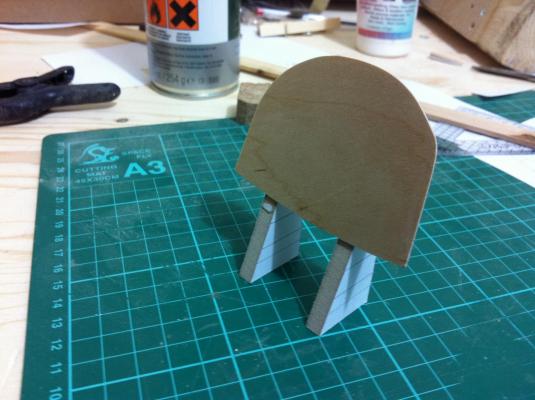
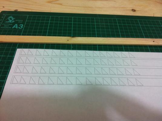
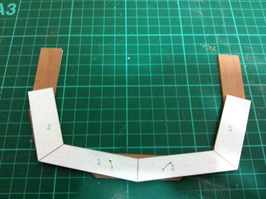
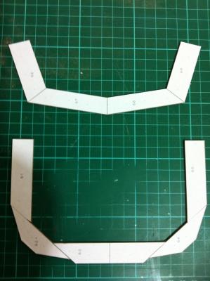
Michael, I will definitely try this before I glue any large pieces. The PVA glue I use is old and has thickened a lot but the warping proves that moisture needs to be balanced. I did some more work on the Transom (this time laminated with epoxy) and also built a cradle to keep it in place. I am sure the angle will be fine, the difficult will be ensuring it is perfectly square to the midline. As for the frames, I cut 90' triangle shapes. I used the wood from a garden support I bought from Poundland, it is actually very dense and strong and sands very nicely. I intend to make sure the frames are vertical and in position and then glue the frames to the shapes and the shapes to the floor. When the Apron and the outer clamp are inserted the boat should be pretty rigid.
- 253 replies
-
- 2
-
-
- ketkch
- gaff-rigged
- (and 1 more)
-
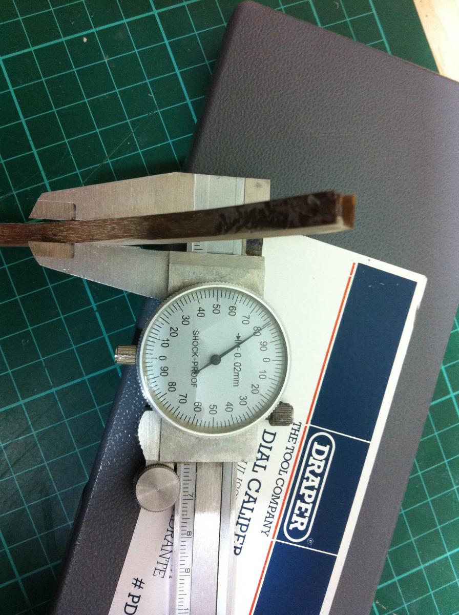
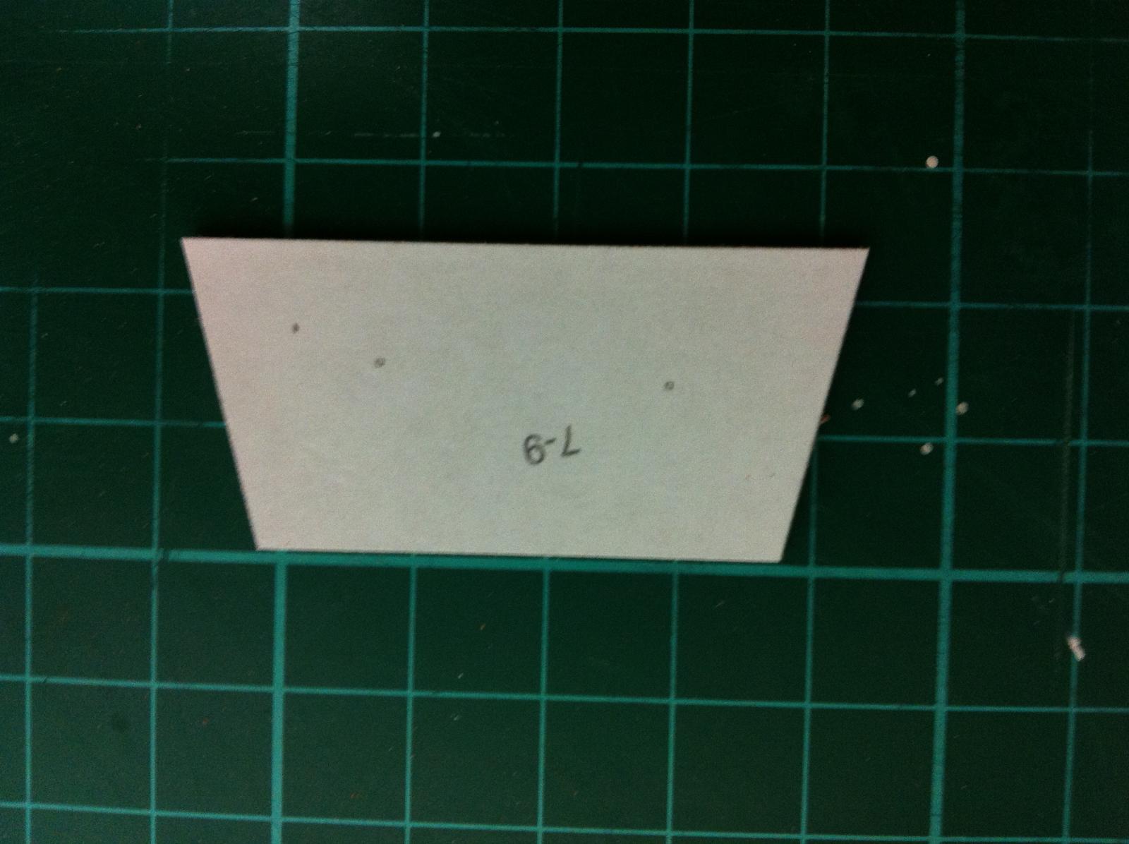
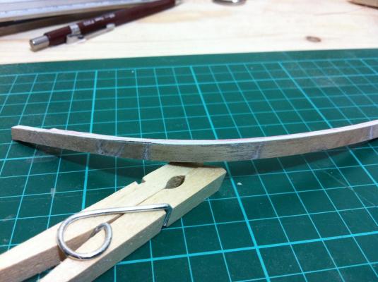
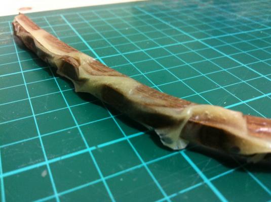
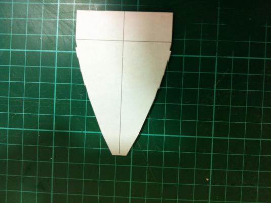
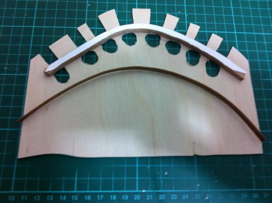
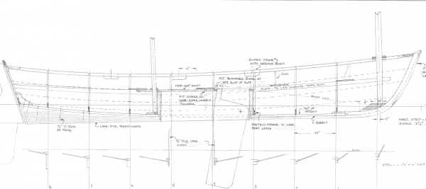
I had very little free time today but I just had to finish the stem. I must say, it took very little time and the job was completed entirely using the homemade disk sander. I used 6 mm strips but in the plans the stem width is 5.3 mm. After sanding the epoxy off the width was 5.8 mm. Although I was only 0.25 mm off on either side I decided to sand a bit more forgetting the old saying "Better is the enemy of good". The result was that I sanded a bit more on the side that meets the No 1 frame reaching 4.9 mm width. No harm done though as although slightly thinner it is symmetrical. The junction of the shaded and non-shaded areas is where the planks join the false stem. Of course due to the tolerances it can only be used as a rough guide. In any case I now have a strong smooth false stem! Next tasks: 1. Transom 2. Jig and setting up of frames 3. Laminate Apron

- 253 replies
-
- 3
-
-
- ketkch
- gaff-rigged
- (and 1 more)
-
This is excellent advise Michael, I wish I had this knowledge at that time! I use aliphatic PVA glue which is not water proof but as I put a lot of glue for laminating, the wood might be unusable. I will soak it though to see how it will respond. For future reference, if wide pieces need to be glued, do you think these should be soaked in water first to saturate evenly and prevent warping?
-
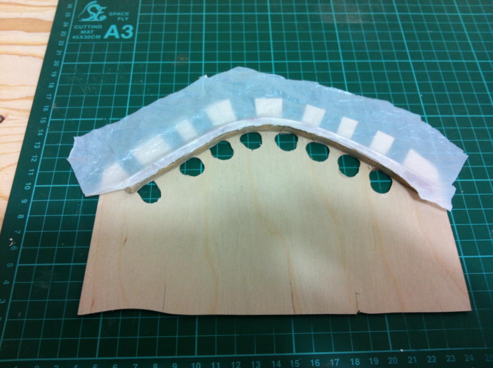
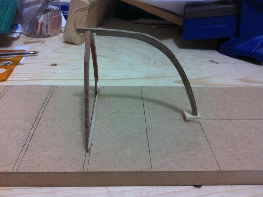
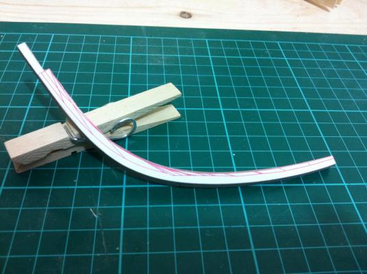
Today I removed the stem from the jig. I t looks very good, no spring back at all and no delamination. I cleaned as much of the epoxy as i could from one side of the face before it cured, but the other was inaccessible. It needs to be sanded off while keeping everything square. This will be challenging.

- 253 replies
-
- 1
-
-
- ketkch
- gaff-rigged
- (and 1 more)
-
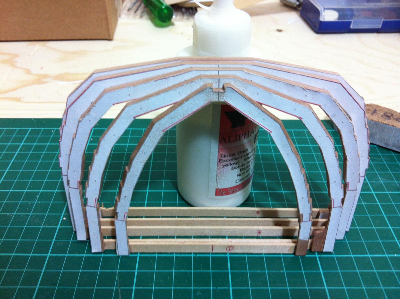
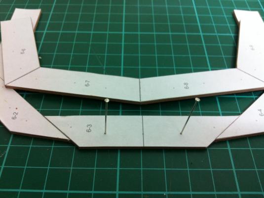
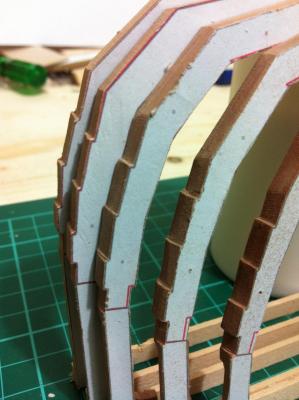
At last all the frames are ready! The notches seem to align reasonably well although I suspect they are not deep enough. There will be two plywood planks in the bottom and lower chine, 1 mm thick and 4 pear planks 1.5 mm thick for the middle and upper chine as well as an inner and outer clamp. This is a strange boat, the lower half of planking will probably need to be constructed with epoxy filleting and the upper half clinker built with rivets.

- 253 replies
-
- 2
-
-
- ketkch
- gaff-rigged
- (and 1 more)
-
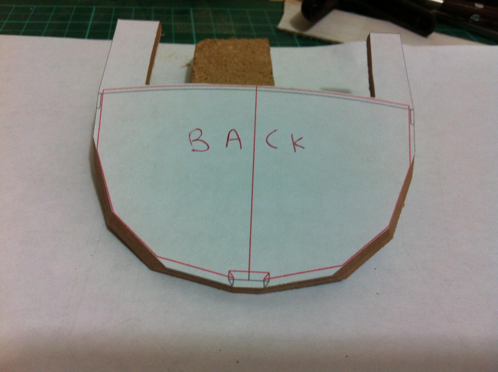
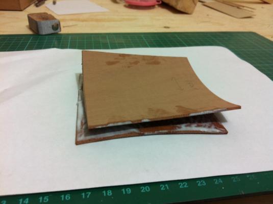
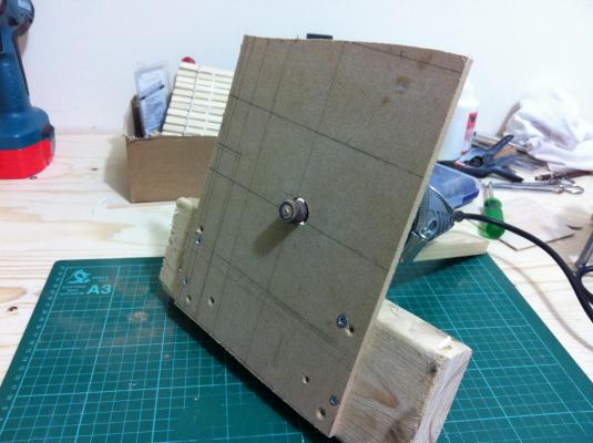
Now something I need to share with you all. I was not entirely happy with the Transom so I decided to start over. The two sheets were pretty much flat but after the PVA glue went on they warped. I have never come across this, I guess the water in the glue caused uneven swelling in the wood. I suspect my wood is very dry.
- 253 replies
-
- 1
-
-
- ketkch
- gaff-rigged
- (and 1 more)
-
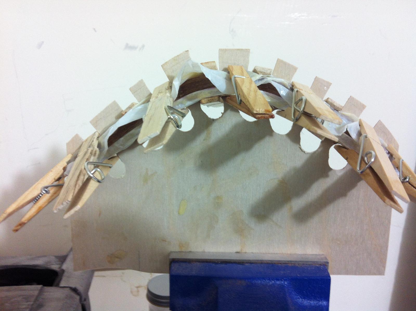
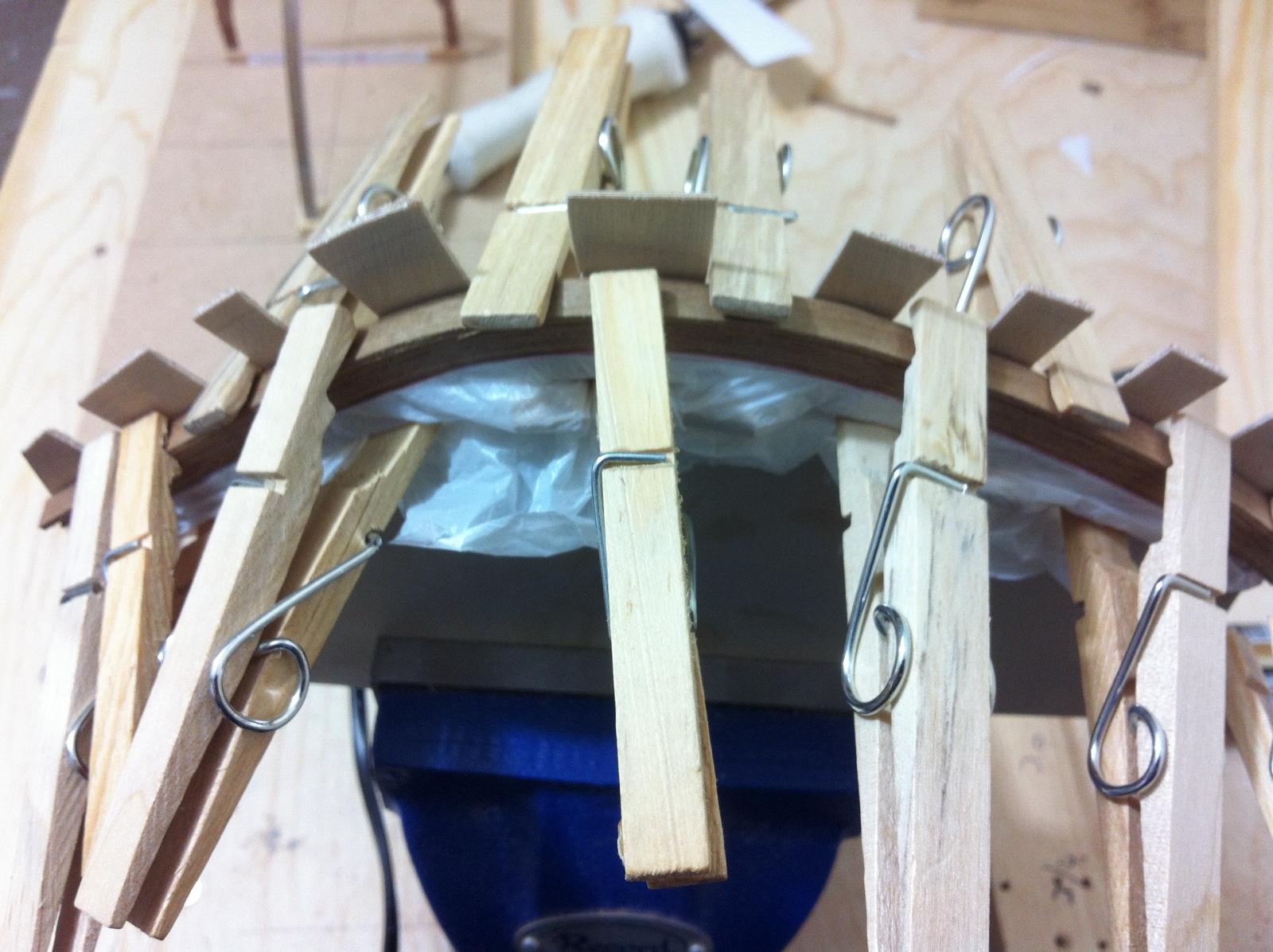
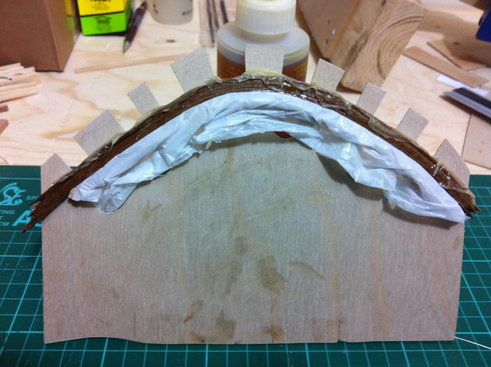
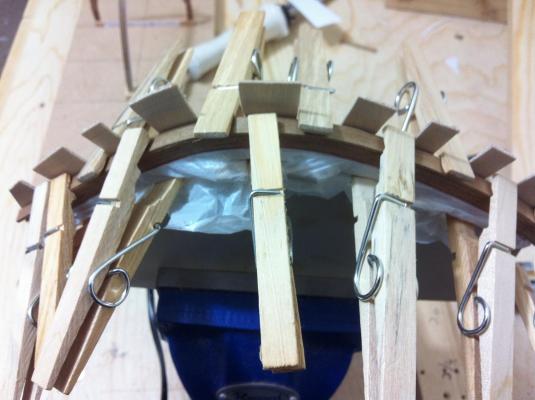
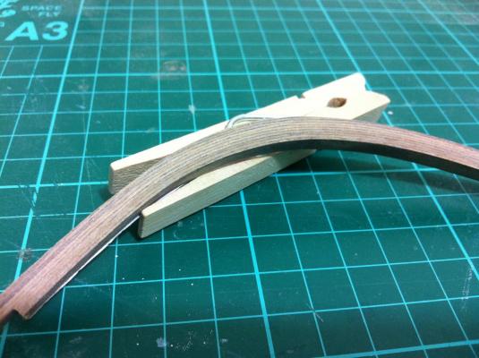
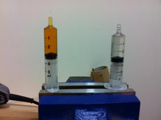
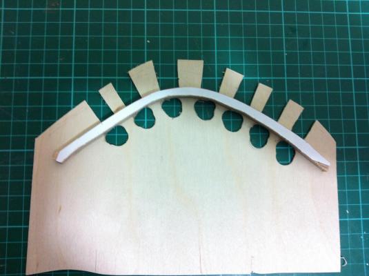
Ok, today I tackled the dreaded stem lamination. I took no risks this time. The strips have retained their shape well. I used super glue to attach a piece of supermarket plastic bag on the jig. And measured the resin and hardener very carefully! I added talk powder to peanut butter consistency. Fingers crossed this time!

- 253 replies
-
- 2
-
-
- ketkch
- gaff-rigged
- (and 1 more)
-
Your support is much appreciated Bob! I admit I should have read a book or two about modelling but it's more fun to built than read.
- 253 replies
-
- 1
-
-
- ketkch
- gaff-rigged
- (and 1 more)
-
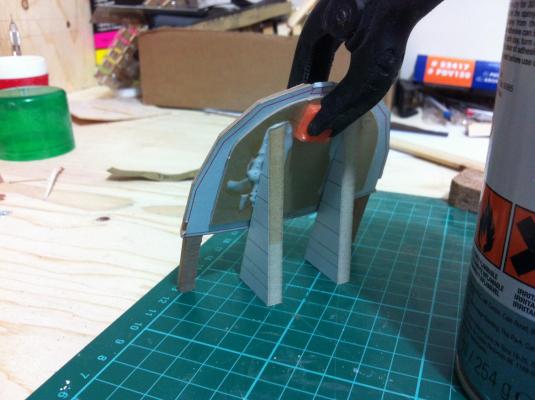
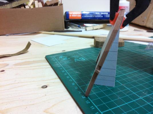
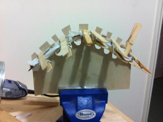
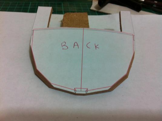
While the glue is setting on the last two frames I started working on the transom. I still have not found a solution how to hold it in place. I think some kind of jig will be needed. In Tad's plans (scaled down) the Transom is made of 1 mm plywood with a 3 mm frame. In my plans the transom is solid 4 mm. I will first bevel the transom and then maybe leave it as it is or maybe sand 1 mm off, cut the central part and glue plywood on the back. I do not have 4 mm thick sheet so I laminated 2 mm ones. The sheets are not perfectly flat so lots of clamps were needed! I did my first mistake and beveled the other way around the edge of the transom where it reaches the building line. No harm done though as I will need to built some kind of jig either way. I d rather do as much of the bevelling before assembly so I left only two narrow strips to reach the building line. Some of the bevelling could be done with the disc sander and the result was fantastic
- 253 replies
-
- 3
-
-
- ketkch
- gaff-rigged
- (and 1 more)
-
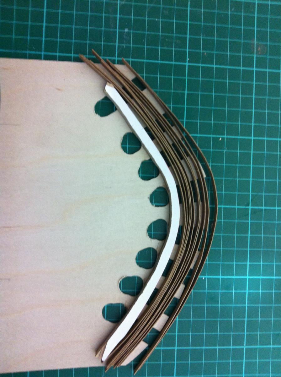
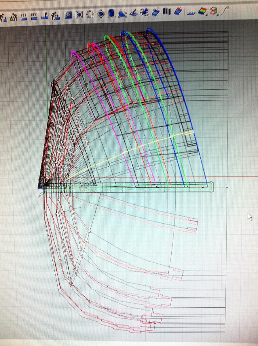
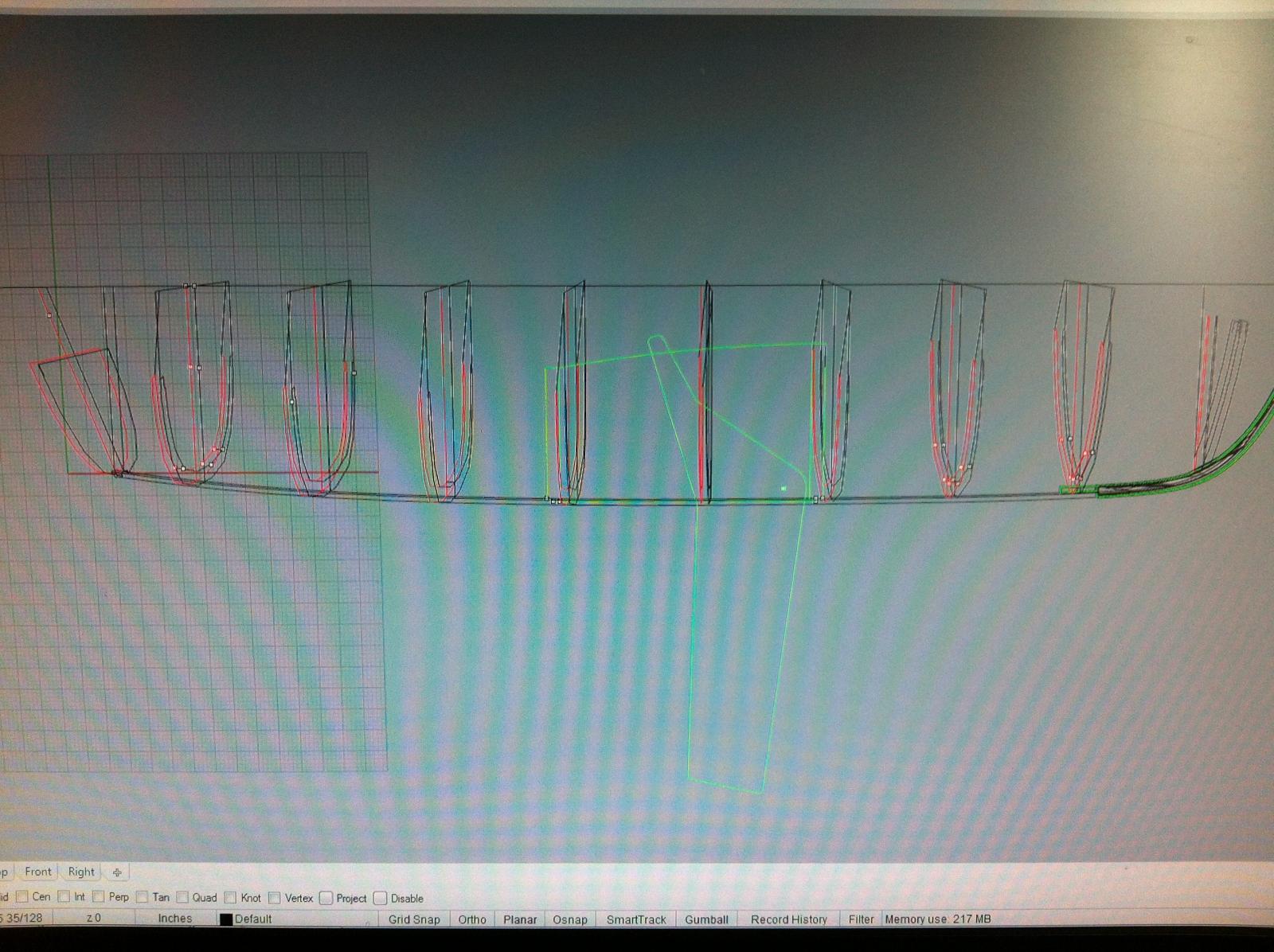
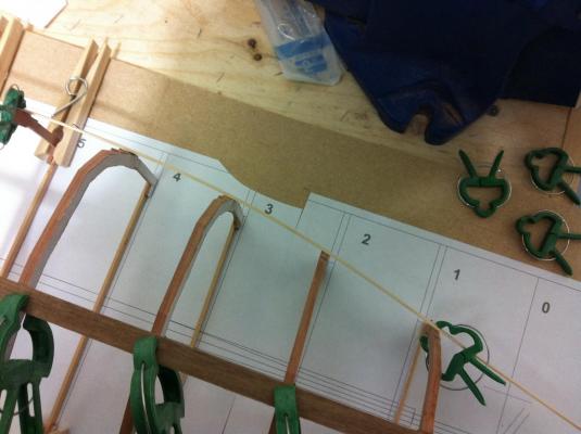
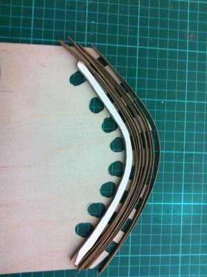
I checked the walnut strips, they have taken exactly the shape of the jig so I have high hopes this time all will go well with the stem. I realised I have not drawn the temporary form at station 0, where the cant frames will be. The yellow line is the one half of the form. This needs to be projected to the building line as the boat will be built upside down. I used 3 mm plywood and no bevelling as only the edge will touch the planking. So close to the stem the notches are very shallow. I also did some work on the cant frames. They are rather complex so careful sanding will be needed. I think I should leave these frames for after the planking has finished.
- 253 replies
-
- 1
-
-
- ketkch
- gaff-rigged
- (and 1 more)
-
Thank you John, you are absolutely right, trial and error showed this so I do exactly as you suggest. I am three quarters of the way finishing the frames, and I have started thinking how to tackle the transom problem. Also the cant frames look rather complex as well
-
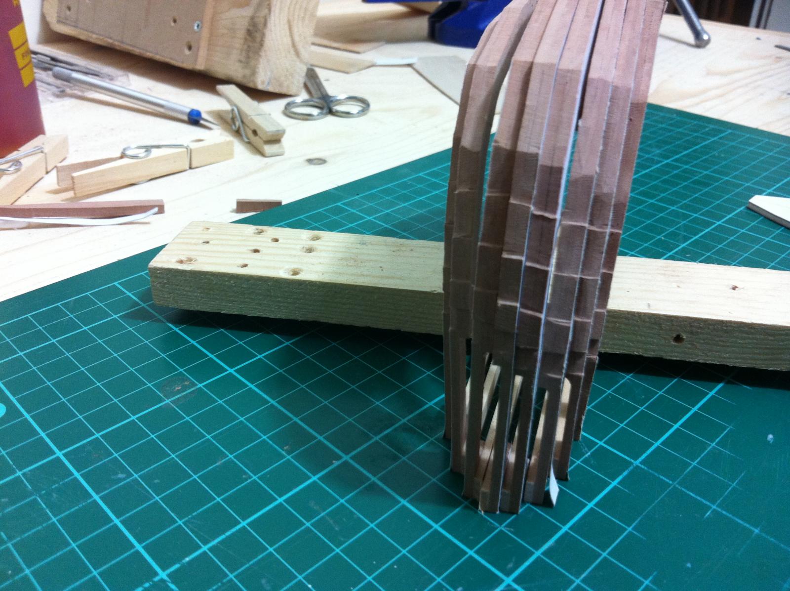
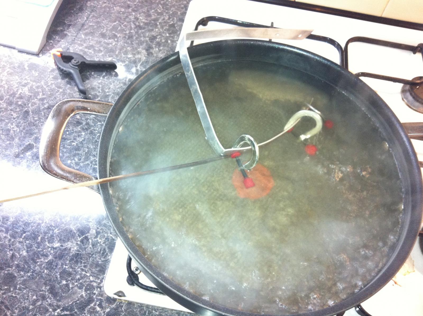
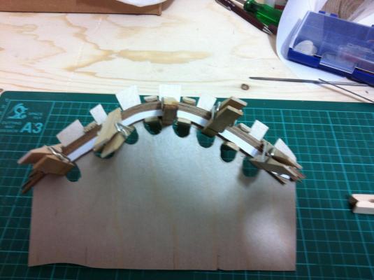
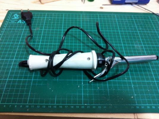
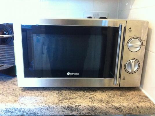
I tried the microwave but it did not work. Instead of heating the wood it completely dries it. The hair thingy however was instant and brilliant. Wet the strips and pass them through, taking care not to crush the wood. There seems to be a small learning curve of about 3 strips! All the strips now are on the jig waiting to cool down. I ll probably leave them overnight. The pressure from the pegs is gentle so hopefully the epoxy will not squeeze out this time
- 253 replies
-
- 2
-
-
- ketkch
- gaff-rigged
- (and 1 more)
-
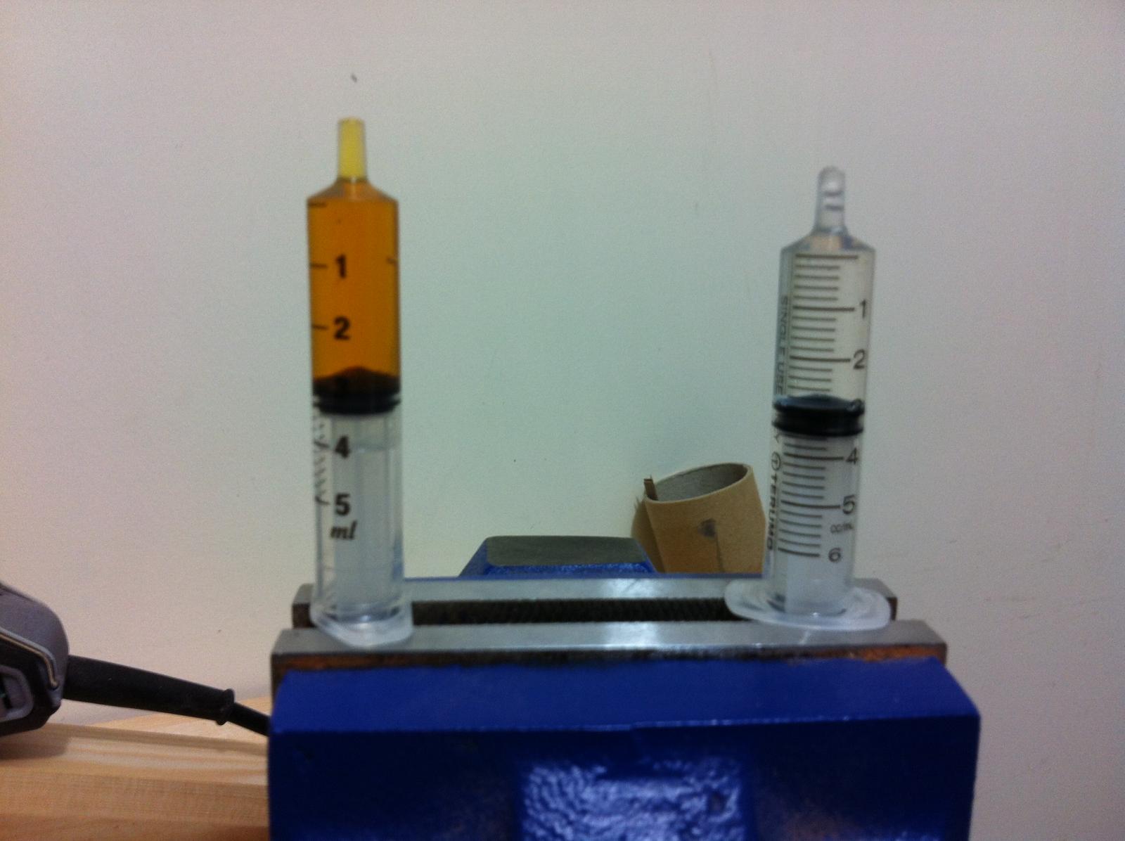
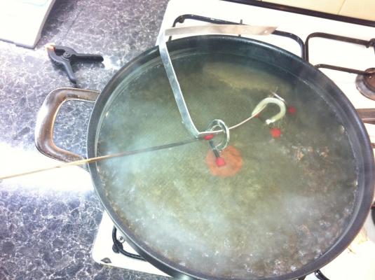
It is time then to bent the strips. But how to do it? Different options exist. 1. Stew the strips. From previous experience it works but it is very messy 2. Use my mother's old hair thingy 3. Microwave the strips
- 253 replies
-
- 2
-
-
- ketkch
- gaff-rigged
- (and 1 more)
-
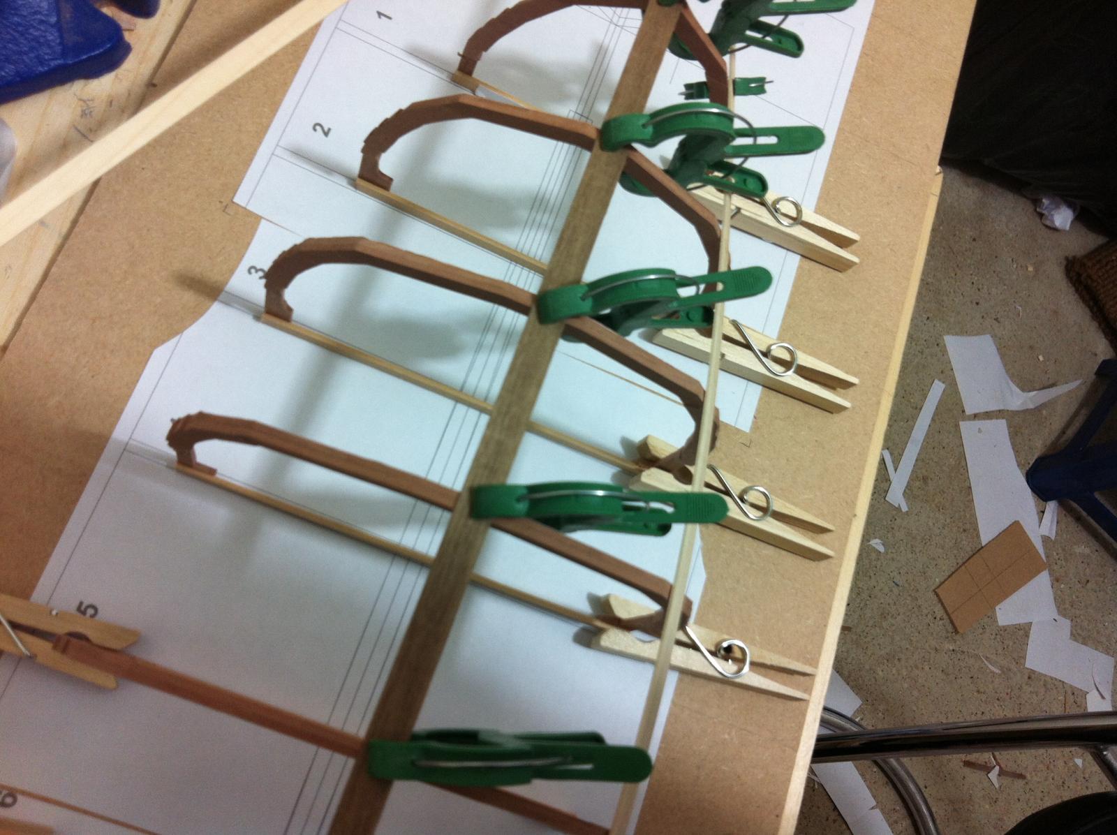
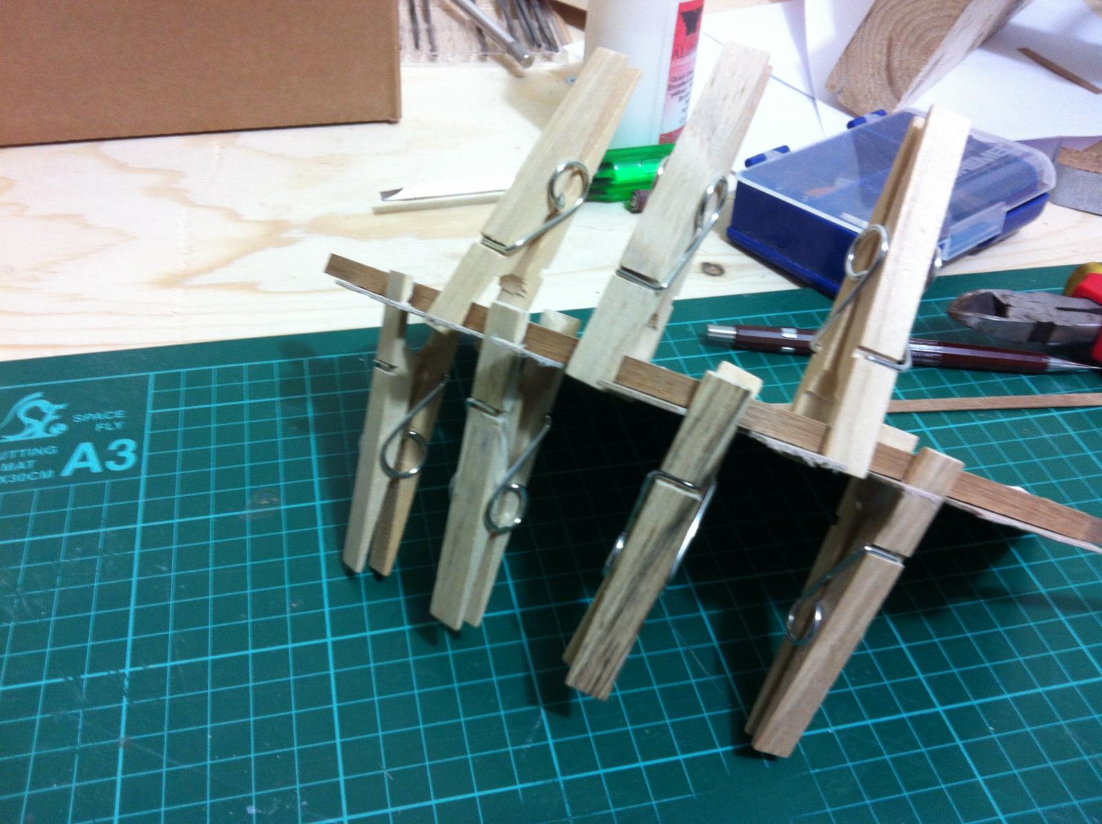
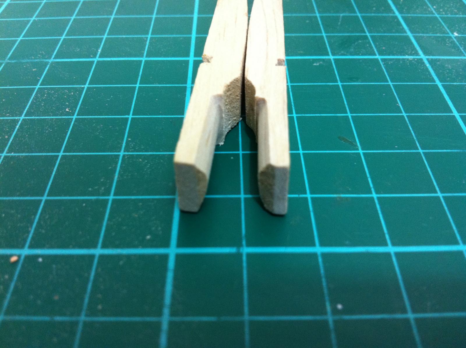
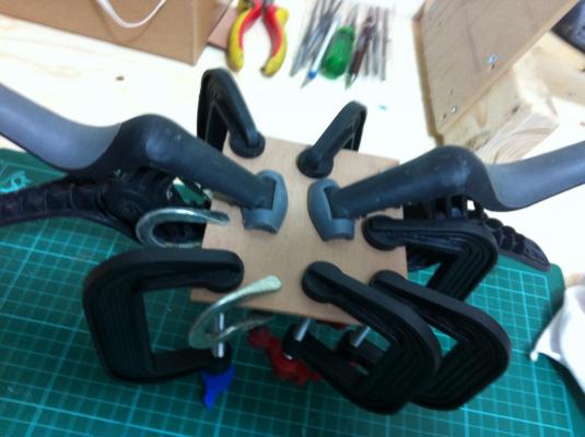
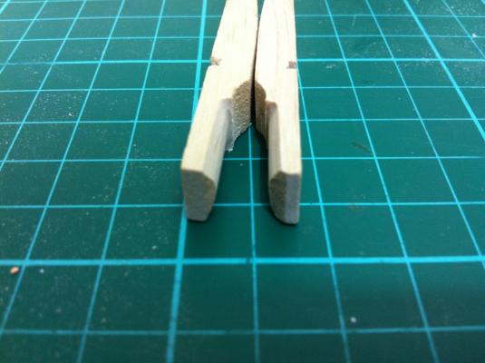
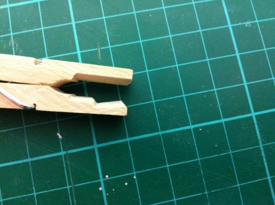
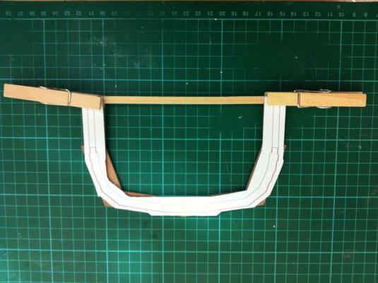
The previous jig was just pieces of wood nailed on the lofting table and this causes the clamps to compress the strips unevenly. I need clamps that will lie flat on the strips and that will not exert too much pressure. I decided to modify ordinary wooden pegs. I sanded the ends and gave them a slight curve However they still would not lie flat so a bevel was needed. All these were done in a flash with the disc sander which I must say is brilliant. I am still on the first 120 grit sand paper!
- 253 replies
-
- 2
-
-
- ketkch
- gaff-rigged
- (and 1 more)
-
Thank you Patrick! Still long way to go!
-
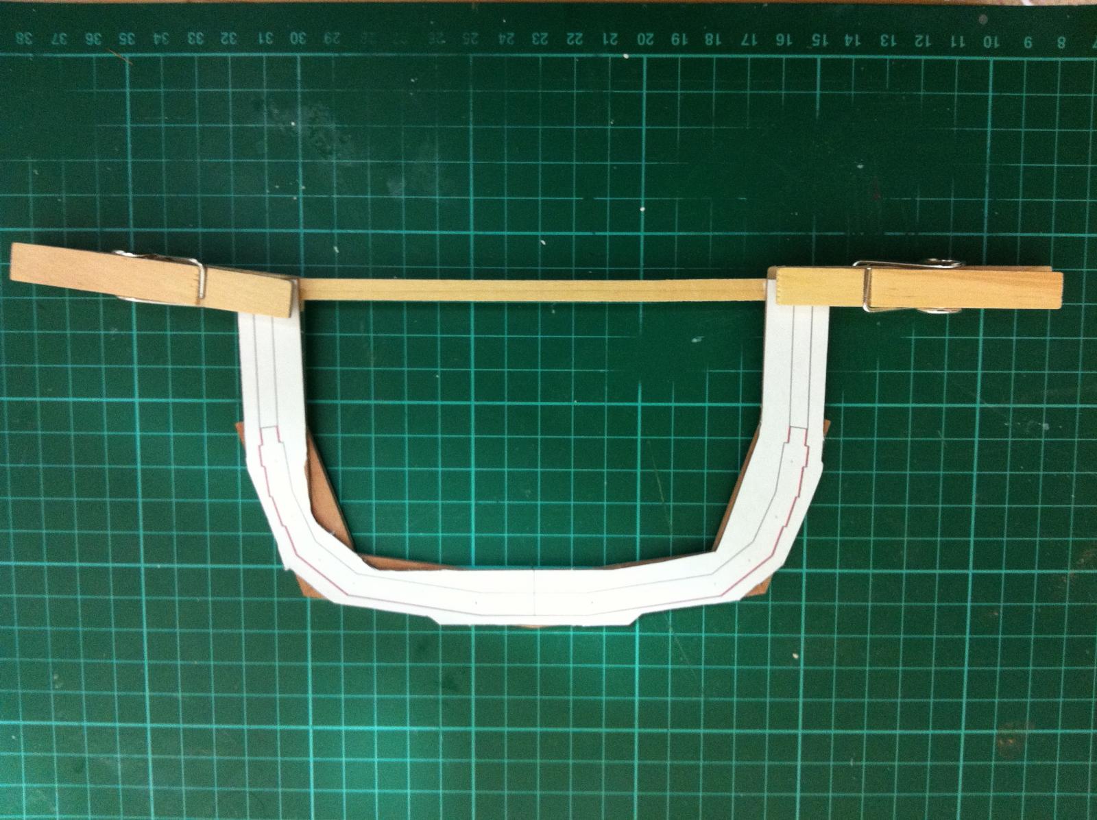
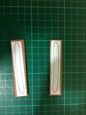
The process for making the frames seems to go well but I am still thinking about the disastrous results of the first attempt to laminate the stem. Since then I have done some studying and I feel ready to try again. I am thinking of using walnut as it is a very nice wood which sands nicely, steam bents and looks good. Also I can get 0.5 mm strips which I hope will minimise spring back. Anyway, I intend to steam bent the strips first. The first step is to built a jig. I had the design in my mind for some time so it took little time to produce it. I used offcuts of MDF and 1mm plywood. Again I am afraid the result is far from elegant!
- 253 replies
-
- 2
-
-
- ketkch
- gaff-rigged
- (and 1 more)
-
Thank you John, i will need all the support I can get! Back to the frames, even just glued on the edge the pieces hold together very securely. The disk sander makes sure that the edges are perfectly square. The alignment pins are inserted, the joints are lightly sanded and the pieces are set back to back, the contact areas outlines and then glued The frame pattern is glued and a strip added to strengthen the frame Then the scroll saw and the disc sander are used to cut along the pattern. The final sanding and the bevelling are done with the needle files. It is too early to tell but the notches and bevels don't look too far off. Certainly there is a world of difference to the previous attempt. I might need to deepen the notches but the amount of wood to be removed will probably be small


- 253 replies
-
- 4
-
-
- ketkch
- gaff-rigged
- (and 1 more)
-
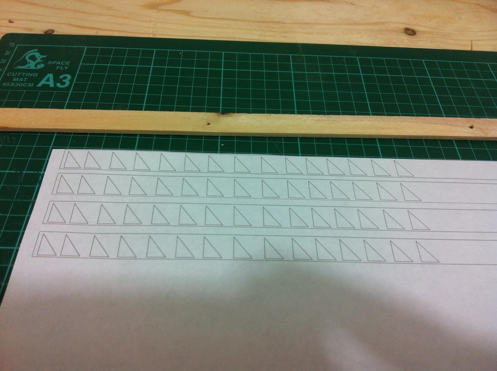
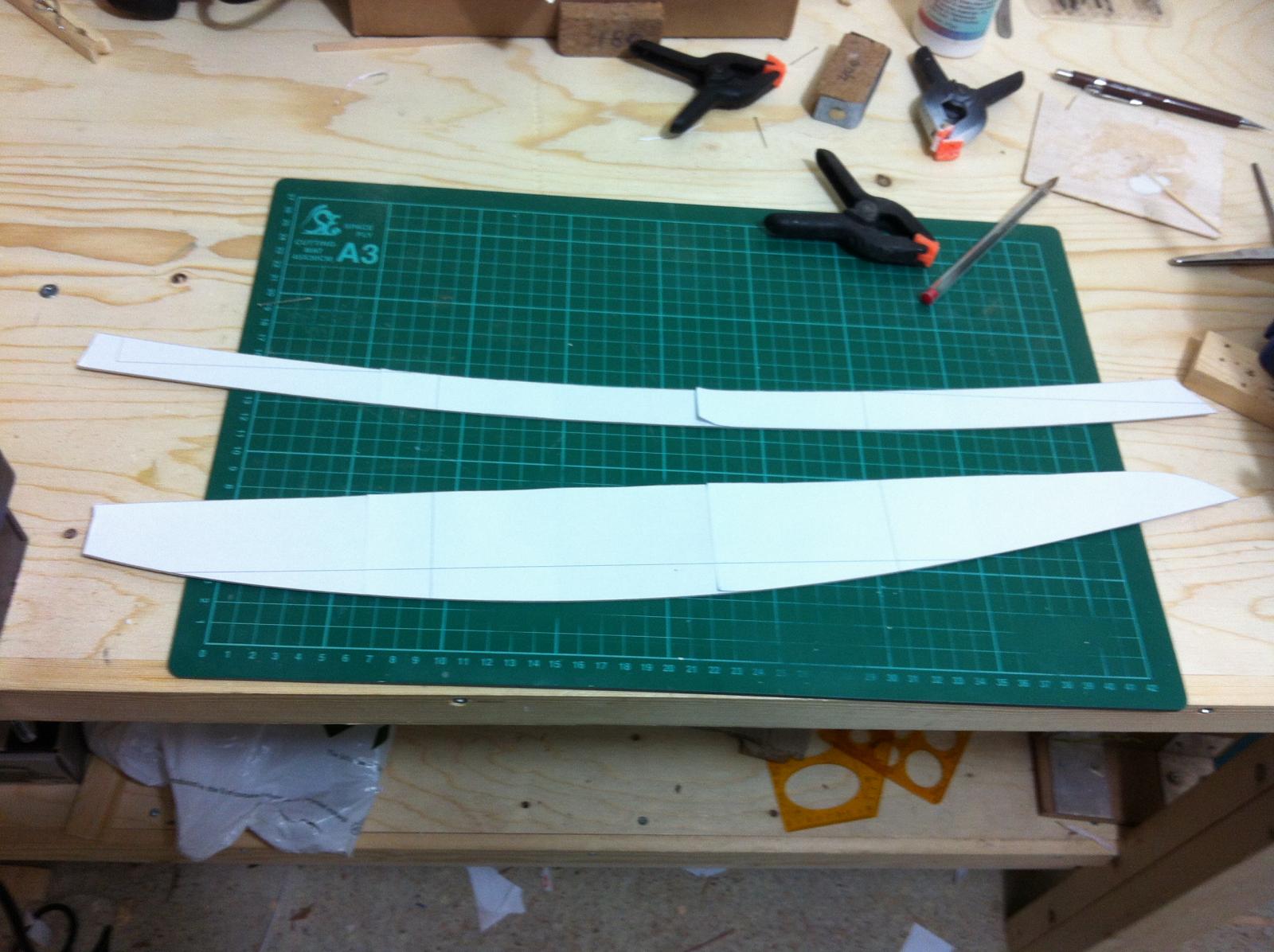
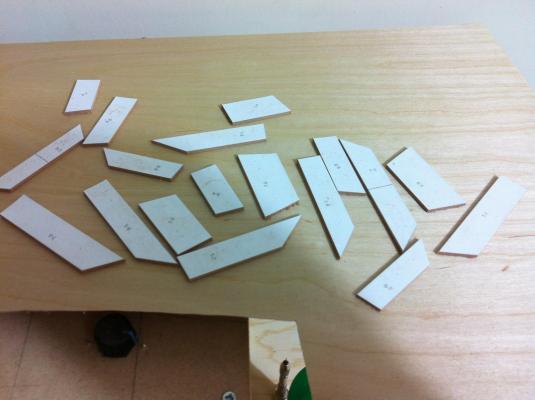
Back to the boat now. The frame segments are cut initially with the saw and finished with the disc sander. Then they are assembled on the paper pattern and edges glued together. Dots placed on the print outs are used to align everything. This produces very accurate results. Using power tools makes a world of difference. Also pear is so much nicer than lime and despite being much harder seems to sand as easily. The spray glue does not penetrate the wood and is very easily removed with isopropyl alcohol.

- 253 replies
-
- 4
-
-
- ketkch
- gaff-rigged
- (and 1 more)
-
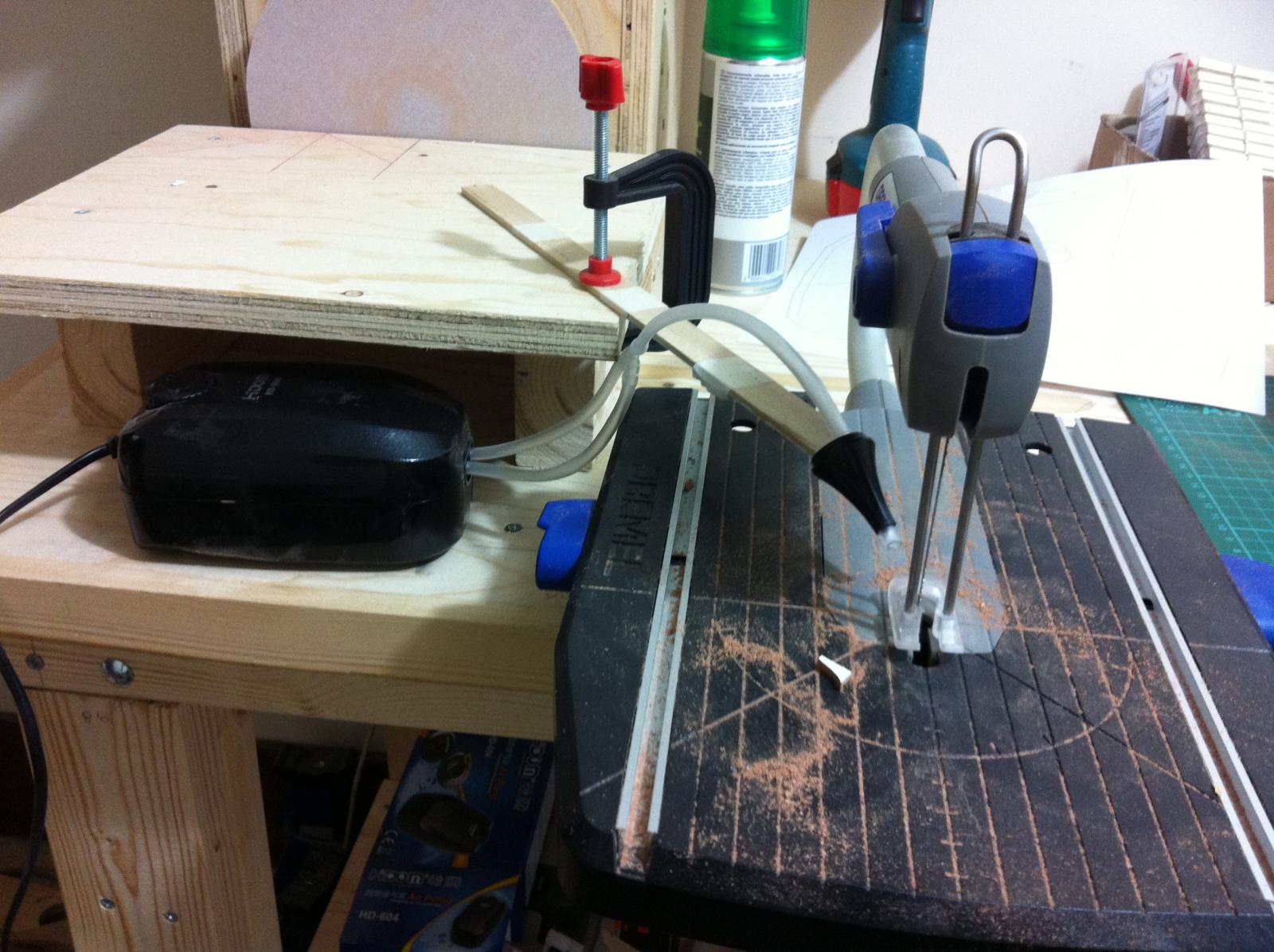
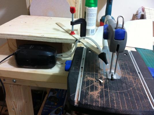
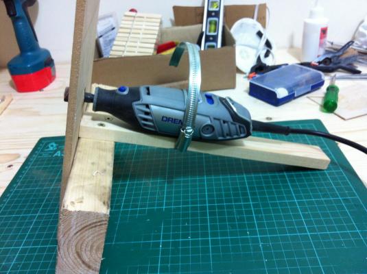
I think maybe expand a bit on the tools. For a scroll saw a blower is necessary and indeed a fish tank pump works brilliantly and is silent. it is the black box next to the saw. I got a strong one but really even the weakest one would be fine. The holding mechanism is temporary, I ordered a coolant lathe hose. I thought also a router (kind of) might be useful so I improvised a bit and the assembly is solid and square. I am sure all these could be made more stylish but at least they are functional!
- 253 replies
-
- 3
-
-
- ketkch
- gaff-rigged
- (and 1 more)
-
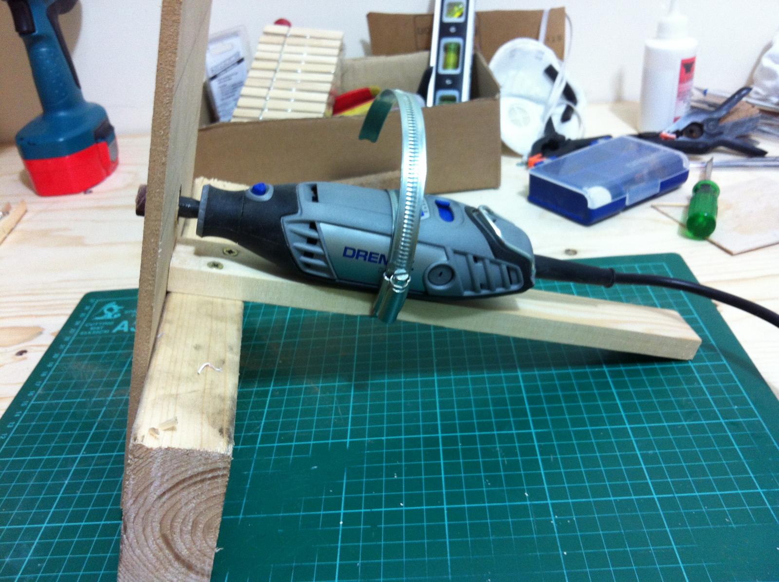
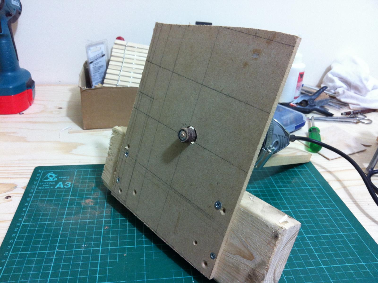
Thank you both, actually it does not get hot at all. This is a drill made almost entirely of steel, very heavy and It gets used only for short periods of time. Also pear seems to produce larger particles so there is little dust and the sand paper does not get clogged. I played with the idea of self adhesive sand paper but in the end i varnished the MDF, sand it down to 400 grit and used ordinary sandpaper with re-positionable spray glue. It works perfectly and now I wonder how I lived up to now without one.
- 253 replies
-
- 1
-
-
- ketkch
- gaff-rigged
- (and 1 more)
-
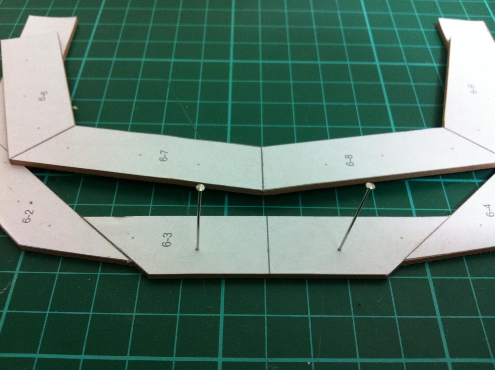
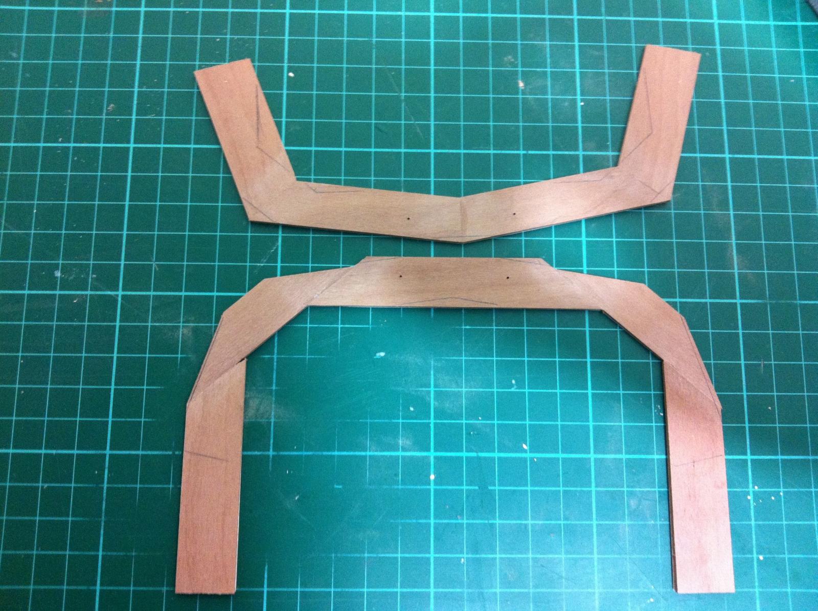
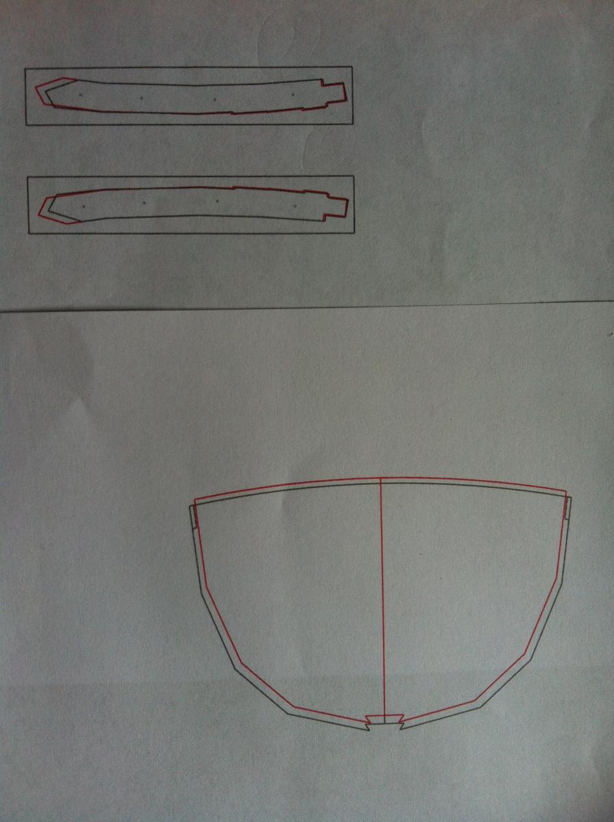
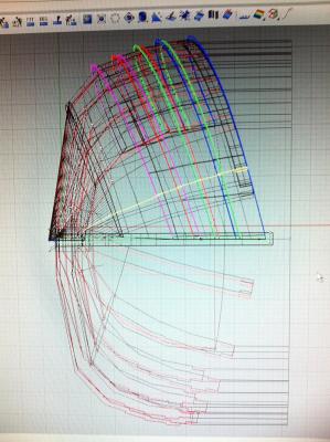
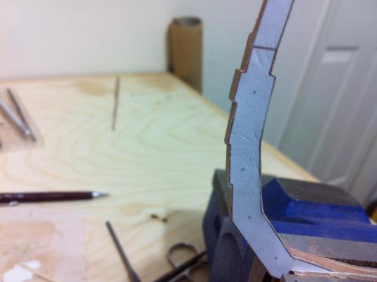
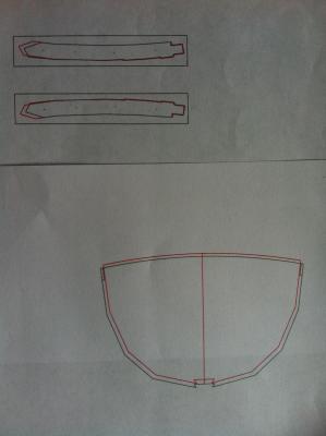
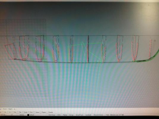
I am ready to start cutting the frames. I am posting a photo of the cant frames and the Transom where the bevelling is shown. Initially there will be a temporary form instead of the cant frames and I will need to think of something to hold the Transom securely. Also, Tad does not give precise dimensions for the centerboard but the computer program was again very helpful
- 253 replies
-
- 5
-
-
- ketkch
- gaff-rigged
- (and 1 more)