.jpg.f26acc9a74319261612561bfa7da1303.jpg)
vaddoc
-
Posts
1,605 -
Joined
-
Last visited
Content Type
Profiles
Forums
Gallery
Events
Everything posted by vaddoc
-
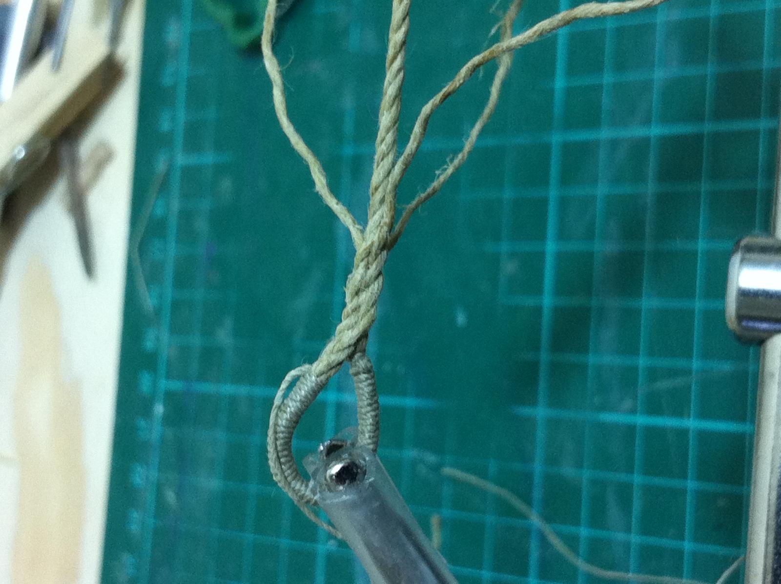
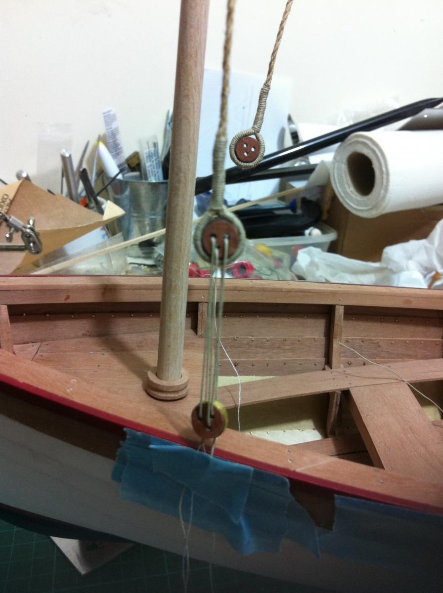
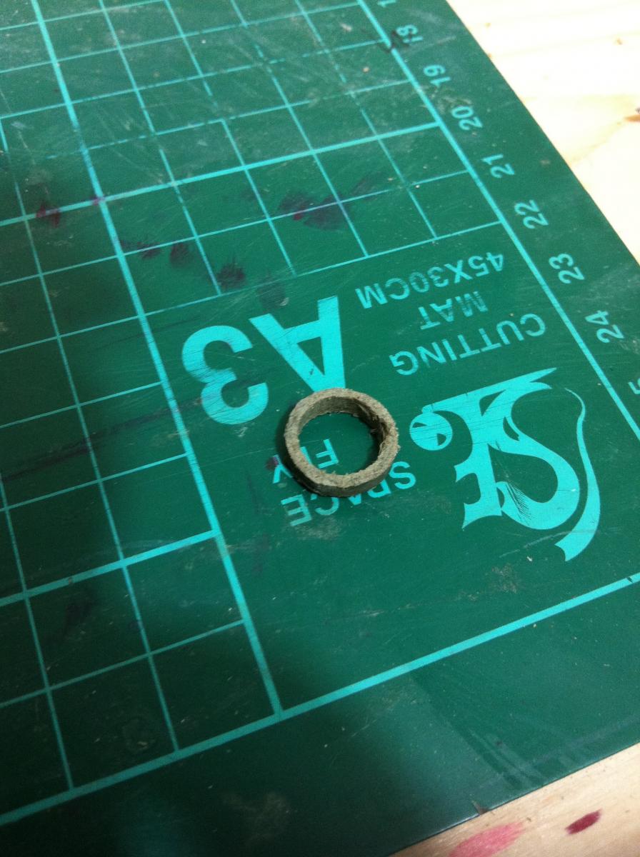
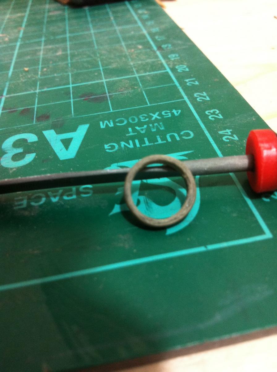
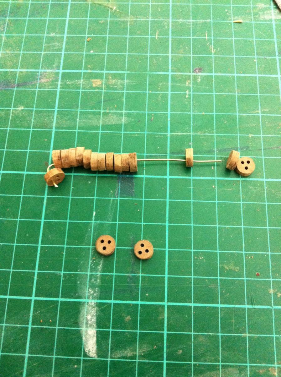
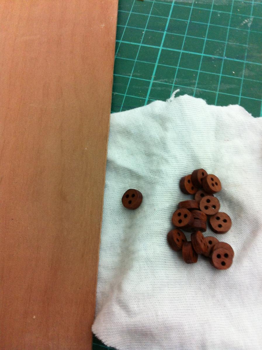
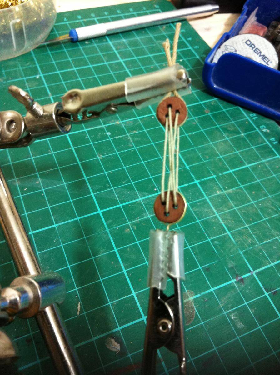
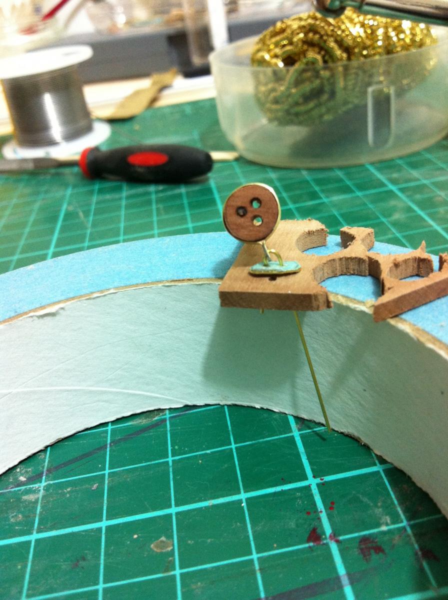
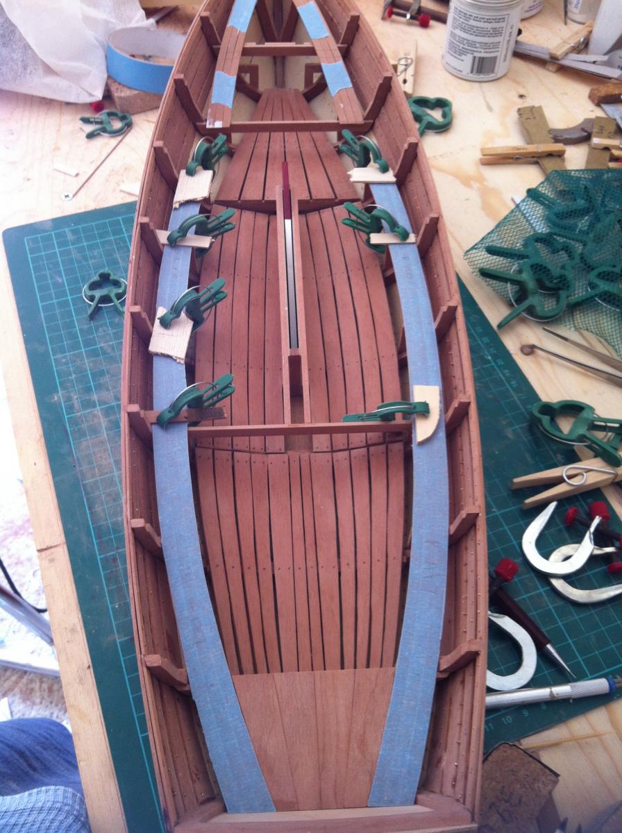
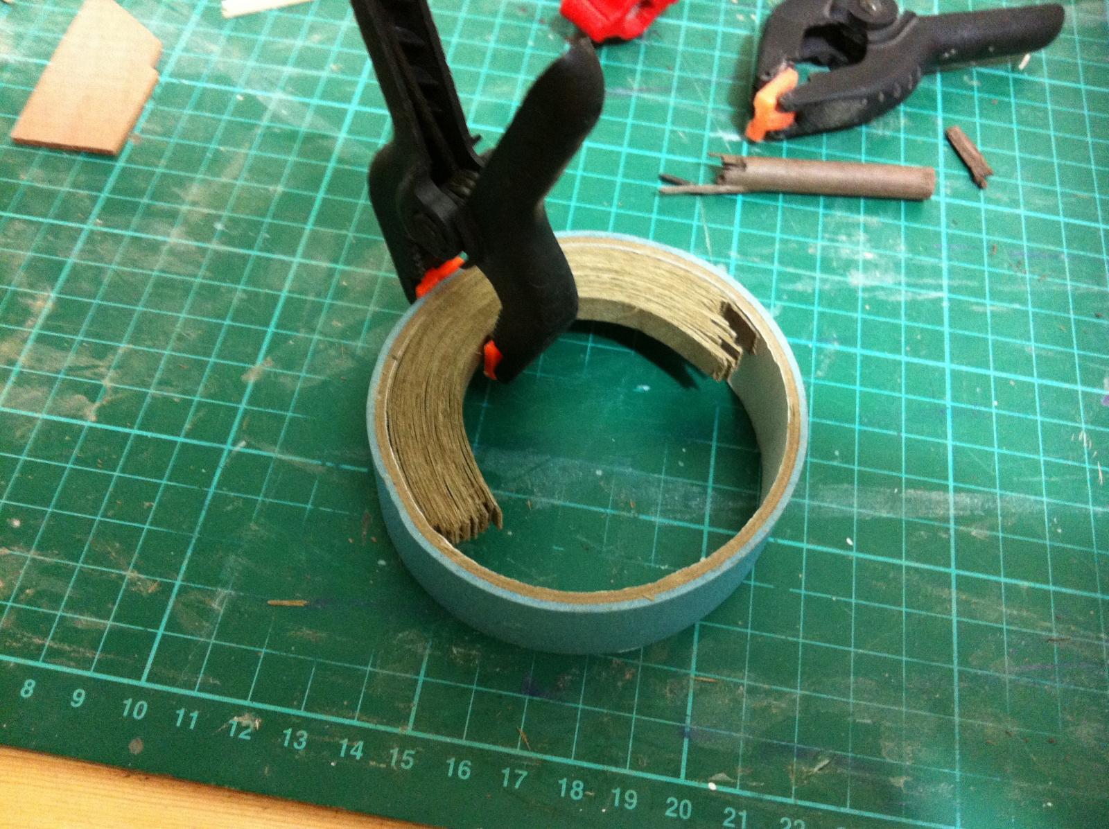
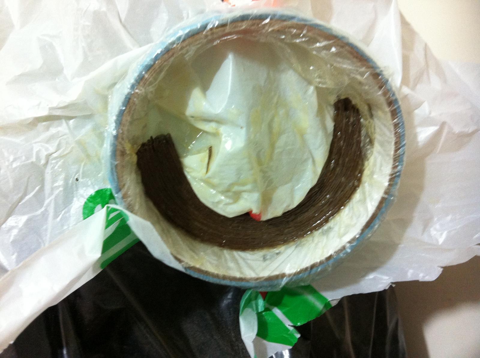
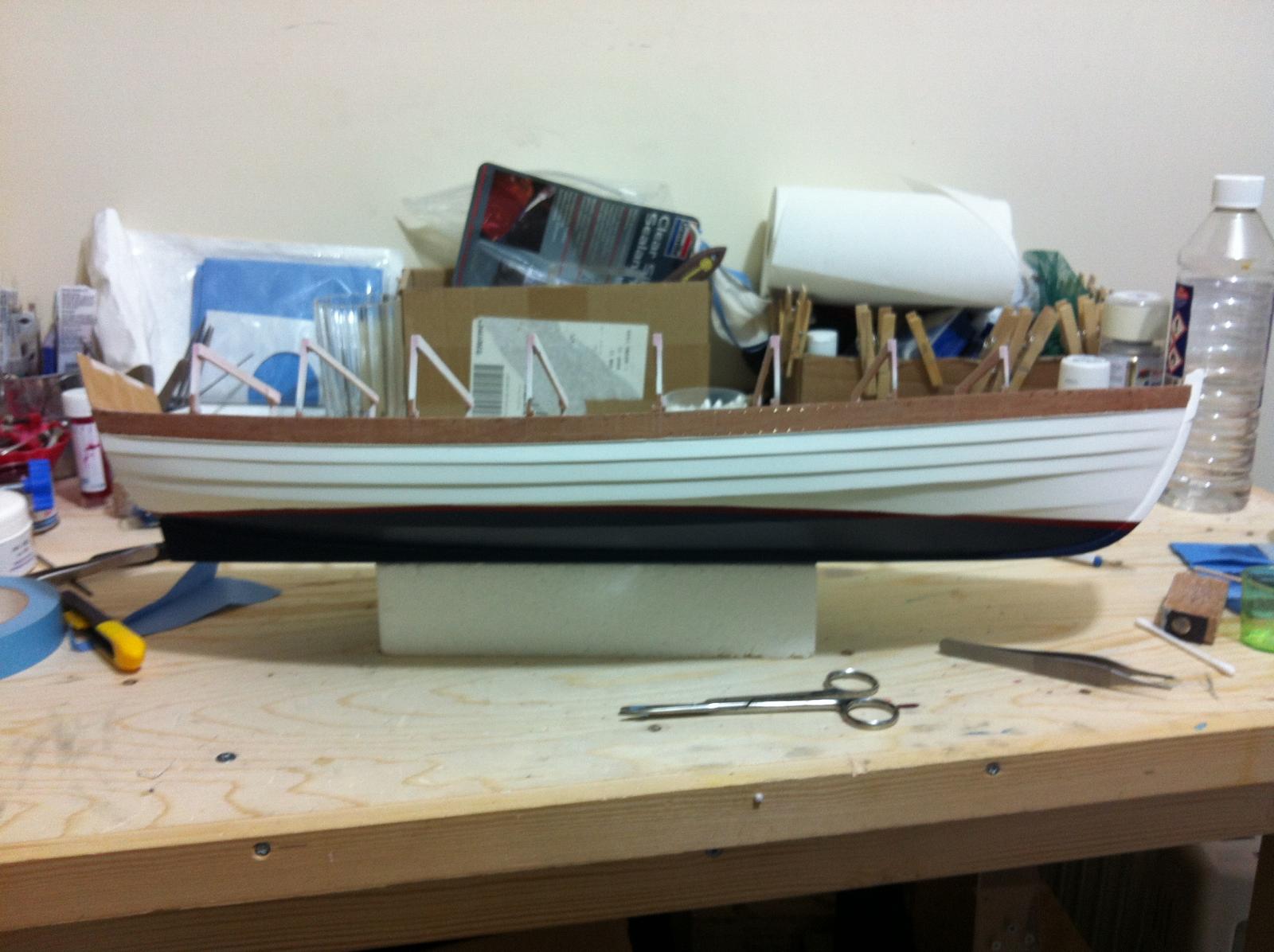
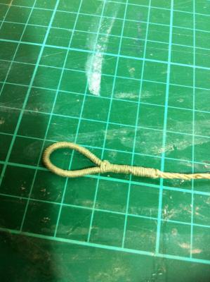
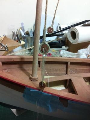
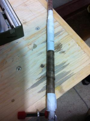
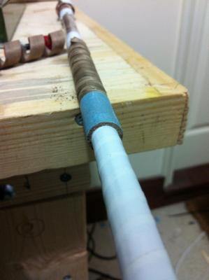
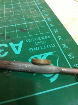
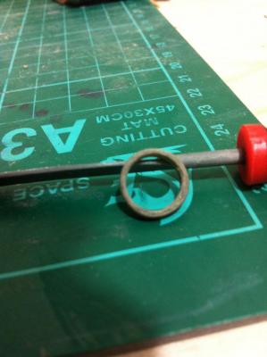
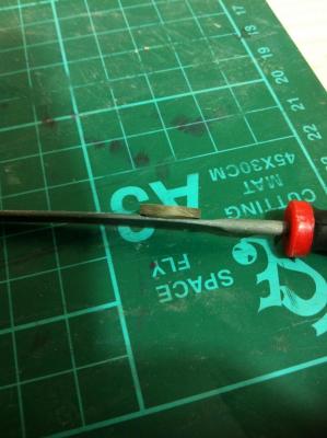
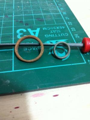
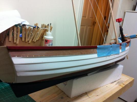
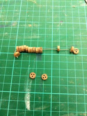
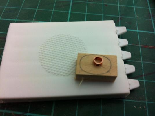
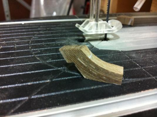
.thumb.jpg.6fd4c1b78768bb3efd745ab810936005.jpg) Dear all, things are going well so I think another quick update is in order. I have all the components for my rope serving machine and will put it together when time will permit but in the meantime I discovered that it is not really needed, at least not for the very large scale rope I am using. In any case, the first attempt in serving and splicing rope was entirely successful. I also think it does not look too bad although I am not sure if the scale is correct. This is how it will look in the end I also started making some hoops for the mast. The only suitable strips I had were walnut, I don't think the colour matches the boat very well but with a coat of tung oil it might work. I rolled a wide strip around a dowel and then I glued another strip on top to form a tubular laminate. Then I sawed a slice off and a very nice hoop came out. I sanded it smooth and then reduced its width. Still, the previous mahogany version I think looks better I also am working on the rudder, still needs some more coats of paint and varnish but I think soon it will be time to mount the hinges.
Dear all, things are going well so I think another quick update is in order. I have all the components for my rope serving machine and will put it together when time will permit but in the meantime I discovered that it is not really needed, at least not for the very large scale rope I am using. In any case, the first attempt in serving and splicing rope was entirely successful. I also think it does not look too bad although I am not sure if the scale is correct. This is how it will look in the end I also started making some hoops for the mast. The only suitable strips I had were walnut, I don't think the colour matches the boat very well but with a coat of tung oil it might work. I rolled a wide strip around a dowel and then I glued another strip on top to form a tubular laminate. Then I sawed a slice off and a very nice hoop came out. I sanded it smooth and then reduced its width. Still, the previous mahogany version I think looks better I also am working on the rudder, still needs some more coats of paint and varnish but I think soon it will be time to mount the hinges.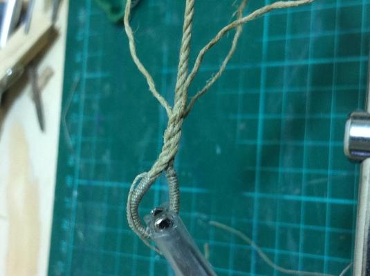

- 253 replies
-
- 10
-

-
- ketkch
- gaff-rigged
- (and 1 more)
-
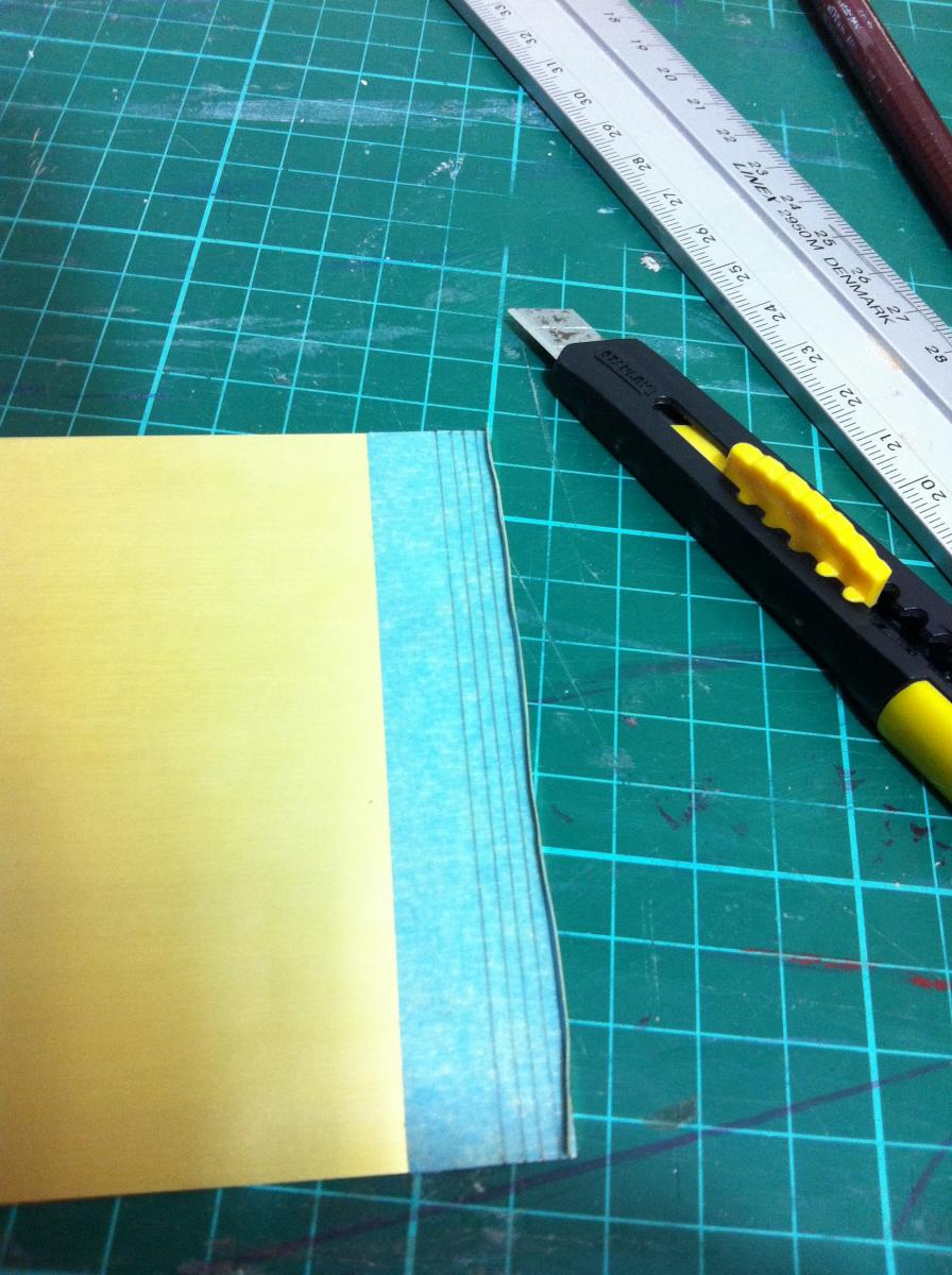
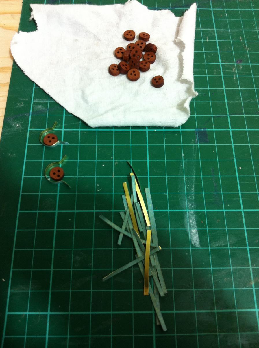
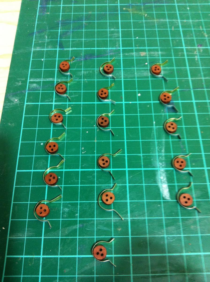
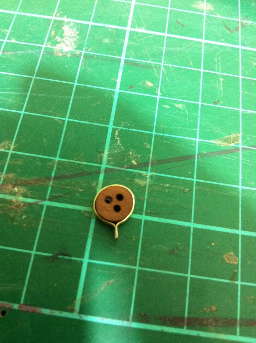
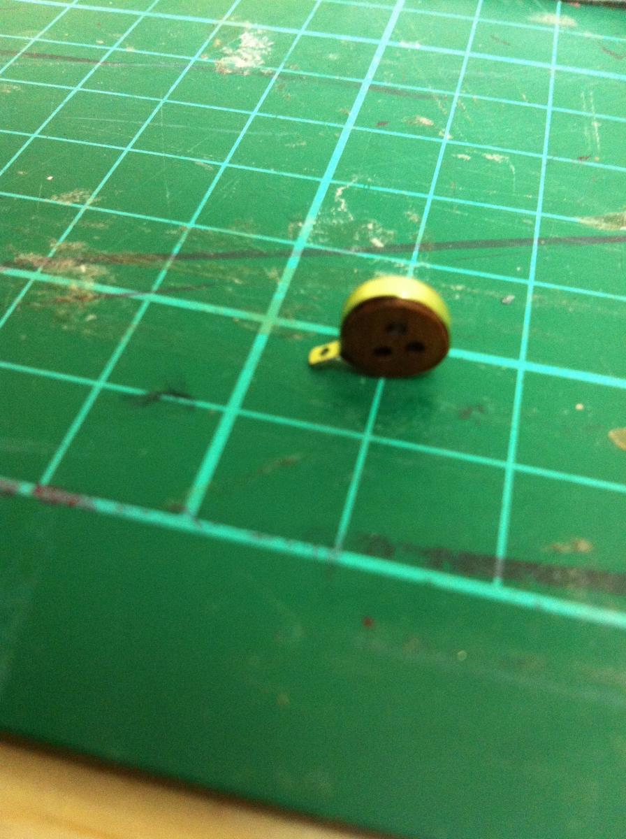
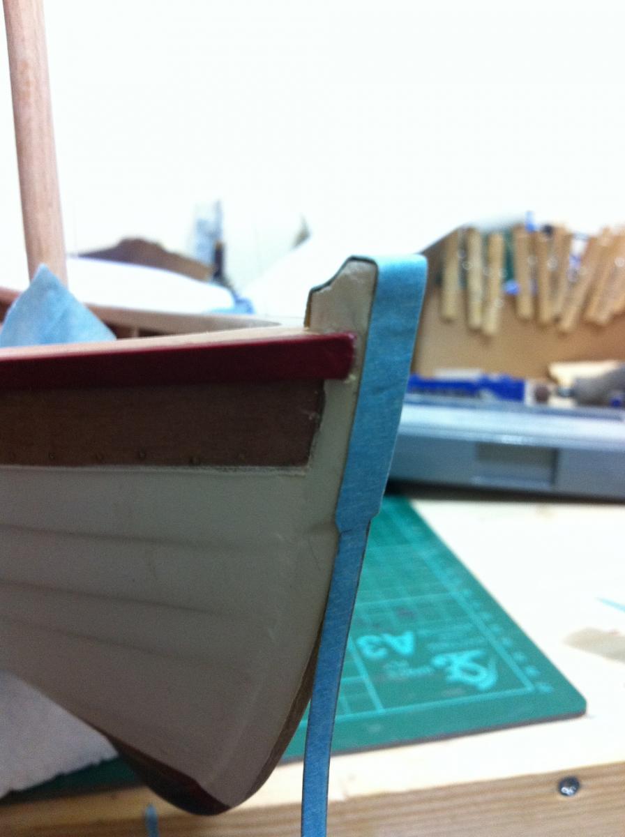
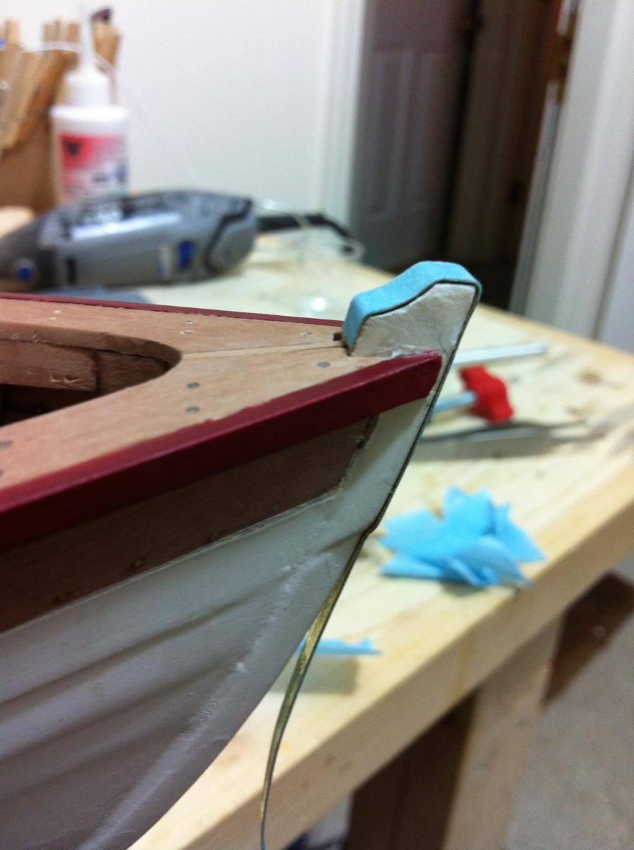
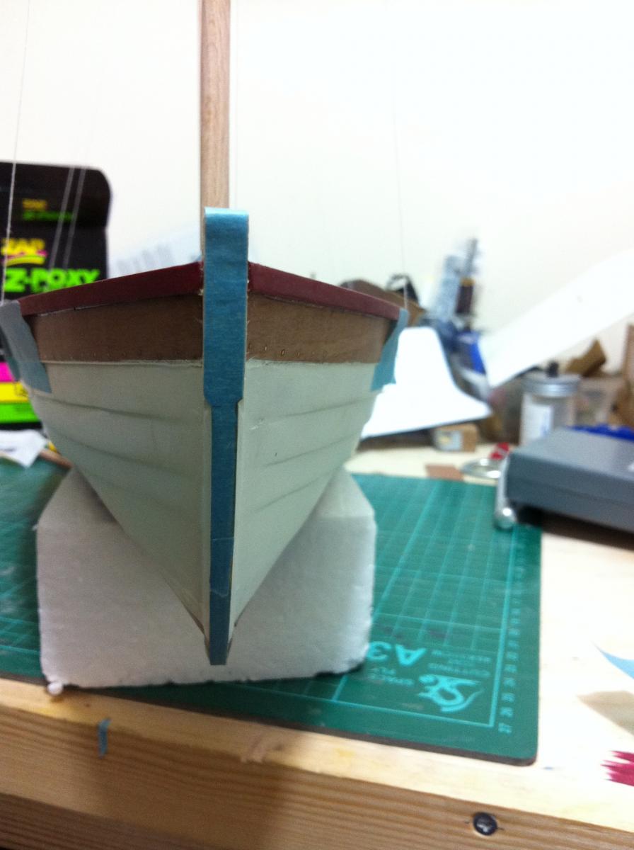
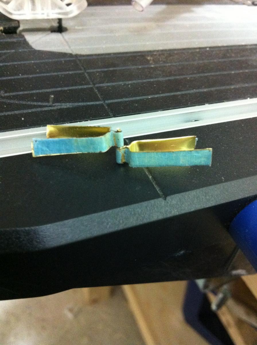
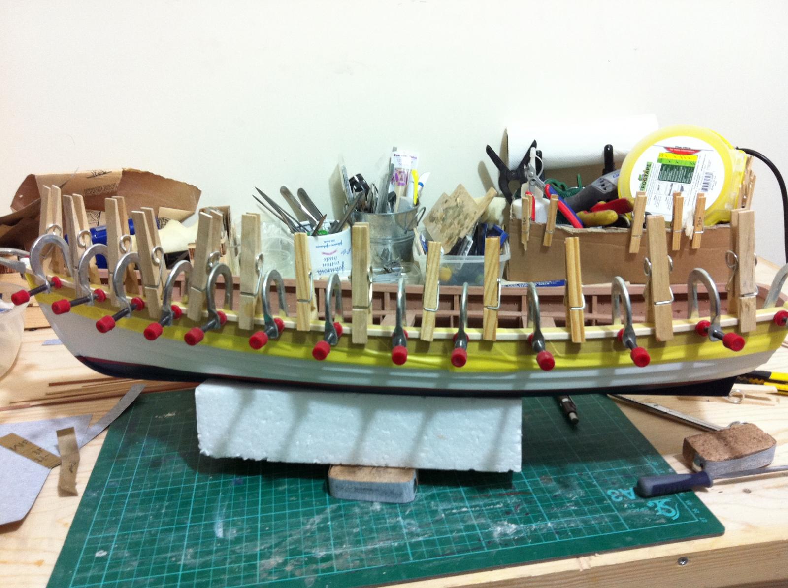
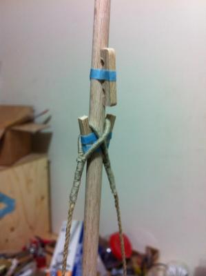
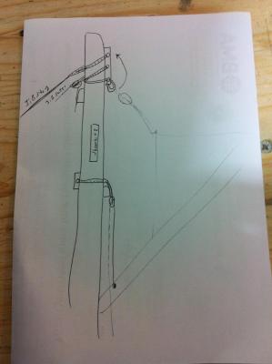
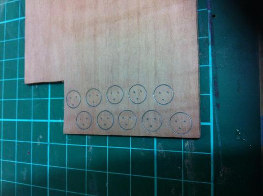
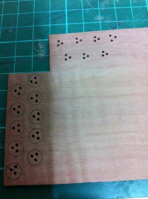
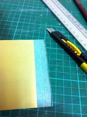
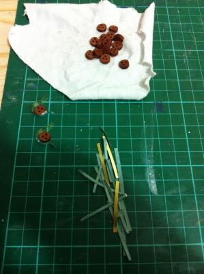
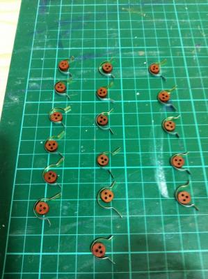
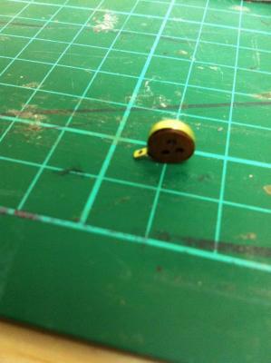
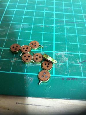
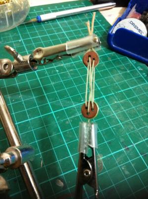
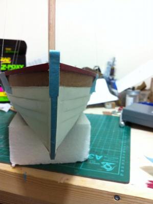
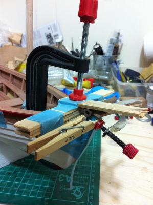
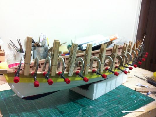
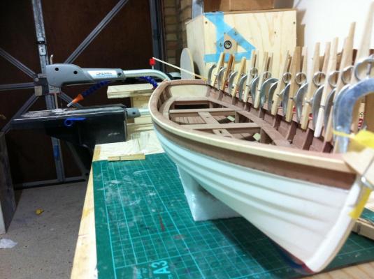
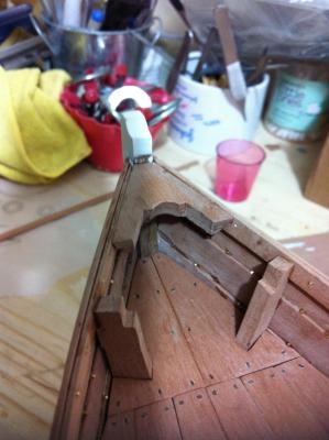
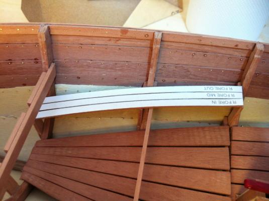
I think it is time for an update although small actual progress has been achieved. The main thing is that I changed my mind regarding the rigging. I finished painting the rub rails, they came out fine. I also made a new tiler as I was not happy with the first attempt. I think it looks better. I have been thinking about the rigging for a long time and I realised I was not happy with the arrangement I had decided on. I want a more traditional look and to avoid the use of all modern gear like turnbuckles, shackles, wire ropes etc. I also want a accurate representation of the actual rigging. I spent a lot of time researching and I now have a very clear idea of how it will be arranged. The drawing shows the rigging of the main mast: The main mast will have one pair of shrouds and a pin rail probably attached to the small deck. The mizzen will have two pair of shrouds and a pin rail attached to the shrouds. This means served ropes and deadeyes. So here it goes. I started making the dead eyes which was actually easier than I thought. Lots of little faces watching me! Cutting strips of brass with the knife was easy. Tung oil deepens the colour nicely And then all came together, soldered and sanded to shape. An easy job although I got carried away and made more than I actually needed. The dead eyes will be secured to the boat with brass fittings. There will be need for splicing rope and of course serving. I tried serving by hand and immediately I gave up, this really needs a machine. I tried making a serving jig with whatever I had int he garage but gave up. I will try again though, I think I can make it work. Back to the boat, i prepared and glued in place the brass strip on the false stem which needed a rather complex clamping system. I have left the masking tape on to protect the shine of the brass. I will add later on an eye bolt for the jib. Next to paint the rudder and attach the tiler and brass fittings and of course to have another try in making a serving jig.


- 253 replies
-
- 4
-
-
- ketkch
- gaff-rigged
- (and 1 more)
-
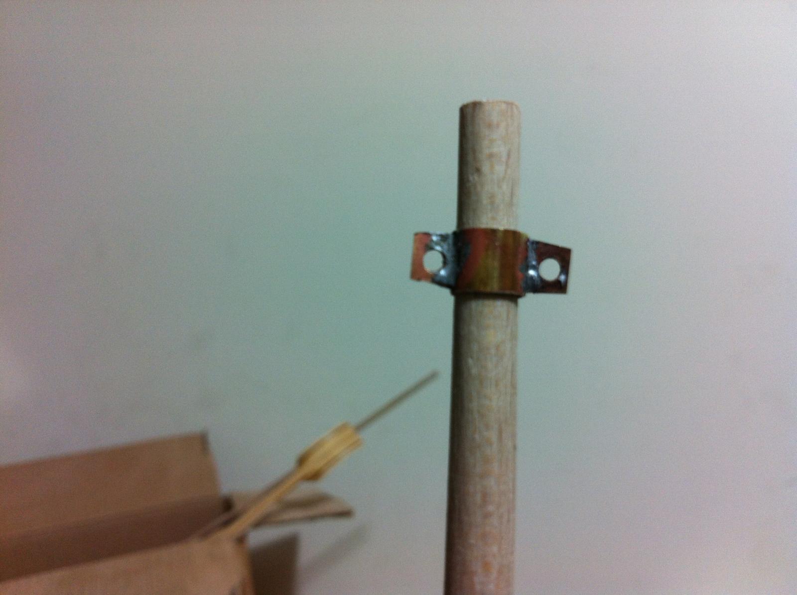
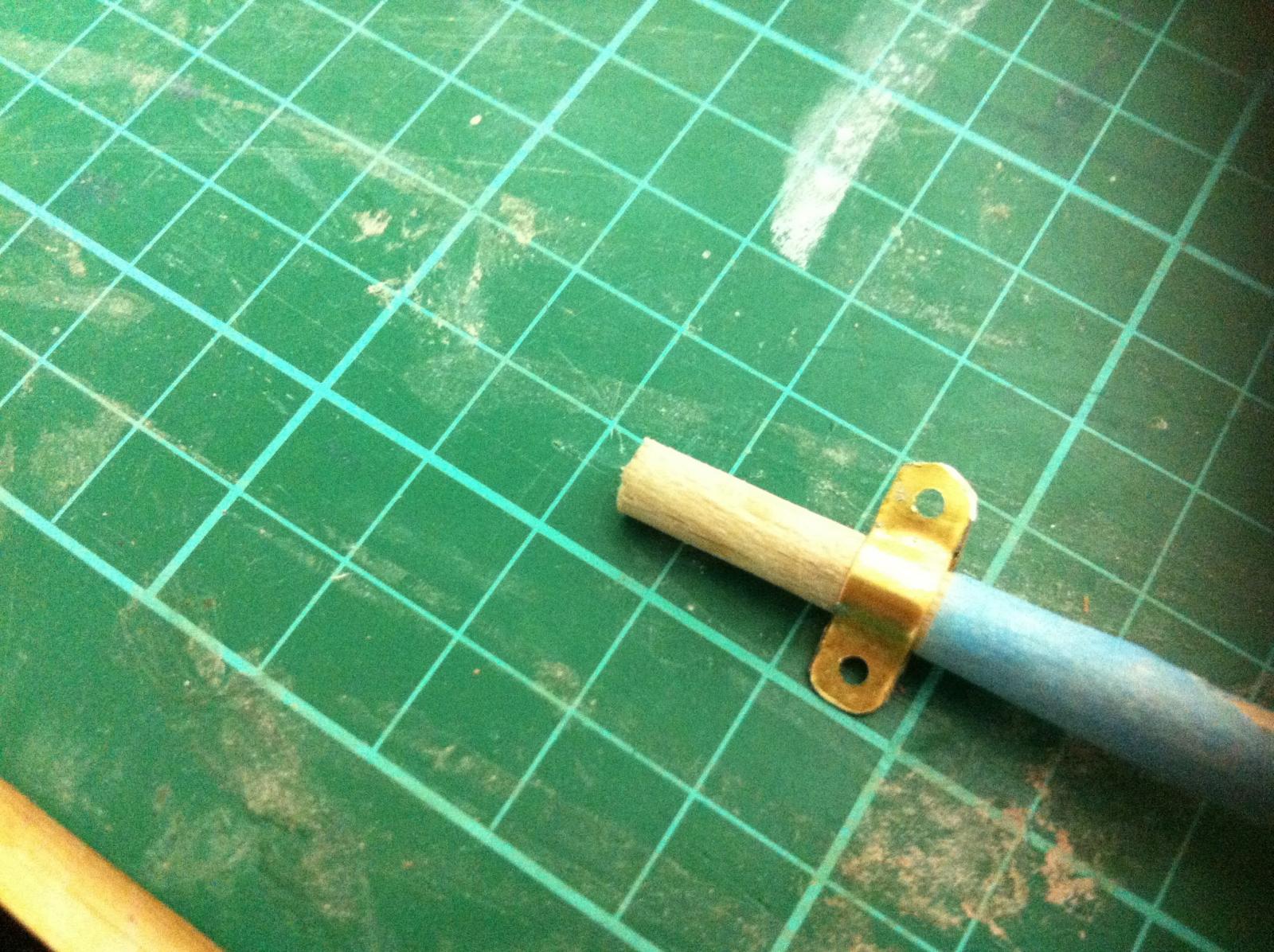
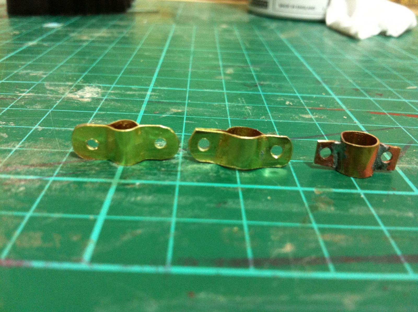
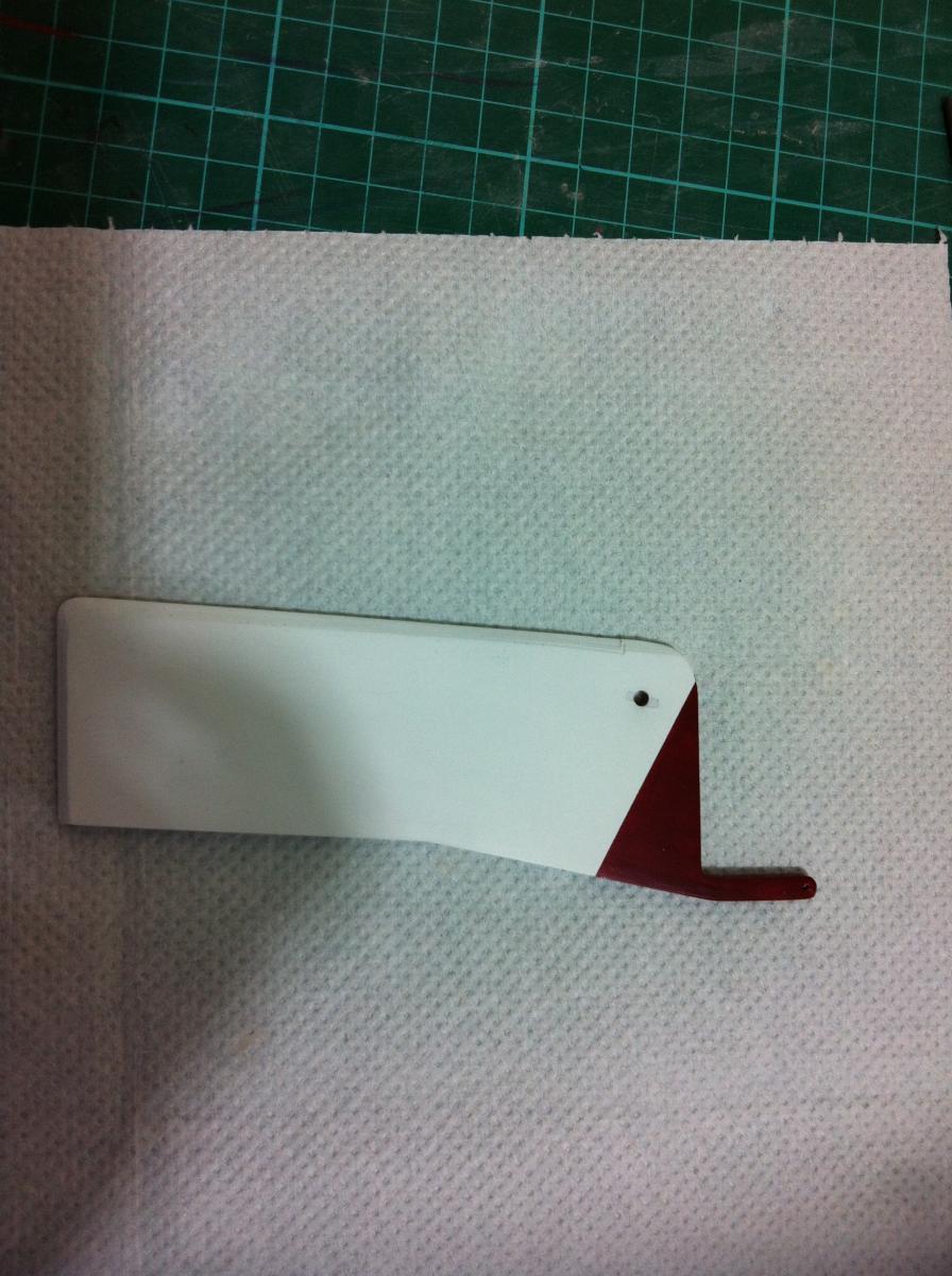
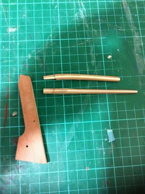
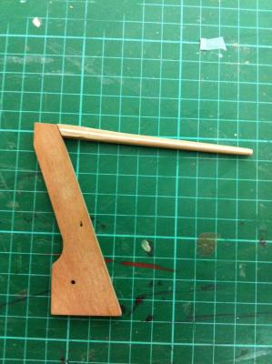
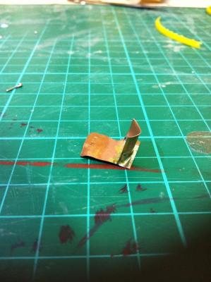
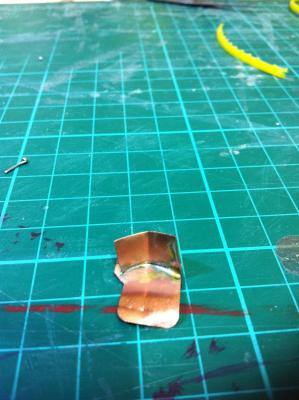
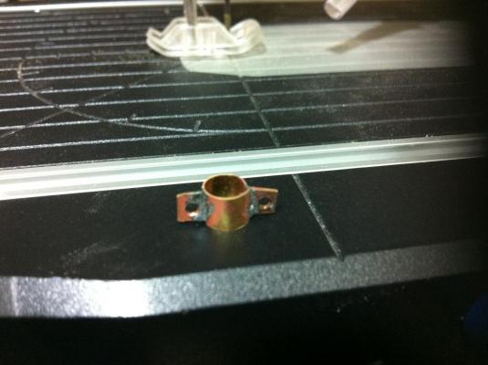
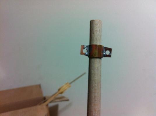
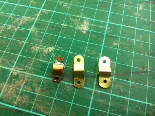
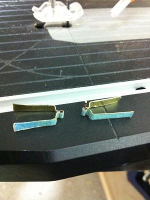
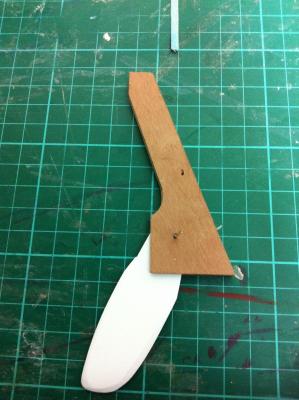
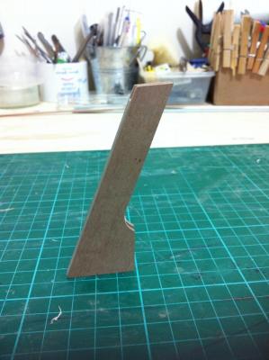
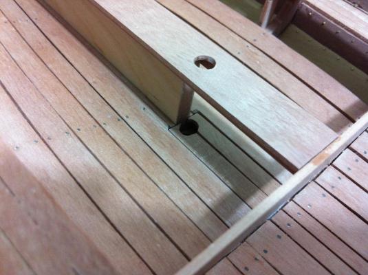
Progress is slow but there is definite progress. The soldering equipment arrived and I started experimenting. I will never be able to bent the metal to my will like Michael does but I am happy to report I can now solder two pieces together! These are photos of my first ever attempt in soldering. I found two suitable strips in my inventory and glued the rub rails in place which was again a rather fiddly job. I then started work on the mast fittings for the shrouds. The first attempt was not really very nice... The second time though I think it came out ok. I made fittings for both masts and put a coat of rennaissance wax to protect the shine. I also did more work on the rudder. It still needs painting though. The small hole above the one for the blade axel is for the rope that extends the blade. I then decided to have a go at the hinges. I think they look ok! I also finished painting the rub rails. Much still left to do!


- 253 replies
-
- 6
-
-
- ketkch
- gaff-rigged
- (and 1 more)
-
Dear Patrick, I am very happy that all went well with your operation, hopefully you ll get over this incident very soon. As for the boat, this is such a nice and unusual project! Take care of yourself, I guess we ll now be seeing bottles of water instead of fruit in the background...
-
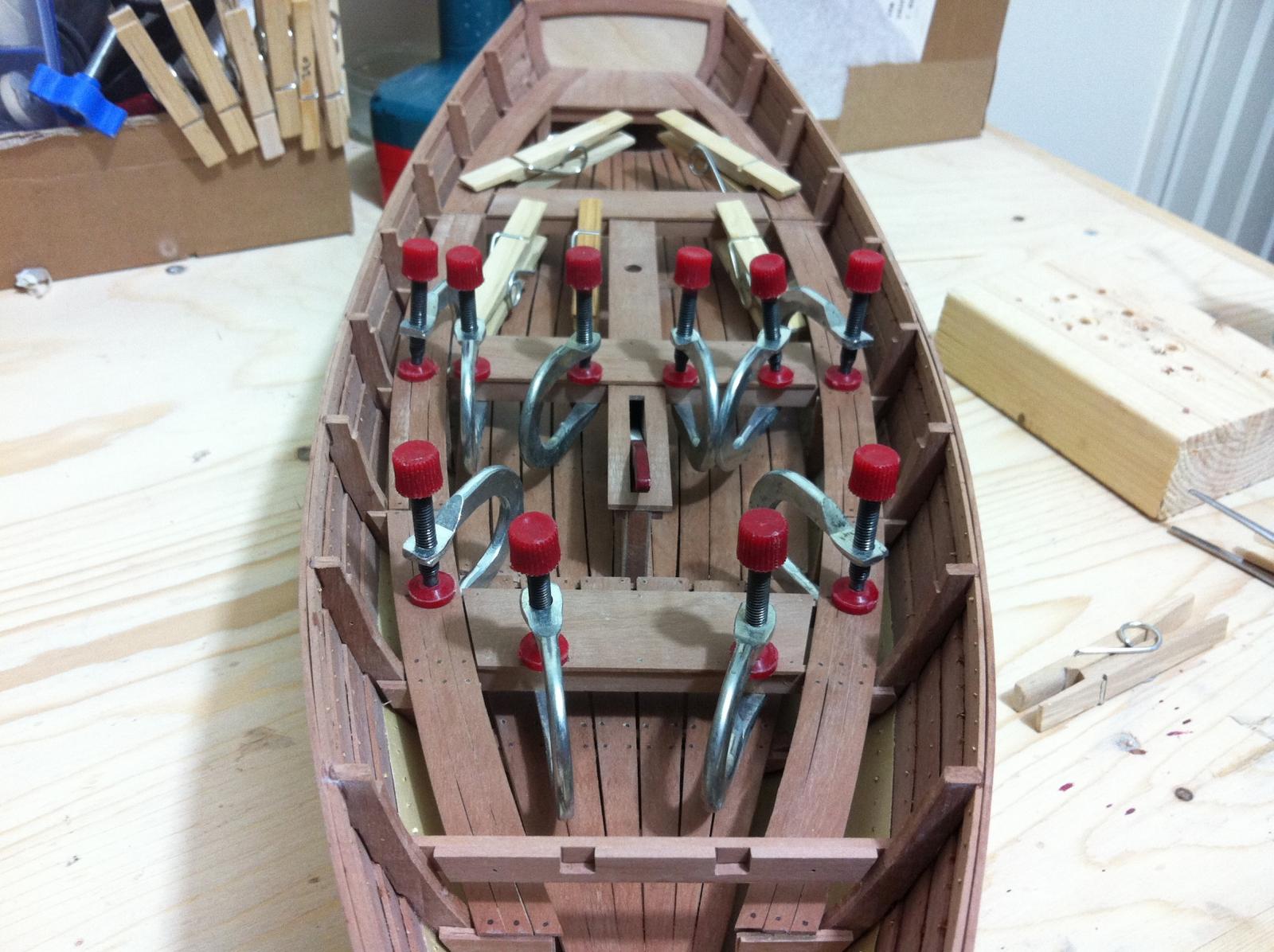
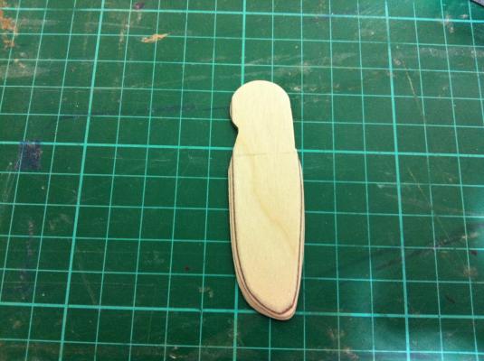
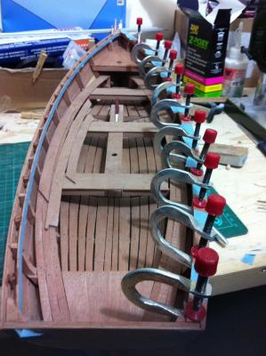
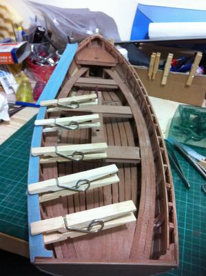
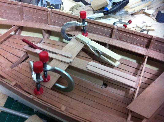
Dear all, thank you for the comments and likes. Life commitments again allowed very little work on the boat. I spent a good deal of time studying though and now I have in mind a rough outline of the rigging. I also decided I will make all metal work from scratch, read a bit about soldering and ordered some equipment and metals. There are just a few things that need to be made, the hinges, oarlocks, anchors and spar fittings but it should be a good start to metalwork. The rudder is pretty much ready, needs final assembly, hinges and painting. I also would like to install ropes to lower and raise the rudder blade. It looks more elegant this way! Also, I sanded the edges of the blade. I still have not decided on the tiler though. I also worked on the rub rails and here I hit a snug. The two pear wood strips I had saved are not wide enough. I used some lime strips just to have an idea of the fitting, really you can never have enough clamps!

- 253 replies
-
- 7
-
-
- ketkch
- gaff-rigged
- (and 1 more)
-
Congratulations Patrick! I count 2 sail boats, 1 Submarine and a tender, all wonderfully made. Symphony has reached home but really it was a great journey!
-
I just stole a few moments to check your progress Patrick, glad I did, the new photos are priceless. Fantastic work!
-
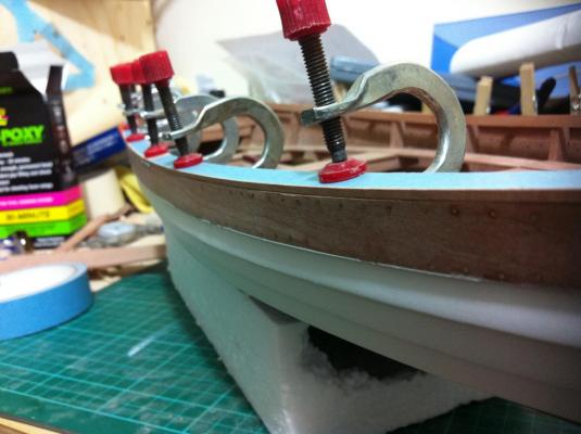
Indeed Patrick, the end is I think in sight. No really sure what the next boat will be, certainly scratch built though. Maybe a nice small fast schooner, the type a smuggler would use but this might be too big a bite. It would also be a 4 year project at least... The gunwales proved to be a mountain to climb and somehow I messed things up. I prepared all the parts and only the simple task of gluing was left and I managed to not align the segments properly. Epoxy is very unforgiving and I could not fix a very small gap at the bow. A shame really as everything was cut just right. Next the rub rails and then the big job of making the rudder
- 253 replies
-
- 10
-
-
- ketkch
- gaff-rigged
- (and 1 more)
-
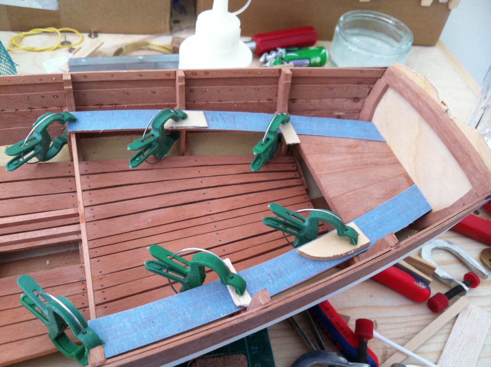
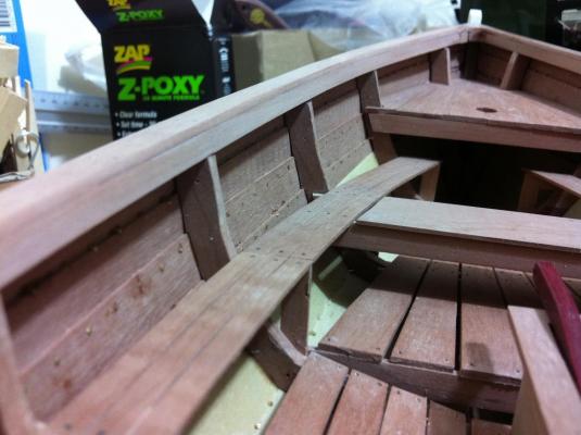
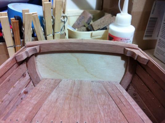
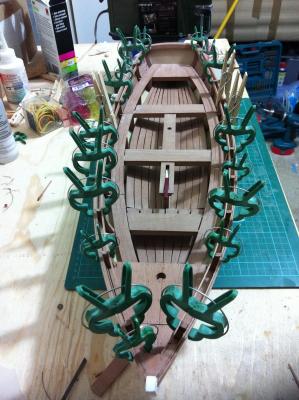
Dear Patrick and Michael thank you for your comments and continuing support. Indeed the problems have been sorted, the computer is running fine and the new 30 min epoxy (this Zpoxy brand) is absolutely brilliant. I fitted the breasthook, the transom brackets and the inner clamp. A small mistake will be fixed invisible later on, I did not have another strip to make again the part as somehow I managed to use both back up strips Next the small blocks were installed between the two clamps to strengthen the structure. This took quite a bit of work as each block was unique to fit each space Next it was time to fit the gunwales which actually has been so far an easy job. The pattern was easily cut with masking tape and a sharp razor. Lots of sanding is needed and then the rub rail to be fitted and painted but it already looks nice! I started thinking about the oars and also the rudder which will certainly will be a big job. The mast fittings are giving me trouble and more research is needed. Still lots of work left!

- 253 replies
-
- 9
-
-
- ketkch
- gaff-rigged
- (and 1 more)
-
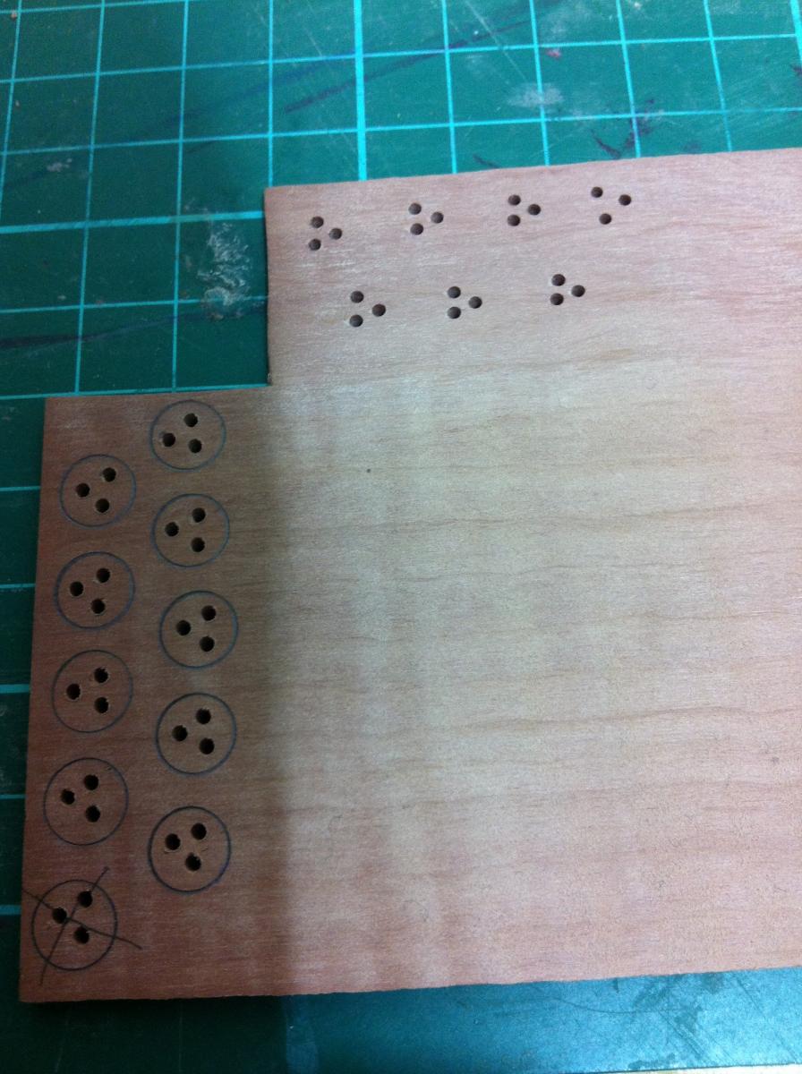
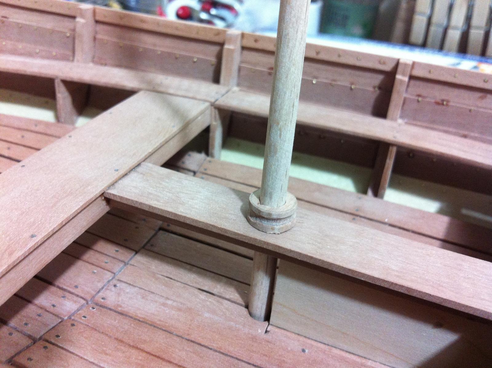
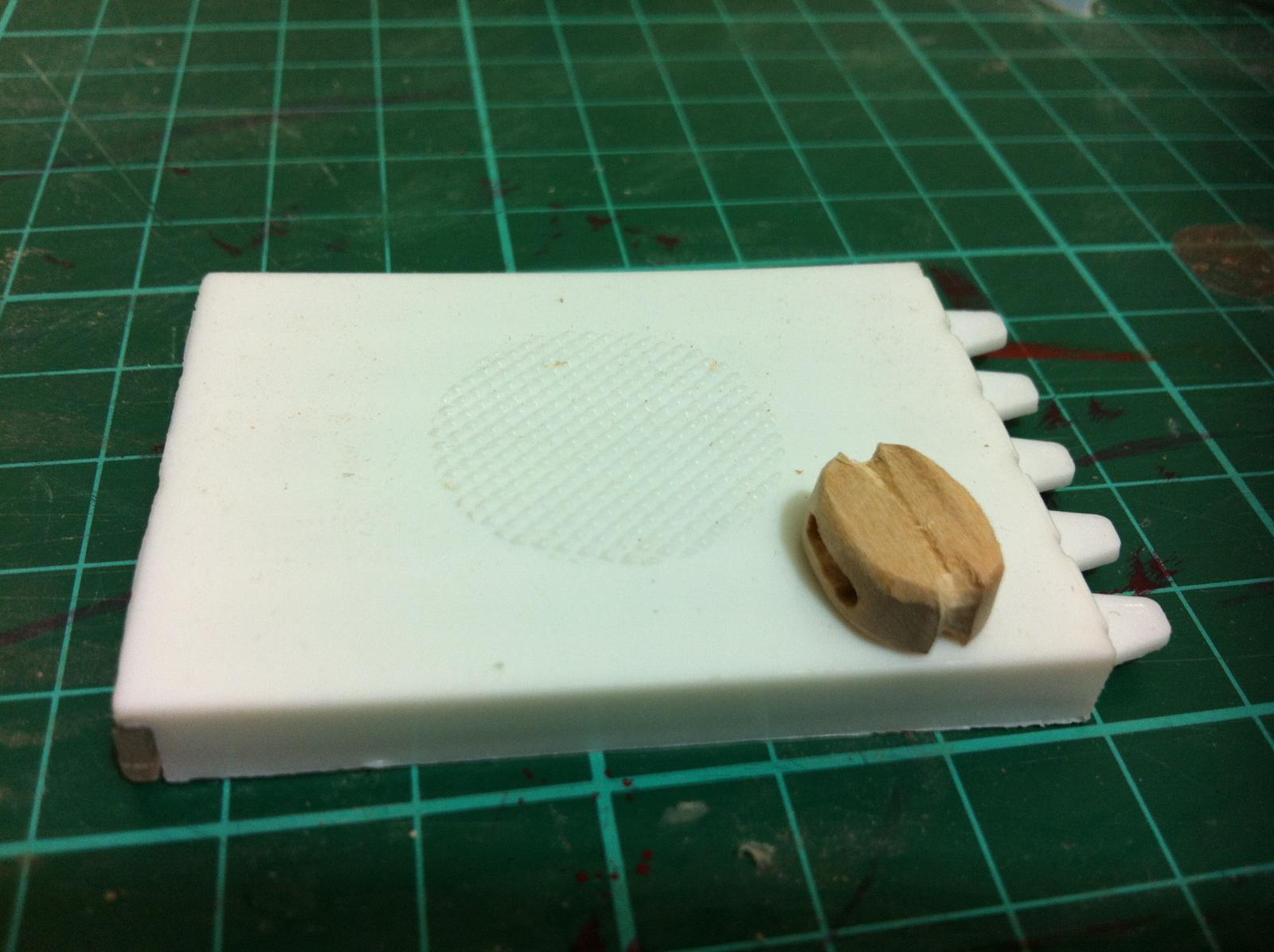
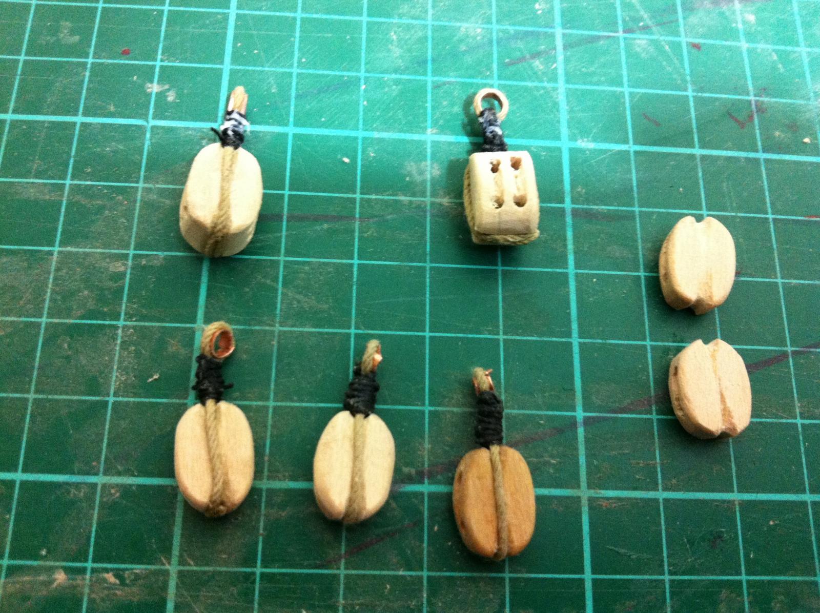
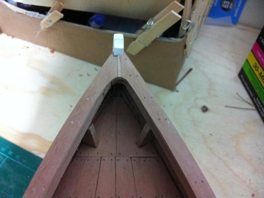
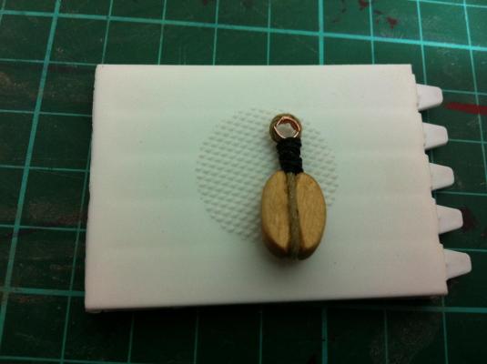
SInce the last post progress slowed almost to a halt due to a number of near disasters. I first had a serious computer problem and trying to get the system working again I realised all the CAD files that it took me months to create were lost. Then I realised I did not have a back up! Although they have served their purpose I would have hated to lose these. To get the system running again I had to upgrade to Win 10 and thankfully, somehow they reappeared. The second problem was an epoxy one. I bought a new epoxy glue which proved rubbish, either not curing and remaining tacky or curing rubbery with no strength at all. Again, luckily I realised this early but still I had to remove some pieces and scrape and sand to remove the uncured epoxy. I am still waiting for the new epoxy to be delivered. The deck is finished, glued with the rubbish epoxy but still seems to be glued pretty well. I did not expect this to be difficult but actually it took a very long time and a lot of wasted timber to get the deck to fit right. Of course, the masts need some wedges to make sure they are snag against the mast partner. There will be some canvas covering the base of the mast and the wedges. (Not really necessary but I saw this in another boat and liked it) Since I could not proceed with no epoxy I thought I could work on the rigging. I still am not sure how it should be arranged or even of the rope sizes but I would like to use traditional wooden blocks. I followed mostly the tutorials of Dan Vadas with a few modifications and I think they came out fine. The most difficult think by far was actually the rope work. The darker block has a coat of Tung oil which I am not sure is actually needed. I still need to think how the rigging will be arranged and how to make the mast and deck fittings etc. I may need to make some things out of metal which means acquiring new skills or buy them ready. I would like though to scratch build everything if possible.


- 253 replies
-
- 10
-
-
- ketkch
- gaff-rigged
- (and 1 more)
-
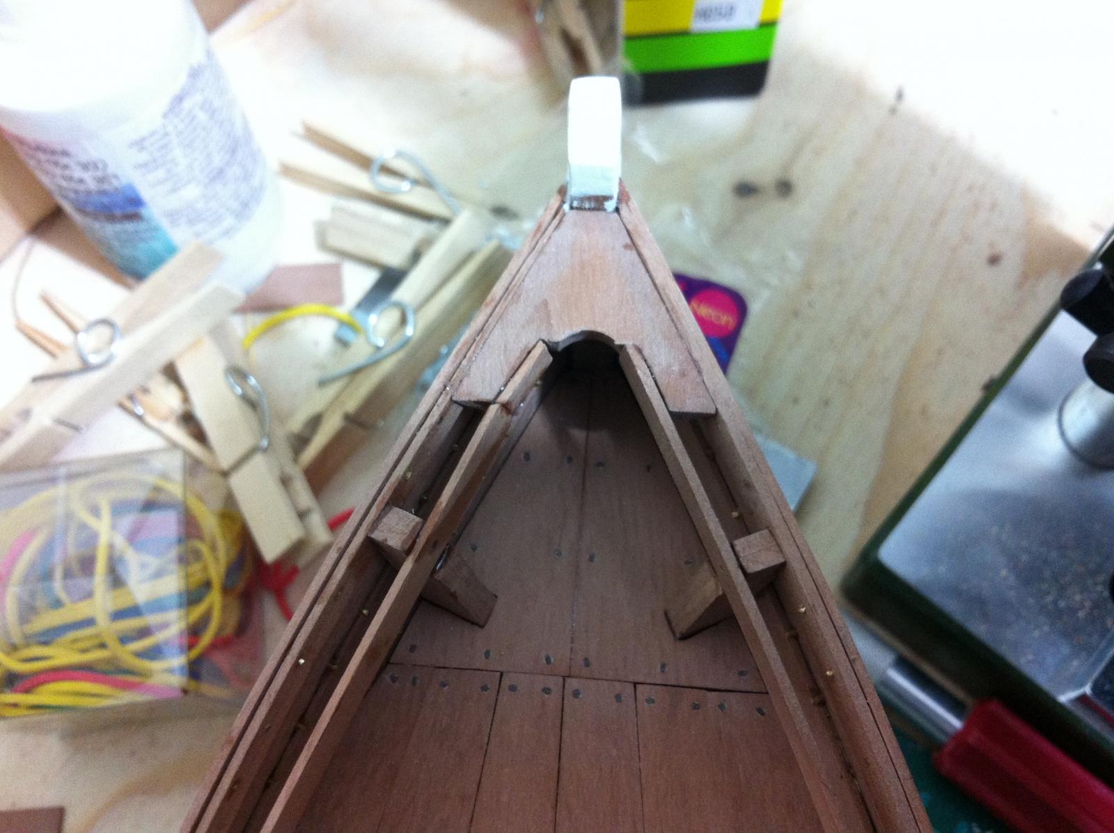
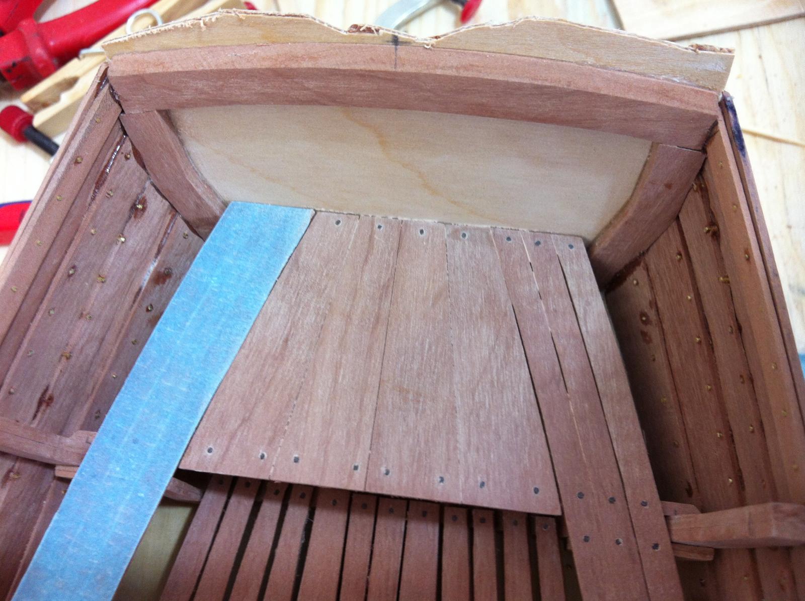
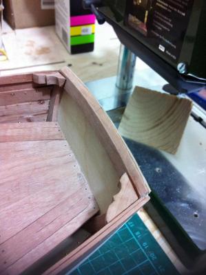
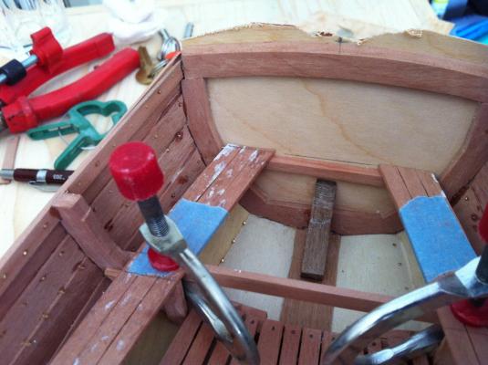
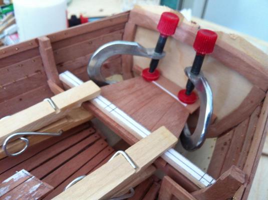
Dear Patrick, John and Bob and to all who hit the like button thank you, your support is much appreciated. I finished the last few components of the foredeck support and epoxied everything in place. I am very happy with the result, it is very solid and completely flat and certainly would work in the full size boat. I also glued the step for the main mast which was a rather fiddly job but came out well centered. I also made the breasthook which is notched to accept the two inner clamps. I started work on the deck and I thought that if a place a lot of small pieces of tape I would get roughly the shape of the deck. This worked quite well and the fore part of the deck which is the most difficult came out fine. Hopefully tomorrow I ll finish the deck and install the inner clamp and gunwale and then it will be time for the rigging and fittings.
- 253 replies
-
- 8
-
-
- ketkch
- gaff-rigged
- (and 1 more)
-
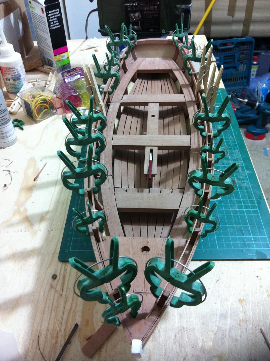
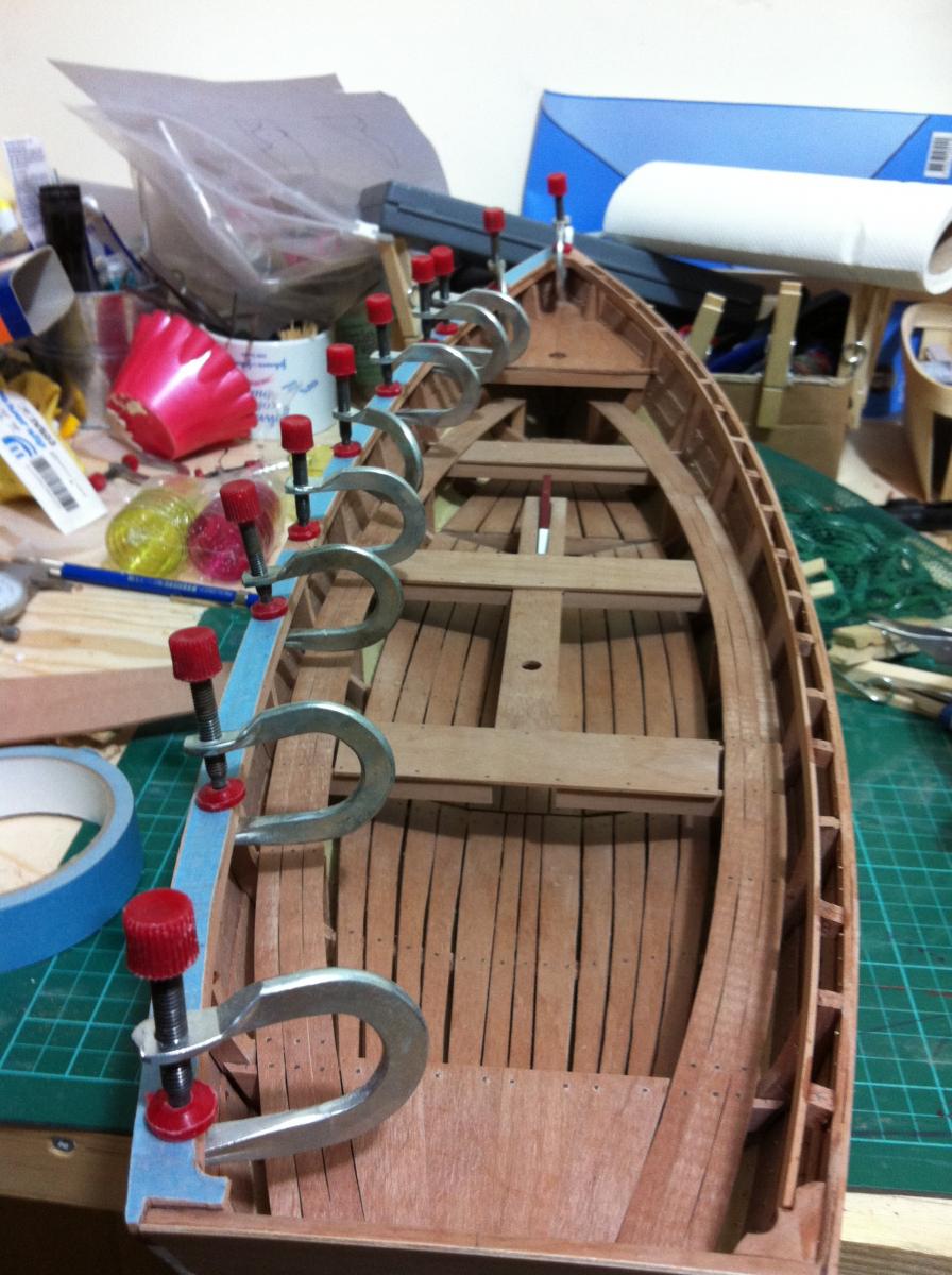
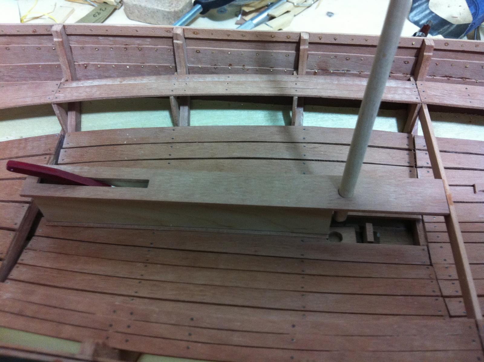
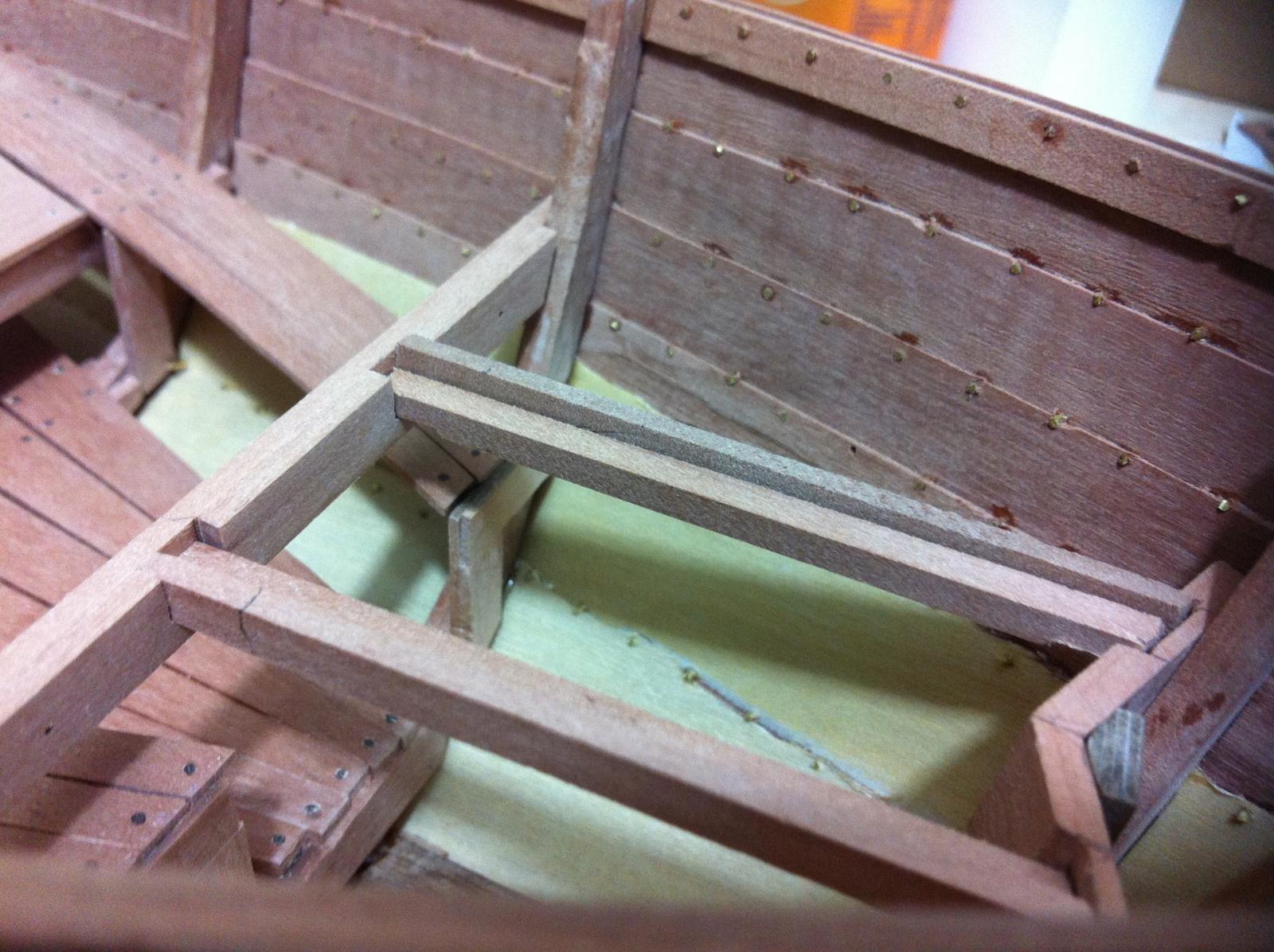
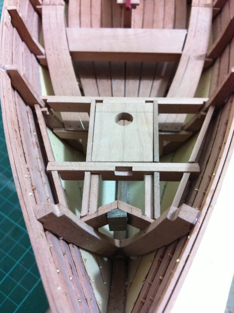
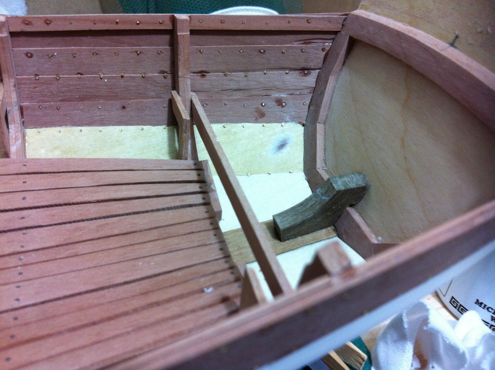
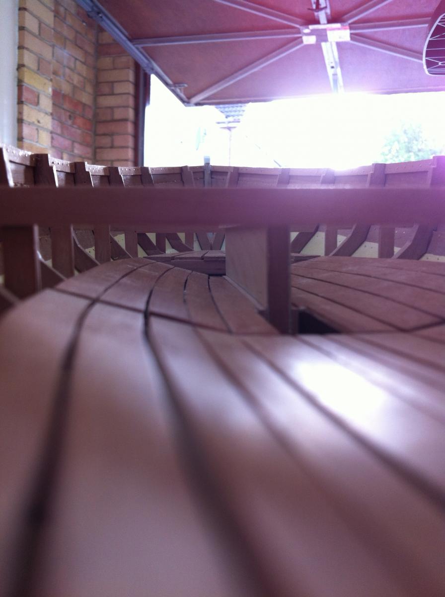
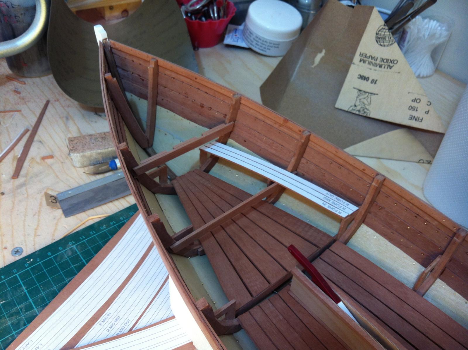
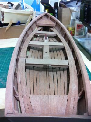
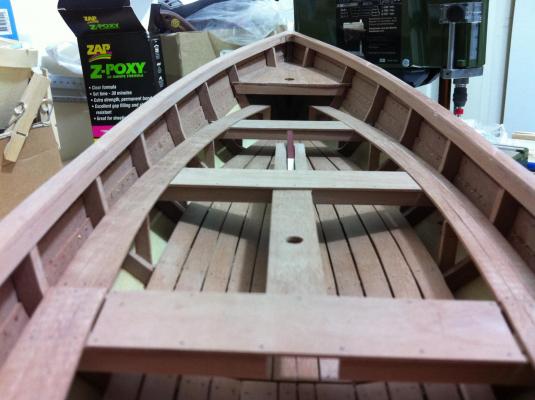
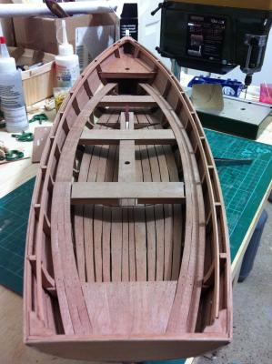
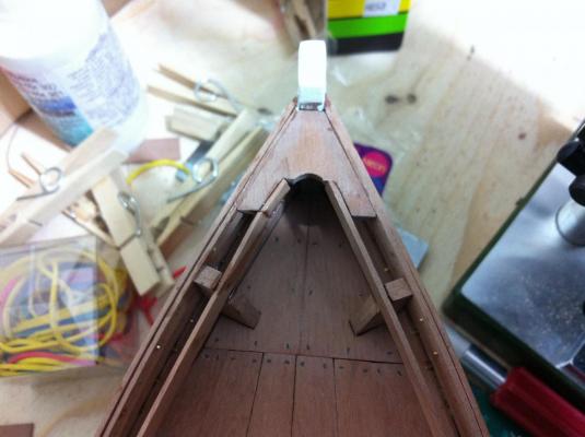
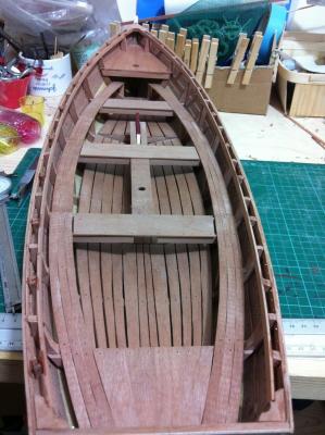
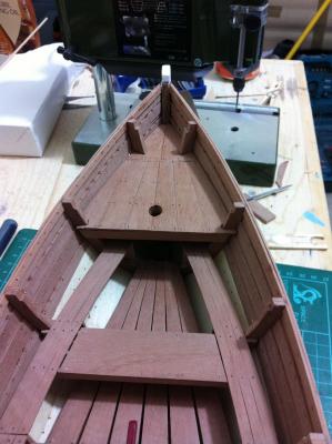
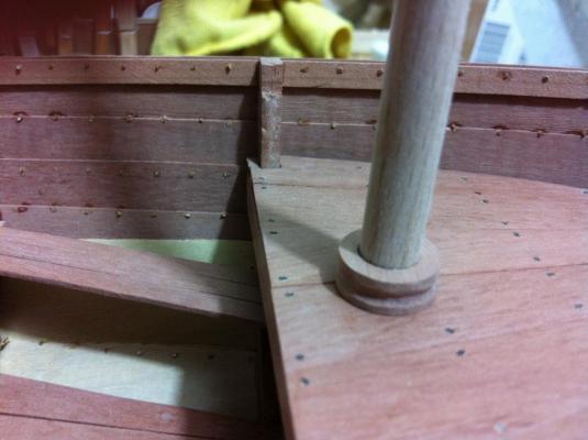
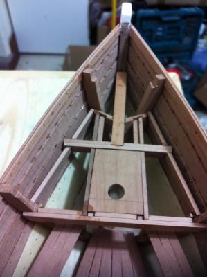
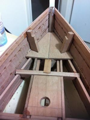
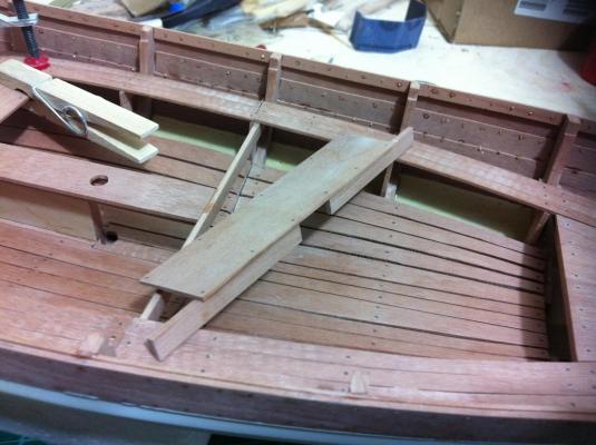
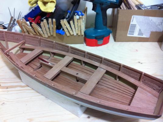
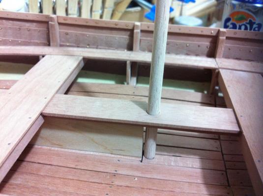
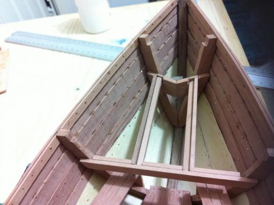
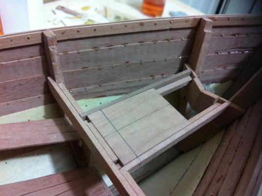
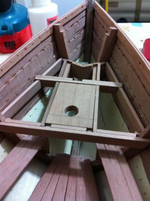
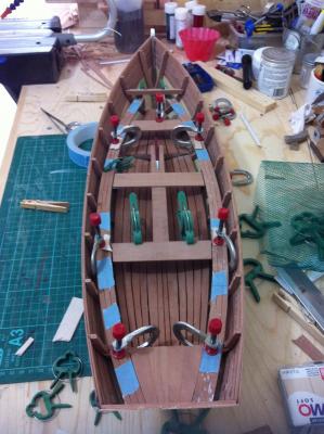
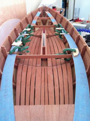
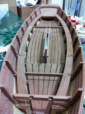
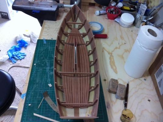
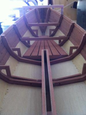
After a long break due to summer vacations I started again work on the boat. I finished and glued the mizzen mast step and the center board case cap that supports the middle thwart and also acts as mast partner. I also made and glued the two small boards to complete the floor. Next the thwarts were installed, I copied exactly the way the american team used cross beams secured to the frames and the side benches although later on I realised that I positioned the thwart aft of frame 6 instead of forward but no harm done. I must say I quite like the result! Next it was time to install the main mast and most importantly the small deck which I think will add a lot to the boat. This proved challenging mainly due to the cant frames which increased a lot the complexity of the built. Still a lot left to be done but I am looking forward to see the deck completed.


- 253 replies
-
- 10
-
-
- ketkch
- gaff-rigged
- (and 1 more)
-
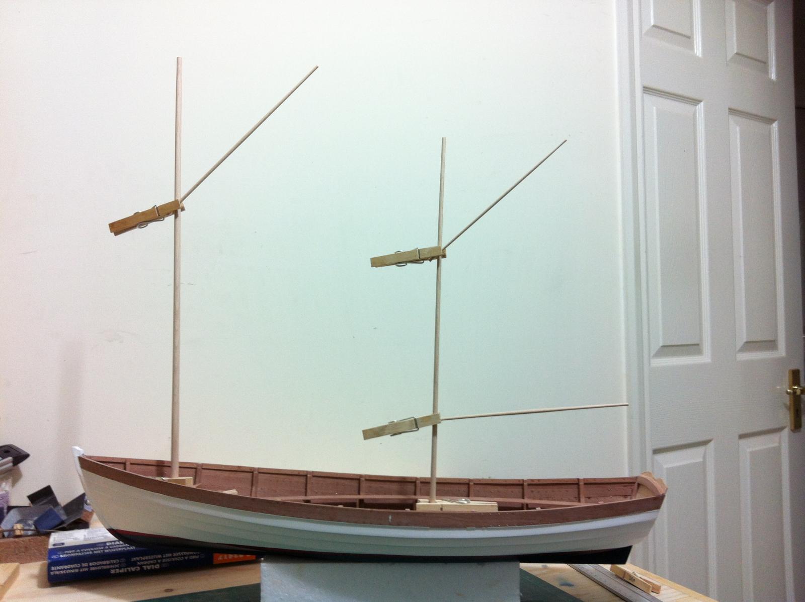
I think it looks fine! the gaff and boom seem a little flimsy to me but they are accurately scaled down from the plans

- 253 replies
-
- 7
-
-
- ketkch
- gaff-rigged
- (and 1 more)
-
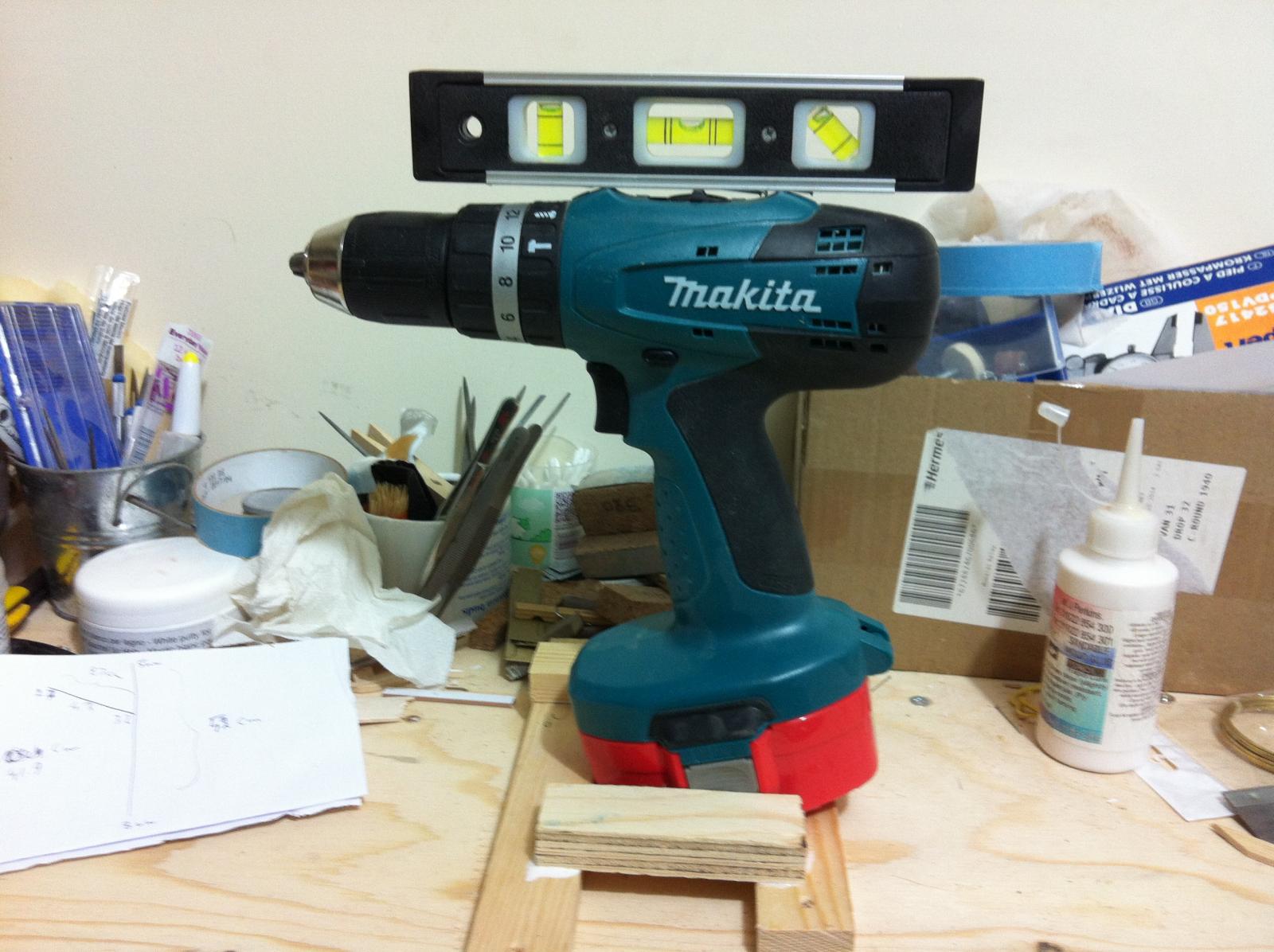
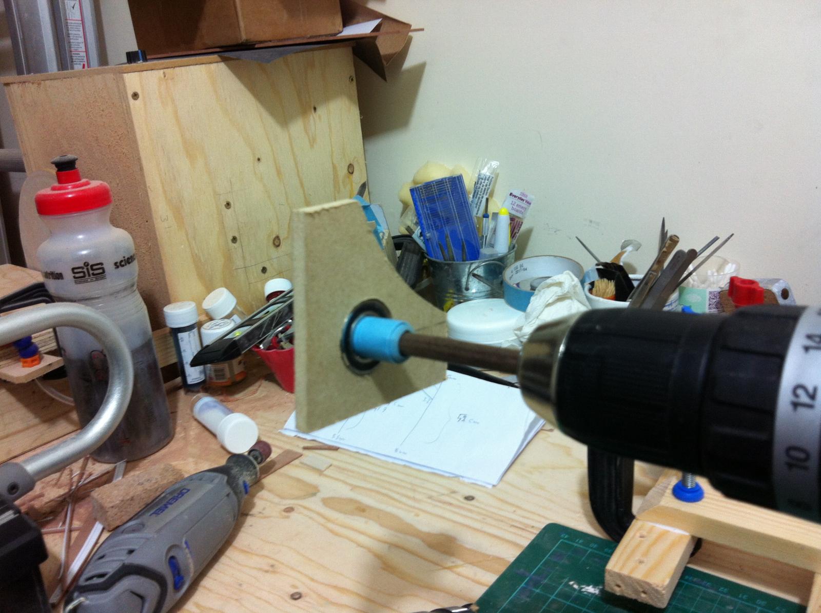
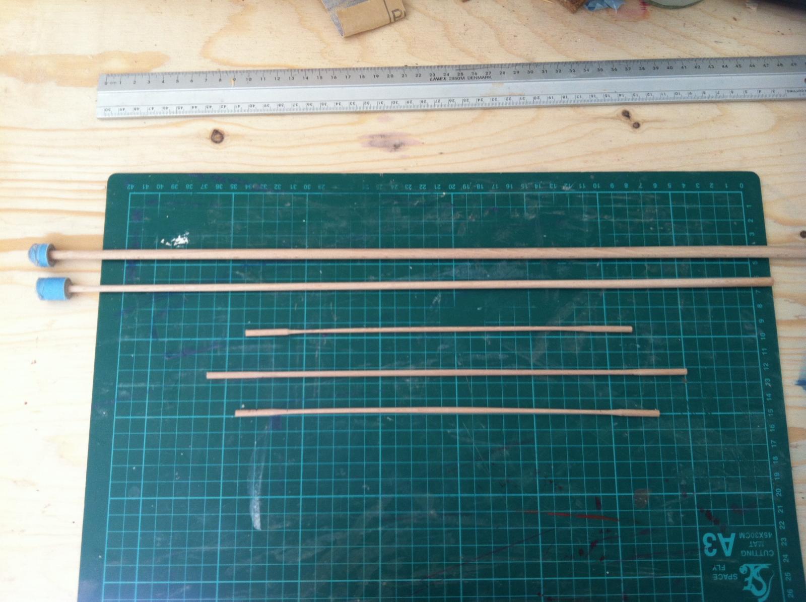
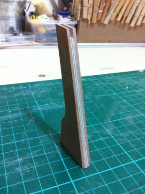
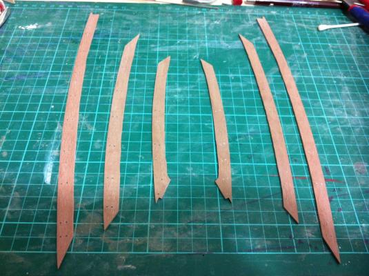
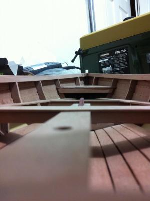
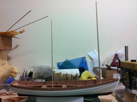
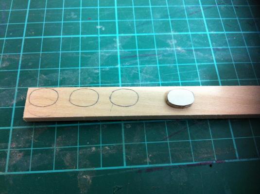
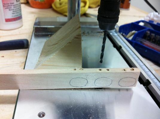
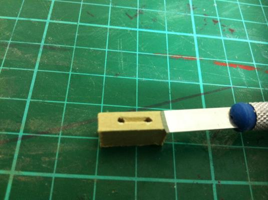
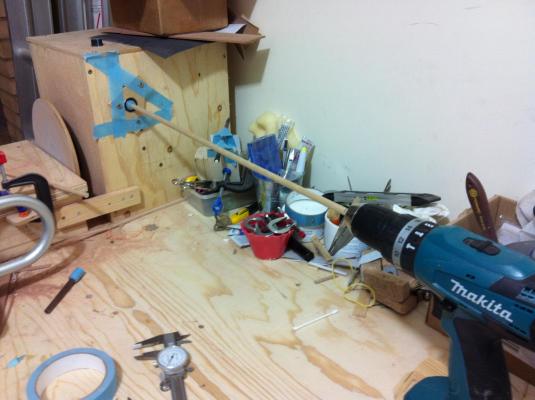
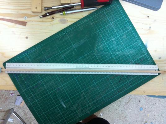
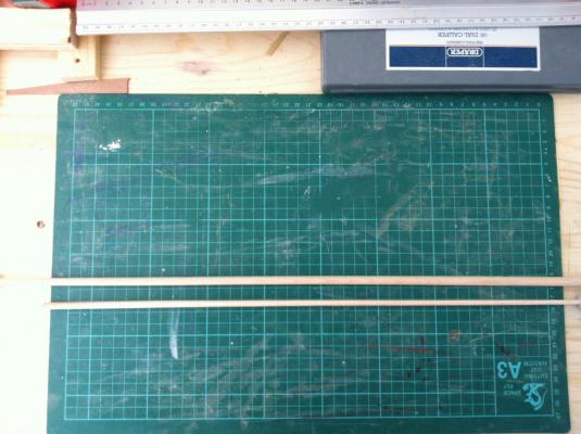
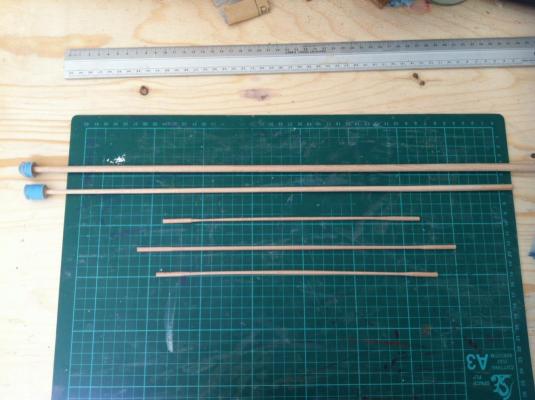
Patrick, John and everyone hitting the like button, thank you for your support. I decided to make the masts, booms and gaffs. I used walnut in the past but it is too hard and not readily available at this time. I ordered both beach and birch dowels, I did not like birch but I found beech to be a lovely wood. It has little grain but open pores and visible growth rings, this however does not matter at a scale 1:12. The masts and booms are tapered so a power tool and sand paper would be needed. From previous experience though, this set up is too unstable and tiring to use. I attempted to construct a simple jig to support the dowel First I made a support for the drill to keep it horizontal Then I cut a hole in a scrap piece of mdf and inserted a bearing Then aligned everything and secured the piece of mdf to the disc sander. Masking tape around the end of the dowel ensures it is snag and centered in the bearing. This setting worked beautifully, I got the main mast tapered and sanded to 400 grit in no time. The next pic shows the gradual taper from 8 mm to 5.5 mm Then the mizen and all the rest. There is extra wood in either end in all pieces but I will trim it later on, after I do some test fitting. In Tad's plans the mizen does not have a boom but the american team do have one. For the time I will follow the original plans but I might add a boom later on.


- 253 replies
-
- 7
-
-
- ketkch
- gaff-rigged
- (and 1 more)
-
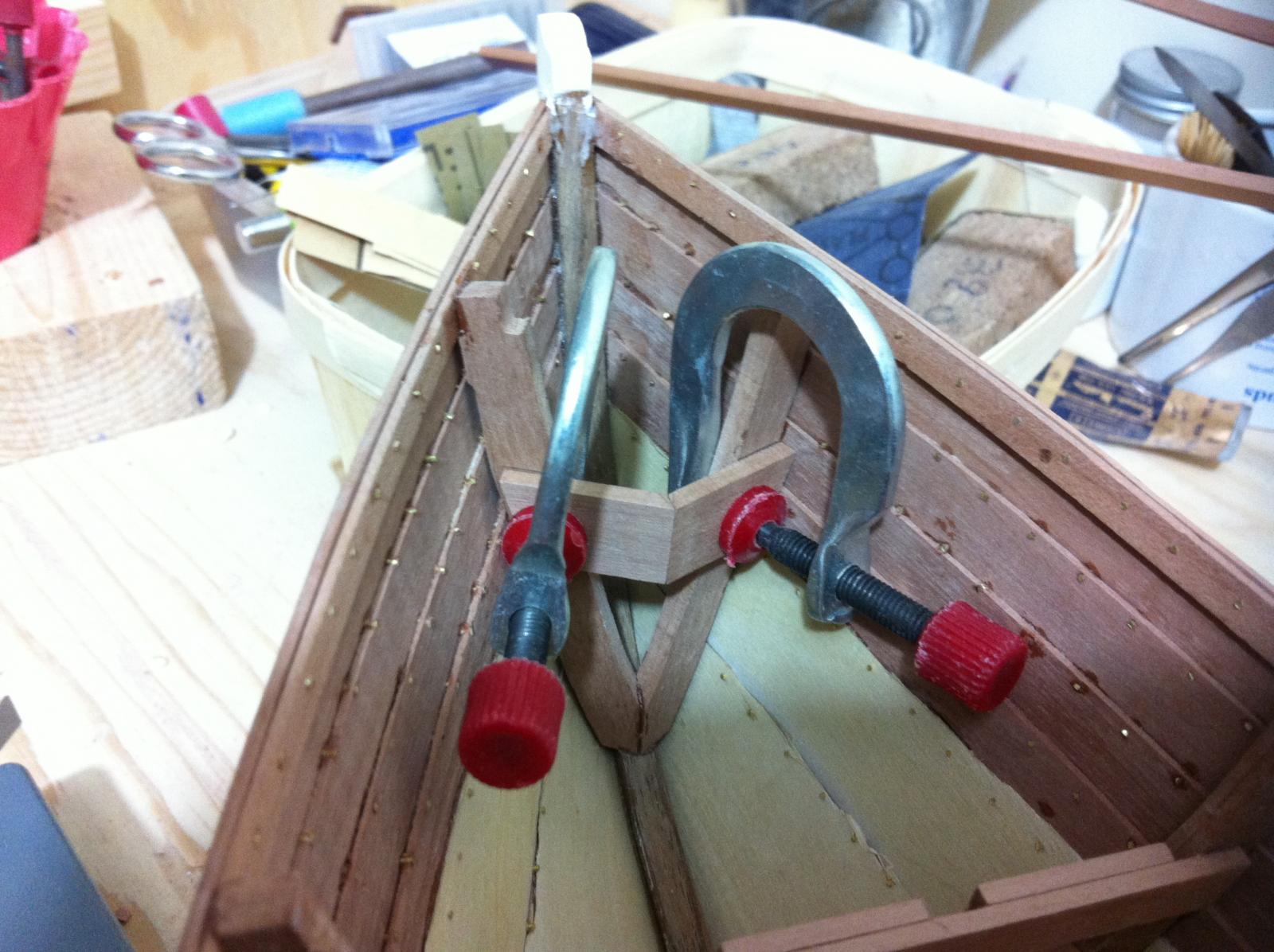
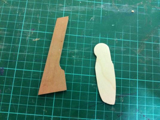
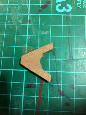
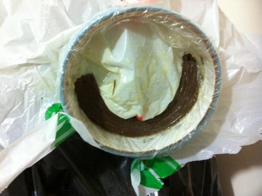
I somehow found time to get a large chunk of work done. The transom knee laminate came out fine, a solid piece of timber. No way I will lose my transom in heavy seas now! Test fitting all side benches and thwarts Then the transom thwart support went in, appropriately bevelled Then the transom thwart and the aft side benches I did of course forget the tree nails for the transom thwart which thankfully were easy to install later. Then the rest of the benches were tree nailed and installed To install the rest of the thwarts I will need to install the mast step for the mizen. Soon it will be time to start work on the small deck.


- 253 replies
-
- 8
-
-
- ketkch
- gaff-rigged
- (and 1 more)
-
Patrick, it seems to me that your beautiful cupboard needs a model boat to sit on top, preferably one in a bottle. This is fantastic work!
-
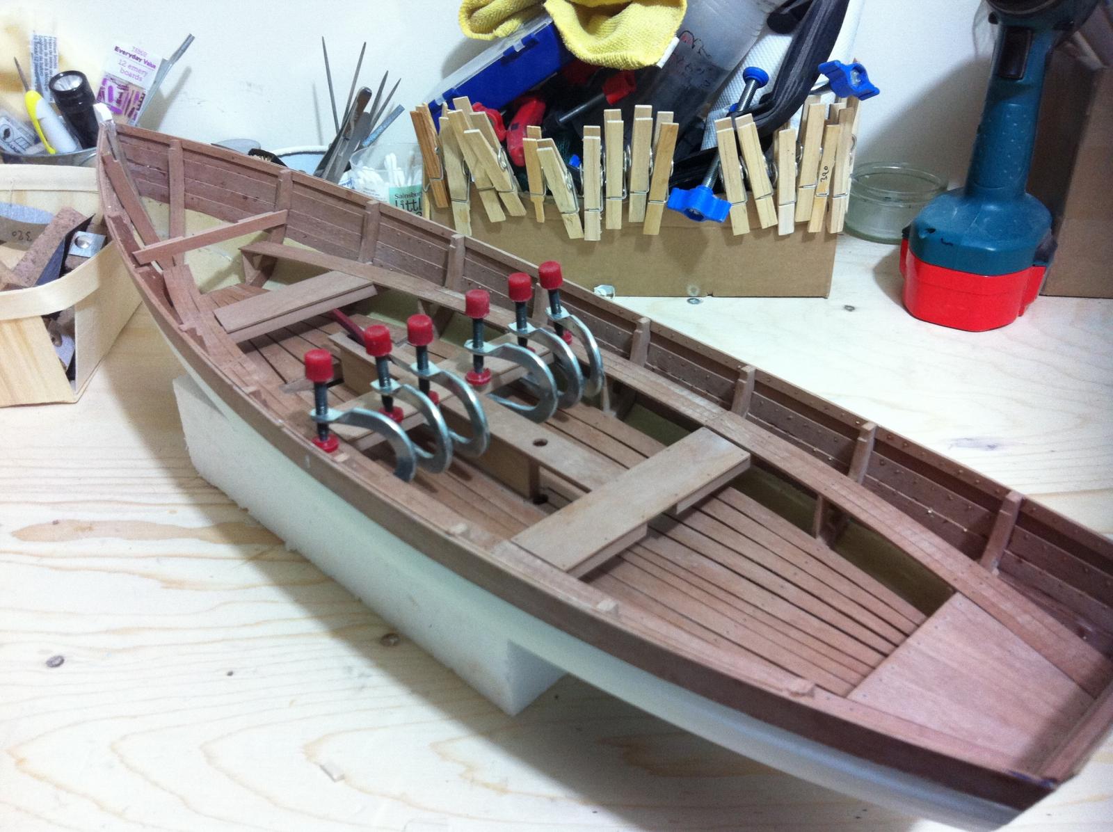
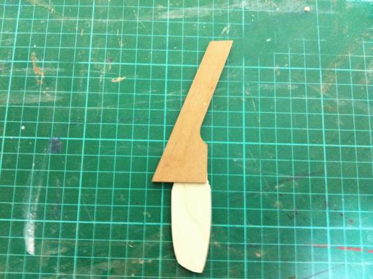
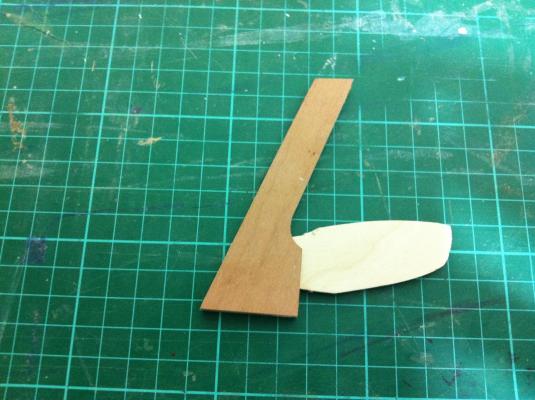
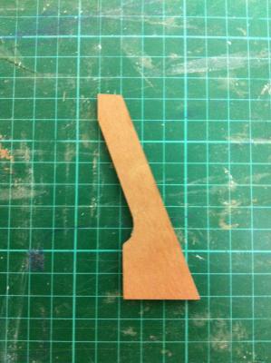
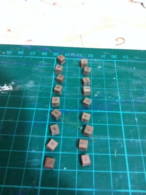
Dear Ben, thank you for your very nice words and your suggestions, I really try to approach the built as if I was building the real thing and the large scale helps I think a lot. Certainly the boat will be in a cradle, it would break my heart to drill holes! But of course the scale creates problems e.g. taking pictures or thinking about how to display. Dear Patrick, when I read your question I knew there was trouble ahead and more uncharted waters to navigate. Displaying the boat in the shipyard's workshop is a great idea and making all the machinery, logs, sawn timber etc would be great fun but the diorama would probably be too big for my house, considering the boat is 60 cm long. Still it could be done. Another option could be with crew rowing. But either option would need figures so for the last few days I was researching how figures are made from scratch. I do not have a single artistic cell in my body but I will give it a try, although with 1:12 scale the figures will need a lot of detail which would be lost in smaller figures. More updates on this in due course! Back to the boat, with such classy company in the forum, the Butterfly Explorer absolutely needed a few hundred treenails. So here they are. I apologise for the quality of the pics, it is difficult to take good pictures with the mobile phone camera. I also continued work on the benches which surprisingly need a lot of fiddling to fit properly At this time I need to install to the transom the support for the aft bench but I realised I have forgotten to install the transom knee! This is a major structural element and in the plans it is a laminate (The american team again made it from solid wood) The shape was actually very easy to determine and my jig this time was much simpler!

- 253 replies
-
- 4
-
-
- ketkch
- gaff-rigged
- (and 1 more)
-
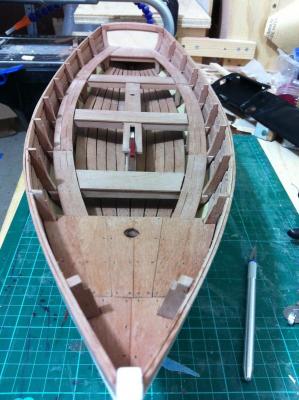
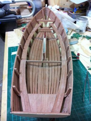
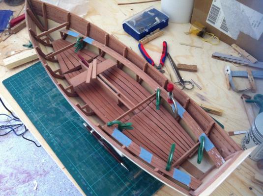
Dear Patrick I have not given it any serious thought, any suggestions welcome. I would like to make a few artefacts, life preservers, anchors, a chest (I have wanted to make a chest for very long) but I am concerned that the huge scale 1:12 may be a problem. Or it could make things easier! Letting the imagination go wild takes me to figures rowing but this is beyond my skills. Basically the answer is no! The floor boards and the centerboard are now installed. The photos are not very good but the boat is really too large for the iphone camera I could not resist a small comparison... I started work on the side benches that also support the thwarts. Very careful cuttings with the scroll saw were needed but the Dremel saw came through. Test fitting shows only minimal sanding is needed. With the right side bench roughly in place, I only now realise how large actually the boat is. There is lots of room and storage space. If built properly (the plans also call for fibreglass sheathing over the plywood bottom) this is a super strong design. I just realised I forgot to drill holes in the boards and insert nails. This now needs some thought.

- 253 replies
-
- 7
-
-
- ketkch
- gaff-rigged
- (and 1 more)
-
Thank you Michel, the design helps as it is very fun boat to build. Ben I think you are right, the scale is somewhat lost in the photo, taken of course entirely by chance. I opened the slot a bit more so now the centerboard fits and I managed not to destroy the paint. I continued to work on the floor boards today as I find it a very enjoyable task. However, the aft side boards are very difficult to get right as they are curved and concave, with decreasing widths. Also, pear wood is hard and sands slowly. I think I got it reasonably close though.
- 253 replies
-
- 7
-
-
- ketkch
- gaff-rigged
- (and 1 more)
-
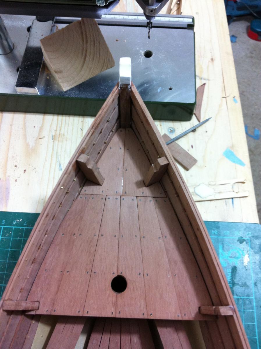
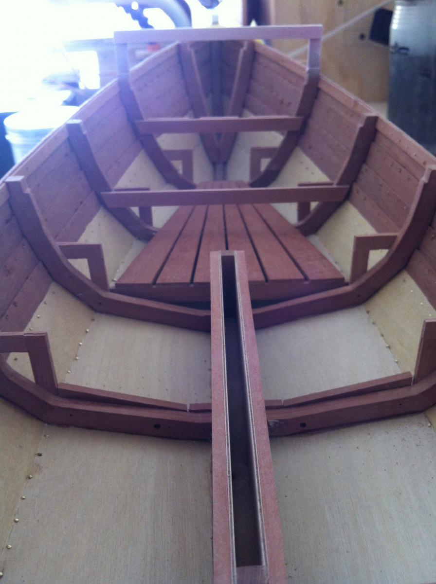
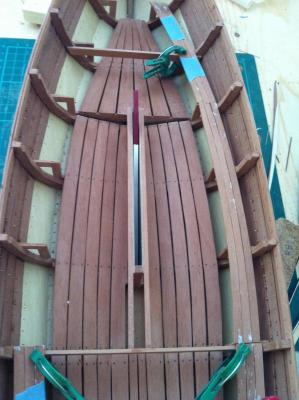
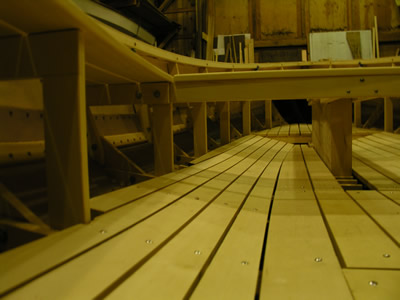
All floor boards are cut! I installed the fore deck boards, 2 coats of renaissance wax were applied. I also finished painting the centerboard as it needs to be installed before the floor as the axle will be inaccessible. Before adding varnish, I tested the fit again. Yes, it does not fit through the keel slot! With all the coats of primer/paint it is now thicker. I will need to open the keel slot more risking damage to the paint work.

- 253 replies
-
- 5
-
-
- ketkch
- gaff-rigged
- (and 1 more)
-
Patrick this is very nice. That engine, terrific work! I must say that fruit and boats actually go well together, somehow your photos always bring to my mind the National Gallery in London which is one of my favourite spots. Looking forward for the rest of the journey Vaddoc
-
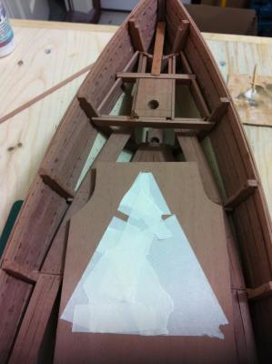
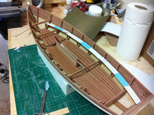
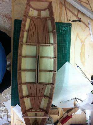
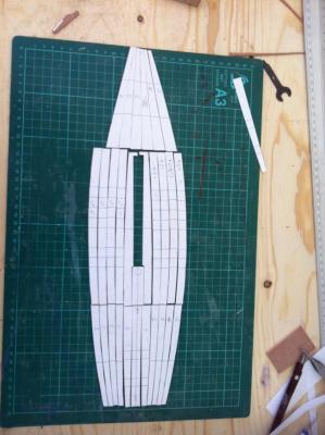
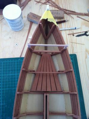
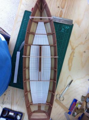
Patrick, your support is very much appreciated, I just wish I had the skill to produce the immaculate models I see in the forum. Baby steps... A very quick update, I did a bit of work on the floor boards and laid paper patterns and immediately the boat interior took shape. Before I cut and install these though, the mast steps need to be prepared and glued in place. The pattern of the individual planks is (more or less) completed, I intend to have a very narrow space between the planks. The CA glue I used has produced some stains on the inside of the hull, I managed to scrape off the largest ones. I tested nail varnish remover but it does not work well so I guess I need to tolerate a few minor stains.
- 253 replies
-
- 5
-
-
- ketkch
- gaff-rigged
- (and 1 more)
-
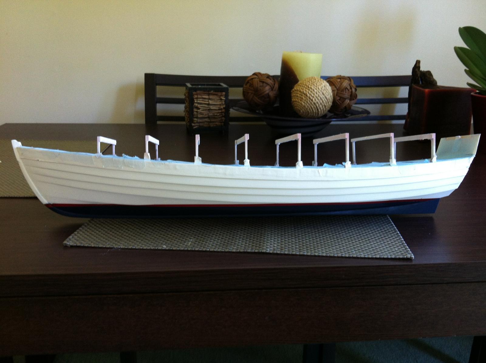
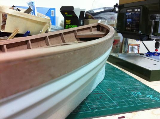
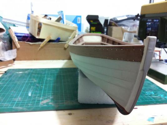
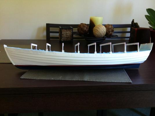
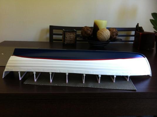
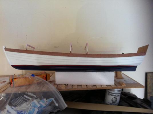
Thank you all, it sure is a huge relief to have completed this stage. Patrick and Ben, the admiral compromised with satin finish which actually came out more on the matt side so all is good Mike, you are right, I did some testing with tapes and indeed Tamiya is best, there is a discussion in the forum under "comparison of masking tapes" and there is also valuable contribution from others. The painting job is not as good as I would have wanted mainly due to my inexperience but also because with the little one now in the house there is limited time to complete a task. Still, it is done and it was a mountain to climb. I brushed 2 coats of humbrol satin enamel varnish and somehow I managed to use acrylic thinner to clean the brush. Thankfully the paint job seems not to be affected but I had to throw away the rest of the varnish as there was some contamination and precipitation. I removed the many layers of masking tape and cut some of the frame supports. I also trimmed all the rivets on the inside of the hull. I think that from very far away it looks quite similar to the american team's boat! Next, to paint and install the centerboard and then probably the floor boards.

- 253 replies
-
- 11
-
-
- ketkch
- gaff-rigged
- (and 1 more)