Check out our new MSW Sponsor Innocraftsman
×


rlb
-
Posts
655 -
Joined
-
Last visited
Content Type
Profiles
Forums
Gallery
Events
Everything posted by rlb
-
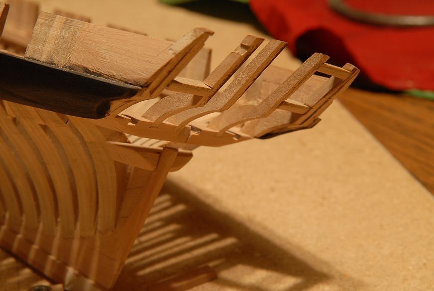
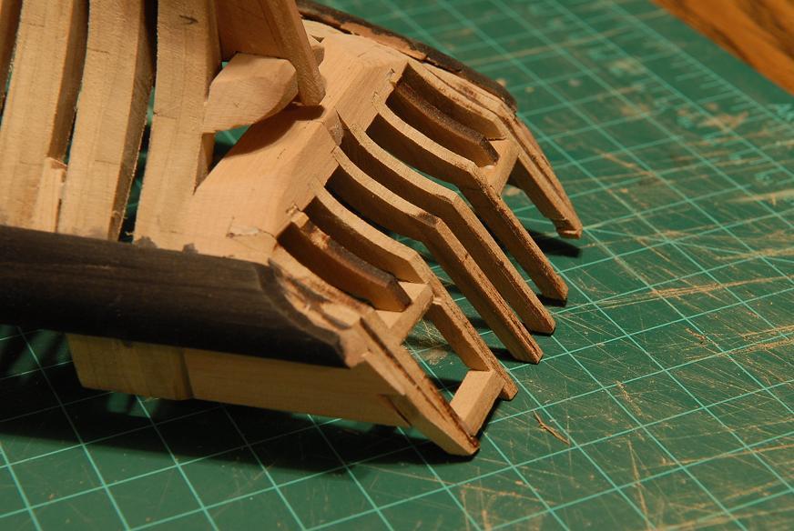
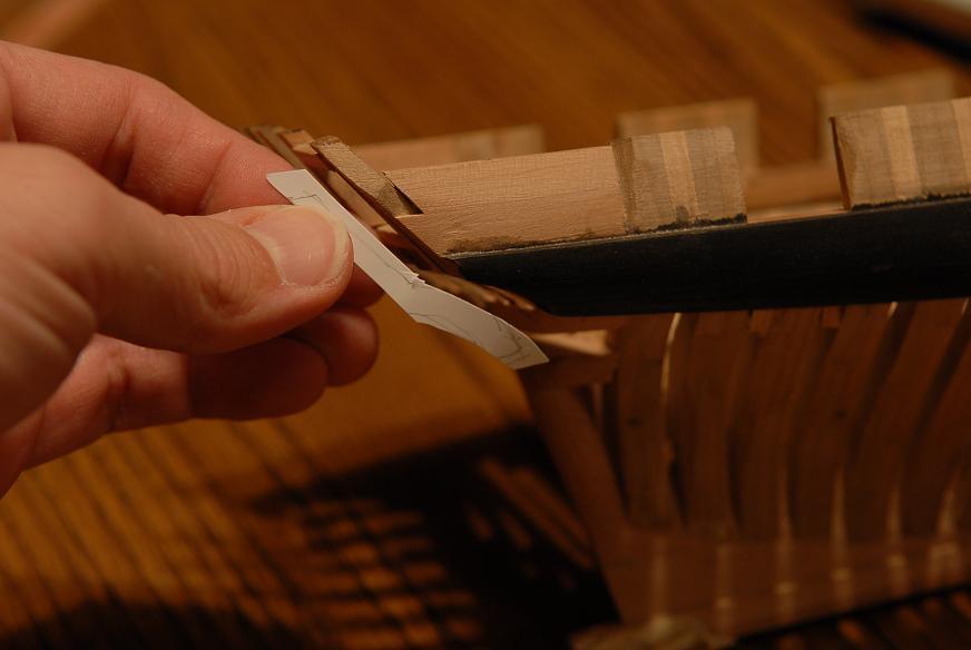
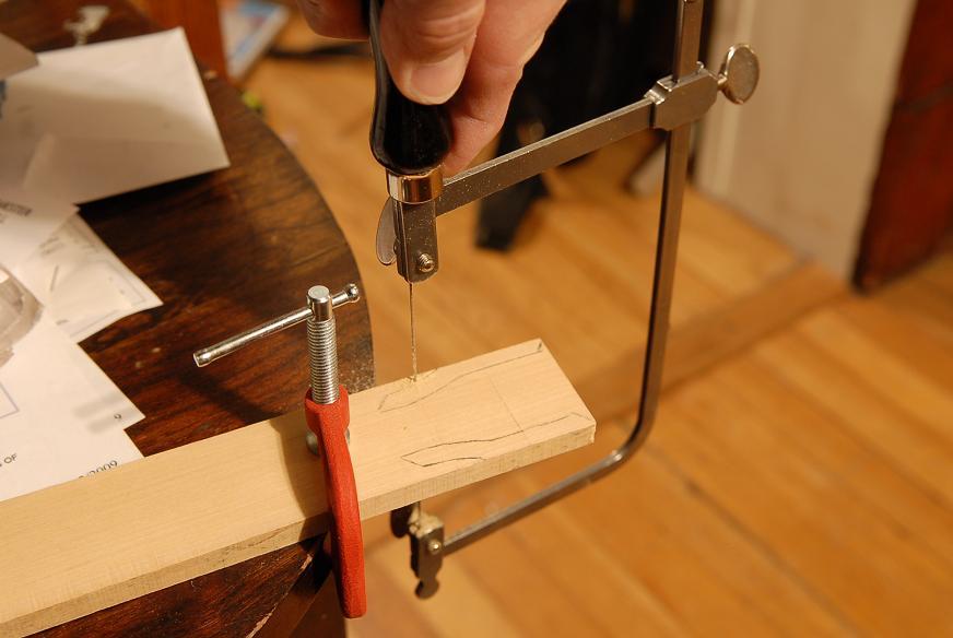
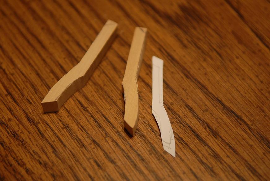
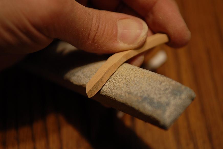
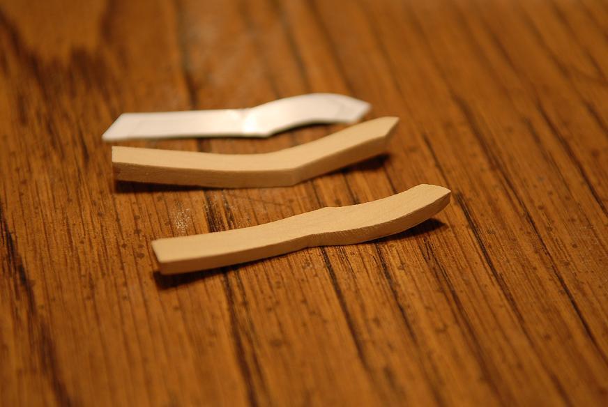
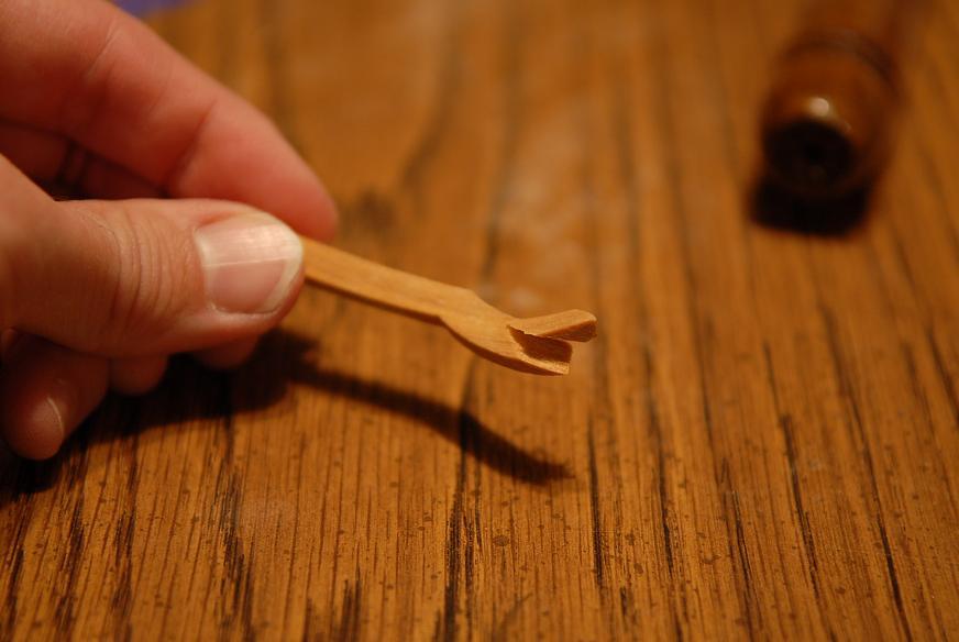
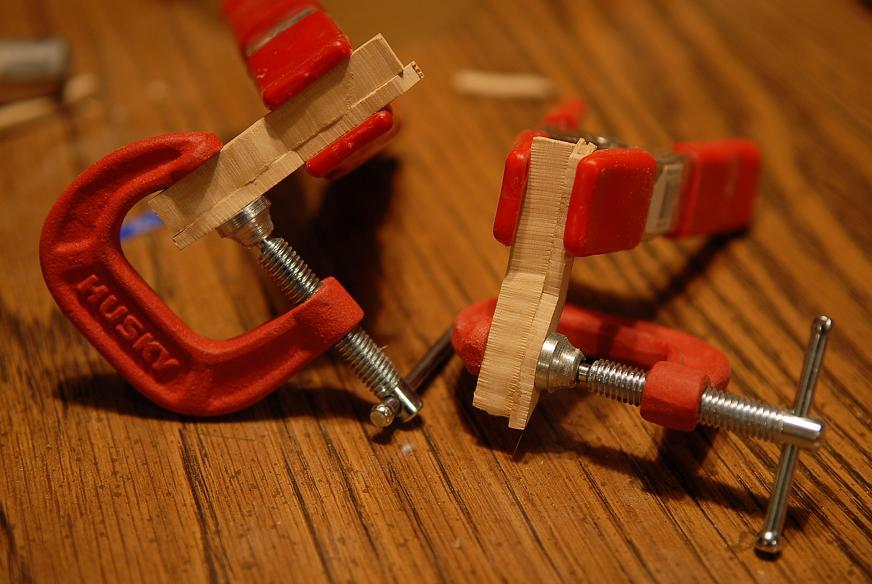
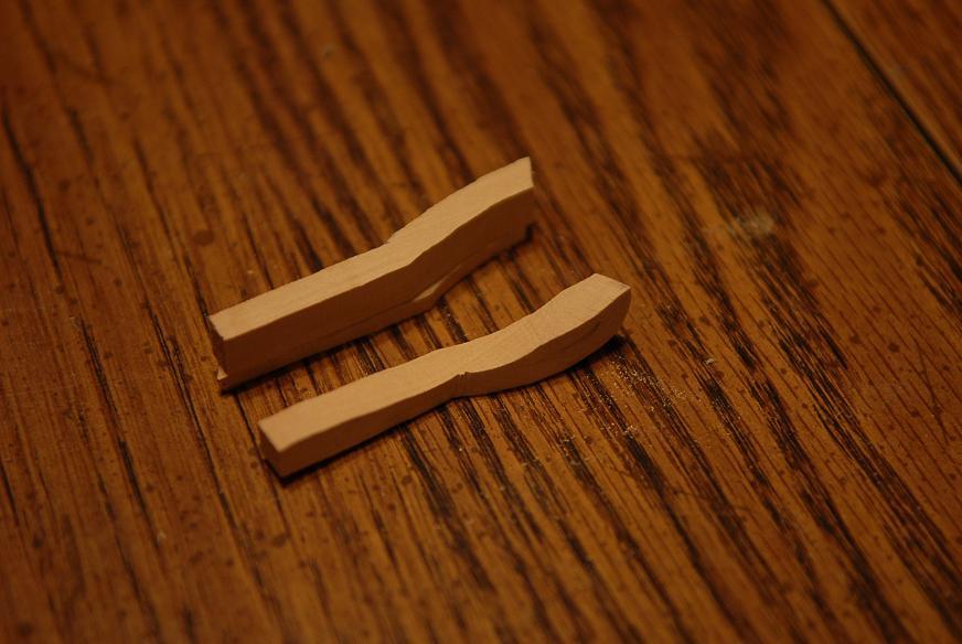
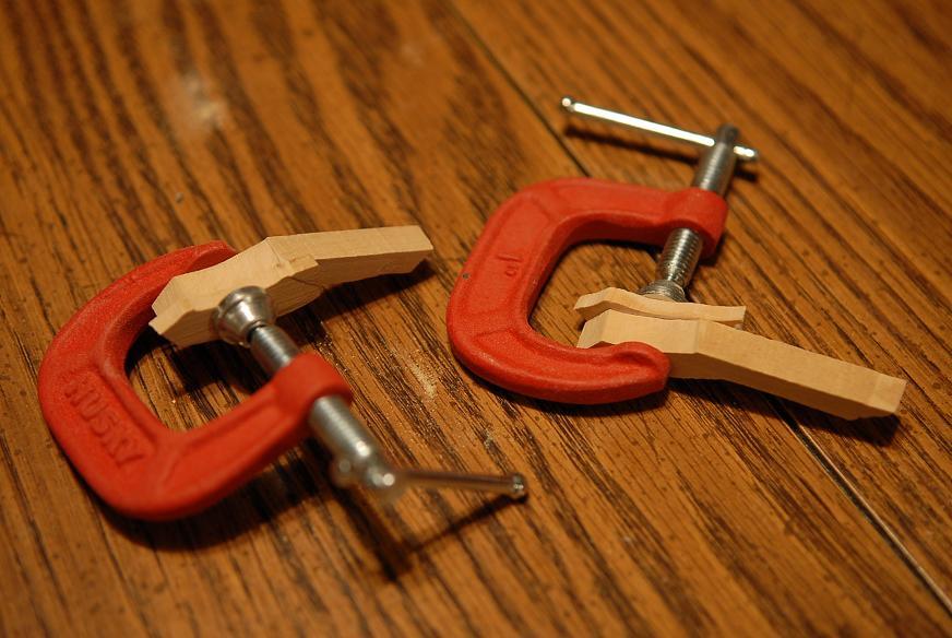
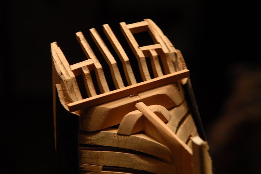
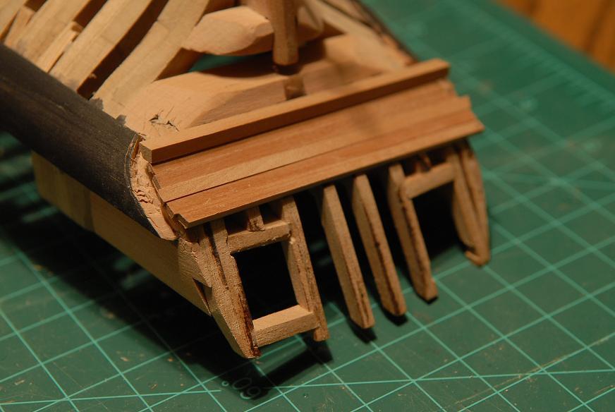
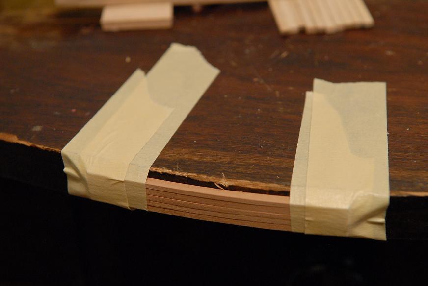
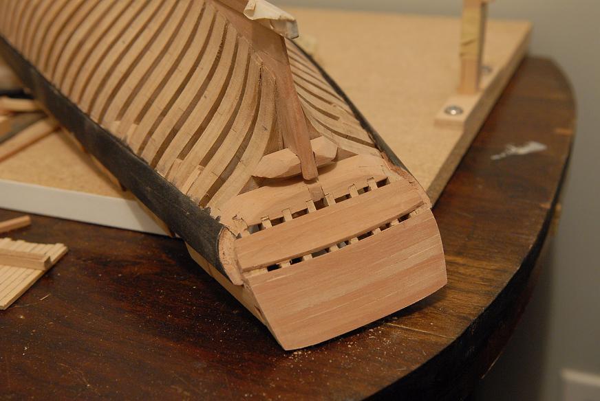
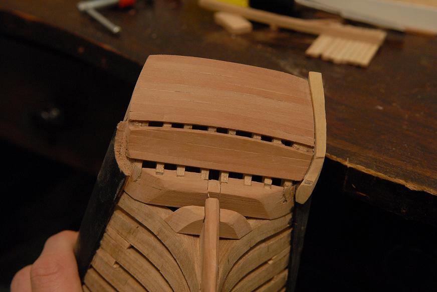
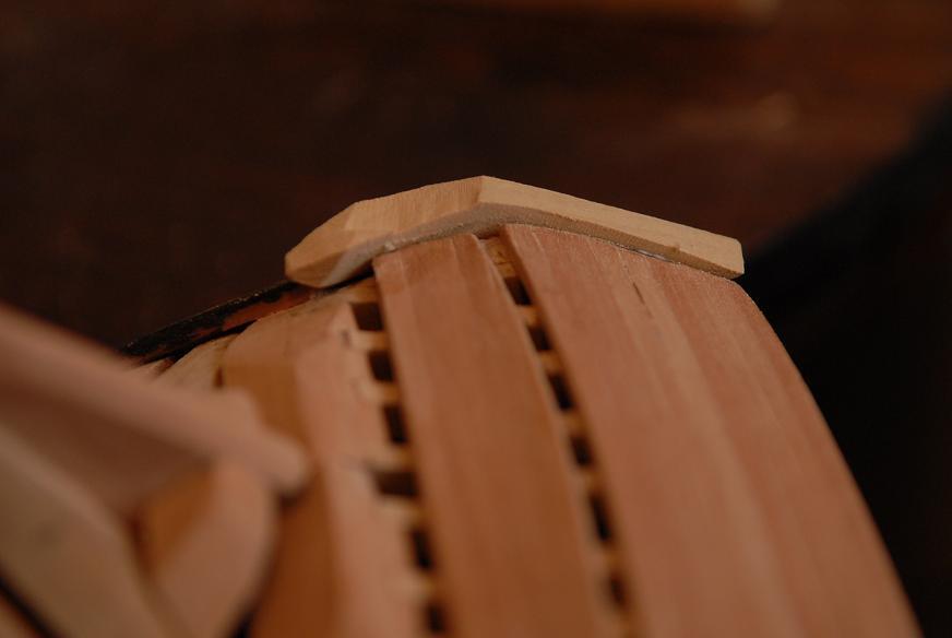
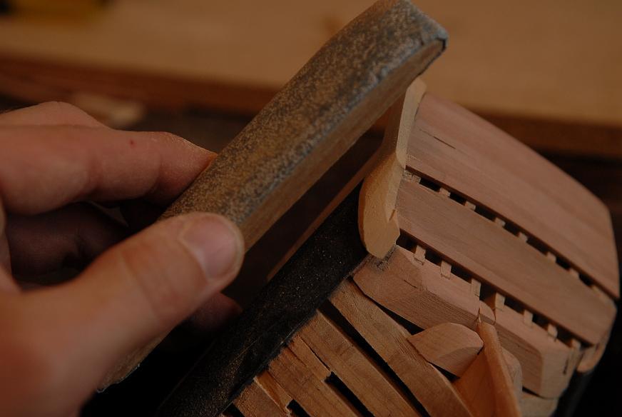
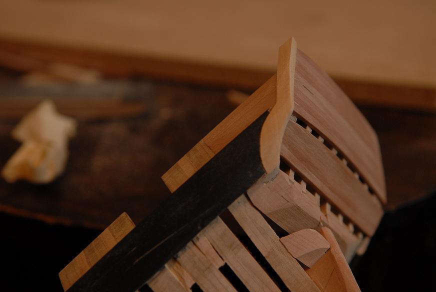
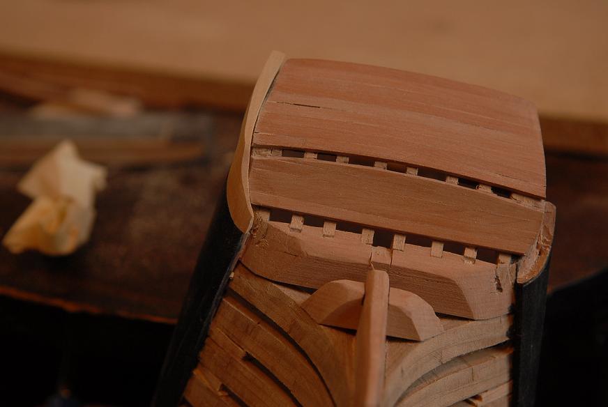
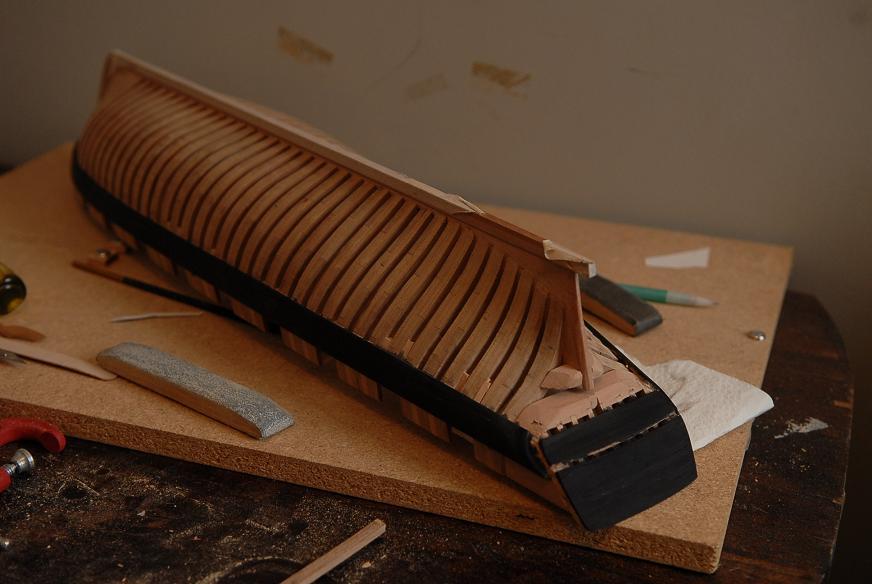
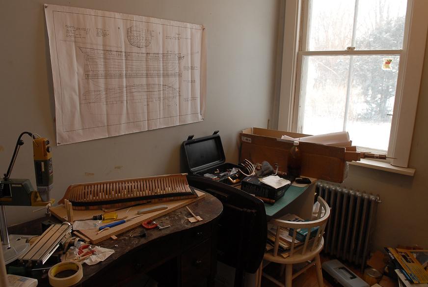
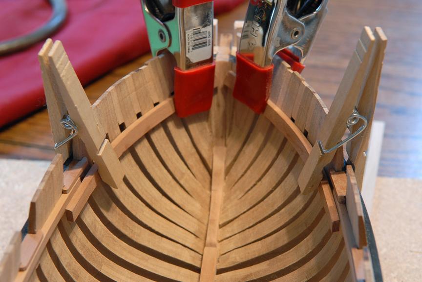
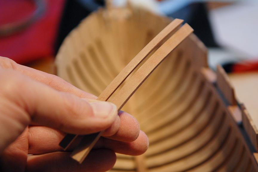
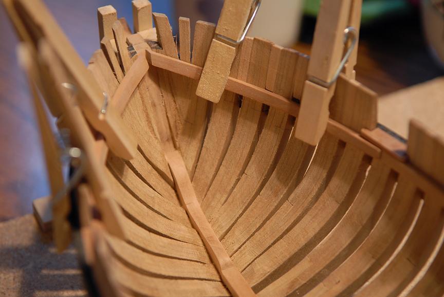
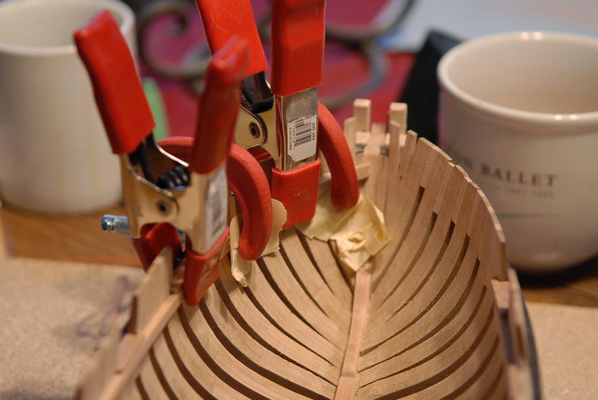
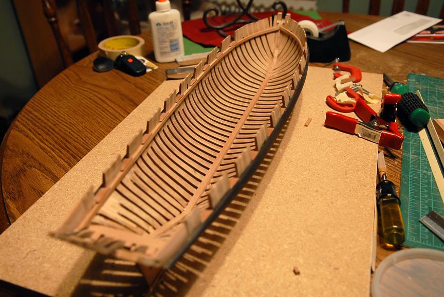
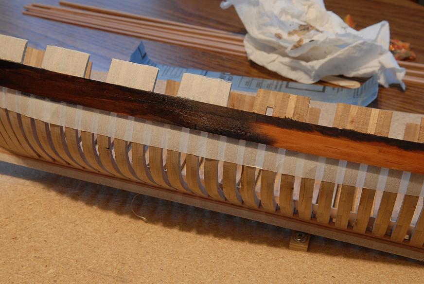
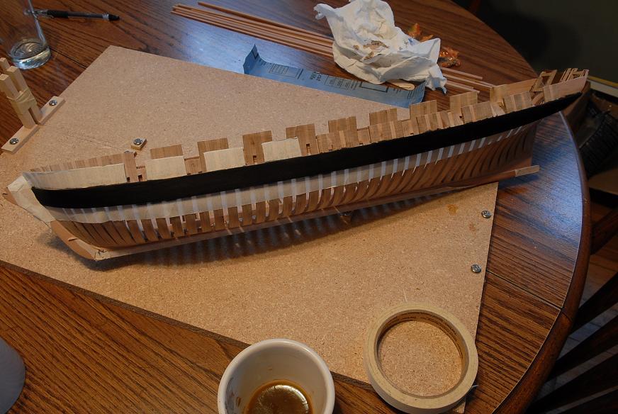
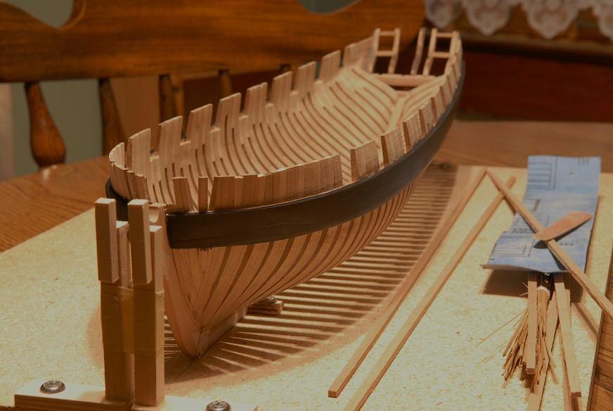
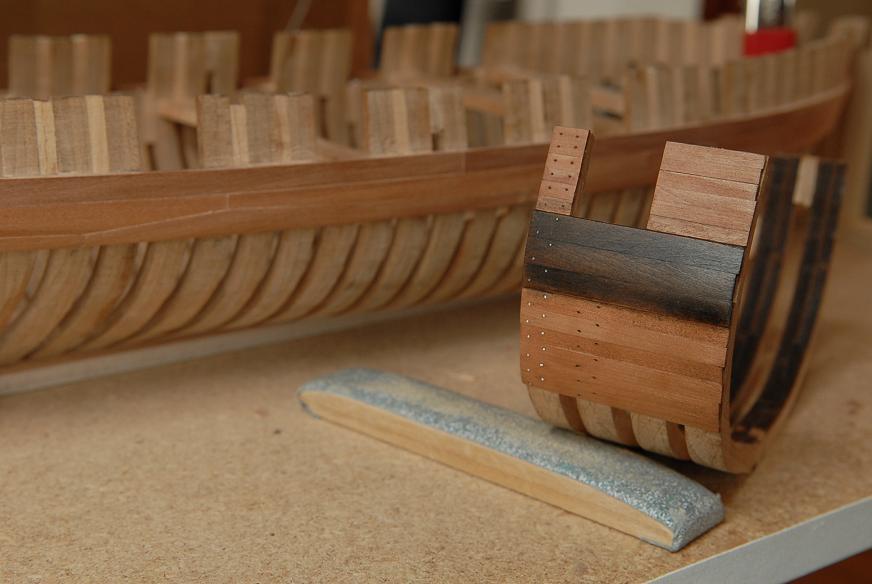
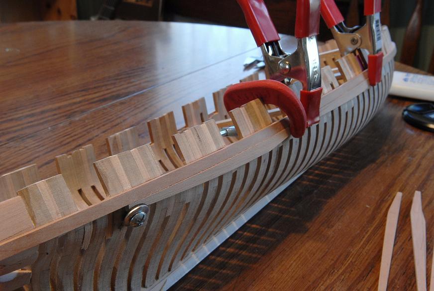
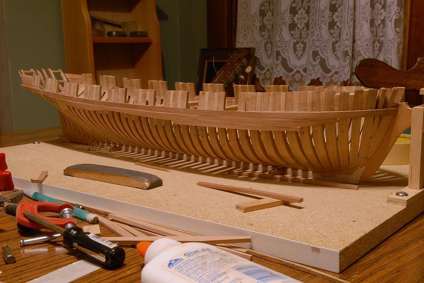
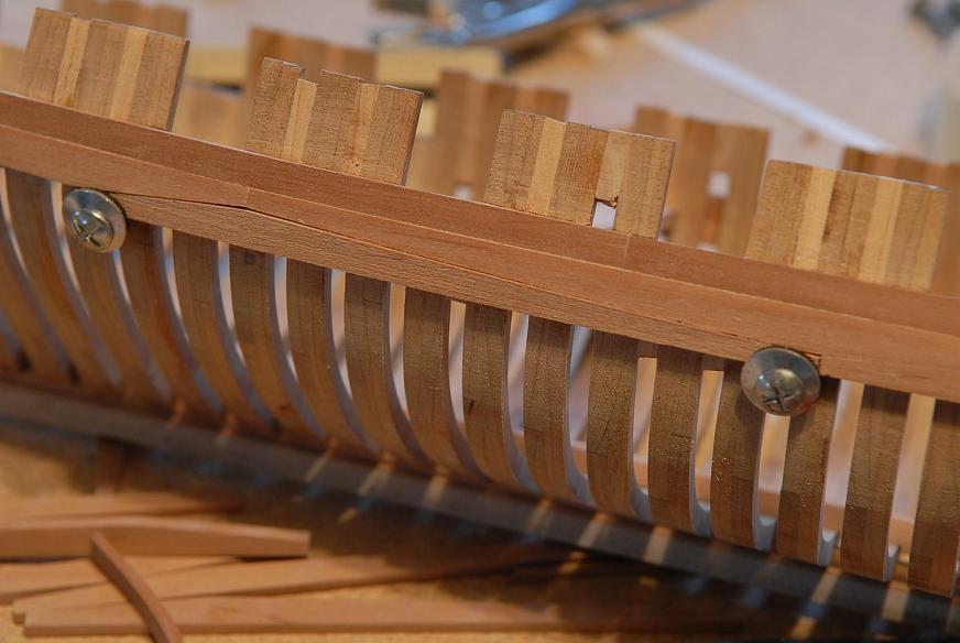
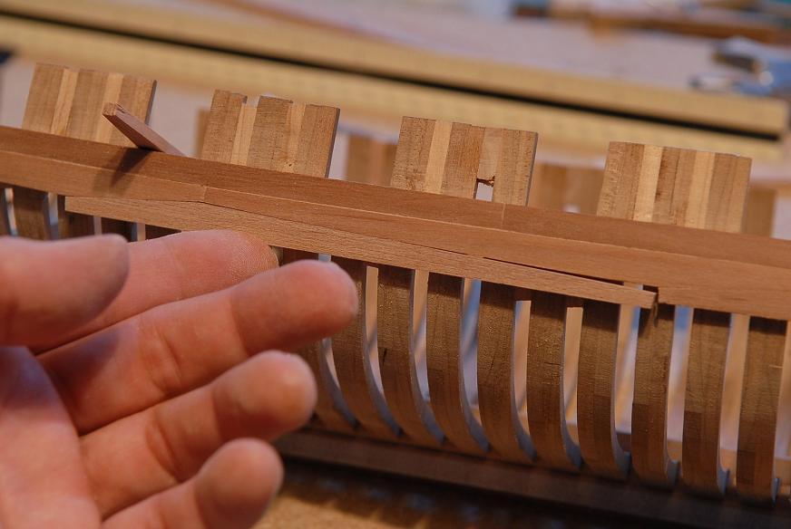
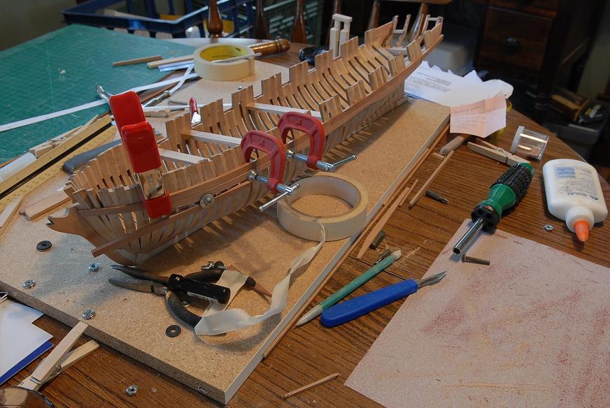
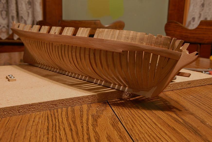
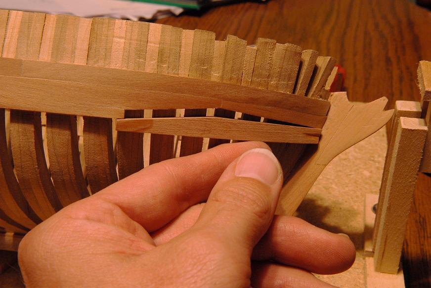
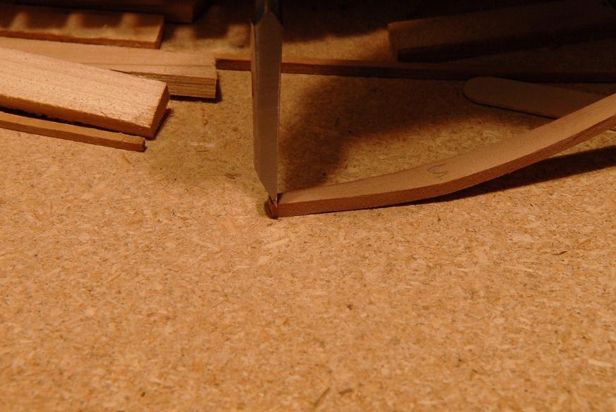
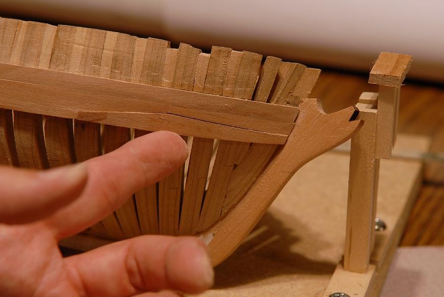
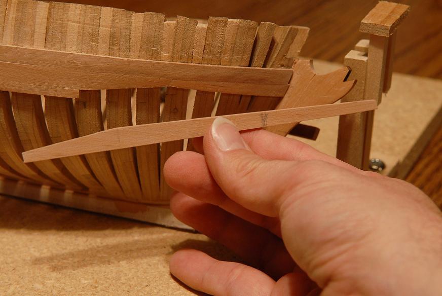
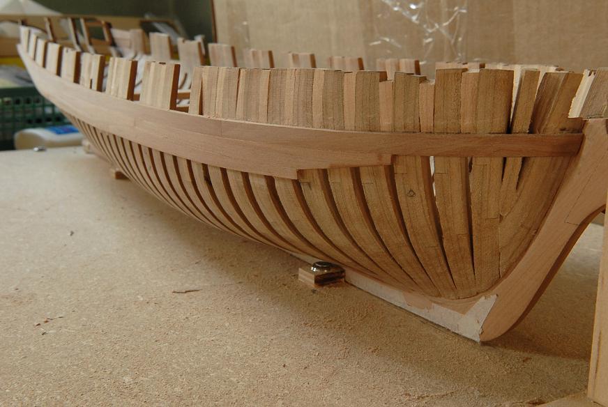
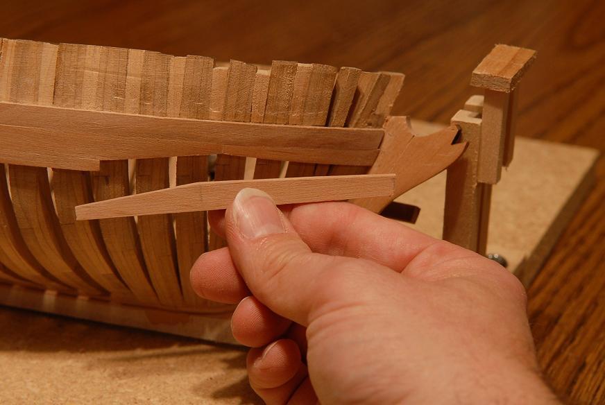
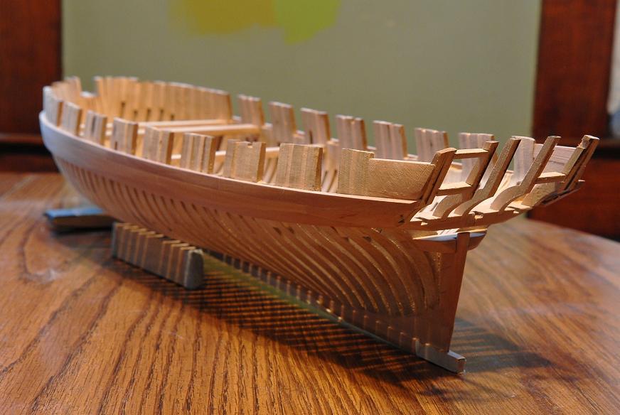
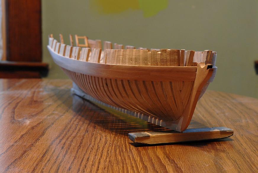
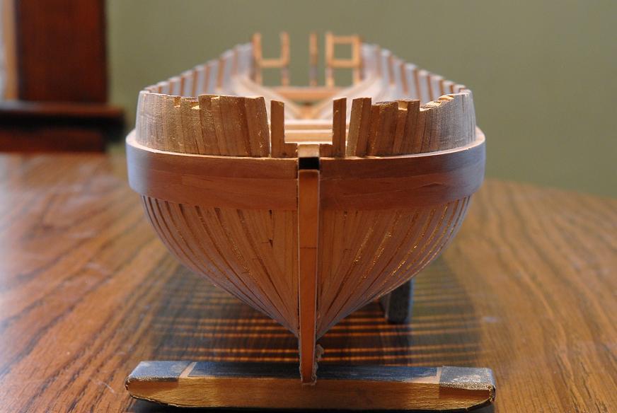
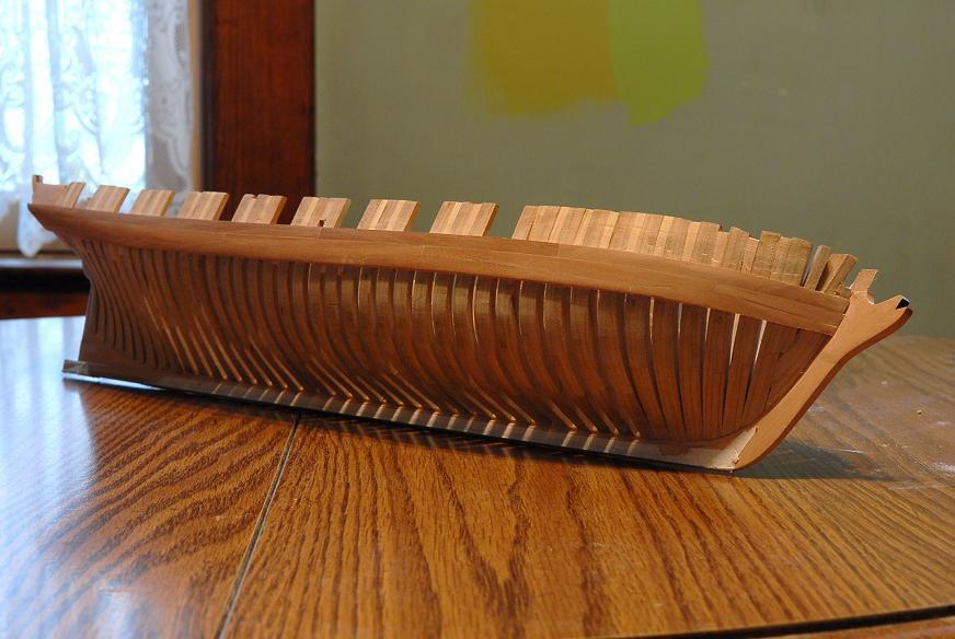
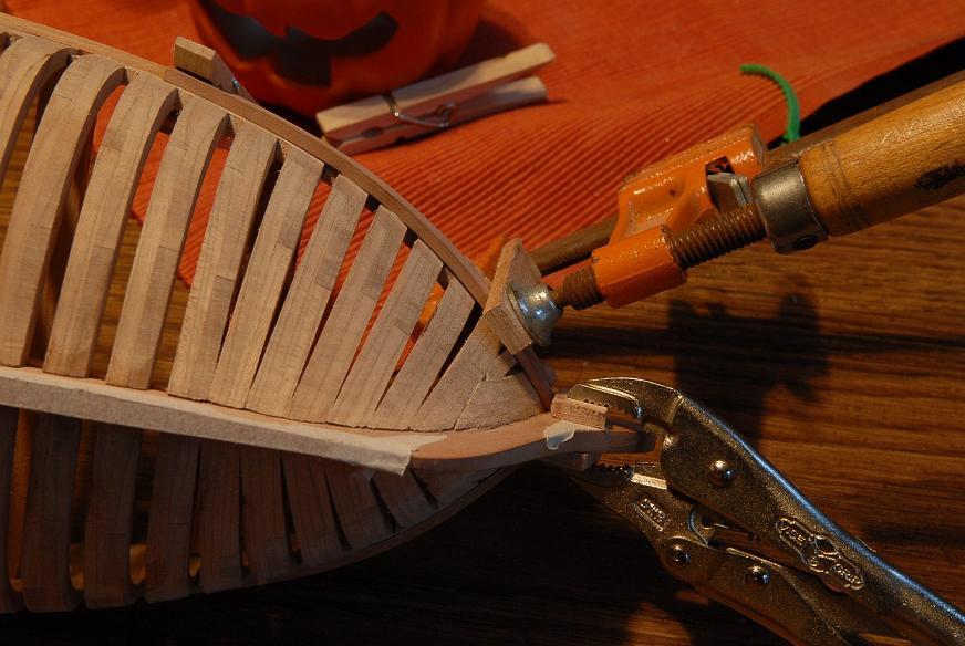
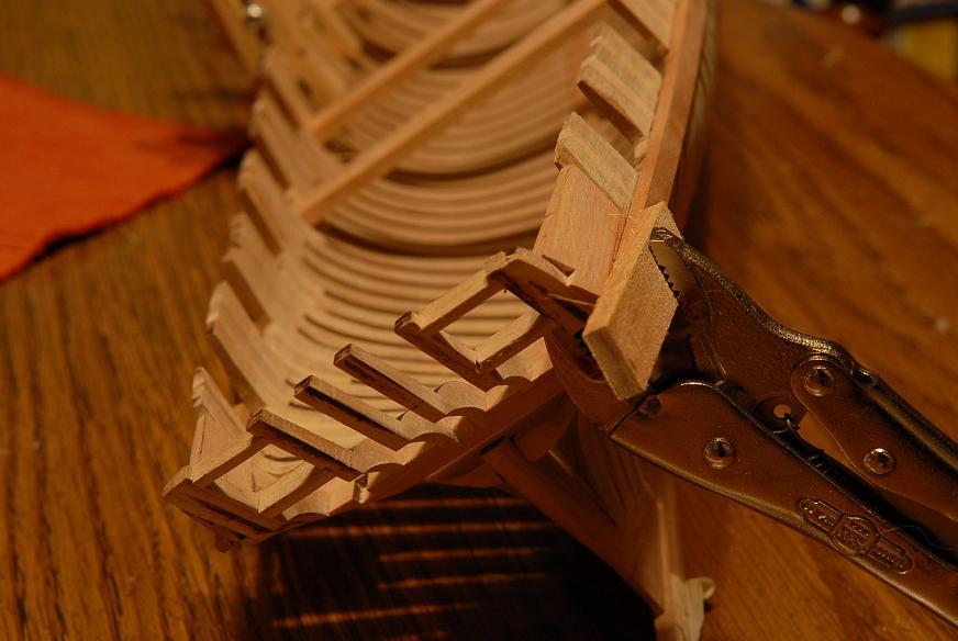
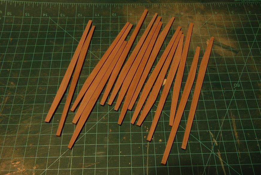
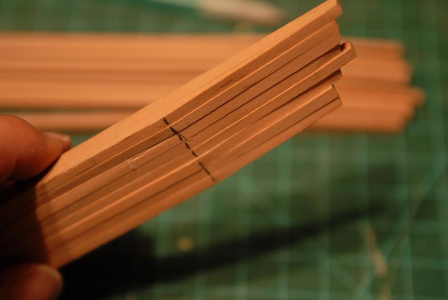
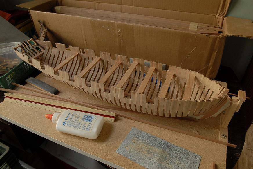
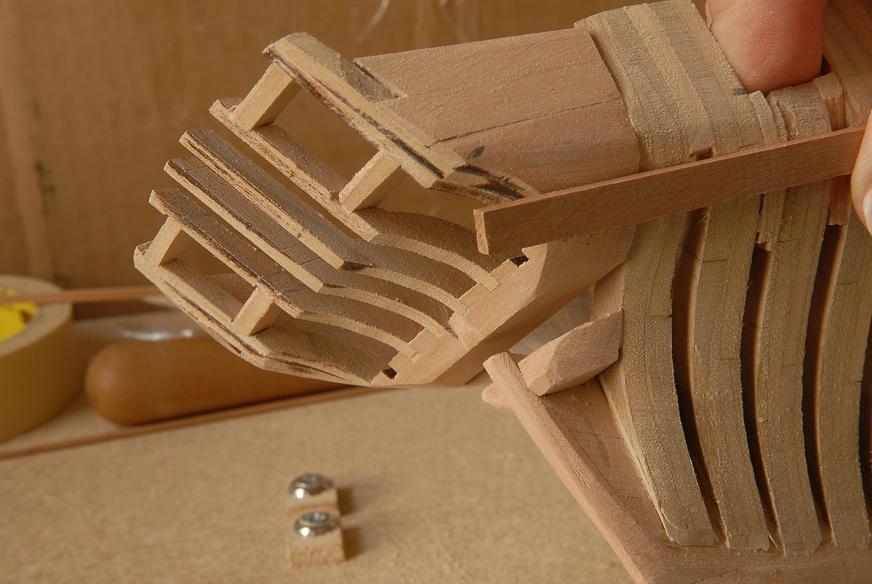
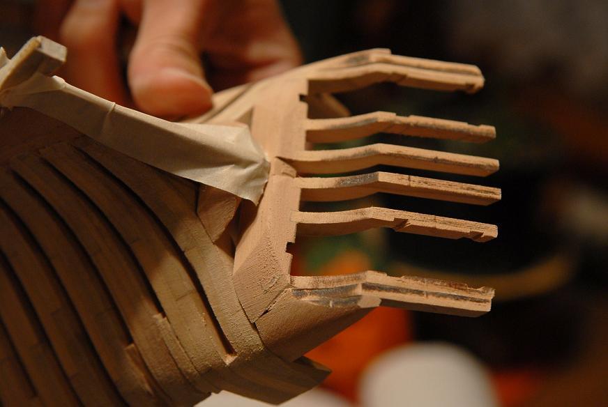
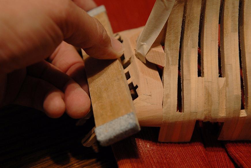
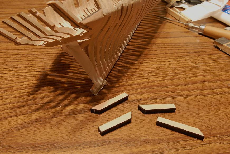
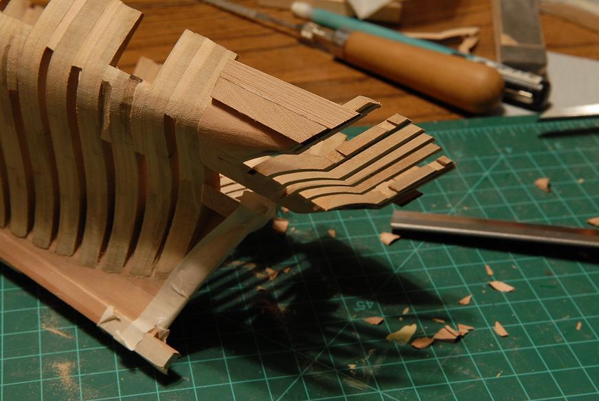
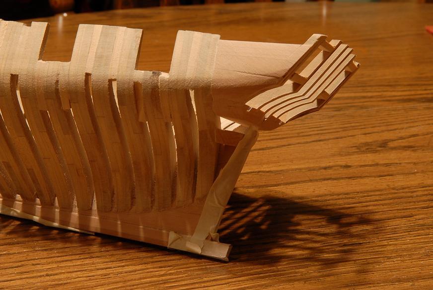
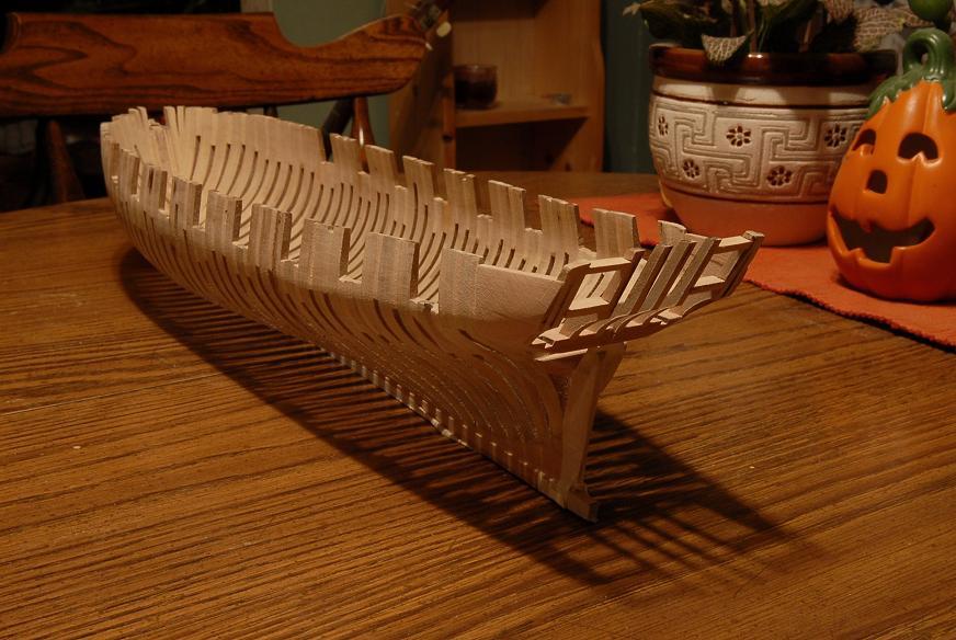
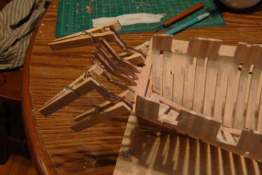
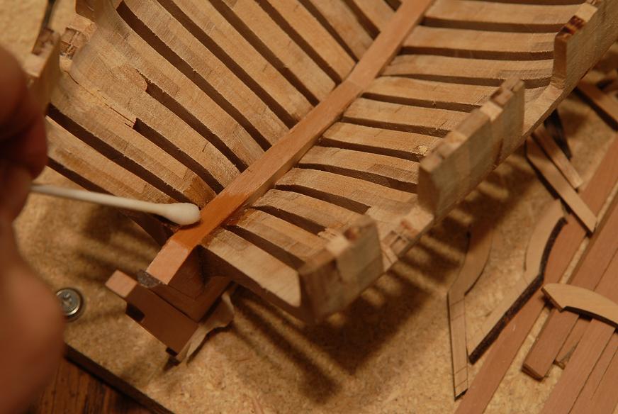
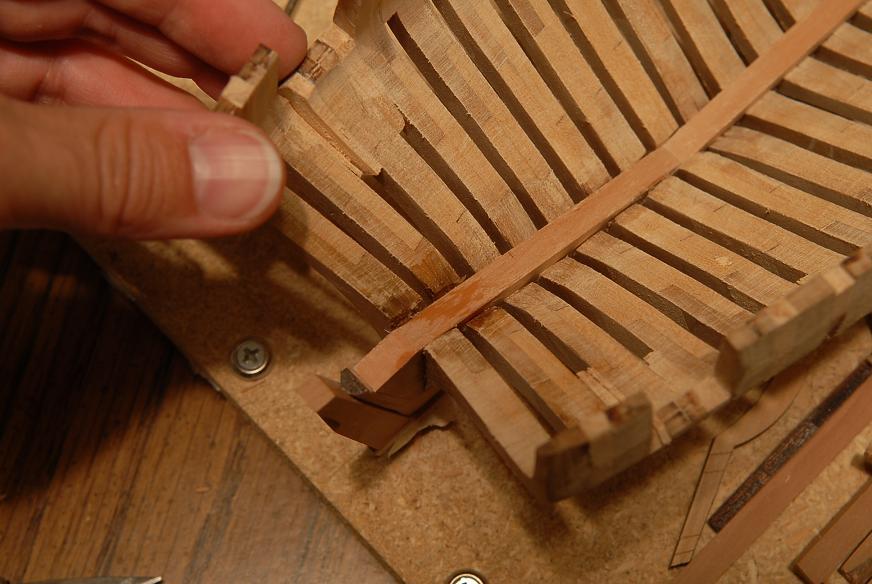
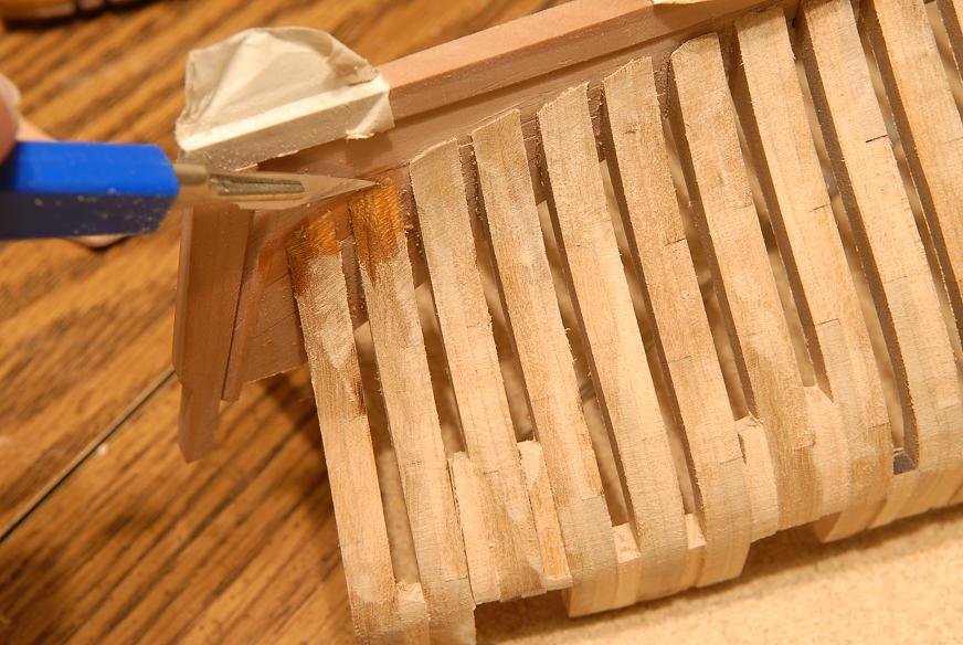
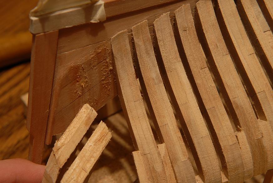
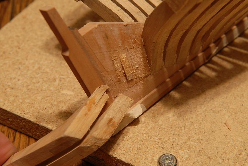
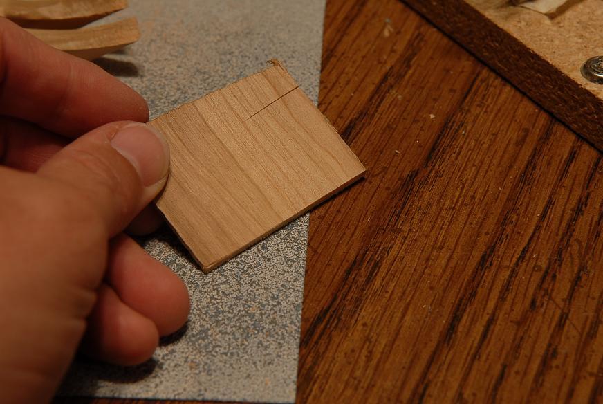
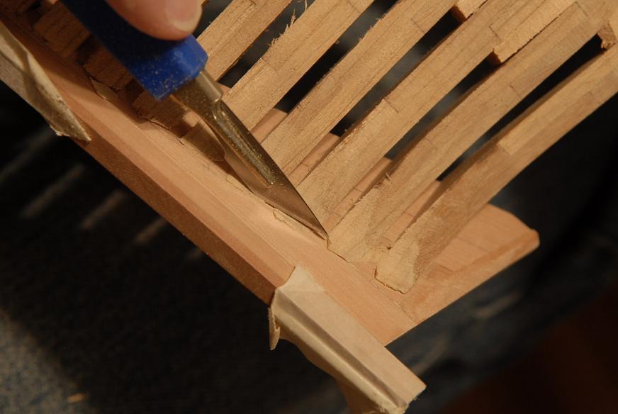
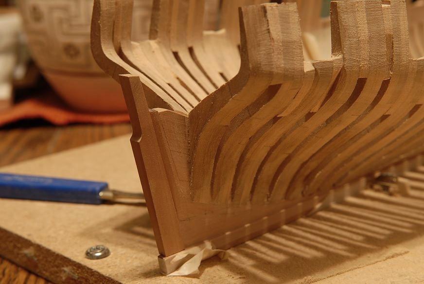
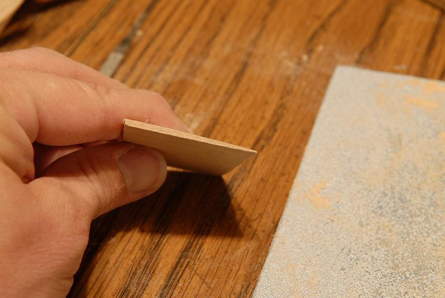
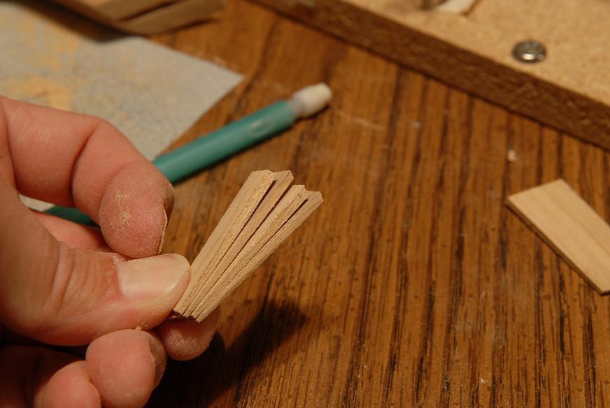
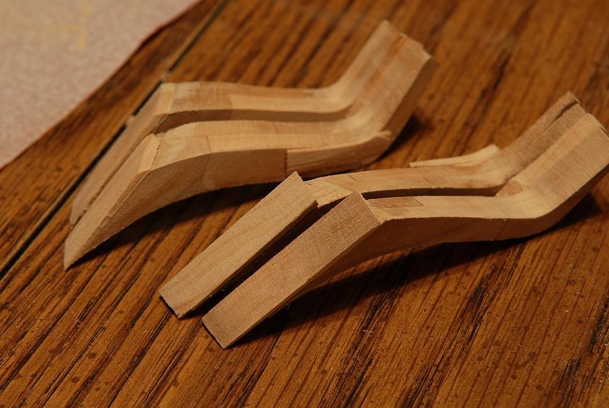
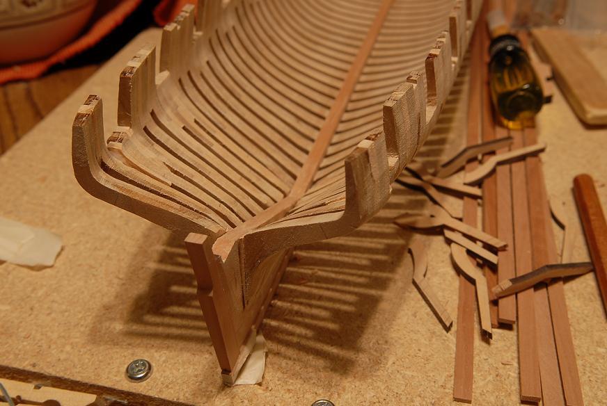
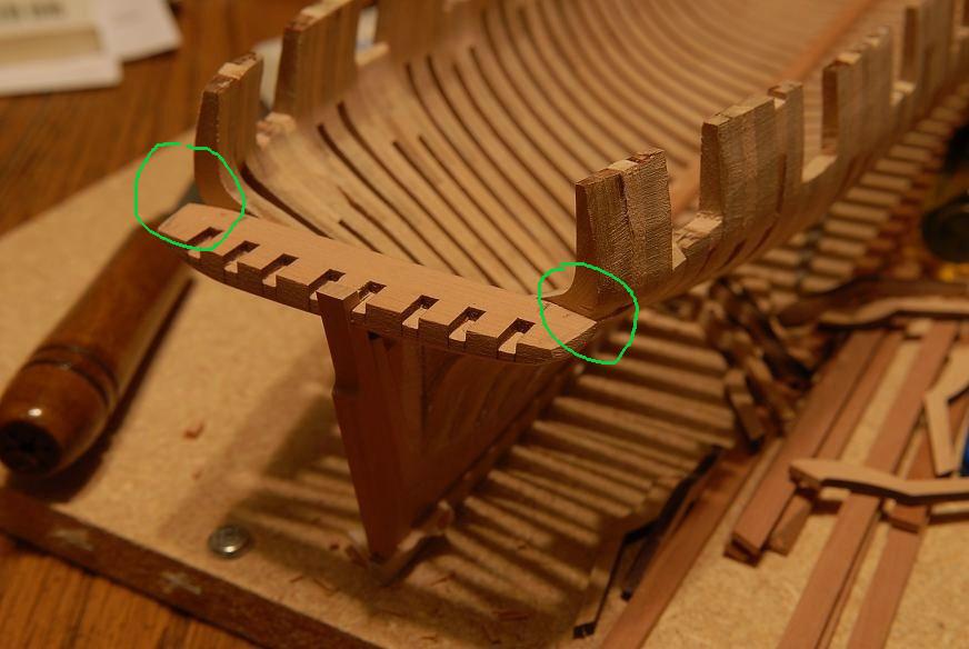
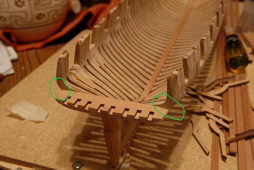
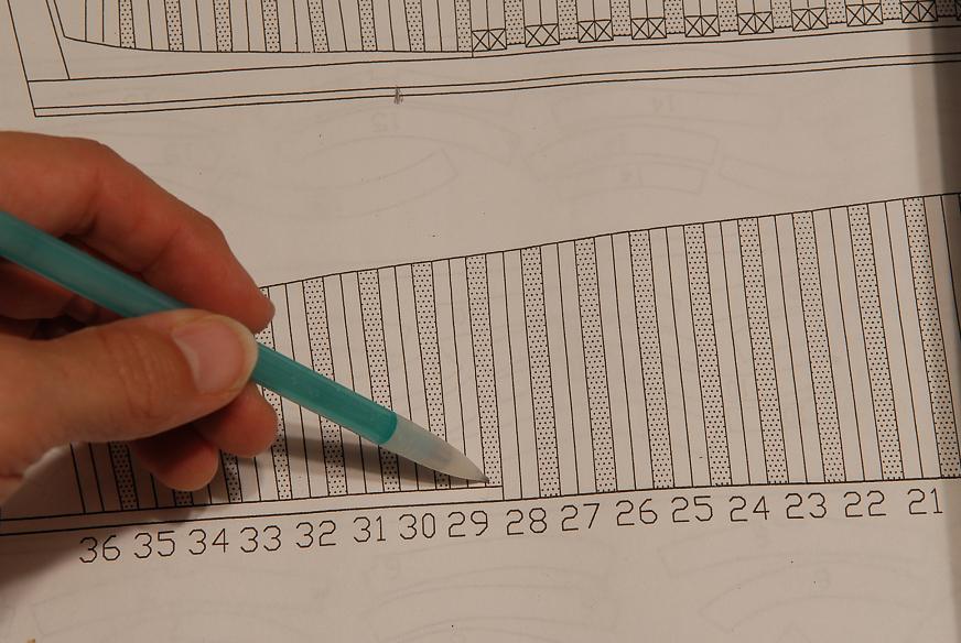
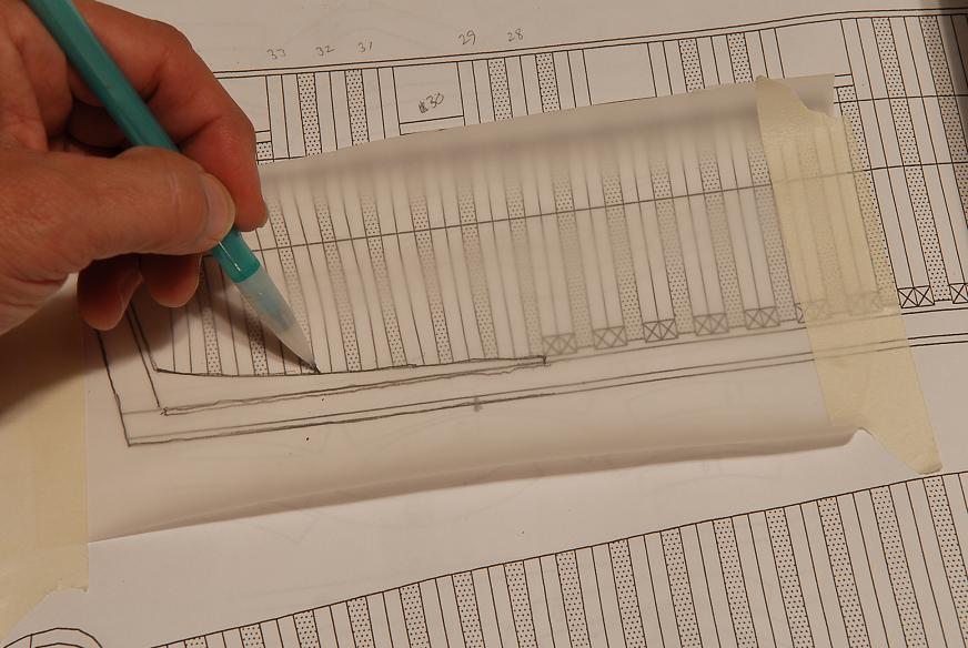
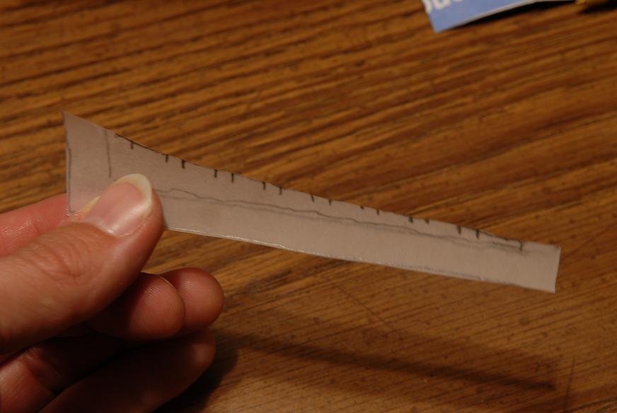
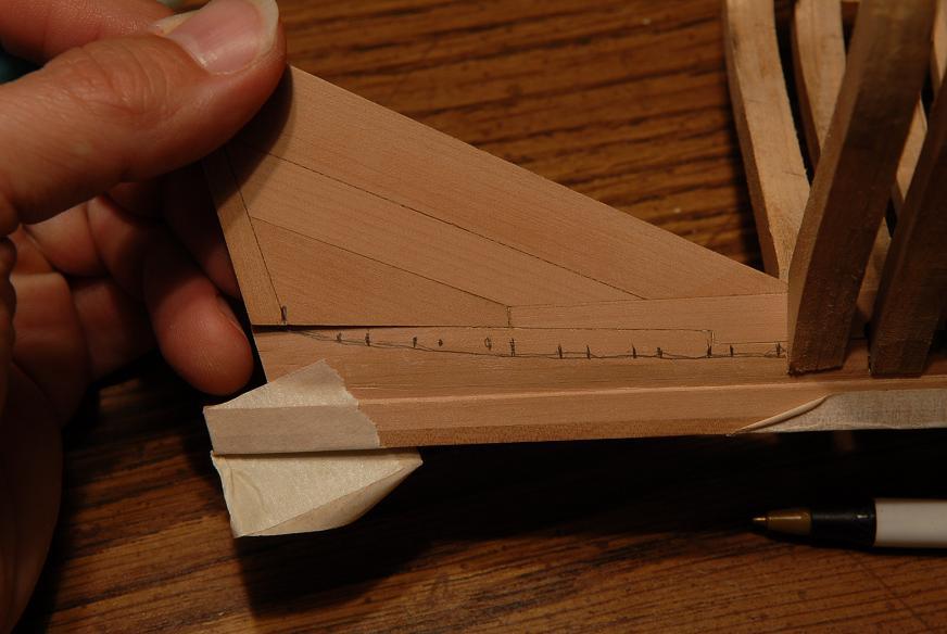
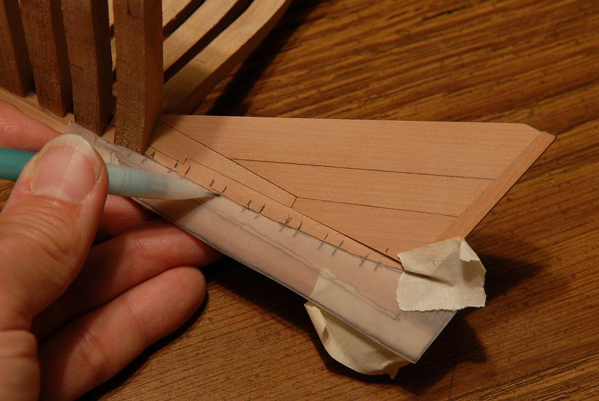
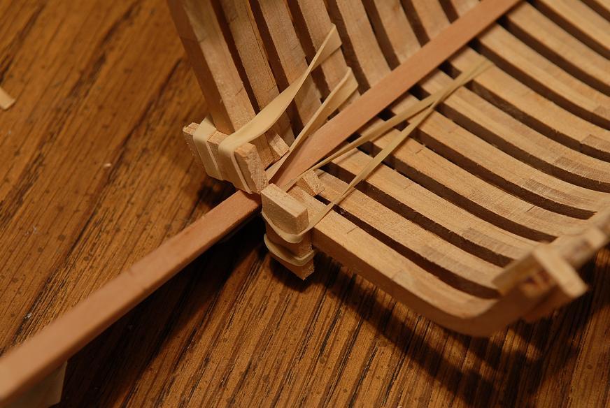
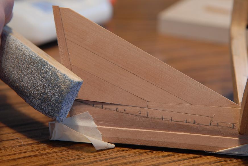
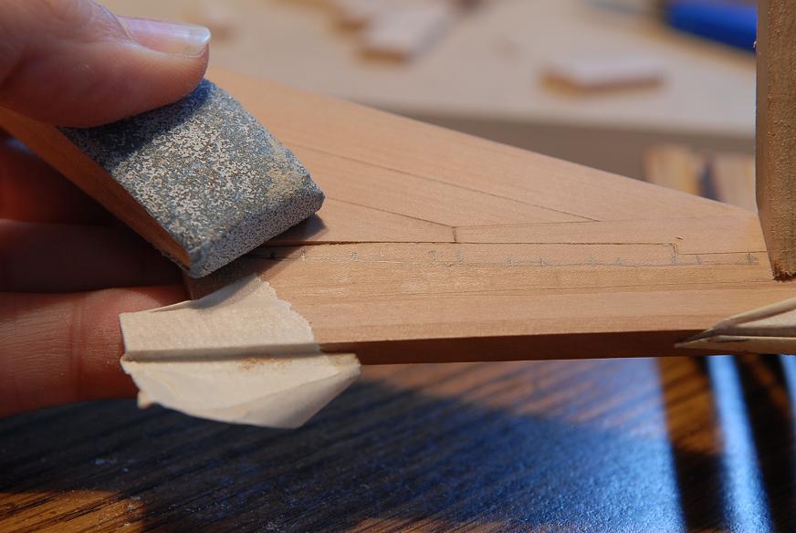
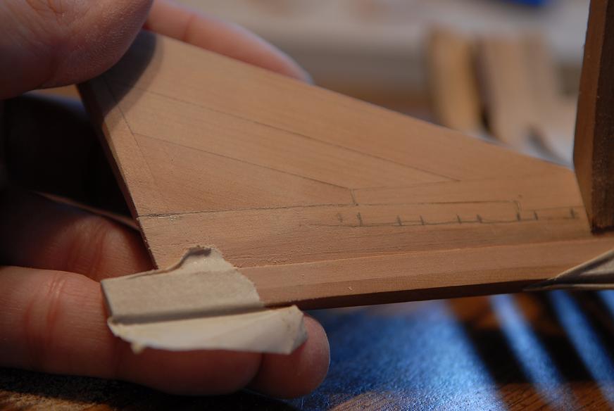
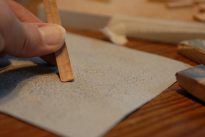
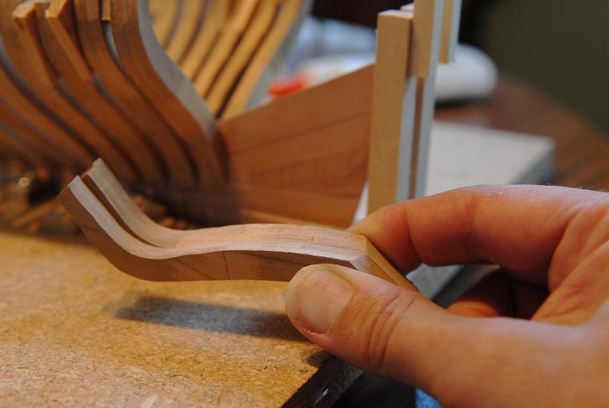
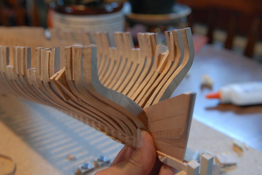
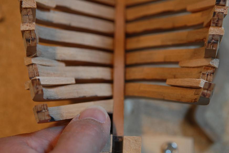
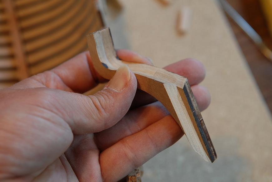
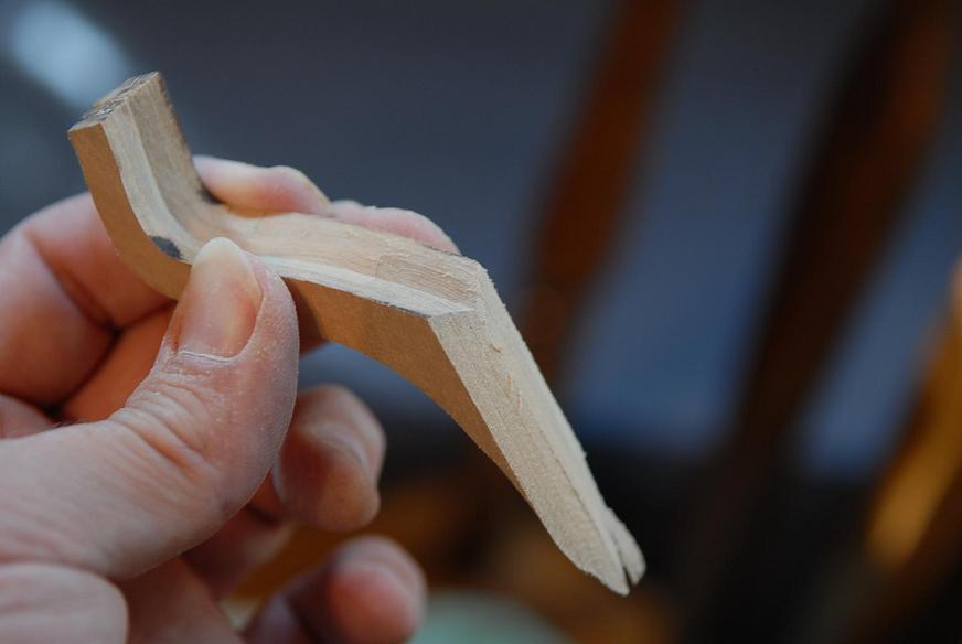
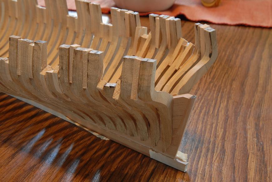
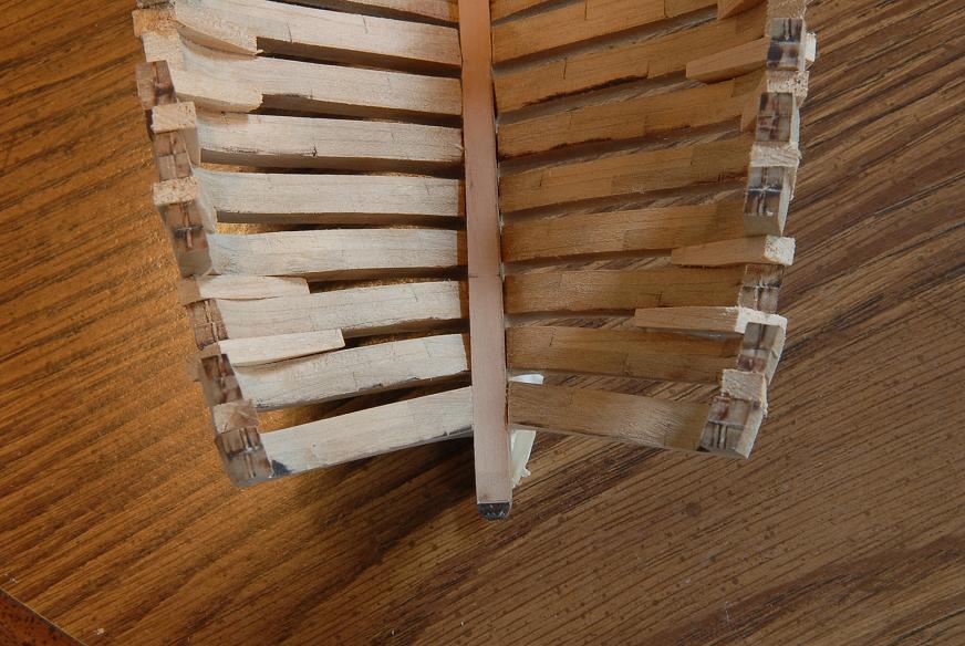
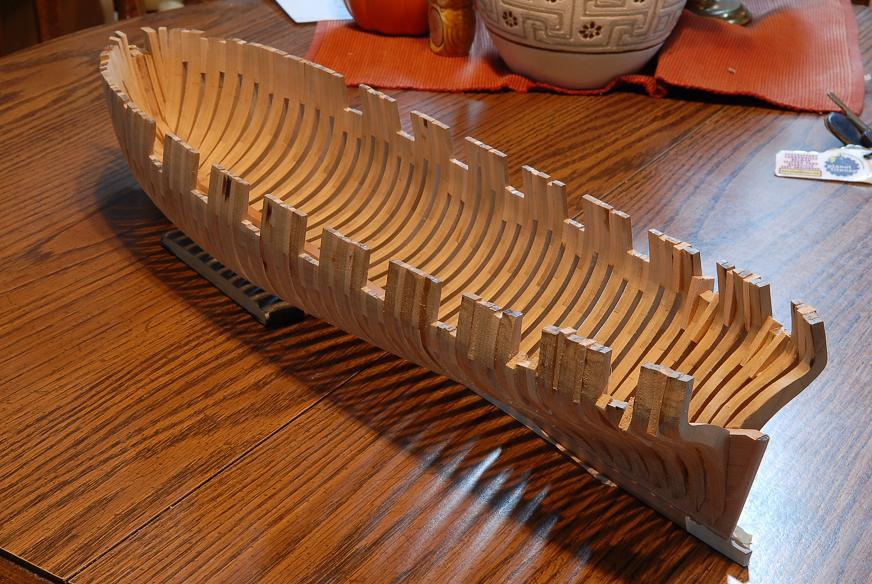
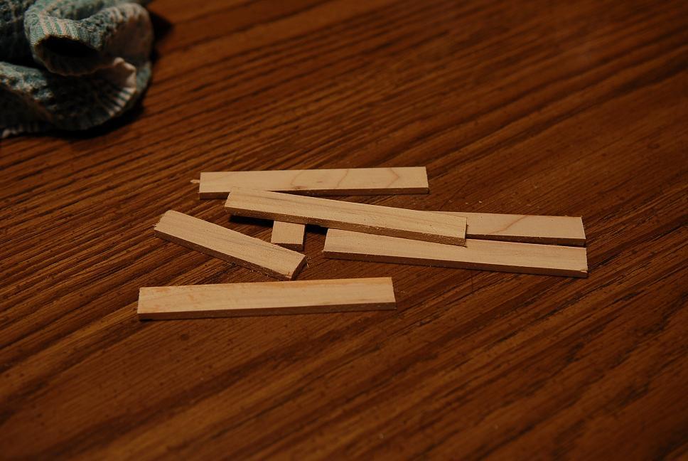
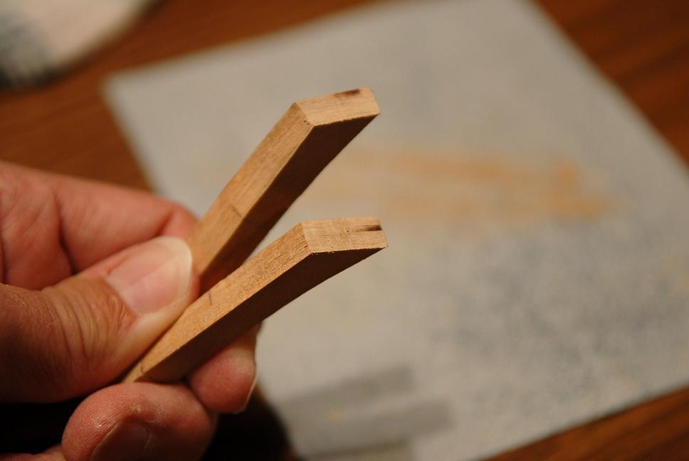
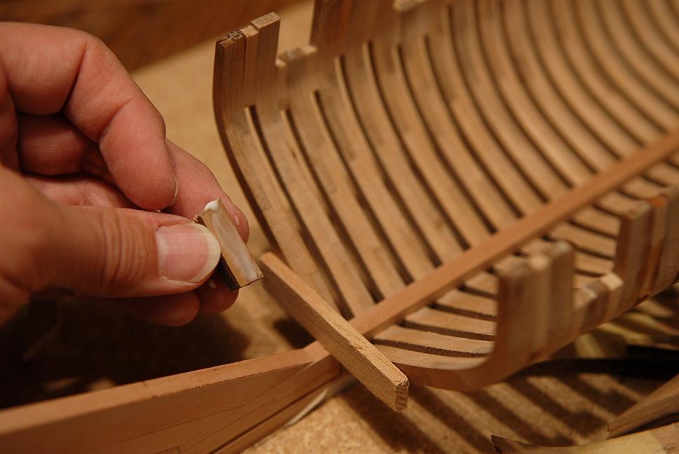
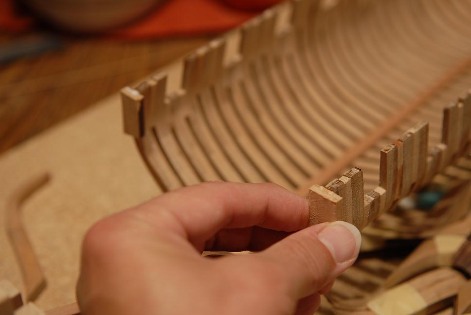
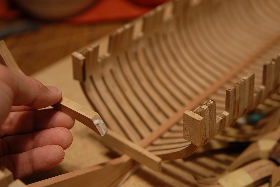
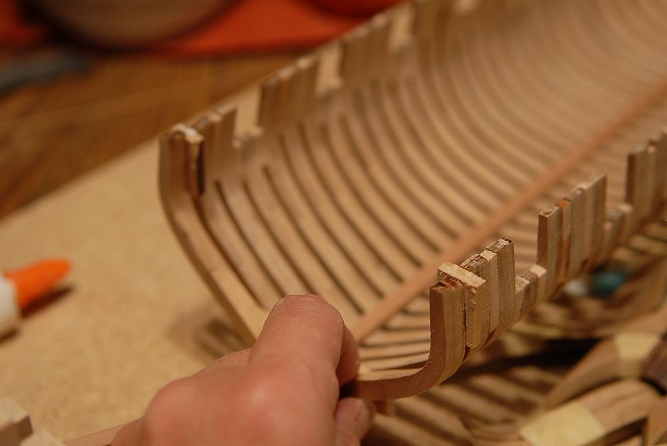
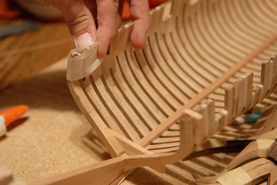
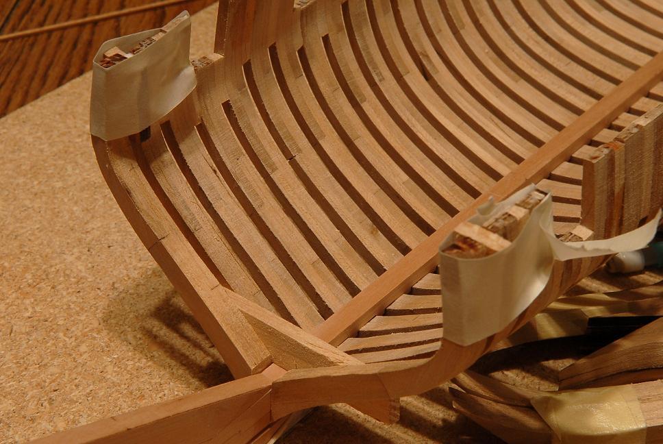
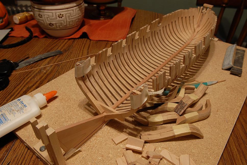
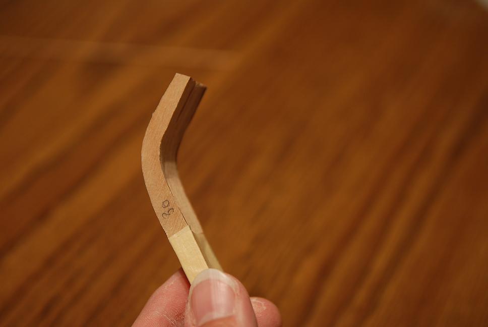
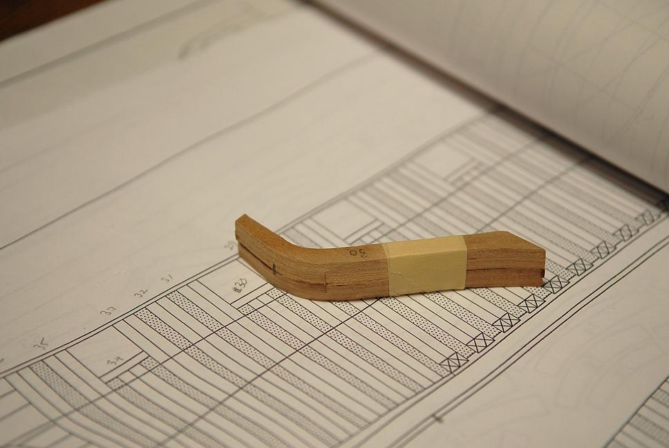
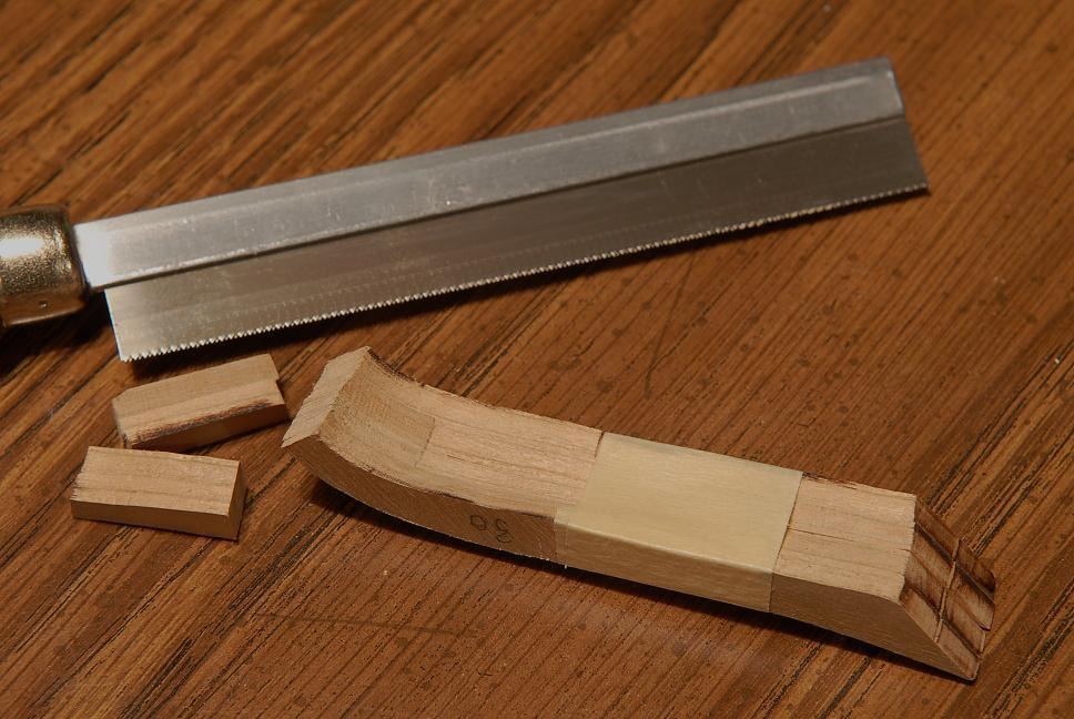
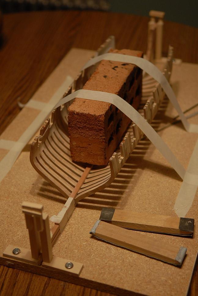
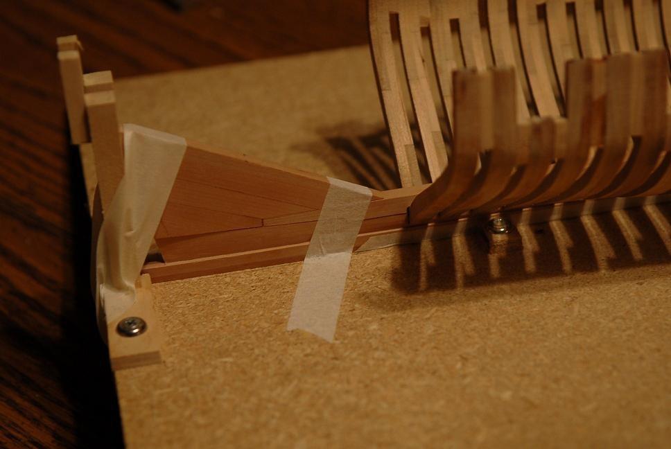
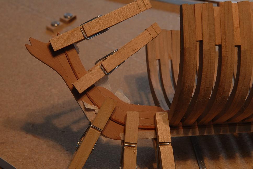
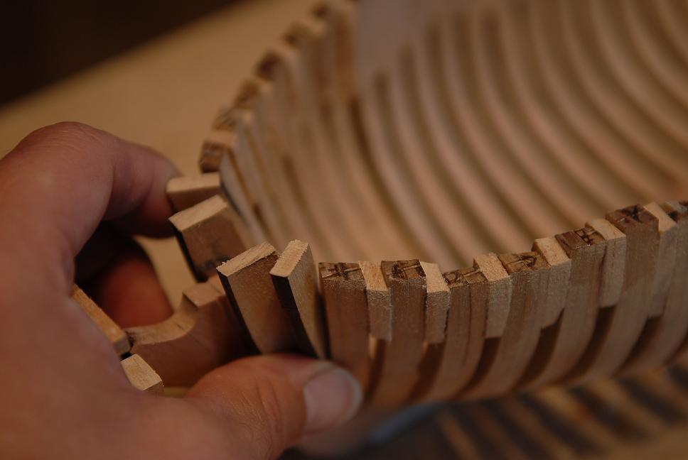
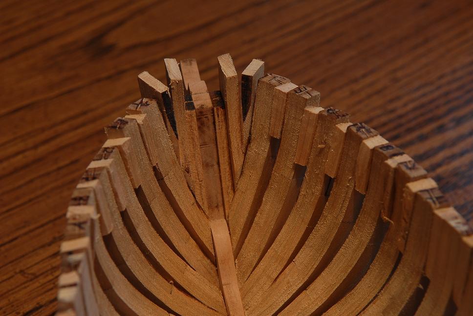
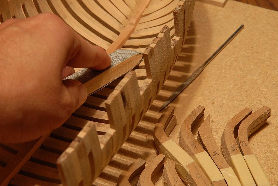
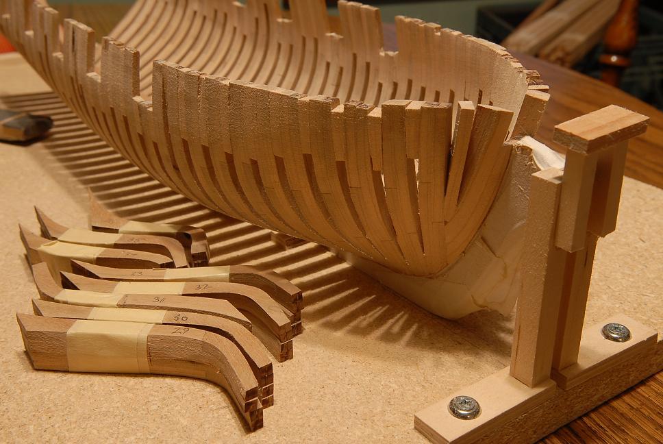
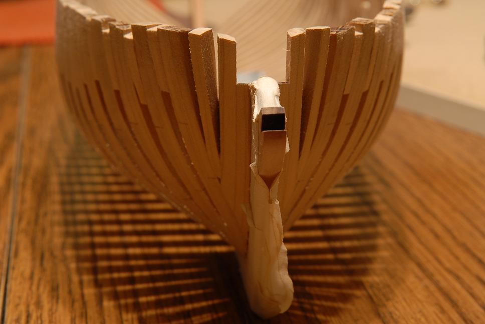
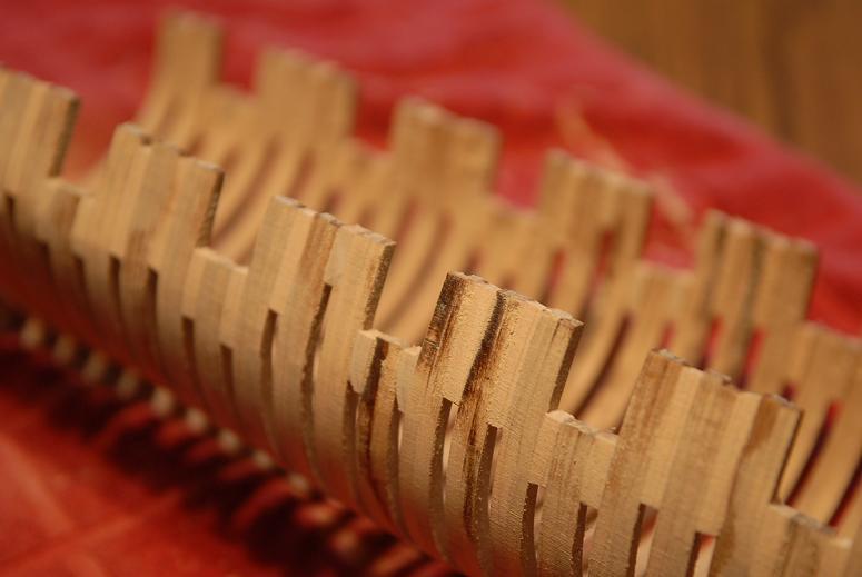
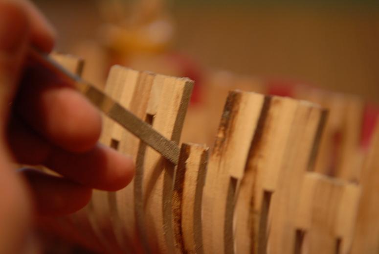
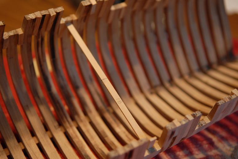
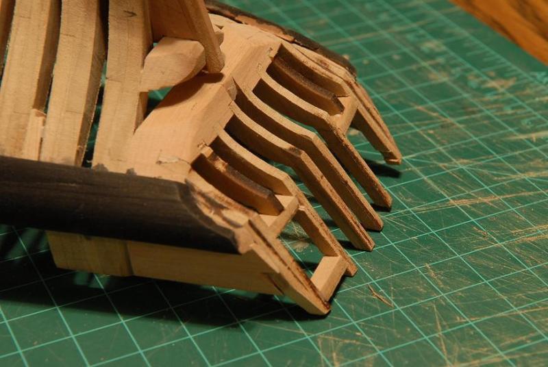
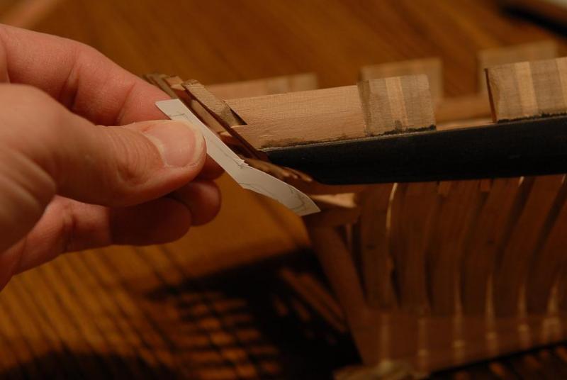
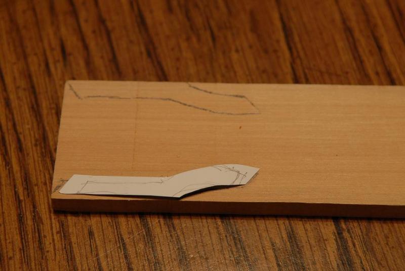
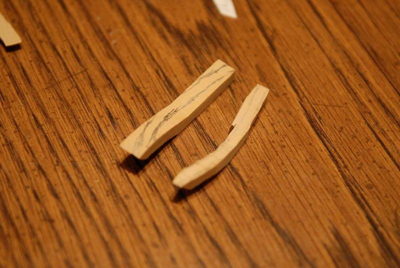
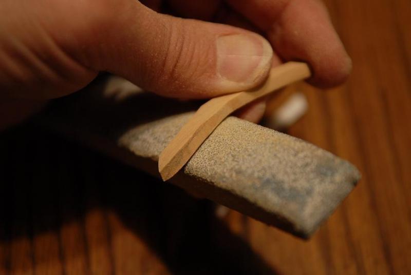
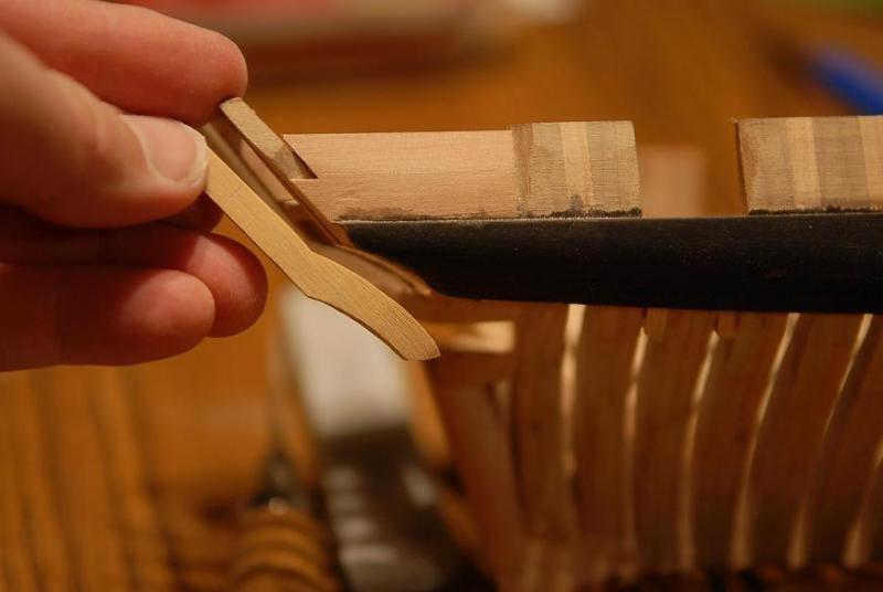
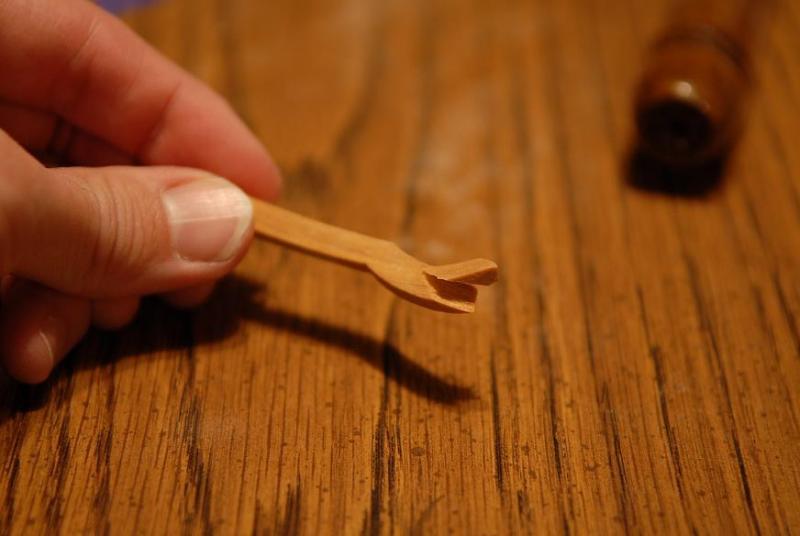
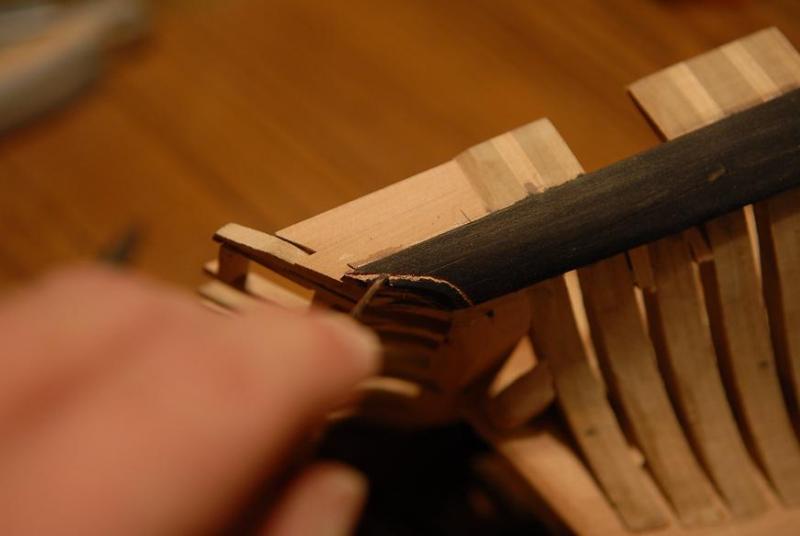
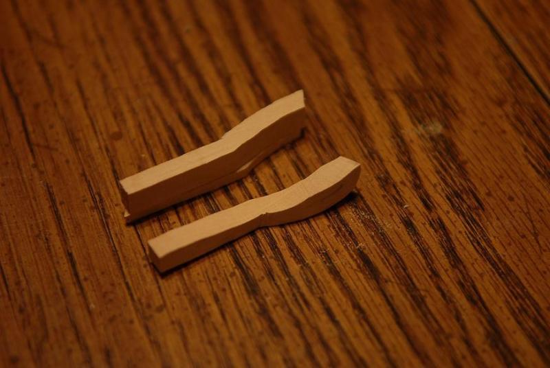
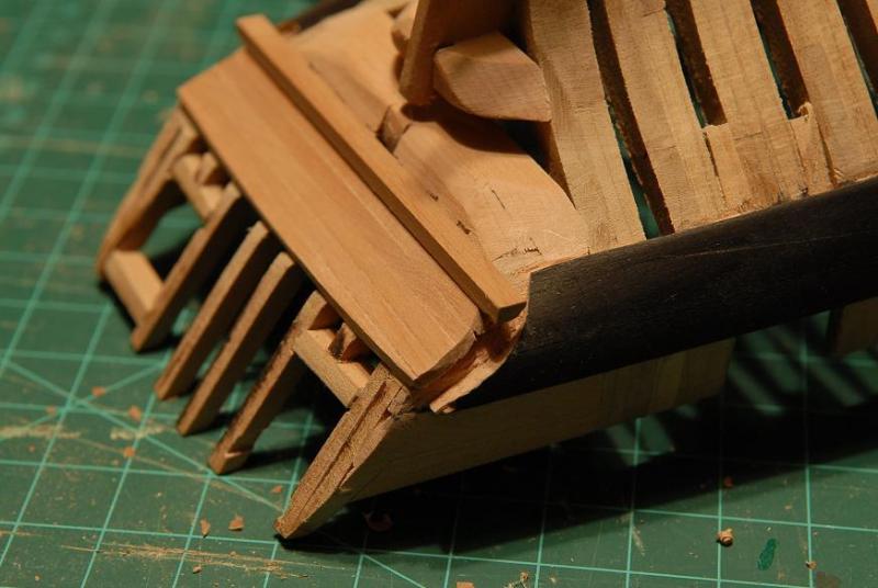
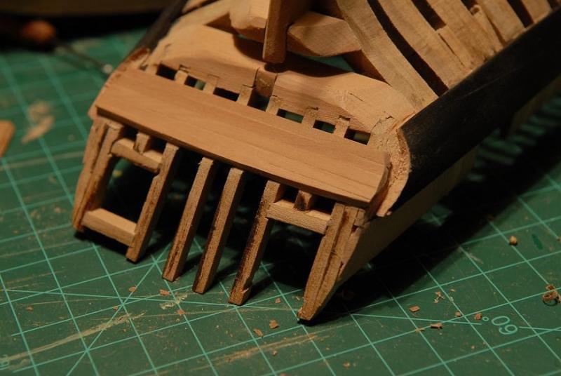
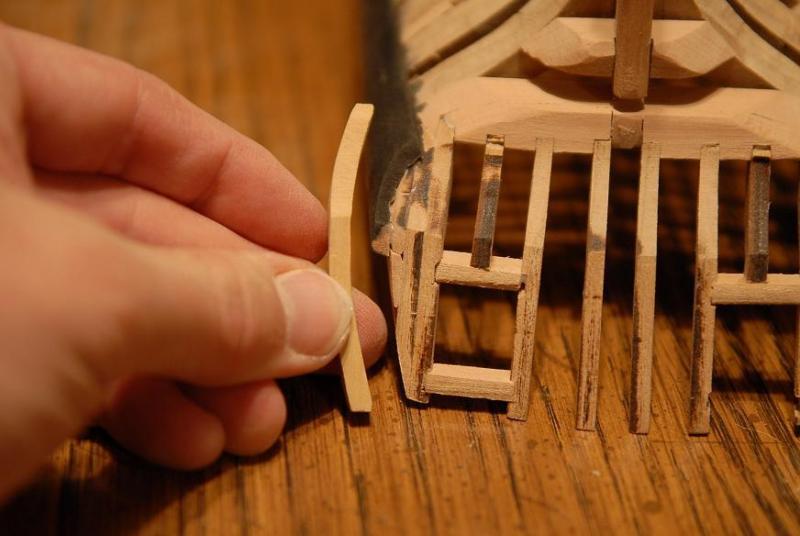
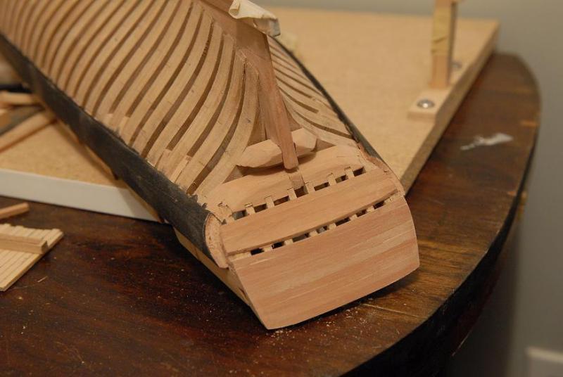
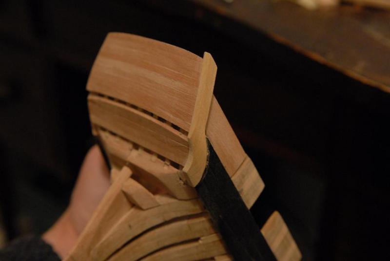
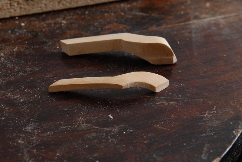
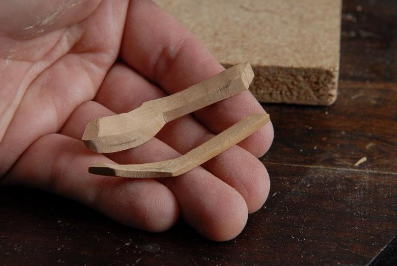
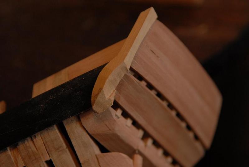
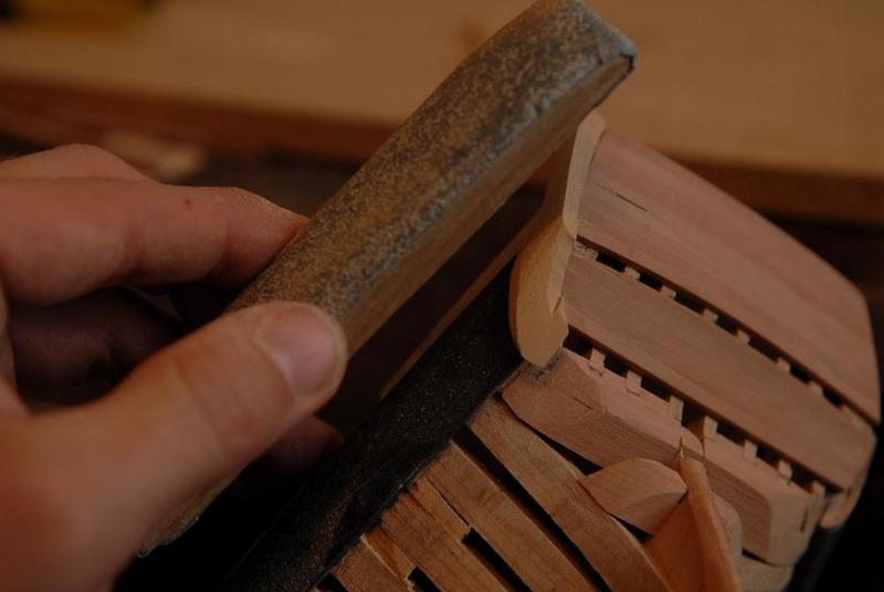
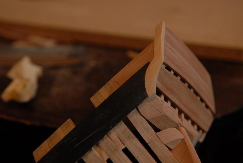
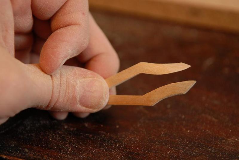
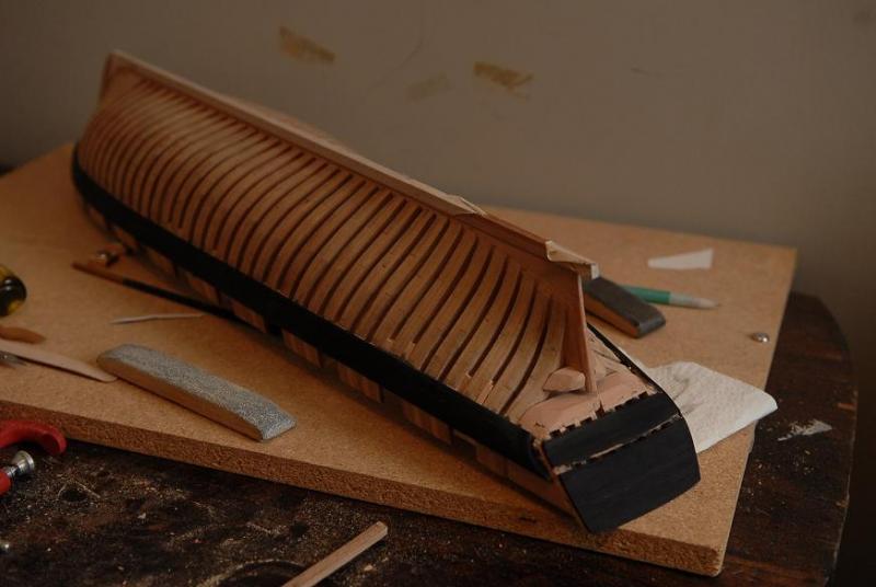
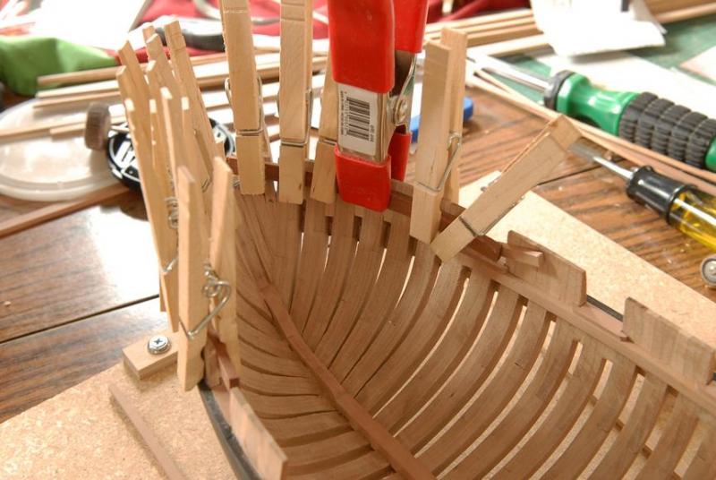
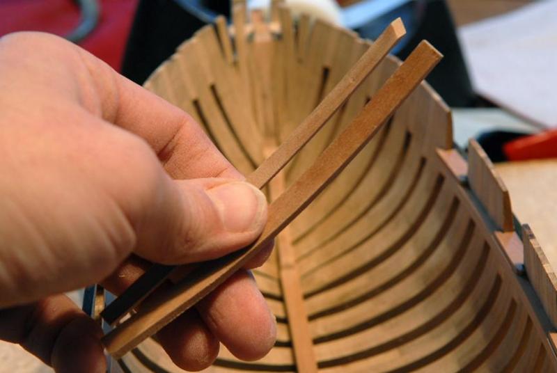
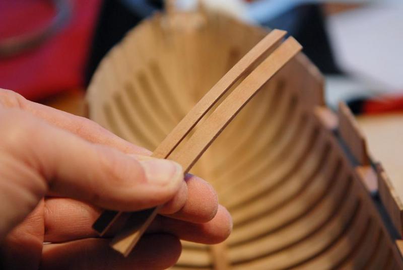
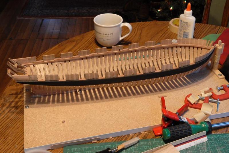
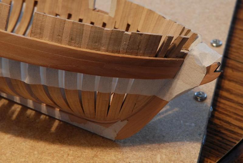
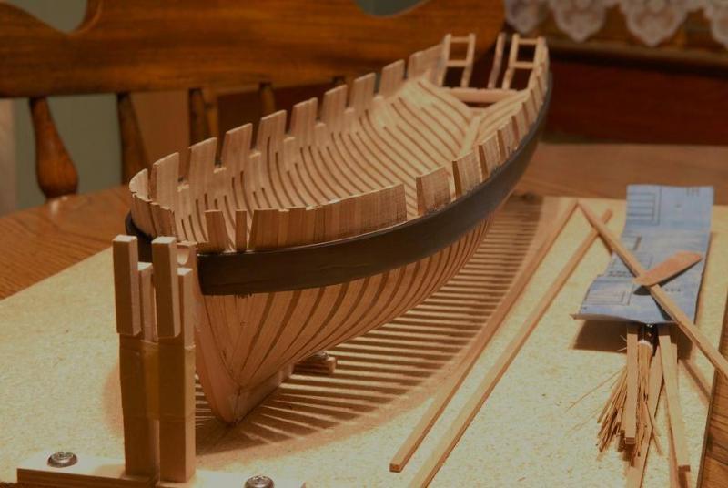
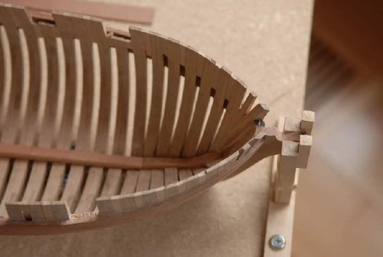
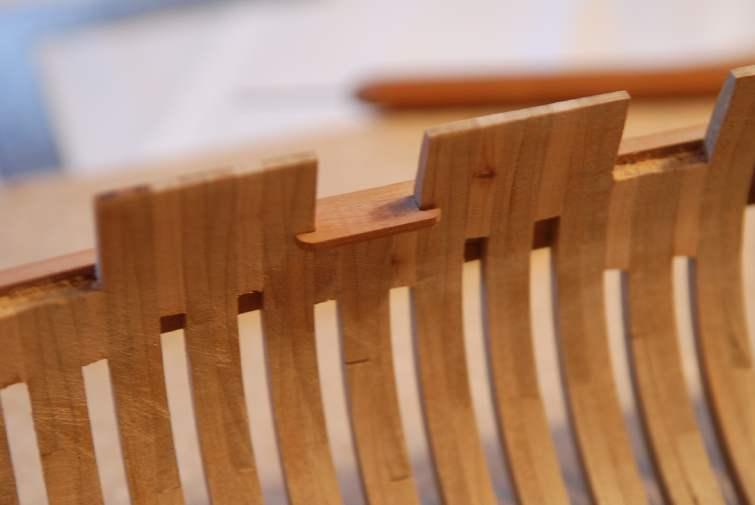
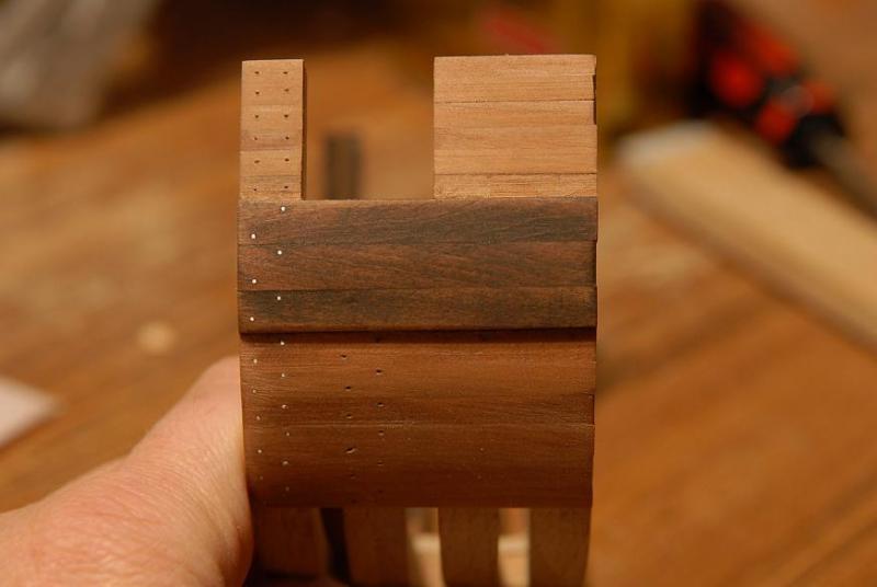
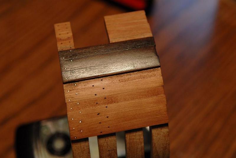
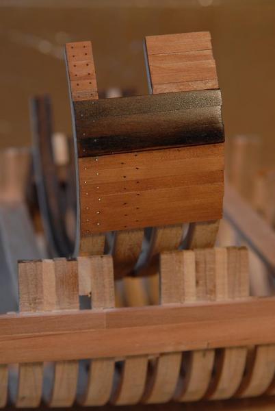
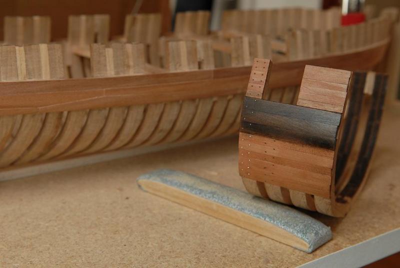
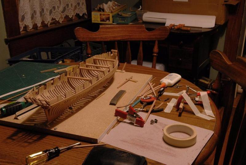
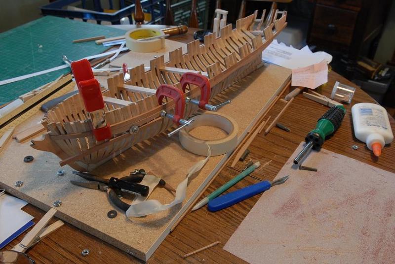
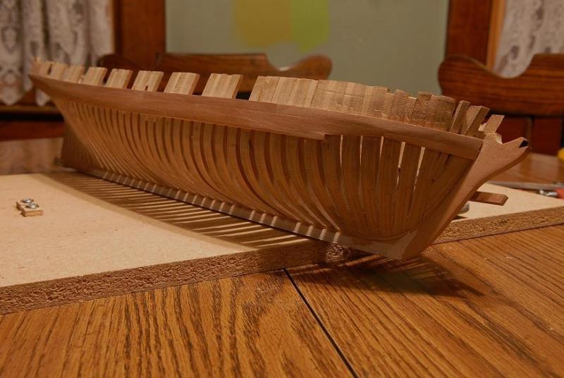
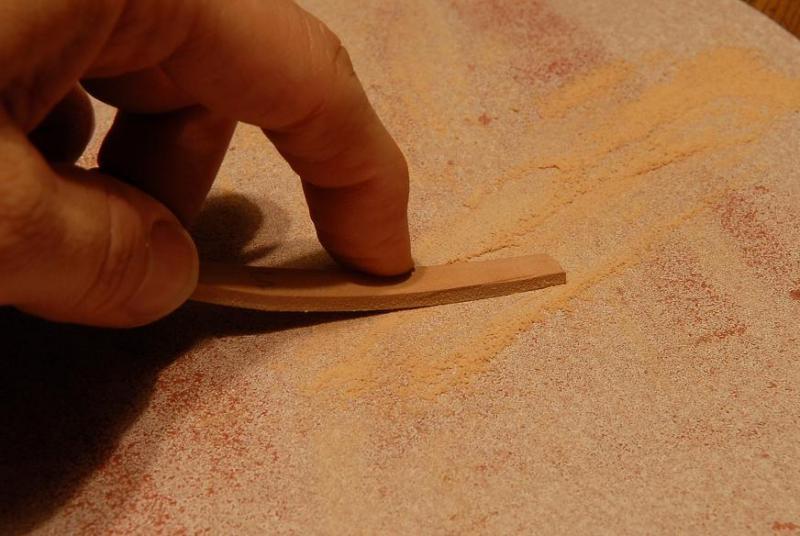
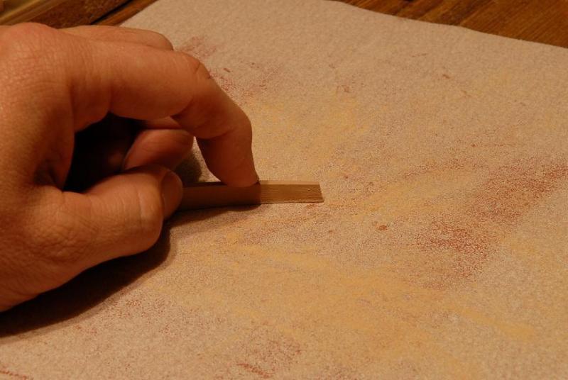
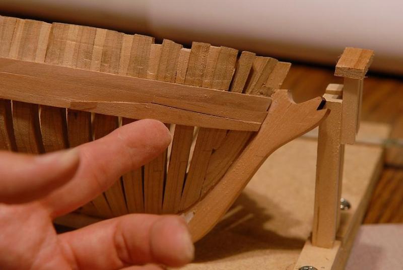
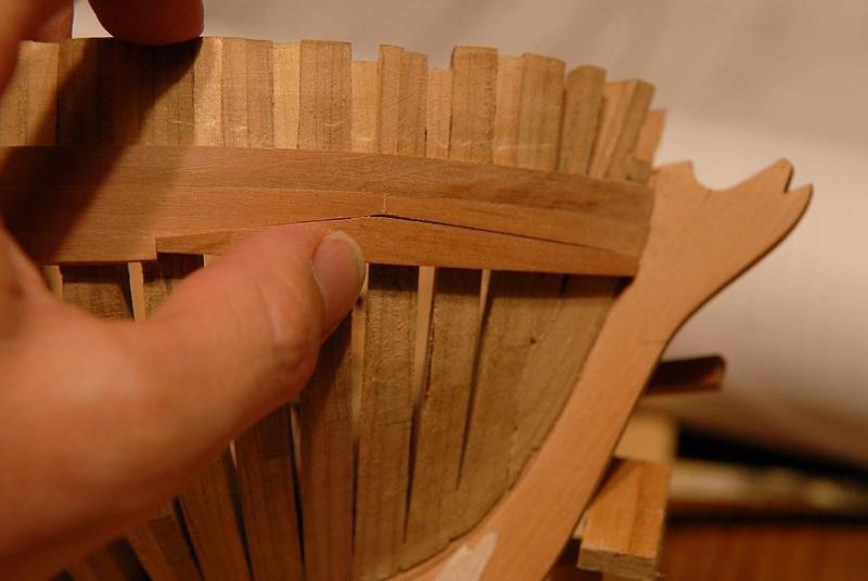
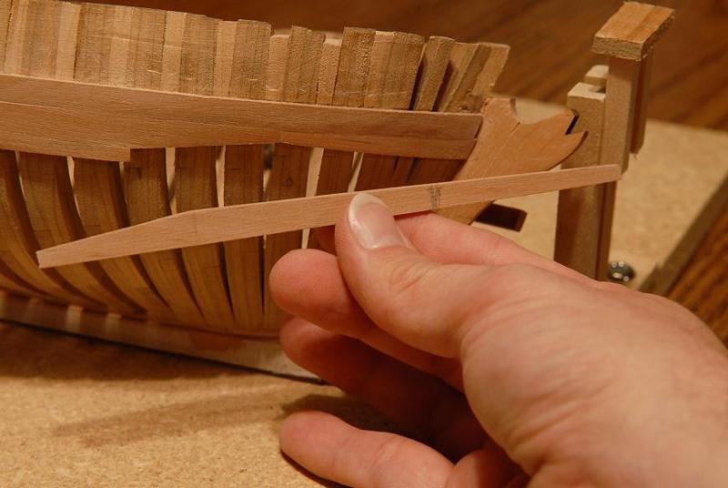
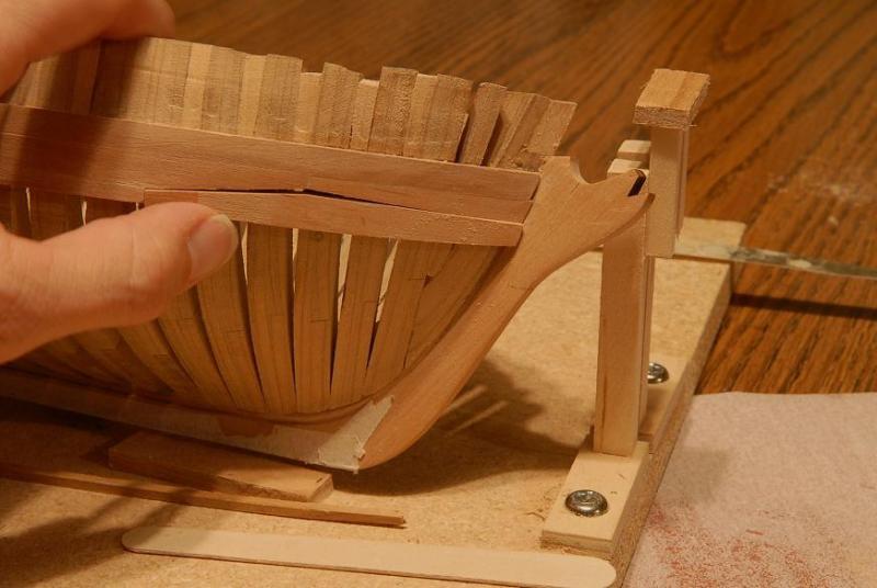
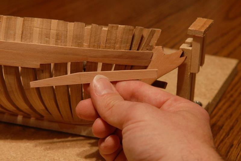
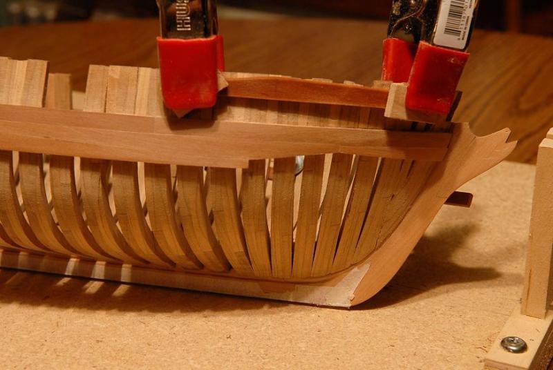
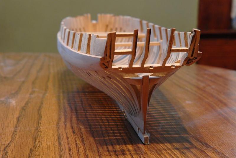
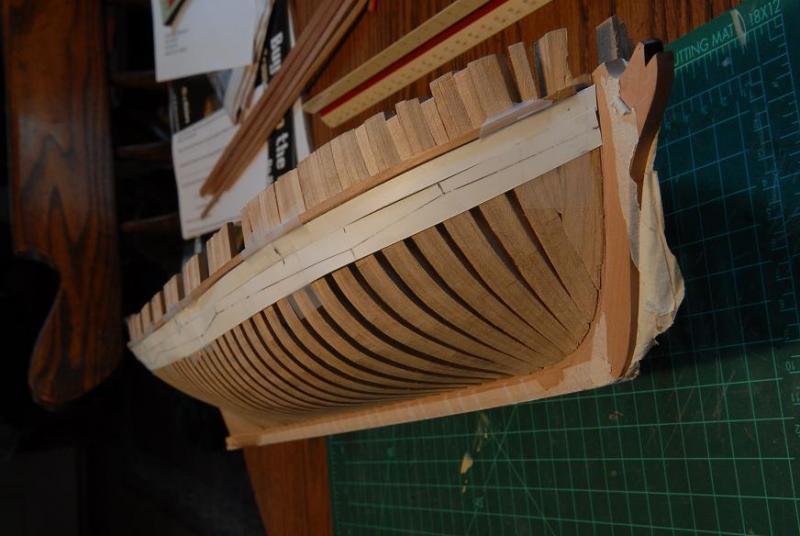
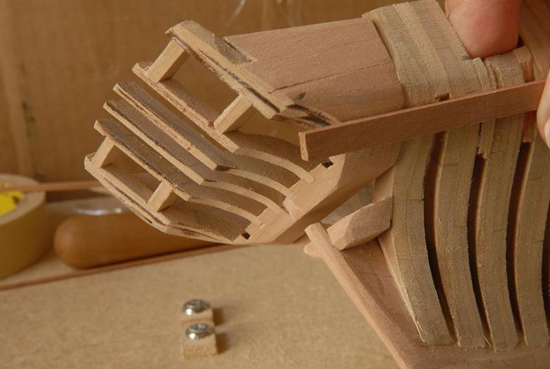
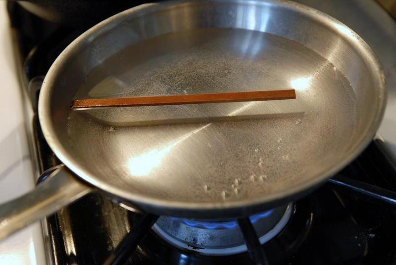
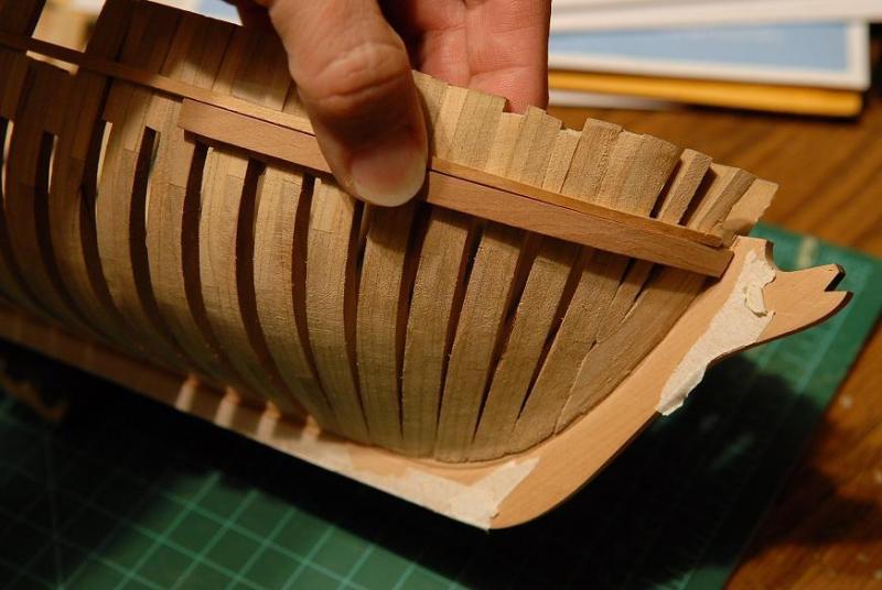
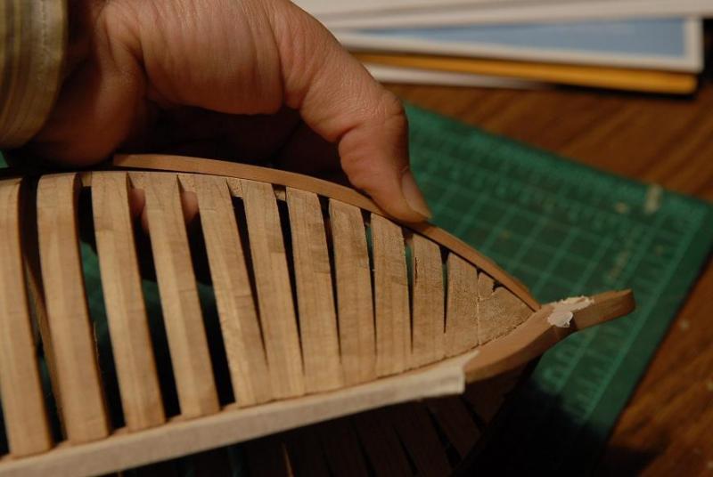
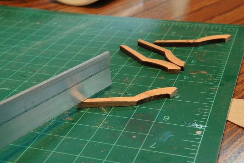
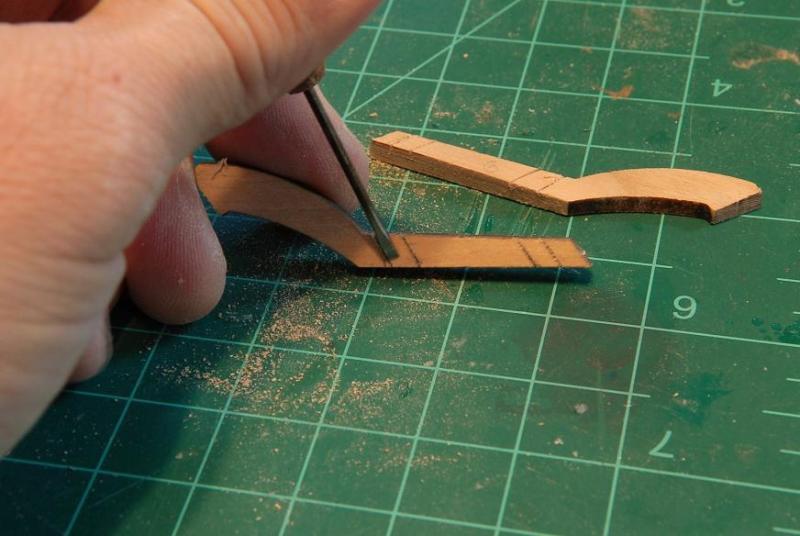
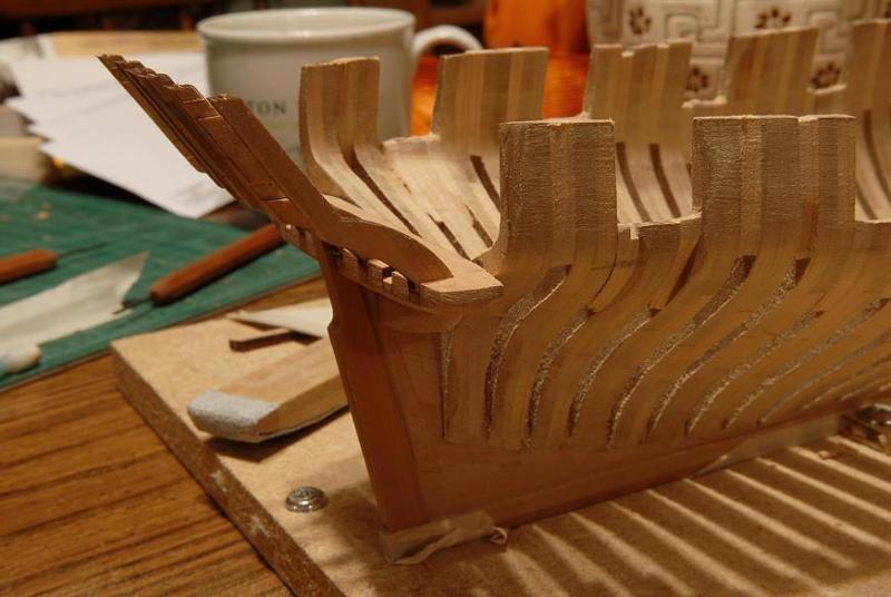
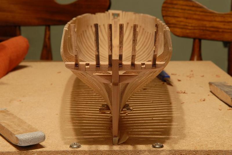
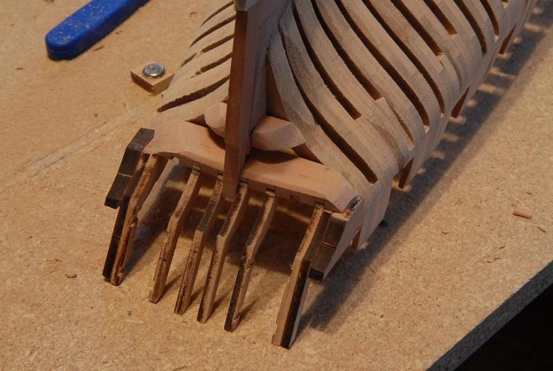
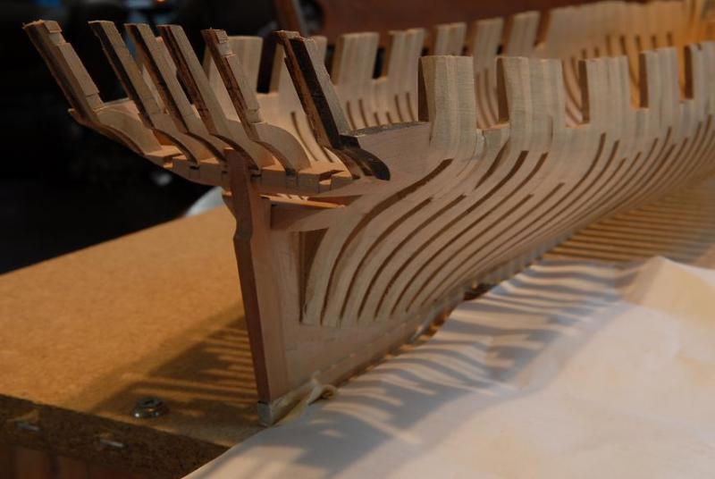
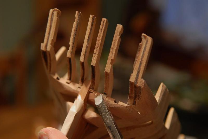
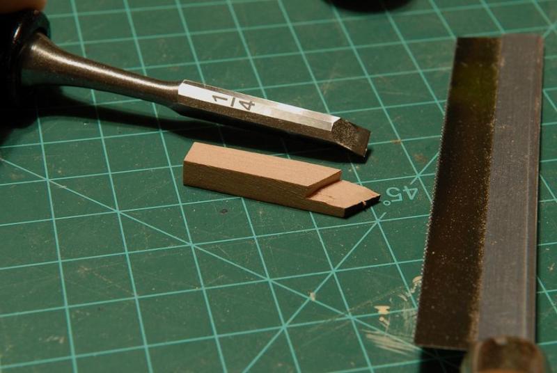
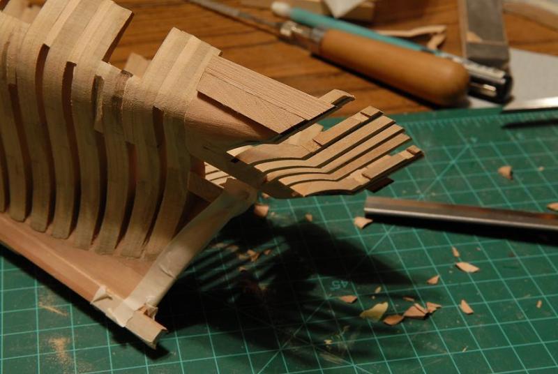
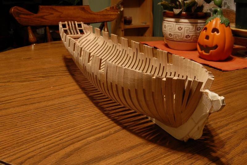
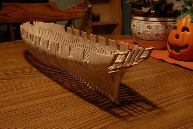
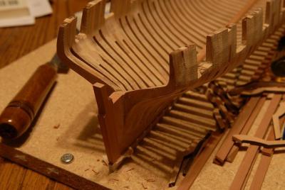
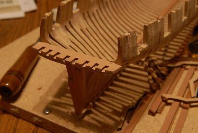
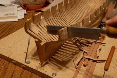
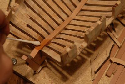
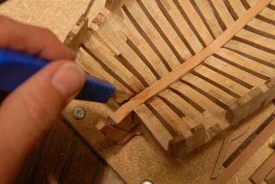
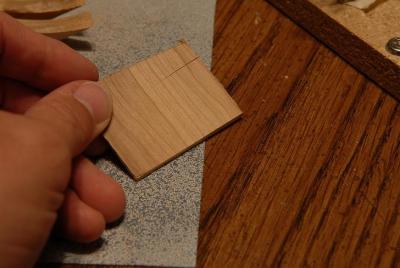
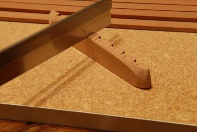
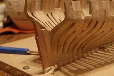
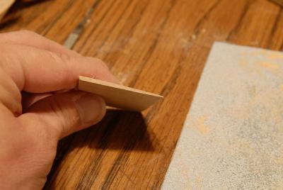
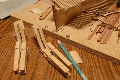
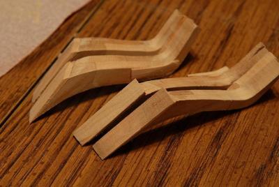
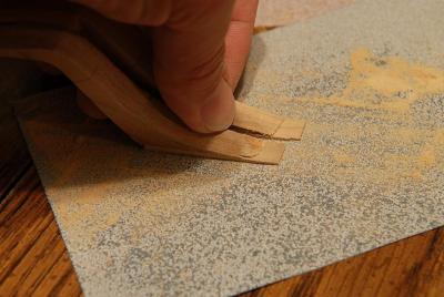
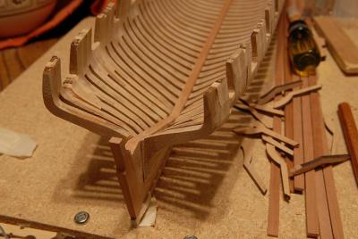
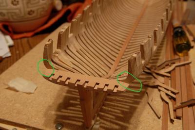
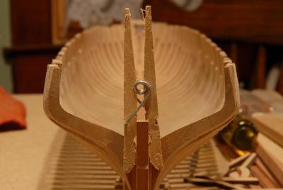
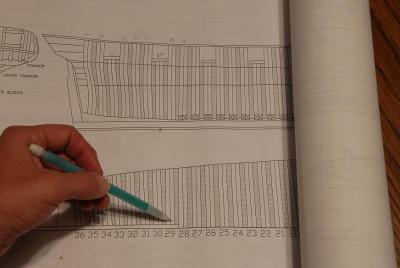
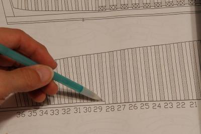
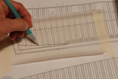
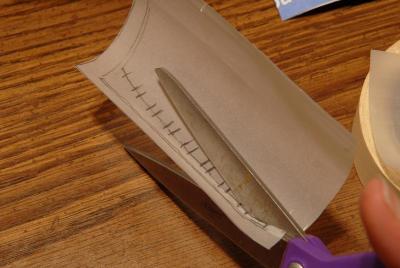
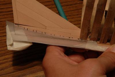
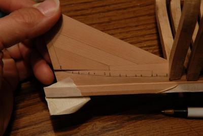
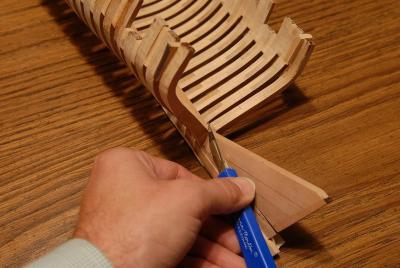
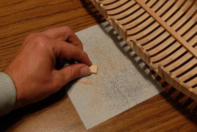
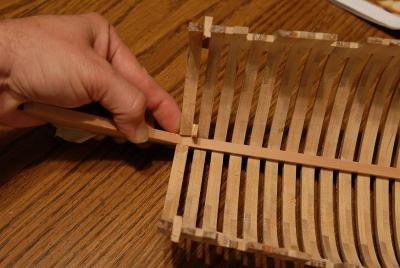
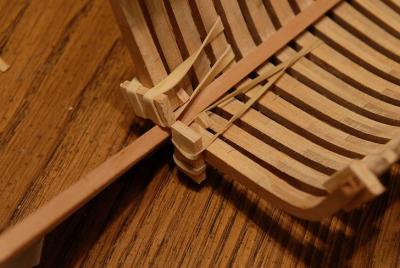
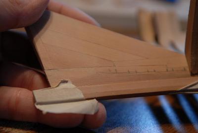
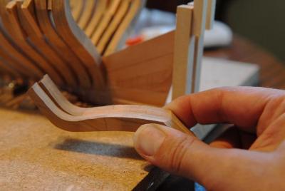
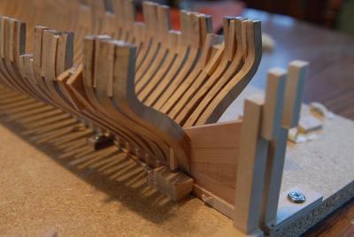
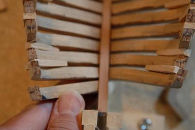
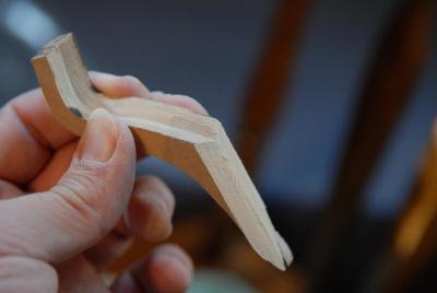
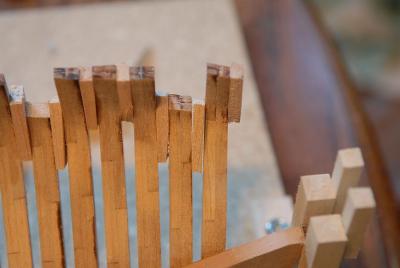
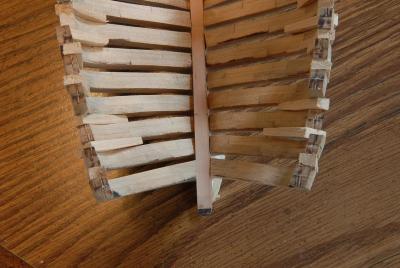
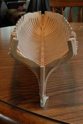
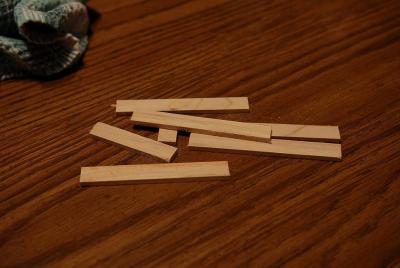
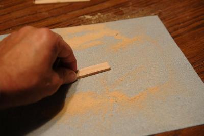
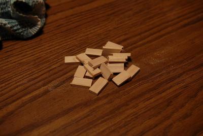
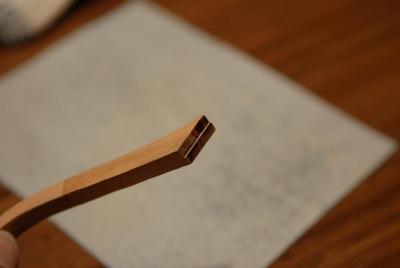
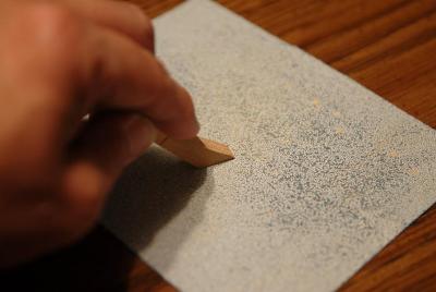
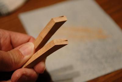
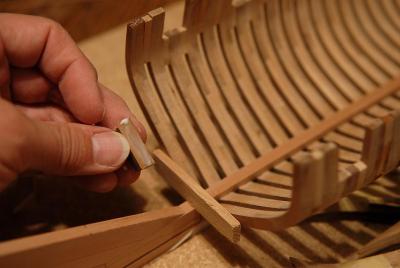
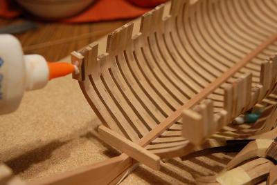
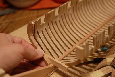
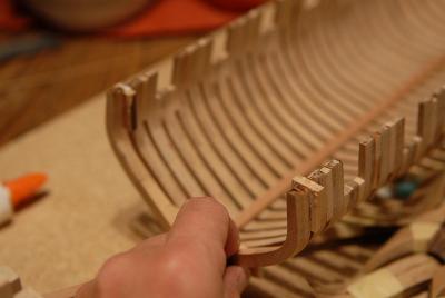
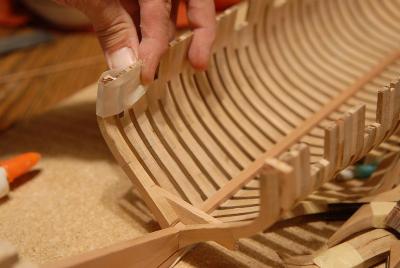
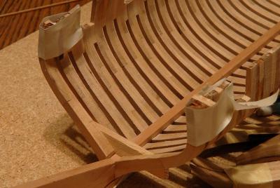
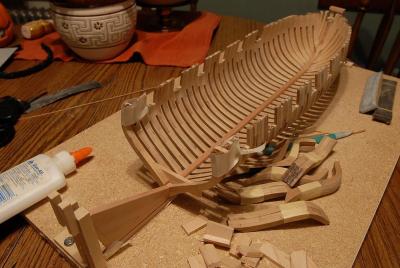
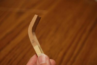
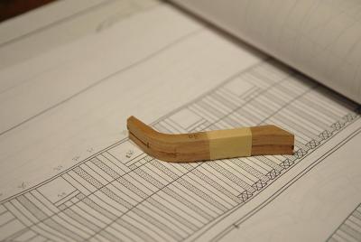
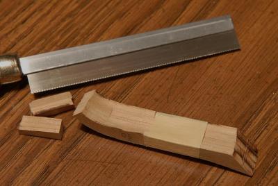
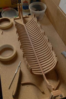
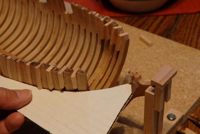
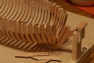
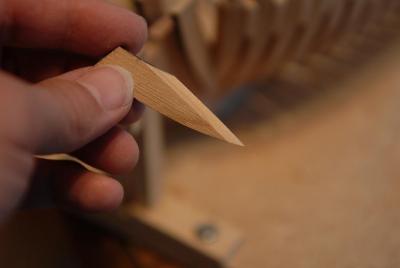
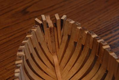
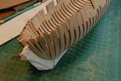
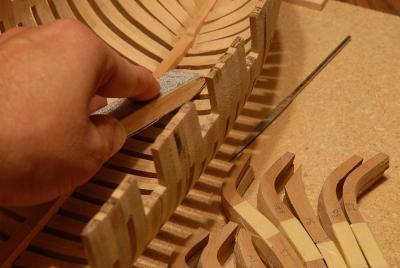
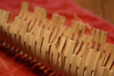
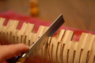
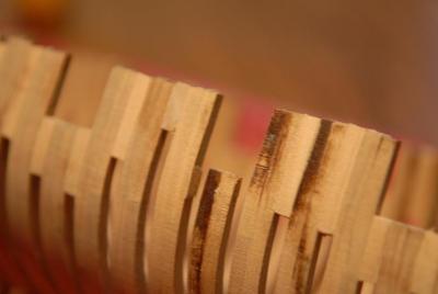
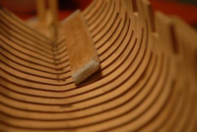
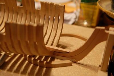
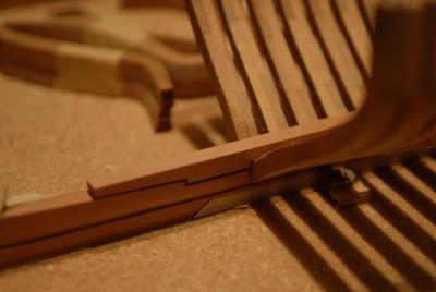
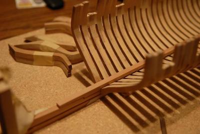
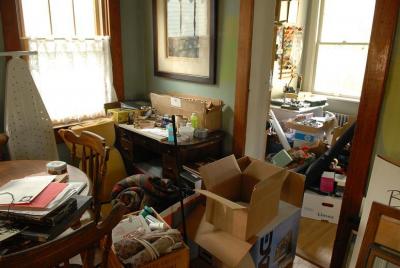
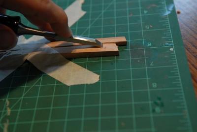
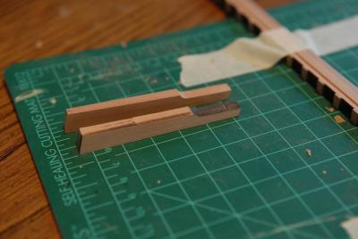
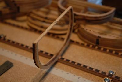
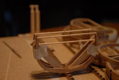
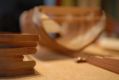
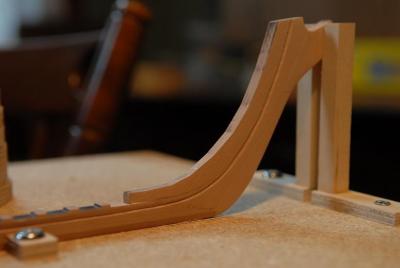
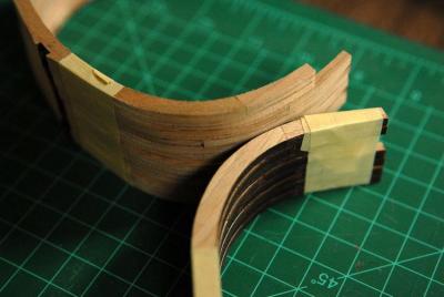
 December 23, 2009 The hull seems very strong and stable now. I tried squeezing the sides together with a hand on each side and it's very stiff. Doesn't give much at all. I squeezed a little harder, but stopped that foolishness immediately when I heard a slight *crack*. I've decided to work on the transom/counter. The pieces back there that have come loose and fallen out over the last few weeks pushed me to tackle that area, and catch it up to the rest of the hull-- I've put the rest of the inner counter timbers in, which will all be covered by planking-- Now for the outer counter timbers, which are very complex and are an important part of the appearance of the transom. First I cut a paper template of the shape-- Traced it onto a block of 3/8" boxwood-- Cutting the pieces out-- These blanks need to be shaped in two directions-- The one in the foreground is about the right thickness here-- It looks about right-- From the stern, you can see the timber needs more curvature at the wale-- So I boiled the piece for about 5 minutes and tried bending it. Still very stiff. I boiled it some more, but it really doesn't want to bend, and I broke it. This is not going to work-- Plan B-glue up a thicker counter timber blank. I had to cut two more blanks from my boxwood block, and another set from a thinner billet to make up thicker blanks-- While I was sanding the first set of blanks, and test fitting it to the hull, I realized I need to cut back the wale about 3/32" at the stern. So while my new timber blanks were drying, I trimmed the wale with a knife and chisels-- Then I started shaping the second set of counter timbers-- After a short while, I realized that my template wasn't quite right, and I didn't have the right angles and curve to ensure a good fit. I had to abandon the second set of blanks and try again. I feel like I'm using up my limited stock of boxwood at an alarming rate. I hope I don't have to do this again! This time I used just a partial piece of the thinner stock to cut down on the amount of sanding-- While these dried, and because I was a little discouraged and tired of sanding, I looked at the stern some more, and decided that it would be okay to plank the counter and transom before gluing the outer counter timbers on. So I glued a temporary guide at the point where the hull and counter planking should meet-- And glued planking on--a nice simple first planking job-- Then I chiseled and filed the ends to a rough shape for the counter timbers-- Next I need to plank the upper part of the transom. I'll also use a temporary piece at the joint between the lower and upper parts, because that piece needs a fancy profile and I'm not ready to tackle that. You can see here the "slot" at the junction of the wale and counter that the doubly curved counter timber needs to fit into. The upper strake of this planked section also has a curve that needs some more fine tuning. The area below the counter looks like it need a good deal more fairing to be right for the hull planking-- December 31, 2009 I have spent a good part of two days continuing my work on the transom. First I needed to edge bend some planking for the upper part of the transom. The curve on the front of my work table looked close enough-- Here is the transom planked. Later I will cut out the two stern ports. They need to be adjusted inward from where the framing puts them (an adjustment needed by my slightly narrow stern). They also need to be adjusted vertically to coordinate with the planking strakes. The kit instructions called for the transom planking to be a few wide planks (about 18" in scale), but I opted for narrower planking that could follow the double curve of the transom-- Next I went back to work on the outer counter timbers. I very roughly shaped the starboard one, and then temporarily glued it on to do further sanding-- Here it is sanded down quite a bit-- A comparison photo of the mostly shaped starboard piece and the still very rough port piece-- After some more shaping of the port timber (I used my rotary tool sanding drum up to this point) here is the comparison of the two pieces-- As I did with the starboard side, I temporarily glued the piece on to do more sanding (now all by hand)-- This is just about right for now-- I removed the piece and here are the two. They are not exact twins, and there is more shaping to be done, but that will wait until I glue them permanently-- Next I iron stained the transom-- And take a breather. I've also cleaned out this room enough that I can now work here instead of the dining room table [That plan didn't last very long]-- Ron
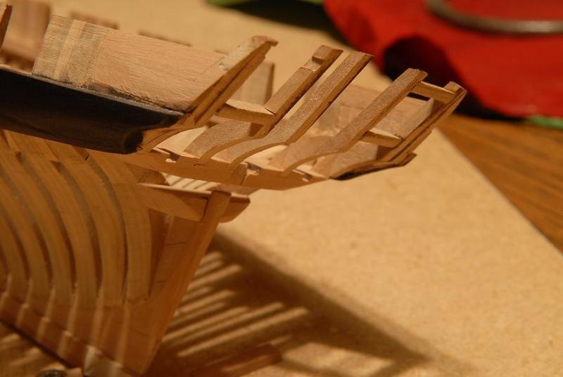


-
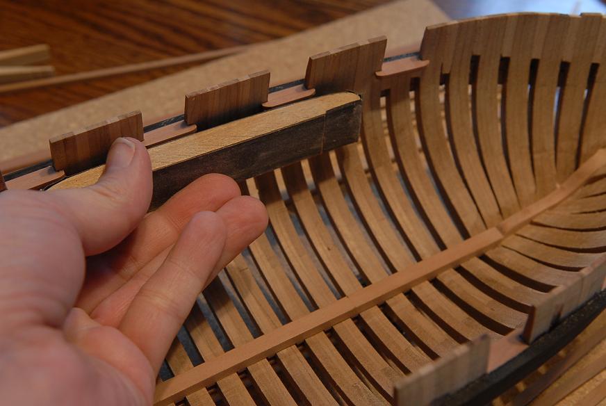
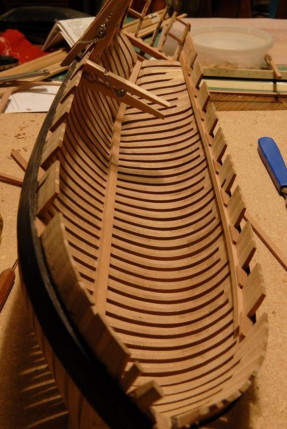
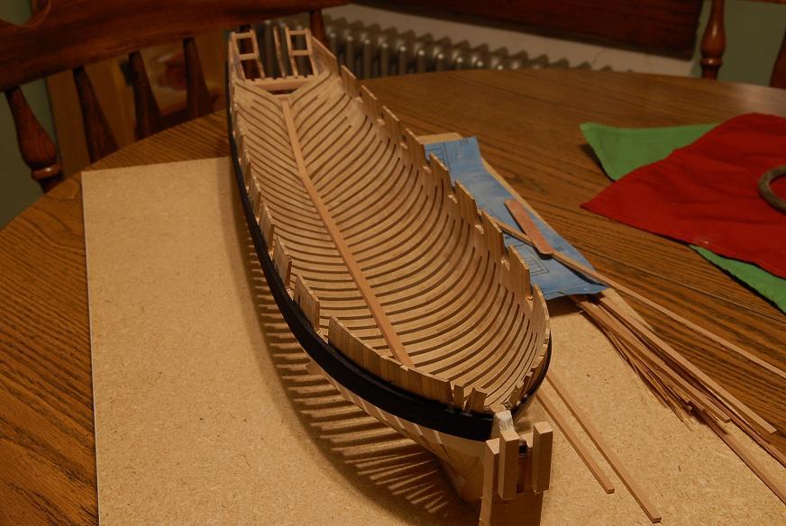
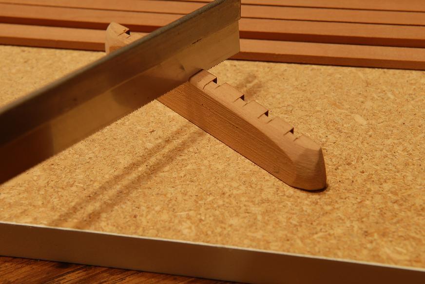
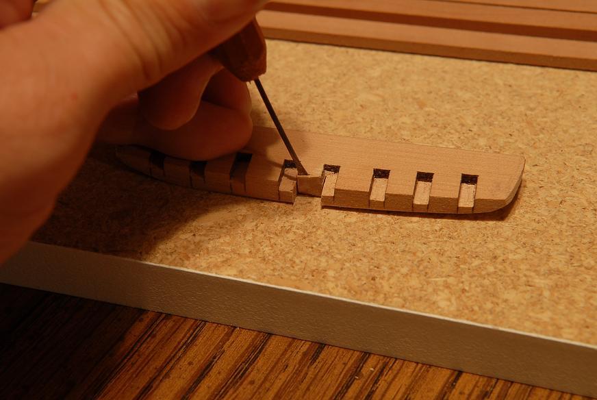
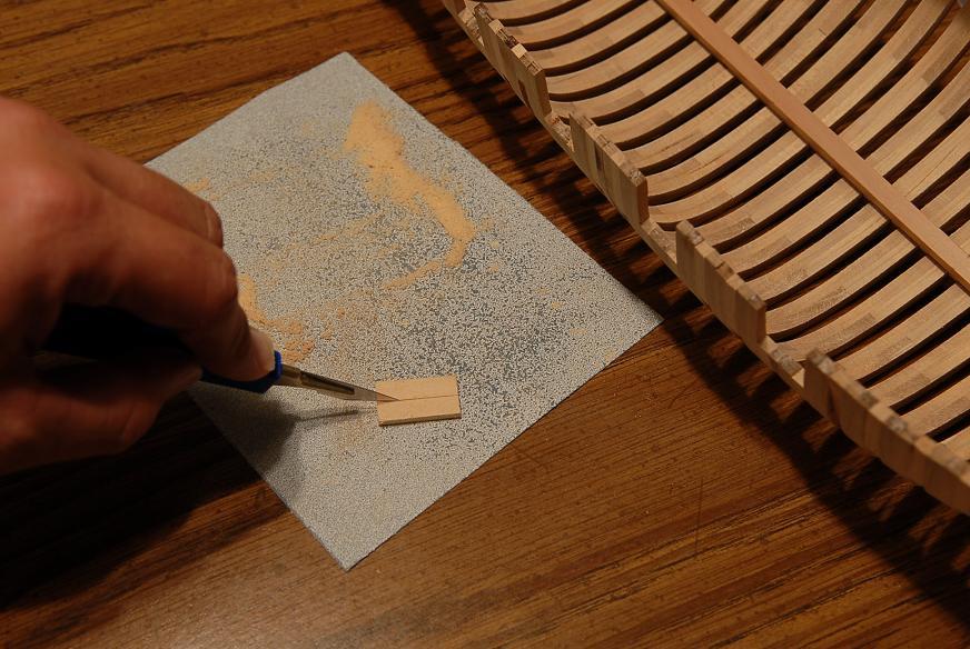
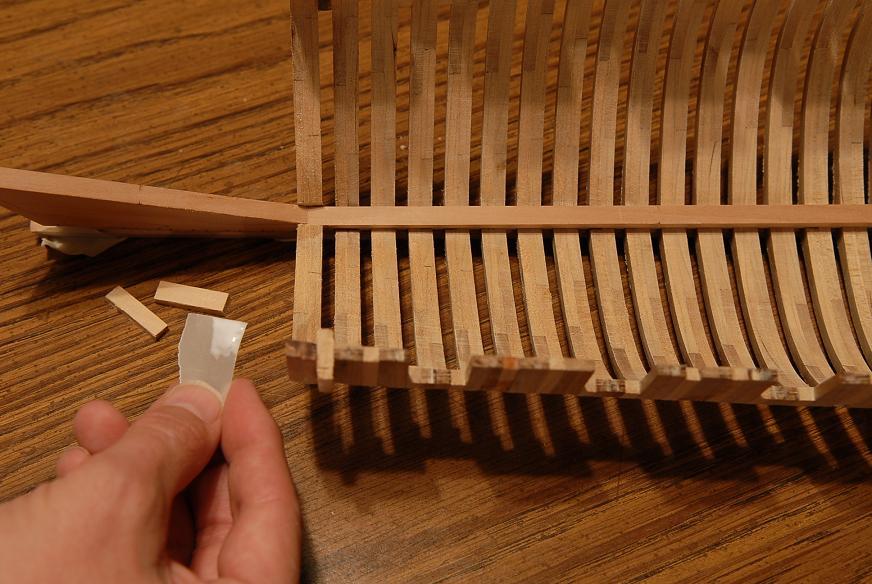
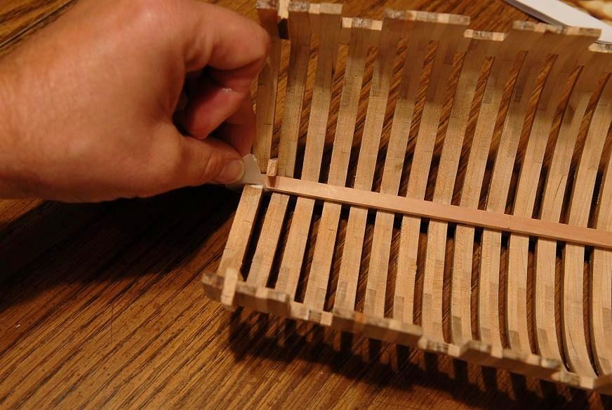
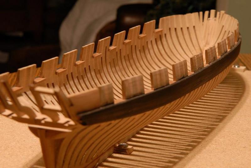
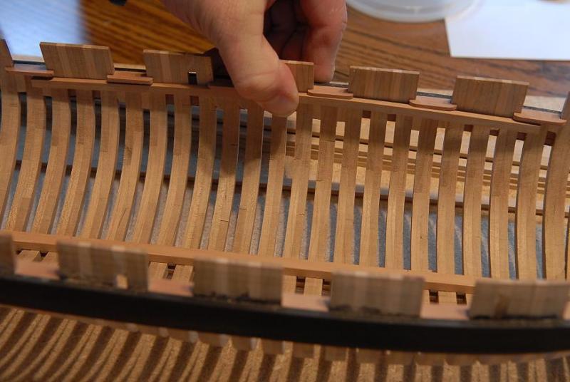
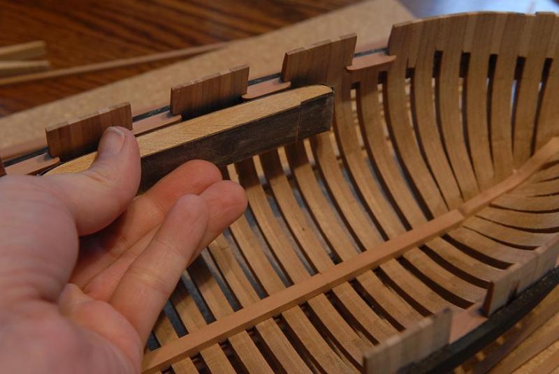
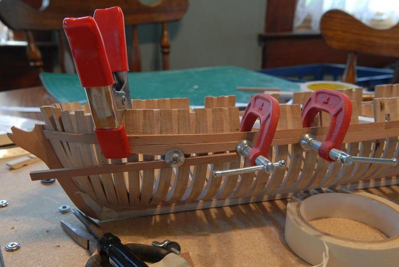
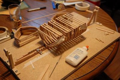
December 16, 2009 The gunport sills have now been glued in. [You might wonder why they were glued now, so far in advance of the deck, waterway, etc. This is clearly not the order that the actual ship would be built. Gluing them now makes it easiest to get good joints between sills, the wale and the waterway. Then the deck can be built up afterwards for good tight fit.] The gunport sills have now been glued in-- I have to think now about what to do next. Probably the deck clamps, which is going to take some studying about what to do at the stern. There doesn't seem to be enough space to fit everything. I think I will need to remove some more material from the aft most frames where the deck beams and clamps are to go. December 20, 2009 There's definitely not enough room at the stern! I'll have to do some surgery on the frames and a little fakery on the deck beams when I get to them. The whole deck will be planked, so none of that will show. I'm going to work my way down to the clamps. The order of construction (on the model, not real practice) is 1)Wale 2)Sills 3)Waterway 4(Deck beam temporary spacers 5)Clamps. Then after the clamps are in, I'll remove the temporary spacers and install the deck beams. At least that's the plan! I'll do each waterway in three pieces. Here's a center piece-- It's temporarily clamped in order to see if the sills need some trimming. They do. The sills should extend just a bit less than the edge of the waterway. [i modeled the waterway and sills to be similar to the replica of Niagara, which I had recently visited. I later saw photos of Glenn Grieco's model of the Jefferson for the Institute of Nautical Archeology, where he had chamfered the waterway in between the sills to a more usual shape. A nice detail that I wish I had done]-- Sanding the edges of the sills-- Gluing the first piece in-- Here's the stern piece being glued in-- And a view that shows the run of the port waterway under the sills-- The bow pieces are next. I think I may need to use a wider piece and sand it down to shape. The cross section should change from rectangular to trapezoidal as it curves forward to the stem. I could ignore this if I was going to build the forcastle deck, but since I'm not doing that, the forward section of the main deck will be visible. December 21, 2009 Here's the work on the bow waterway pieces: First I boiled a couple .125 x .25 inch pieces--the rest of the waterway is .125 x .18 inch, so these are quite a bit wider. Then clamped them to the bow to dry-- I checked them after a couple hours, then moved them closer to the final position to dry some more-- Once dry I was able to sand them to the right width on a piece of sandpaper flat on my table. Because the bend and twist are set, the changing bevel along the top and bottom of the piece took care of itself. The end bevel was more tricky to sand. Here is one piece done, and the other "raw"-- The pieces are dry fit here. They are not exactly in position, when they are the gap at the stem should go away. [it didn't. In my sanding and resanding the bevel at the tip, I made the starboard piece too short. If this was going to show I would redo the pieces, but this joint will be quite hidden by the bowsprit. However, if it ends up being necessary I'll put a little filler piece in.]-- Gluing the waterway piece in-- All done! Ron


-
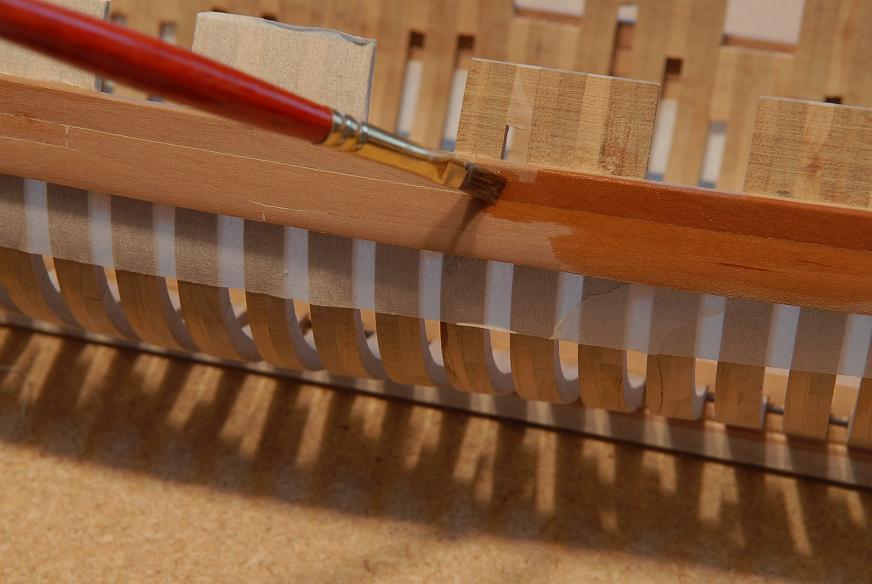
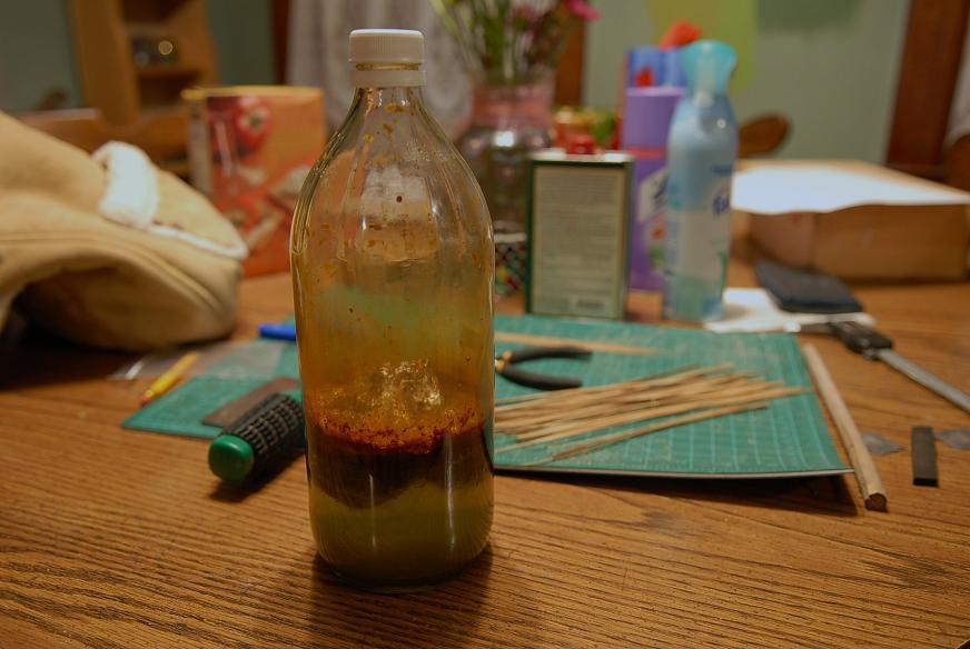
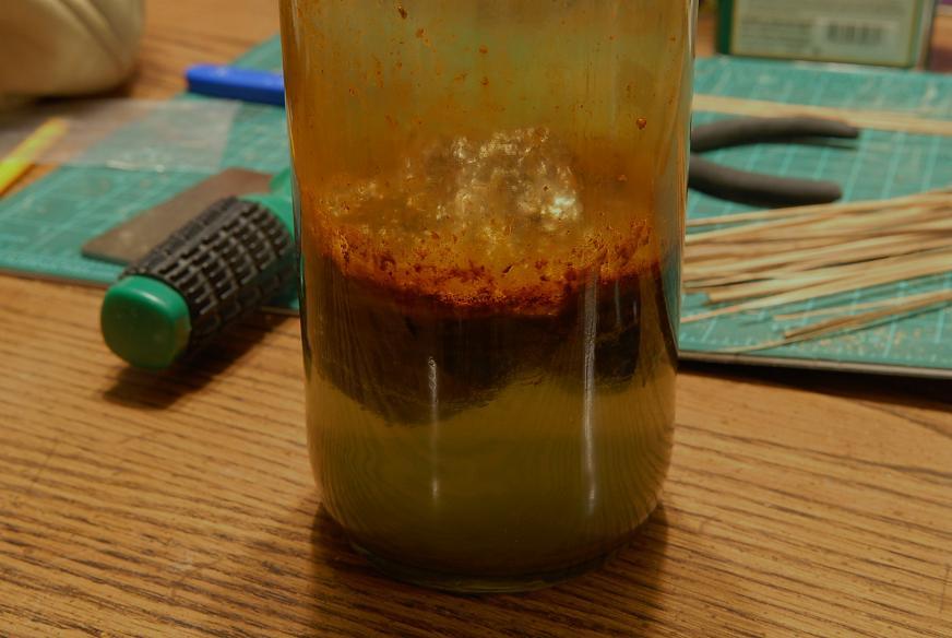
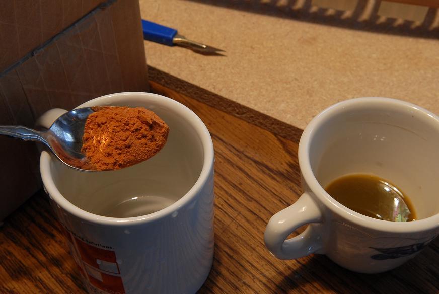
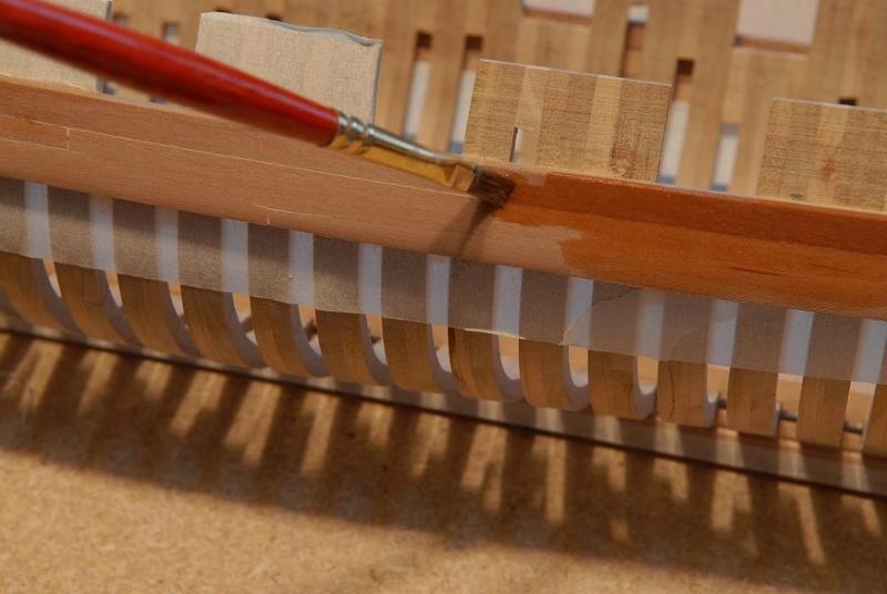
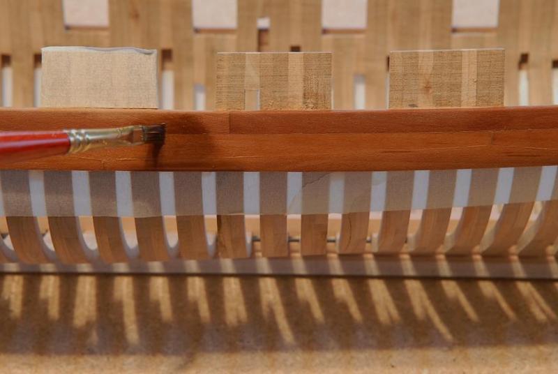
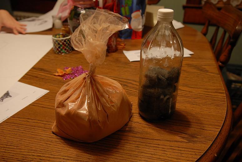
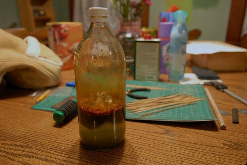
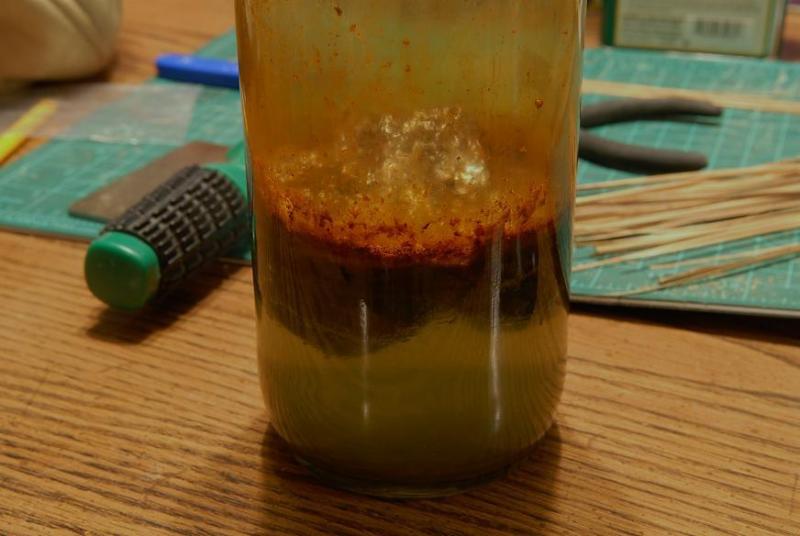
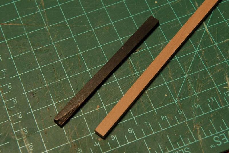
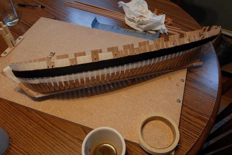
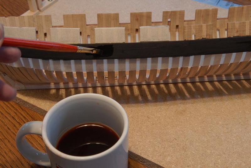
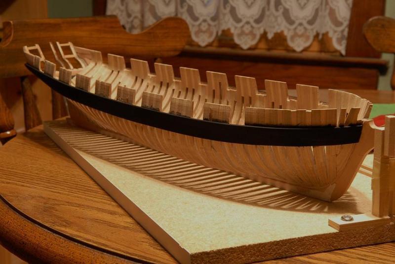
December 2, 2009 I have started a concoction for simulating ebony. I'm very curious now to see how it turns out. [i realize this is a little repetitious since I only recently showed doing this at the start of the new site log--but I included this for the sake of completeness, and these photos showed the process well.] [Also, this seems kind of abrupt in the log since in the last post I was doing gunport sills. I needed to stain the wale black before gluing those sills on.] On the left is a packet of Quebracho Bark powder, ordered from a taxidermy supply website. On the right is a hunk of steel wool stuffed into a bottle about a quarter full of plain vinegar-- I need to wait for the steel wool to disintegrate into rust, then I'll continue. December 7, 2007 Not much happening with Oneida. I wait for my steel wool in vinegar to rust. It looks pretty disgusting-- I feel like a mad scientist-- December 10, 2009 I decided to test the witches brew, and see if it was ready to go-- The result was a very rich black (this also has some Tung Oil Finish on it), so I decided to go ahead and stain the wales. First I masked off the frames below the wale. I suspected that this wouldn't completely keep the stain from seeping onto adjacent areas, but I hoped the tape would help minimize it. The only critical areas are at the stem and on the port side frames which I hope to leave exposed below the wale. If there's too much seepage, or it can't be removed I can put a strake below the wale to cover any staining on the frames-- Now, here's the procedure: First I strained some of the steel wool/vinegar into a small cup-- Then in another cup mixed up some Quebracho bark tea-- Here are the two mixtures ready to go-- First the wale needs a complete soaking with the bark tea. This took a couple of passes to make sure the wood had absorbed enough-- After letting the wood set a little (just so the tea is soaked in and not standing on the surface), the iron stain is painted on. It goes on just barely darker at first-- But within a minute it starts to turn black-- And after about 5 minutes, the time it took to paint the sides, top and bottom of the wale, it turns completely black-- After this dries--the wet black turns to a slightly lighter flat tone--it is washed again with the bark tea-- This deepens the black, and it's done-- The port side wale (which I had done this afternoon) has now had a light sanding and light initial coat of finish. I won't do any more finishing than this because I'll probably need to glue things to the wale-- Is it any better than just painting the wale? I think it does look better. It's black without covering the grain--which shows if you look close. I can't say how close it is to ebony, I don't have any. But it's definitely black. And hopefully it won't disintegrate the wood or glue. Time will tell. Next is finishing the gun port sills and gluing them on. Ron


-
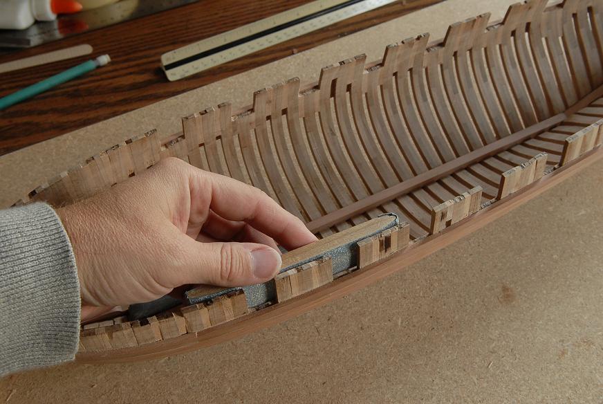
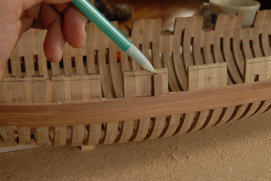
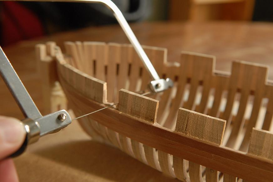
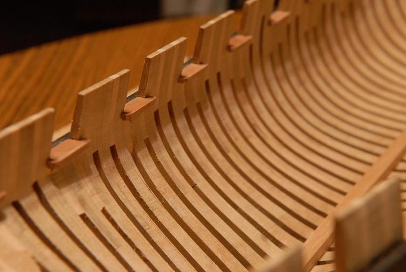
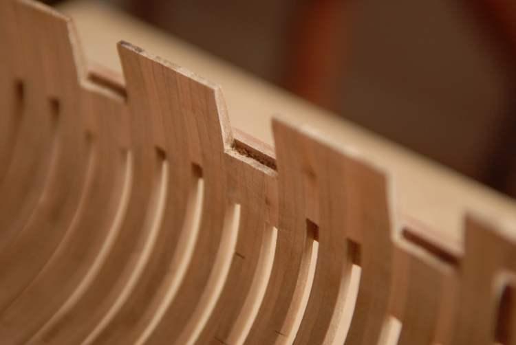
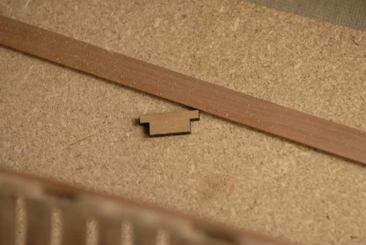
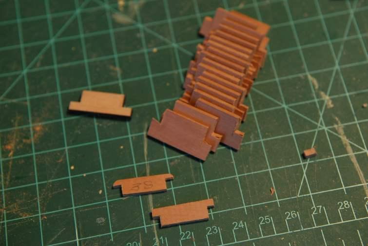
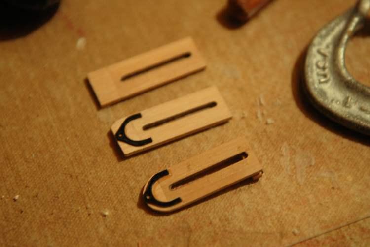
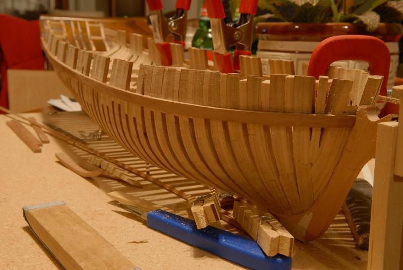
November 15, 2009 I could go a number of different directions now. The Lumberyard instructions are listed by topic, i.e. "Building Frames, "Counter Timbers", Wales". However they are listed alphabetically and not in building order. So you have to look at everything (which is a good idea anyway) before you know what to do next. At this point I could work on the decorative fashion timbers and the transom planking, or I could work on the port sills followed by the deck clamps, or even the bulwark and/or hull planking. I've decided to do the gunport sills and deck clamps, to further strenthen the hull. First step now is to sand the bulwarks down to final thickness, which I can do with much less trepidation knowing the wales have added strength to, and helped stabilize, the hull. I took the temporary deck beams out and am now sanding away-- While I was sanding the bulwarks I thought I better see how high they really are supposed to be. I was surprised at how much taller they were than they needed to be. I cut a spacer piece and slid it along the top of the wale, marking a consistent line at the correct bulwark height-- Then I carefully took most of the excess off with this dangerous tool-- And hand sanded down to just a little above the line-- I also made the decision to go ahead and cut two new forward gun ports. I'm going to supply the ship with two long six-pounders instead of the long 32 pounder on the pivot. It's doubtful the ship was even built with the forcastle deck and 32-pounder. Possibly I will still build the 32 pounder, and forcastle deck, and display the big pivot gun on its own on the display base board-- November 28, 2009 Today I finished sanding the bulwark thickness at the bow-- Next I went along the hull, and with a small chisel cut down (where needed) and evened up the framing at the bottom of the gunports so the sills would fit-- Now I have to cut replacement port sills. I want to use pear instead of cherry, and they need to be about 1/16th inch thick instead of 1/8th. I'm stealing a piece of the wider hull planking strips to cut the new port sills [some things don't work out right if you mix woods on the Oneida kit, because of which particular billets various pieces are located. Not a big problem though, and in this case I needed thinner sills anyway because of my carronade modifications]-- Here are the rough cut sills, along with the kit piece, and a new shaped piece-- Here is a the shaped sill dry fitted. It sits flush with the top of the wale. In the photo you can't see the joint between the sill and the wale. The gap on the right will be covered by the bulwark planking-- Ron


-
Hamilton, Your Glad Tidings looks great! I think you could do the Hannah! Ron
-
Thanks, hamilton. Your list of previous builds is pretty impressive! It's going to take me a while to finish with the old log. Glad to have you following along. Cheers, Ron
-
Thanks, Elia. My memory is that the top and butt portion of the wale planking went pretty easily with the pre-shaped planks, for most of the length. All except the forward-most and aft-most required only minor fine-tuning. As with all planking, I sanded a bevel on the edges of the planks to eliminate any gaps as they "turned" on the vertical curvature of the frames. The end bow and stern planks required a lot of work, and on those the pre-shaped planks were only a small benefit. I also had to fine-tune some planks to gradually decrease the overall breadth of the wale as it approached the bow and stern. Although I haven't tried it the other way, (measuring and cutting each one individually), I would without hesitation do it this way again. Ron
-
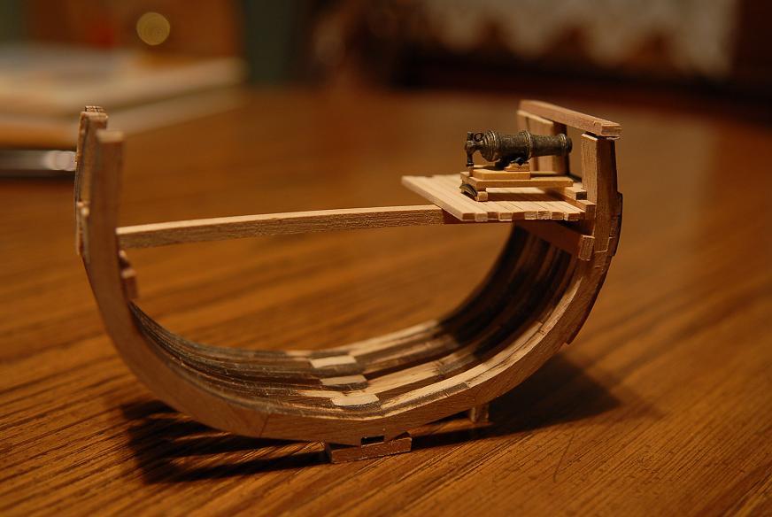
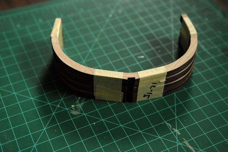
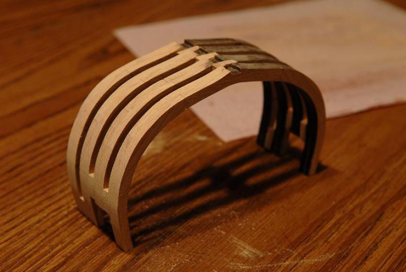
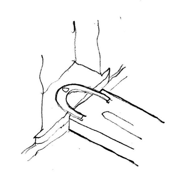
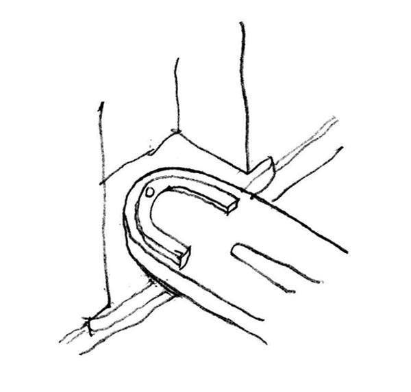
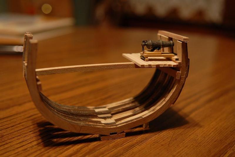
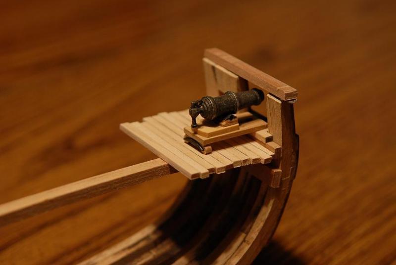
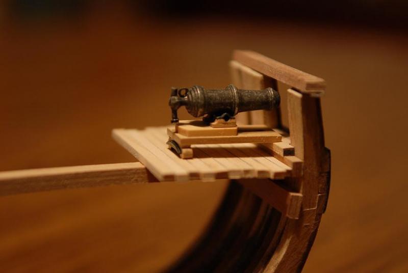
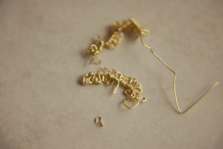
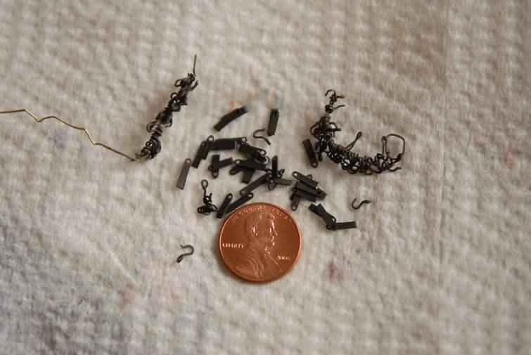
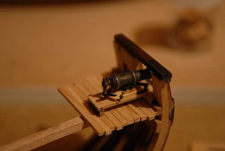
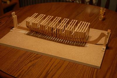
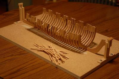
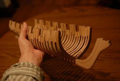
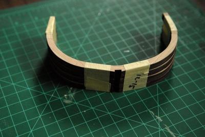
[The dates are going to be out of order for this and the next post. I decided to group some common areas of the build together, even though they didn't happen in chronological order] November 14, 2009 Remember those erroneous beech frames I had in my kit? It dawned on me that I could use them to build a small hull section model to test some finish ideas, try out the adjustments I'm thinking of to the sills and waterway to get the carronades to sit lower, and develop some of the other skills I'll need to finish the model-- I glued them up with some spacers. this doesn't have to be perfect, it won't be to show (except to you all!)-- Then I sanded one side-- I glued up the wale and some planking. I tried out an ebony stain on the wale. I thought this might be nicer than painting it opaque black, but I'm not sure. I think it at least needs another coat of stain-- I also tried my hand at treenails for the first time. I like the silver wire that some modelers use. But the jury is still out on this idea. The real ship used iron fasteners, so I don't want to use wood. Some type of black metal might be better. Is there a kind of wire that is black all the way through? [i never found any]-- I also tried out some finishes. First I used a wipe on polyurethane, and I wasn't sure I like it, so I sanded it off and put on some of the Formby'sTung oil finish (it's not real Tung oil) that I used on my last model. I think it looks better than the poly. (Sorry, I don't have a picture to compare the two.)-- Here's the hull section next to the unfinished wood of the full model-- [A multi-post discussion ensued about modeling treenails, real ship buidling materials circa 1810, and various considerations regarding making historically accurate models. I ended up using bamboo treenails.] November 17, 2009 I've done some more work on the hull section mock-up. This time, I wanted to take a look at the carronade height adjustment. To review my problem, the pieces in the kit are made to attach the carronades as shown below-- I've determined that this isn't really right, and that the front edge of the carronade slide should rest on the sill more like this-- That means some adjustment to the heights of many parts (sill, waterway, carronade parts) will be necessary to make this work. For a first pass at it I: cut the sill height from 1/8th inch to 1/16th inch (6" to 3" in scale), cut the waterway from .2 inches to .18 inches (Too lazy to do the math for the scale sizes there), and as shown earlier in this log, adjusted the carronade lug placement. The result is not too bad. Keep in mind this is very rough, and the purpose is just to see the vertical height relationships. I will add a semicircular front to the carronade slides. For this mock-up I tried the deck planking with black construction paper for the caulking-- Looking at the photos really helps. I think I can shave a little more off the sill, and possibly off of those small wood supports for the carronade lugs. I think I can also shave some off the upper part of the carronade slide truck assembly to make it more level. The first photo shows it best--the rear is just a little high. November 28, 2009 Hello all! Happy thanksgiving. I'm visiting my parents in Rochester, NY for the weekend, and I have brought Oneida and most of my modeling tools and supplies with me. While my mom works on making lace, I have been bending wire for hooks. Here are 72 hooks that I will need for the carronade tackles-- After I bent these, I blackened them along with some other parts I had cut out of brass previously-- Here is the carronade carriage with an extension added, the "iron" piece glued on, then the extension filed round-- And I then assembled a prototype carronade. I think it's going to work out well-- I'm waiting for some supplies to do some more experimenting with staining the wale to look like ebony. I found a recipe on the internet and I'll try that in the next week or so. Ron

-
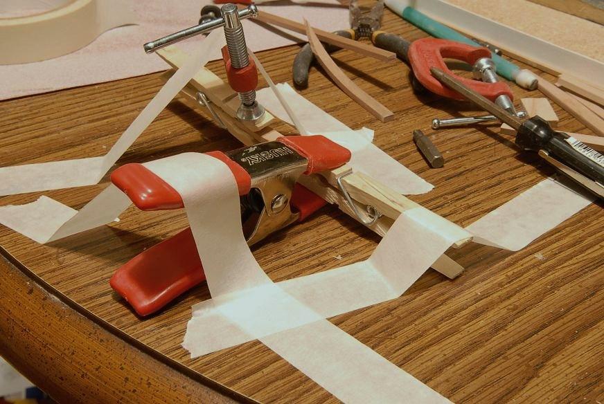
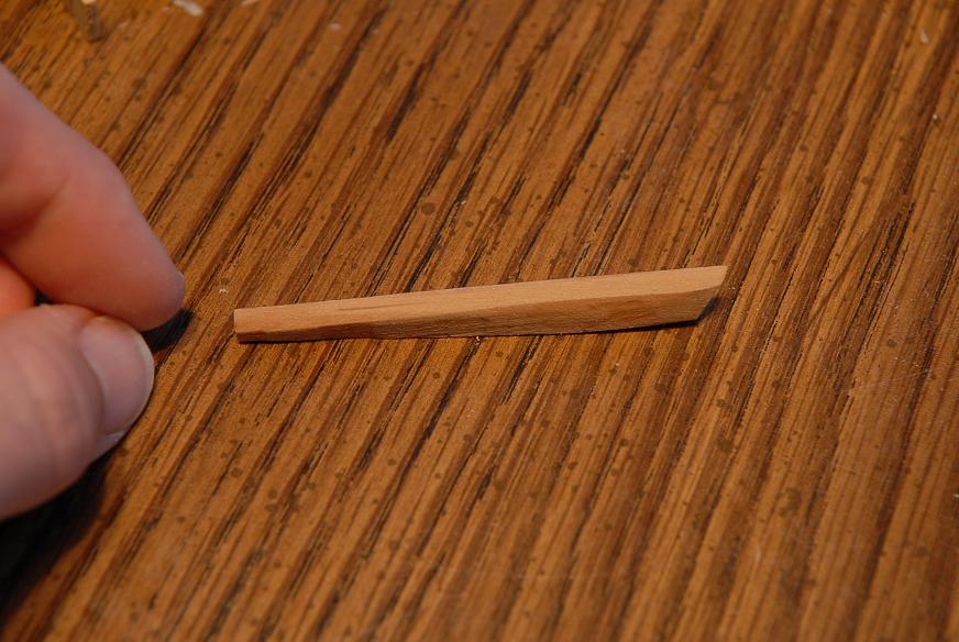
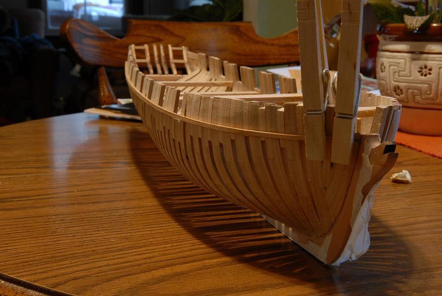
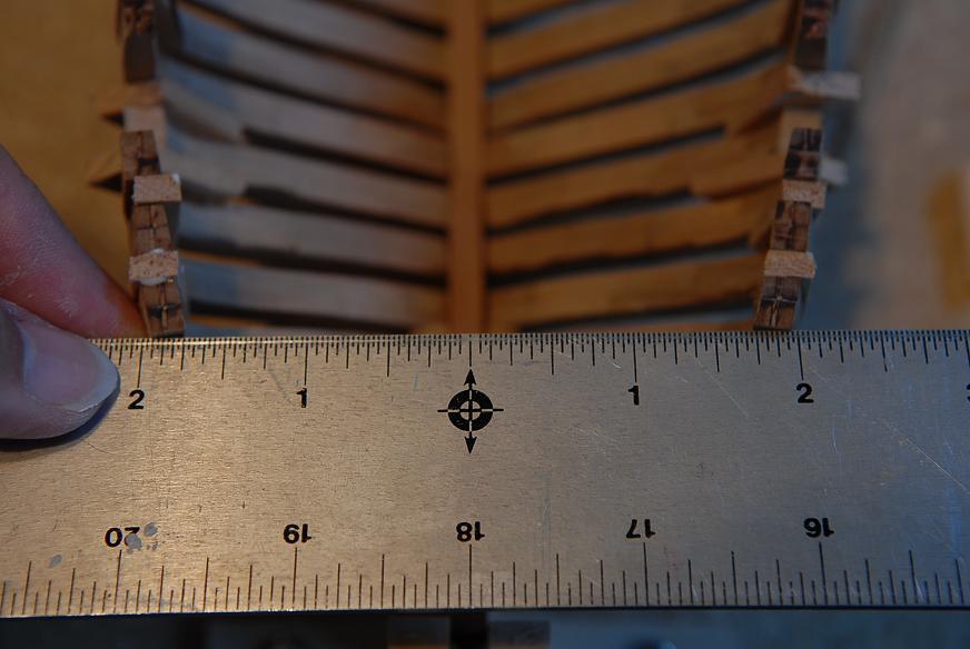
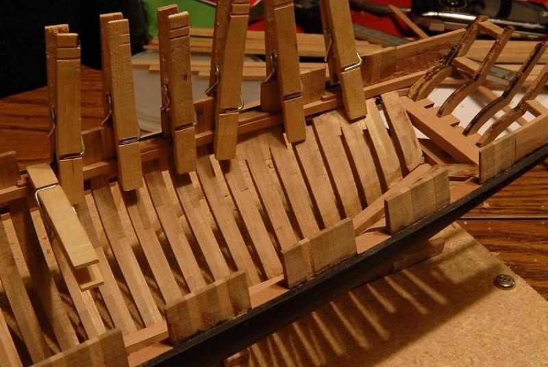
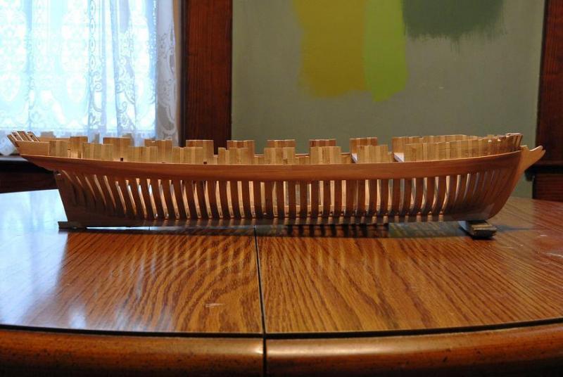
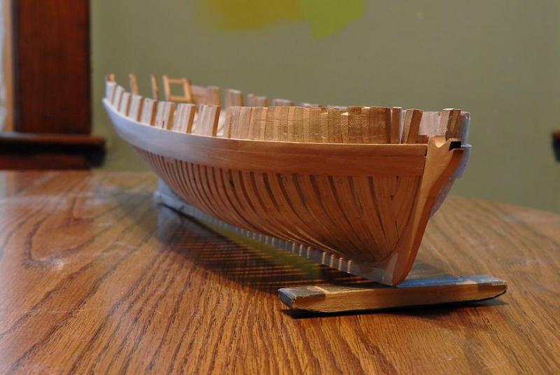
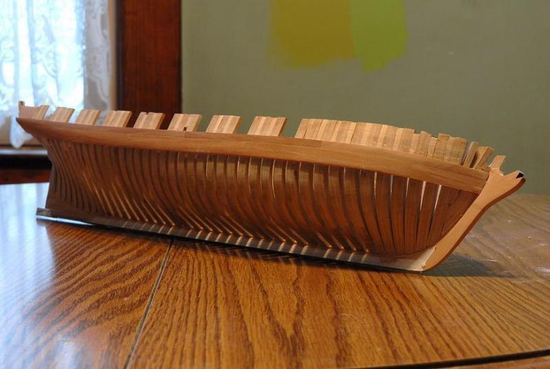
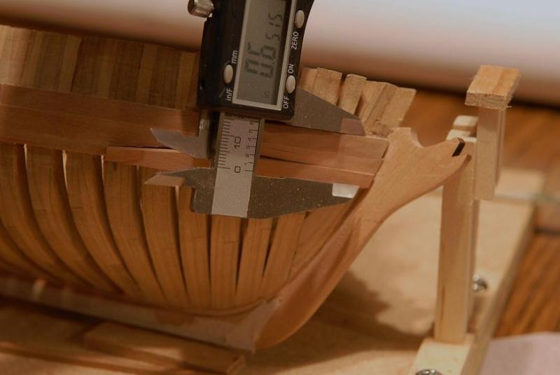
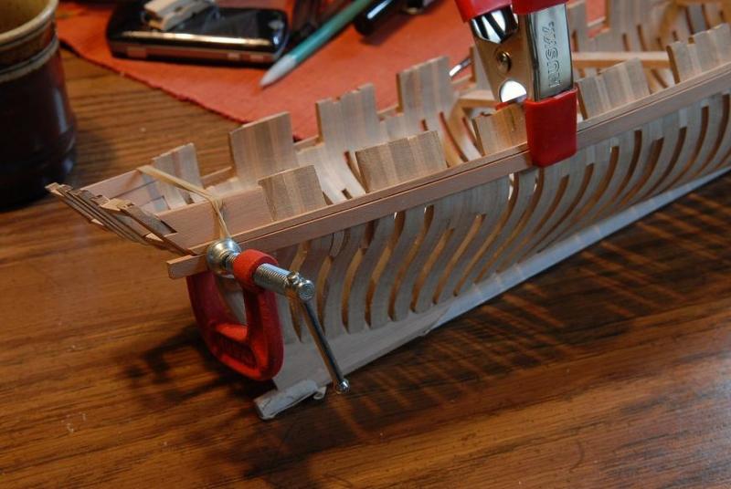
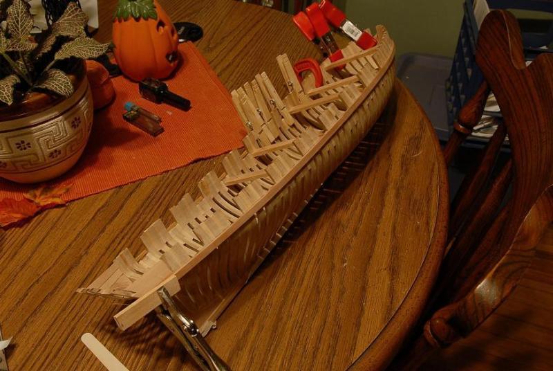
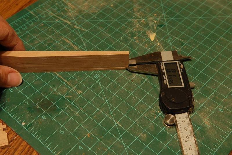
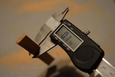
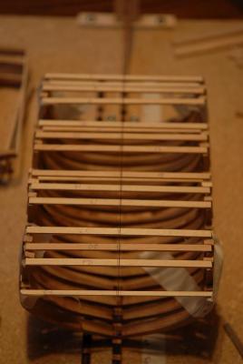
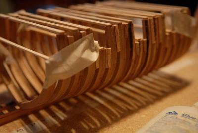
November 8. 2009 I am gluing the wale planks on. I'm working both sides. Here are some photos of some of the wale planks being glued on-- The bow planks I am boiling, clamping on the hull to dry, and then gluing-- The stern-most planks are very tricky--they need to twist a lot. Hard to tell what's happening in this photo, but there's a plank somewhere in that mess of tape and clamps that's being shaped-- November 8, 2009 This is a very funky stern wale piece. It's the one I had to tape down to get it to dry twisted-- Here's a piece glued on, but not a good enough fit-- I took it back off to work on some more. I adjusted the amount of bevel on the top-- It fits better here-- This shows how extreme the twisting is at the stern. This piece I didn't pretwist. The clamping did the job. Just above the clamped piece at the aft end is the small piece I showed at the top of this post. You can see two clamp marks (from when it was wet) on it. They'll get sanded off-- Here's a bow wale being clamped on wet to form the shape-- After it dried, here's the same piece being glued on-- Here's the current state of the starboard side. I've lightly sanded the wale, sawdust has filled in any minor gaps, and you can barely see the plank lines-- Those that know what they're looking for can spot a major goof up here. But to fix it would have meant recutting a bunch of the wale planks. I decided not to do that, which means I'll need to "cheat" a little on my treenail lines. November 12, 2009 I have one more piece to add to the starboard wale, and it will be done-- I had heated and curved the piece, now it just needs to be given a final trim and shape-- I trimmed the end, a little at a time-- Sanded a taper to the thickness-- And adjusted the angle-- Length good. Angles need more adjustment-- I also checked the overall width of the wale. The caliper is set to the dimension from the original drawings--not the Lumberyard plans. Still need to take some off the width-- This is looking pretty good, but I think I can get it better-- Aghh! Too much! I still don't have the middle gap closed, and now the aft side is too narrow. This piece is trash-- I took another piece (which means now I have to cut a new one for the port side)-- Roughly trimmed it-- Boiled and clamped it to the hull. The curve is probably not exactly right where I have clamped it, but it'll get me close-- So I have to wait to finish the starboard side while that piece dries. Might as well glue another plank on the port side. This one's easy-- November 14, 2009 Here are the wales-- The hull is propped up under the bow to approximate the right amount of keel "drag"-- I could have done better on some of those joints at the stem, but I'm hoping they will be mostly covered by the head rails, rigging, etc. If it still bothers me at that point I"ll fill them in [Ha ha ha, right]-- That last picture really makes the wale look like it bends every which way! Ron


-
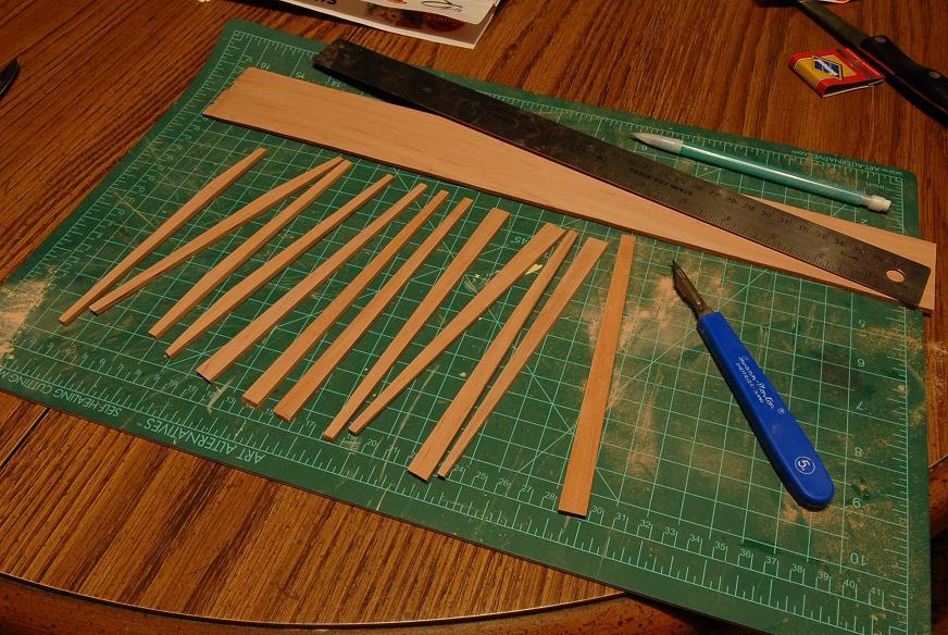
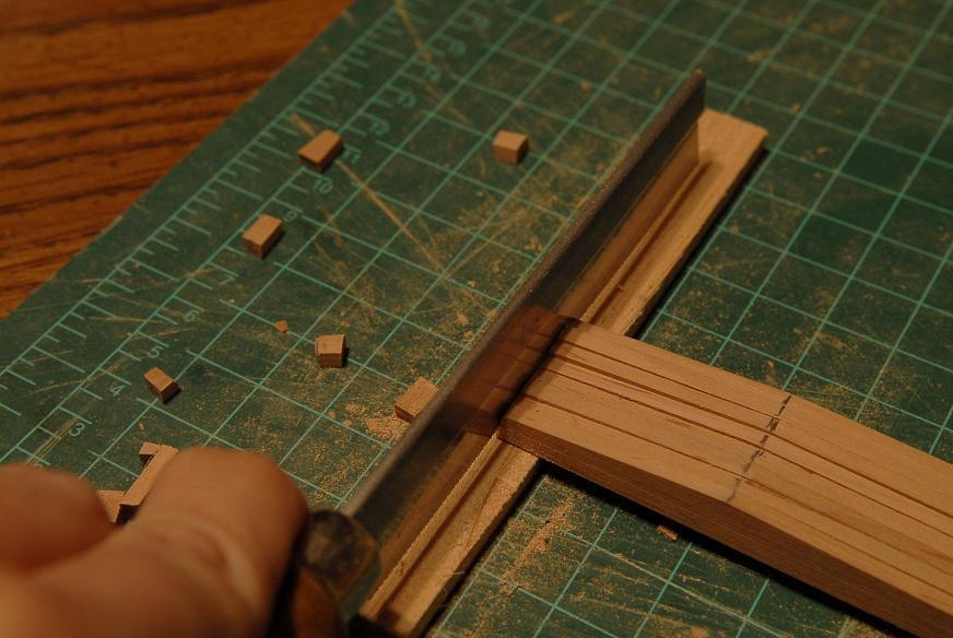
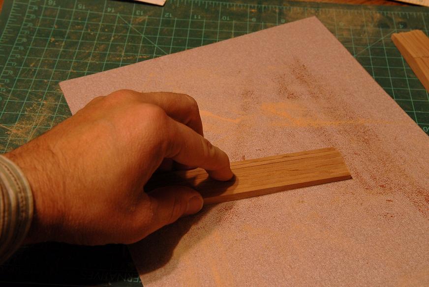
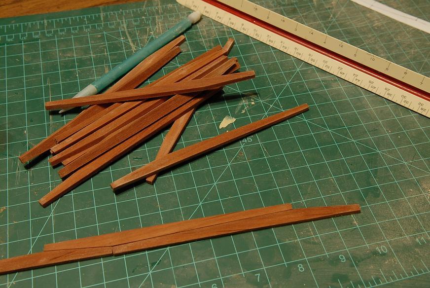
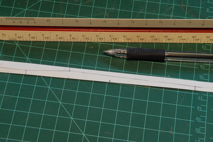
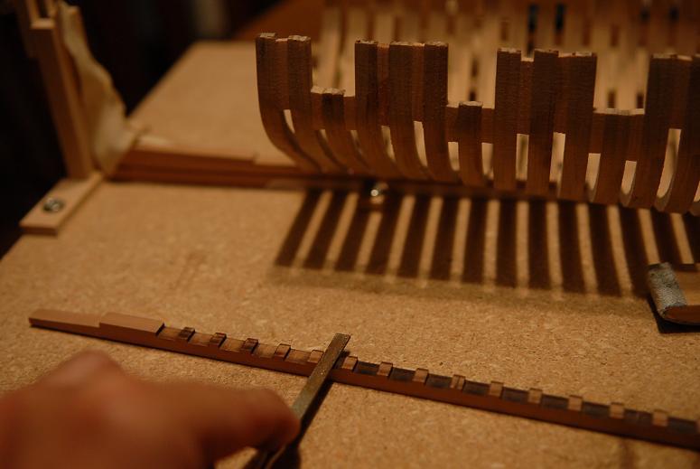
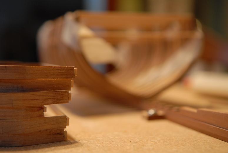
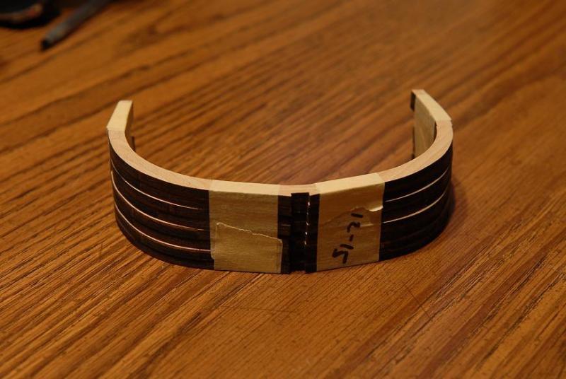
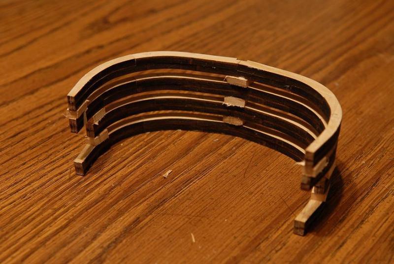
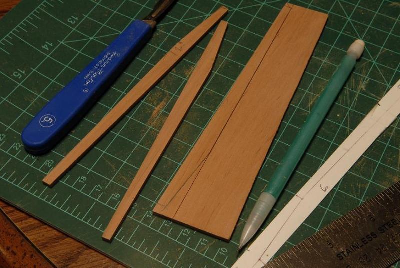
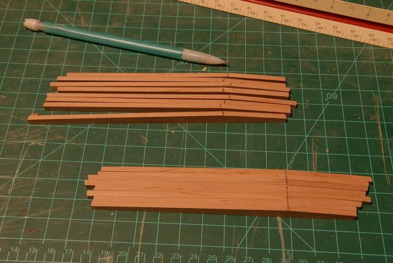
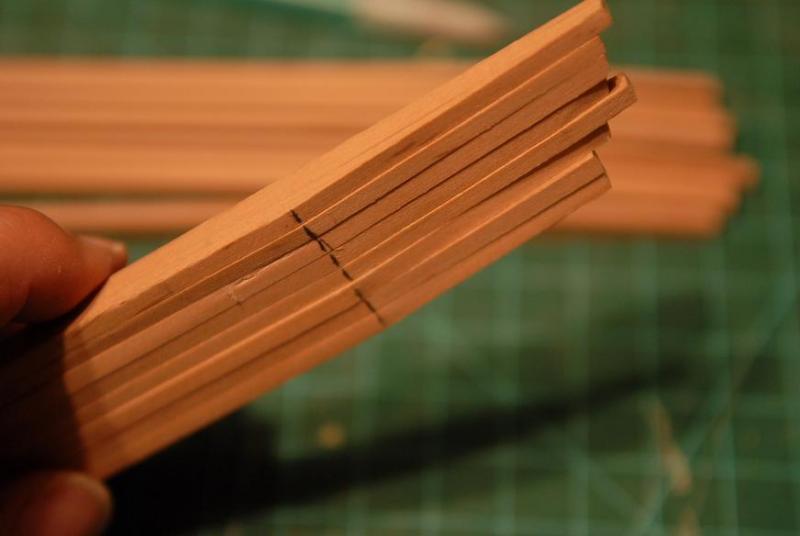
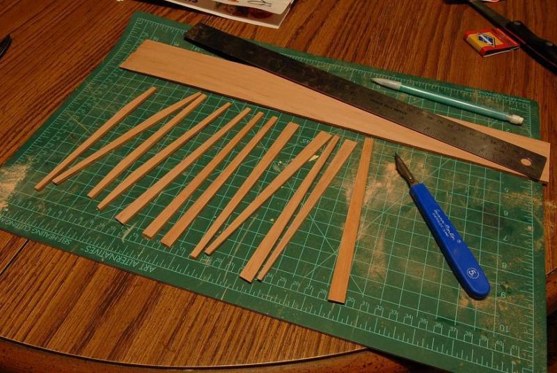
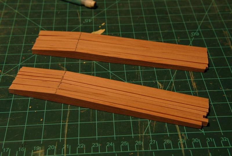
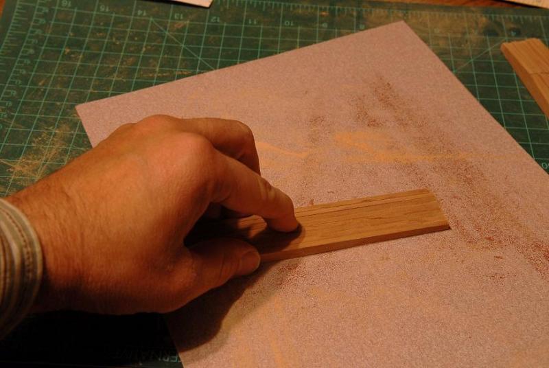
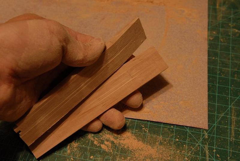
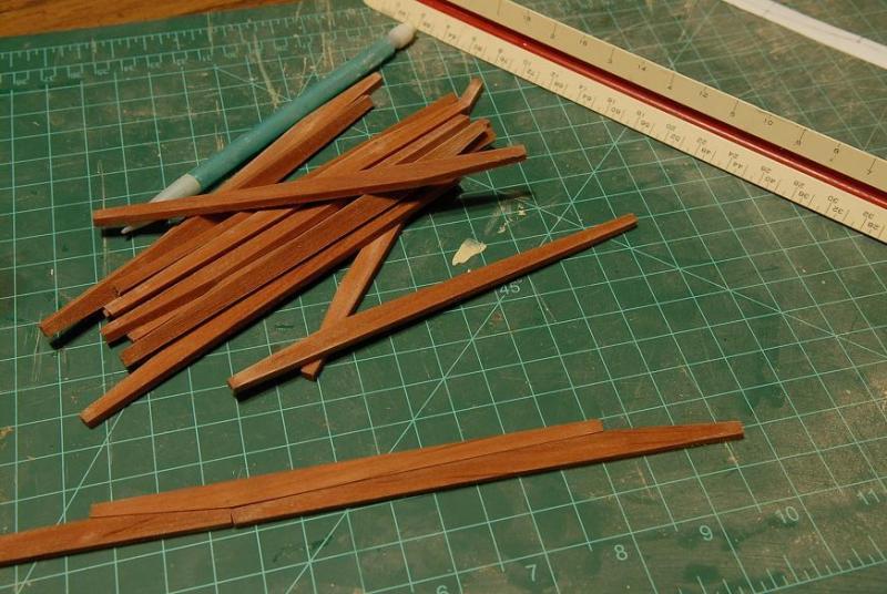
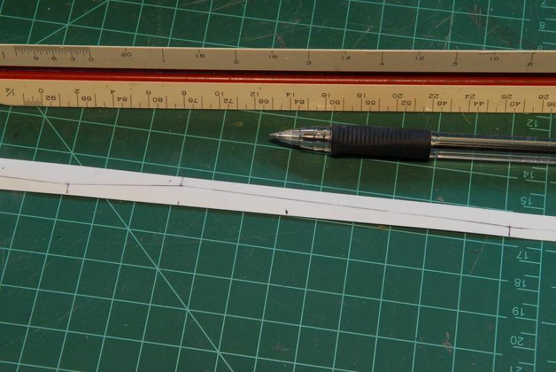
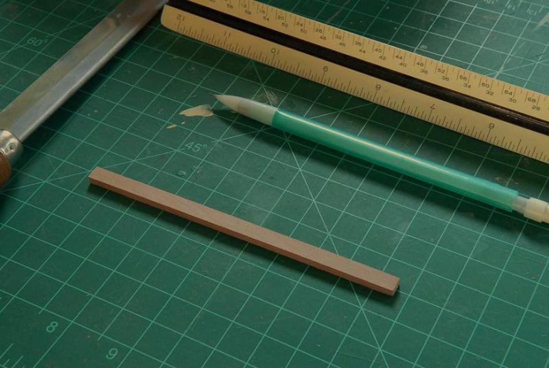
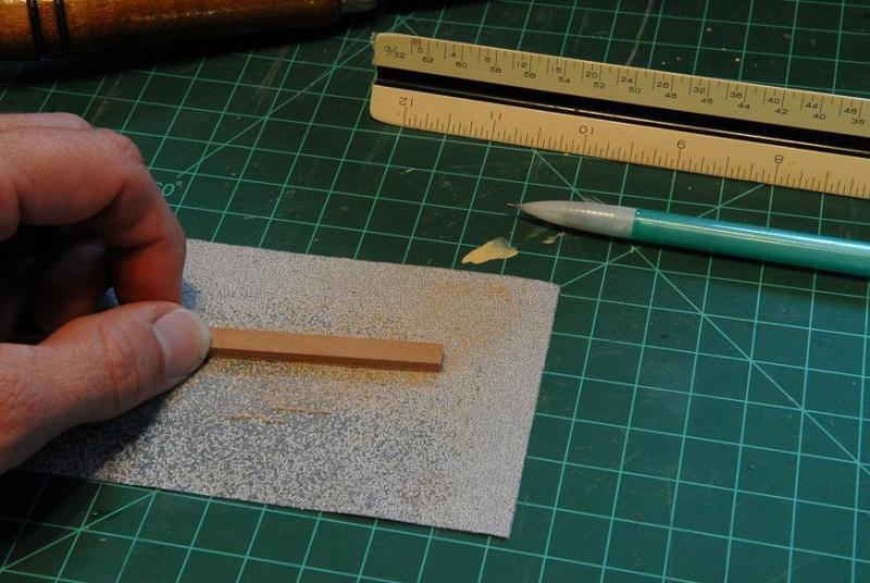
October 25, 2009 I've spent a lot of time trying to get the top wale strake on right. Following are some pictures of various clamping arrangements, of different parts of the first strake-- After this dried I was unhappy with some of the "lay" of the strake. I took the 1/8th" square "guide" piece off so I could see the run better, and I unglued and reglued the aft end-- I ended up ungluing and regluing the bow piece three times on the starboard side, and twice on the port side. I think the curve looks good now. In the middle-left of this photo you can also see a piece of a broken bow plank. I had actually over-bent it, and when it was dry I tried to bend it back a little too forcefully and it snapped-- Now, because I'm trying the top and butt arrangement for the bottom two strakes, I need wider wood than comes with the kit. So I'll have to order some and wait. I'll have to work on some other areas before continuing with the lower wale strakes. Maybe the deck clamps since now I will have the reference point of the top of the wale to help locate them. October 28, 2009 Instead of waiting, I have some sheets of 1/8th x 2 inch Pear to cut the wider wale planks from. I could order some 1/8th x 3/8th inch strips to make them from, it would go much quicker. The Pear takes a long time to cut with a knife. I think it took about an hour to cut these two pieces! But even if it takes me another week or so to get through these, it's faster and cheaper than ordering more wood. Supplies needed--my paper template, steel ruler, pencil, knife, sandpaper, sheet of wood. I also found some info in rereading Goodwin that puts me a little more at ease about my interpretation of the wale--straight strake at the top and top and butt strake below. That's the way the lesser wales (channel wale and the one below that) on the big ships were often built. November 1, 2009 I am continuing to cut out the wale planks with the knife. Here are twelve. I have only four more to cut. The second angle (as on the four planks to the left) is done with sandpaper-- November 7, 2009 I got a jeweller's saw, just in time to cut out the last wale plank! Here are the 16 wale pieces-- I spent a little time piecing them together and realized that the angles I have made vary too much to allow the top and butt wale strake to come together well. I cut and sanded the planks by eye, and most were cut from a "master" plank, but the variation between pieces is too much. I decided that I needed to do something to "standardize" the pieces. So I divided the pieces into two groups of eight, and glued them together-- This gives you an idea of the variation between planks-- After the wale pieces were glued together I sawed the extra length off-- Four planks in each of the two groups will only be partial length, so the short ones in these blocks are okay-- Then I sanded the angles to make them all more consistent-- Each end of the pieces should be equal and half of the total width. Gluing them together into blocks made this easy to correct-- Here are the "waleblocks" sanded. Some pieces are still a little "off" but I think the majority are much more uniform than before-- After the sanding I put the "waleblocks" in hot water and they easily fell apart-- Now I have my uniform wale planks-- Ron


-
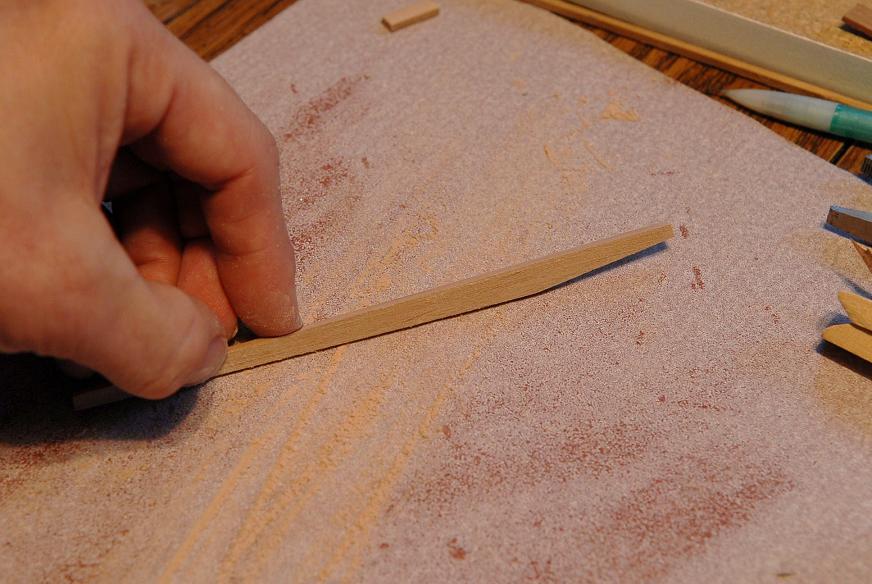
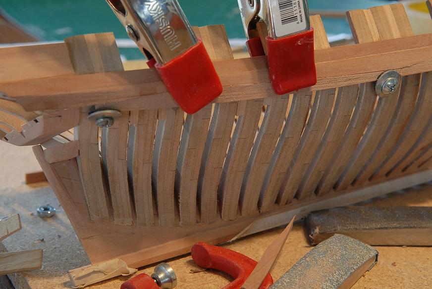
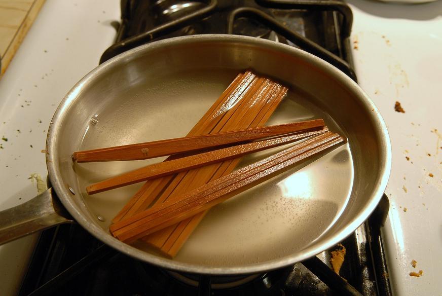
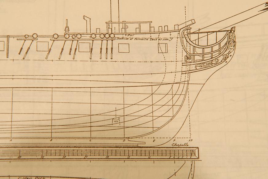
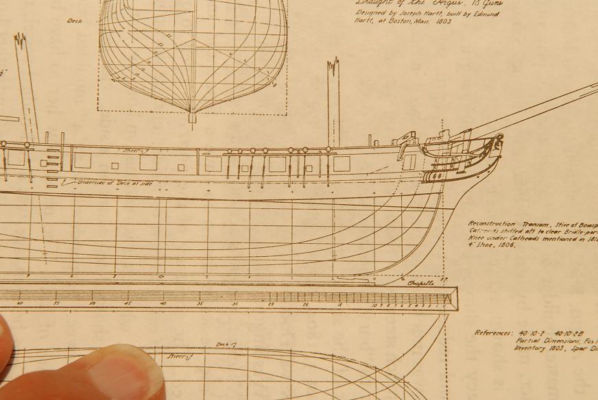
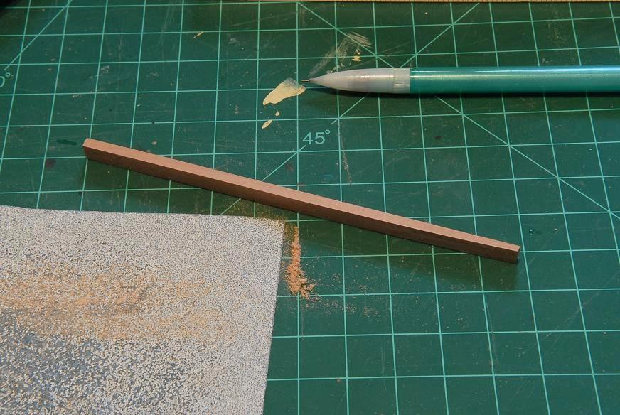
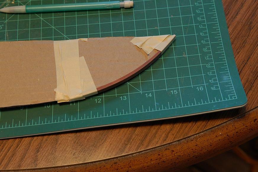
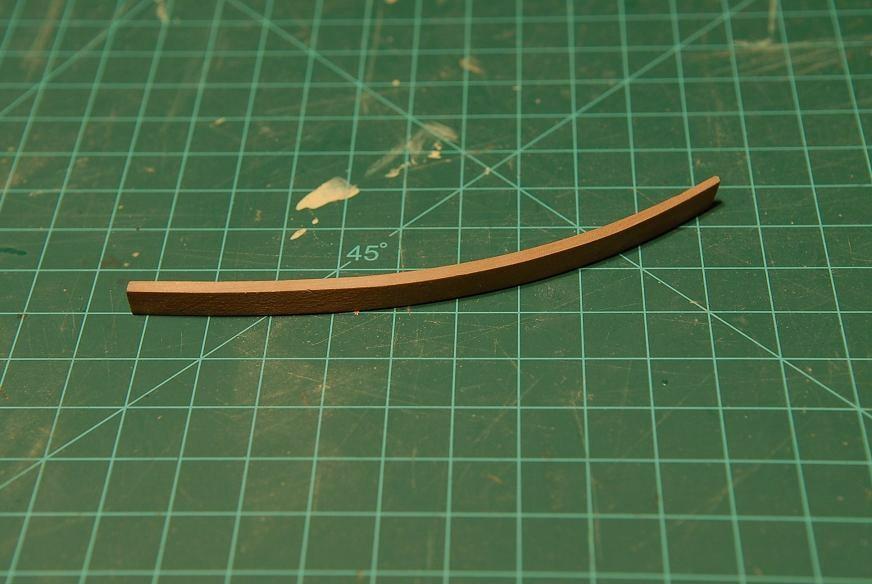
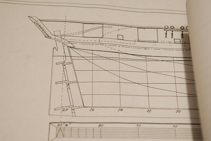
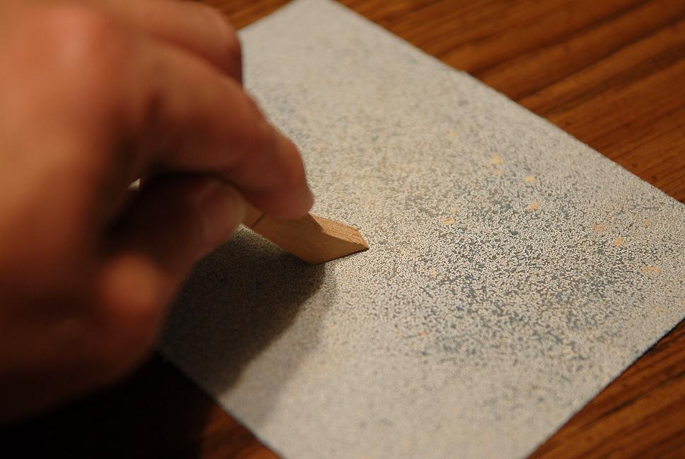
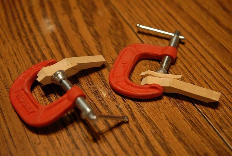
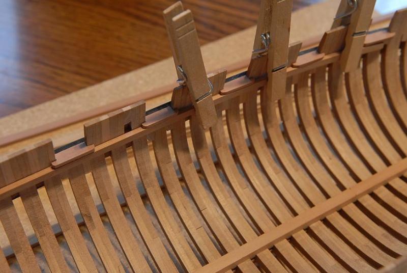
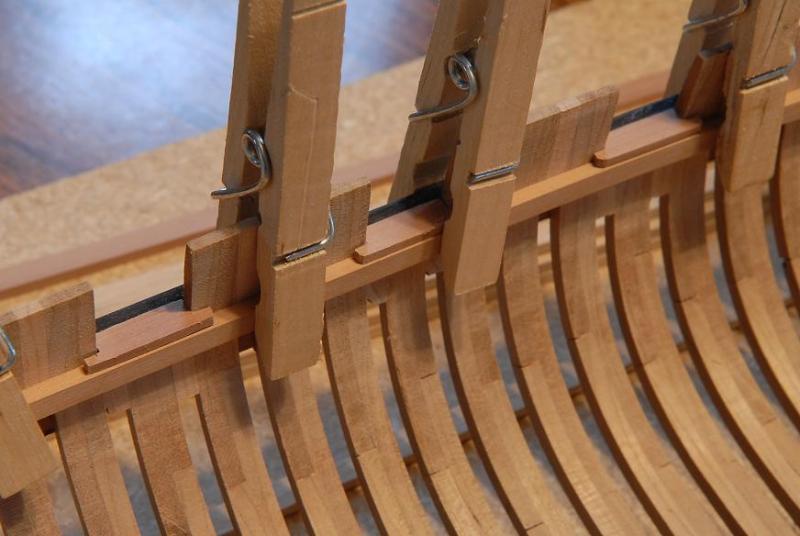
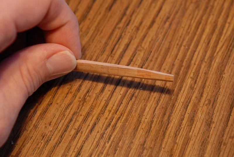
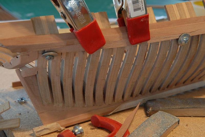
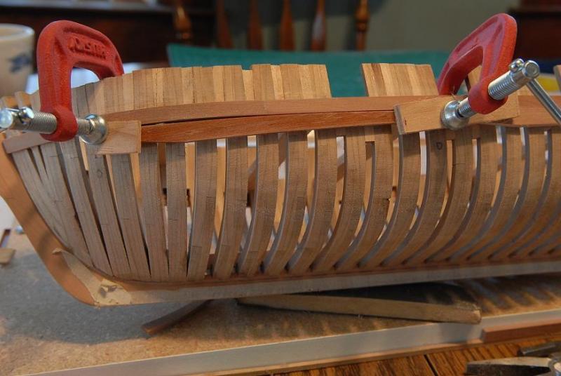
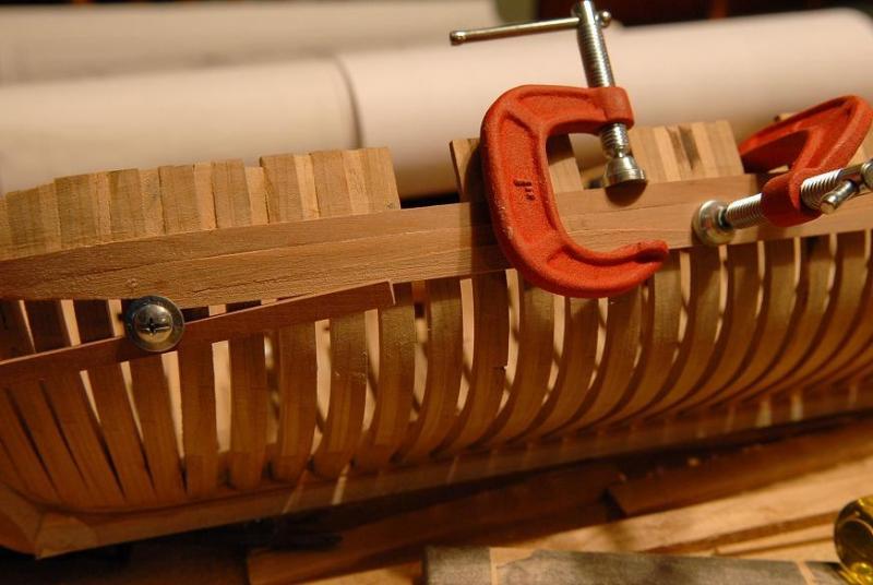
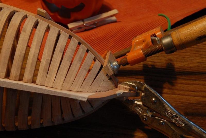
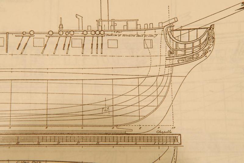
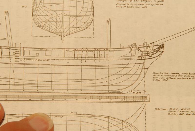
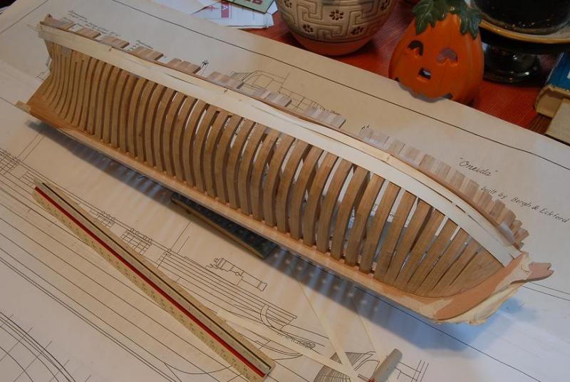
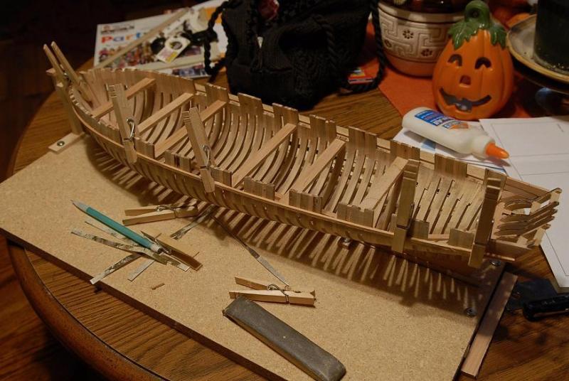
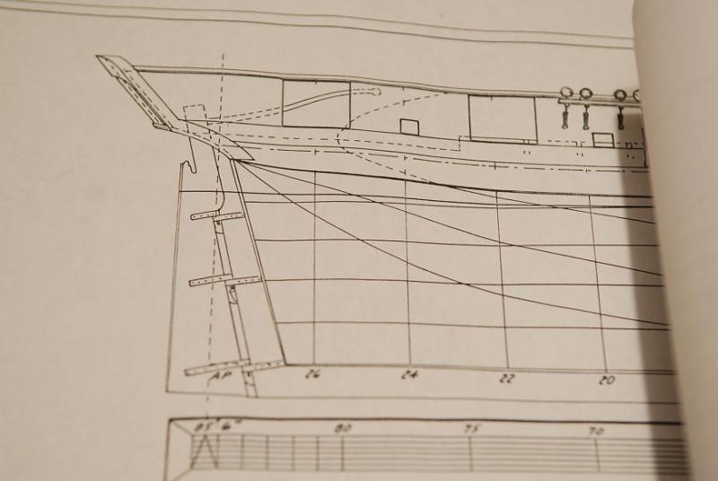
October 17, 2009 I have decided to put the wales on, to give some strength and stability to the hull before finishing the sanding. I'm really afraid of it springing apart on me if I don't bind it together a bit. First decision was whether to put the wales on in one piece, or to go fancier with multiple pieces. Then the question becomes, how are they joined? Butted together? Scarf joints? Anchor stock? I don't think it would be the latter in this case. I can't decide this yet. I will thin the wales at the bow, so they bend easier and I believe it's historically accurate. At least I can mark the location of the wale on the hull. I consulted the Chapelle plans (presumably traced or copied from the original Christian Bergh plans) and discovered that the wale was not shown the same width as the three supplies pieces would make. (The wale stock is 1/4 x 1/8 inch) In fact, on the Chapelle plans the total wale varies in width. The Lumberyard plans have simplified the wale for easier building, but I can see from comparing them that the original plans have nicer proportions. There will have to be some tapering of the wales if I want to match the Chapelle plans. The Chapelle plans also show a line dividing the wale. What is this? Does it mean the top wale strake is a 12" width and the lower one is larger, or two smaller ones? This is a mystery. [if only I knew then what I know now!] At the stern, the Lumberyard plans don't seem to account for the wales curving under the transom-- So I have a few things to puzzle over before I progress. The stern framing was a tricky construction, but things are not getting any easier!! Ocober, 17, 2009 I'm much more at ease about the flexing of the hull during the next steps after gluing in some temporary beams [A suggestion from "Jim Lad-John"]-- The wale strakes curve around the hull, which would shorten the vertical dimension in elevation on the plans. This is the approximate location of the lowest wale strake-- I marked the top of the wale, and glued a strip of cherry (a piece of the stock to be used for the deck ledge beams) to test he "lay" and act as a guide for the wale strake-- I think I will make the top wale strake the full 1/4 inch width, and the two lower wale strakes will be narrower and tapered fore and aft. . Maybe the lower strakes should also diminish to meet the hull planking. [i wish I had done this] October 18, 2009 The only information I've been able to find that supports the way the tapered wale is drawn for Oneida is some writing in "The Built-up Ship Model" by Charles G. Davis. He writes about the wale following the "5-4-3" rule where the widest point is 5/5ths the total width, the bow 4/5ths and the stern 3/5ths. That looks pretty close to what is shown on the Chapelle plans, and the author's model that is illustrated in the book follows that rule. I've also looked at the other ship plans in HASN and while most seem to show wales of a constant width, there are some in addition to Oneida where the wale varies in width. However, Davis and Goodwin also describe the wales in groups of two strakes to accomodate the top and butt or anchor stock patterns. Usually then there are four strakes that make up the main wale. My wale is to be three strakes. Possibly the top strake is a full 12" width, butt joined, and maybe the lower two strakes are either top and butt or anchor stock. That might explain the drawing of the wale on the plan as a twelve inch top strake and another variable width (from about 16" at the stern to almost 24" at the widest point to 18" at the bow) strake below it. Here's the picture again so you don't have to scroll back-- Here is the Raleigh, which shows a tapered wale, though itis an earlier ship--1776-- Here is the Argus, 1803 which is close to Oneida. It shows a wale of constant width, but like the Oneida plan it does show a line for the top strake of the wale, but doesn't indicate the wale strakes below-- I'm proceeding with the idea that on Oneida the top wale strake is a constant 12 inches, butted together [maybe I should have hook scarfed them, but this idea was just a little too overwhelming for me at the time]; and the lower strakes are top and butt joined, making an overall strake of varying width. Who knows if this could be true, or if it's just a faulty extrapolation of my limited knowledge! [i say that with my current knowledge it's possible that it was built that way, but the thing I missed was that the top strake was probably not as thick as the lower ones] First I cut some heavy paper (the back side of an old photograph) to make two wale strakes. The top one is divided into 24' planks, the bottom one is a continuous piece that tapers at the bow and stern-- Then I took the bottom one off and drew the top and butt pattern on it-- And taped it back onto the hull to check it out-- I'll ponder over this some more before I actually start cutting wood. October 20, 2009 That pumpkin sneaks up on me. I will have to make sure it doesn't take a bite out of the ship. And before anybody asks, the purse is my daughter's! I glued the port side wale guide piece on, taking care to make sure it was as symmetrical as possible to the starboard side-- Then I went to work on the upper strake of the wale. First I cut a 24 foot length-- And sanded the forward end to decrease the thickness to just a bit over the regular planking thickness (Which is 1/16th inch--3 inches in scale)-- Then I heated the piece up. I took it out after about five minutes, before thewater even started to boil. I was surprised at how easily it bent-- I taped it to the inverse of the form I had made to help with the hull framing. I'm glad I kept this cardboard piece. This probably isn't exactly the shape at the wale, but it should get me close-- When I untaped it there was a little springback, so I gently overbent the piece by hand, cold, and now it's pretty close the final shape. I also needed to twist it some, which I also did cold-- Here it is dry fit on the hull-- When I clamp the piece down the gaps will go away-- Speaking of clamps, my clothes pins aren't going to cut it for this work. They aren't long enough. I'll either have to buy some longer, stronger squeeze clamps or get some rubber bands and rig something up. For once I'm not going to rush and glue this up tonight with the inadequate stuff I've got on hand. Maybe I'll even cut out all the first strake pieces for both sides first, and bend the other bow piece. I think the bow piece may be the only one that needs to be pre-bent. The bending is pretty slight for the other pieces. Ron


-
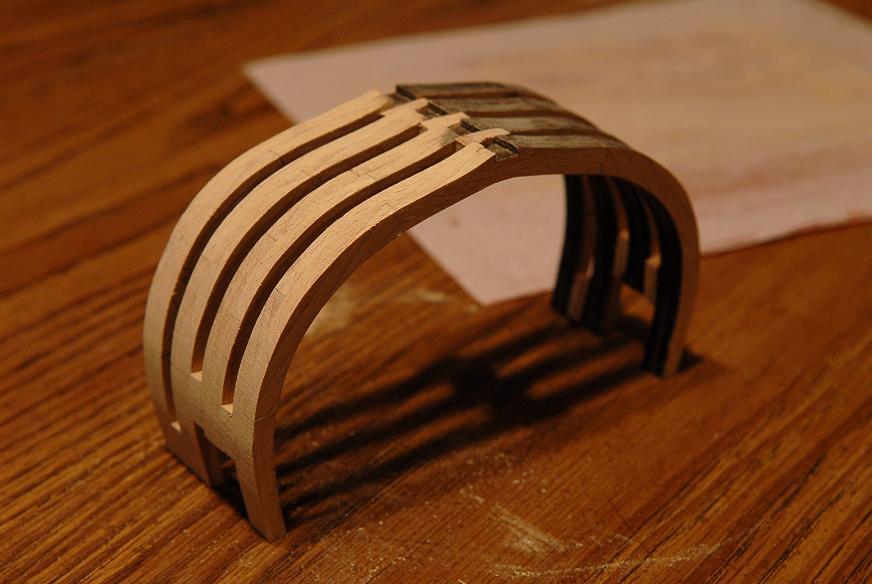
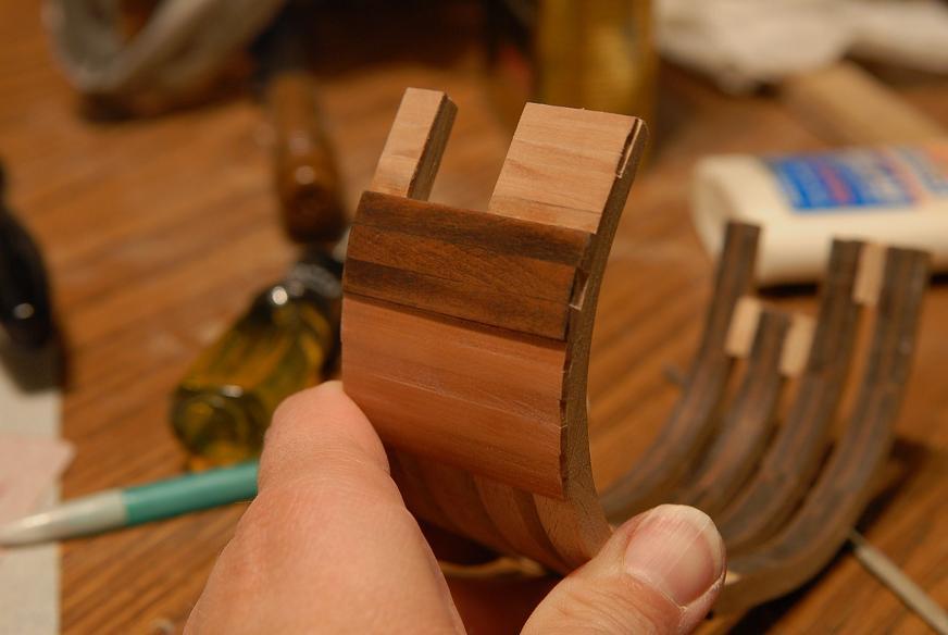
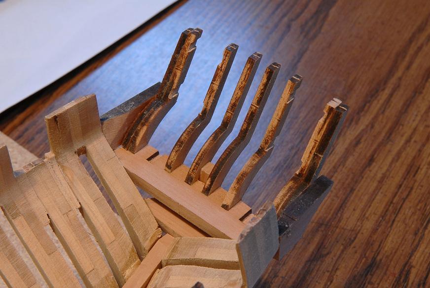
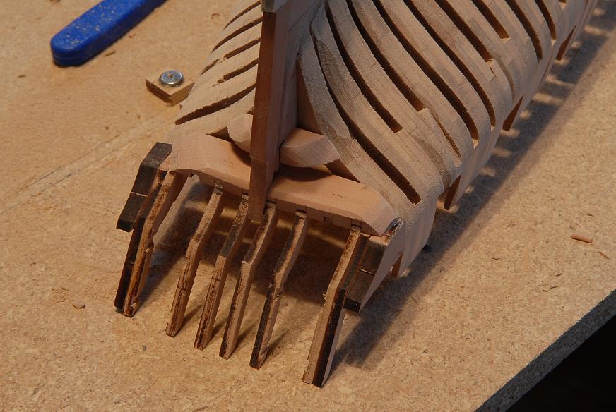
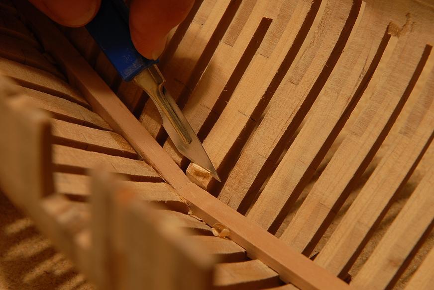
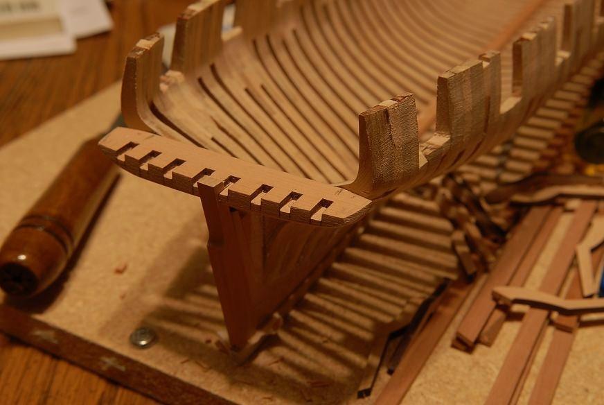
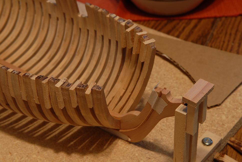
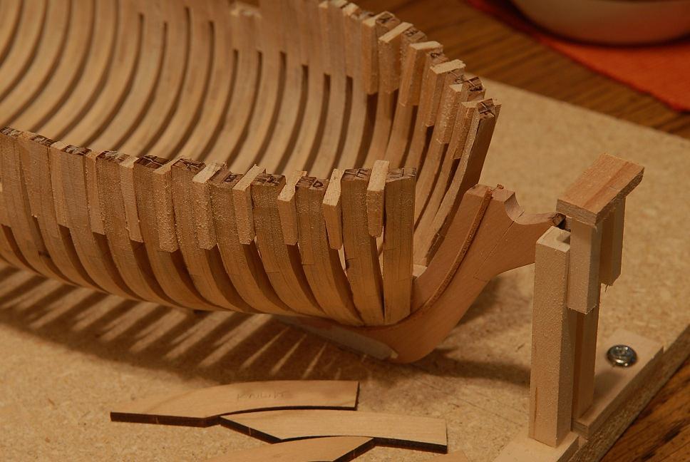
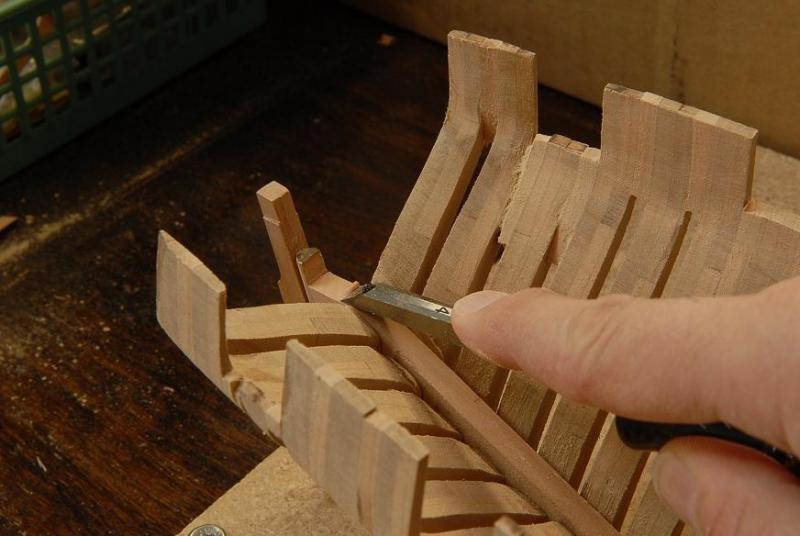
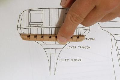
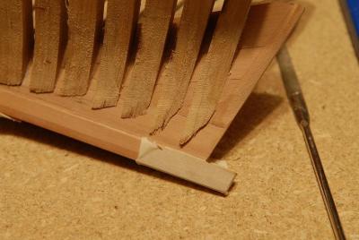
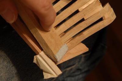
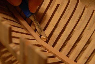
October 11, 2009 In between sanding sessions on the inside and outside fairing, I am working on the stern framing. The counter frames need some slots cut into them for gunport framing-- I cut a template to make sure I get the angle of the counter timbers right-- The deadwood needs to be cut down to receive the lower transom piece-- After more filing and dry fitting, the deadwood is ready for the transom pieces-- I glued the upper transom with the counter timbers on, but not so securely that I can't easily remove it if I need to perform more drastic corrective actions-- John wasn't kidding when he said that the stern was the most complicated part of the hull. I think my stern is not entirely correct. I think my half frames didn't come out exactly as they should have. But I will continue and hope that it will end up okay. More corrective actions may have to occur, but I won't know for sure until I get further along. October 11, 2009 Forging ahead, I glued the outside counter timbers on. These should have about a 2mm gap from the next-to-last pair, but because of my stern being narrower than it should be (even after my drastic frame surgery) I glued them right up against the previous pair. If this turns out badly now, it's going to mean scrapping a lot of work-- Then I glued two filler blocks on-- This is how the starboard filler block looks before shaping-- I have the port filler block about 80 percent sanded to shape-- It's interesting to see the shape of the stern start to become defined. I just hope I haven't messed it up too badly. I'm thinking that I might have to do some modification to move the two transom gunports a little closer together. That's partly why I haven't framed them out completely. October 13, 2009 I'm spending time shaping that upper transom piece. I'm trying to puzzle out how the hull planking, and transom planking need to meet at this point, and how that affects the shaping of the transom piece-- Looking at the plan, it appears that the lower curve of the transom (which the sternpost and rudder pass through) is straight from side to side. Not like the upper part of the stern which has a shallow curve from side to side. However, the way the kit is constructed, the lower curve is curved from side to side, same as the upper part. So, I think I need to sand this lower curve straight across-- I've removed the sternpost to make these surfaces easier to get at-- And I sand the transom piece and counter timbers straight across on the lowercurve-- In looking at the online instructions--which I should do more often--and Elia's gallery photos--which I do quite often--I realized where some "extra"pieces I had need to go. I really didn't know where these four pieces belonged until just now!-- They fill in the bulwarks from the last frame to the transom. I need to adjust them for my narrower stern-- All glued up and ready for more carving and sanding-- I have finished sanding the side filler pieces and added the port framing-- I think the next step is to do more fairing of the hull and then it's on to the wales! But I am wondering if it would be a good idea to finish fairing the wale area, and glue those on before really sanding the rest of the hull. The hull is not far off being fair now, and I am experiencing more splits in the willow spacers. As I sand the frames a little thinner, and handle the hull more, there is more flexing going on, and I'm thinking the wales would add a good deal of stability and strength. You'll have to excuse my smiling pumpking for a couple more weeks until Halloween is over. Ron


-
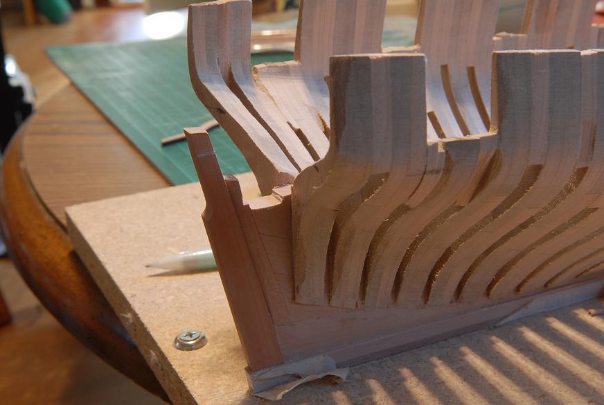
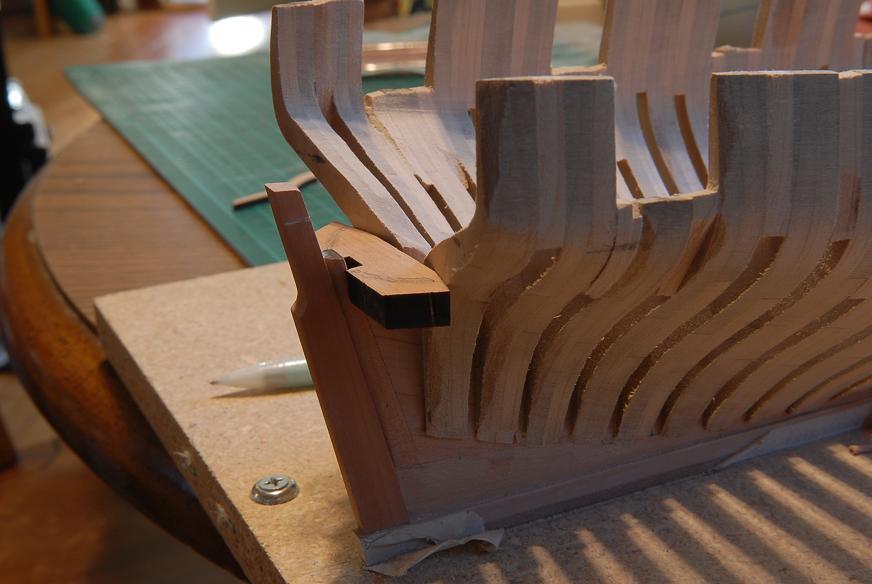
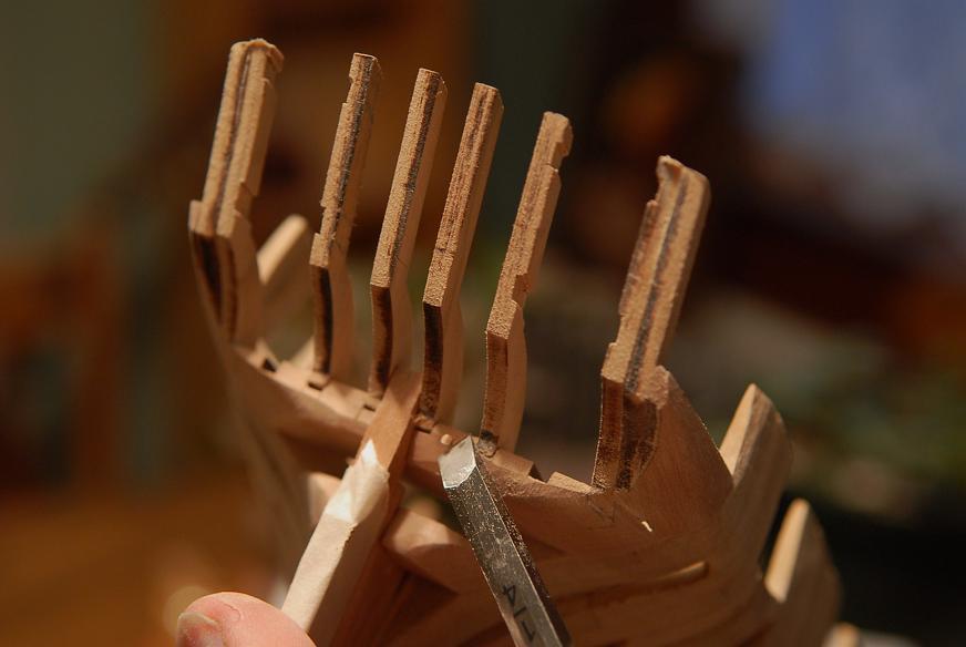
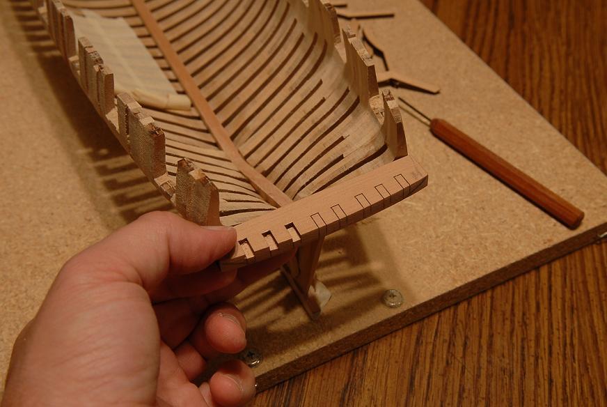
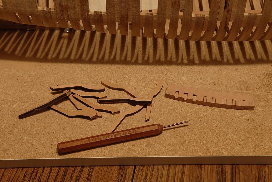
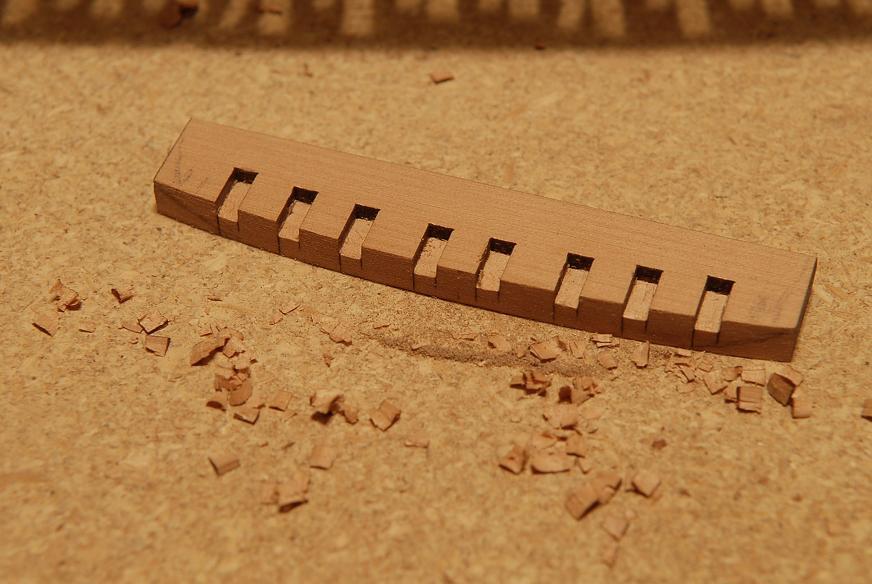
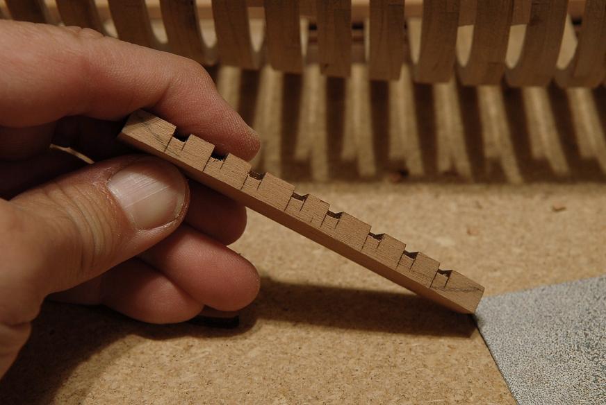
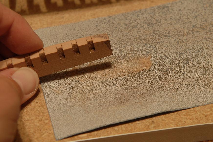
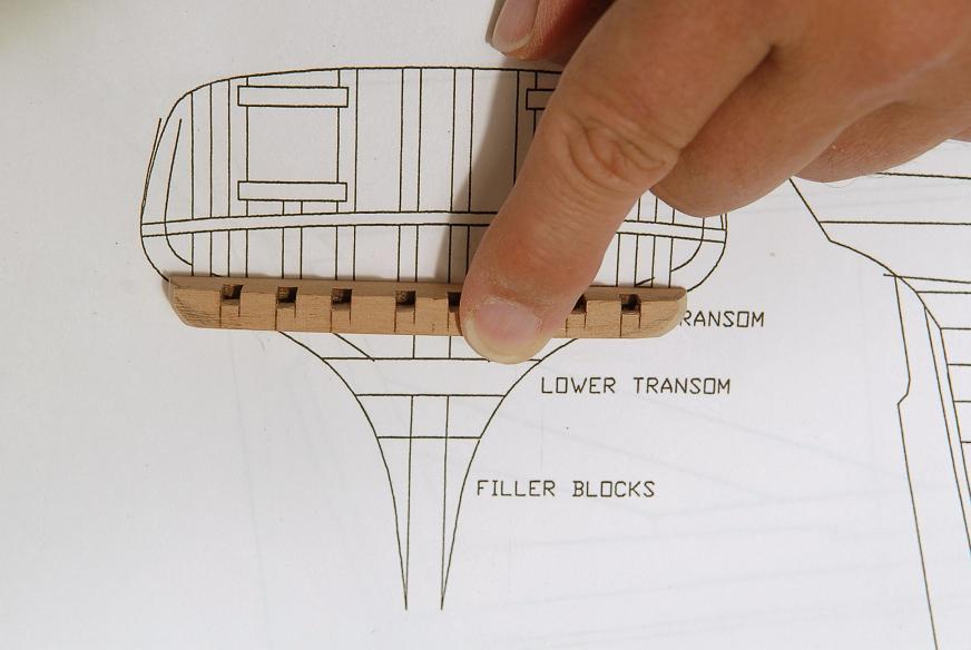
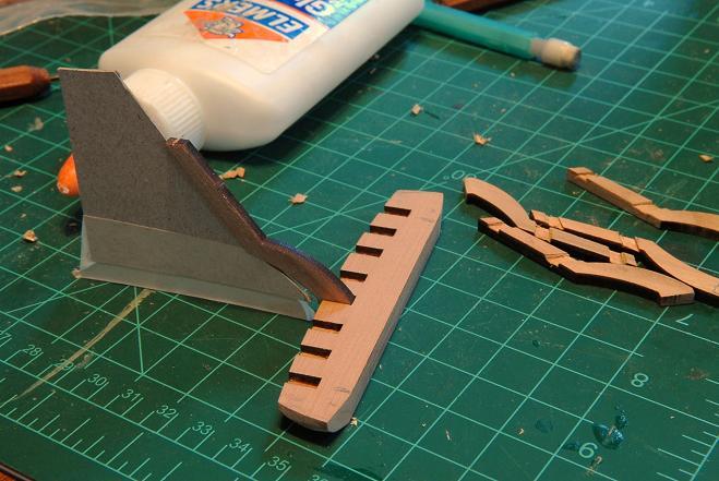
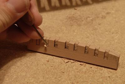
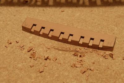
October 7, 2009 As I labor along sanding the frames, I can take a break to do some other things, such as work on the transom pieces. Here is the upper transom, held approximately in place on the stern-- On the left are the counter timbers that will fit in the notches in the transom piece-- The location for the counter timbers are laser cut into the transom. Very small chisels are needed to carve out a notch to receive the counter timbers. This step would be much harder if the boundary lines weren't already laser cut-- The notches are cut-- I've decided to do some preliminary shaping of the transom piece, because I think the counter timbers are going to be very fragile, and if I can get a jump on the shaping before gluing them in, it might help avoid breakage-- There is much more shaping I could do, but I'll leave it for now--don't want to go to far, as it's easier to take wood off than to put it back on-- Another break from sanding the inner side of the frames is cleaning up the frames at the bearding line. It's pretty messy-- I sand the frames which are currently extending below the bearding line-- Trim them when they are just about sanded off-- And last I have tacked the sternpost on temporarily to help with locating the transom pieces. I'm not sure at this point whether I will permanently attach it before or after the planking-- October 9, 2009 I'm still working on the inner frames. Some need more drastic action than just the sandpaper-- And more work on the upper transom piece. Here I am cutting a slot for the sternpost-- Here are two shots, one without, and one with (dry fit only) the upper transom-- I've realized that the last stern frames taper in a little more than they should. The outer edge of the transom piece and the last frame should meet at about the same point. Sigh. I'm not sure I'm going to try to fix this. I might just go with it and accept a slightly narrower stern. I will think about it. The fix would probably be taking the last two frames off and making a very slim wedge to put between the frame and deadwood to change the angle. I have to consider whether the work to fix it will be worth it. Even as I type this I know the answer to that. [There are a lot of reasons this could have happened, including--the tapering of the keel and deadwood, innaccurate sanding, working by eye instead of measuring constantly. All could have been prevented using a framing jig.] October 9, 2009 I decided to take the last frames out. First I cut through the spacer wood-- I applied isopropyl alcohol to keel joints, and then cut through the softened glue-- The frames came off okay, but left some bits behind-- I took a small sheet of cherry to make wedges from-- And sanded it at an angle-- Then I cut it into four pieces-- And glued them to the frames-- Sanded the ends some more, after test fitting on the hull-- And glued the frames back on-- The next pictures compare the stern before the fix-- And after-- [it doesn't look like there's much difference here. These photos could have been better. It's a few millimeters on each side, which is significant, as my stern even with this adjustment ended up a little narrower than it should have.] The second to last frame sticks out, but that will be taken care of with more sanding-- The fit down by the bearding line is not as good as before, but the overall shape and allignment at the top is better. Ron


-
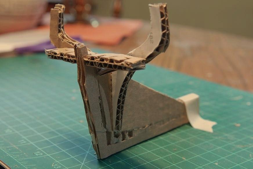
October 2, 2009 I had it in my head that the first few stern half frames were perpendicular, and not canted. When I went to the plans to make a template for the frame placement on the deadwood, I discovered that all the stern half frames are canted-- It's not a lot, but the gap at the keel is less than at the top of the frame-- Before I go back to the model, I'll make a template to guide me in spacing the frames-- I taped it onto the keel, aligning the rabbet line, and traced the curve and marked the frame locations-- And, flipping the template over, did the same for the other side-- Now I needed to fix the non-canted last frame. I considered leaving it, and adjusting the spacing of the rest of the frames, but I decided to do the right thing. I cut the frames loose at the keel, leaving them attached at the top-- I sanded down one of my spacers to match the narrower spacing of the keel end of the canted frames (The upper spacing remains the same as before)-- I scored the piece and broke it in half-- To apply glue to the keel attachment, I used another scrap of paper and applied glue to both sides. Then I held the frame away just a bit, and slid the paper into the joint to get the glue in there. I put my spacer in and pushed the frame tight-- Did the same for the opposite frame-- And rigged some rubber bands to hold the fix while it dries-- The completely right thing would have been to cut the frame pieces off completely and resand the keel ends to a very slight angle, but the difference was so slight on this first frame that I elected not to go that far. The next frames will have that edge sanded to the right angle. October 3, 2009 [i posted that I was having a lot of trouble visualizing how the stern and transom are supposed to go together. I knew from other builds and pictures how it was supposed to end up looking, I just could build it in my mind. I got this reply from "Jim Lad"] The stern is the most complex piece of framing in the entire hull Ron. If you're having trouble visuallising it, you could always do a rough mock-up in card to help your mind to 'click' onto what's happening there. John. John, thanks, great idea to do a mock-up. It's not complete or pretty, but it gives me some of the relationships between pieces that I was looking for, especially concerning the rabbet/bearding line, which I have to fix pretty soon-- October 4, 2009 Here's my fix for the stern deadwood. [i didn't taper the upper pieces before I glued them to the tapered keel. In addition to that, because the kit is not designed to be planked, I anticipated a problem with how the planking was going to lay in this area if I followed the framing plans exactly.] I determined that the simplest, best way of fixing the problem was to move the bearding line up a little. This might be changing the hull lines slightly, but then again maybe not, because the Lumberyard frames in the stern are based on not planking, and not tapering the keel. So I think I'm on reasonably solid ground with my solution. I also know the attachment of the frames is not per actual ship building practice, but simplified for the model. Anyway, I sanded the deadwood to put the vertical rabbet and the modified bearding line on-- I redrew the pencil line with my frame spacing marks. My technique for sanding the angle at the keel end of the frames was pretty primitive. Just sand it by eye and dry fit. Then sand some more-- Here's a photo of two frames held together. The sideways angle of the sanded end is right, but the problem here is that the one frame is going to be "wider" than the other. I need to modify the vertical angle to get them to match-- Here I am holding the frames on to the hull to dry check the fit-- Here I've glued a frame set on, but before the glue sets I check to make sure the width roughly matches. Half the frame will get sanded away in the fairing process, so I only need to be within about 1/16th inch-- Another set glued up-- This is a frame that doesn't fit right. The horizontal angle is too much, making the outer gap too big; and the vertical angle is off, making the frame extend too "wide''-- This is the same frame with the angles corrected-- This shows the frame from the previous picture, and it's mate not sanded yet-- And now they match-- In this picture you can see a sliver of light between the spacer and the frame, indicating I tapered the angle on the spacer too much. (Tapering the spacer is only necessary on the shorter gunport frames) I filled the gap with glue-- And now I'm done with the stern frames! Next job will be the transom pieces. Whoops, slow down. Next job will be fairing the inside of the stern frames. Ron


-
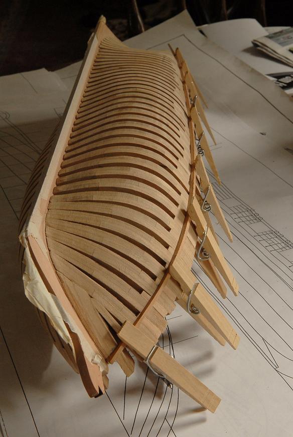
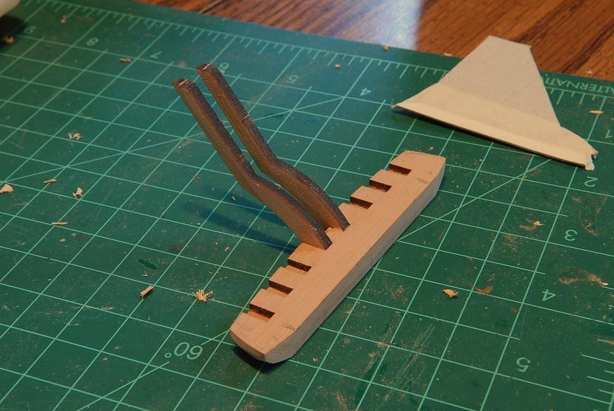
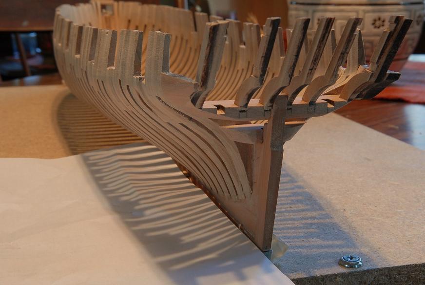
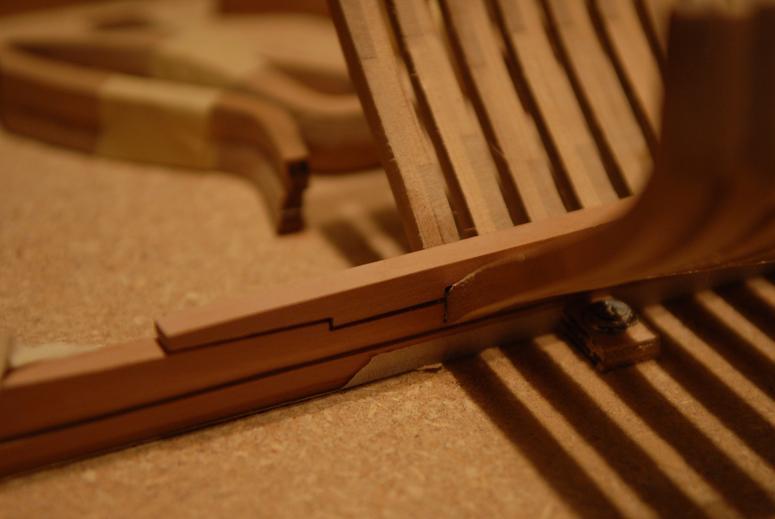
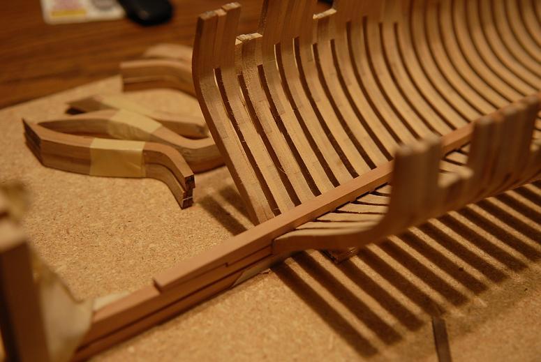
October 1, 2009 I have sanded the bow framing enough for now. Following is the installation of a stern half frame set. First I needed to make some spacers from the supply of willow. I cut short lengths that would be easy to sand-- Using 80 grit sandpaper, I sanded and frequently checked the width-- When I sanded all the pieces to the right thickness, I cut them into smaller pieces that would be used to space the frames correctly-- Then I took the frames themselves-- And sanded the lower face flat-- Then I glued the willow spacers to the last frame in the hull-- Applied glue to the frame-- And to the spacer-- And placed the frames on the hull-- I checked the allignment, and when all seemed good I used masking tape to fix the frames into place until they set-- The next frame was an incorrect one. It was not shortened for the gunport-- I laid the frame set on the plans and marked the location of the gunport sill-- Then I sawed the extra part off of the frame-- Ron


-
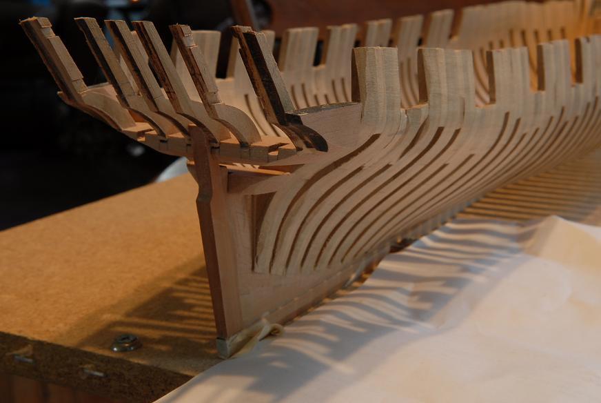
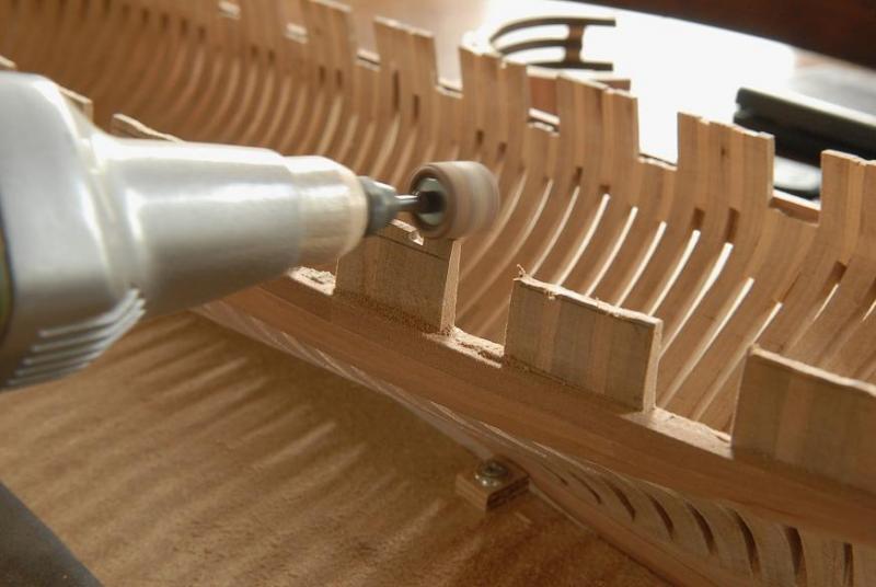
September 26, 2009 I've glued the keelson on, and then the stern deadwood-- I had already glued up the four pieces into one unit. So this was a simple job here. The lowest piece--which was glued to the keel long ago--has been shaped for the rabbet/bearding line. The upper deadwood now has to be shaped also. I think I will cut a template out for the bearding line. I also need to make some cardboard templates to help me get the rest of the frames on right-- Here's a photo taken in the window light, this is a truer color rendition-- The first set of bow cant frames are sitting there. I'm still puzzling over how best to go about this phase. September 27, 2009 The Lumberyard directions are very simple on the cant frames. (I won't explain it all, you can check out the Oneida directions on their web site.) I followed the directions but added a couple things to hopefully improve my chances of getting it right. [What I didn't do, and should have, was make a reliable jig--you'll see why a few weeks later in the build!] First I glued a piece of 1/16th square strip wood into the rabbet to provide something for the frames to "stop" against [removed after the bow framing was done]-- Then I glued the first frames, using the willow "spacers" to make the shape-- I made a template to guide me. This is highly inexact, but I think it will at least let me know if I start going way off. The frames are cut very "full", and there will be a lot of sanding to get to the final shape-- All the bow cant frames are glued! At the lower edge of the next picture you can see the bollard, knighthead and hawse timbers, which will be the next pieces added-- The hawse timber looks a lot like a No.11 X-acto blade!-- Here are the last bow timbers in place, ready to be carved and sanded to shape-- The port side is roughly to shape now-- More sanding to follow. I'll get the bow pretty much done, and then turn to the stern half frames. September 29, 2009 After the accomplishment of getting the bow timbers installed, I'm back to slow sanding. I did use the "dremel" to take down some of the excess wood on the inside of the hull. You can see some uneveness in those starboard cant frames. But it'll be easier to even that out than it would have been to take all the excess wood off by hand sanding, it's so hard to get in there with the sanding sled. Even as I sand, the stern half and cant frames are out, reminding me to start mentally gearing up for that work-- The general mode of work on this kit seems to be "get the oversize pieces together roughly, then sand it into shape." It's a very forgiving method, and doesn't require the utmost precision. I think it's actually pretty good for a novice builder, because I don't have the frustration of trying to make everything exact, but I can learn as I see it go together, and get some idea of what I would have to do to make it in a more precise way--next time perhaps! And in the end, it seems to be coming out okay, so far. Shaping the hawse timbers was trial and error. Sand the angles, test fit the piece, adjust, test fit, adjust, etc. However, only the angle that they fit together had to be right. The rest got sanded off after gluing in-- On the starboard side (left side of the photo) you can see a small hole on at the bottom of the hawse timber where I didn't quite get it right. But that side will be planked over. The port side which is better will be unplanked. (At least thats the current plan!)-- I could start on the stern frames, but this week at work is turning out to be kind of mentally draining, so I will probably wait till the weekend for the framing work. For now I'll just keep sanding the inside of the bow. Ron


-
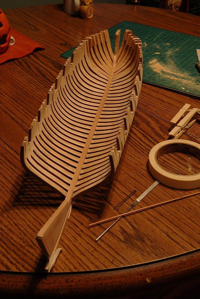
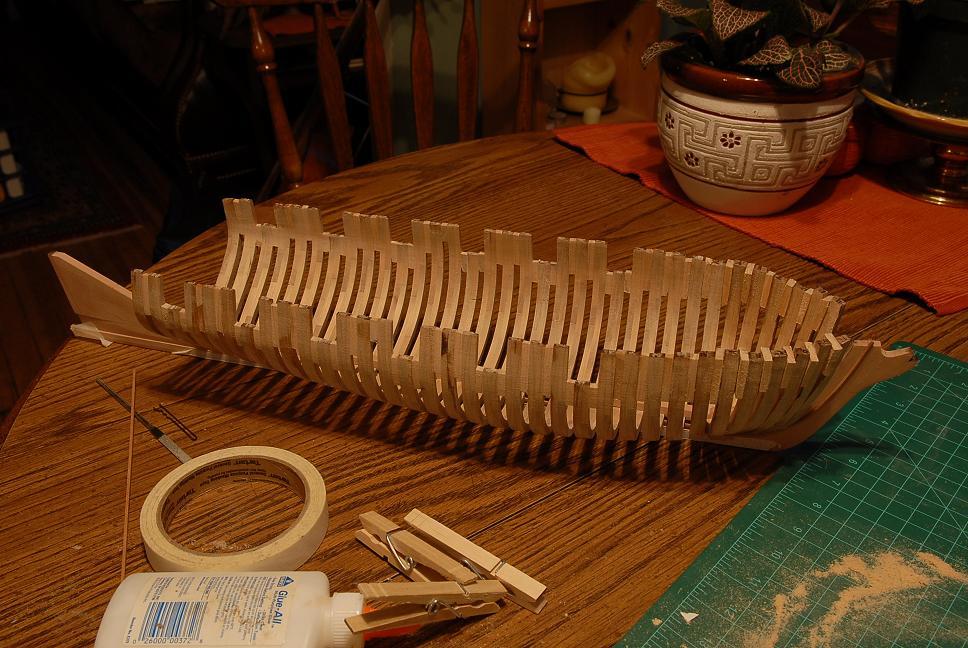
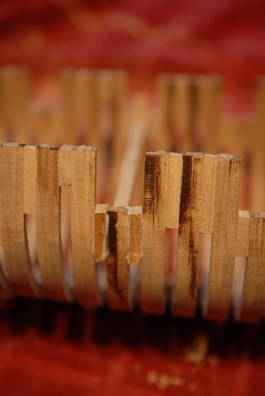
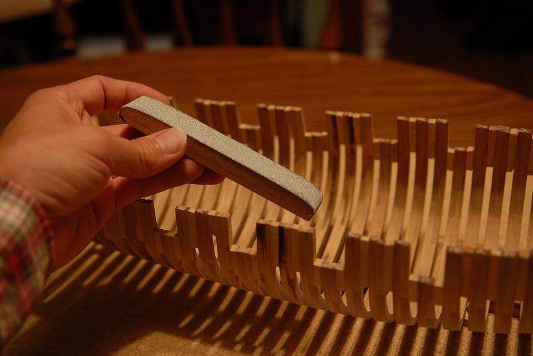
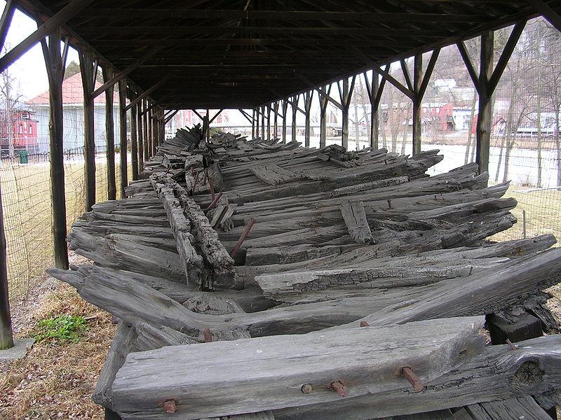
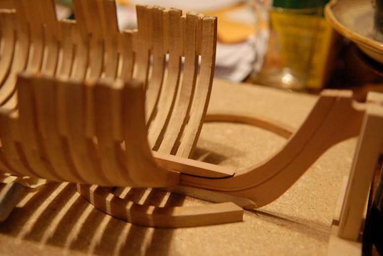
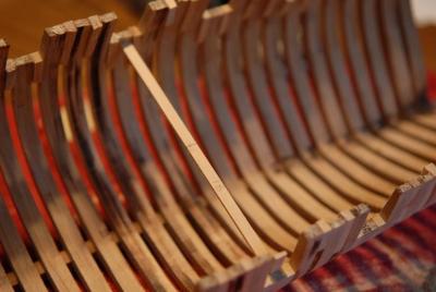
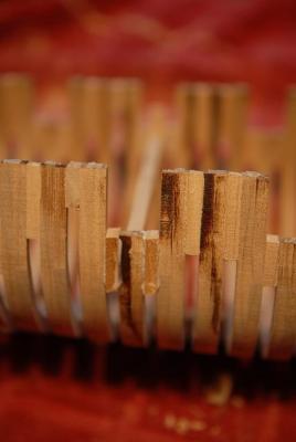
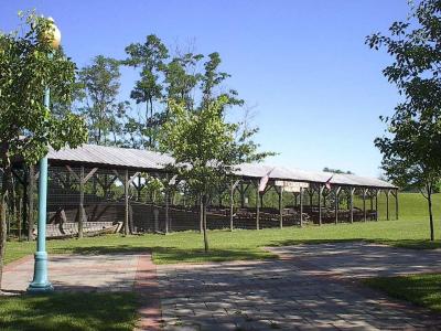
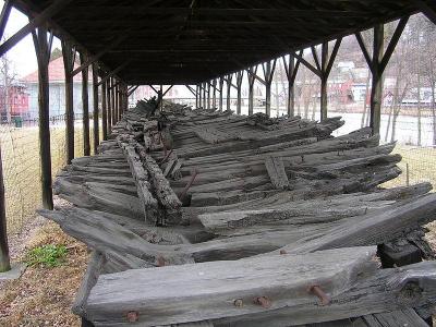
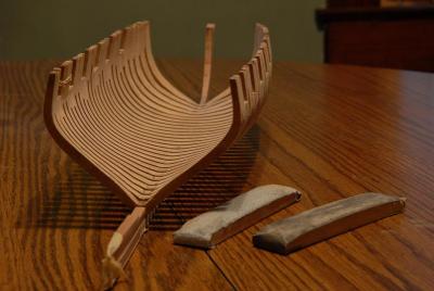
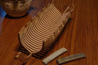
September 17, 2009 After sanding a while, I have one frame that I need to do some surgery on, to bring it out more flush with the rest. You can't really tell--these pictures aren't very good, but it's the shorter gunport frame near the center of this picture-- I sawed through the frame spacers-- Filed the sides of the frames smooth again-- And glued some new spacers in, with a piece of wood across the beam to push the frame out flush with the outside of the hull-- Once this dries, sanding can continue. September 18, 2009 I am learning a lot, and having fun. The learning and the fun don't always coincide. For instance, I learned a lot when I tried to solder the carronade, but it was not fun. When gluing the frames I learned about that, and it was fun! However, the sanding and fairing of the inside of the hull is the worst "chore" I have encountered so far. (Note: I have not had the pleasure of tying ratlines to date) The outside is relatively easy, but the inside is difficult. I tried using the rotary tool in a number of ways, but it was not really much use in the end. I could never really get the right angle, or sufficient control, except in a couple spots--even using a flexible shaft attachment. I tried a drum, a small disc, and a flapwheel. I have made a sanding sled, which is working so far, though I think I will have to make another, curved transversely as well as longitudinally. Not sure how I'm going to get sandpaper to bend both ways at once!-- September 23, 2009 Last weekend I visited Whitehall, New York, near the lower end of Lake Champlain, where they built some early US warships. There's a nice little museum that had more models than I expected. 3 or 4 of the gunboat Philadelphia . And outside under a very modest shed, the remains of the 1814 USS Ticonderoga. At first it looks like a huge pile of firewood, but a little study reveals the keel, lower timbers and some planking. (You can't get all that from this picture, but you can see a floor timber from compass oak near the front.) Actually very impressive. I didn't have my camera with me, these pictures are gathered from the internet-- On my model sanding continues. During my move I threw out a lot of packing foam and now I don't have any to make a better sled. I've rounded my wooden one a little more, and affixed a new sheet of sandpaper. This one's just about worn out now, too-- September 24, 2009 Just to give me a little break, I'm starting to work on the keelson also. It will have to go on before the half and cant frames-- The notches for the frames need to be filed deeper, so that the keelson will fit better-- September 25, 2009 The keelson is just about ready to go. But more sanding first. I think I'm done (for now) with the 80 grit. The first four frames need more shaping, but I don't want to do more until I get the cant frames on. I have made a second sanding sled and I'm using 220 grit on that one. It's starting to smooth the wood out, I can begin to see the wood grain as the striations from the coarser sanding disappear-- The edges of some of the frames look a little fuzzy in the next picture, but it's sanding dust, not wood fuzz. Should have dusted her off for the pictures!-- The rubber bands you see on the port side of some aft frames are to hold a repair. The wood used for spacing the upper parts of the frames is weak and tends to split apart (if I remember right it's willow [yes, it is willow]). I have had to make 3 or 4 of these repairs. The masking tape on parts of the keel are just to protect the wood from getting too banged up-- Ron


-
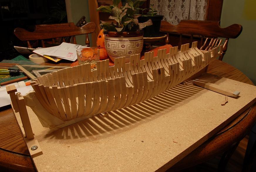
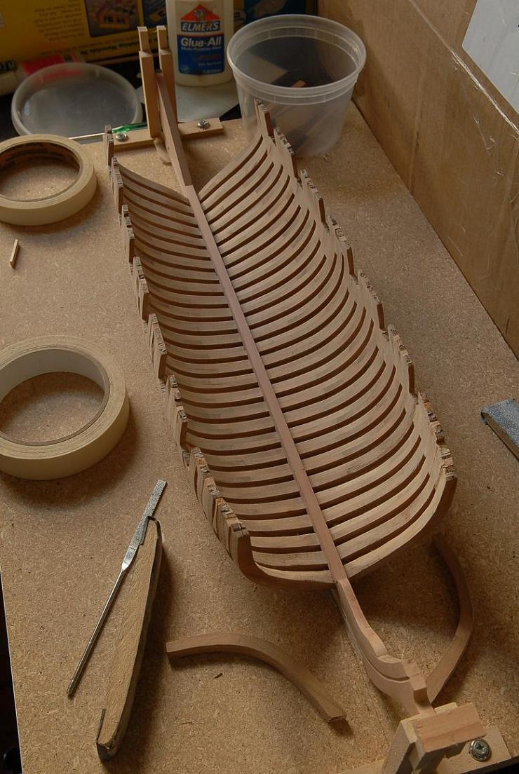
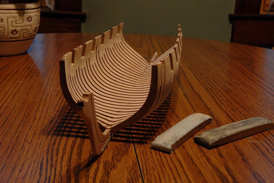
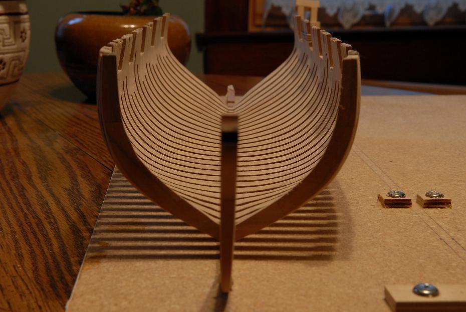
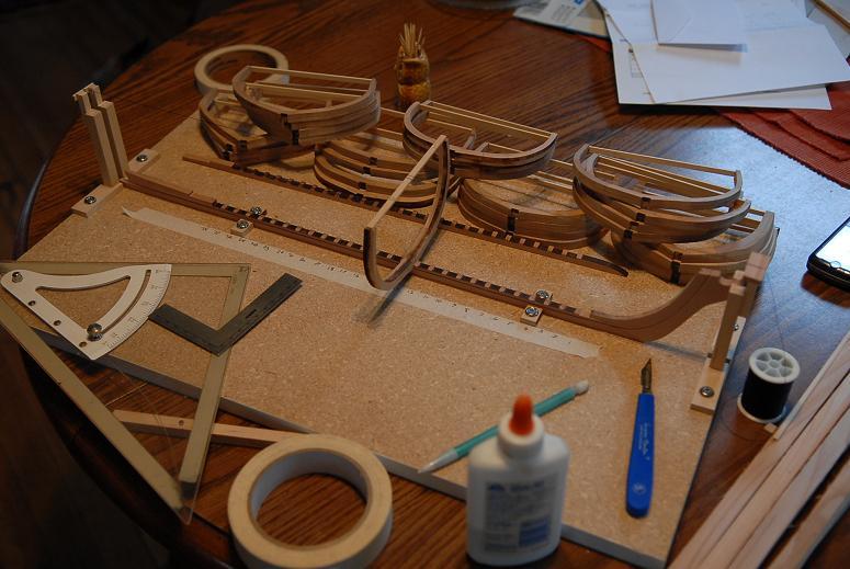
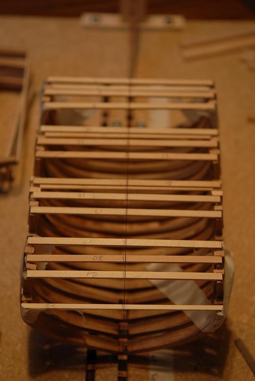
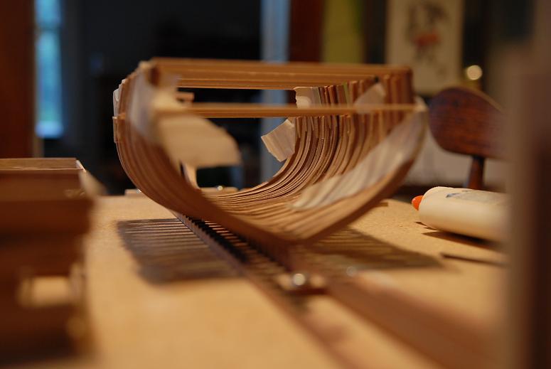
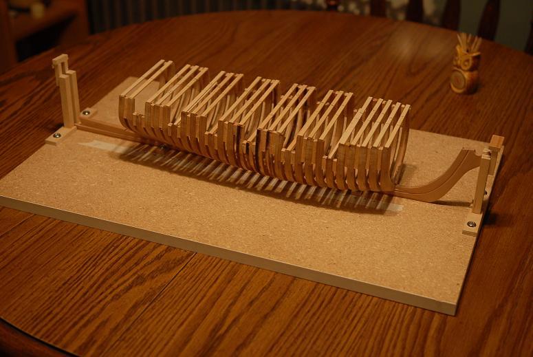
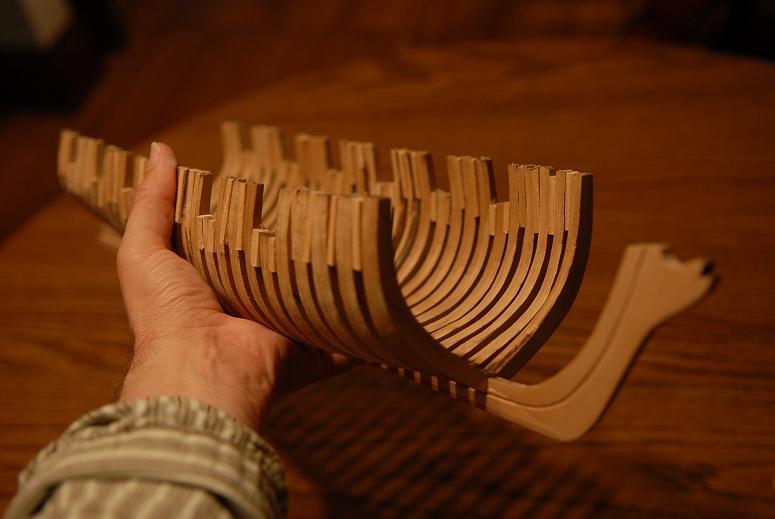
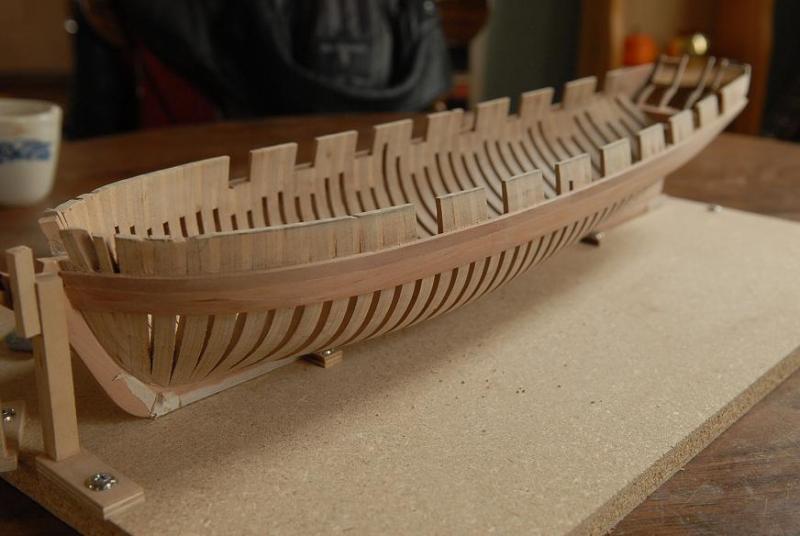
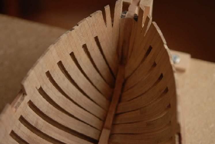
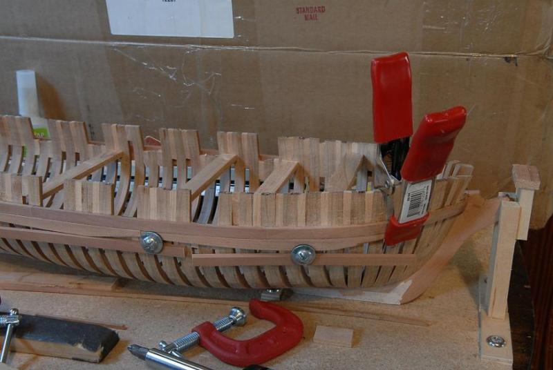
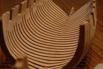
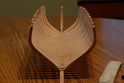
September 8, 2009 The good news: From Dave and Ev at The Lumberyard I have received a replacement carronade for the one I ruined. I have also received a replacement cherry billet for the erroneous beech frames--and even better--it's been laser cut so I don't have to do that by hand. Cutting the pieces out would have been good experience, and I was ready to undertake it, but I'm also glad I don't have to! And the extra pear wood for a new sternpost. Enough extra pear to cover many more mistakes. The bad news: Now that I am ready to dive back into my Oneida build, I am in the midst of a moving mess. I no longer have to split my time between two homes, but it's a little chaotic at the moment as I move all my stuff in. I hope it will only be a short time before things are tidied up enough to get modeling work done. September 12, 2009 At last, some progress to report! My area is cleaned up enough to work. I have assembled the missing frames 12-15, and roughly sanded them. I didn't take all the laser char off, I'm a little nervous that I didn't get the shape exactly right on these, and I didn't want to take off any extra wood yet. Here I am shaping the lower deadwood on the keel. Since the kit is not really designed to be planked, this is some guesswork on my part to figure out exactly how to do this--the bearding line and tapering to the rabbet-- I scratched a new sternpost. In front is the laser cut one, and behind is my new one. This took two tries. It is slightly tapered on the bottom to meet the tapered keel-- And after altering my keel holders to attach a string high enough make it over the tops of the frames, I have glued my first frame on. Hoorah!-- September 13, 2009 I promise not to post every frame I glue, but as long as I'm here-- [Later post on September 13, 2009] Here's the current progress-- One thing is distressing me a little bit: When I placed my first frames they were dead on with the center mark and the string. But as I have glued more on, there is a drift happening. I think it's minor enough, or correctible with the fairing process, but I can not figure out how or why it's happening-- The next pictures are more for the "fun with photography" aspect than useful modeling information-- Here I received this Message from the always helpful Jim Lad, whose encouragement and advice was (and is) always welcome-- Ron, If your frames are drifting off centre then it must be due to: 1) the keel not straight 2) the frames not symetrical 3) the frame notch not central 4) the frames not truly horizontal 5) the centreline mark on the frames not actually in the centre 6) the string having a kink in it. Given that #6 is a joke (alright, an attempted joke); 1) double check that the keel is truly straight 2) if that's OK, measure across your frames to ensure that the centre mark is truly central 3) if that's OK, measure up from the base on each side of the frames to makesure they are truly horizontal 4) if that's OK, lay the frame on a piece ofsquared paper ( so you have some reference lines) and draw around it. Now turn the frame over and place it over the drawn outline. This should show whether the frame slot is truly central and whether the frame is symetrical. If none of the above shows any errors, then I'm afraid you're having a bad attack of gremlins and you'll have to live with it!! John September 14, 2009 After gluing about 8 frames I noticed that the first frame I had glued was no longer centered. So something in my technique is throwing things off. I have been compromising between exactly centering the new frames, and having them line up with the previous ones (which have become slightly off center--at the most 1mm) The 'beams" are remaining pretty level. The frames themselves are pretty rough,there are variations in outside width even more than the "centering" deviation. John, your list of things which may be "off" makes me laugh (as opposed to crying). There are so many possiblilities of inaccuracy, all I can say is I've tried to get each of those things right. There is a little bit of "play" in how straight the keel is held up. It's only held vertical by the stem, as the sternpost is not on yet, so if the keel is getting twisted somehow, that could also cause the center of the frames to move off. (add to the list as #7) But, I'm going to blame the string. And if it's gremlins, I'm going to sic the cat on them. September 16, 2009 I determined that the drift off of the first few frames wasn't getting any worse, and the new frames were lining up well, so I decided to forge ahead. I'm now done gluing the full frames. The directions recommend sanding the hull, at least on the inside, because it's easier to get at now, before the cant frames go on-- The hull so far seems fairly sturdy, but I have a slight (mostly unreasonable) dread of it popping apart in my hands! I'm chuffed to bits! [This drew messages chiding me for my 'pommey' slang.] Ron


-
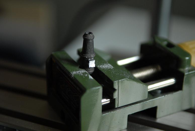
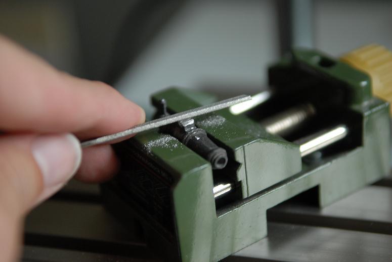
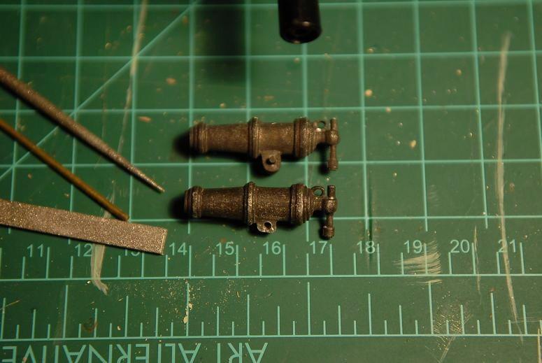
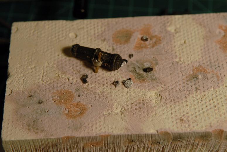
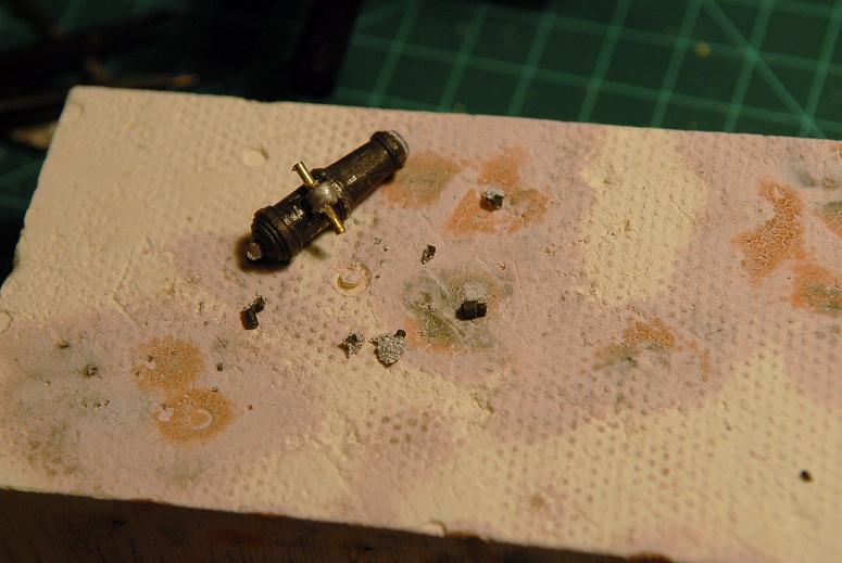
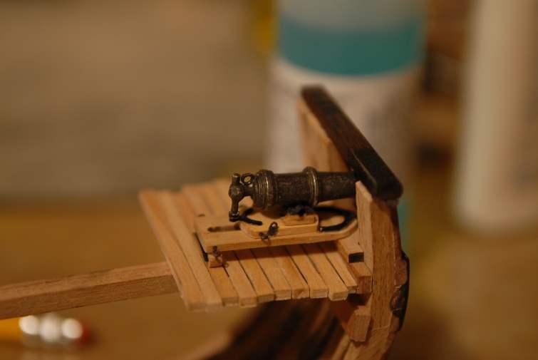
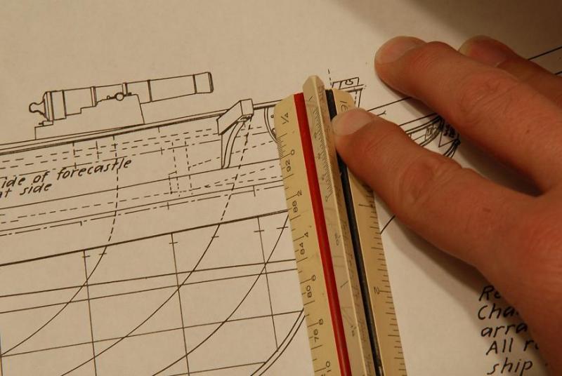
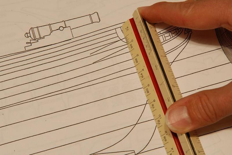
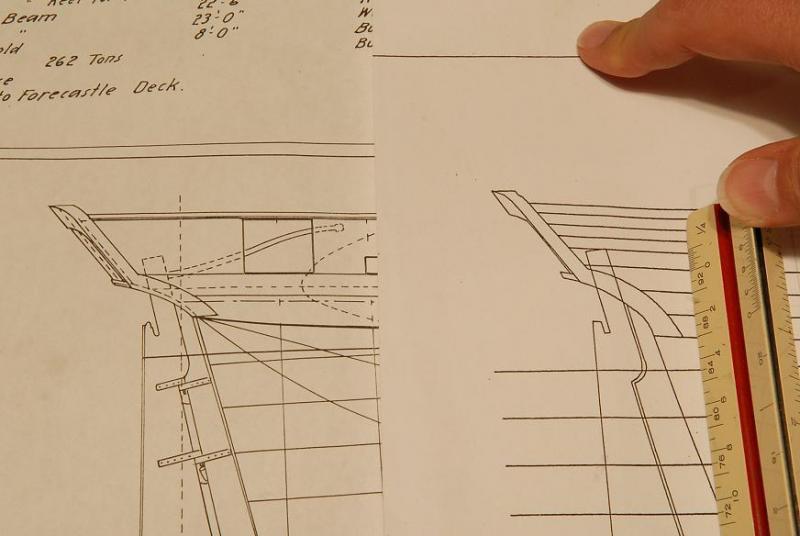
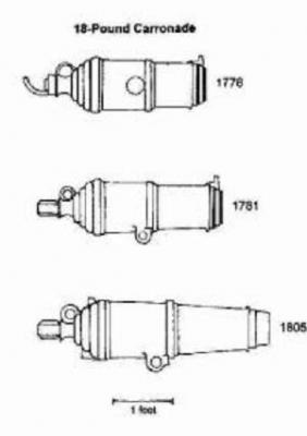
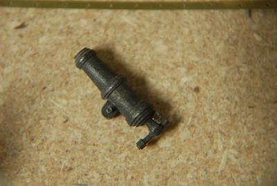
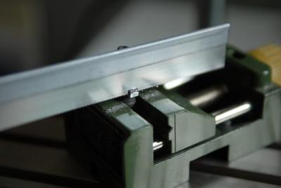
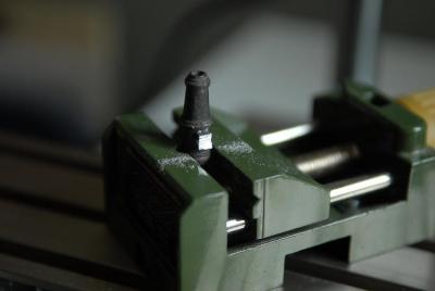
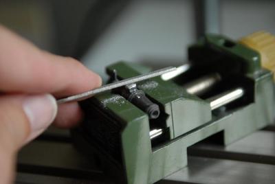
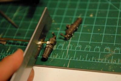
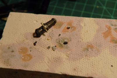
August 18, 2009 Oh dear. Today's episode is a comedy. I recently heard a definition of comedy as "a man in trouble." I am back to work on the carronades. This is an illustration of carronades from various periods. The thing to note is the location of the trunnions. In the versions with trunnions on the bottom, they are just about tangent to the edge of the barrel-- Now here is the Oneida kit carronade. Not bad, but look where the trunnions are. No wonder the carronades seem to sit very high. The trunnion is way off the edge of the barrel-- The other thing you can't tell from the photo or illustration is that the trunnions on the kit carronade are not long enough. They don't reach the end of the support brackets and metal cap square. There is a little hole where the end of the trunnion should project just a little. So, for these two reasons, I decided to make an alteration. First I sawed off the trunnions. Then I sawed the lug shorter-- Then filed it up nice, and drilled a hole for the new trunnion-- Here you can see a comparison of the lug and trunnion placement. I think mine is turning out quite well. On the left side of the picture you can see a 1/16th inch brass tube that I will cut to the right length and solder into the lug. Then I'll blacken it, and it'll be great-- Here's my brass rod trunnion in place, being sawed to the approximate length. I'll fine tune it with a file, and then have a prototype to do the other carronades with-- I stand the little carronade up on my soldering block, and lite my little torch. As I start heating the brass up, watching for the silver to melt, I am horrified to see instead the carronade lug slump, as if it's starting to liquify! I stop immediately, shut off the torch, wait a second, and gingerly touch the barrel of the carronade. It's very hot. So I grab some needle nose pliers and pick up the carronade by the cascabel and height adjusting screw. It crumbles into pieces. If you never make mistakes, you never learn anything. I've learned you can't silver solder to the carronades in the kit. [Work on the carronades was abandoned for a while] Ron


-
Thanks, Mark. It's interesting re-living the build. Thanks, Don. I encourage you to start a log of your Emma C. Berry! Ron
-
Hi Andrew! It's great to see another Alden sloop a-building. Really brings back memories. Your model building skills definitely look more than equal to the task, but if you have any questions about the sloop, I'm happy to help. I should have access to my old photos of the build itself, soon. (They've been trapped on a derelict hard drive). I wasn't planning on reconstructing the build log, but I can make the photos available to you if you want them. Good luck! Ron
-
What is your favorite hand tool(s)??
rlb replied to Modeler12's topic in Modeling tools and Workshop Equipment
lol You mean like this? Ron (We've probably hijacked this topic enough!)
-
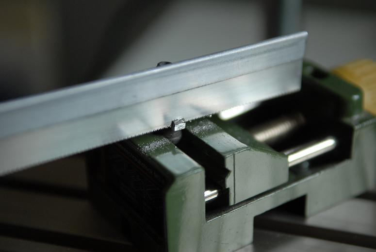
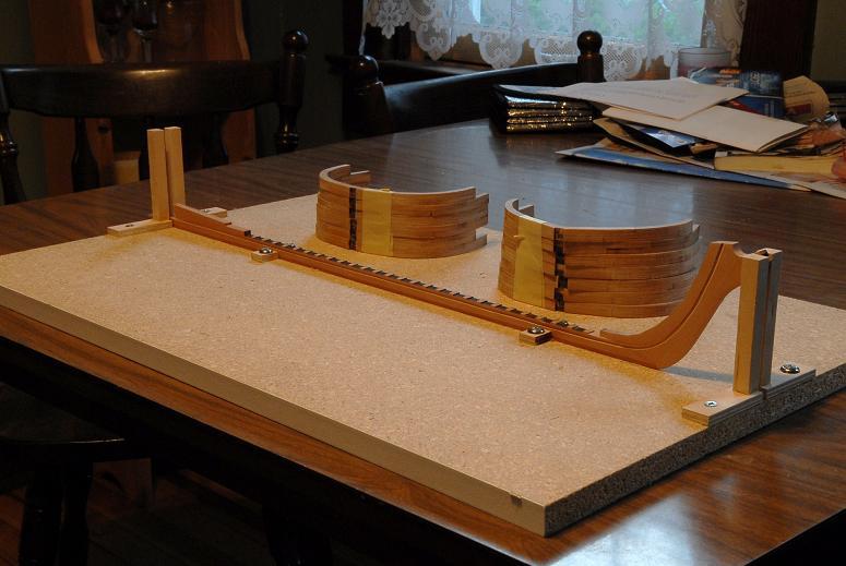
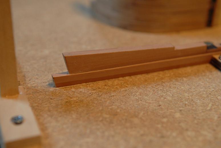
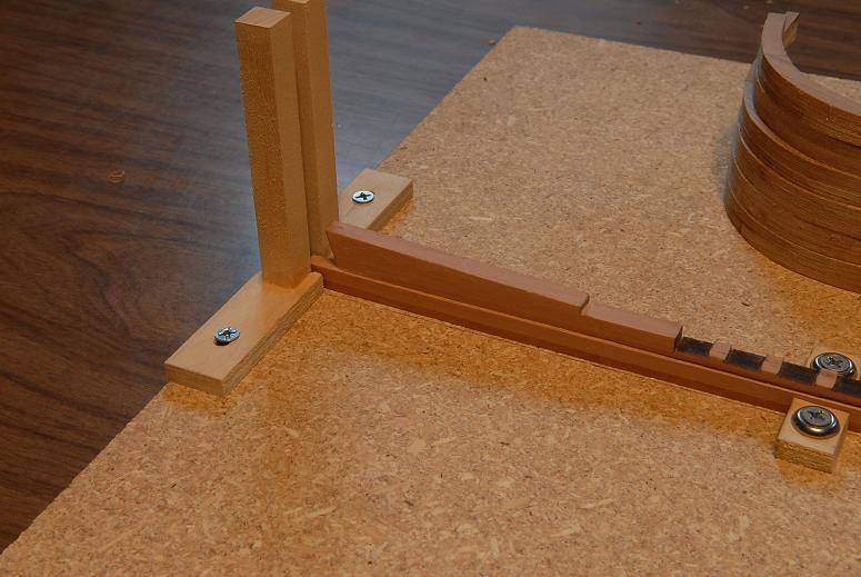
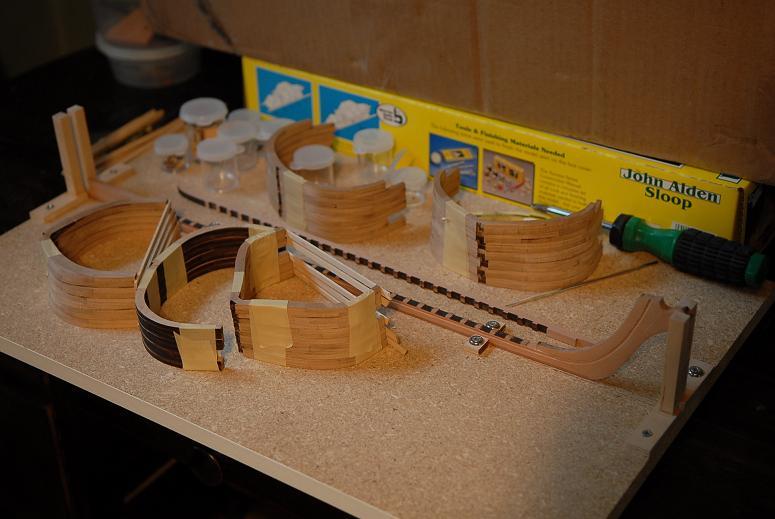
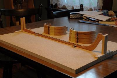
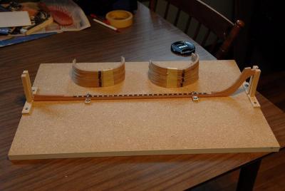
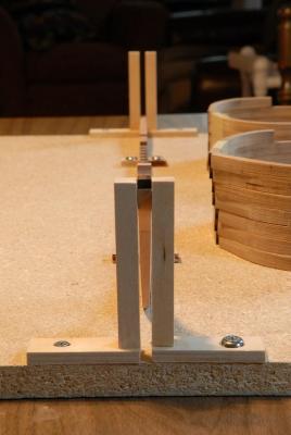
August 5, 2009 I have to deal with a minor setback on Oneida. Some of my cherry framing is not cherry. The billet containing frames 12-15 was actually beech, though I didn't figure that out until I had glued the frames up-- The two woods are very close in color. The beech is just a bit lighter, and the grain has tiny dark flecks, which actually make it look a little like miniature oak. At first I though it was just an unusual piece of cherry, but after a little research I found out it was beech. A couple months ago, while waiting for my kit to be shipped, I came into contact with a gentleman in Texas who was also waiting for his Oneida. When I discovered my mismatched frames I shot an email to him, and lo and behold, he had specified his frames in beech! Just last night he checked his kit to see if he had received one billet of cherry frames in place of beech. It appeared that he had! Alas, his cherry piece contained frames 8-11. We couldn't just exchange frames. So now I have contacted The Lumberyard for a replacement cherry billet. I can't bear waiting another 3 months to have it laser cut, so I will have the pleasure of cutting the futtock pieces out by hand. I also tried in vain to find a big enough area in the leftover parts of the keel/deadwood/sternpost swiss pear billet to cut a longer sternpost. It was so close, but not possible. I will have to buy some more wood to make a new sternpost. All this explains why I detoured into building the carronade carriages while the hull framing is on hold. I can cut the port side rabbet while I wait, but I am a little nervous after my less than stellar job on the starboard side. August 10, 2009 While I wait to get my mixed up frames resolved, I made some adjustable uprights to hold the keel-stem-stern straight. These pieces could be made more sturdy, with some 45 degree bracing, but I made sure they were as square as I could make them, and I think they'll do. I can reinforce them if I find it's needed. [Jeesh, how hard would it have been to add some bracing--sometimes I'm so lazy!]. I ran out of those little rings that the screws sit down in--I'll get some more and then it will look more "polished". My board is barely long enough! [This was a left-over board from my first model that I wanted to reuse]-- If I line up exactly end to end, it looks straight and plumb-- I cut the keel down to the rabbet line, which now makes my sternpost about 1/16th of an inch too short. I could probably cheat and add some wood to the top of the sternpost, where it might not even be visible. But I'm not sure exactly how that's going to come together, so I probably will cut a new one. Since I have to wait for the cherry wood for the frames, I might as well get some extra pear for a new sternpost. I also can't seem to locate the wood for the rudder! I cut the rabbet on the port side. I didn't take any pictures, but it came out about the same as the starboard side which you can see here. It looks fine unless you study it closely!-- Parts and pieces-- The frames with the laser char still on them are the beech frames that I need to replace. The carronade parts are in the little plastic bottles. I'm held up on those, too. I don't think the front pivot part of the carronade carriage is accurate, and I think I want to do something different than what's supplied in the kit. I need to do some studying of the deck height, waterway and gunport sill heights, and how the front of the carronade sits on the sill. I might as well file some more blocks while I wait for my replacement wood. Ron


-
What is your favorite hand tool(s)??
rlb replied to Modeler12's topic in Modeling tools and Workshop Equipment
Excellent, Jay. I'll check those links out. Ron -
What is your favorite hand tool(s)??
rlb replied to Modeler12's topic in Modeling tools and Workshop Equipment
Got it, Michael. I will do a little research online before I tackle it. Ron