Check out our new MSW Sponsor Innocraftsman
×


rlb
-
Posts
655 -
Joined
-
Last visited
Content Type
Profiles
Forums
Gallery
Events
Everything posted by rlb
-
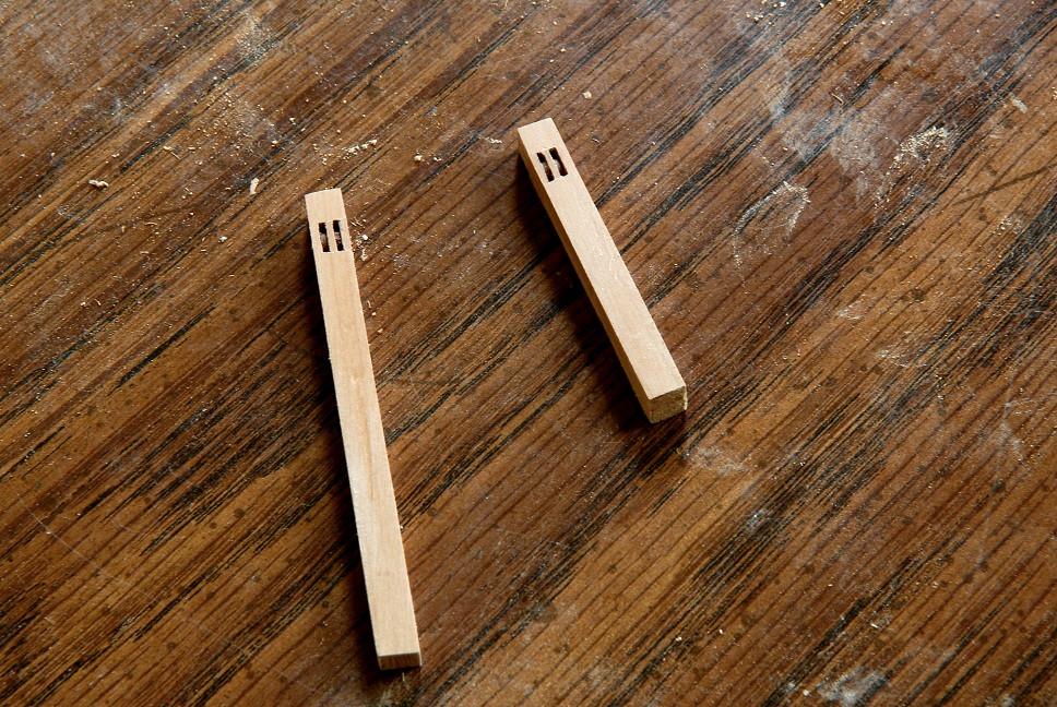
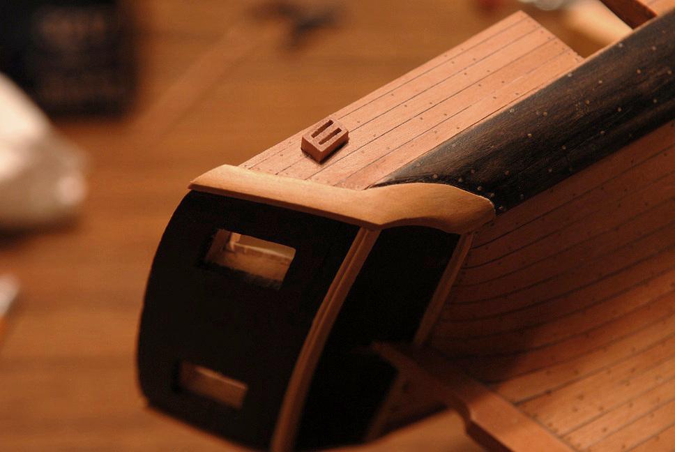
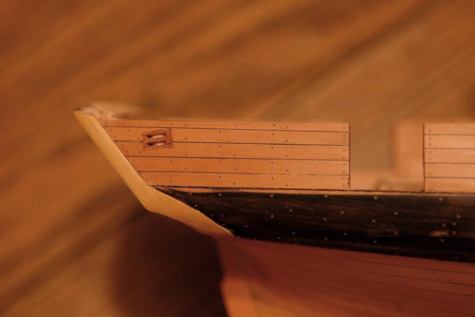
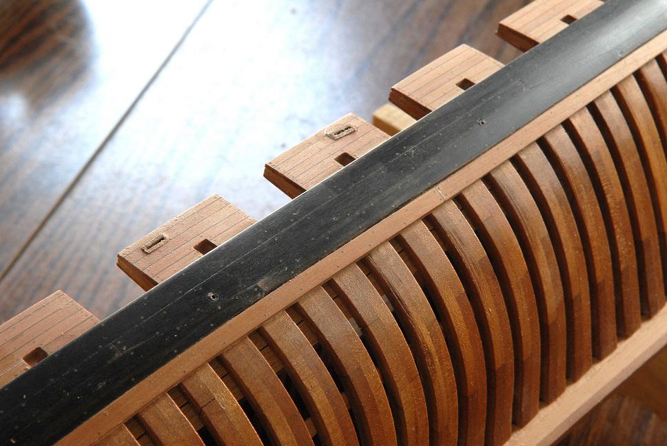
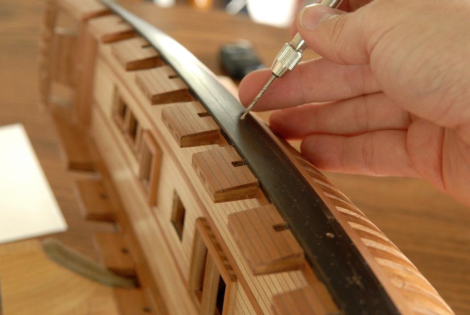
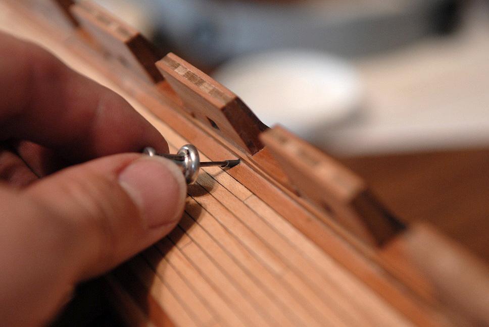
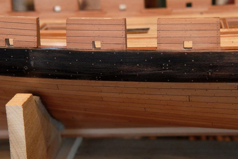
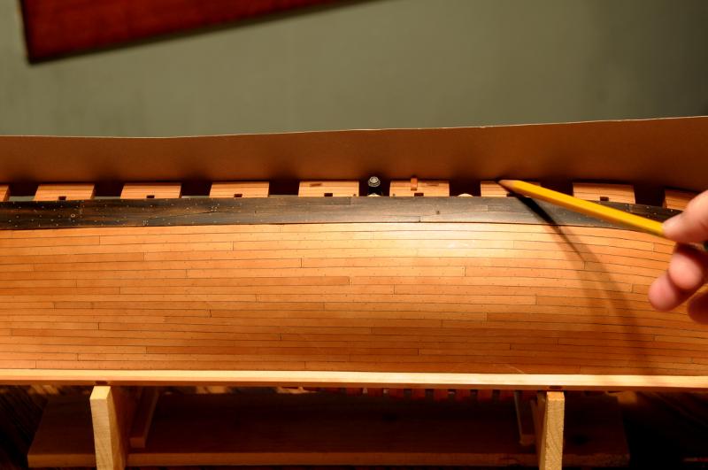
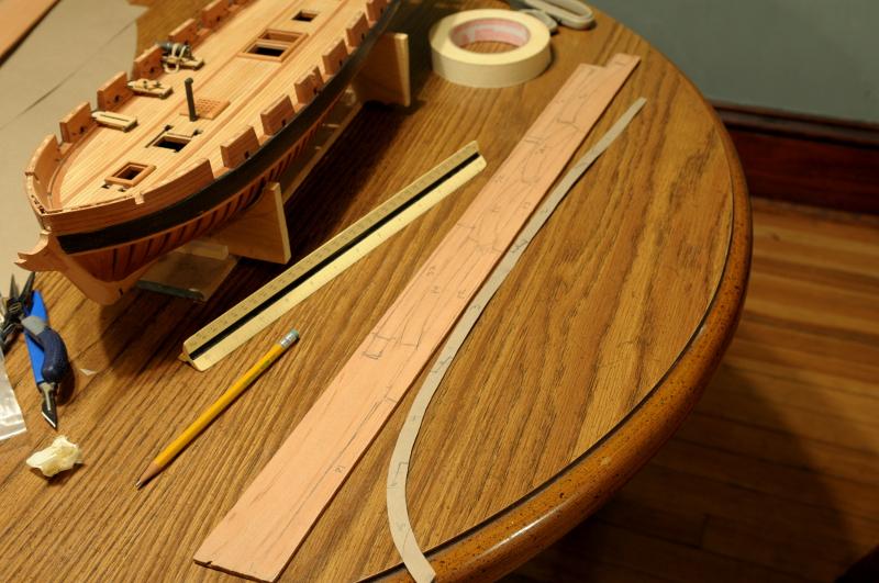
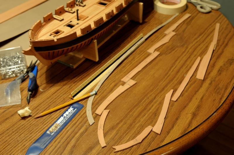
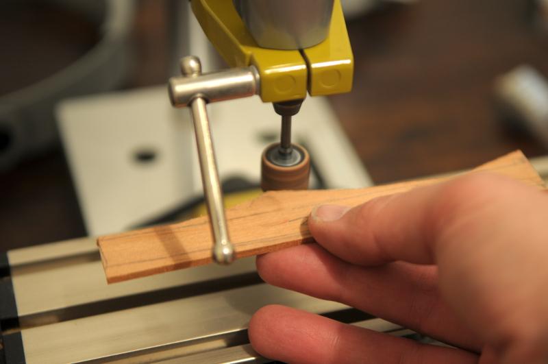
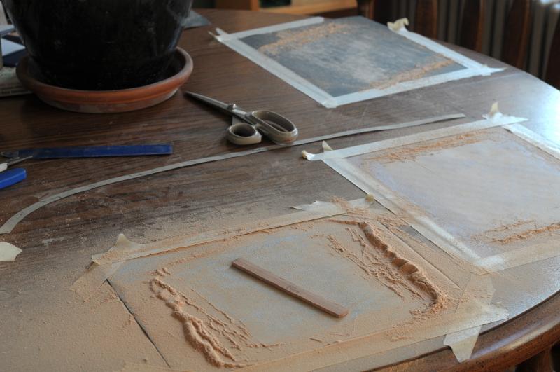
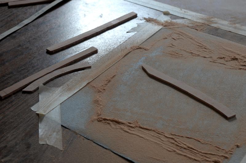
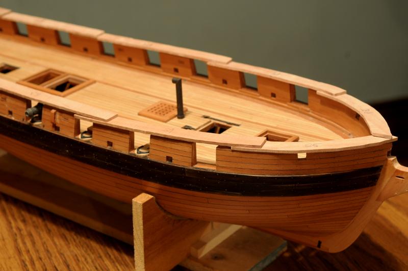
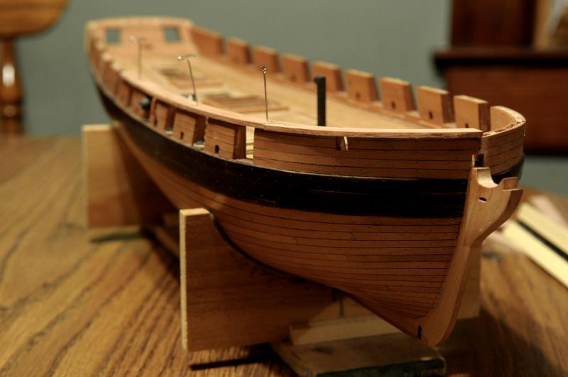
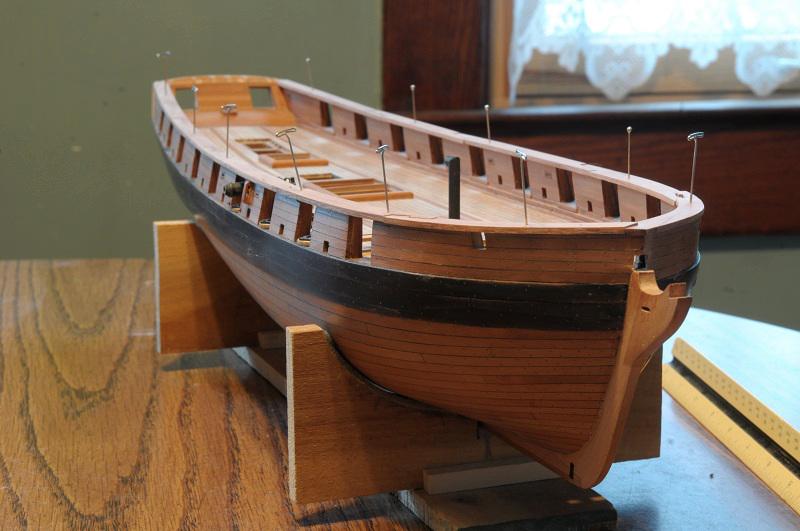
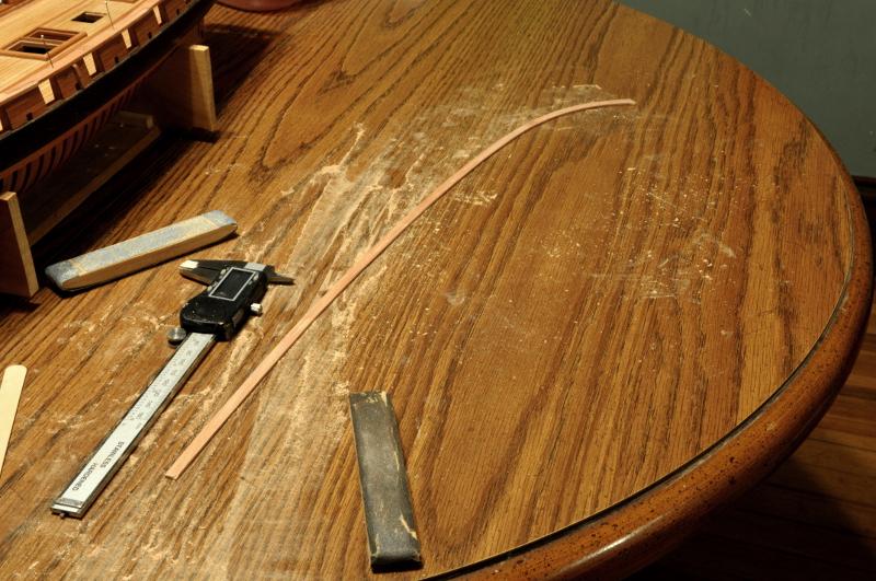
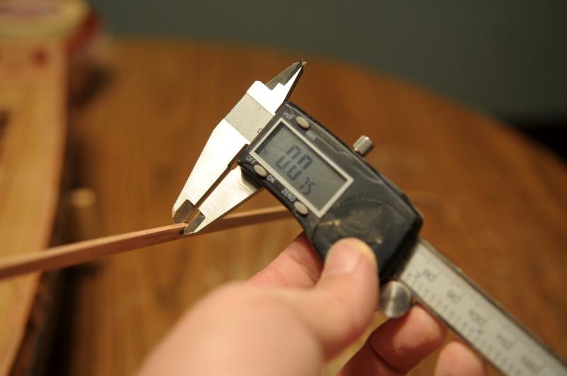
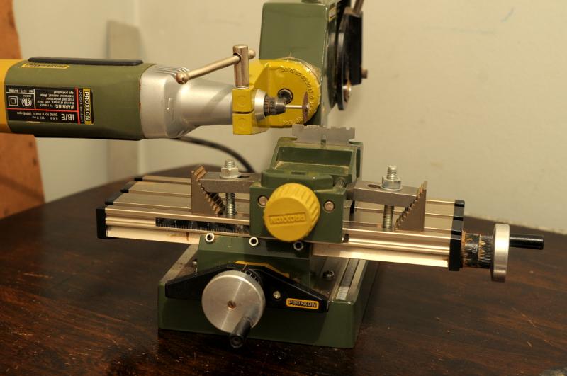
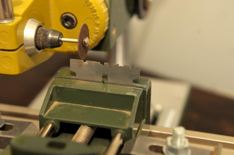
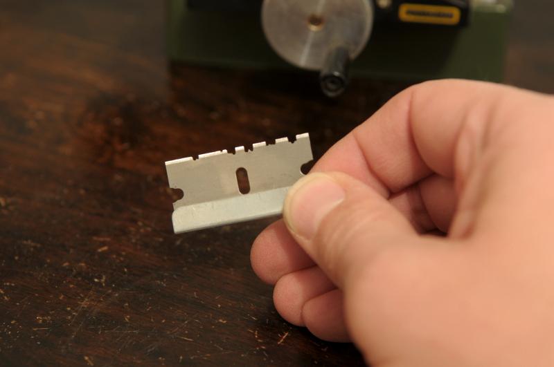
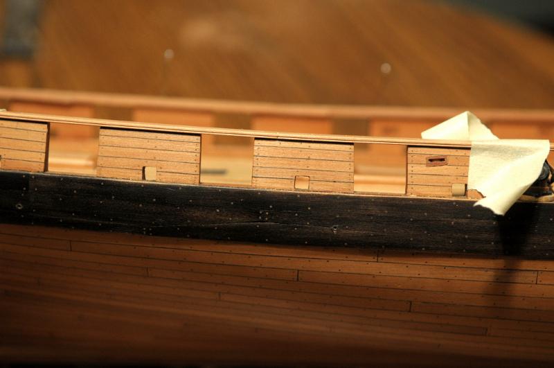
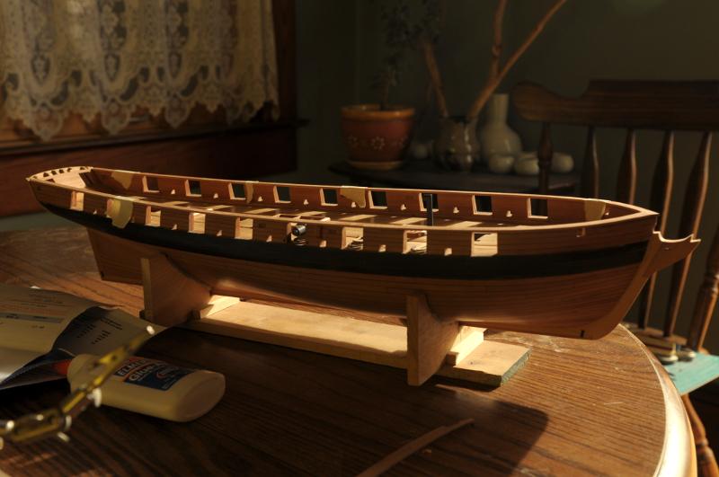
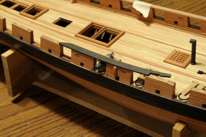
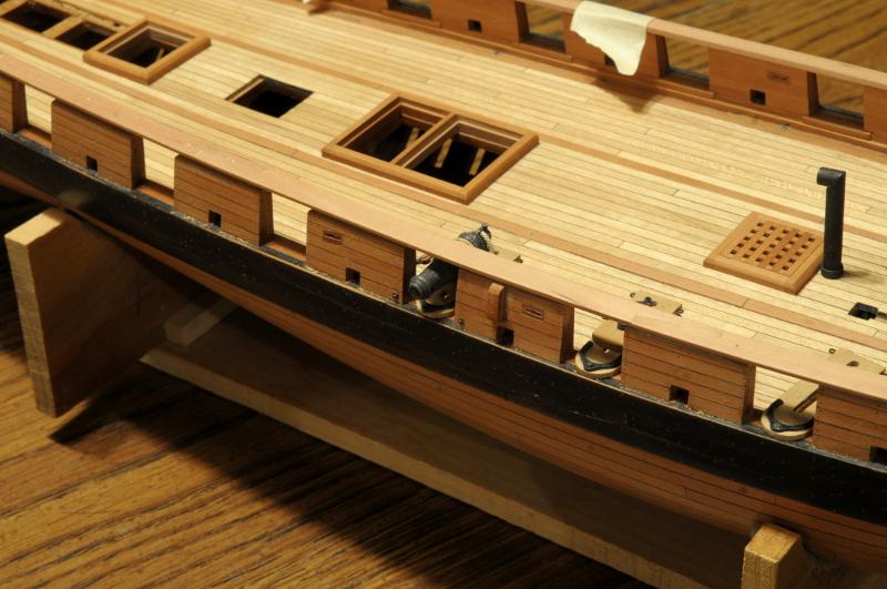
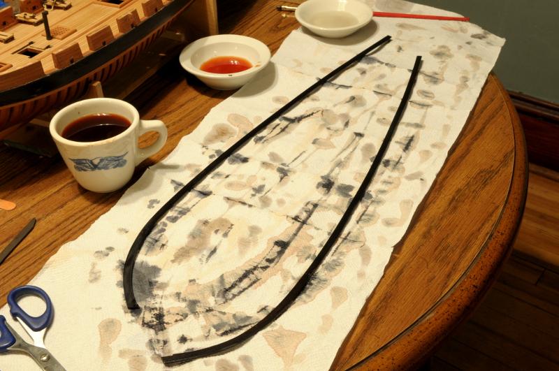
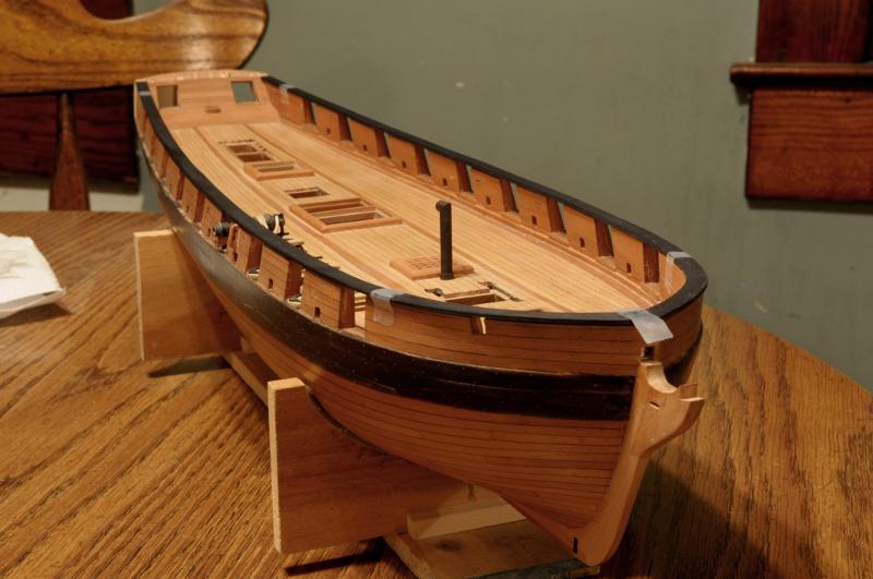
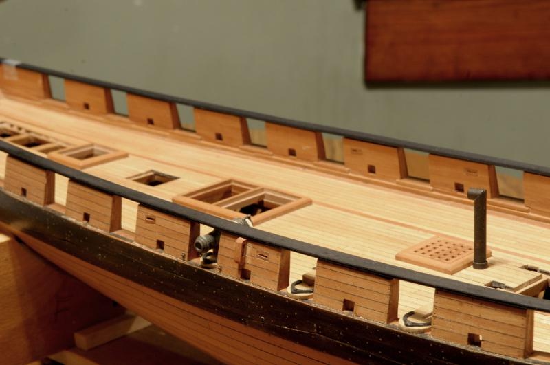
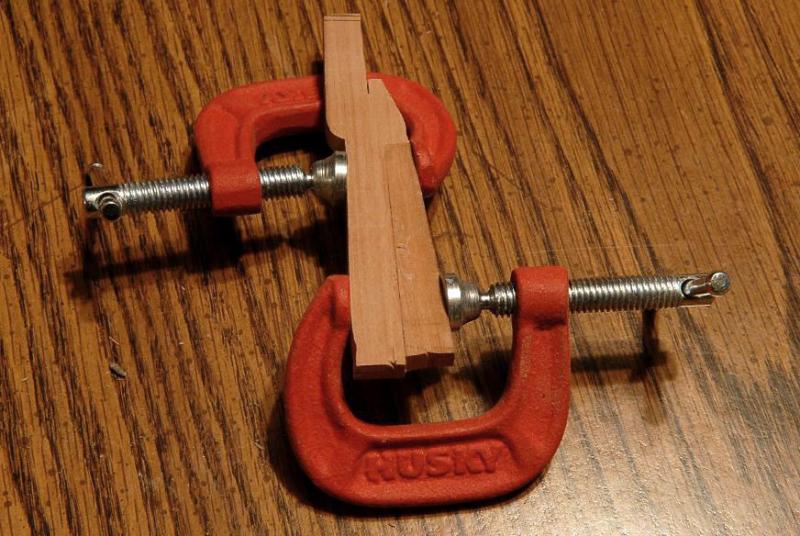
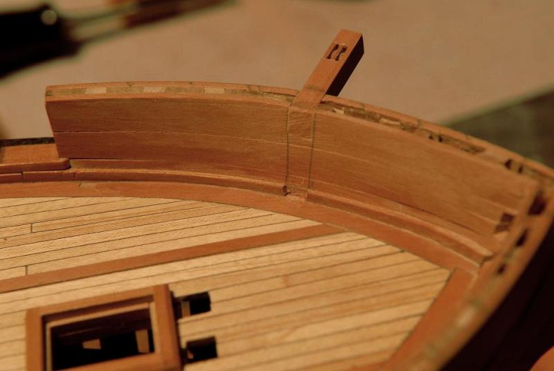
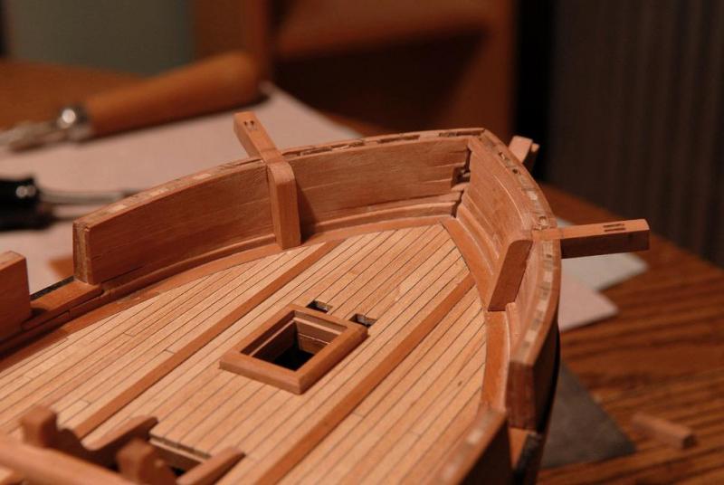
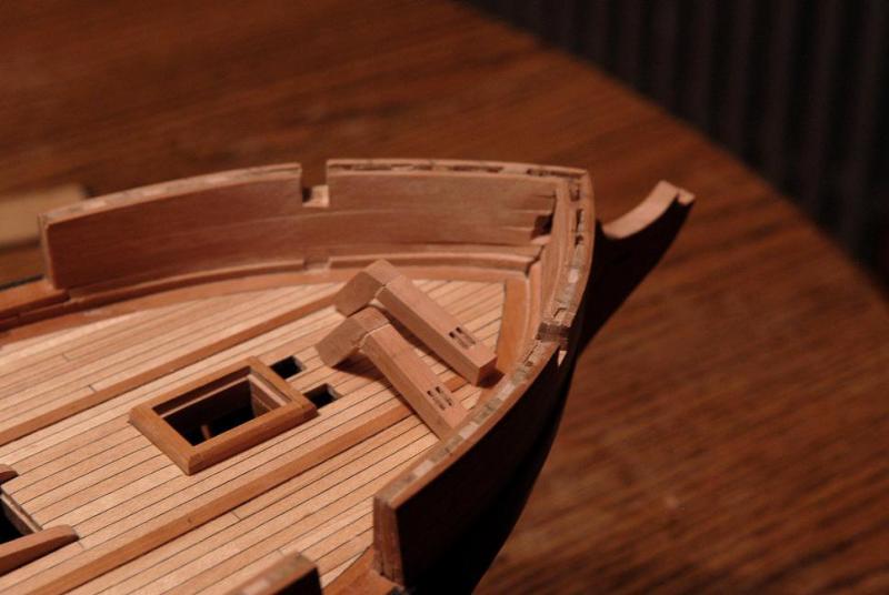
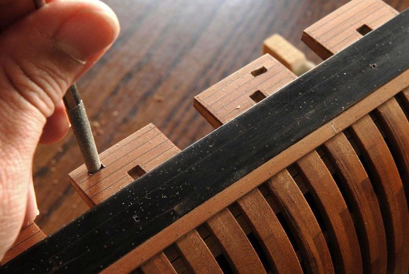
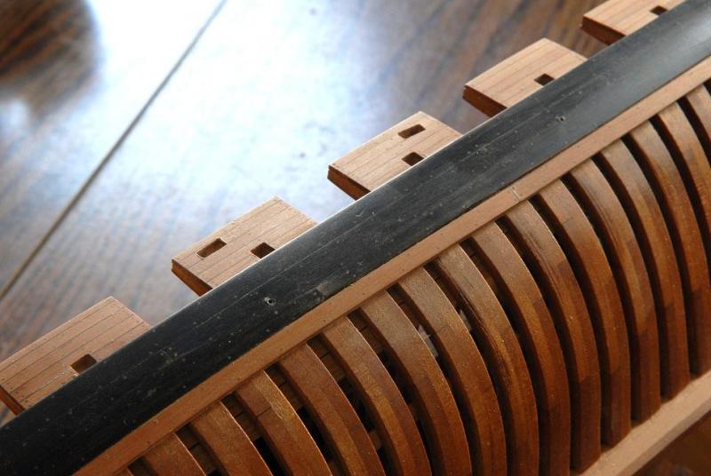
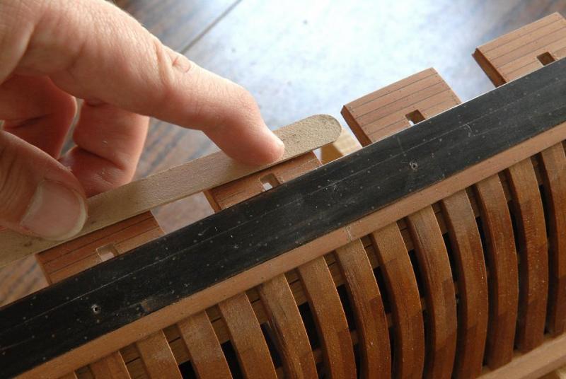
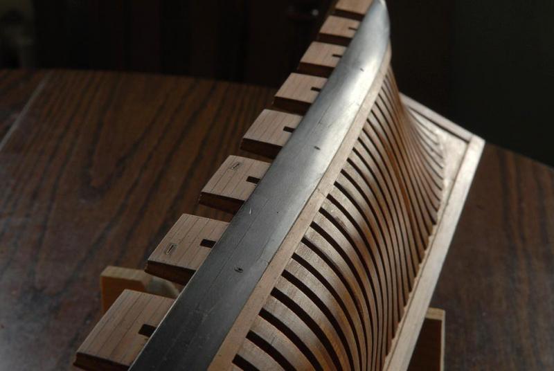
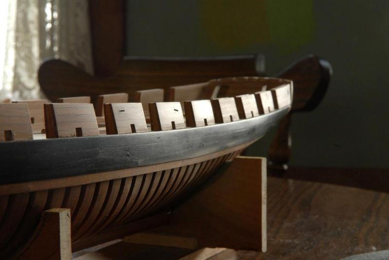
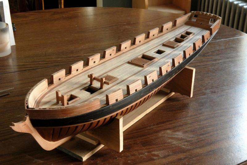
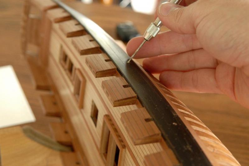
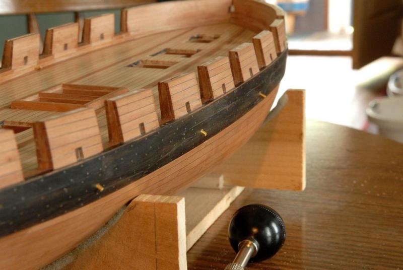
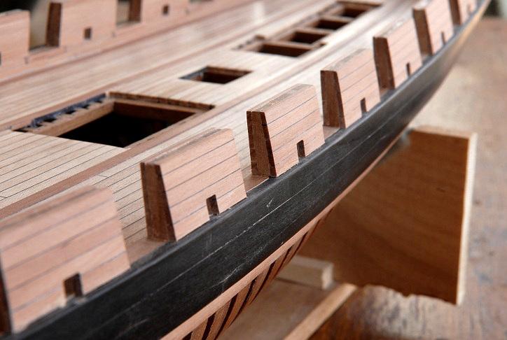
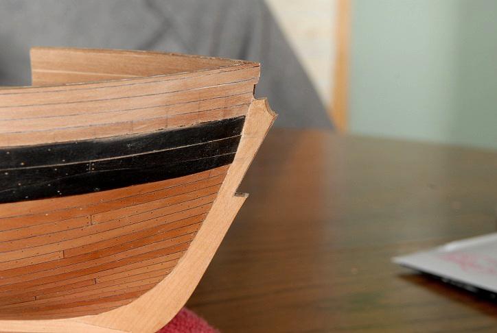
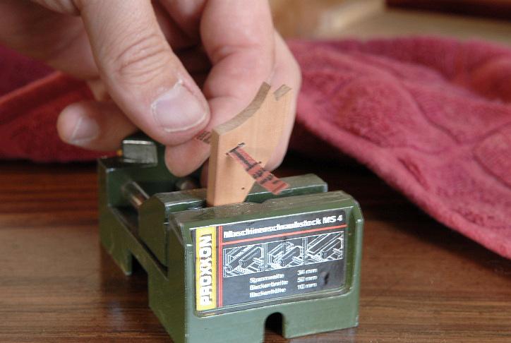
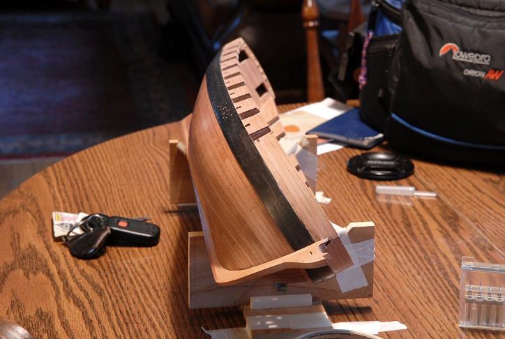
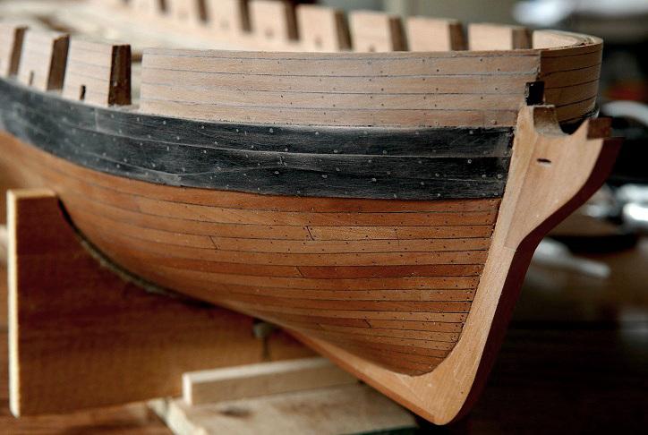
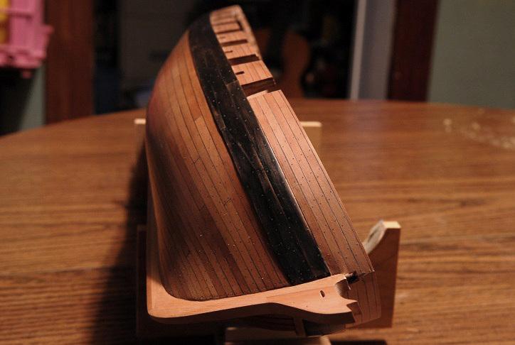
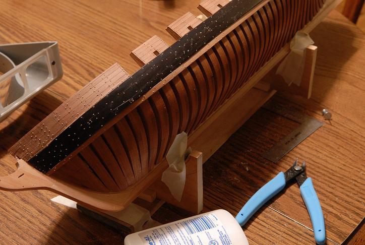
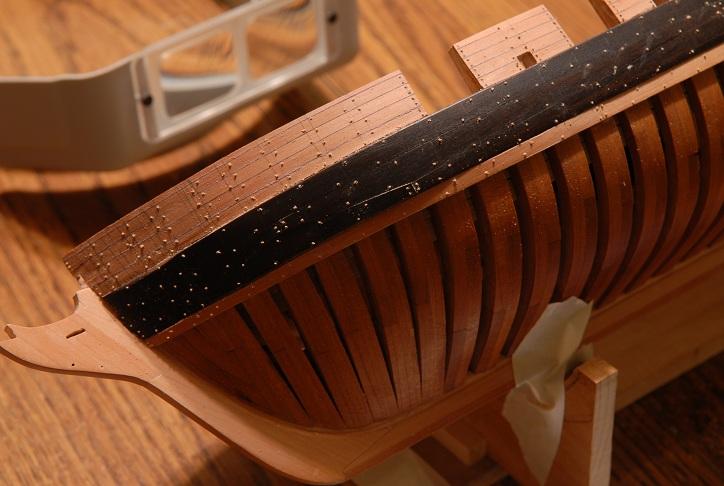
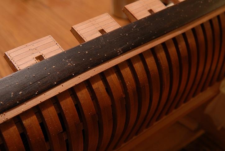
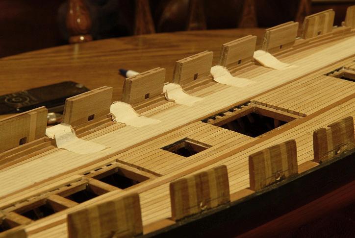
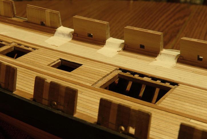
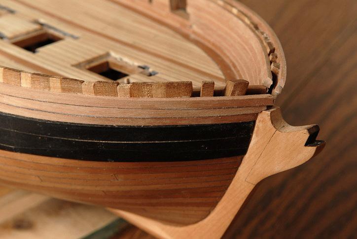
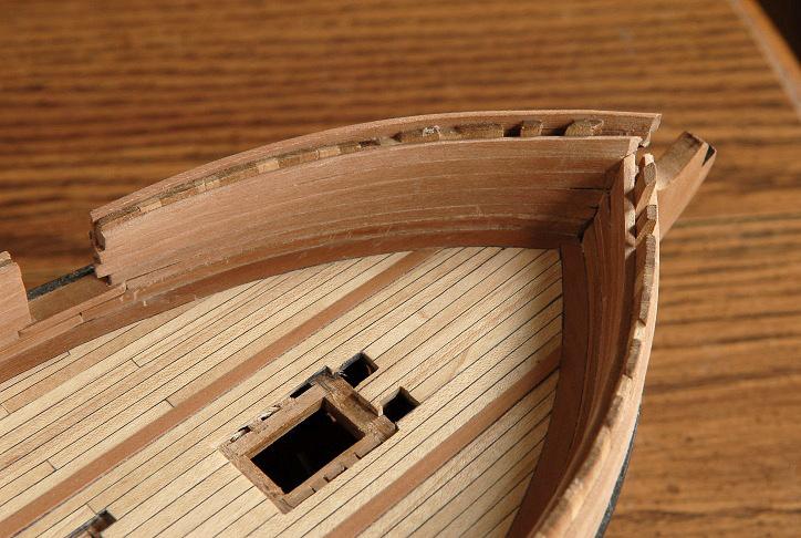
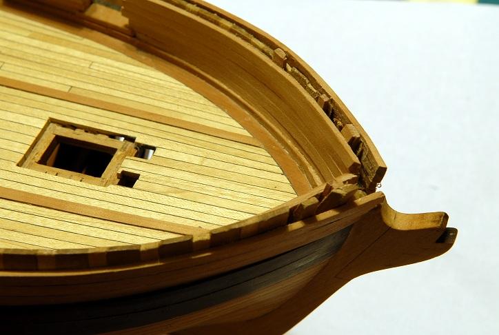
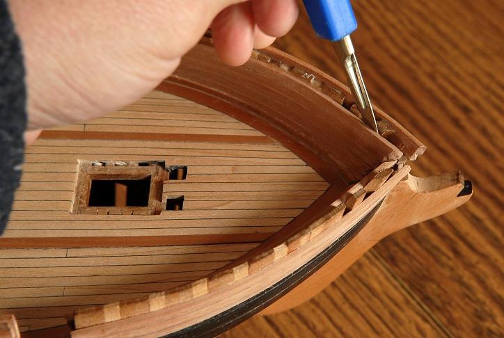
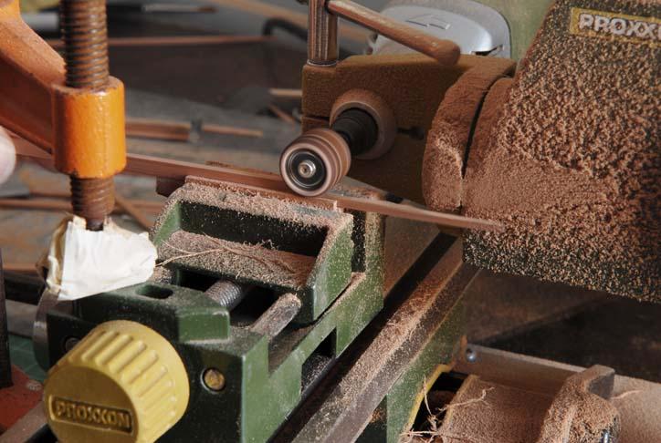
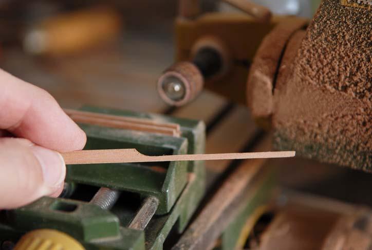
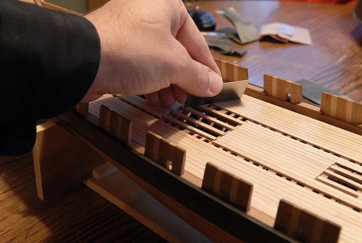
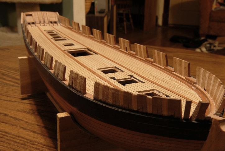
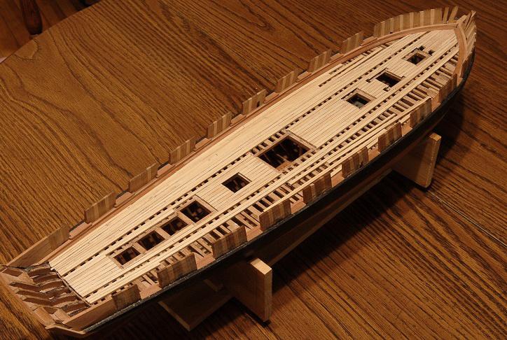
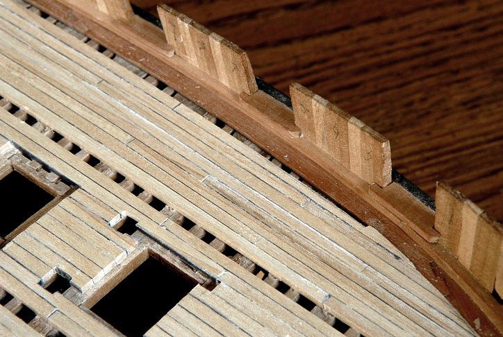
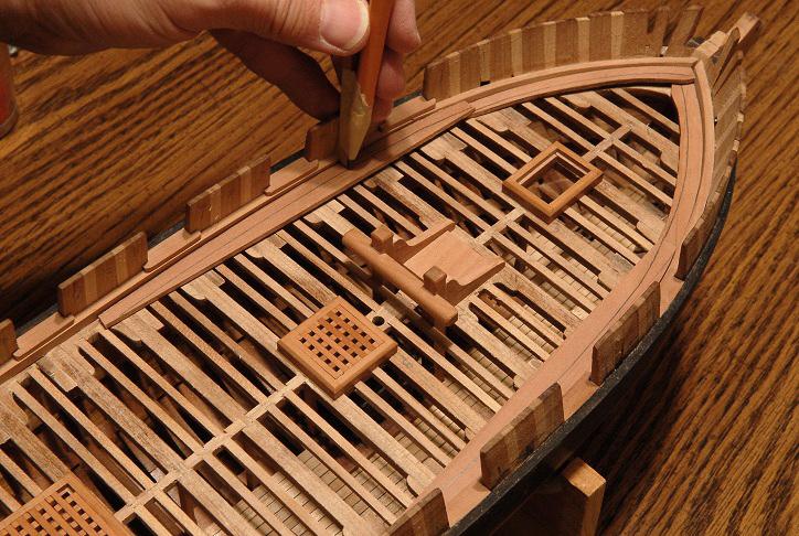
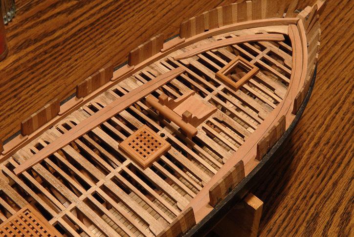
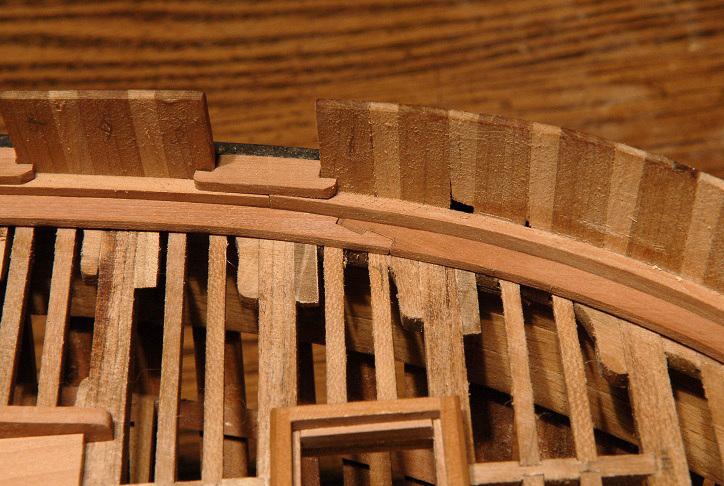
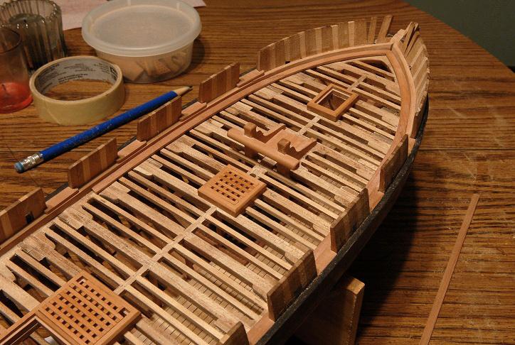
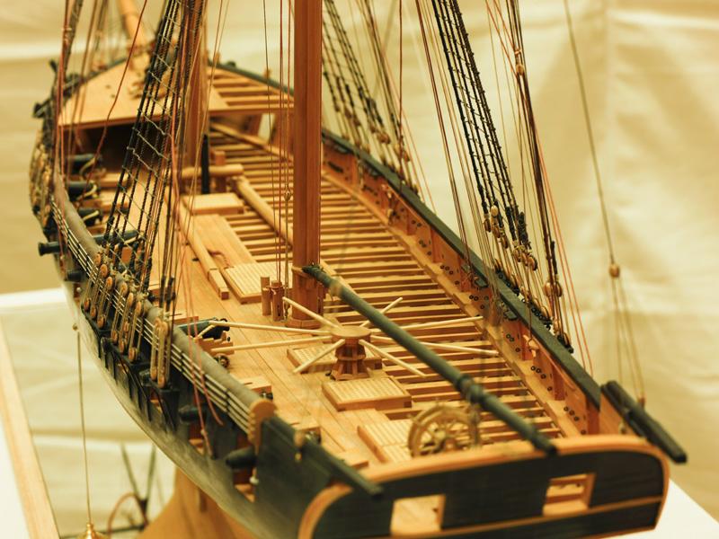
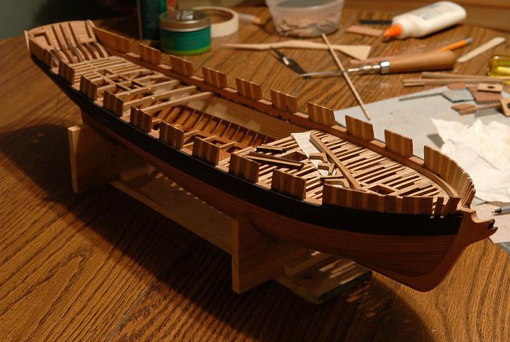
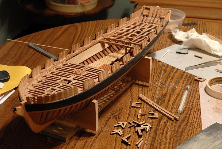
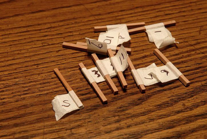
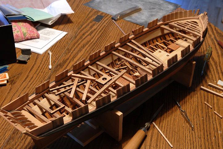
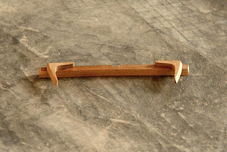
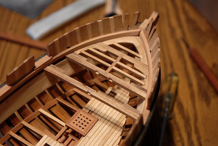
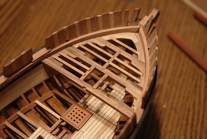
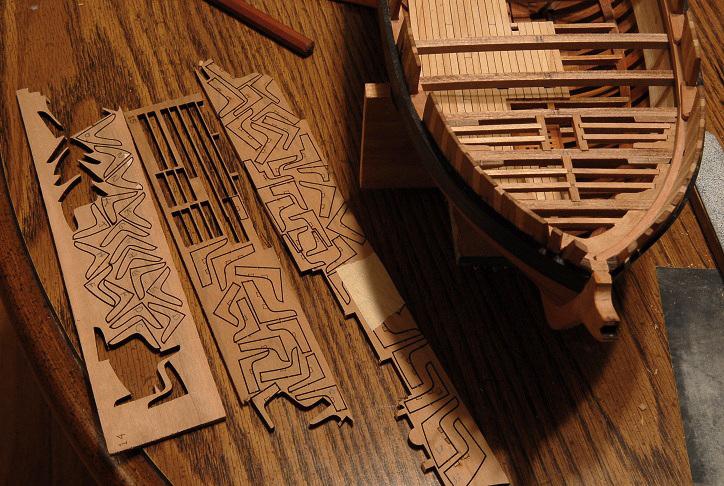
 January 2013 As a result of a New Year's Resolution (which is looking like it will be the most sucessful one I've ever made!) work was begun again. The first order of work was the cap rail-- The stock I had was too thick, which required sanding the pieces down quite a bit. Deja Vu with the hull frames. The pear for the cap rail is much harder than the cherry of the frames, and this work took frustratingly long. Oh, for a thickness sander!-- Sanding to shape, and cutting scarph joints-- After cutting all the scarph joints, the pieces were glued together-- Sanded again and checked for thickness-- A razor blade was ground to scrape a profile into the cap rail-- The profile used for this particular purpose is the one on the left-- The rails are test fitted to the bulwarks-- Now experiments are done to test whether the rails should be left natural, or stained black-- This was a tough choice. I really believe both ways look good. I decided to go with black rails, since that is what was originally in my imagination, and what I've also seen on a lot of other models-- Ron
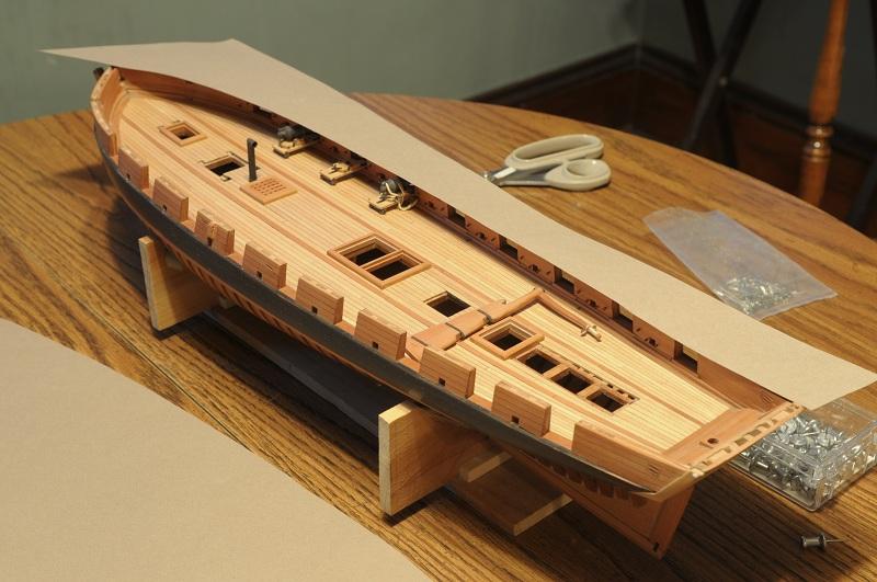
-
Hiatus For 18 months, from July 2011 to January 2013, no work was done on the model though it remained poised in the work room-- It was just a long lapse in motivation. I did periodically look in on other builds, though very rarely posted.

-
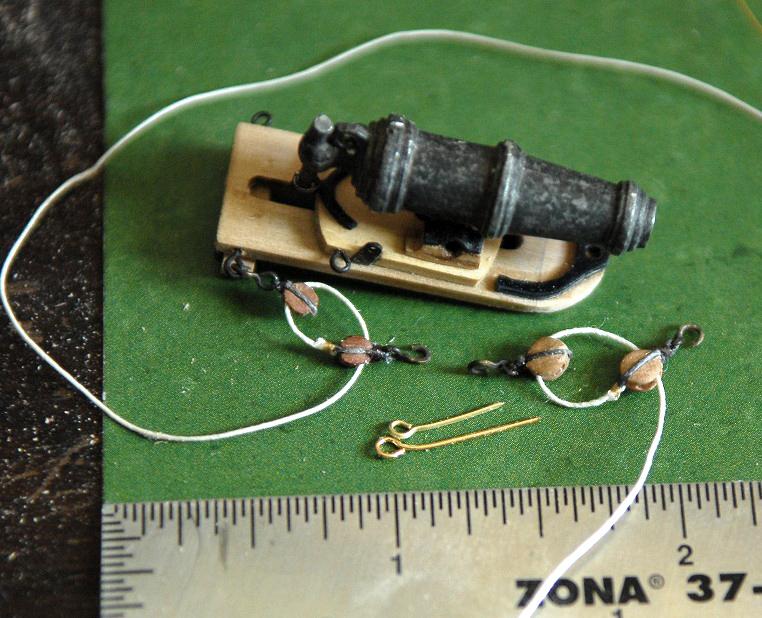
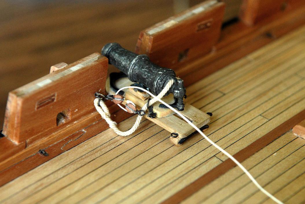
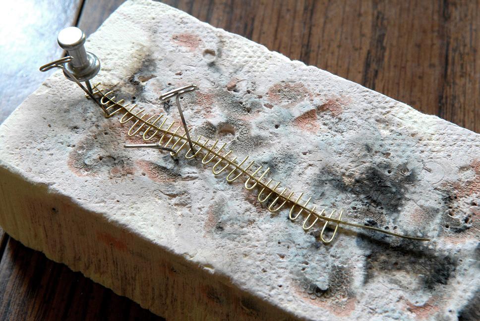
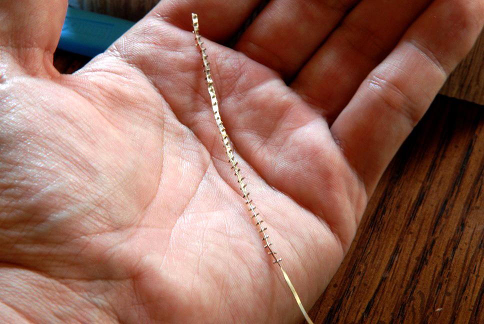
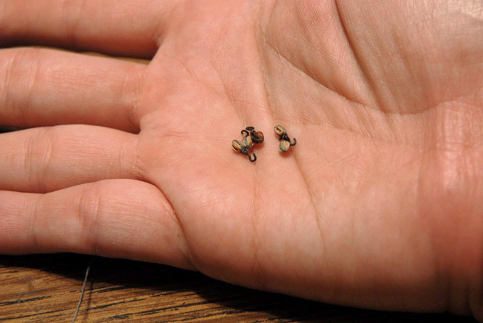
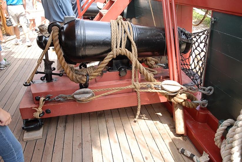
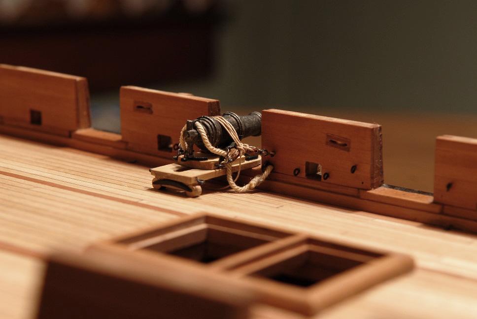
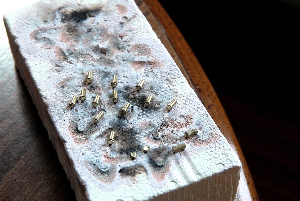
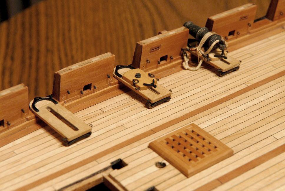
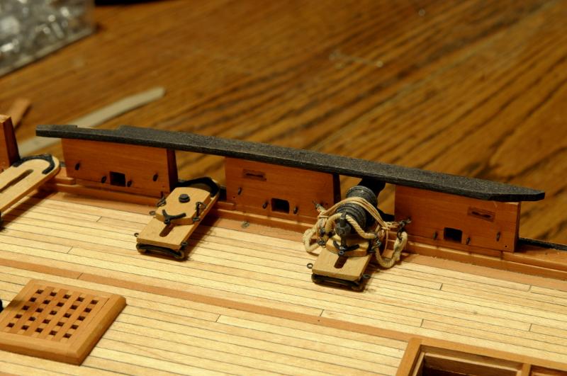
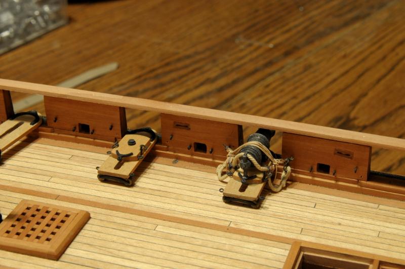
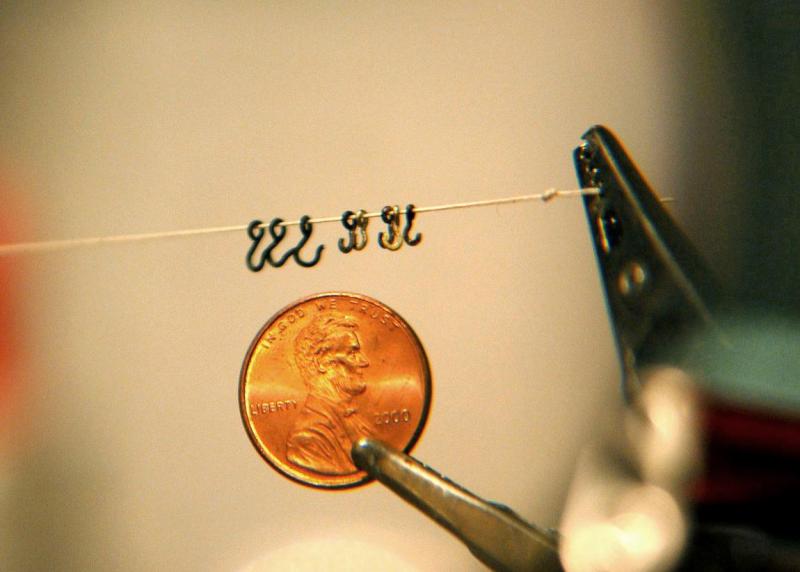
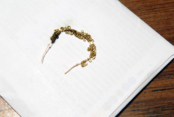
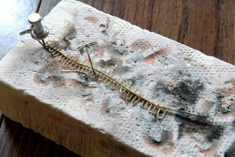
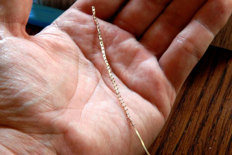
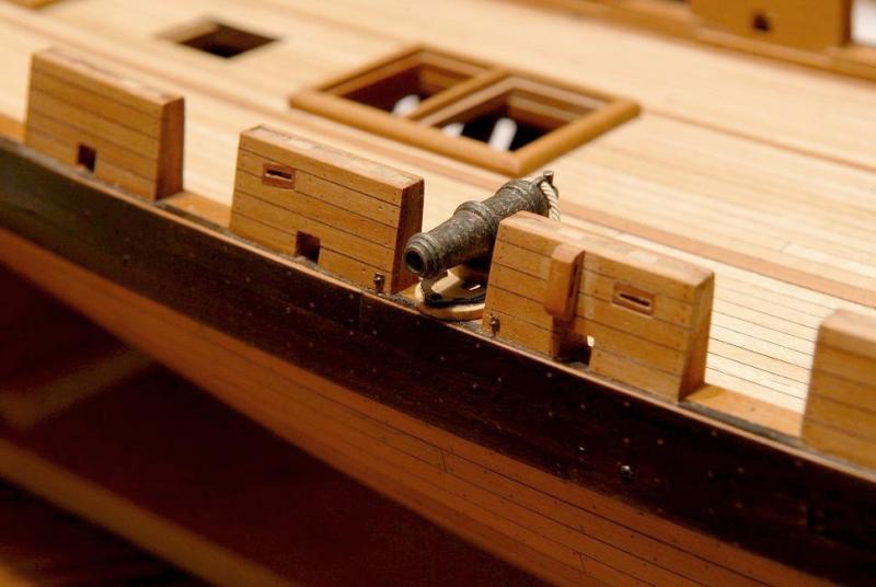
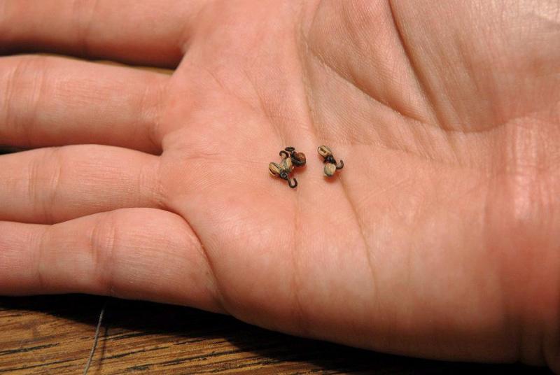
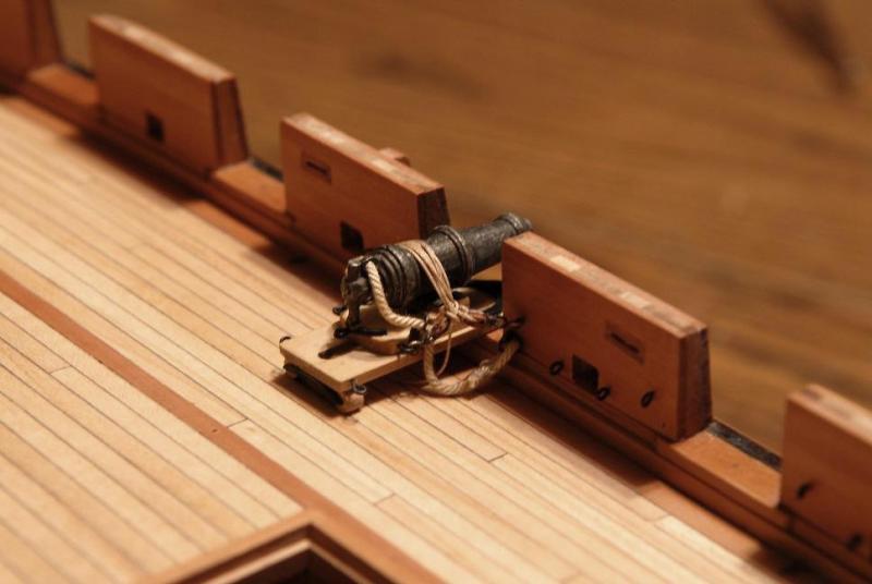
July 2011 Experiments and work was done for the carronade completion and rigging. Comparison of 3mm and 4mm blocks, 3m was chosen-- Test rigging-- The hooks seemed too big, making it difficult to draw the tackle tight enough, so I made an attempt at making them smaller-- This was successful, thanks in large measure to my new magifying headgear, but it meant that a minimum of 72 new hooks would need to be made-- On the outer bulwarks, the fastening of the eyebolt shows, so a method was devised to make these tiny pieces-- A few blocks were stropped with the new hooks-- Looking for an alternative to leaving coils of rope on the deck, I thought I'd try trussing the carronades as I'd seen them on the Niagara replica-- I altered it to put my guns in the run out position. This probably makes it unrealistic in the actual practice sense, but I prefer it visually (modeler's license!)-- I liked the way it came out, so will do this when the guns are eventually permanently mounted on the ship-- More work needed to be done to complete the carronade carriages- Making the iron "slide pins" (my own name)-- Various iron attached to all the carriages-- Here are three carronades shown various degrees of completion-- Ron


-
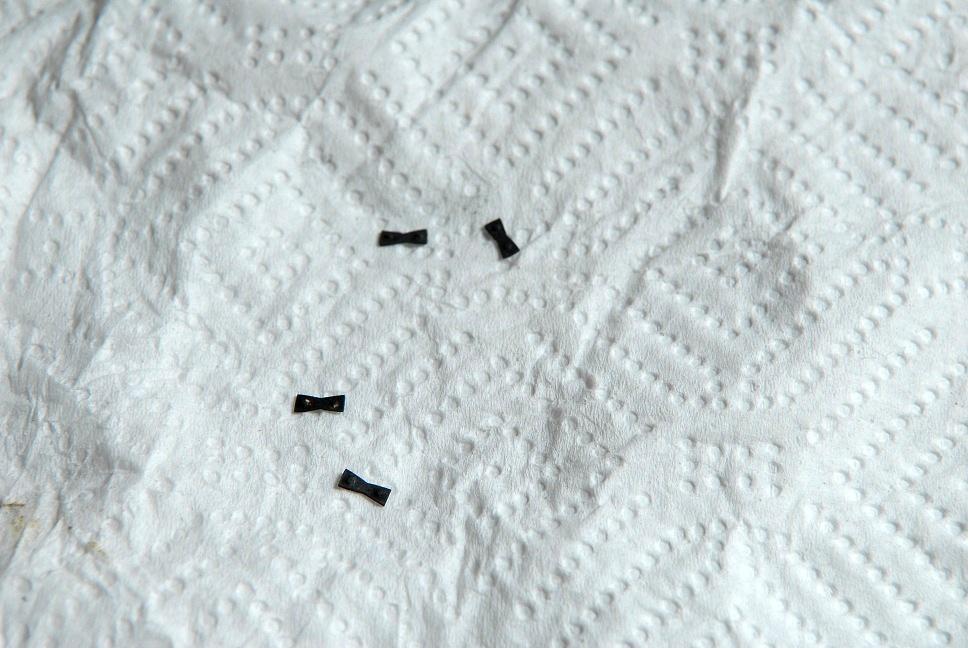
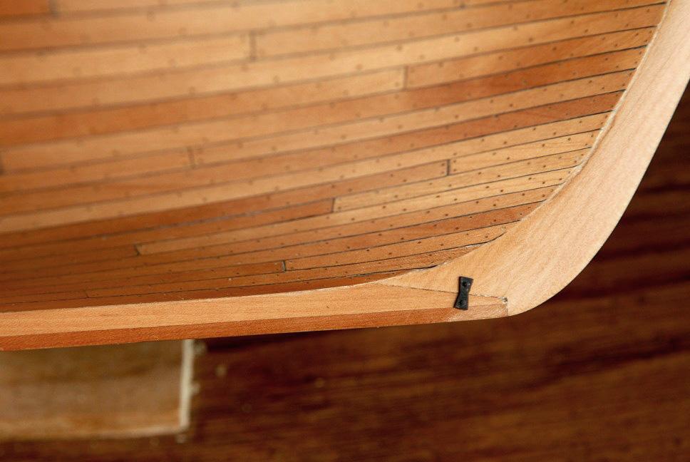
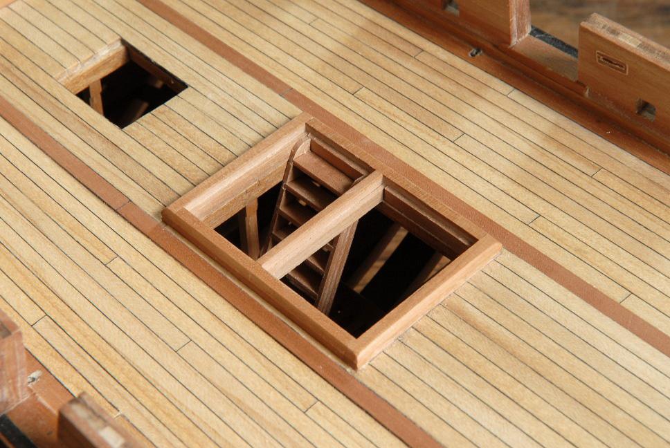
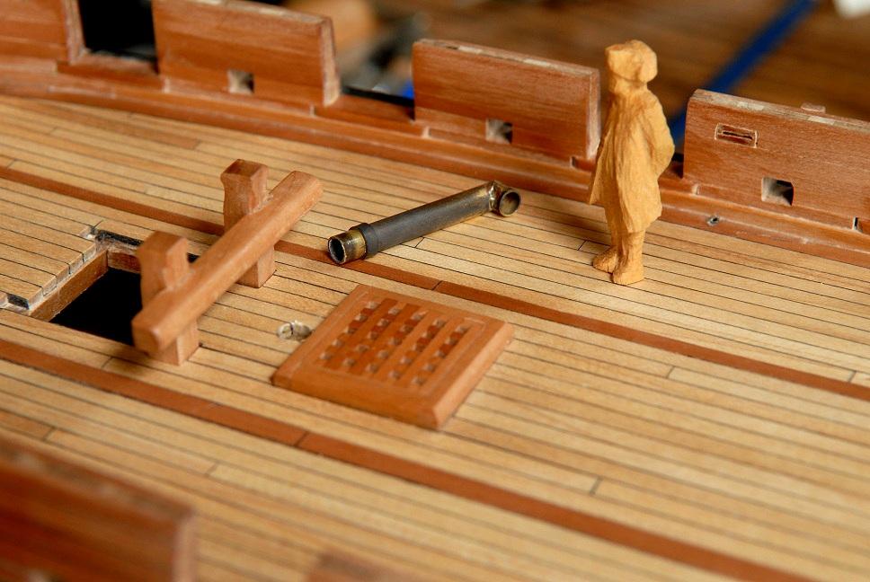
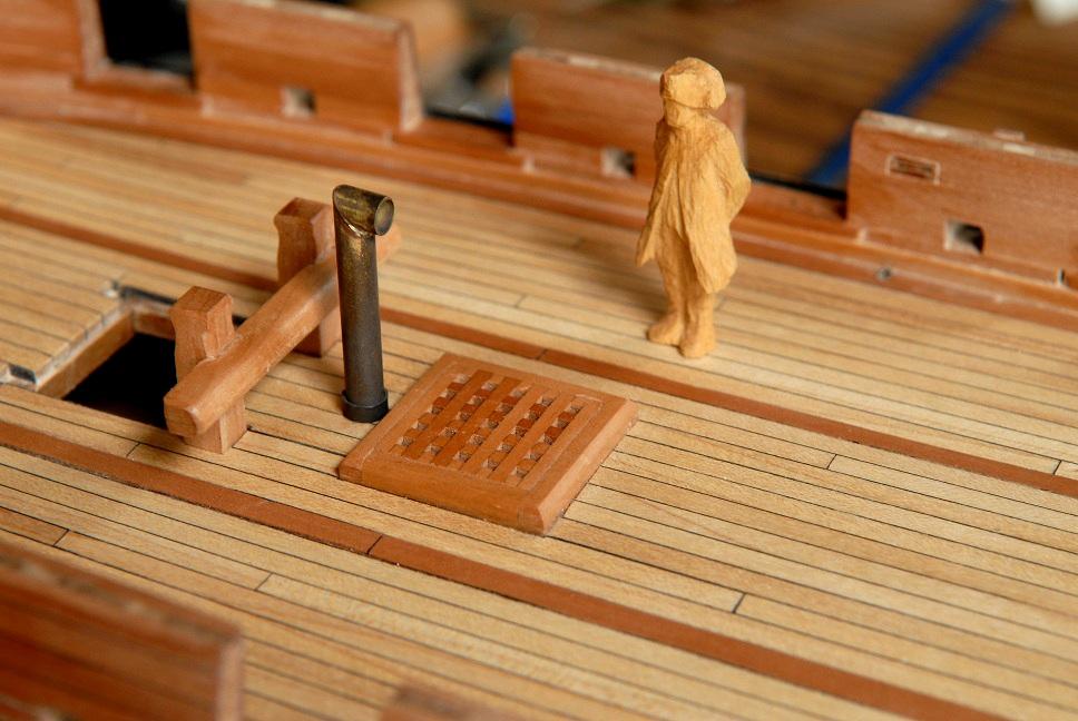
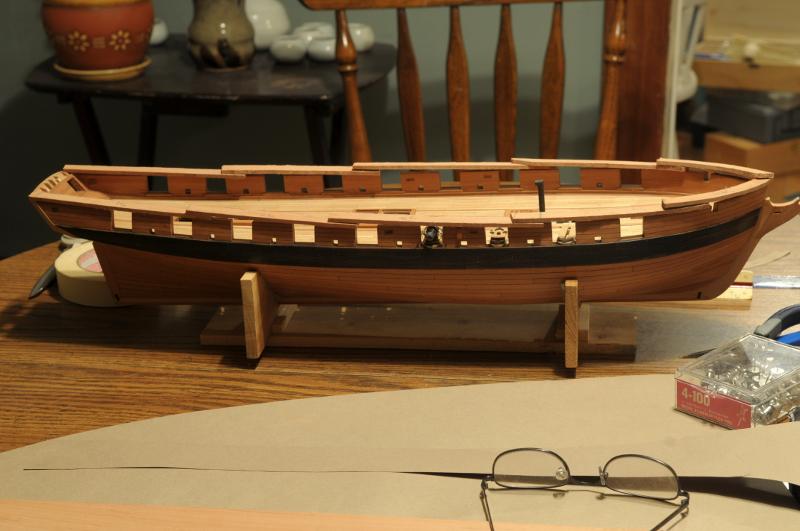
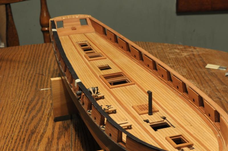
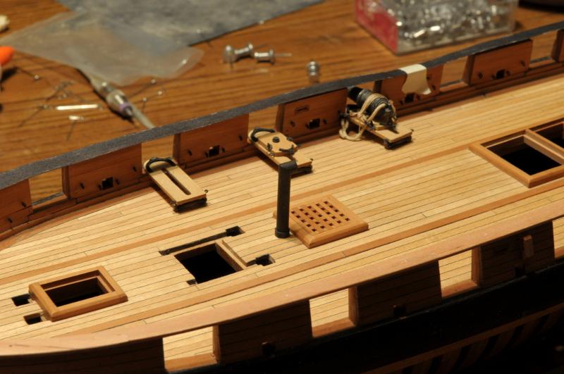
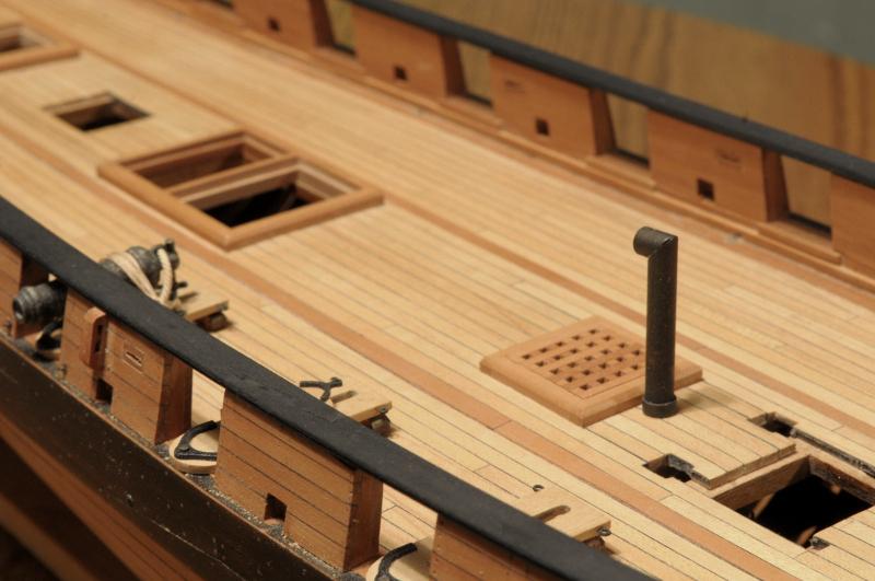
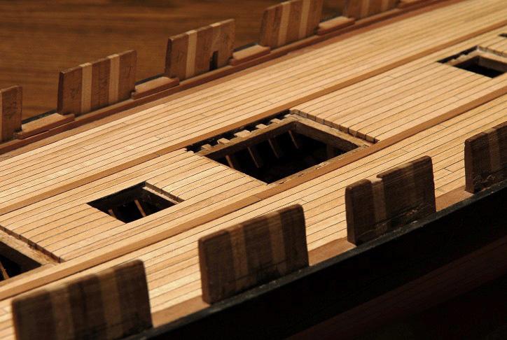
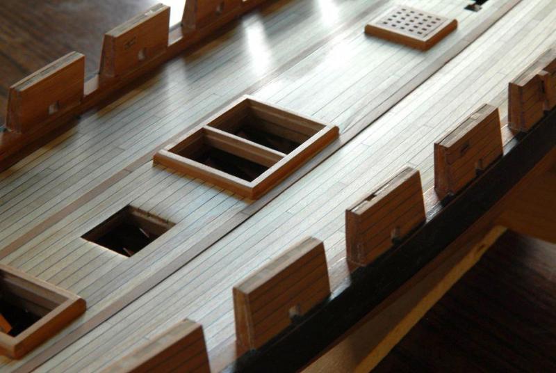
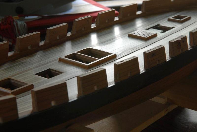
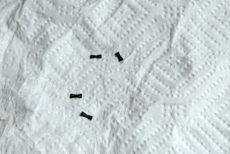
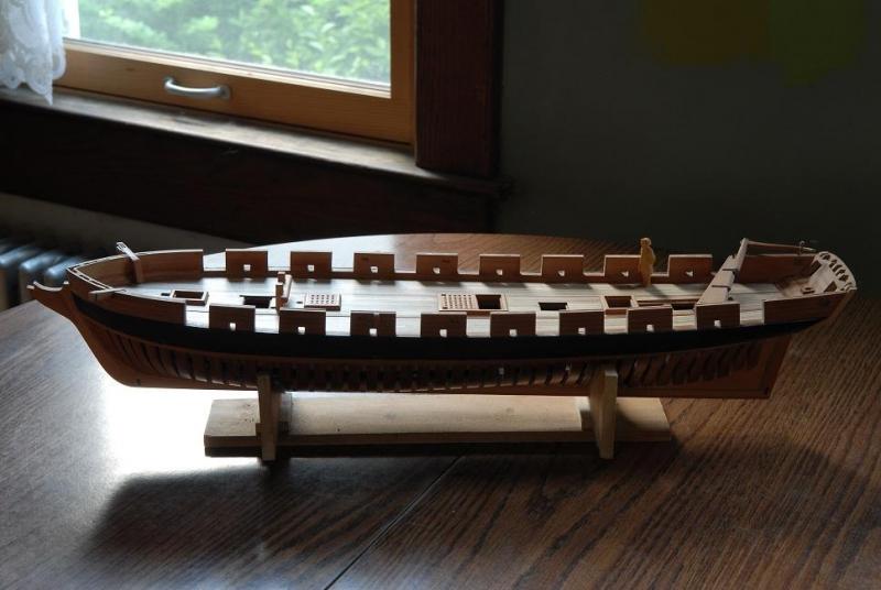
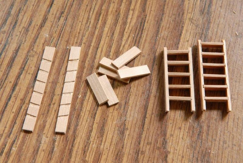
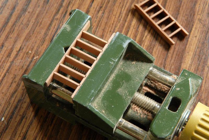
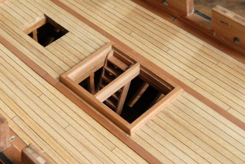
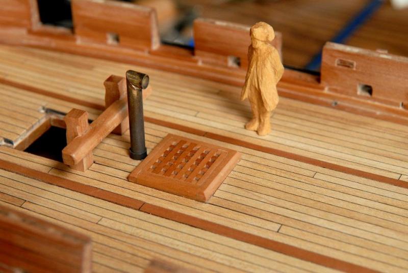
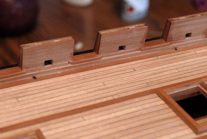
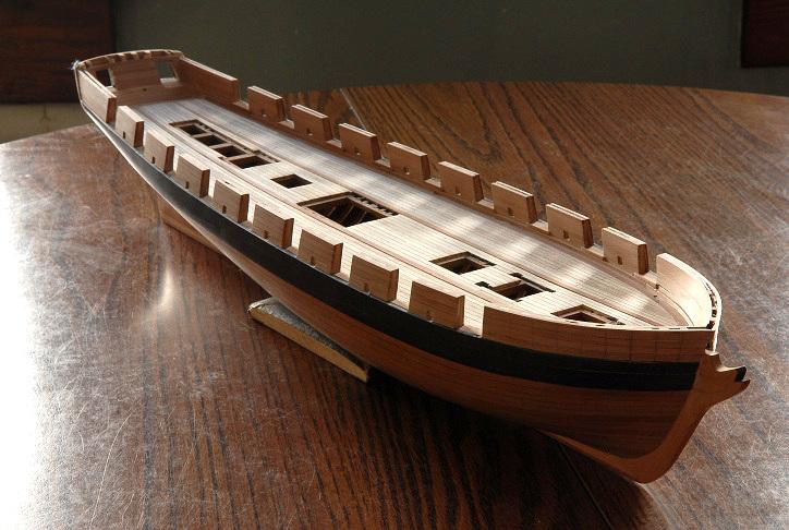
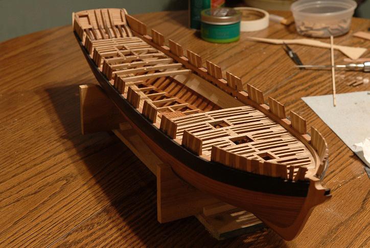
July 2011 Deck Adjustment: A correction to the deck planking was made, after I realized that instead of just the binding strakes sitting proud of the rest of the deck planking, all the planking in-between the binding strakes should also be at the raised height (about an inch). This meant sanding down all the planking outboard of the binding strakes, and sanding the binding strakes down to the level of the center planking. First picture is "before", though it's hard to see that the binding strake is indeed higher than the center planking. It's actually easier to see this on older pictures in the log-- After-- Fishplates: The "bow-tie" shaped iron that helps hold the back-bone together-- You can barely see in this photo, I have also added a "stop-water" dowel at the joint of the keel and stem. I have a stop-water here also, but it's harder to make out-- A nice overall shot of the progress at this point-- Ladders A few ladders were made for the crew to travel between decks. The two on the right are "rejected" first tries-- Like the rudder, these will be glued later. Stove vent Brass tubing was cut, soldered and blackened, though the first blackening wasn't very successful. You'll see better result on that later-- Ron


-
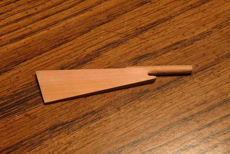
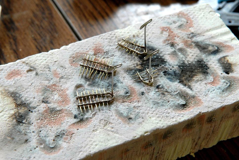
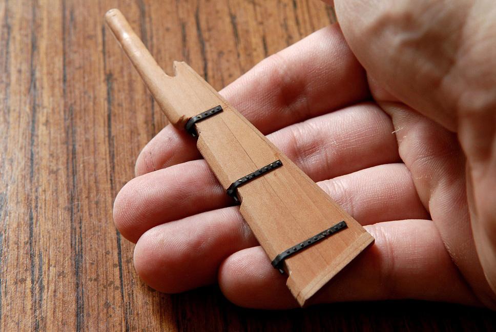
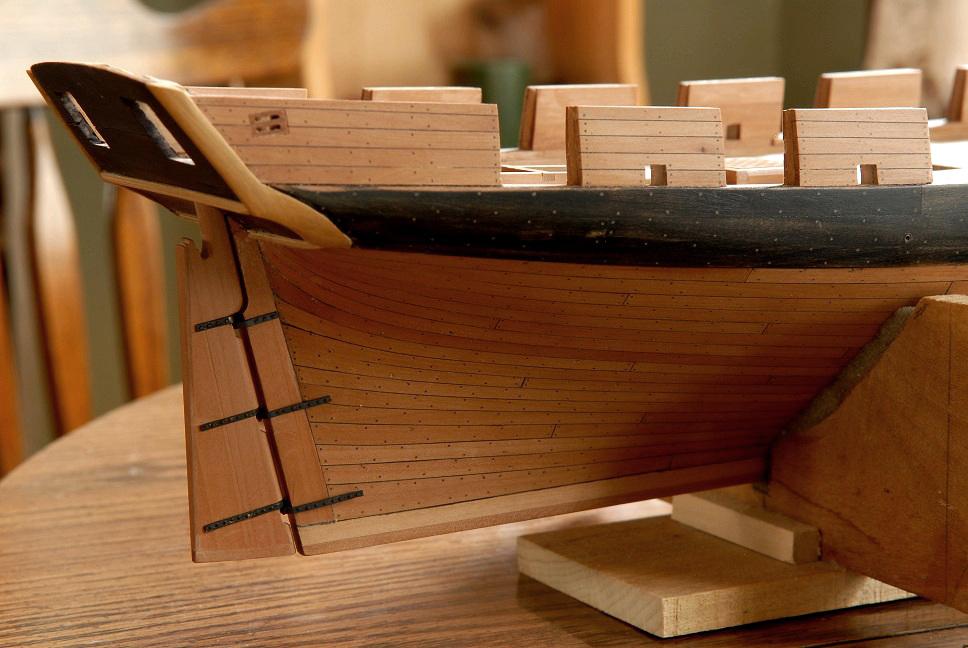
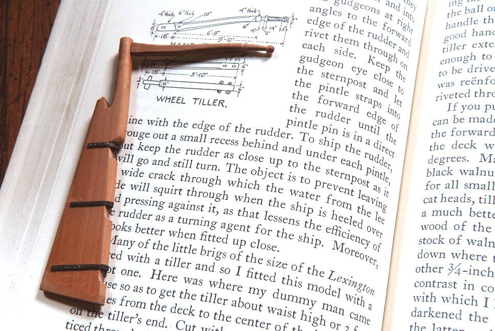
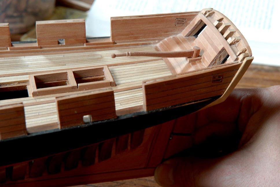
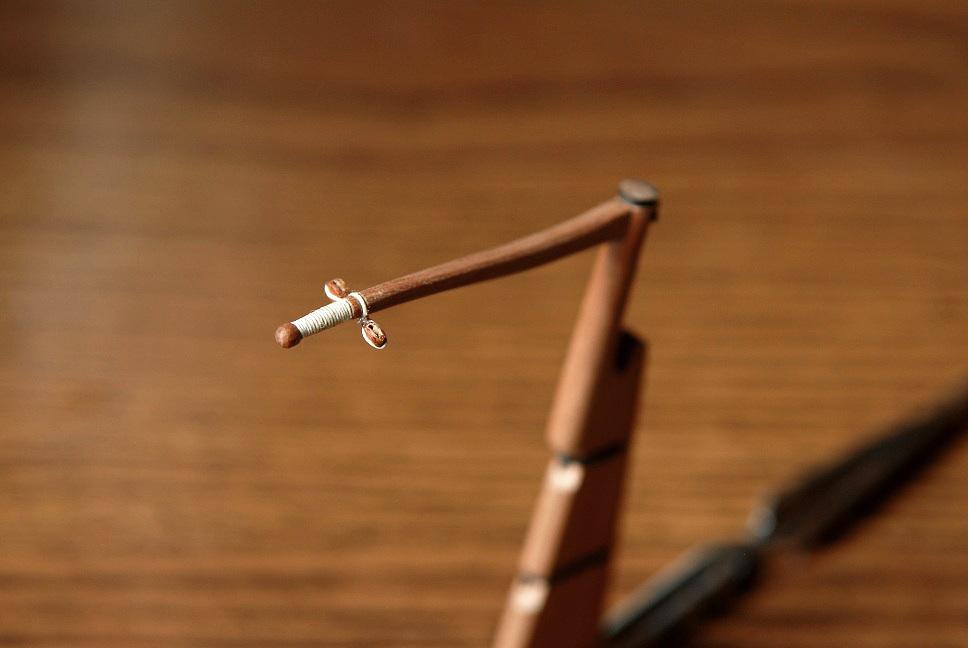
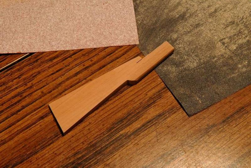
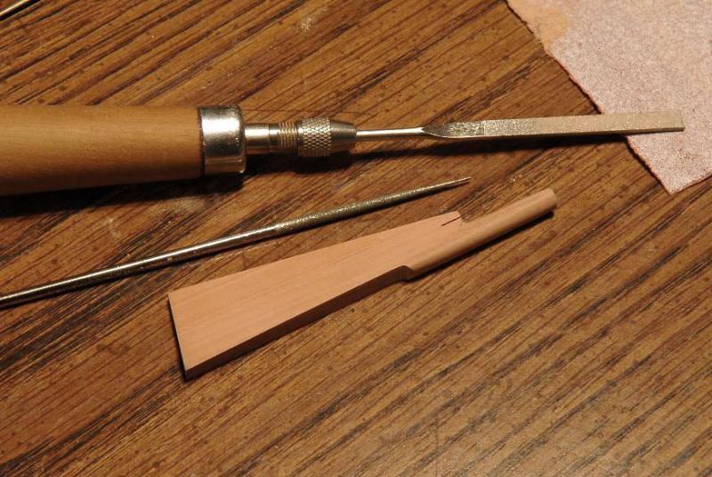
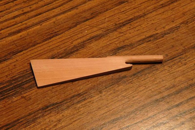
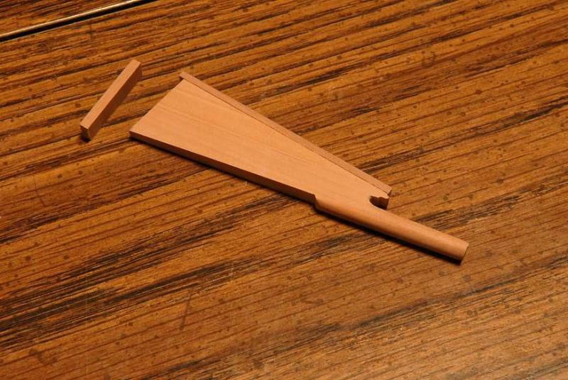
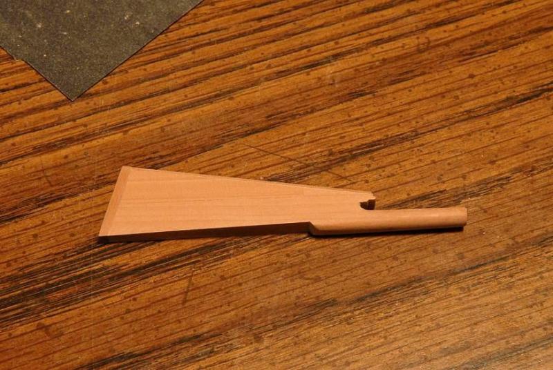
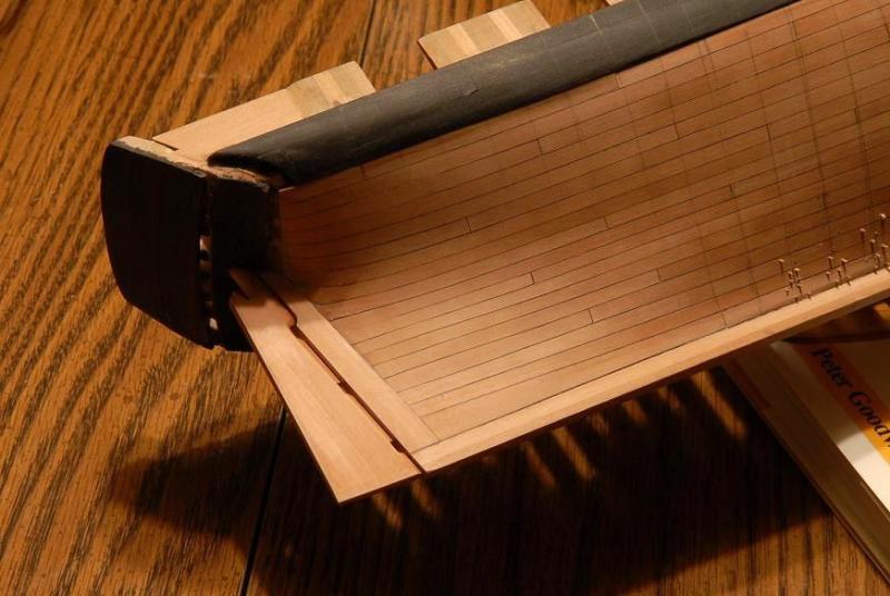
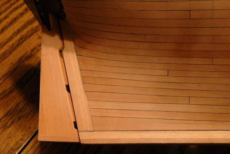
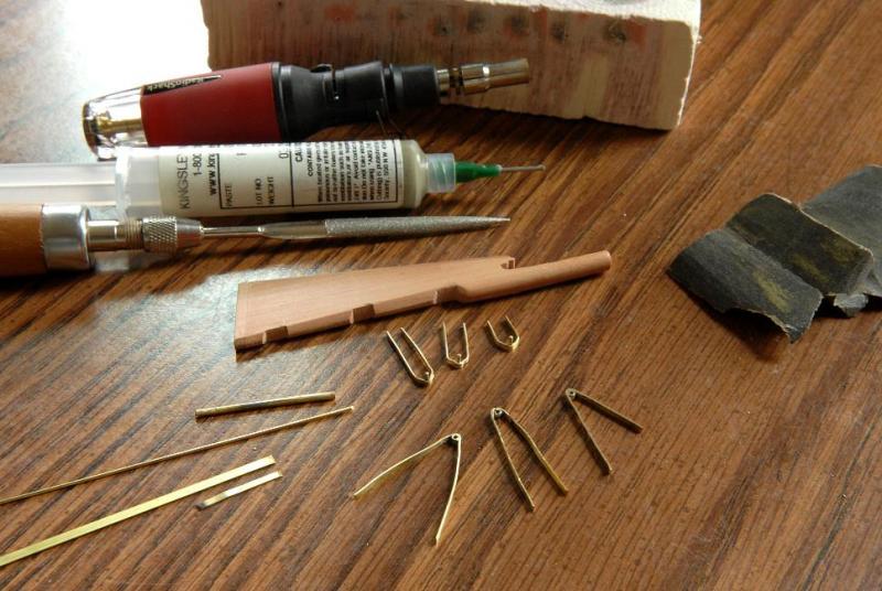
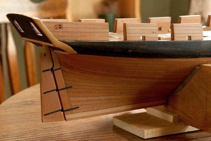
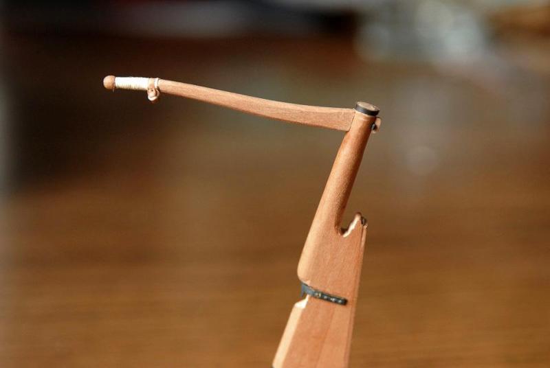
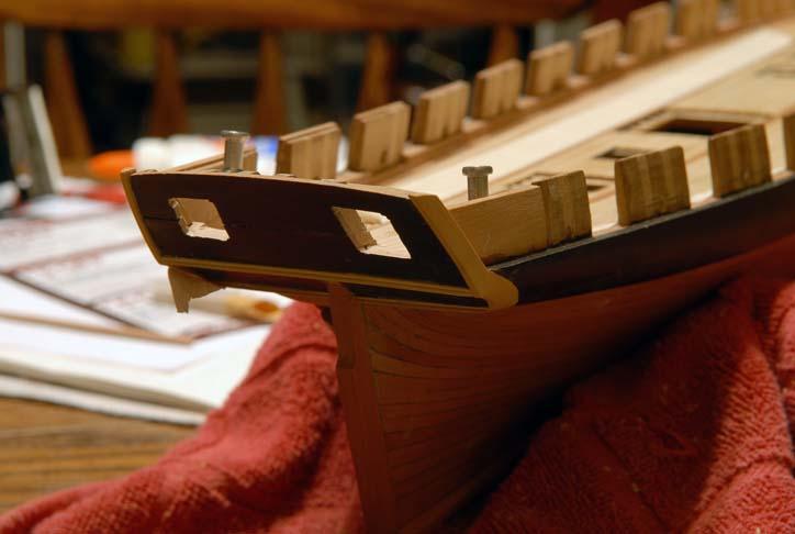
Work on the rudder took place in two sessions. February 2010 Cut-out and shaping-- June 2011 Then fabrication of ironwork and the tiller-- This photo also shows the extra outer sheave that I attached to the catheads at this time-- And my method for making the bolts-- After soldering the wire through both sides, the inside sections is cut away the piece is filed smooth on the inside, and down to just a bolt head on the outside-- Dry-fit to the hull-- The tiller is based on a drawing in Charles G. Davis' book-- A support piece is fashioned at the stern-- Finally, a rope handle and the blocks required for the steering tackle are added-- This will not be glued on to the hull until closer to the end, to avoid possible damage. Ron


-
Thus ends the salvaged log from the old site, my thanks again to Ilhan Gockay! There is still a relatively minor gap from June to August of 2011 (at which point I stopped working on the model until picking up again only days before the great crash of 2013. I have the photos, but not the text, of that period, and I will post those and fill it in with some narrative as best I can. Ron
-
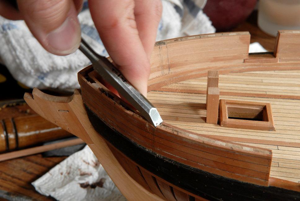
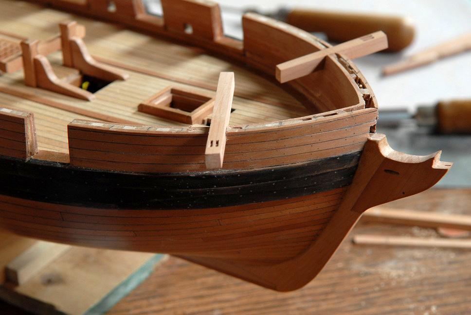
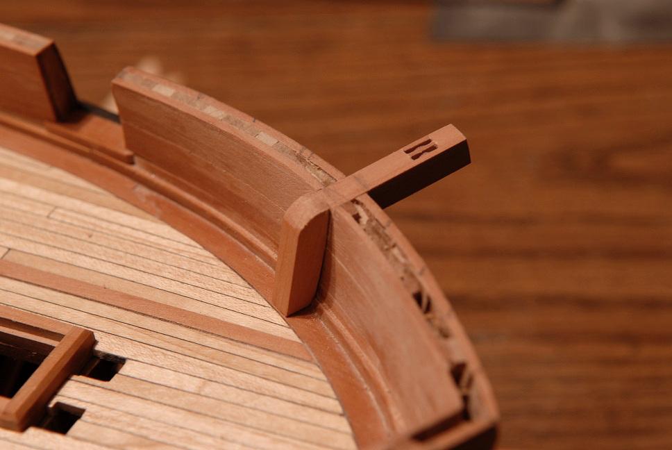
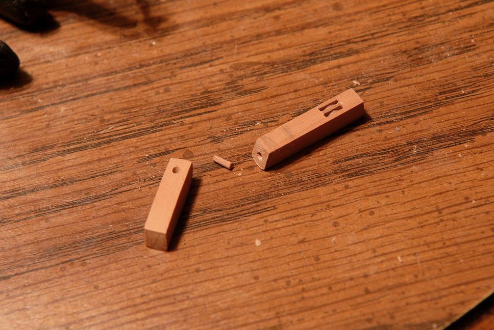
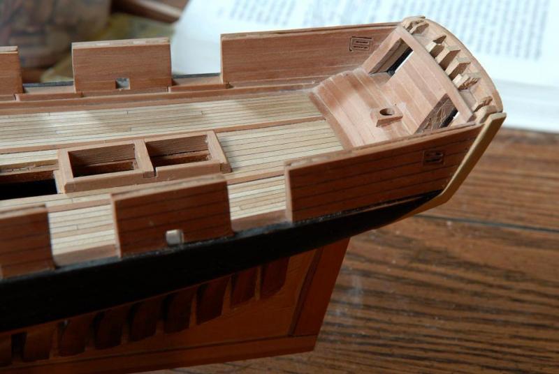
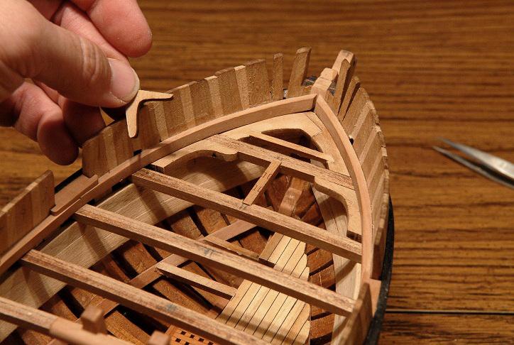
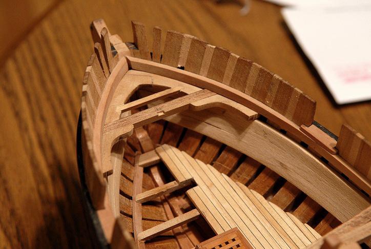
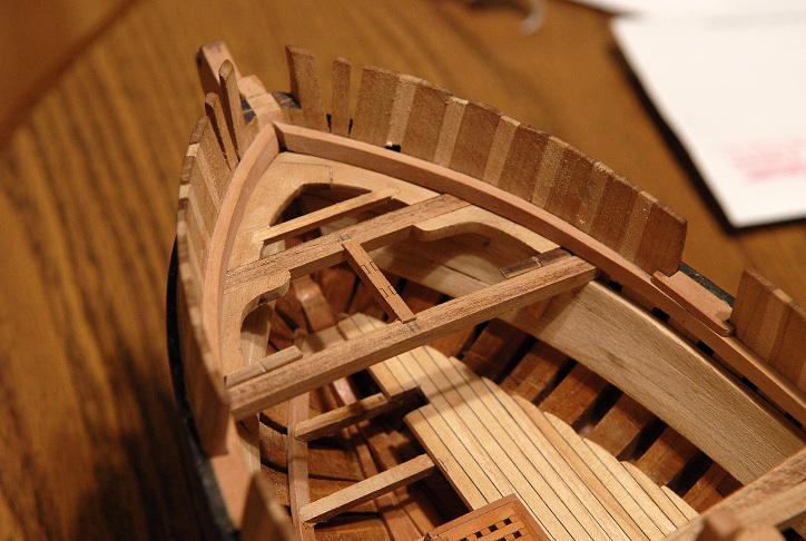
June 19, 1011 Now, more pictures of catheads than you really need---! With experience from the fixed blocks under my belt, I tackled the catheads. The pieces shown below are not cut to length yet. There is extra at the outer (sheave) end, and obviously at the inner ends. I used the same technique as before of gluing up individual pieces, since I don't have the means to cut sheave slots sufficiently narrow-- These sheaves I stained dark-- I needed to be careful of the grain direction in the "layered" pieces. The bulwark blocks shown before contrast a little with the planking , even though they are the same type of wood, because the grain on the blocks was turned 90 degrees from that of the planking. Here I had to make sure the grain that was visible was oriented the same as in the cathead piece-- This picture also shows two additional blocks that will be fastened to outside of the hull near the tack blocks that were shown in an earlier post-- After sanding, the individual pieces blend in well-- June 20, 2011 More cathead pictures: Marked the location of the catheads and cut some slots-- Used chisel and files to cut out the slots-- Test fitting the catheads, making sure the angles are good-- Then I cut the pieces to the right length (except end past the sheaves is still a little long), and notched the waterway-- Then shaped the inner pieces. Technically the catheads should be one piece of compass wood (a piece of lumber that grew naturally with the right bend), but I'm not going that far--the joint will be mostly hidden-- I glued them together with a crude pinned joint-- Here the joints are being glued together with the catheads temporarily in place, to help set the right angles for the joints-- Now they can be removed, and finished-- Ron


-
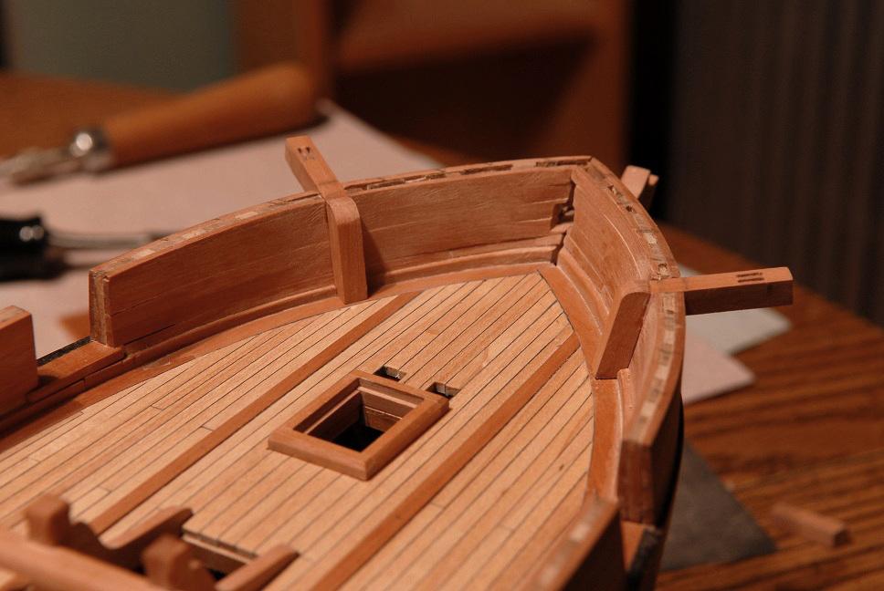
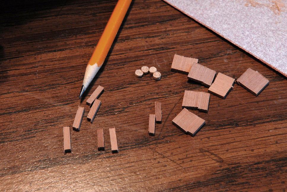
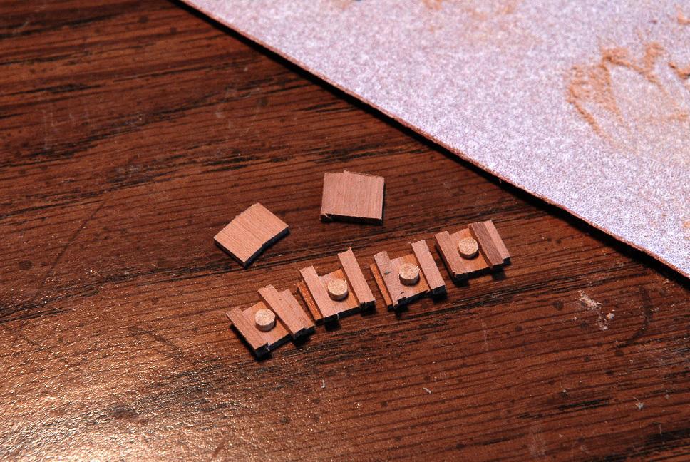
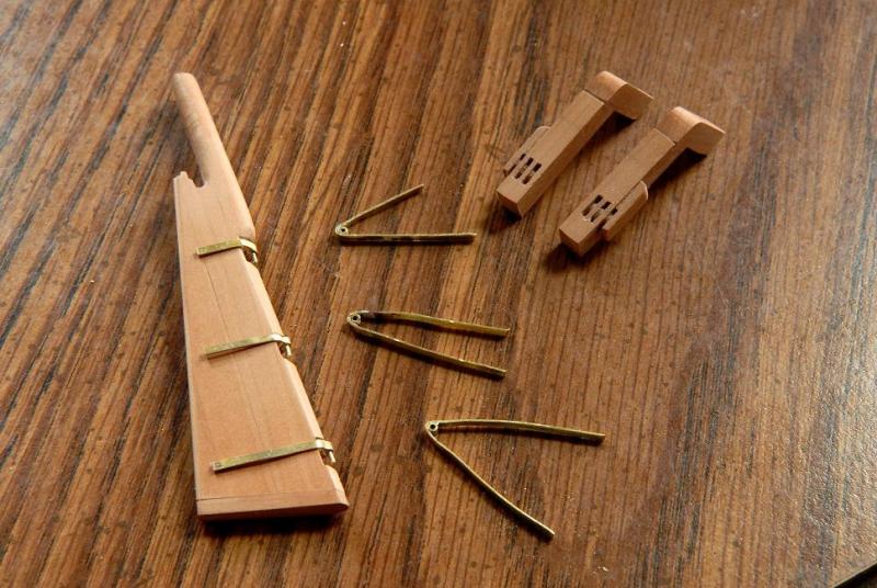
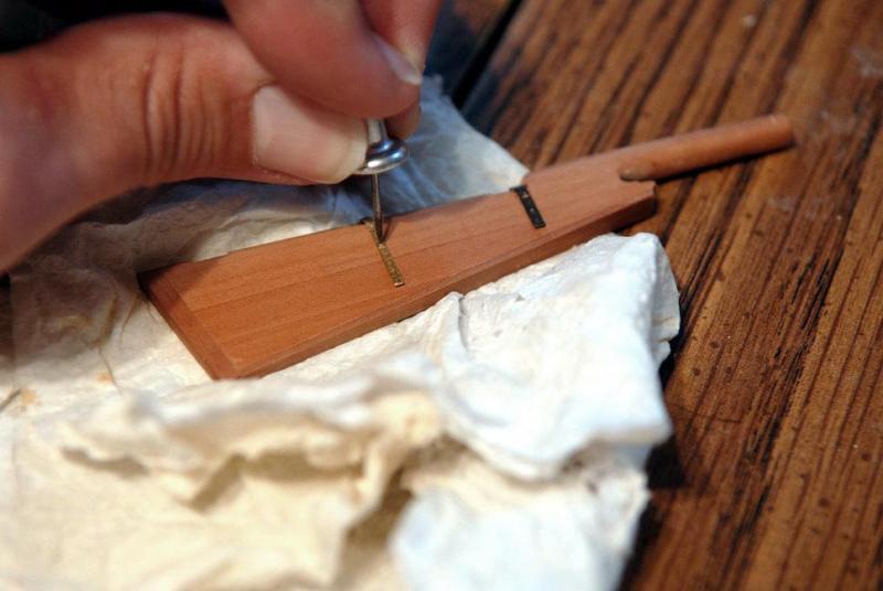
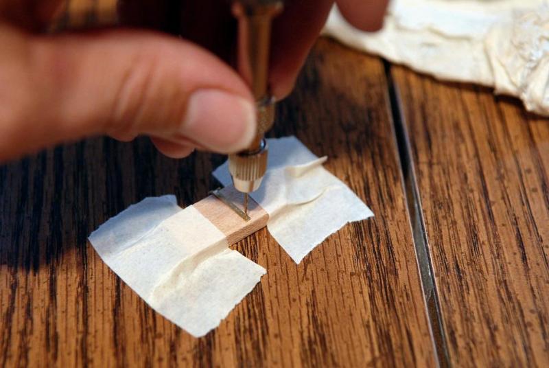
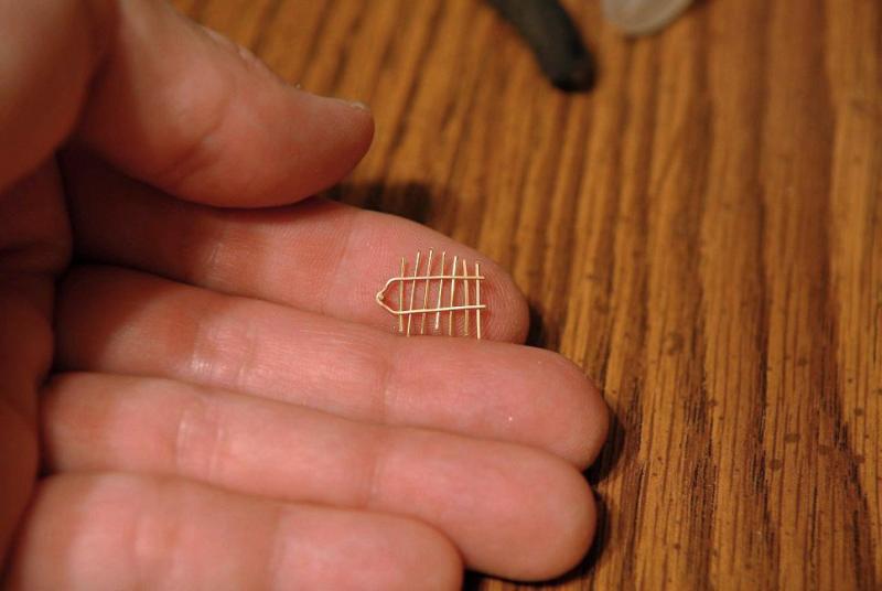
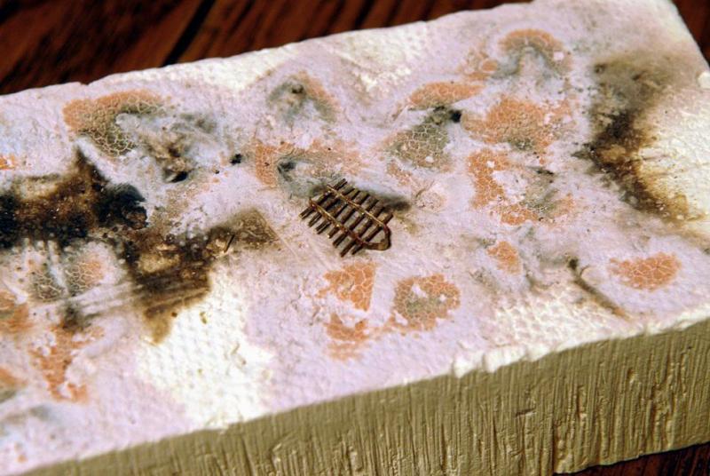
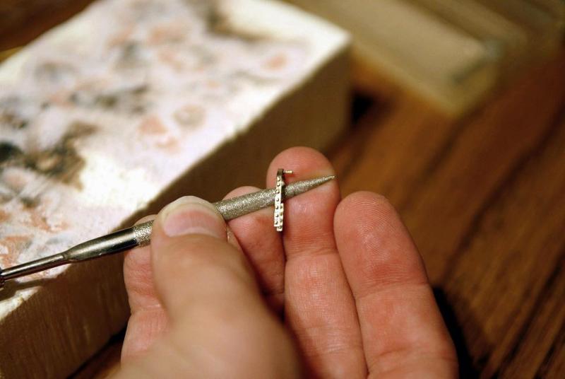
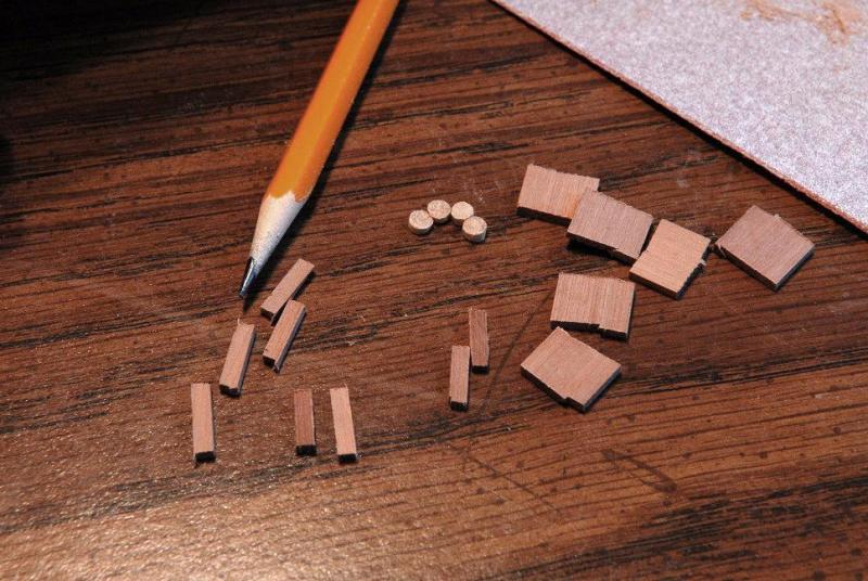
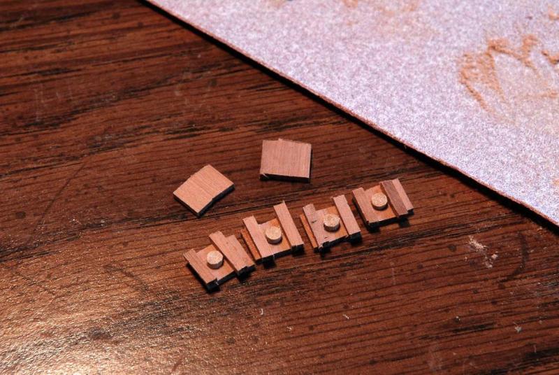
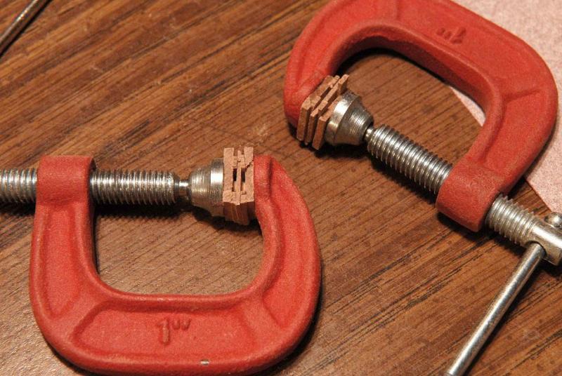
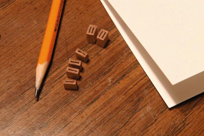
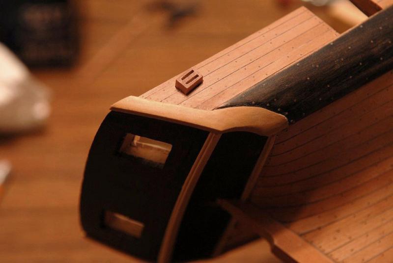
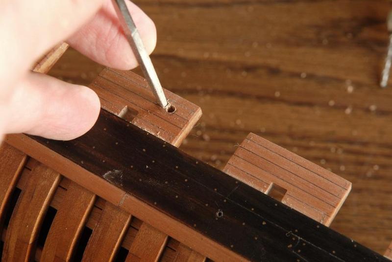
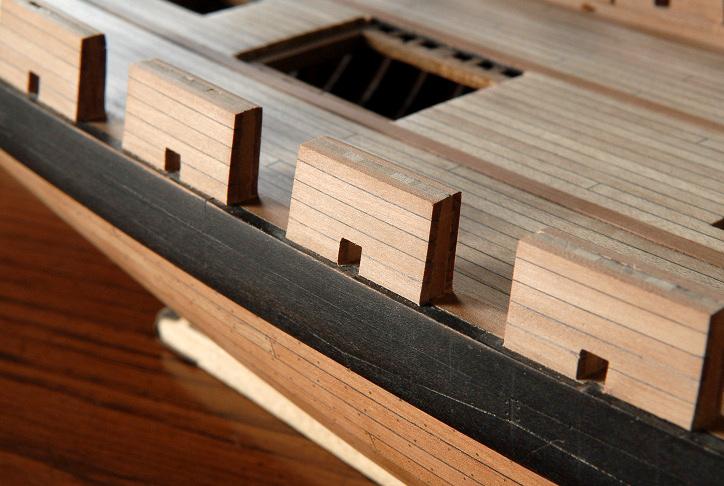
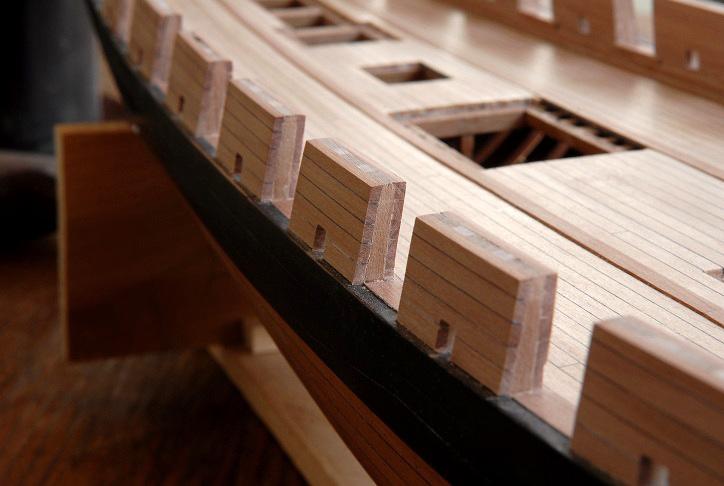
June 14, 2011 Next task was making the fixed blocks that are inserted into the bulwarks for the rigging. I determined that I need six of these, with the aft ones being double. One sheave for the main brace and one for the main sheet. Farther forward are two (port and starboard) single blocks for the fore sheets, and forward of that is a pair for the main tack. Here are the pieces needed for the two double blocks. I don't have a thickness sander, and my stock for making these is not the right thickness, but it didn't matter, only the diameter of the sheaves had to be right--and that was a guess on my part based mostly on the thickness of the bulwarks-- First the sheaves and ends of the blocks had to be glued to one of the side pieces-- These were then sanded down to their correct thickness, and the center piece that separates the two sheaves in the block was glued on-- The center piece was again sanded down to correct thickness, and the outer side was glued on-- Here's a comparison between the rough glued up block, and one that has now been sanded down to size-- Here are the six blocks, sanded to roughly their final size except for the depth. That will be sanded down after they are glued in place-- Next was cutting a hole in the bulwarks. This was done by drilling a starter hole, then slowly enlarging it with files-- Test fitting the block-- And finally gluing it, sanding it down flush to the planking, and giving it a quick coat of finish, just to see how it looks-- Five more to do! June 18, 2011 Hello fellow modelers--I've finished the bulwark blocks. Some pictures of the procedure for the single blocks on the port side-- Here they are glued in. This shows the amount of extra depth I built in to the blocks--not a whole lot! It's about the same on the inner side-- Sanding with a nail file, then 250 paper, and finally 600-- Here's a shot across the deck, you can see the inner side of the corresponding blocks on the starboard side. I'm still not sure I'm okay with the light wood I used for the sheaves. I may try darkening the sheave on the outside of one of the tack blocks (the least visible of them all when all is done) to see if that looks better-- Overall. I've glued in some of the hatch coamings, still have work to do on the bowsprit step/seat. That will wait until I actually begin making the bowsprit-- Pondering what to tackle next--probably the catheads. Ron


-
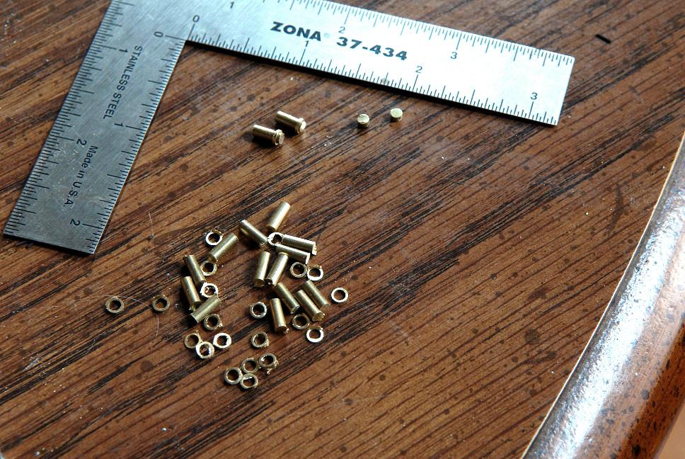
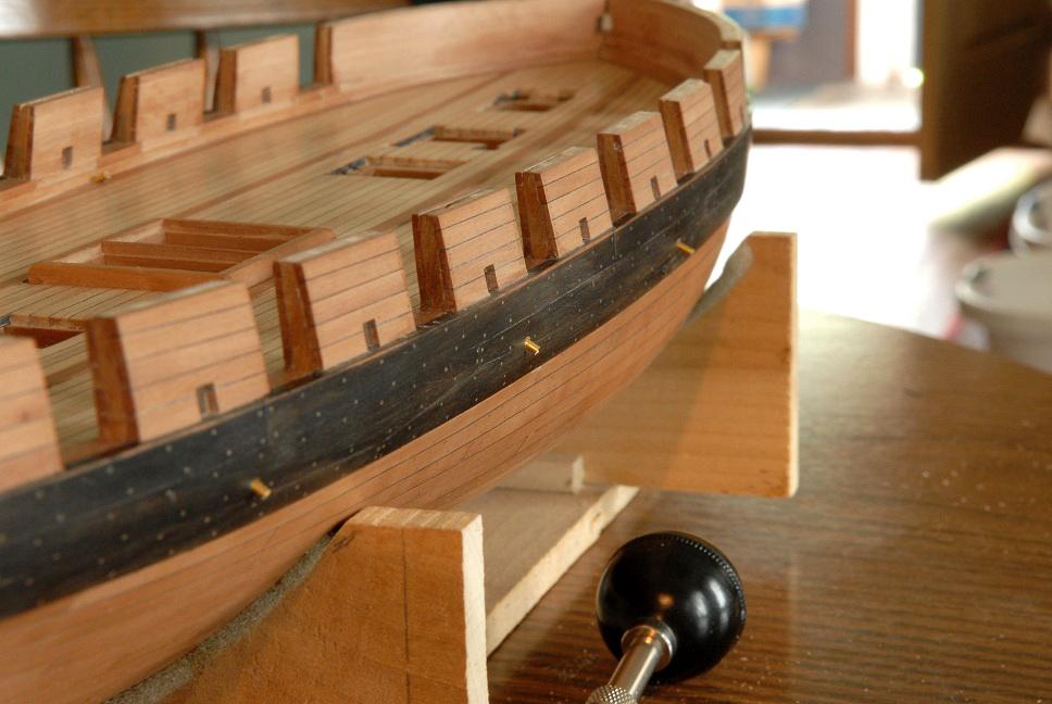
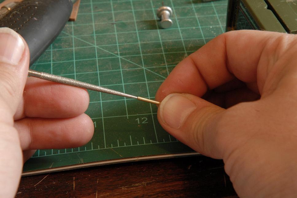
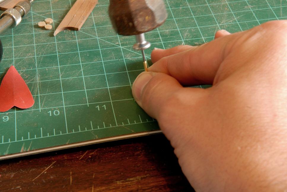
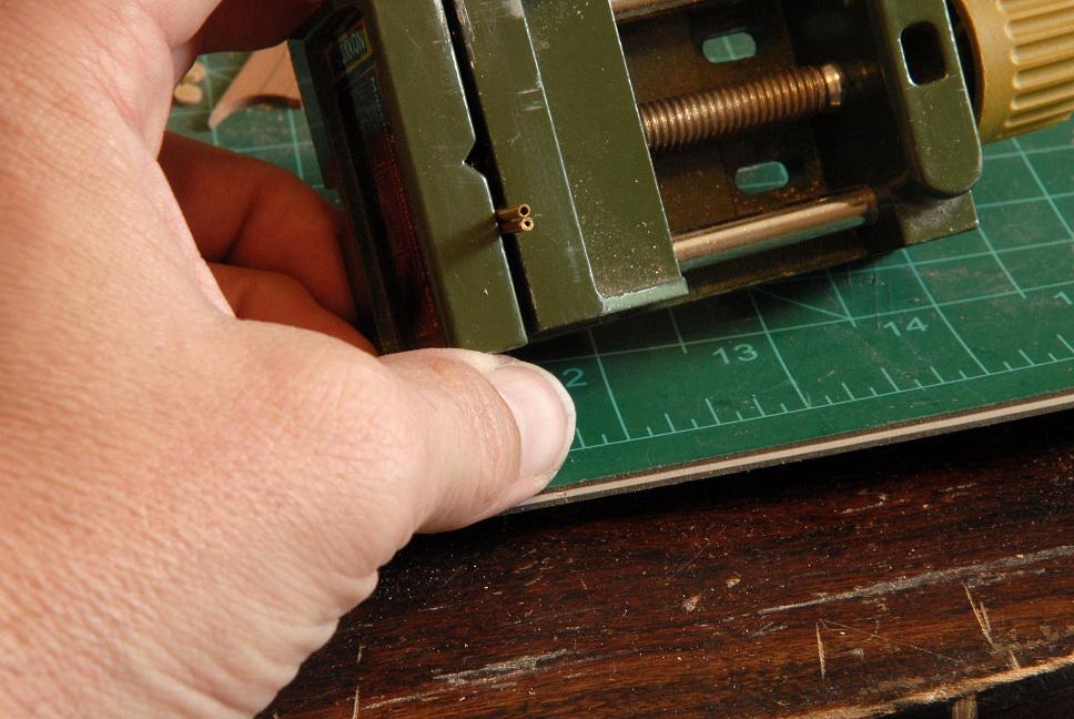
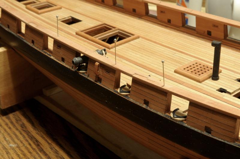
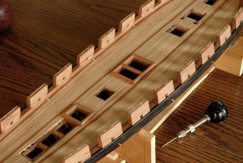
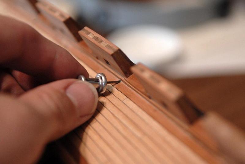
June 5, 2011 It feels like ages since the last update. [Ha, well, not really in the reposting. In fact, I am getting kind of sick of looking at my Oneida photos. But the reposting is almost done!] I have finished treenailing and sanding the bulwarks and wales. Next I installed 6 scuppers. After studying what little information I had available, I located three scuppers on each side. One at the lowest point of the deck sheer, and two others equidistant from the one at the low point. Then I drilled through by hand, a little bit at a time from marks on each side, judging the angle by eye-- Finally going all the way through-- My first thought was to use a single piece of brass tubing for each scupper--here they are pushed through the holes-- I filed the center hole a little to widen the inner diameter-- Realized that a faster way would be to hammer a pin into the end-- This shows the difference between a freshly cut end, and one that has had the pin hammered in the end-- I also quickly realized it would be too difficult to get the right angles filed on the ends, as well as the correct length at the same time, so I cut each tube in half and fabricated the ends separately. I used the same pin to hold the pieces for test fitting. (The test fitting actually happens before the piece is blackened) -- And gluing them into place with CA glue-- At both ends of the photo you see two of the scuppers-- And also on the outside-- Contemplating what do do next. The cap rails will wait for a while. There are blocks to inset into the bulwarks, eyebolts for the carronades, the catheads and some other things that I think will be better to do before the cap rails. All for now, Ron


-
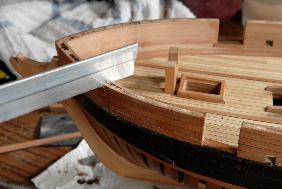
Thanks, Russ. I can't remember where I got the jeweler's saw. I don't think it was from Model Expo or Micro-mark, but it wasn't an expensive one, maybe one step up from the least expensive ones. And I do break a lot of blades. I just recently learned that it's best to put the blade in so that it cuts on the up stroke (if you're holding the handle up as in my photo), so that you keep tension on the blade during the cutting stroke. Ron
-
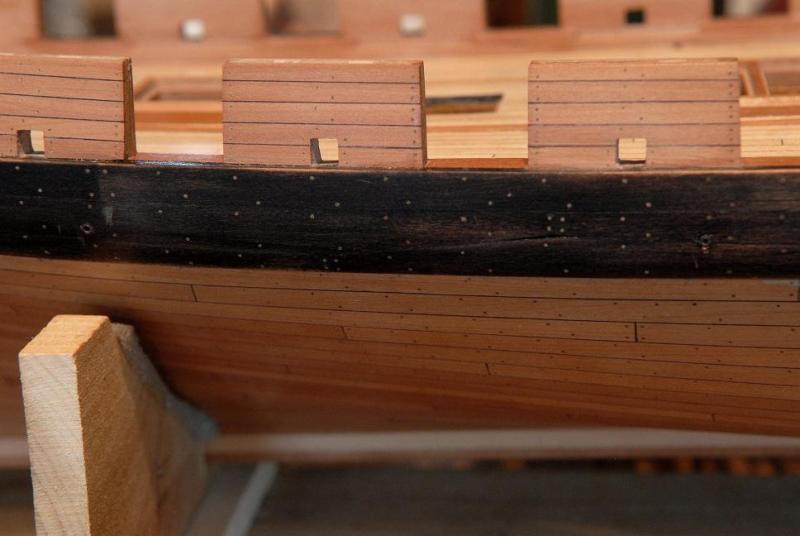
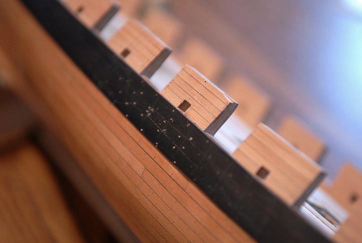
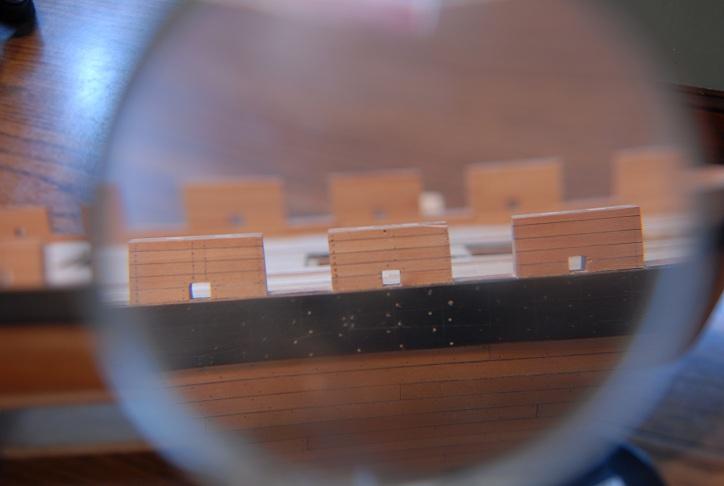
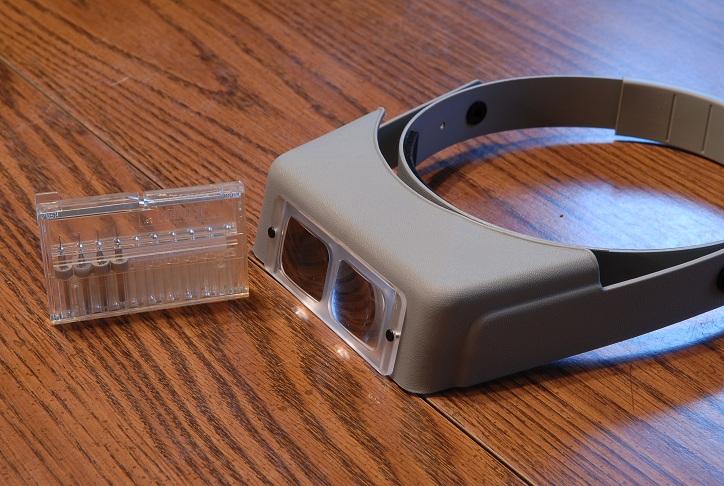
March 29, 2011 The sweep ports have been filed to size, and the bulwarks have been sanded down to the correct height-- I've started marking the bow bulwarks with guidelines for treenails-- Hard to believe I'm approaching the end of the framing and planking (also hard to believe it won't be long before I reach the two year mark on the build!!!)-- Still treenailing to do, and the top rails; but I'm mentally gearing up for the next major phase--a multitude of little constructions--capstan, pumps, finishing the rudder, to name just a few--to complete the deck and hull. I have to get back to planning the rigging, so I know where to put cleats, sheaves in the bulwarks, etc. April 7, 2011 Working on thinning the bulwarks. Here is the starboard side which hasn't been done yet-- Compare that to the port side which has been sanded so the tops are 9.5 inches wide-- The difference is not huge, but it's definitely noticable, and the thinner ones look more correct-- April 15, 2011 My next task was to drill the necessary holes in the stem for the gammoning and bobstays. Using the Bergh hull plans and sail plan as a reference, I started drawing in pencil on the stem, and became aware that the porportions were a little different. The stem I had was almost 1/4" (a foot in scale) shorter than the one on the plans. [i'm not sure what happened here, but I think part of it is that my rabbet may have been cut too far forward.] After thinking this over for quite a while (while sanding the bulwarks down) I resolved to replace the stem piece. This would also make it easier to drill those rigging holes. I traced the profile from the plans, and cut out a new piece-- Here's a shot that shows the difference between my earlier stem and the one based on the plans -- Using isopropyl alcohol and some care, the old one is removed-- Test fitting the new piece-- The gammoning slot was made by drilling 4 or five holes in a row, threading the jewelers saw blade through the last hole and sawing from one end to the other. This was the only way I could think of to clean up the slot--a sliver of sandpaper-- Here's the new stem piece glued on-- After this dries, there are some areas I need to file and sand to meet the stem just a little better-- April 21, 2011 Woolsey on deck-- May 4, 2011 Friends, After the fix of the stem, I turned to the task of treenailing the wale and bulwarks. I was quickly stopped short. In a span of minutes I broke 4 of my .020" drill bits. I drilled the treenail holes for the complete hull planking without breaking a single bit. (Actually, I did break one, but it was not while drilling--I carelessly let the bit contact the table while setting the drill down.) So this really took the wind out of my sails. I managed only a very small portion of the wale and one section of bulwark. The picture shows bamboo treenails glued into most of the holes that I did successfully drill-- I also found it very hard to see what I was doing. My vision has been great until the past year, but age is catching up with me and I've noticed a dramatic loss in my close up vision. I was trying to rig a magnifying glass to help me, but I think this contributed to my poor handling of the drill. This is what you see through the magnifying glass. A mess. I broke the top corner of the bulwark by pushing a little to hard with the pin I use to make a starter hole for the drill. One of the empty holes has a drill bit stuck in it that I don't know how to remove. Another hole was double drilled. It's hard to look at this and not get discouraged-- Fortunately, I've been doing this just long enough to know that it's going to come out okay in the end. I ordered some vision help [i am kicking myself for not getting one of these sooner. I can actually see what I'm doing now!! Sometimes it seemed like I was working by feel as much as sight.] , and you see my remaining supply of bits (plus one that is in the drill)-- And I'm ready to go again-- May 12, 2011 Just a small update--I have drilled and glued the treenails in the starboard wale and bulwarks. Both are .020". And no more drill bits broken! They have been sanded flush, but still some final sanding to do-- After some more sanding, and a coat of finish-- It's interesting to me that the exact same bamboo treenails look like black spots in the wood of the hull and bulwarks, and light spots in the stained wale. I'm glad--I was afraid that they'd disappear completely in the wale. [i unfortunately lost these in my recent modification of the wale. The treenails got stained black, so they are not visible anymore] Also, there are places where I sanded partially through the black stain. I'm not sure whether I like the way it looks, or whether I'll somehow try to fix those areas. May 16, 2100 Treenailing continues on the port side-- Ron


-
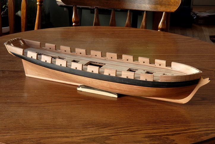
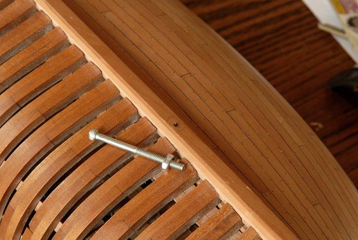
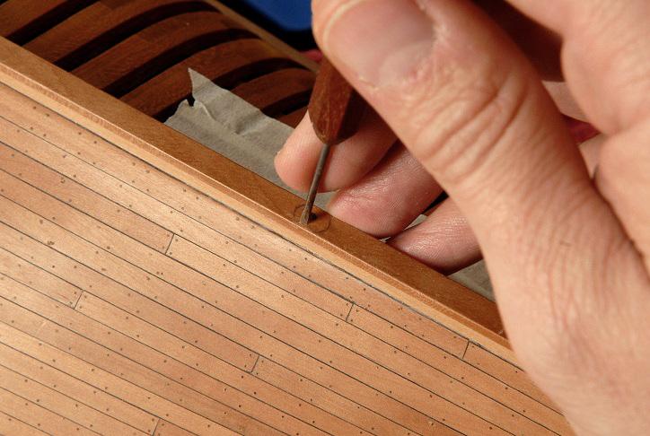
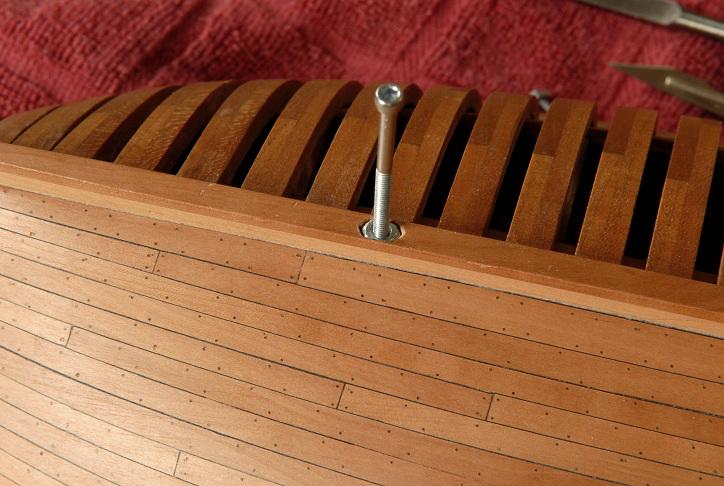
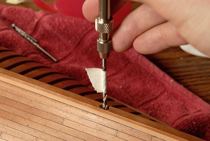
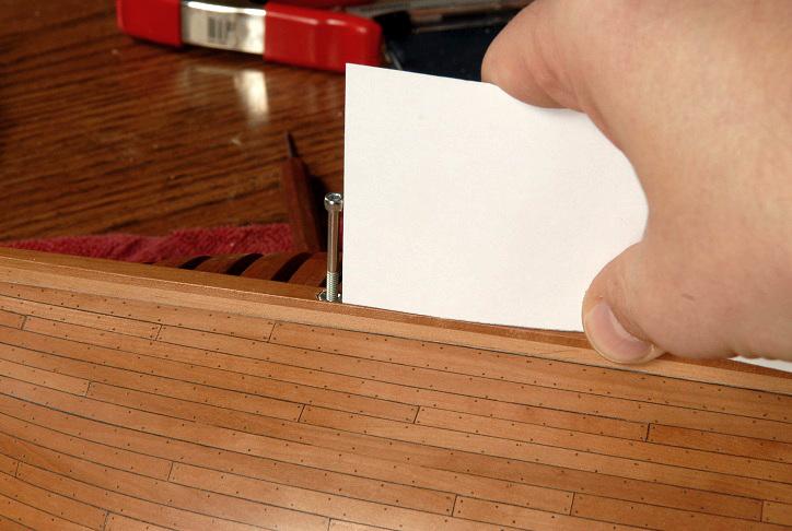
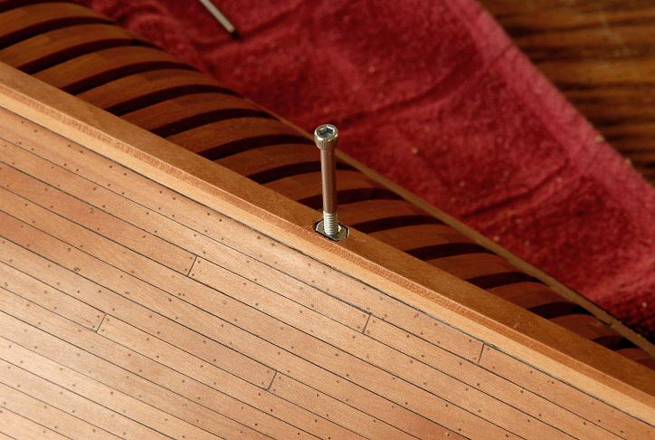
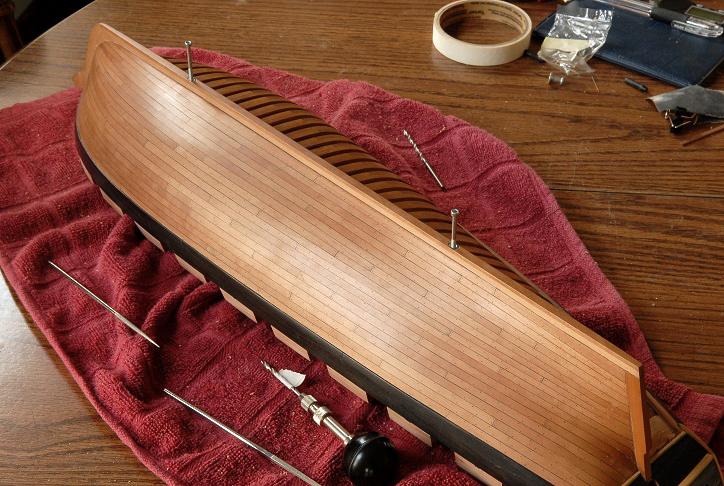
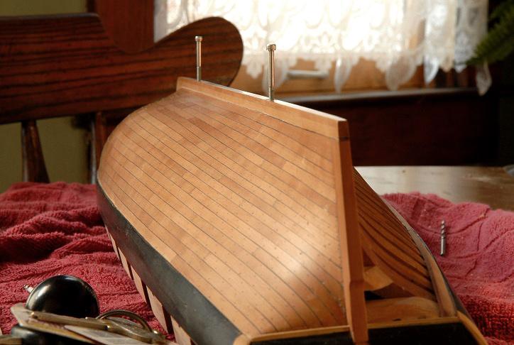
March 19, 2011 Here is how I am planning on attaching anchor bolts for the display base. But before getting into it I'll just explain--it would have been better to sandwich the nuts between the keel and keelson, or the keel and a frame floor, but at the time I was gluing the keel together, and the frames, I felt too insecure about exactly how to do that. Part of it was that I wasn't at all sure about where they should be located on the keel, to achieve a nice balanced spacing. So, I rather foolishly blew on by that step. Now, the attachment will be a little less secure, and possibly prone to ripping out, but if the model is in a case, I think this will still be one step better than just resting on supports with no mechanical attachment. First I filed the sides off of two nuts, so that they would fit inside the width of the keel-- Here is the filed nut sitting on the keel-- I traced around it and carefully carved out a cavity for the nut-- The cavity is just a hair deeper than the nut-- After I was satisfied with the depth of the cavities, I drilled into the center, to allow the bolt threads to go further into the keel, to give some additional sideways resistance--in other words that should help keep the nut from ripping out of the keel if the model is accidentally pushed or rotated sideways-- There is a slight "drag" to the keel. It is not parallel to the waterline, so that necessitates that the angle of the supports be slightly off 90 degrees. I transferred the correct angle to some card, and checked to make sure the bolts were close to this angle. It's barely visible, and there is some play in the dry fitting. When gluing the nuts in, I'll have to watch this carefully-- Here is the bolt screwed down into the keel (compare it with photo just before the drill bit picture)-- And here's a shot of the two bolts-- The perspective fools the eye, but you can see that more threads are showing on the bolt in the background, this will bring the bow up farther than the stern, and result in the waterline of the model being parallel to the base, rather than the keel-- Ron


-
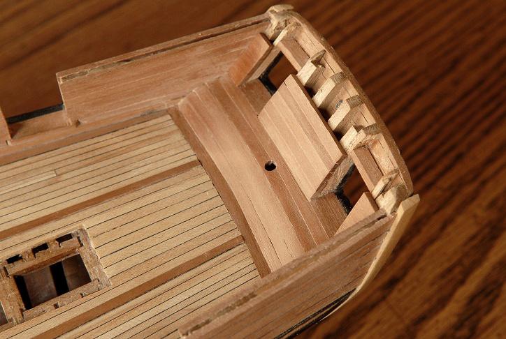
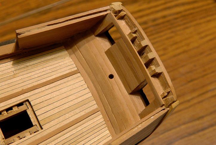
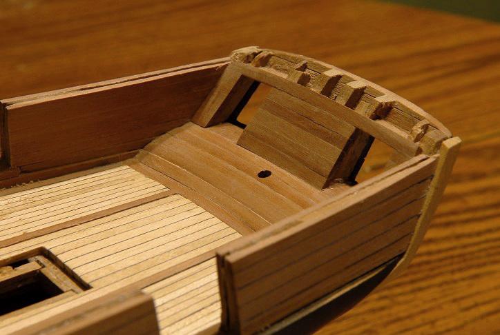
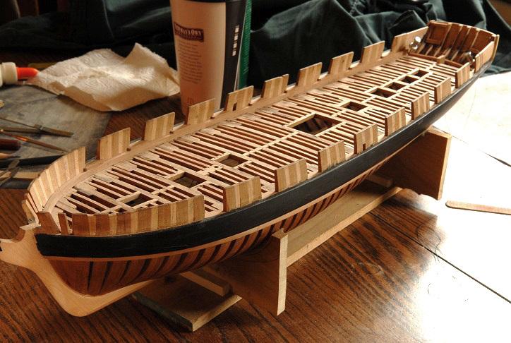
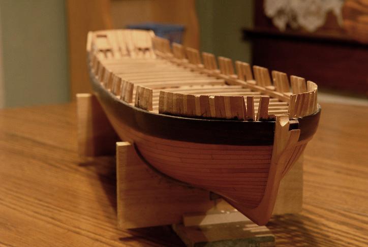
March 12, 2011 Bulwarks are all planked. They still need some sanding, fine tune the height, and file the sweep ports to the proper size-- To finish planking the transom is next-- March 13, 2011 Fortunately I was able to make the bow problem go away! Now, I have to make a stern problem go away. I have been dreading finishing up this part, but as always, just taking things one step at a time keeps what seems like a complicated task from being overwhelming. I had reshaped the transom ports from what was framed by the timbers, and as the inside planking approached the ports, I needed to resolve this mess. First, I realized that to get a good joint between the planking and the port sills, I would need to bring the planking up one more piece, and then make new sills to fill the gap. Here the last bit of the starboard side sill is cut away-- Then glue the next piece of planking. The rudderpost hole is just a starter, it will be sized to the rudder later-- Then I made the new sills, this time out of pear, which will match the others, and the planking. Also, I blackened the edges of the outer planking-- Then I glued some scraps of cherry for the missing jamb pieces. The more "true" fix would have meant completely dismantling the transom, and reframing the transom timbers; definitely NOT something I was prepared to do!-- Last was gluing in some new lintel pieces-- And now I'm ready to finish planking. One tricky thing here is that to get the shallow edge bent curve of the planking I think I'll have to boil some long pieces, and after setting a curve in them, cut them to the shorter lengths needed. March 15, 2011 Here is a small supply of slightly curved planks. I did run out of this size--these were sanded down from wider stock-- Planking continues up the transom-- February 18, 2011 I now started planking the narrow areas on the two sides of the transom. I cut a small piece, and filed it to the right shape, test fitting numerous times to determine the right angles to make-- As I began thinking that these small pieces are going to be a real pain, it quickly dawned on me that there was an easier way. I would glue the short pieces of plank together first, and file the piece all at once-- This was much easier; here they are glued in-- And a piece across the top to complete the ports-- I need another strake across the top, and there will be some fine-tuning to the shape of the transom top later, but that's just about it now for the planking. Next I think will be some miscellaneous tasks that I've put off for a while, like bolts in the keel to attach to the future display stand (yes, I know, I should have done this at the very beginning!), and drilling some holes in the stem for stays and gammoning (this should have been done at the beginning also!). Filing the sweep ports. Oh, and treenailing the wales and outer bulwarks. Time to get the drawplate out again. Ron

-
Hello, Brian. That's very kind of you, and comments like that are what help keep me going! Ron
-
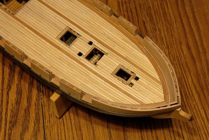
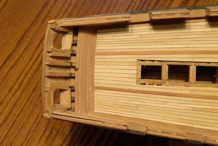
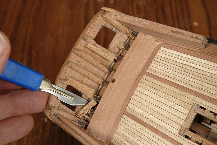
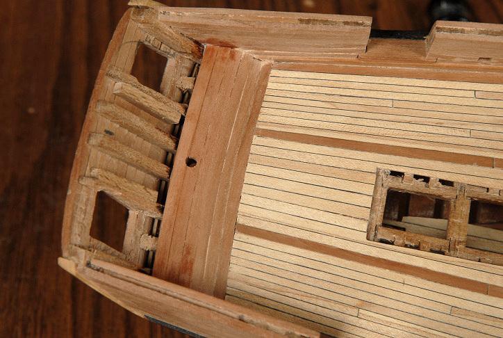
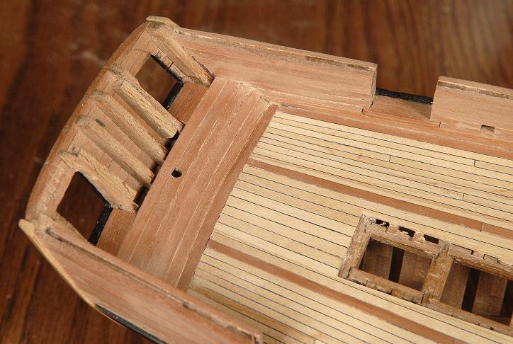
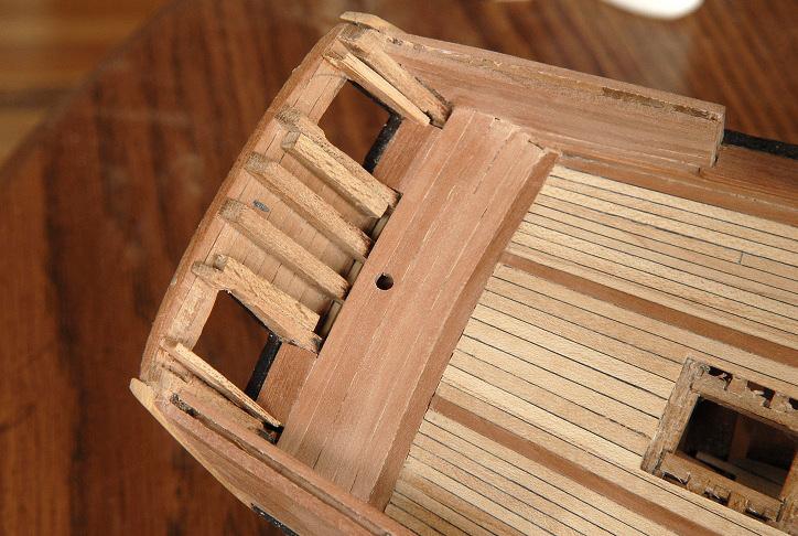
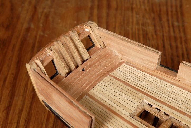
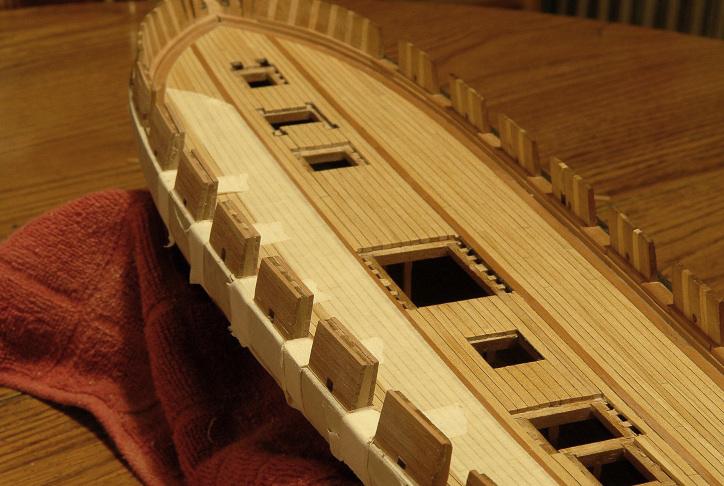
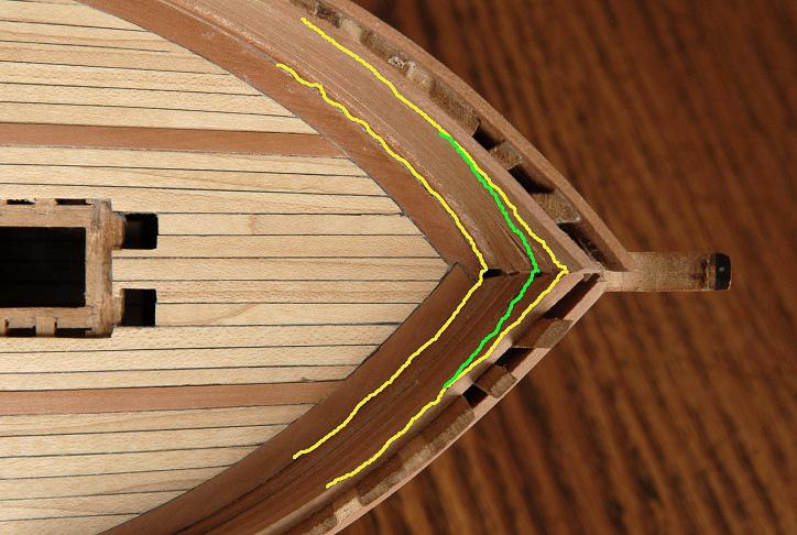
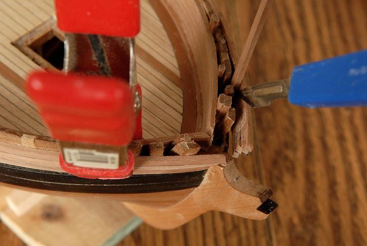
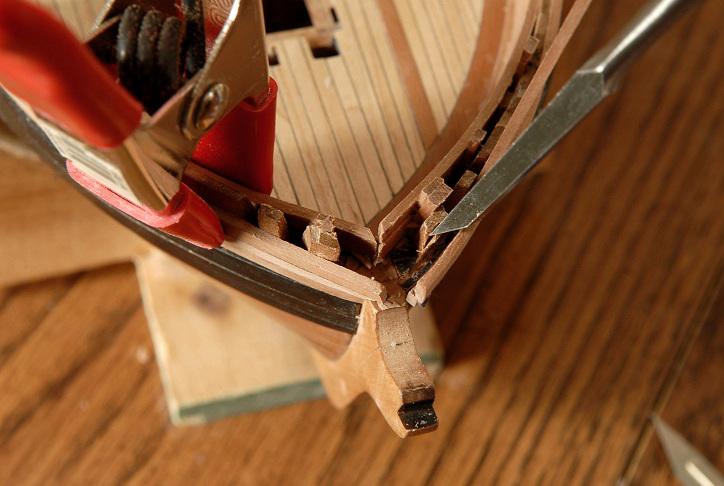
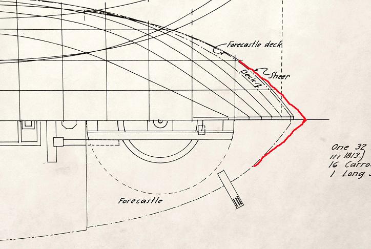
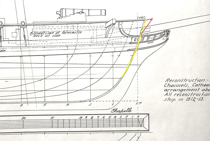
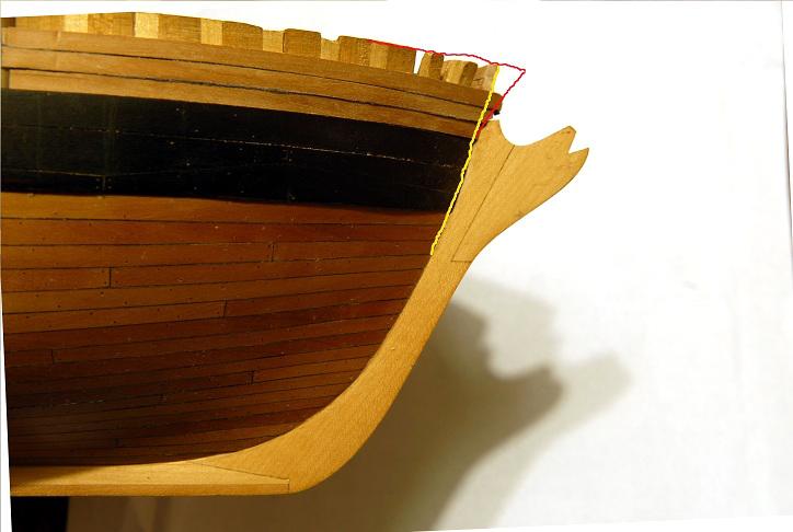
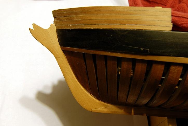
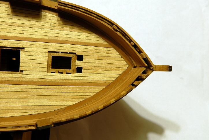
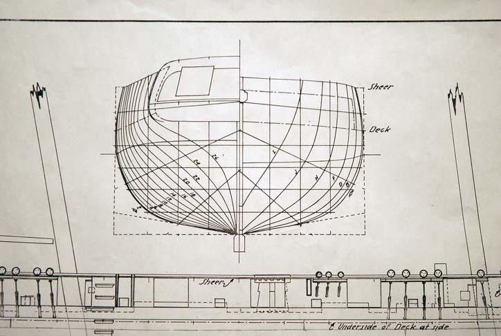
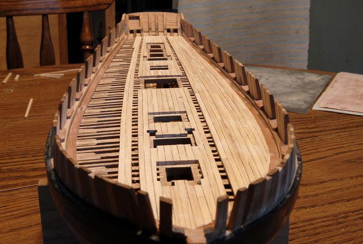
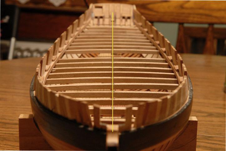
February 3, 2011 Working very sporadically, but some progress: Many of the port side bulwarks have been planked outside and in. Some ports sanded smooth. The planking stock is of varying thickness, so sanding continues to make the bulwarks smooth. Only one of the sweep ports is filed to its final size [i changed the bulbs in my dining room light from incandescent to compact flourescent. My camera couldn't deal with it. The color is horrible. After a few days I changed them back] -- Lots of masking tape to try and protect the gunport sills, deck, and wale during filing and sanding of the bulwarks, gunports, and sweep ports-- I don't know whether or not the inner bulwarks were caulked in actual practice. I have elected to not show caulking there on the model. February 21, 2011 I am plodding along on the bulwarks. Most of the middle bulwarks are planked inside and out, and the port side is rough sanded and the gunports sanded flush. The starboard side has not been sanded yet. None of the sweep ports are done, except one on the port side as a test. The height of the bulwarks is also not to final dimension. As usual, the bow and stern are the trickiest areas, and I'm also trying to be economical with my planking strips, it's going to be a close call as to whether or not I will have enough to finish-- That's all for now. March 7, 2011 Well, I've been working away at the bulwarks. What I thought would be a relatively quick job has taken surprisingly long; mostly because I've been picking away at it pretty slowly. Because it's been pretty repetitive, there hasn't been much to show--but now I have a problem that may be worthwhile to document. I'm now at the bow, and at first it was looking pretty good-- But as the bulwark planking progressed up, the angle where the bulwarks come together seemed to be getting a bit too sharp-- Indeed, I checked the plans, and at the bow, the curve of the sheer (top of the bulwarks) should be following roughly parallel the curve at the deck. You can see the difference here-- I've let a bunch of inaccuracies go, but this one affects the overall look too much. Nothing to do but try and correct it. First is a cut and some trimming at the point where the planking comes together. As the planks will be meeting sooner, I need to trim some length off-- Also, I cut the planking away from the frames on the inside-- And started to shim out the planking until I got closer to the right curve-- After gluing the shims in place, I began cutting the outer planking away from the frames-- Then using the knife and a chisel, I started carving away at the outer face of the frames-- I'll keep you posted on how this comes out--acceptable I hope!. If it ends up looking not good enough, I'll take the planking off completely, and try again. Elia had given me a heads up on this potential problem, but I thought I had gotten it right, as the angle at the deck was good. I hadn't forseen that the angle would change so much between the deck and top of the bulwarks. March 8, 2011 A little more explanation of the problem might help. Here is Chapelle's plan, notice the deck line, and sheer line. The red is where my sheer line was ending up-- Here's the "side view". In my profession we would call this the "elevation", but I think this is officially the "sheer plan". Anyway, the yellow line is a nice smooth curve from the hull up through the bulwarks. Again, the red line is where my bulwarks were going-- Here is the uncorrected starboard side, showing the planks extending beyond the line indicated in the plans-- This is the corrected port side, after my surgery. It more closely follows the plans-- A few different views: The interior bulwarks are both corrected. On the outside the port side has been done, but not the starboard-- Oneida does have a relatively sharp bow, but it is somewhat less so than Niagara, for example. I think I was ending up with Niagara bulwarks on an Oneida hull! All of the lines of the ship need to work together, and I think this has been well worth the effort to correct. Ron


-
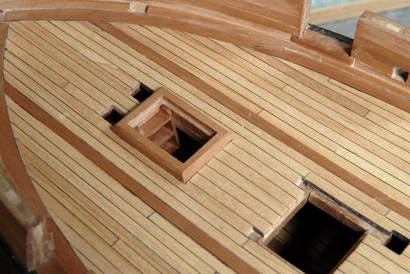
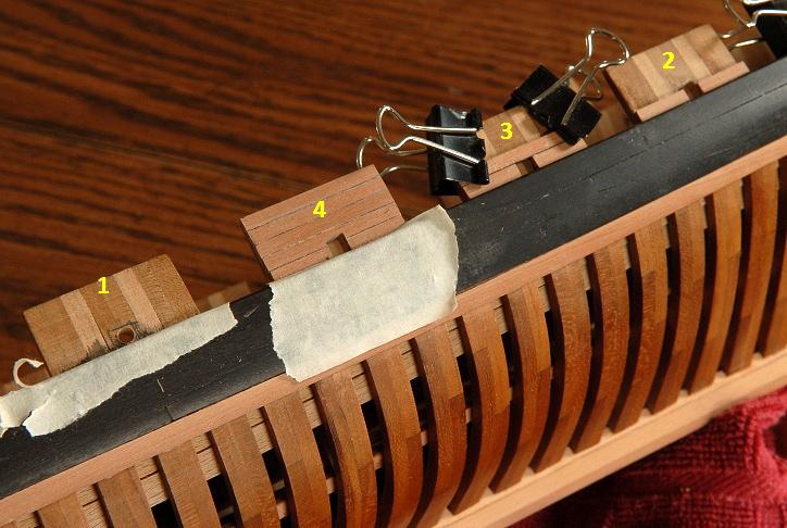
January 16, 2011 Just a small progress update-- 1) First a hole is drilled at the sweep port location, 2)then it is filed square to almost the final dimensions. 3) The planking is glued around the sweep port, and 4) it is filed again-- January 24, 2011 Shipwrights, I have worked on a few various areas over the weekend. For the inner bulwarks, I need some strip wood approximately 1/16th x 1/16th inch, which I don't have. Rather than order some and wait, I figured out a way to rough mill some extra planking stock I have. The milled edge isn't nearly perfect, and it wastes a lot of wood, but I only need about 2 feet, or one strip worth. This way is much easier, quicker and probably safer than trying to cut the hard pear with a knife and straightedge, which was my other option. (Someday, maybe I will have the Byrne's saw.)-- Here are a few of those pieces being glued into place-- I also figured that now is the time to cut the transom ports, as I get ready to plank the inside of the transom. The Chapelle plans show trapezoidal ports-- However, as I framed them, they would come out more square, and at a different spacing. I decided to ignore the framing timbers, and cut the openings as they are on the Chapelle plans. Started by drilling some rough holes-- And I'm gradually filing them to shape. The inner timber gets substantially cut into; I bolstered the side with some extra scrap. For the outer timber I will have to glue a new piece to form that side once I finalize the shape. I also glued the aft margin plank in, and the first transom inner planking piece is pinned to dry after being boiled for a few minuts--it has a slight curve in two directions-- The starboard transom port is getting close to the right size and shape, the other one still has a way to go-- Ron
-
Hi Patrick, I'm happy to be of help! I was hoping to finish the catch-up log this weekend, but I'm not going to make it. Glad you are enjoying it, though! Ron
-
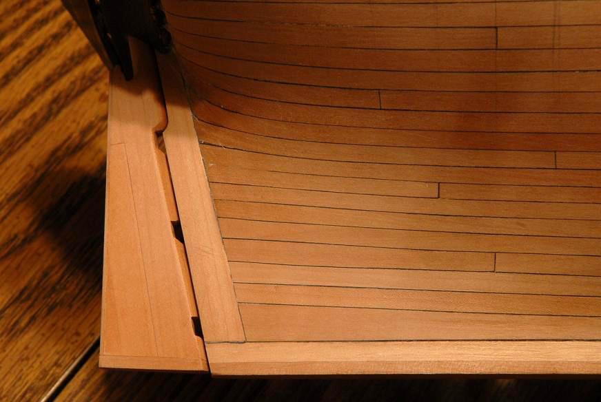
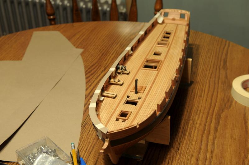
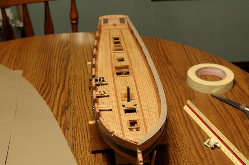
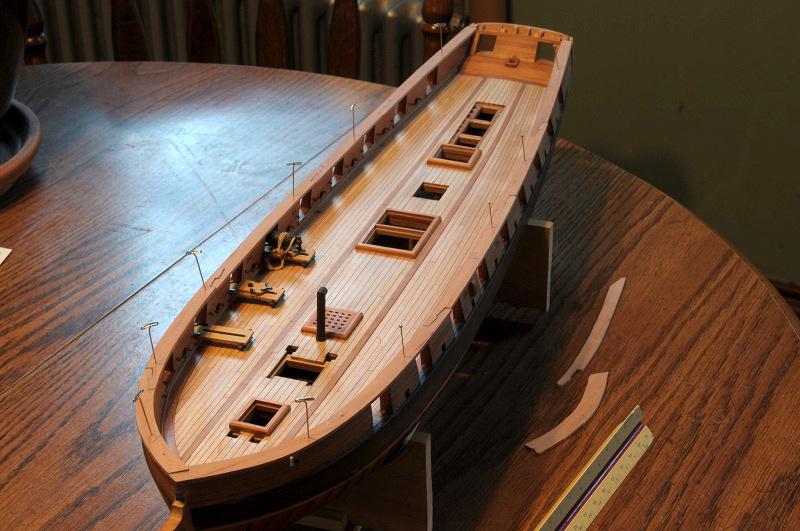
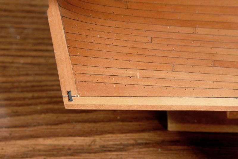
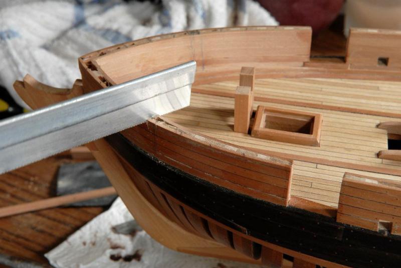
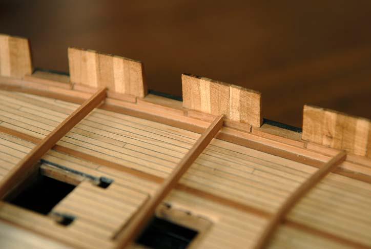
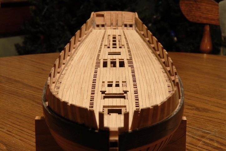
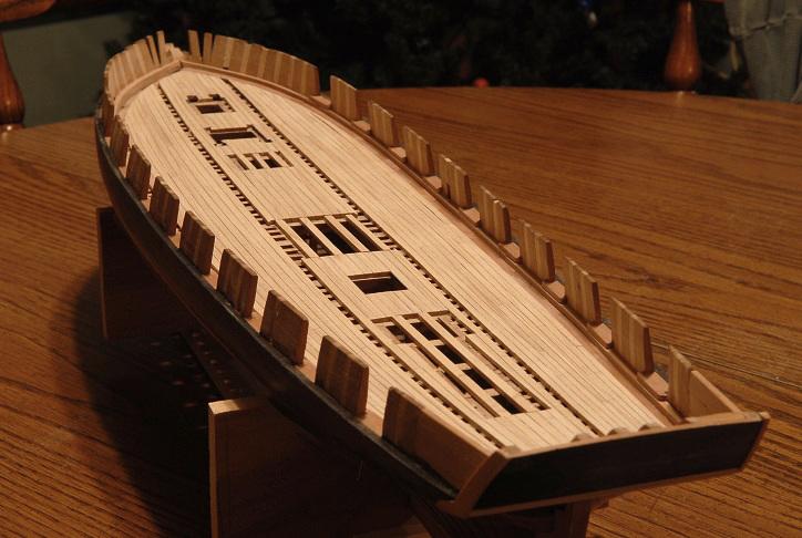
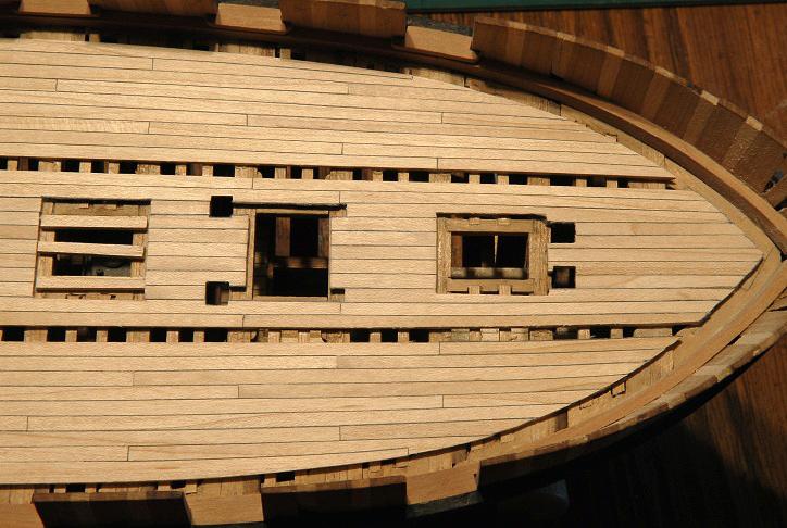
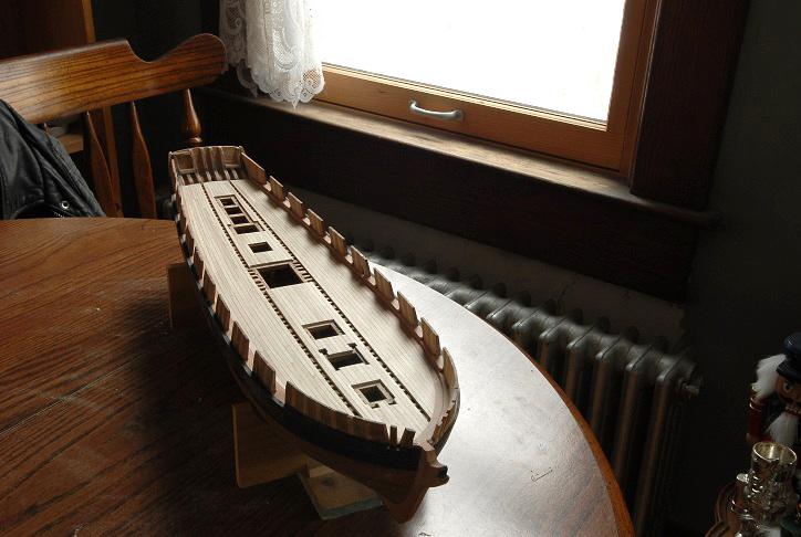
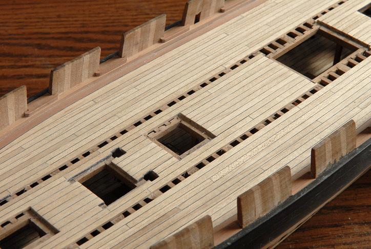
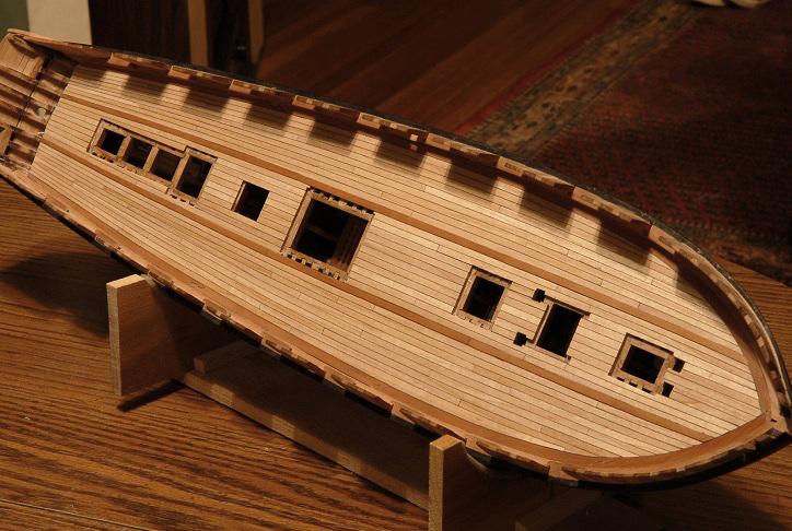
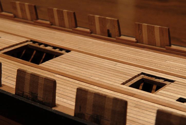
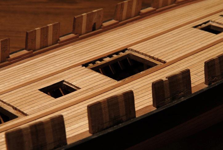
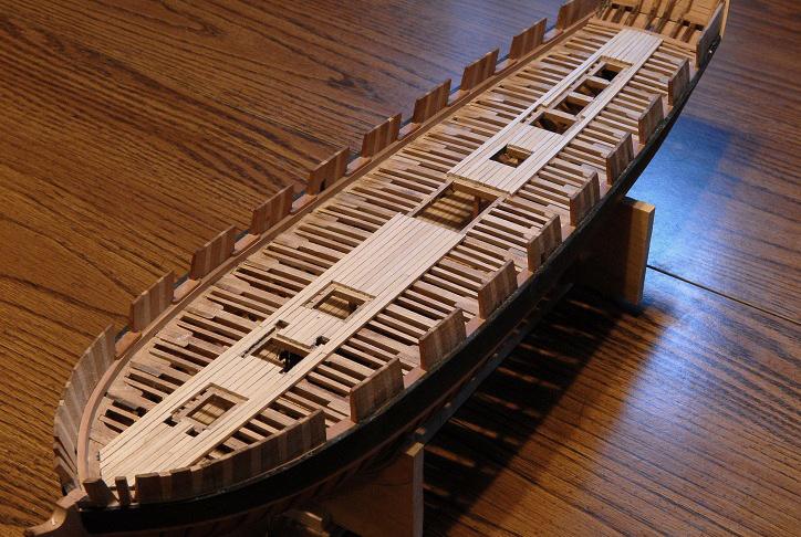
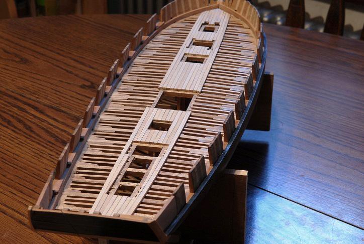
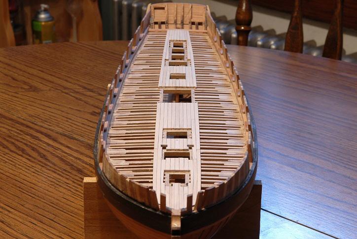
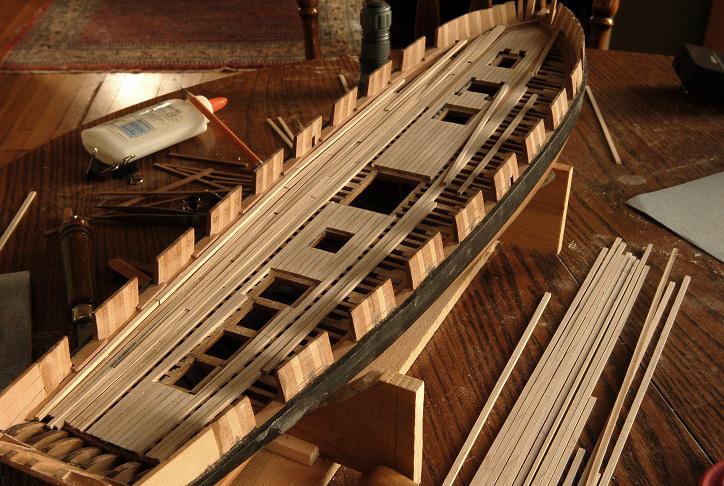
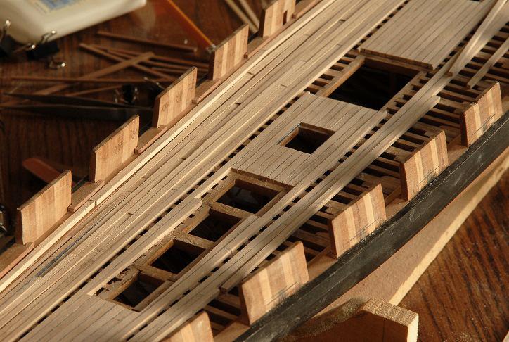
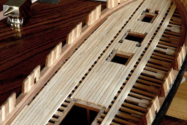
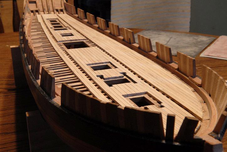
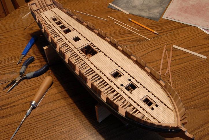
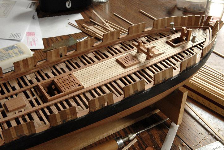
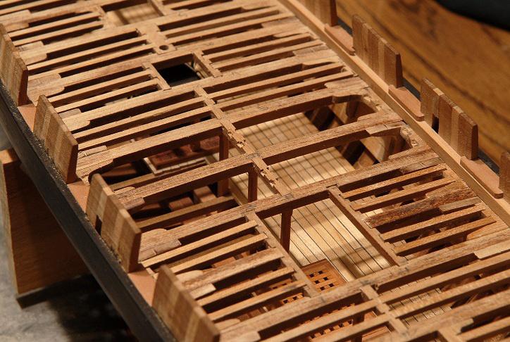
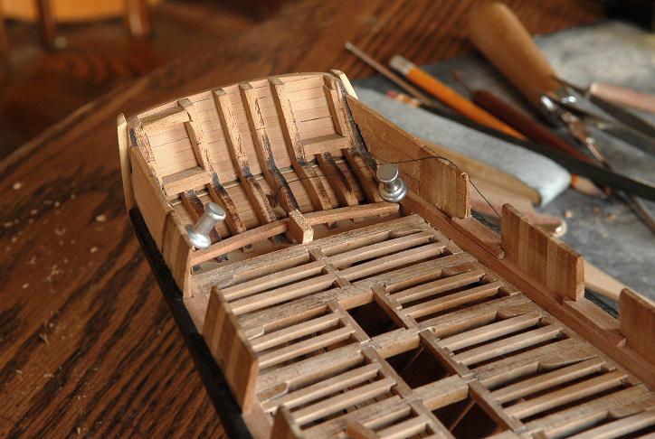
January 3, 2011 It's taken me over two weeks to get to it, but I started the new year off by finishing the deck planking-- Next task is sanding and scraping the deck smooth. Those temporary planks across the hatches are to help with that. The scraper tends to dip down over the hatch, making a ridge in the adjacent plank if one is not careful-- I don't think I'm going to treenail the deck. In actual practice they plugged the treenailed or iron bolt holes so the grain ran the same as the deck (not end grain like a hull treenail) so that the plug would wear the same as the deck. Often the plugs are barely noticable. The forward plank ends will not be nibbed into the margin plank. Partly for aesthetic reasons, because I will have a dark margin plank and I didn't want to highlight the two or three planks that would need to be nibbed. And partly because they would have also happened to fall right at a hooked scarf joint in the margin plank (poor planning there), so I didn't want to complicate that with the nibbed planks. On each side there is one plank that is joggled into a hooked plank-- You may notice that the starboard outside plank, and the one it is joggled into, are larger than the port side. Sigh. The spacing worked out perfectly on the port side, which I did first. But on the starboard side, my deck is wider!! The outside plank had to be made up of two separate planks glued together as seamlessly as I could manage, and then sanded back to the right width. At its maximum width, it is about one and a half times the normal width. I saved two pieces of nearly grainless Maple for this. The hooked plank is also a composite piece. They worked out okay, I don't think the glued joint is very perceptible. I also hope that with the carronades, cannons, and all the rigging, that the difference between the two sides will not be very apparent. [Well, I had completely forgotten about that terrible asymmetry until reposting this.] January 8, 2011 The margin planks are glued in, and the deck has been sanded smooth-- You can get a glimpse outside of the snowy weather we had yesterday and last night. I'm not a fan of winter, but this was a pretty snowfall-- The temporary planks have been removed from the hatches-- Next up will be installing the binding strakes. [i learned their correct name.] January 10, 2011 The binding strakes are glued in-- This was more diffictult than I thought it would be. The planking is actually slightly uneven in height (due to a multitude of causes--uneven deck beams and uneven sanding being the primary culprits), and to make the binding strake a consistent inch or so (in scale) above the deck required some shimming of the binding strake on the deck beams, and careful scraping. There's still some fine tuning to do, but it's mostly as good as it's going to get-- I think I can put off planking the bulwarks, inside and out, no longer. That along with cutting the sweep ports, will be next. Ron


-
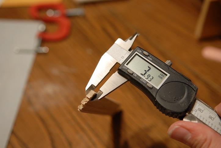
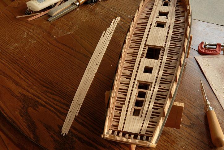
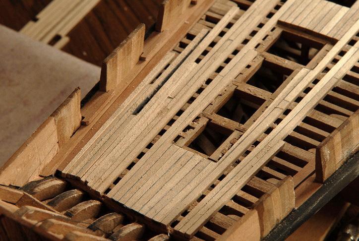
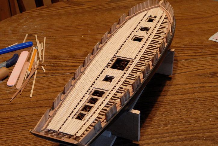
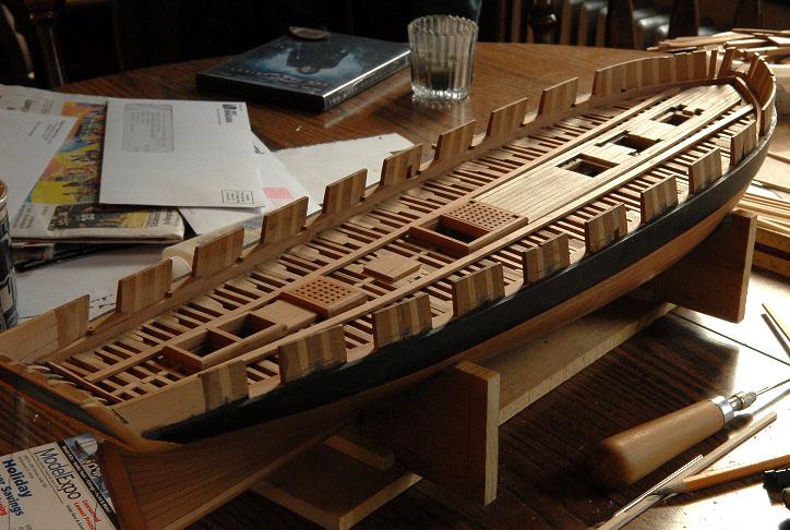
November 21, 2010 This work was more time-consuming than I thought it would be, working out the taper both fore and aft, and cutting the planks around the bitts and hatch coamings. I had to adjust the width of the planking strakes, and shave some width off of some of the hatch coamings, and the main mast partner piece, to make it work out. Here's the center portion planked, with all the "deck furniture" removed-- November 27, 2010 Hello shipwrights, Small bits of work this past week-- First I glued some 24 foot (in scale) planks together, in order to more easily sand a taper into a bunch at once. Individually they get very difficult to hold against the sand paper. (I have sanded off the tips of my fingers once or twice). This is the unsanded width-- And here is approximately the width I need at the narrow end. This is a little fat still, but I don't want to accidentally make them too narrow. I'll adjust as I glue them-- I have temporarily glued the ringbolt strake in (also tapered in width), and have begun gluing the rest of the deck planks on-- The last picture shows my supplies for this work: a bunch of roughly tapered planks (separated back into their individual pieces from the "block" shown in the first photos), strips of paper caulking, sand paper, sanding block, emory board, glue, pencil, and gluing clips. I'm also using a small saw for cutting the planks to rough length-- Hoping to make some visible progress this weekend. November 28, 2010 A dozen or so planks done today, in between other chores. The ringbolt planks are removed now-- Lt. Woolsey observes the progress in the shipyard-- After thinking about it, Lt. Woolsey had an idea. Unlike the hull, where the multiple curves make it impossible, the carpenters could actually lay out the planks, to make sure everything will fit right. So that's what they did. Here are the port side planks cut to length and laid on the deck, in position-- The last row of planks are sitting up on the margin plank, because at the ends, they don't all fit yet. Still a little fat. But now I have it planned out, for the port side at least. After I glue up this side, I'll mirror it on the starboard side. I also haven't finalized the bow planks. Still thinking about the nibbing-- Then all planks were removed and laid out on the table-- I then worked on thinning down the widths of the aft end planks. Here they are dry fit-- Gluing the planks can resume. November 29, 2010 Jim Lad wrote: A cunning trick Ron - making sure they all fit property before you unlimber the old glue pot. Ha! Sometimes the obvious path takes me by surprise! Another weekend has flown by. Only half of the port side planks you see here are glued. There was much trial and error sanding and fitting of the planks to make them fit nicely. The bow is still "to be determined". I think I will try to avoid nibbing the margin plank. I might be able to close up the bow with just one or two joggled planks. I'll have to cheat though, I only have maple planks in one width, and I'll need a wider plank to do the joggling. If that's what I end up doing, I'll try to "invisibly" glue small additions where needed to the planks. December 9, 2010 Not much time for modeling lately, but I have finished the deck planking on the port side. Here is the space for the last plank. This one is joggled into the previous plank at the bow, and that is the only joggled plank. No nibbing. I notched out that plank to approximately half it's width-- Here is the port side all glued with the margin plank placed dry-- And some photos with the margin plank removed-- I have done some minimal sanding to the planking that's been done, but the real smoothing and finishing will wait until the starboard side is glued down. After all is sanded smooth, the margin planks, binding strakes and hatches can be glued for good. Ron

-
Wait...wasn't Stairway to Heaven ABBA? Håkan, you'll get that boat right next time, and it's not the first model I've seen that skipped the tough little guy. I'm dreading it myself. Ron
-
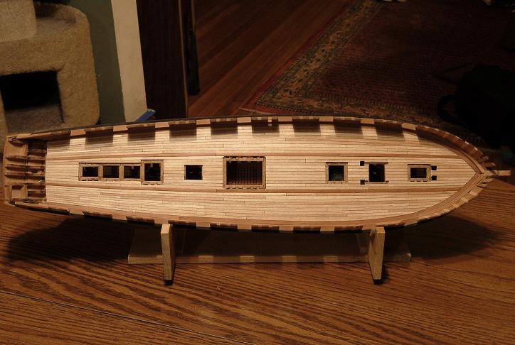
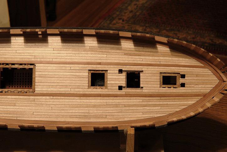
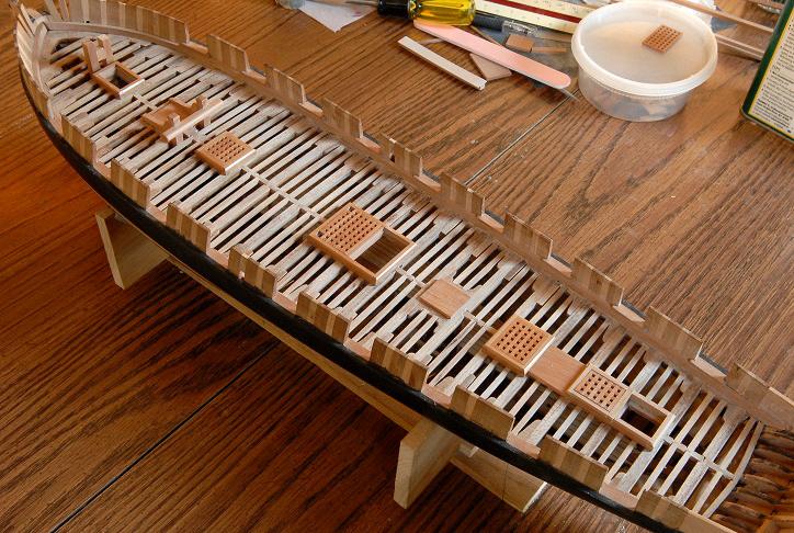
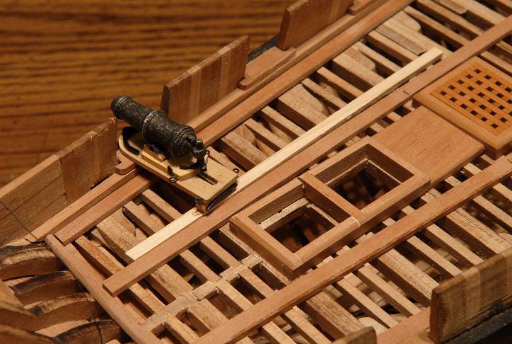
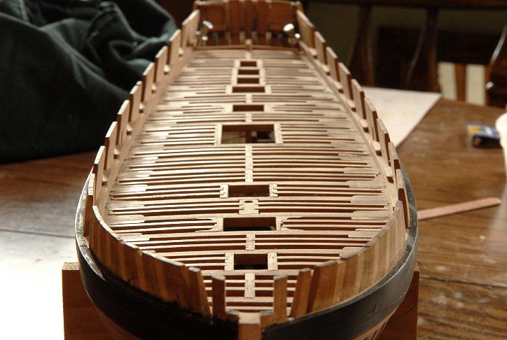
November 7, 2010 I have continued making the pieces that will determine the deck planking layout. I have them just about done. They are very lightly glued to the framing. After I install the deck planking, I will take all these off to scrape/sand the deck, then put them back on more permanently. I think that the only other pieces that the deck planking goes around are the pumps, but I think I will wait and cut those through the deck, instead of planking around them now. The jeer and topsail bitts fit within the square of the mast partner pieces, so I don't have to do those yet. The bowsprit step is just a "placeholder" at this point--it needs a lot more work, but will suffice as a guide to plank around in the meantime. I will also finish the aft companionway and skylight (if I choose to do that instead of the hatchgrating), and capstan, after the deck planking is done-- As I started to cut my first deck plank, the middle plank right at the bow, I realized that I don't have wood for the margin plank! Arrgghh! I will have to send off for a few pieces of wider Maple to make up the margin planks. While I await that small wood shipment, I will work on the bulwark planking, and treenailing the wale. November 9, 2010 While looking at some photos of other models (the 74 by Dmitry Shevelev in the "Completed Ships" topic here [sadly, as far as I know this has not made it back on MSW 2.0], and two by Frolich) I noticed that they used a dark margin plank. I was excited to see this, and decided to make my margin plank out of pear. I think it looks good, and I won't have to order more wood. I cut some forward planks from wider stock, and once I made a good fit against the waterway, transferred the line for the inside edge. For the rest of the margin planks I will use straight stock, since the bend is not so severe,and there won't be as much nibbing-- November 12, 2010 I continue to work (slowly) on fitting the margin planks-- November 15, 2010 The margin planks are cut and laid in place. They are not glued down yet, because I'll have to remove at least the bow pieces to do the nibbing. I have decided to show the heavier planks that carry the ringbolts along each side of the deck. (what are they called?) These are tacked down like the hatches. After I lay the deck planking they will come off, be cut into separate planks, then reinstalled-- I have made them curve in at the stern, and so I will also be tapering the planking there. I don't think I would have gone through the extra work of this (especially as I don't know if it would have been that way on this ship), except that the stern is very tight, and I didn't want the last carronades to overlap the ringbolt plank. I've made it so the last carronade is barely clear-- After pondering a bit, I will also taper the forward planking. It seems inconsistent to not do it forward if I am going to do it aft. I haven't determined the exact curve yet, so in this picture the ringbolt plank is straight, but as I start to glue in the center planking, I will figure out the curve and taper of the planks. The center planking between the hatches is just cut and laid in place; not glued yet. The few planks at the bow are glued. I hadn't decided to curve and taper the planks when I glued those, and I will have to decide whether I can leave them, or if I will have to remove and redo them to accomodate the curve-- I have tried to base a lot of my guesses about various details on Glenn Grieco's model of Jefferson. That model is also a Lake Ontario brig, built just a few years after Oneida. That model is based on archological research on the Jefferson's sunken hull. It's probably as accurate a model as can be made. However, surely some of the details are "reconstruction" work (to use Howard Chapelle's term). Jefferson was equipped with mostly carronades, but the model shows the wider, thicker ring-bolt plank-- It's interesting that the ring-bolts are shown only at the midship area of the deck, and not at the aft end. They are also spaced closer together than would be needed for just the gun tackles-- My guess is that the deck might incorporate the ring-bolt plank for flexibility--giving the option of fitting out with either carronades or long guns, and also the ring-bolts may be used for general lashing points; or other rigging uses I may not have a clue about. Anyway, I will have two six pounder long guns in the bow, so the ring-bolts will be needed at least there! November 20, 2010 So, ringbolts will be included. I also looked at the Syren brig, and though it is rigged with carronades, in has ringbolts also. But, they are a ways away. Little progress--I have finished the planking that lies between the ringbolt strakes, forward of the main hatch-- In the next picture I have removed the various deck pieces within that area of planking, for easier sanding-- On to the middle rear planking, then the ringbolt strakes, then the rest of the planking. Ron


-
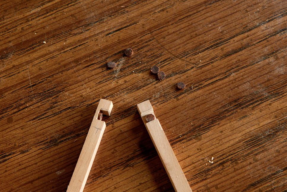
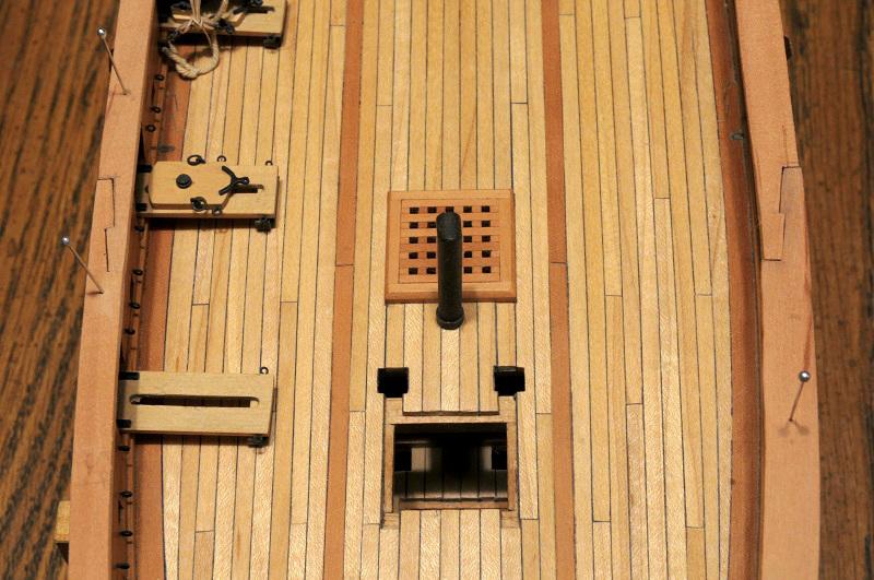
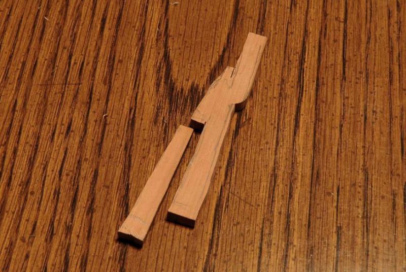
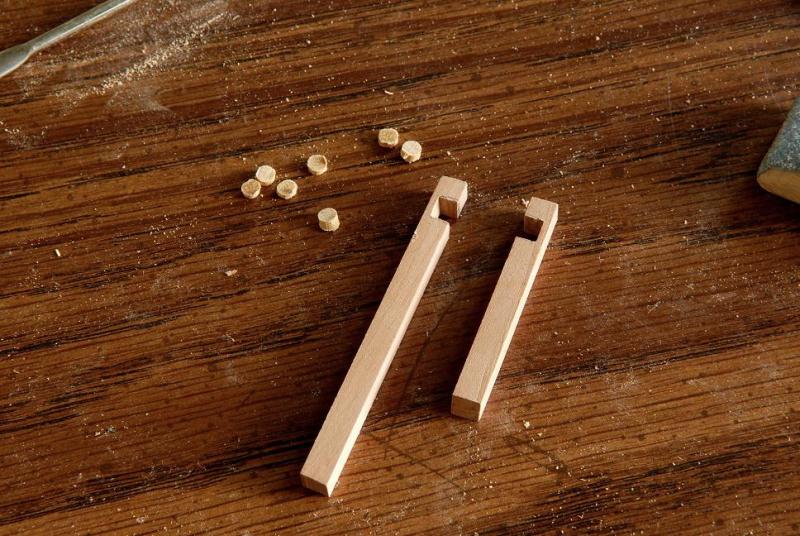
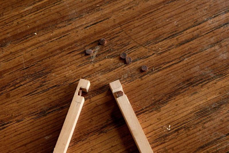
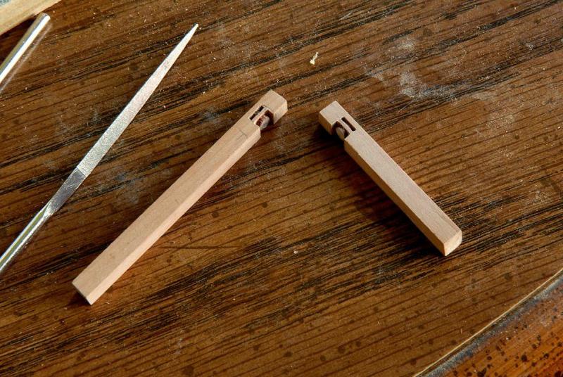
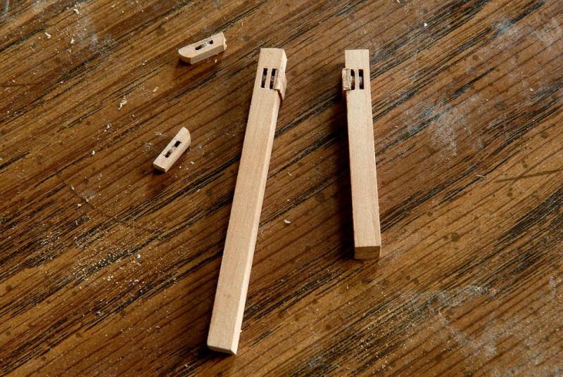
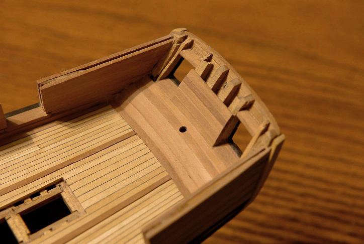
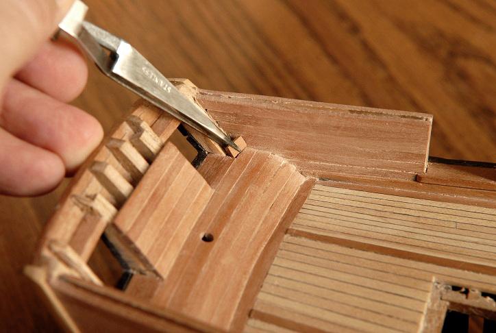
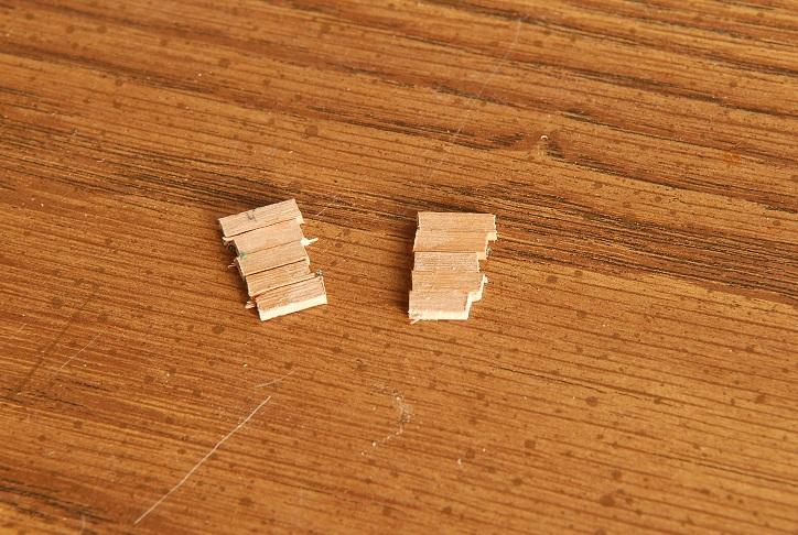
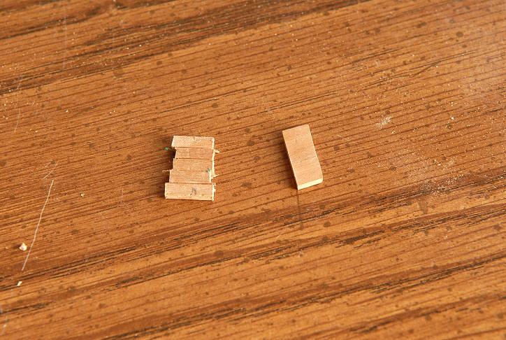
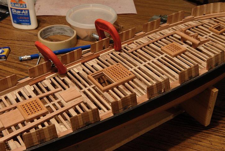
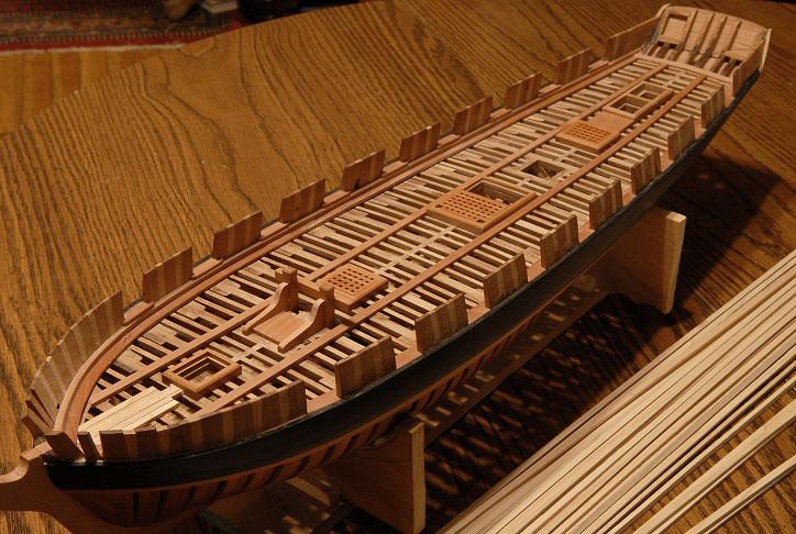
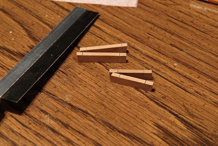
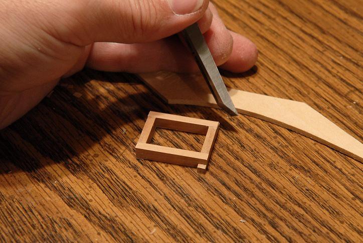
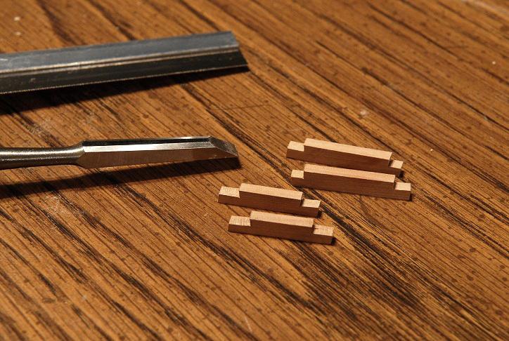
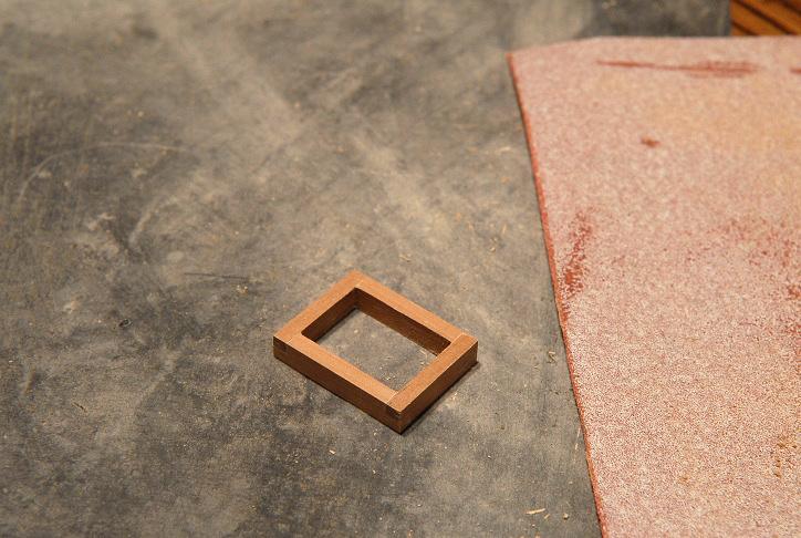
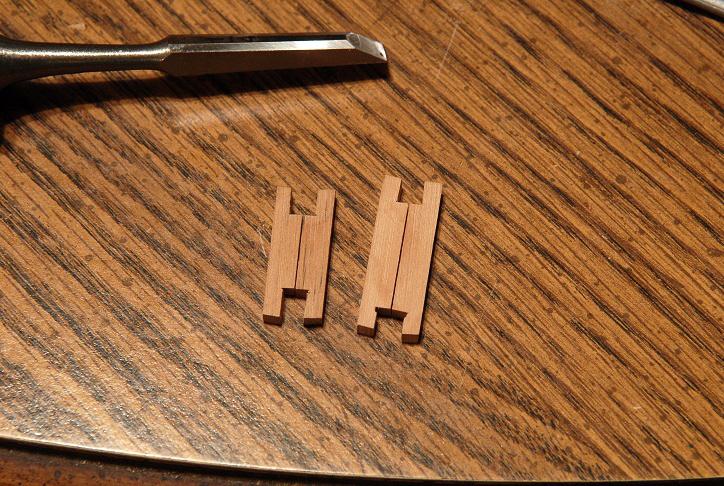
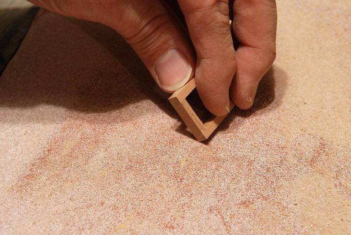
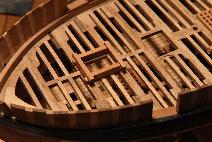
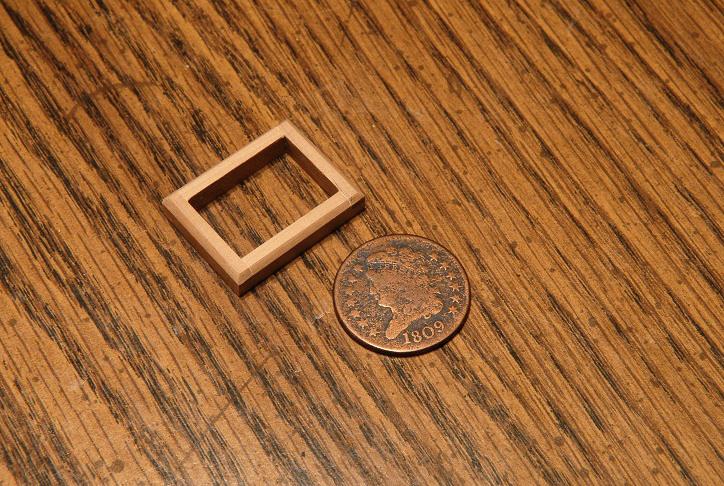
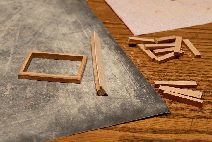
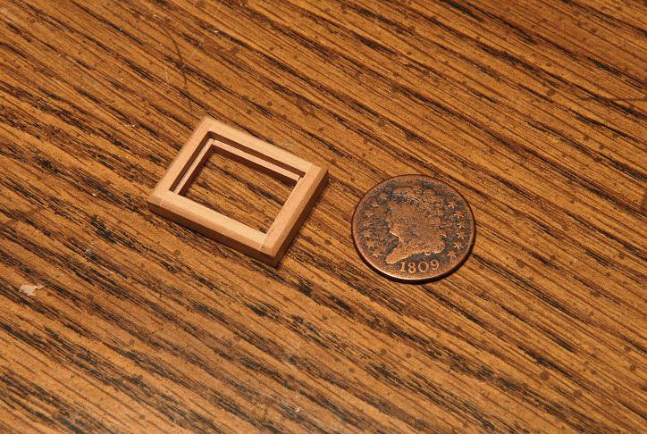
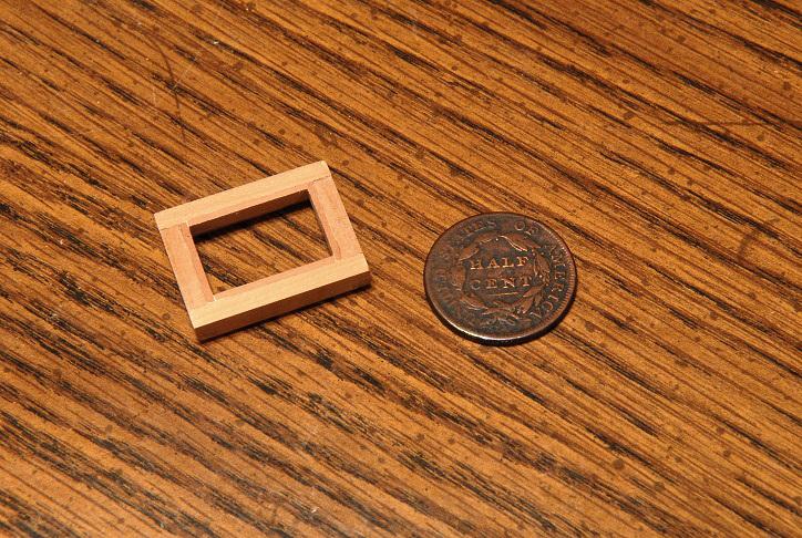
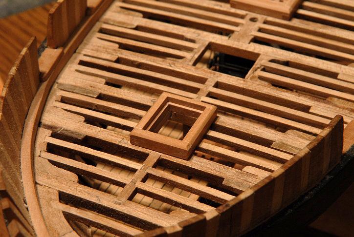
November 3, 2010 I've begun work on the hatch coamings. The main hatch coaming is glued and sanded, With some thin pieces I will need to glue a ledge on the inside for the hatch grating to sit on. I had one extra deck beam, so I glued an emery board to it, to sand the deck camber into the coamings and hatch gratings. On the right are the pieces for the smaller hatches-- November 4, 2010 Once in a while I get the urge to go into a little more detail about exactly how I am doing things on this build. This is one of those times. Not because I am any kind of expert, but you might be interested in how one person does something. Anyway, it's fun. So here is a step-by-step building of one of the smaller hatch coamings. This one will eventually be fitted with a ladder. First thing I do is roughly measure the inside dimensions of the hatch, and make a saw cut about halfway through the pieces- Then with a chisel, they are notched out-- The notches are squared up and adjusted to final fit. The pieces are checked often to make sure the notches result in equal lengths-- Periodically the pieces are placed on the deck to see when I'm getting close to the right fit-- When the pieces form the right hatch size, they are glued-- After the glue sets, the protruding ends are pared away with the chisel-- Then all six sides are sanded smooth-- Here is my highly precise method for chamfering the outer edges. I tend to do a lot of things by eye-- But the result is acceptable to me-- Next I glue thin strips to the inside, and it's done. [Mistake here--these strips should only be on two sides--but can't remember now whether it's the sides or the front and back] Heads-- Tails-- And here is the finished coaming placed on the deck-- I have done the forward 3 hatches-- Just a couple more to do. I am considering making that last small hatch a skylight instead. The opening aft of that will be a companionway-- Ron


-
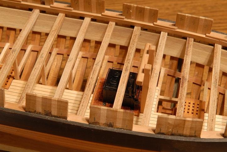
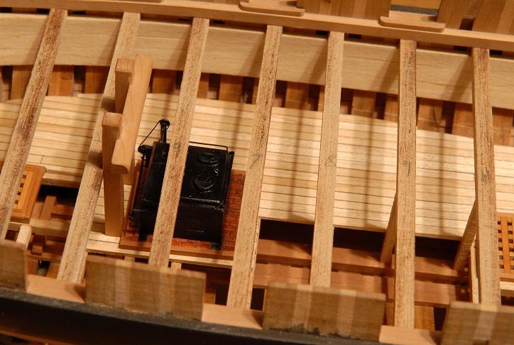
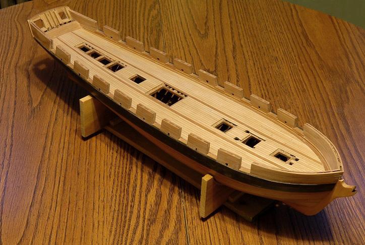
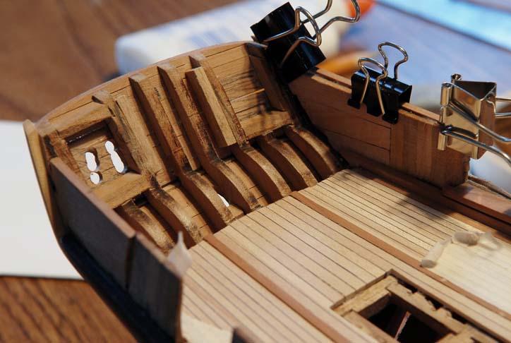
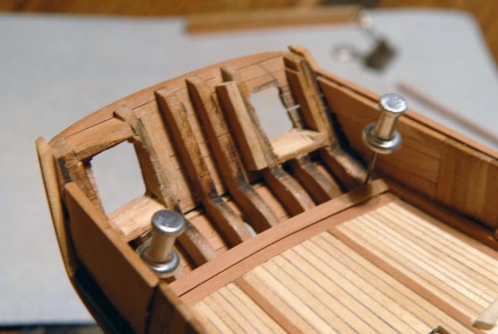
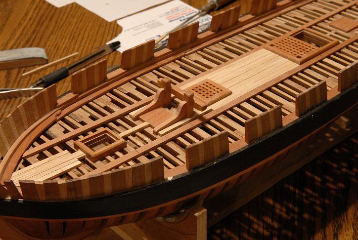
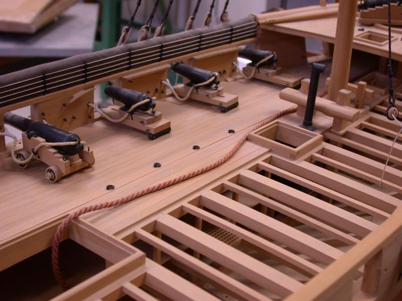
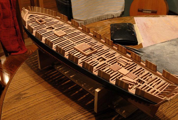
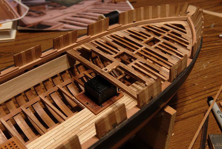
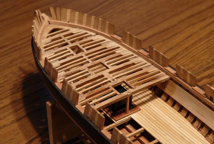
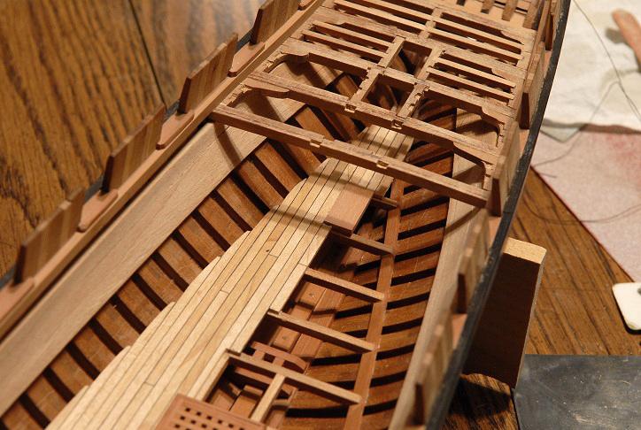
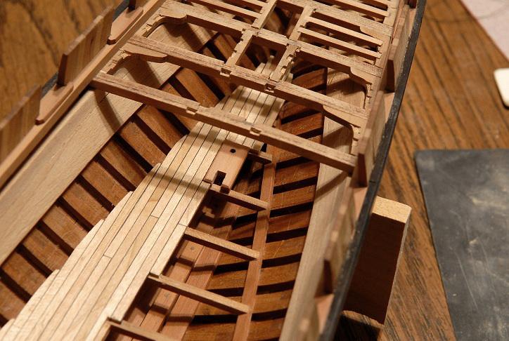
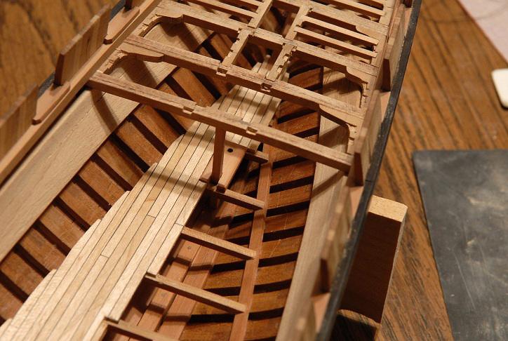
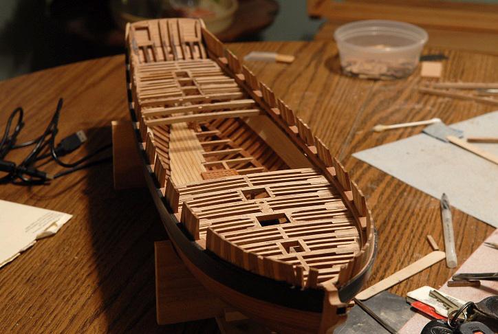
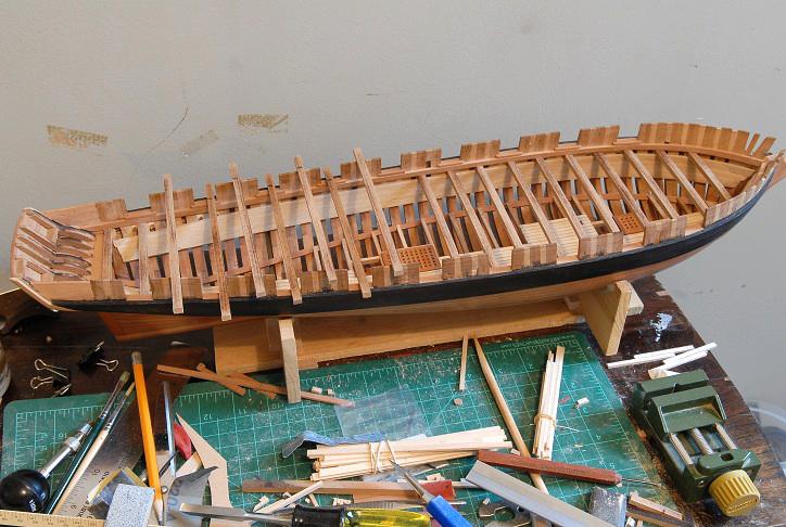
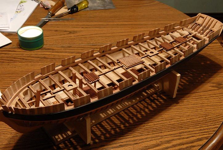
October 14, 2010 Progress shots--the deck framing around the forward mast partners is done, and I'm working on the area around the riding bitts and stove pipe-- Soon the stove will need to be glued in. I'm a little apprehensive about gluing such a fragile piece on at this point, but if I continue with the deck framing I need to do it now. I'm having some thoughts that I should stop the deck framing, and do the outer bulwark planking, so I can drill the treenail holes for the wales and bulwark planking without worrying about something happening to the stove as I turn the model on its side. On the other hand, if the stove is glued well, and I'm careful, turning the hull should not affect it. October 17, 2010 I've glued the stove in place, and am progressing with the deck framing-- There is not much height between decks! But I don't think I'm far off. My Lt. Woolsey measures 6'-2 1/2" to the peak of his hat. I am much shorter than that, and on my visit to the Niagara replica, I could not stand up on the lower deck. On what little information I could find, 6' deck to deck seemed like a reasonable guess for this ship. October 18, 2010 I had to stop working on the forward decking. I hadn't reached the main hatch yet, but I was just past the widest part of the deck and realized that I wouldn't be able to slide my beams in as the deck narrowed aft. So I began working from the back end. Here's the progress-- October 19, 2010 I did some surgery to make a base for the capstan pivot-- I am improvising some of this. Someday, I will buy the books that show me how these kinds of details really should be done, but for now, it's enough for me to practice on-- A few more ledger beams fit and glued, but overall not much different-- October 20, 2010 Another beam done. Assorted beams, knees, carlings waiting to go in-- October 27, 2010 Just a small update--I have run out of the kit laser cut lodging knees and have to cut six more from some scrap wood. Then I will be able to finish the main deck framing-- October 31, 2010 Happy Halloween, all! The last few steps of thedeck framing are underway. This shot shows the main hatch framing partially done. There is just enough space to insert the last beams diagonally, then straighten them into their recesses-- Here I've put one of the two last regular lodging knees in. When I glue the other one in, that last deck beam will no longer have room to rotate diagonally to be removed-- Last knees to go in are these special ones. This is the point where the hanging knees switch from the forward side of the beams to the aft sides, so in this gap are these "u" shaped double lodging knees, similar to what is in place at the mast partners-- All that is left here are 8 ledger beams to go in-- At the stern, I have notched a piece to fit up against the transom framing. It has a double curve, and I've boiled the piece and pinned it to dry-- Nearly done!-- The deck framing needs some sanding, and that last bit at the stern glued. Then I think it's on to the hatch coamings, then decking, then bulwark planking. Took a break to carve a big vegetable instead of deck knees-- Ron


-
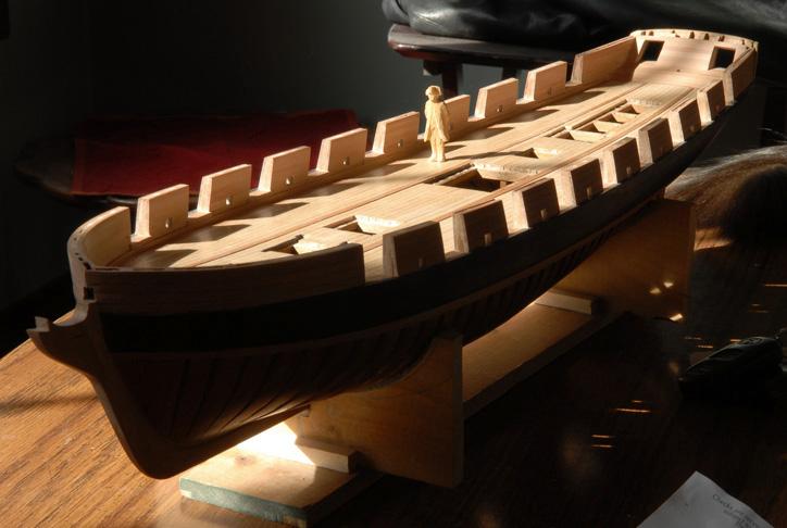
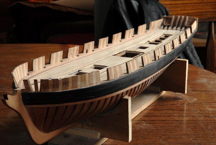
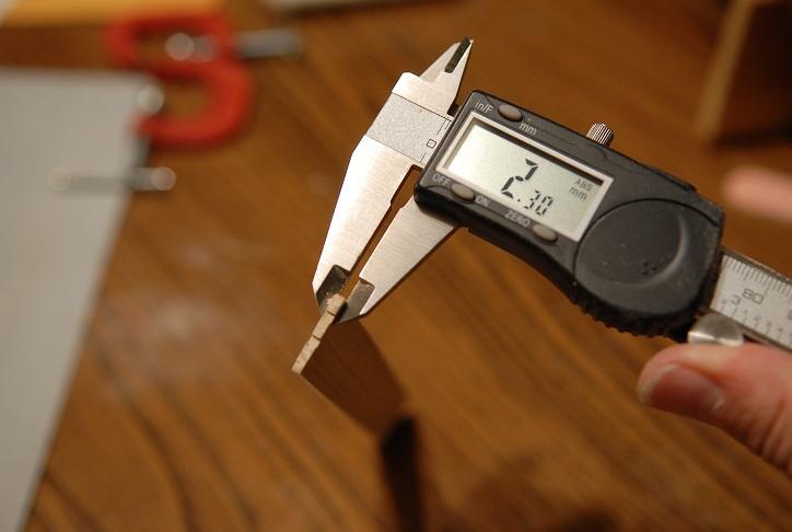
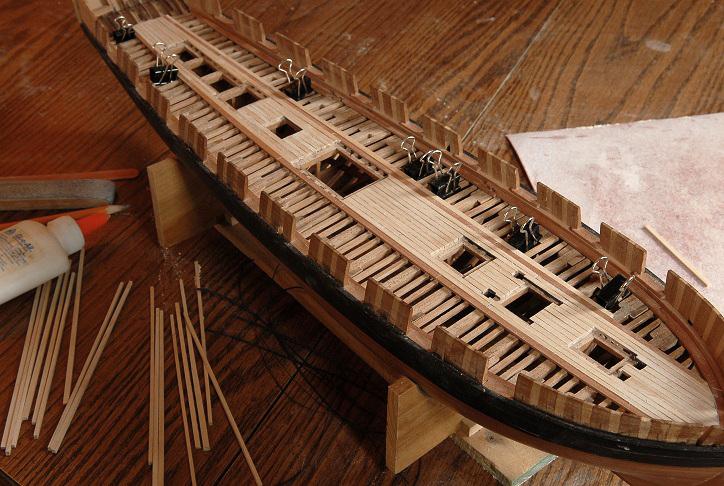
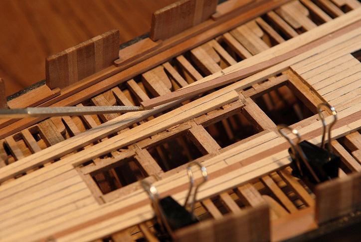
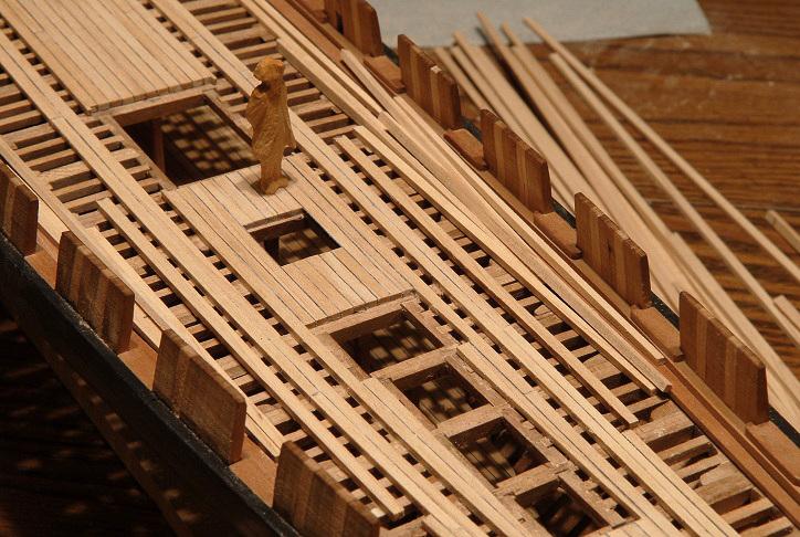
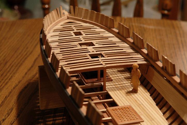
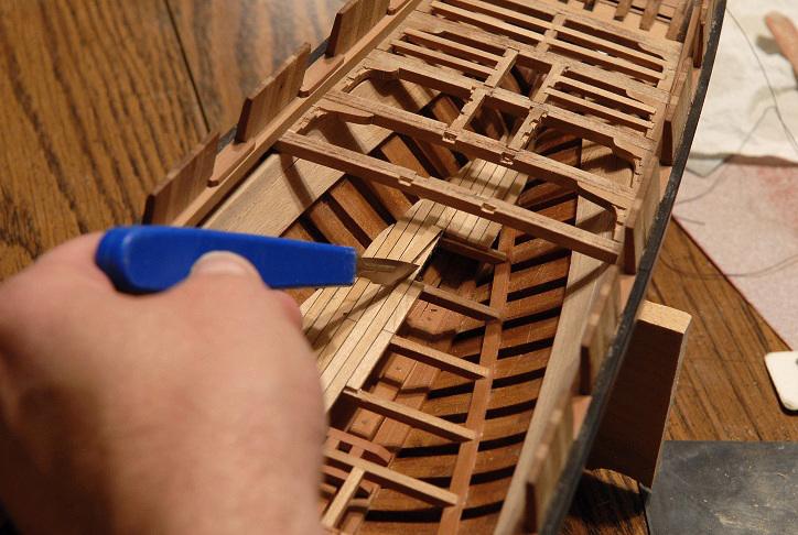
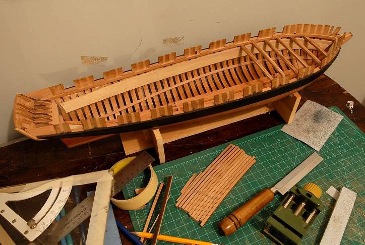
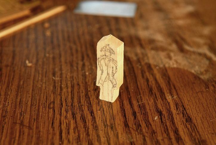
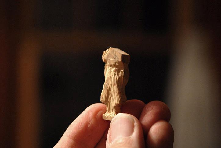
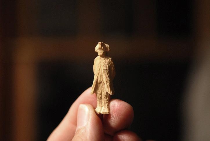
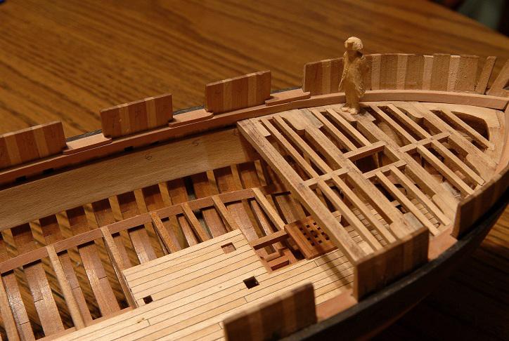
August 19, 2010 Cutting the main deck beams to correct length, and testing their position-- September 12, 2010 I'm halfway through trimming the main deck beams and dry fitting them. Having them in place will allow me to cut the support pillars to the proper height-- All beams cut, sides and bottoms sanded. The tops will remain rough because I'm afraid I'll mis-shape the camber if I sand them more-- October 1, 2010 I cut all the center posts, and started to shape them. Then, upon thinking things through a bit (always a good thing to do), I realized that I will have to do the deck carlings, ledges, at least dry fit, before installing the posts. This is because most of the notching of the beams and other deck framing will be much better done off the model, and some slight horizontal adjustment of the beams may be necessary to make everything line up true. So the posts are put on hold, taped with a number ascending from bow to stern. The post on the left I had already shaped, chamfering the corners on the portion between the berthing deck and the main deck beam-- In preparation for starting the beam work, I taped a thread down the center, and positioned the beams-- You can see I left one post in place (for no particular reason). That post I had to cut through the bricks and deck planks underneath-- Then I made a mark on each side of the thread, to denote the center point of each beam. You may notice the fifth beam up from the bow looks askew; it shifted at some point between marking the beams and taking the picture-- October 7, 2010 Slow and painstaking start to the deck framing. Most of the pieces will have to be adjusted from those that are laser cut in the kit, due to the different beam spacing I am using. (Didn't see that coming!) I am starting from the bow and working back toward the middle. Then I will probably go to the stern and work forward. This is due to the fact that I glued the waterway pieces in long ago, so my deck beams can't simply be placed down on the clamps, they have to be slid sideways into position. I sure hope this works! Here are the first pieces. Some are glued, some are just dry fit-- This is one of the hanging knees that will need to be inserted-- These pieces are glued, though the knees have just a tiny spot of glue holding them. I will probably remove them to cut the notches for the ledges-- And the rest are just being fitted-- October 9, 2010 In the next photo you can see that where the main hatch will go, there is a beam missing, because that one doesn't go all the way across. Hopefully that will provide me with a big enough gap to work the last couple full beams in, and then finish with the divided hatch beam. I laid all the beams in, with unfinished hatch gratings, mast partner pieces, carlings, etc, to check my deck layout. I think it will work. The bowsprit step may be a little too far aft, but I would have to respace my forward few beams to fix that, and I'm happy with the way they are spaced, so I'll leave it. If it really looks wrong later, I can cheat and put it closer to where it should be-- Here's a more messy in-progress view-- After shaping a pair of hanging knees, I glue them to the beam they support-- Then I dry fit it in place, to help with the shaping and trimming of the lodging knees-- When I have the lodging knees trimmed to fit snug against the hull, and trimmed to the right length between the beams, I need to mark the locations of the notches for the ledges. In the next photo you can see the laser cut markings for the notches, but they are not correct anymore, due to my different beam spacing-- I lay some ledge stock across, check the spacing and mark new locations of the notches-- Here at the forward companionway, I have half of the carling and ledges dry fit-- The shadow you see where the ledges notch into the carling is not a gap, but the ledges are slightly higher than the surface of the carling piece. Two reasons for that, one, it allows me to cut the notch just a little shallower, which helps immensly, and two, the ledges don't have any curve to them, and if I leave them just a little high at the ends, I can get the right curve when I sand the deck down after it's all glued. Cutting the notches in the lodging knees and carlings is testing my patience. The cherry is very dry, and likes to split. I have to be constantly vigilant in adjusting the force I am using with the chisel, depending on which way the grain is running. I have split a few, and had to wait while I glue them back together. My work on the notches, especially at the knees is not the greatest, but hopefully I'll get better as I go. October 11, 2010 Here's a shot of the billets of laser cut knees. I have to be careful not to crack them in half (as I have done to some) when I extract the next set to work on-- Now I have added one of the beam stanchions-- Here you can see some newly added ledgers, which clearly don't follow the camber of the deck compared to the previous set forward, which have been roughly sanded to follow the curve of the beams-- After seeing that picture with the stanchion, I decided I wanted a scale figure to inhabit my Oneida. I cut out a small block of boxwood, and drew on it a hands-behind-his-back captain-- And after about an hour of carving he begins to emerge-- October 12, 2010 There are a lot of deck beams! So I am taking a break from them to finish Lt. Woolsey, who oversaw the building of Oneida-- Lieutenant Woolsey is on the scene now. Everything should come out right-- Ron


-
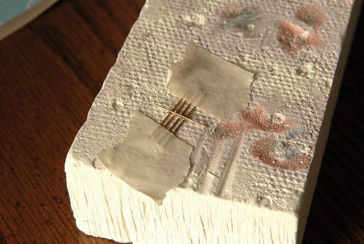
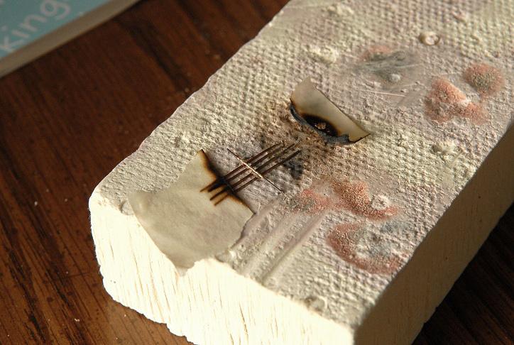
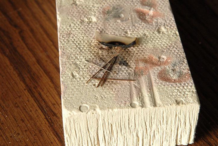
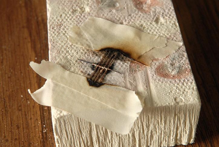
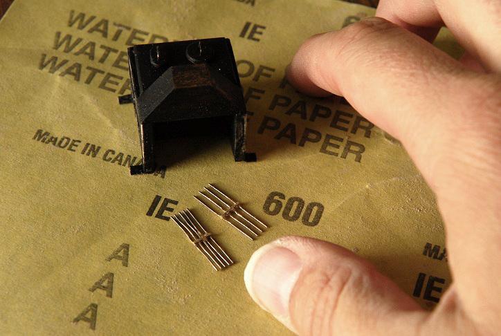
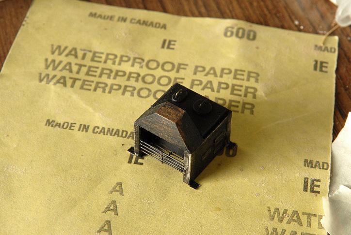
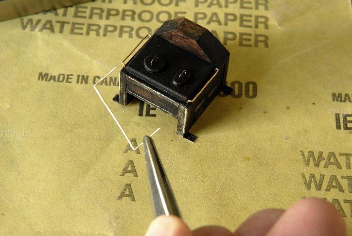
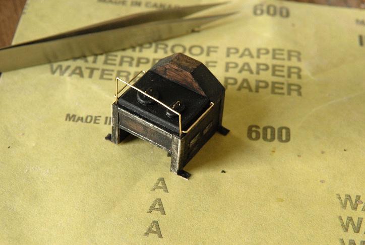
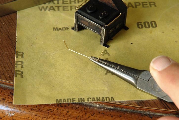
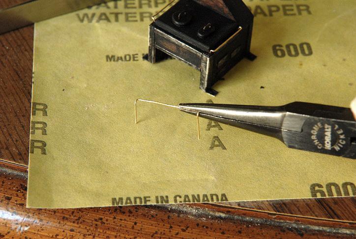
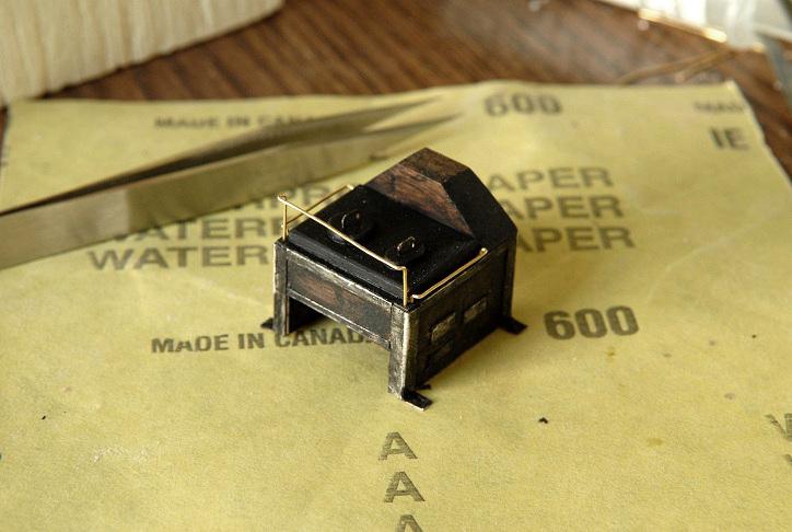
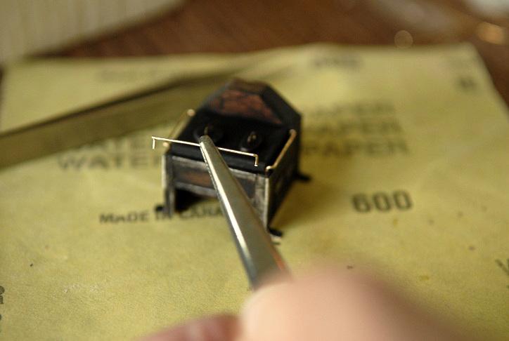
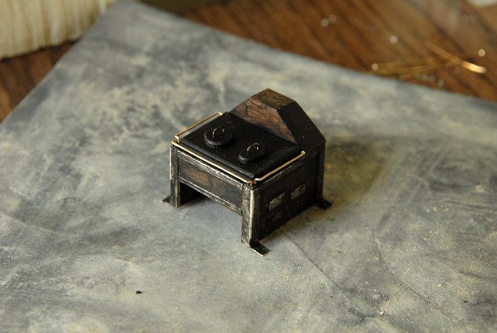
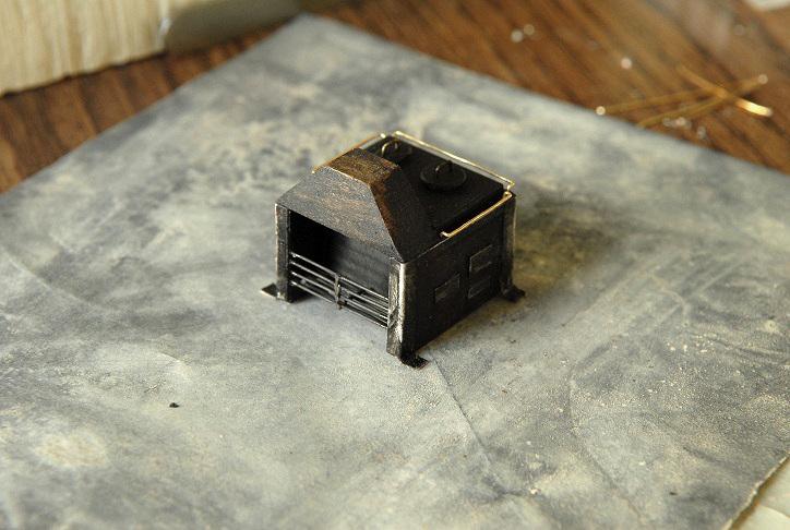
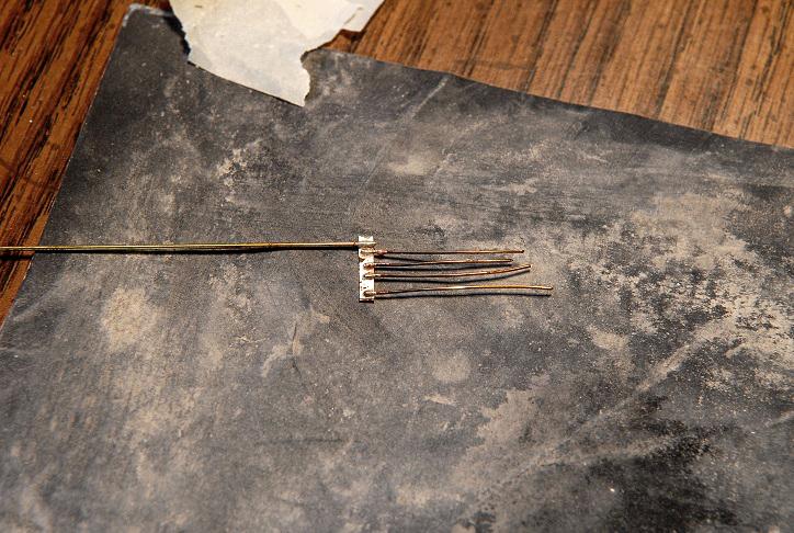
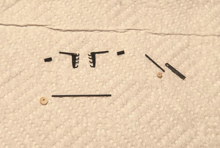
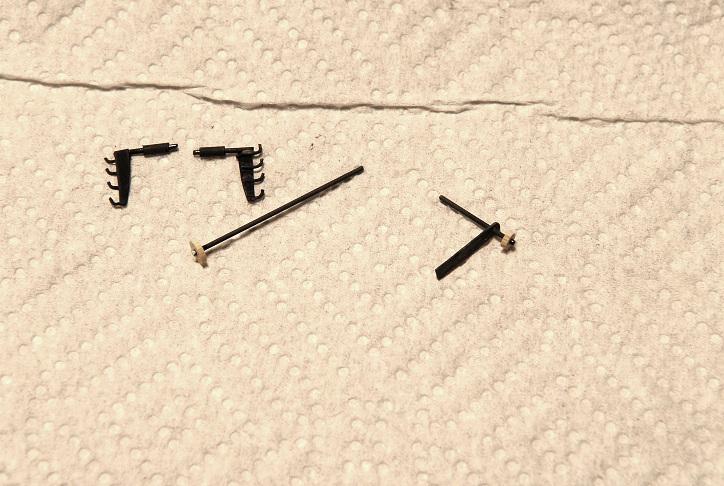
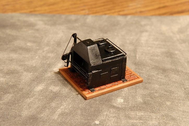
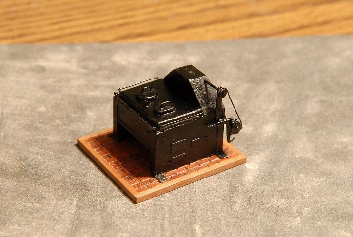
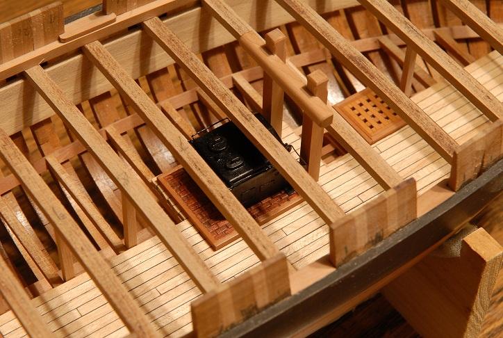
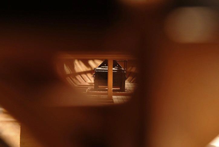
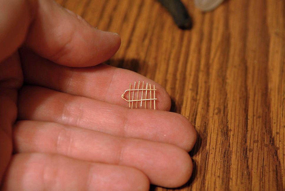
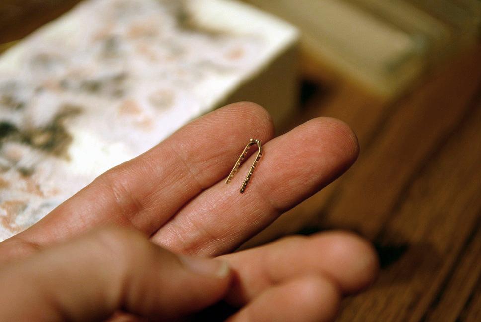
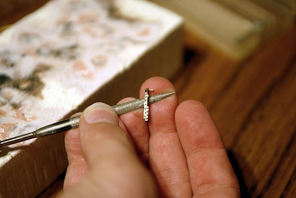
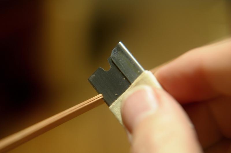
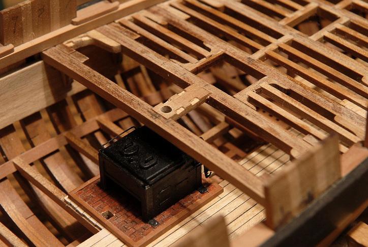
September 11, 2010 continued I use masking tape for everything. And when I need to mask a painted area, I use something else. Haha. So I thought I'd try it for holding pieces to be soldered. I needed to make a little railing for the stove-- The masking tape lasted long enough, and the piece looked okay-- However, I was a little out of practice. Only two pieces joined-- Attempt No.2 was not much better-- Three pieces-- Third times the charm (vs. three strikes and you're out)-- Here it is cleaned up a little-- I realized I needed a second grate, spaced closer together, so here's my setup for that one-- I used more solder and longer heat-- And there are my two gratings-- I blackened them and glued them in place-- Fun stuff!! On earlier pictures of the stove you may have noticed a rail on the starboard side of the stove. It was one of three that go around the top of the stove to hang cooking apparatus from. (Actually it should be a single rail with multiple supports, but making three separate ones seemed like it would be easier) My first attempt was just a simple "staple" bend, which wasn't quite right, so I redid that one, and added the others. They look complicated, but it's really not hard. First the staple bend-- Tested for correct width in the holes I drilled on the stove-- Next the "offset" bend at 90 degrees, one end-- Then the other-- Then this is tested on the stove again-- And if it looks good, trimmed shorter-- And put on the stove-- I almost want to leave those rails unpainted, but that's probably wrong. I also think I may stop the detailing at this point. I'm in danger of getting carried away and making pots and pans. I am still considering whether or not to do the rotisserie--I'm leaning toward not. The stackpipe will come later, when I am working on the main deck. Since this photo, I have put another coat of paint on. When it's dry, and I blacken those rails around the top, I think that will be it with the stove for now. September 12, 2010 This is the start of the rotisserie [changed my mind!]-- Here are the all the pieces after blackening-- The "gears" are sliced from the tapered tip of some throw-away chopsticks-- The stove paint is still drying, so I have to wait to glue the rotisserie on to the stove. September 15, 2010 My Brodie stove is finished-- I like the sheen of the paint--though it will probably dull down as it's not completely dry yet. Overall I'm pleased with the stove. It's just too bad that when the deck is planked, it will be allmost completely hidden away! At least I have the pictures-- [Next photo is from a later post, but it sums up the stove chapter. This is looking through the open lower transom framing, and that's just about the only place you can actually get a view of the stove!]-- Ron