
HOLIDAY DONATION DRIVE - SUPPORT MSW - DO YOUR PART TO KEEP THIS GREAT FORUM GOING! (Only 24 donations so far out of 49,000 members - C'mon guys!)
×


rlb
-
Posts
655 -
Joined
-
Last visited
Content Type
Profiles
Forums
Gallery
Events
Everything posted by rlb
-
 My Oneida has been in limbo for far too long. Thank you Daniel, Guy, Hamilton, Wayne and Adrieke, for your comments, as I have been AWOL. Eventually I will work on the model again. Again, thanks. Ron
 -
Thank you very much for the Birthday wishes Anja! Ron
-
Don, There was one frame, I do not recall which one, that was just as you described, and had to be trimmed short. It confused me at first also. Glad to hear you are making progress. Thanks, Christian. I have not been working very hard on my Oneida. I have sporadically been working on turning out the belaying pins, and I do hope to have an update before too much longer. Ron
-
Fairing a Hahn POF hull
rlb replied to butch's topic in Building, Framing, Planking and plating a ships hull and deck
Thanks for the shattered glass tip, Gary. I never would have thought of that! (Do not attempt this at home. Stunt was performed by an advanced modeler in a closed workshop.) As you can infer from the previous posts, this is a part of the build that many have come up against without a pre-ordained answer, and they've discovered what works for them. There's probably no single best solution. I primarily used a "sanding sled", a shaped piece of wood with sandpaper glued to it. Ron -
Michael, add my admiration to all the others'. It's a joy to watch you figure out each successive piece of the puzzle. Ron
-
Don, no problem with the questions. I did not make any marks or guidelines on my building board. The forward cant frames just about butt together where they meet the keel, and I transferred some marks from the plan set to the keel for the spacing of the aft cant frames. There are some photos of this in my log on page 3, scroll way down to post #39. I will echo to you some advice that Elia,(who also built an Oneida model) gave me. He suggested making some kind of jig to get the bow shape correct. I didn't make a good enough one, and had some problems. I also suggest doing this for the stern, because mine turned out a little narrow. A piece of wood cut to the correct hull shape, held vertically off of the building board at the bow and stern would be a good idea. You can see examples of this on other logs--off the top of my head I don't remember which, but check out a bunch of the scratch build logs--you'll get the idea. Ron
-
Welcome, Scott. Good luck your new "start". I'm personally not a big fan of CA. I used it for parts that wood glue wouldn't work on for my first model, but currently, for metal, plastic parts, I'm finding I like epoxy better than CA. For all porous materials, wood, paper, etc., I greatly prefer PVA (I use Elmer's regular white glue). Ron
-
Keith, that sounds like a pretty useful glue. Don, I think this might be what I was suggesting--it's on Lowe's website, but I don't know if it's available locally for you. There's also a thread that was recently started here: http://modelshipworld.com/index.php?/topic/1894-glue-recommendations/ That might give you more ideas. Ron

-
Hi Don, I am using regular Elmer's white glue, and have had no strength problems at any time. As Titebond 2 has a distinct yellow color when dried, you might consider using their white/clear version, or Elmer's, just to avoid any visible patches of color. Ideally, any dried glue on a visible surface would get sanded off, and nothing would ever show, but I wouldn't be comfortable taking that chance! Ron
-
Hi Don, I wish you good luck with your Oneida, and I hope your cateract surgery was sucessful. I don't think I needed to sand the keel or keelson narrower, they were pretty close to what it seemed they should be. The frames are another story. Taking off 1/16th (after assembling them) seems about right, but it might vary from kit to kit. I just measured a few of my frames, and they measure .325 inches, which is about 15.6" in scale. I'm not sure what they started out at. Rubber cementing the frame drawings onto the frames couldn't hurt. I think you will find that there will be excess wood on the frames, which will need to come off during fairing. I encourage you to start a build log! It would be nice to see another Oneida taking shape. Ron
-
Congratulations, Michael, on your birthday. I'm envious of your retirement. Your metalwork, as with everything, is beautiful. Ron
-
Robert, In Charles G. Davis' book The Built-up Ship Model, he writes "[the pin]rail would be ... 9 inches wide by 3 inches thick. It would be fastened to the inner rail stringer, just above its lower edge..." The book is about the building of a model of a 16 gun brig of similar date. In another part of the book he shows a cross section, with the pinrail and the channels directly opposing each other on the bulwarks (at the same height that is). On his cross section the channels and pinrails seem to be 4-6 inches below the cap rail, but in photos of the model, (and the profile plan) they are right on the underside of the cap rail, and that seems to be what I often see for this size ship. Hope this helps, Ron
-
Thanks, Brian! Ron
-
Welcome, Chad! Glad you are joining us on the site, and thank you for the kind words. Ron
-
Thanks, Russ. 1/2 the diameter just happens to be about what the thickness of the jig is now--I can file the brass ring down if it needs to be thinner. I'll have to do that when I make a jig for the smaller (1/8") deadeyes. Keith and Patrick, I take no credit for the jig. It's directly from Harold Underhill's Plank on Frame Models v.1. I need to remember to look there first when I'm not sure how to make something! Ron
-
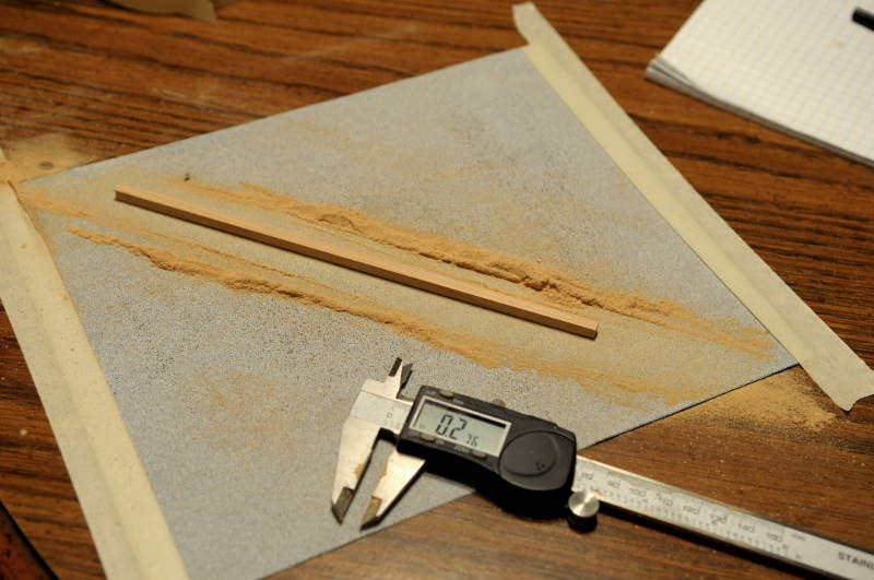
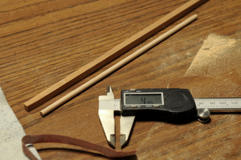
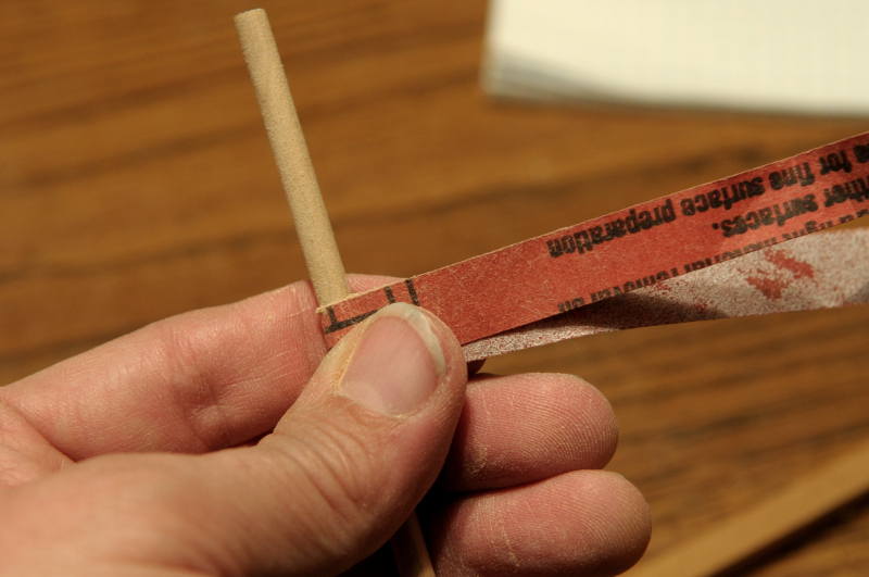
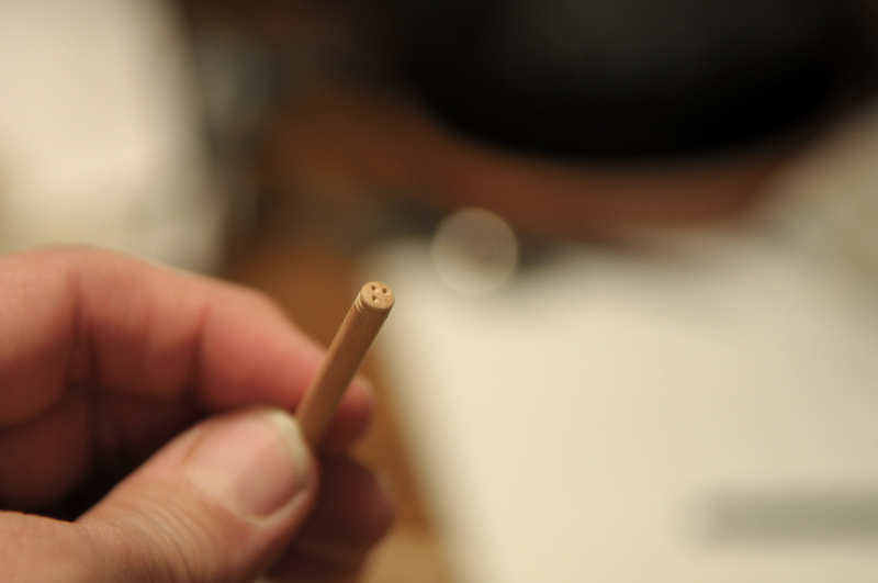
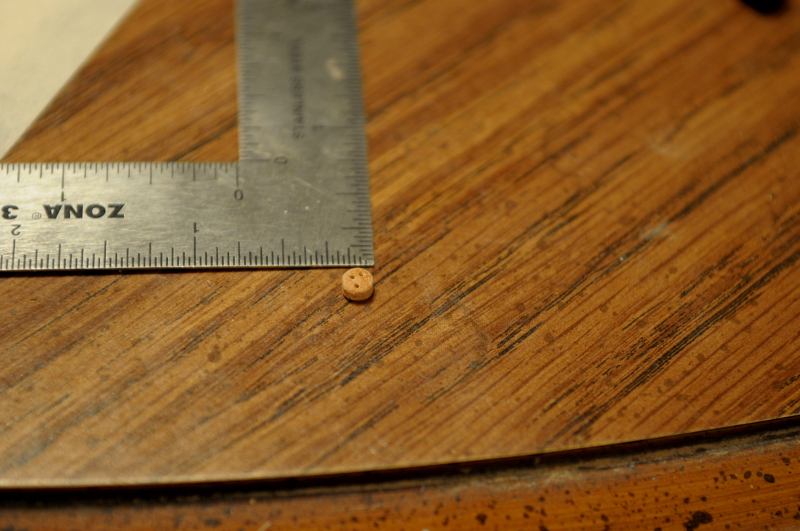
I set about reducing a square cherry piece to a dowel for the larger dead-eyes. The piece was a little over 1/4" square--9/32" to be exact. I needed to get it down to 3/16". This was done all by sandpaper. First sanding it square down to just a hair over 3/16"-- Then, sanding at a 45 degree angle on the 4 corners of the square, creating an octagon. Then just twisting the piece in a loop of sandpaper until it was round. I used 80 grit, then 160, and finally smoothed it a bit with 320-- (The caliper in this picture was set to millimeters--it shows just under 5 mm) Yes, it took a long time, but I was in no rush. Then I used the jig, drilled the holes and roughed out a deadeye-- I'm not sure how thick to make the deadeyes. I need to work with the shroud line, and chain links to determine this. My short list of the next steps is--(1) finish my experimentation on how to make the deadeyes (I don't necessarily need to make them all yet, just settle in my mind how I'm going to do it). (2) experiment with making belaying pins, (3) make the pinrails. Ron
-
Thanks, Elia. You and Russ have persuaded me to try and work with the cherry stock I have, rather than whatever the dowel was made out of. Ron
-
Thanks, Russ. I have some pieces of square stock in cherry that I might be able to use. Color-wise, the type of wood doesn't matter as I plan to paint or stain the dead-eyes black. The square stock is pretty oversize (it's about 1/4 or 5/16"), especially for the smaller of the dead-eyes I'll need. But I don't need much. About 8" of length will supply the 3/16" size dead-eyes, and I may need even less for the 1/8" size. I don't have a way to rip wood, but for these pieces I think I can sand it down, and then I'll look at buying a screw gage to draw it round. If none of that works, then I can go back to the dowels. I'm happy with the jig. I can experiment with cutting the blanks for the dead-eyes first and then drilling the holes--in which case I could use my rotary tool "drill-press"; or continue completely by hand a la Underhill. Ron
-
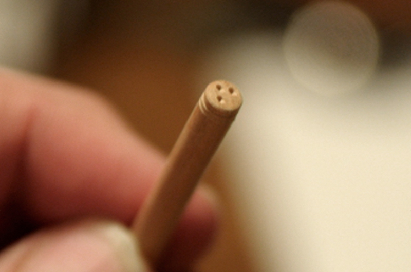
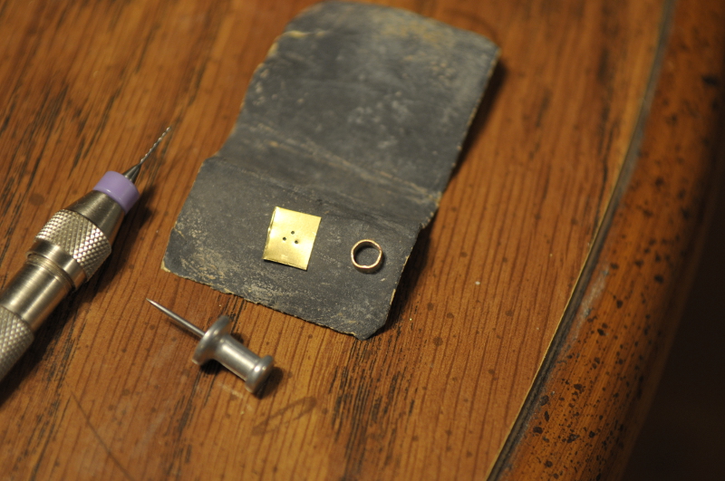
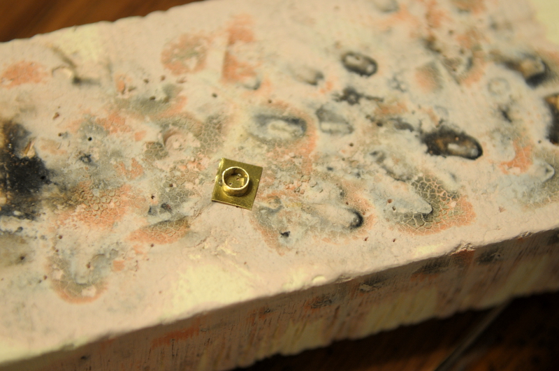
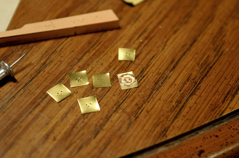
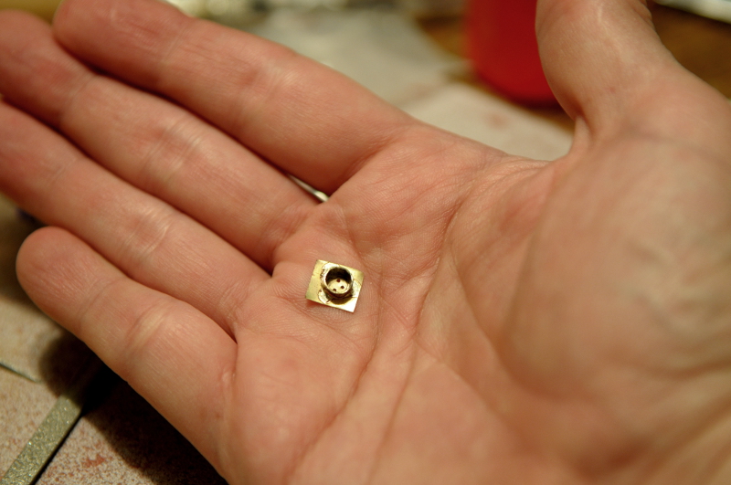
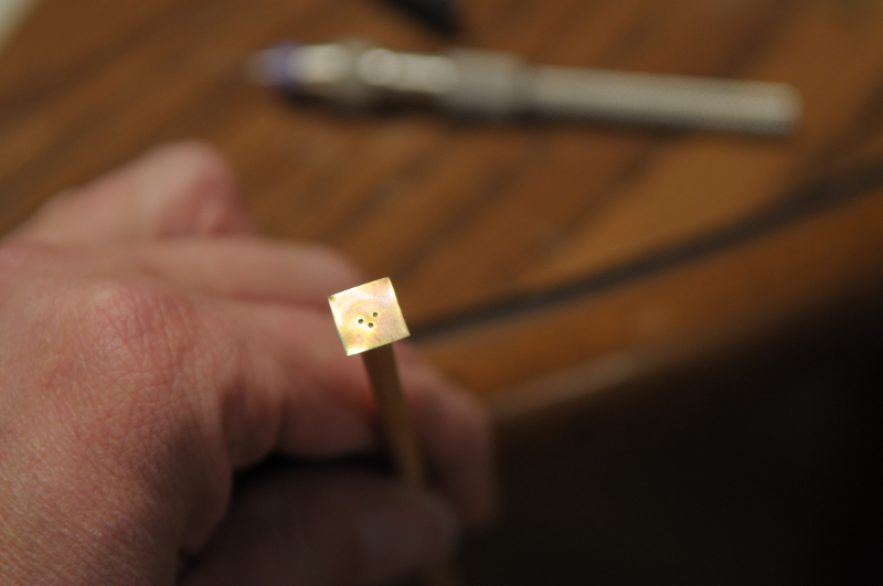
I'm jumping around a lot currently. I have a back-log of things I want to work out. With each little task, though they're not directly related or in order, I feel like I gain some knowledge that might help dissipate some of the "fog" that lays ahead, and make the way forward clearer. That probably sounds overly dramatic, but I'm really slowly feeling my way at this point. I'm pretty happy with how it's turning out! but there is trepidation. Some of the things I've been concerned about for a long time. Like the dead-eyes. The fact that I didn't have an answer for them was weighing me down a bit. My problem was that, in seeing the web site photos from a lot of supply places, the holes aren't really in the right places on the dead-eyes. They shouldn't really be an equilateral triangle in the center, at least from what I've learned about a ship of my era. But even if that was the desired location, the variation from piece to piece looked pretty bad. On the other hand, I've seen fantastic examples on here of folks making their own with great results. But they all have lathes, and precise equipment. What to do? Then, today, I saw Russ' post in his cross section log, and the light went on. In making his dead-eyes he used a jig based on Underhill's, and though I own the book, I hadn't though to look at it. I have now, and the technique is do-able. I have a couple of pieces of old dowel in my wood supply, that I hadn't measured. I'm not sure what kind of wood they are, but lo and behold they are the two sizes that I need for my dead-eyes. The dowel for the larger size isn't perfectly round, so I'll have to figure out if I can deal with it, or whether I need to buy more. But it's good enough to practice on. First comes some brass fabrication: a ring of brass strip made to the size of the dead-eye. And a brass "plate" with the guide holes for drilling the dead-eyes (for the plate I used some thin brass sheet that could be cut with regular scissors)-- They need to then be soldered together-- My first attempt didn't quite make it. The holes, though nicely symmetrical, were not close enough together. I unsoldered the ring, and a process of slow refinement took place. After six or so tries to get the right spacing, I settled on the piece on the far left-- Soldering was tricky. Due to my single overhead light and shadows, it was hard to tell if I was putting the ring precisely where it needed to be to put the holes in the right spot. But this version looked good-- The little jig is then simply placed over the end of the dowel, and the holes drilled-- Then the dead-eye's contours are fine-tuned with a file, and it's cut off the end of the dowel. The result was pretty good. The spacing isn't perfect, but I think it's okay-- I learned a few things to improve as I go forward (like making sure the holes are drilled straight through--the back side of my test piece doesn't look as good as the front!), and I need to decide whether to use the dowels I have or maybe something better, but I'm just happy that this looks like it's going to work! Ron

-
Thanks, Russ. The first version must have been a historically accurate variation--I'm sure Chapelle knew his stuff. (Though who knows how correctly I interpreted his drawing.) I do prefer the look of the second version, for which I had more information (in Charles G. Davis) to work from. Ron
-
Thanks for that suggestion, Bob. I do remember seeing John's post on MSW 1.0 on his hand made belaying pins. Also just saw Russ' nice handmade pins in his cross section log. I'm not as confident of my ability or patience to hand-file 100 tiny wooden pins, all alike! I've got some brass rod and tube on order, to give Allan's technique a try. But if it doesn't work out for me, at least I know the handmade wooden ones are a possibility. Ron
-
Thanks, Adrieke! I appreciate your kind words. Ron
-
Wow, Elia. I thought the hack job on my Oneida wale was a little scary, but this looks far more delicate! I can see why you wanted to fix it--everything else looks so good. I hope plan B for the yellow stripe works out well. Ron
-
Thanks, Allan. I checked out your note. Very clever! I will give it a try. Ron
-
Keith, Thank you very much for your post. What a wide range of models, and methods, exists on MSW! I know there is no possible way I could have built my model on my own, even with all the books that are available. To see the photos in the variety of everyone's build logs, and to watch those models evolve before your eyes, is incredibly instructive, inspirational, and actually makes you think you can do it yourself! Shine on you crazy diamond! I only had two PF albums--Dark Side of the Moon (of course), but I also had Meddle. Ron
