

molasses
-
Posts
455 -
Joined
-
Last visited
Reputation Activity
-

 molasses got a reaction from IgorSky in ESMERALDA by molasses - 1/640 - BOTTLE - Chilean Navy Training Ship
Welcome! I decided to post a photo of the port lights.
At this point I decided to leave the drilled holes unpainted thinking that they are a little more subtle by letting the natural shadows "color" the holes. I can easily change my mind. The holes in the lower row are .020 inch diameter (0.50mm) and the holes directly below the deck line are .025 inch (0.65mm). The lay-out of the holes took considerably longer than drilling them. I find with this macro photo (as usual) that I still have a bit of touch-up to do. The photo also shows one of the photo-etch anchors installed back in May. The port side is also done and looks the same. Compare this photo to the one of Esmeralda at the top of this page.
By the way, the cheap hobby drills I used didn't entirely cut through the paint but pushed up a bit of a ring around each hole simulating the ring on the real port lights.
-
molasses got a reaction from IgorSky in ESMERALDA by molasses - 1/640 - BOTTLE - Chilean Navy Training Ship
Thank you for thinking about by problem, Bob, I appreciate it very much. You have a good eye for detail. you saw that the port lights (or port holes, if you prefer) appear to be close to the same diameter as the handrail spacing. The fixture idea seems useful, I may be able to use a variation on it.
I'm not the least bit concerned about the detail around the port lights. They work out at scale to be less than .0005 inch (about the thickness of a coat of paint) above the surface of the hull and don't show in any photo reasonably close to the size of the model. They barely show at even ten times that size and I think I can see them only because I know they're there.
It's just getting all those little dark grey dots uniformly sized and placed that presents the problem. Even on my steadiest day I know free-hand painted dots are not possible; three or four at most, but not 30+ in a row. Perhaps I can uniformly glue small discs with a slow set glue but I would need to glue them to the wood, not the paint, if I want them to stay on when I insert the model in the bottle.
That thought process - and much more - led me to an idea this morning, based on suggestions I received here, and I'm preparing a test piece to try it and a couple variations.
You have "Every build is a learning experience," in your signature. Ain't it the truth!
-
molasses got a reaction from IgorSky in ESMERALDA by molasses - 1/640 - BOTTLE - Chilean Navy Training Ship
Thanks for looking in, Carl and Bob, and for your suggestions. I've looked in on your builds, admire your workmanship and value your comments.
Here's another photo of Esmeralda I'm using for reference to give a better idea of what I need to do with the port lights. I know how easy it is to lose perspective on what is being done after looking at a series of close-up photos; I do it myself after spending several hours working on details through an OptiVisor and a hand held magnifier.
On my laptop display this image is slightly smaller than my model (clicking on the image will bring up a larger one). The model is 3.5 inches x 7 inches (89 mm x 178 mm) waterline to mast heads and fantail to tip of bowsprit. The photo shows why I can't leave off the port lights, how many there are and, in general, the scope of the difficulty of doing them. As you can see they aren't evenly spaced but they are uniformly parallel to the shear line. The port holes can be off horizontally a few thousandths of an inch and no one would notice, but if they vary the same amount vertically they all will look sloppy.
I value suggestions very much. Even if a suggestion seems stupid it may trigger a better idea that will solve the problem.
Thanks again for looking in.
-
molasses got a reaction from IgorSky in ESMERALDA by molasses - 1/640 - BOTTLE - Chilean Navy Training Ship
Welcome back!
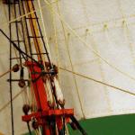
I've been working out how to do two details that I originally did not intend to do but later decided I can't leave out because they are too prominent - handrails and port holes. Here's a portion of one of the photos I've been working with for the deck details.
I needed to make the hand rail (which goes around most of the deck perimeter), anchors, four salute guns and four inclined ladders that go in the "waist" amidship (not shown). I found photo-etch (PE) sheets for all of these in 1/600 scale. I also need to do more than 130 of those port holes.
One of four salute guns.
I have a walk-through video of Esmeralda that shows the brown stocks on the salute guns but the stock got "lost" in the cropping, enlargement and enhancement I did to the deck photo; the stock is the same color as the deck.
I had to modify the PE guns slightly so that they looked more like the salute guns. They're made from two PE pieces plus a piece of brass rod for the cylindrical base.
One of four inclined ladders.
Sorry about the fuzzy photos, it seems that I'm at the limits of what I can do with my camera without buying a macro lens.
The ladders were one flat piece that required bending to form the rails, stringers and steps.
I'm pleased with the anchors and they have been installed on the model. Sorry, no photo yet. As with all the PE parts, I glued the two pieces for each anchor with CA and painted them. Before gluing I cleaned the individual pieces (and my tweezers) with acetone and did not handle them with my dirty, oily fingers at any point during the gluing and painting. Cleaned tweezers only. The pieces and completed assemblies are almost too small to handle with fingers anyway.
I rejected the PE handrails - the rails and stanchions were too fat - so I decided to make them from the 40 and 45 gauge wire I bought. I chose those two sizes because I need to allow for the thickness of the paint so that the finished rails are close to the correct scale size. I made a square frame from some wood, about 2 inches x 2 inches (50 mm x 50 mm) and wrapped the wire around the frame. The 40 gauge was used for the top rail and the 45 gauge for the other two rails and the stanchions. I'm making about twice as much of the rail as I need so I don't have to go through this process twice when I mess up some of the rail - and I know I will.
Close-up of the handrails in progress.
The vertical stanchions are at .100 inch (2.5 mm) increments. The horizontal rails are .025 inch (0.6 mm) apart with an increased space between the bottom rail and the top rail below it to allow room to separate them and trim the bottom of the stanchion for installation. There's another set of rails on the other side of the frame. I put a piece of paper in between so I can see, work on and photograph the rails on one side. Without the paper I simply could not focus on what I was doing. It took several hours getting the wire spacing right. The next thing to do is to glue each of the wire intersections while double checking the spacing. I'm experimenting now with which glue to use.
I admit that I'm kind of stumped on how to do the 130+ port holes. They need to be .025 inch (0.6 mm) in diameter. I'm experimenting with several ideas to find out which gives the most repeatable and uniform results and is not too labor intensive. I'm open to suggestions.
Edit to post slightly better photos
-
molasses got a reaction from IgorSky in ESMERALDA by molasses - 1/640 - BOTTLE - Chilean Navy Training Ship
Welcome back!
After a bit of research for oar details I cut pieces of 32 gauge (.008 inch / .2 mm) wire and flattened one end so it looked something like an oar blade and painted them.
Oars partially painted.
I made four brass painted bits as capstans and fabricated the red and green running lights then glued them in place. After the paint dried on the oars I glued them to the thwarts of the long boats, cut bits of cya stiffened paper as cradles for them and the zodiac and glued the boats in place on deck.
More fiddly bits stuck to the deck.
I also managed to get the green waterline painted.
Close-up of boats.
I find these photos interesting because the magnification is higher than I have with my OptiVisor when I'm doing the work, especially the close-ups.
Thank you all for your kind words.
-
molasses got a reaction from IgorSky in ESMERALDA by molasses - 1/640 - BOTTLE - Chilean Navy Training Ship
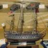
Here's a photo of Donald McNarry's Port Jackson, an 1882 4 masted windjammer. The model is 32' = 1" scale (1/384) and is 11.5" (292mm) long.
Port Jackson 1882, 32' = 1" scale
Here's the link to his website: http://www.facebook.com/l/aAQEzXWhP/donaldmcnarryshipmodels.com/menu.html
I can only aspire to this quality of detail.
-
molasses got a reaction from IgorSky in ESMERALDA by molasses - 1/640 - BOTTLE - Chilean Navy Training Ship
Thank you all for your kind comments, they are very flattering and encourage me to continue to push my limits.
I finished three of the six ship's boats - two long boats and a zodiac. Using the same technique used to make the hulls of the long boats I laid up a partial hull for the zodiac. I bent a piece of .030 inch brass wire as the inflatable portion of the zodiac and trimmed the hull to fit, glued it to the wire, added a transom and outboard motor, floor board and a helm station. I cut floor boards, stern sheets, and made a rudder with tiller and glued them to the long boats then painted them both.
Three of the six boats needed.
I wanted to add the six thwarts to each boat but found that cutting uniform strips .015 inch (.40 mm) wide was difficult and realized that getting them equally spaced and glued in place was going to be even more difficult - if not almost impossible. I then came up with the idea to paint all six thwarts on a single piece of clear .010 inch (.25 mm) plastic and glue the clear plastic in place. Later I'll add twelve oars in each boat cut from 32 gauge wire (.008 inch / .20 mm) with one end flattened like an oar blade, painted and glued to the clear plastic to cover part of the sloppily painted thwarts.
Tired of working on teeny-tiny fiddly bits, I decided to work on merely small fiddly bits, the gaffs and booms for the three fore-and-aft rigged masts. After fabricating them and drilling holes for rigging I painted them and cleared the holes of paint after it dried. The gaffs and the booms are identical on the two middle masts while those on the spanker mast are longer.
Spanker and mizzen/main boom with jaws and a gaff with two halyard bridles and two double thread blocks.
Thread blocks are used to replicate the function and/or appearance of blocks. They are made by tying a knot around the point of a needle then gluing it. I usually tie a left-handed bowline so that the tail comes out the side of the knot, making it much easier to trim, rather than a conventional bowline with the tail coming out into the loop.
By the way, here's a good site about knots: http://www.animatedknots.com/
A double thread block is tied on two needle points. I have a small block of wood with two holes very close together into which I glued the eye end of two needles. The needles touch at the beginning of the tapers to the points. Route the thread around the needle points in a figure 8 with both ends on the lower side of the crossover and tie a half knot there with each end coming out on opposite sides of the "8". Then slide the thread block toward the points to size the loops, bring the two ends from each side over the top, tie a square knot, glue it and slip the block off the points. Trim one end close and the other long (about 1/4 inch so you can handle the block) after the glue has dried. Trim the handle after the block is rigged.
Fixture for rigging the bridles on the gaff.
I think this photo is mostly self-explanatory except for the black thread. It's a loop that holds the middle of the bridles in place until glued. After rigging bridles on the first gaff I found I had omitted a thread that goes through the end hole. The end at upper right will be glued to a hole through the top of the mast, the end at center right will go through a hole at the tip of the boom. The left thread in the tip of the gaff from the bridles will be trimmed flush to the gaff.
Rigging the gaff to the mast.
I'm sure the previous description makes more sense with the gaff in place and the peak halyard rigged. Both threads go to the boom, through the hull and under it to the large hole in the fore deck and out the bottle. The thread to the boom tip is to be glued; the thread through the gaff and boom ends near the mast will be glued when the ship is in the bottle and the assembly is in place and adjusted correctly - the only place it is glued until then is where the end is tied near the top of the lower mast.
Like many model shipwrights I prefer to do as much of the mast rigging as possible before stepping the masts.
-
 molasses got a reaction from ScottRC in ESMERALDA by molasses - 1/640 - BOTTLE - Chilean Navy Training Ship
Welcome to my reconstructed build log for ESMERALDA, the existing Chilean Navy Training Ship, built at 1/640 scale in a bottle.
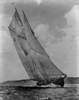
Recent photo of Esmeralda - "The White Lady" - under sail.
History of Esmeralda
Esmeralda's construction started in 1946, under a different name, by Spain as the sister ship to Juan Sebastian Elcano, Spain's current school ship. Work was halted in 1947 after she was damaged in a ship yard explosion. In 1951 Chile acquired her as partial payment for Spanish debts and was launched, as Buque Escuela (school ship) Esmeralda in 1954. In the 1970's her rig was changed from a topsail schooner to a barquentine by replacing the fore gaff sail with two main stay sails.
Since her commissioning, Esmeralda has been a training ship for the Chilean Navy. She has visited more than 300 ports worldwide acting as a floating embassy for Chile. She participated in Operation Sail in New York in 1964, 1976 and 1986, and the Osaka World Sail in 1983. She also participated in International Regattas of Sail in 1964, 1976, 1982 and 1990 winning the coveted Cutty Sark Trophy in the last two participations. Esmeralda is the second longest and second tallest conventional sailing ship in the world.
Characteristics
Length: 113 meters Beam: 13.11 meters Mast height: 48.5 meters Sails: 21 total with a sail area of 2,870 m2 on four masts Crew: 300 crewmen and 90 midshipmen Top sail speed: 17.5 knots
The Model
I acquired a 1.5 liter wine bottle, emptied it (which I enjoyed very much!), then cleaned and dried it. I measured the inside dimensions using a piece of paper attached to a rod, trimming the paper until it would just touch the bottle at the narrowest point.
Gauge for measuring the inside of the bottle.
Gauge in use.
I subtracted the planned sea thickness and clearance for the masts from the minimum inside dimension. I used that amount to determine the model length based on the ship's characteristics and printed a photo to match the model length and height then taped that photo to a rod to test how the model will look inside the bottle.
Photo of Esmeralda inside the bottle. A model this size will fill the bottle very well.
I also cut a strip of paper to the beam of the model to verify the bottle's neck inside diameter. This is important because most necks of long neck bottles have an inside dimension that is smaller than the mouth - something I learned the hard way years ago when I assumed the mouth of a bottle was the smallest part of the neck and my ship wouldn't fit through the neck even though it cleared the mouth easily.
I then generated a deck plan and waterline hull elevation and laid out the plan and elevation on a block of basswood.
Deck plan and hull elevation laid out.
I used a razor saw to make a series of cuts at about 1/16th inch (1.5 mm) intervals to the profile lines on three sides of the block. After getting the rough shape by breaking off the "fins" I sanded the hull to shape.
Hull cut out ready for more detailing.
Esmeralda has a partially open area between the main and mizzen masts which will be detailed with two blocks for the two structures in this "waist" (for lack of a better name) and three pieces of .5 mm ply for bulwarks and deck. I also decided to make and install the bowsprit.
Tapering the bowsprit with my "mini-lathe".
Waist deck houses, bulwarks, weather deck over the waist and bowsprit glued in place.
Esmeralda has a low bulwark (a little less than knee height) at the bow. I made this from a piece of paper slightly lapped over the hull, glued with cya to stiffen the paper then sanded to feather it in to the hull. It was trimmed to .025 inch high (approximately 15 inches to scale).
Completed low bulwark at bow. Note the two holes in the bowsprit for rigging.
Esmeralda has two half rounds running from the bow, along the sides and around the stern parallel to the deck. I used a scribing gauge to slightly cut grooves into the hull which were then deepened slightly with a triangular riffle. A wire or monofilament will be glued into these grooves later then painted over to replicate the half rounds.
Scribing tool.
Hull with scribed grooves mounted on my work board.
I started work on the masts and some of the deck details. The masts have a box hinge instead of the usual piece of wire through the base of the mast bent into a "U" with the two ends glued into holes in the deck. The box hinge will be nearly invisible whereas the bent wire would be obvious. I also made the four identical tops for the masts from .5mm ply sanded to remove one layer of ply (about .015 inch thickness). The skylights were made from basswood painted white glued to a base of .5mm ply painted green. Two hatches were made from the plywood and painted green.
Mast with box hinge and four tops. Drill is a #73
Skylights and hatches.
I finished the rigging plan I'd been working on since making the decision to build Esmeralda.
Rigging plan for the Esmeralda model.
Blue and green lines represent the standing and running rigging that will be completed outside the bottle and aren't used for moving the masts and spars into position inside the bottle. Red and magenta represent the standing and running rigging that will be set up but not glued in place outside the bottle and are used for locating the masts and spars inside the bottle then glued and trimmed.
I laid out the holes for the masts and rigging and started drilling them.
Drilling holes at the edge of the weather deck for shrouds and back stays with a #80 (.35mm) drill.
The holes at the edge of the deck need to be drilled at an angle so they don't come out the side of the hull. I had one hole out near the end of the fan tail that needed to be over 45 degrees from vertical. I didn't quite have the angle right and the hole came out the side of the hull but it was easily repaired, but redrilling the hole from the same starting hole was somewhat difficult. I also had to change to a larger diameter drill because the smaller drill wasn't long enough to drill all the way through to the bottom of the hull.
Close-up of holes for fore mast shrouds and back stays. Holes for main mast shrouds and back stay are visible next to the bulwark in the "waist" at upper right.
Work in general had progressed to the point that I felt getting the sea in the bottle was necessary. I used Fimo Classic modeling clay (a polymer based compound - Sculpey, Pendo and Plasticine are possible substitutes - but Fimo has a navy blue that comes very close to the color of deep water ocean). I formed it into a piece 7 inches by 2 inches by about 1/4 inch thick tapering to zero around the edges to fit into the cylidrical bottle and leave the top surface of the sea roughly level. I then put the hull on top of the clay in the position needed then pressed it firmly into the clay with a steel rod.
Hull pressed into the sea to leave an impression.
The steel rod is 3/16 inch diameter with the end ground, filed and sanded to a hemispherical tip then bent as needed. The gouge is a similar sized dowel with a slot cut in the end to hold a strip of aluminum soda can then wired tight. After determining the needed angle of the gouge by trial it was glued.
After the hull was removed I used the gouge to remove some of the clay from inside the impression of the hull. I used the removed clay to build up a wind swell running from near the near left corner to near the far right corner (replicating the sea with a wind from about 60 to 70 degrees off the starboard bow).
Using the gouge to remove clay from the hull impression.
I put the hull back in the sea, pressed it down, removed it and gouged out more clay until the hull fit snugly in the depression. After that was done I used the rounded tip of the steel rod to cover the surface of the sea with little overlapping dimples except for the ship's wake which was smoothed with the tip.
Sculpting the surface of the sea.
I made one more check of the hull in the depression for it in the sea then added some white Fimo to simulate the agitated white water at the bow, along the sides, in the wake and for a few wind blown white caps. I placed flecks of the white (or a partial mix of blue and white) on the tip of the steel rod to transfer them to the sea then feathered them into the blue.
Finished sea.
I completed basic mast assembly - lower masts with hinges, tops and upper masts - and set them into the appropriate holes in the hull.
Esmeralda in progress on the working board with some of the tools being used.
Then I rigged her with one pair of back stays on the fore and spanker masts, a single fore stay and the mast to mast stay that connects all four masts at the mast splices. This was done in order to do a trial fit of the hull and masts to verify that the completed assembly will fit in the sea with clearance for the masts to stand erect. I calculated my dimensions very closely with about 1/16th inch clearance between the mast tips and the inside of the bottle.
Esmeralda with minimal rigging. The rigging is tied off but not glued. It will be removed after the trial fit.
On a previous build I neglected to do a trial fit on a ship that I had also calculated very closely. I got that ship in the bottle and in place in the sea. I had pulled up the fore mast and positioned all the fore mast yards and had glued most of the fore stays and working lines to achieve this, then moved on to the main mast. The mast tip hit the inside of the bottle before it was in its correct position. I had to cut all the glued lines to get the fore mast to fold back down so I could remove the model. Even at that two fore mast yards snapped because I could not get them arranged the way they were when I put the ship in the bottle. I NEVER omit a trial fit after that experience no matter how confident I am with my calculations.
Esmeralda going into the bottle.
Esmeralda in place in the sea with masts all erect. There is about 1/16th inch clearance between the mast tips and the bottle.
This trial fit also gives me a chance to trouble shoot the insertion process. In this build the deep dimple in the base of the bottle prevents me from simply setting the model in place then erecting the masts. I'll have to start erecting the masts when the bowsprit is still partly in the neck of the bottle. Another good reason to do a trial fit with bare poles and minimal rigging.
Now that I know my masts are all correct it's time to detail them. I made some ring bolts out of 32 gauge (.008 inch) wire by bending the wire around the tip of a needle, forming the two ends next to each other then cutting the ring bolt from the length of wire. I had so much fun doing them I made 25 of them before I realized I only needed 12.
Ring bolts.
I made the fore mast yards, drilled the holes needed in all the masts and yards then painted them. I decided that I could make use of the extra ring bolts by linking two of them together, eye to eye, to use to connect the yards to the fore mast. I glued one ring bolt in a hole in the center of the yard then glued the other linked ring bolt in a hole in the mast. After that I rigged the topmast shrouds, three pairs on the fore mast, two pairs on the other three topmasts.
Rigging the fore topmast shrouds. Note the linked ring bolts connecting the yards to the mast.
I also added an extra ring bolt to the forward edge of the top on the fore mast to use to tie off the two fore stays that start there. After rigging the topmast shrouds I glued a crossbar of thread to the shrouds about 1 mm above the top. I painted the threads from the crossbar to the top white to simulate the turnbuckles used on Esmeralda instead of deadeyes and lanyards. The futtocks were painted to match the masts.
Masts with completed shrouds.
I then rigged the fore mast yards with one thread through each yard end, through the mast then through the other end of each yard. The two ends terminate with a thread block - in this case a bowline tied around the point of a needle then glued - to simulate a block used in the actual rigging of Esmeralda. The only place where the thread is glued is at the course (lowest) yard which allows the yards to turn so they are nearly parallel to the mast so the assembly (with sails in place) will pass through the bottle's neck.
Foremast with some of the running rigging. Note that the linked ring bolts merely locate each yard.
I worked on the hull as well by gluing 28 gauge wire in the previously cut grooves in the hull, installing four ring bolts on each side of the bow and rigging the bowsprit stays. Then I gave the hull the final coat of white and glued the deck details that were ready in place.
Some of the deck details installed.
I then painted the figure head - an Andean Condor.
Close-up of figure head and bowsprit stays.
This brings us up to date on my progress reports on Esmeralda prior to the MSW shut down for the software change. In that time work continued on deck details.
Davits for three of six ship's boats, crane for the zodiac, the bridge, two catwalks, four winches and the anchor windlass and associated details in place.
Close-up of midship section.
Davits were made from 28 gauge wire bent to shape and glued in holes in the deck. Crane made from three pieces of wood and styrene. Bridge made from a .5 mm ply base and roof, wood between, with 32 gauge wire legs at the wings. Catwalks from .5 mm ply with eight 32 gauge wire legs glued into holes in the ply and deck. Winches made from two pieces of wood on a ply base.
Close-up of windlass, bits and hawser hole covers.
The anchor windlass was fabricated from eleven pieces of .010 and .020 inch styrene and three pieces of wood on a base made from paper stiffened with cya glue. The windlass isn't glued down yet. That will be done inside the bottle to cover a hole through which six lines pass after they are glued and cut. You may have noticed two threads coming from under the green covers. They will be used to pull the two chain ends into place during the windlass positioning. The chain is copper, 42 links per inch, blackened with the product from Model Expo. I know it's a bit over size (by about 50%) but I could not resist putting it in.
With davits on deck I need to make some boats: two longboats, two smaller boats similar to old whaling boats (pointed bow and stern, narrow beam), a zodiac and another power boat similar to a modern Boston whaler. I haven't seen this boat in any of the photos of Esmeralda I've found, I may just have to make my best guess and wing it. I can infer the length from the davits and the beam and length from Esmeralda's deck plan which shows the outline of this boat on deck but nothing more.
I started with the longboats. I made a plug from basswood, dipped it in warm paraffin wax (so glue wouldn't stick to it) and wiped away the excess wax. After attaching it to the tip of an Xacto knife I covered the plug with narrow (less than 1 mm) strips of wet newsprint laid lengthwise, edge to edge, like planks. I painted a layer of thinned wood glue over that layer then added a layer of wider strips laid across the plug, again edge to edge with another coat of thinned glue over it. After the glue thoroughly dried I lightly sanded the outside of the paper hull then trimmed the overhang flush to the plug. It popped right off the plug at that point. The second longboat hull is drying now.
Longboat plug and hull.
Now that I'm all up to date I'll end this report. I welcome any comments and questions.
Edited title of topic to reflect a change to my display name.
-
 molasses got a reaction from GrandpaPhil in OGALLALA by molasses - FINISHED - 1/96 scale - BOTTLE - Prairie Schooner
I'm posting a follow-up on Ogallala.
Upon finishing her I submitted photos to Bottle Shipwright, the quarterly journal of the Ships in Bottles Association of America (of which I am a member), and quickly learned that Ogallala would be the featured SiB in the March issue which I received a few days ago. Here's the cover. I'm not going to bore you with posting the photos from the article because they have already been posted here.
As an aside, I mentioned a couple times in this build log that I can't really see my work for what it is. All I can see are the deficiencies no matter how minor. Ogallala has been sitting in a box on a shelf since I finished her in late October - until today. I'm now able to see her as a whole and I'll admit I was impressed and very pleased.
If you haven't seen them yet check out my two current projects listed in my signature.
-
 molasses got a reaction from Mfelinger in OGALLALA by molasses - FINISHED - 1/96 scale - BOTTLE - Prairie Schooner
I'm posting a follow-up on Ogallala.
Upon finishing her I submitted photos to Bottle Shipwright, the quarterly journal of the Ships in Bottles Association of America (of which I am a member), and quickly learned that Ogallala would be the featured SiB in the March issue which I received a few days ago. Here's the cover. I'm not going to bore you with posting the photos from the article because they have already been posted here.
As an aside, I mentioned a couple times in this build log that I can't really see my work for what it is. All I can see are the deficiencies no matter how minor. Ogallala has been sitting in a box on a shelf since I finished her in late October - until today. I'm now able to see her as a whole and I'll admit I was impressed and very pleased.
If you haven't seen them yet check out my two current projects listed in my signature.
-
molasses got a reaction from Mfelinger in OGALLALA by molasses - FINISHED - 1/96 scale - BOTTLE - Prairie Schooner
Thank you Keith and Omega and to all the 'likers', you're very kind.
I started by wiping down the entire inside surface of the sphere to remove any debris from the base assembly. The rigging on many lines on the ship were slacked off, masts hinged down to the deck and the two big sails extended part way away from the ship and rolled to go in the bottle. The mainsail was rolled and started into the opening followed by the main masthead, fore masthead and then the transom of the hull. This was the tightest spot, then I had to adjust the fore topsail yard and crossjack as they slipped through.
Part way in and looking good, no problems yet, even though the rigging looks like a rats nest again but
it's more like organized chaos and will restore most of itself as the masts hinge back up.
When I got the ship a little further in I started raising the masts and pulled the fore mast into its position, tied off the forestay at the bowsprit and glued it, then did the same with the jibstay. I turned the ship over, tensioned the mainstay and glued it where it comes through the bottom of the hull.
Upside down, held in place so I can trim the two ends of the mainstay. Next step is to turn
the ship back over and glue it to the lower hull.
Upper hull turned over and glued to the lower hull. The crossed poles are bamboo skewers cut
off about 1/8 inch / 3 mm out the opening with a lead weight on the ends while the pva cures.
The three stays are the only lines that I've touched so far; more to go but the worst is over.
From here all that's left is several tedious hours of adjusting about twenty more lines, then securing and trimming them. One thing about working inside a sphere I like a lot is that I can turn the model so the part of the ship I need to work on is near the opening - something I can't do inside the usual, cylindrical bottle.
Dave
-
 molasses got a reaction from dgbot in OGALLALA by molasses - FINISHED - 1/96 scale - BOTTLE - Prairie Schooner
Don't hold your breathe you'll just pass out. I do enough holding my breathe for everyone just to help keep my hands steady. When working with the very small I can sometimes see my pulse transferred to the tip of a tool.
I started by making and inserting a cone of waxed paper to protect the glass from smudges from painted surfaces, to protect those painted surfaces and to provide a catch for debris from the prairie segments. Using the clamping tool - I call it a trombone because of its resemblance to one - I assembled the prairie segments. This went so quickly and easily, relatively, that I almost forgot to take a photo.
Three segments of prairie assembled with the wheeled assembles stationed for use a bit later.
The trombone holds the segments together as the fourth is inserted, positioned and slid onto
the three brass rods. The clamp is released from the three segments, opened to hold all four
and then clamps them together.
Using the trombone, the disc was turned over and the segments were glued with slightly diluted pva (about 20-25% water) painted onto the seams. This went very quickly - the photo was taken just 45 minutes after starting and the glue on the disc was drying another half hour later. I had to modify a brush by cutting it off at a slight angle just behind the ferule and gluing it back together rotated 180 degrees to give me a brush with a roughly 45 degree bend.
Getting to this point took more work and fiddling inside the bottle. I used the trombone to hold the
lower hull as the wheel assembles were glued to it. The threads kept getting in the way and I had
to keep in mind that I had to turn this assembly over. I had to take it apart once to get the lines right.
I used a model railroad scenery glue - Hob-e-Tac from Woodland Scenics - to assemble these three pieces. When spread on a joining surface and allowed to dry until clear (the glue is white) it acts like a contact adhesive. This glue isn't as aggressively tacky as contact cement and gave me time to get these pieces assembled. I used long tweezers and a pair of bamboo skewers, manipulated like chop sticks through the bottle opening, to get the wheels attached to the lower hull. This assembly took another hour and a half.
The trombone was indispensable to both of these assemblies. It is rather simple and an improvement over one in my toolbox.
The trombone clamp relaxed. The rubber band is the spring that provides clamping
force and is easy to replace with shorter, longer or stronger bands when needed.
The clamp holding a triangle to show how it works.
The clamp disassembled. The small brass pin keeps the ends aligned. By making brass tube pieces to fit in the
three vertical tubes the clamp can be easily modified to hold irregular objects. The small piece of tube with one
end deformed so that it is a slight press fit in a larger tube is just an extender. The older version was essentially
half of this with just one outer tube with a stop and an inner tube like one of these but it would not hold larger,
irregular objects. Shrink tubing can be shrunk around the clamping points or the points can be wrapped with
masking tape for finish protection.
The next step was to glue the wheels of the lower hull to their places on the prairie. I slowly worked the wheels into the wheel tracks using the threads from the wheels and a tool to apply downward pressure from above. When the wheels were near their position I moved the waxed paper and disc until the bottle opening was on top and the paper and disc were on the bottom. I applied large blobs of pva at the wheel attachment points, allowed the waxed paper and prairie disc to slide over the opening as I slowly turned over the sphere, routed the threads from the wheels through the opening and pulled on those threads until the wheels were well embedded in the glue. Much of this latter work was done on an impromptu stand to allow access inside the sphere from below. I then attached clothes pins to the four threads to provide weight to hold the wheels in place while the pva cured.
The impromptu stand made from soda cans, a piece of wood with a hole in the center
and a piece of card stock all glued together. I need to make a more permanent version.
Lots of clothes pins were used to weigh down the wheels into their places.
Seven components assembled inside the bottle / sphere. Look familiar? This part took about two
hours. I left the weights in place over night and all the next day before moving on to the ship itself.
It took about five hours total, all in one day, to get these components assembled not counting breaks for photos, food, glue setting and my nicotine addiction. The clamp allowed the work to progress rapidly - combined with sufficient assembly practice outside the bottle to find and eliminate potential problems.
Now for the last component.
Dave
-
molasses got a reaction from dgbot in OGALLALA by molasses - FINISHED - 1/96 scale - BOTTLE - Prairie Schooner
I am working on a display base, nearly complete, and have had the mast folded down and back up again, twice, as dry runs to identify and adjust for problems with the lines before putting the ship into the bottle. On one of those dry runs I passed the ship through a ring slightly smaller than my bottle's neck to verify that it will fit - a must do to prevent the disaster of getting the ship stuck in the neck.
I've just about given up on making and installing coils of rope on the pinrails and cleats. I made a fixture for making some coils - which turned out okay - but I found them very difficult to install in many places. I should have made and installed them as I tied off each line instead of as a separate step. I may try again starting with the easy ones to get to instead of the hardest ones.
I received the Micro-Mark Pro-Etch Kit and set out on the learning curve - which is rather steep to successfully make usable photo-etch parts on the first try. It took me three.
After ordering I set about drawing in my drawing program the etched letters I wanted on two brass discs - one as a seal for the bottle and one on the display base. Keeping it simple, I planned to remove lettering on one side of the discs that I would later fill with paint, black letters on the brass discs. When the kit arrived I read the instruction book multiple times and identified all the tools and materials in the kit.
Following the instructions, I made the masks for both sides of a disc and printed them on the backside of the mask transparency film. Follow the instructions carefully. The black areas of the mask are the areas that need to be removed from the metal and this mask will be printed backwards (flipped horizontally) so that the print is on the backside of the film. After the ink is dry the two masks are perfectly aligned, print side to print side and taped together.
The print side of the mask transparency. The face side of the disc with reversed
lettering and the back side with interruptions in the circle so that the disc will stay
partially attached to the square of base metal. The black is what will be removed,
half-way through from both sides with most of the edge all the way through.
With directions in hand I cut two 2.5 inch / 64 mm squares of .005 inch /0.13 mm thick brass sheet. Before I opened the package of photo-resist film I set up a darkened work area lit by a single yellow "bug" bulb, then opened it, removed the resist and cut two squares, put them in an envelope lined with black paper, and returned the photo-resist film to its package and sealed it shut. This film hardens in UV light. I prepared a brass square by wet sanding each side of the square with a provided 3200 grit sanding pad until very shiny and so that the water sheeted across the square. I pulled one piece of the resist from the envelope, peeled off the inside cover film and, like applying a decal, attempted to lay the resist film on the wetted square, get it aligned to the edges of the square and adhered to the square without bubbles of air or water between the film and the brass. This turned out to be rather difficult and I had problems with it. On my second through fourth tries I submerged the brass square in just enough water to cover and applied the resist film through the water. (An old school decal application trick.) I did the same to the back side.
While doing this I had the Pro-Etch laminater plugged in and warmed up. I cut two squares of carrier sheet (card stock with one side treated so that it is glossy and smooth) slightly larger than the brass squares. I made a sandwich of the photo-resist covered brass square with the two squares of carrier, glossy side to the photo-resist and ran it through the laminater twice, flipped over and turned 90 degrees for the second pass and let it cool in a black envelope.
Next the cooled, laminated brass square (carrier sheets set aside) is slipped between the two masks and centered, then placed in the center of one of the Plexiglas squares provided, the other Plexiglas square placed on top and clamps applied at the four sides. All of this has been done with minimal exposure to UV light, just the yellow "bug" bulb - a suggestion in the directions.
Again per the instructions I exposed each side of this sandwich to full sun at local noon for 20 seconds. The UV light hardened and turned the photo-resist in the areas not masked a deep blue from its original light blue. I disassembled the sandwich and returned the brass square to a black envelope while I set up for the next step and put away what I wouldn't need right away.
I prepared a solution of sodium hydroxide and water per the instructions, removed the outer protective layer of the photo-resist film from both sides and submerged the brass square in this solution. This chemical reacts with the masked and un-hardened photo-resist film, softening it so that it will brush away. This is the most important part of the process, if the film is not completely removed from the areas to be chemically etched it won't etch properly. This is where I messed up in my first two tries; for the third and fourth tries I used my 2.75X Opti-Visor and inspected and brushed with the solution and inspected and rinsed and brushed some more until I was certain that every bit of resist was removed from the areas that needed to be etched. I made use of a hand held magnifying glass with the Opti-Visor to make sure every bit of un-exposed resist film was gone.
The second brass disc with blue photo-resist and bright brass showing through the
areas that will be etched. I thought this was good enough but it was not. Many areas
did not etch properly, especially from the backside, due to my lack of diligence.
Paying close attention to the instructions, I set up the equipment for the actual photo-etching. I had to supply a rinse bucket and a smaller rinse bowl, both filled with water. I warmed the bottle of ferric chloride in hot water running from the tap before filling the etching tank. I plugged in the aerator (to circulate the etching solution) and submerged the brass square. I set a 5 minute timer.
Etching in process. There's a clamp on the hose to prevent the etching solution from
flowing back into the pump plus the pump is placed on two pieces of foam packaging
to raise it above the solution level.
After five minutes, I removed the brass square from the etching tank (turned off the aerator and pinched shut the hose clamp - the fumes must be assumed to be nasty) rinsed and re-rinsed to inspect the progress. Most of the double side etching at the edge of the disc was cut through, so I turned the brass square 180 degrees in the clamp, returned it to the solution (turned on the aerator and released the clamp) and waited three minutes. Upon inspection, it was done and I rinsed it in hot tap water before setting it aside and cleaning up.
Now, to see the results. I poured out just enough of the sodium hydroxide (undiluted this time) into one of the trays provided to cover the brass square. Full strength this chemical removes the photo-resist from the brass with a little help with a brush. When cleaned of the resist the brass was rinsed in hot water from the tap and set aside.
Here's my first try with some practice with black enamel to fill in the letters. There are
several places where the photo-resist did not adhere and laminate properly as a result
of my difficulty with getting the resist in place as directed and etching solution got into
them from an edge exposed to etching solution. I had no more problem with this using
the submerged technique of applying the photo-resist film. Many places in the lettering
have incomplete depth because I didn't get all the masked film removed the way I should
have. Micro-Mark was right when they said this was the most important step.
Third and fourth tries, both appear perfect. The lettering has not been filled with enamel
yet, just the result of better photographic technique learned since the photo of the first
disc. I didn't even bother stripping the second attempt since I could see that I had not
removed all the masked and un-hardened photo-resist film. The discs are 1.73 inch / 44
mm in diameter.
I am very pleased with the Micro-Mark Pro-Etch Kit. It has everything needed except for a yellow "bug" bulb and the two rinse buckets I provided. I bought a better pair of rubber gloves than the single use, throw away gloves supplied in the kit for my second session when I made the last two discs. I also added a small in-line on/off switch to the aerator electric cord so I would not have to crawl under my work bench to unplug it when I needed to turn it off.
The process does have a steep learning curve, a mistake made anywhere in the process will affect the results. READ AND STUDY THE INSTRUCTIONS and MAKE SURE YOU UNDERSTAND EACH STEP.
I hope my experience helps others learn from my mistakes.
As you can see from my name plates I've set myself a dead line of the 29th of this month - one year from my first post for Ogallala. A year is long enough and I'm getting tired of looking at it.
Dave
-
 molasses got a reaction from Chasseur in Preussen by Chasseur - BOTTLE - barque
Life does tend to intrude on one's hobbies, doesn't it?
-
 molasses got a reaction from captainbob in Preussen by Chasseur - BOTTLE - barque
Life does tend to intrude on one's hobbies, doesn't it?
-
 molasses got a reaction from cog in Preussen by Chasseur - BOTTLE - barque
Life does tend to intrude on one's hobbies, doesn't it?
-
molasses got a reaction from IgorSky in OGALLALA by molasses - FINISHED - 1/96 scale - BOTTLE - Prairie Schooner
Welcome.
Spent several hours on the computer redrawing the sails based on my card stock templates made to verify size and curvature then detailing the drawings with seam edges, stitching, patches, reef bands and brass colored grommets. I then mirrored those sails and detailed the opposite sides to match.
Sail printing computer master. I used four shades of light grey and two shades of light tan to simulate
differing ages, thicknesses and production lots of the canvas. This image was printed on both sides of
a sheet of paper to print two sets of sails. The red crosses and the blue centerline and border served
as register marks to check that the images on both sides align to each other. I stopped counting at
about twenty tries and estimate that it was at least thirty print-outs before I got one sheet with two sets
of sails where the variables in paper feed starts, slight angular shifts of the paper during printing, etc.
resulted in one "perfect" set of sails. I used the best grade of 20 lb. printer paper with the smoothest
surface finish I could find.
After cutting out the sails I drilled the holes at attachment points rather than poking holes with a needle point which promotes tears in the paper near edges. I also drilled the holes for the reef point ties.
Fore topsail bent to the yard with the reef point ties in place and the buntlines finally rigged.
Notice the stitch line below the reef band across three clothes for the wear patch on the other side.
The sail is 2.015 in X 1.140 in (51 mm X 29 mm) since I forgot a size reference again.
Aft side of the topsail. Here you can see the wear patch in a slightly darker shade of gray,
a buntline and a clew line with an appropriate caternary to the corner of the sail.
I made up some blocks at .032 in (0.8 mm) diameter for some of the sail control lines on the staysail and jib and bent the sails to the stays.
Jib with a block and rope for the downhaul. I still need to rig the sheets at the corner. The block
and rope for the uphaul is visible just below the stay in the first photo of the topsail.
Dave
-
molasses got a reaction from IgorSky in OGALLALA by molasses - FINISHED - 1/96 scale - BOTTLE - Prairie Schooner
Thank you, Piet and Bob, and the likers and lurkers. I don't mean "lurker" at all derogatorily - I "lurk" several builds and topics myself.
Worked on some odds and ends. I started with some cleats.
Cleats ready to install. They have a piece of bug pin through them for strength when glued to the bulwarks.
Some of the cleats glued into holes and rigged. The crossing ties on the cleats are fakes.
The lines to the cleats will be glued when inside the bottle and trimmed close to the cleats.
Then I finished the foremast yard braces and foresail gaff vangs.
Upper portions of the braces and vangs.
Lower portions of the braces and vangs.
The remaining rigging will be finished when the sails are installed.
I also worked on my trial figure by building it up with some more gesso to the point where I can try to detail it. I discovered that the cured gesso is flexible, almost rubbery, and I can adjust the pose, which may be a blessing - or a problem. I didn't test it to find out how much flexing it will take, maybe later if I don't like the finished figure or replace it with another after some practice making three more figures.
A photo I posted a while back for comparison to the more "filled out" current condition.
A pair from his larboard quarter. I trimmed the legs and will add feet below the cuffs of his pants.
And from his starboard quarter. It seems my photography has improved somewhat in the interval.
Dave
-
molasses got a reaction from Mfelinger in OGALLALA by molasses - FINISHED - 1/96 scale - BOTTLE - Prairie Schooner
Welcome back.
Thank you, Jeff and Michael, you are both very generous. BTW, I proudly stole every one of "my" techniques - thank Donald McNarry and Lloyd McCaffery for many of them.
I started with the breast backstays, each rigged with a single and double block. After choosing the length of the tackle from outside to outside of the blocks I routed the thread between two pins in drilled holes in a scrap of wood and built the tackle using the discs as previously described then needle spliced an eye around each block and added the backstays to the model.
I rigged the main ratlines using a "harp" with ratlines spaced and glued to wooden frames. The frames were opposite hand, one for each side of the schooner. After pinning the frame in position with bug pins I glued all the intersections. I'm trying out artist's matte acrylic fixative instead of thinned white glue and am pleased with the results. The white glue sometimes goes milky while the fixative stays clear. I thinned it a little by using a wetted brush when I dipped it into the fixative.
"Harp" pinned in place with intersections fixed and frame ready to cut from the ratlines.
Starboard side has the harp removed but the excess on the ratlines un-trimmed.
Breast backstay and trimmed ratlines. The backstays go through the same hole where the
topmast shrouds were secured and are now tensioned with weights. The backstays need a
bit of adjustment before they glue. After this photo I rigged the futtock shrouds and
futtock staves then glued and trimmed the backstays.
Starboard view of the mainsail, spars and rigging. While assembling this I had a card stock sail
in place, tied to the boom, mast and gaff to hold them in their correct positions. This card stock
sail has been lengthened slightly along its leech (aft edge) to give the belly I want in the sail. The
aft ends of the boom and gaff have a thread to pull that belly in this temporary sail.
Larboard view. The card stock sail will be removed later to use as a pattern for making the sail.
The black line will be removed before the sail is installed. I have some cleats to make and install
where the leads from the blocks and tackles will tie off which explains some of the stray threads.
Close-up of main top showing the futtock shrouds and futtock staves. I used a needle to pass
each futtock shroud through a lower shroud, glued it (not ca) then passed the needle through
those intersections, sideways, for a third thread to be the futtock stave, glued it and trimmed.
Close-up of main top showing the boom and gaff halliards and gaff throat halliard. After making
and installing the throat halliard and installing the gaff I routed the throat halliard and the boom
and gaff halliards through eyebolts installed while building the masts. The blocks for boom
halliards were made in place. The block on the gaff bridle halliard at the eyebolt was glued
prior to rigging to act as a stop while rigging. All four lines continue to the deck.
Close-up of pin rail where the halliards tie off. I installed eyebolts earlier for the gaff halliards
to route through so that some of the tension on the pinrail is downward to balance the upward
pull by the boom halliards tied off there. Tensions are very light - just enough to hold the line
straight - but I felt it necessary to do this. You can also see where one of the breast backstays
tied off to the pinrail on the bulwark just below the shrouds. A white thread from the throat of
the boom, through the mast and out the bottle for pulling the boom into place is also visible
but mostly out of focus.
I almost forgot a size reference but recovered with a standard #11 X-Acto blade.
As always, click on a thumbnail shown here for the larger format photos.
Thank you for viewing this log.
Dave
-
molasses got a reaction from Mfelinger in OGALLALA by molasses - FINISHED - 1/96 scale - BOTTLE - Prairie Schooner
I've been building ships in bottles for more than 35 years and every one of them has been a waterline model, most under full sail, with the wind direction and strength appropriate for the sails and correctly depicted (more or less, as my experience and knowledge grew) in the sea state and swell direction. However, there was always something that bothered me about my models, increasing as time went by, because I had no confidence that I could succeed in modeling something that everyone is extremely familiar with. I have finally gotten to the point where I can no longer leave out these details. In case you haven't guessed, I'm talking about putting people on my models. There's nothing like human figures to give a strong sense of the scale of a model and bring it to life - or ruin the project if they are poorly done.
I'm no artist, just a modeler, and I was always lousy at drawing people. Just the thought of sculpting human figures had me extremely intimidated so a couple months ago I started research and study of the human body from an artist's point of view and on ways to make very small figures. Ogallala seemed to me a perfect project to introduce people into my work since it is a rather large scale and has become an experimental test bed. It's basically a 2X scale Conestaga wagon mated to a 1/2 scale topsail schooner rig, then reduced to a scale appropriate to the bottle I initially selected. The result is roughly 1/96 scale, about 10% smaller than HO. I rejected using HO figures (which would be large anyway) because I couldn't learn anything by buying figures and adapting them.
Most methods I researched begin with wire armatures, so that's were I started.
My first armature with the arms not yet bent at the shoulder joint and arms and legs not trimmed to length.
I dropped - and thought had lost - that first armature, made a couple more, threw them away and finally got one that might work as a first try. I rejected using any kind of clay and settled on building up the armature with an acrylic gesso, mostly because Lloyd McCaffery uses gesso. [bTW, I found that first armature today while doing a bit of work area clean-up and photographed it. I'm convinced that a smooth, bare concrete floor is the best thing under a modeler's work bench/table, I hardly ever lose dropped objects on that floor except for the semi-microscopic bits I don't even bother to look for.]
So, here's my first try after three coats, applied at about 30-45 minute intervals, between drilling holes in groups of dead-eyes.
Front view. He's posed for steering, weight on left foot, left hip against the wheel stanchion, both hands on the wheel.
Left quarter view. I think I have the head and shoulders pretty close but he's still a bit thin elsewhere. The long left leg will be cut below the foot to glue into a hole in the deck.
Right quarter view. He's 5'-9"/1.75m tall to scale - 11/16 in./17.5mm. One or two more coats of gesso should have him ready for detailing.
I'm very surprised at how easy this method is, at least this far into it. If I was doing a larger crew, say 20 figures, at this scale (I'm only going to do three or four for Ogallala), I would be able to apply a coat of gesso to all, go back through them with successive coats and have them all ready for final detailing in one day, perhaps four hours or much less with practice or for a smaller scale. Making the 20 armatures and posing them in a wide variety of activities would take longer. The gesso, being a little thicker than Model Expo paint, builds up easily with a paint brush and sets quickly. Used as a base for painting, it's a brilliant white, so it's a bit difficult to see the shape of the growing figure - and very hard to photograph; my first photos were just white silhouettes with no shadows to give a discernible 3rd dimension. I'll add a bit of black paint to the gesso for the final coat to make it easier to see as I finalize the fleshing out and the drape of the clothing. I'll continue working on this figure to learn about the rest of the process before starting the two or three more needed. Don't be surprised if he winds up being a less cartoonish version of Windwagon Smith.
Looking back on my agonizing over doing people, I feel really stupid (a frequent feeling) and timid (very rare) for not trying this 20 years ago - it's not at all like drawing, it's really just modeling after all. I guess it took Lloyd McCaffery's work to make me see that I might be able to do it combined with the realization that I had no choice but to at least attempt it. As you can probably tell, I'm very pleased with what I have so far. He's off to a much better beginning than I expected and my confidence now is high, which is probably the most important result of this experiment.
I will greatly appreciate any comments, positive and negative. I need to learn quickly how to do these figures, and other eyes - and the intellects that go with them - may notice what I have missed.
Dave
-
molasses got a reaction from Mfelinger in OGALLALA by molasses - FINISHED - 1/96 scale - BOTTLE - Prairie Schooner
I decided to drill holes in the dead eyes and to rig lanyards rather than to fake them by gluing segments of thread to both faces of the dead eyes. I don't fully trust ca (used to make the dead eyes) and paint, in particular, to withstand rigging stresses. By rigging them, even if the ca fails, the dead eyes are less likely to come apart with the lanyards to assist in holding them together. By faking the lanyards I would be trusting the paint-to-deadeye bond to not fail. In either case repairing failure(s) would be next to impossible inside the sphere. I realized I had no choice but to rig them for real.
I started by fabricating a fixture using a standard spring clothespin as a clamp to hold the dead eye for drilling through guides in the clamp. I used 1mm hobby plywood to make the parts added to the clothespin. The guide holes are .010 in./0.25mm.
The pieces on both sides of the clothespin keep the two wooden parts of the pin from shifting sideways.
Three bits of ply glued to one of the ply yaws to locate the dead eye and the three guide holes for drilling.
I also made a fixture to hold an upper and lower dead eye for reeving with a lanyard. I modified two mini clothespins to hold the dead eyes by the previously installed tails with a piece of the ply positioned between to sort of wedge the dead eyes against the clamps.
Dead eye reeving fixture, lower dead eye to the right.
Closer view of the fixture. The out-of-focus light thread is the tail from the knotted end of the lanyard.
I used some thinned white pva glue to secure the lanyard in the holes and on the knot. I will secure the other end of the lanyard after rigging the shrouds and attaching a stretcher just above the dead eyes. I know this all seems backwards to the method used on larger models but tying and seizing and reeving the lanyards on the model at this size seems to me next to impossible. It was hard enough with the parts held steady in clamps and fixtures. This way the only tying while on the model will be of the shrouds at the tops to form short splices or bight splices with a needle similar to the way I seized the dead eyes.
After letting the glue set I removed the shroud from the fixture and posed it in position in a channel on the model with an X-acto blade for size reference.
The lanyard is not tensioned at all. It has acquired a bit of a twist which comes out with a little tension. I have to
be careful when I reeve the lanyard so that the lay doesn't tighten as I pass it through each hole of the dead eye.
Now to get back to the other eleven pairs of dead eyes to drill holes and reeve lanyards, then go through the whole process again, starting with cutting discs, for the smaller topmast dead eyes and shrouds.
Dave
-
molasses got a reaction from IgorSky in OGALLALA by molasses - FINISHED - 1/96 scale - BOTTLE - Prairie Schooner
I've been working on some very fiddly bits the last few days so it doesn't seem to me that I have much done when I look back on the time I spent at the bench.
I made a test assembly of my dead eyes.
The dead eyes were fabricated from two discs .060 in./1.5mm in diameter of ca stiffened card stock with another disc .040 in./1.0mm sandwiched between and centered. In this test I seized the thread around the dead eye by passing the thread through itself twice with a needle. If you think threading a needle is challenging try piercing a thread with a needle. Satisfied with the general results I punched out the discs needed to make 24 dead eyes with plenty of extras to cover mistakes.
I also made my ship's wheel from the ca stiffened card stock. Made 3 rings, glued two together then cut notches for the 36 gauge wire to fit into. Did similar with the hub of the wheel, then assembled the wheel and glued another ring and hub in place. I also used the card stock to build up the wheel stanchions. I turned the spindle from basswood.
Here's the wheel after going into the paint shop, attaching the tiller rope and installing the completed unit to Ogallala's deck with the tiller ropes passing through holes in the deck.
While working on the wheel I also assembled the dead eyes and painted them.
Here's one of the dead eyes with a shroud seized as in the test.
This dead eye has blackened 36 gauge wire wrapped around it and twisted just enough turns to conceal the twist when attached to the channels. I may need to blacken the wire some more, it looks black in normal light but with the lights for photography the copper shows through. If I blacken the wire too much it just flakes off.
I haven't decided if I'm going to drill holes for the lanyards or just fake them by gluing short pieces of thread to both sides of the dead eye pairs. Now to make smaller dead eyes for the topmasts.
Dave
-
molasses got a reaction from IgorSky in OGALLALA by molasses - FINISHED - 1/96 scale - BOTTLE - Prairie Schooner
Thank you all for your comments and likes.
The wheels were outside my experience in ship modelling but easier than expected and fun to make. I'm glad I reduced the number and increased the size of the spokes from my initial drawing (24 spoke rear and 18 spoke front).
I almost forgot to verify that the rear wheel and axle assembly will pass through the bottle neck. I measured and calculated and measured again but hadn't physically tried it -- until now.
-
molasses got a reaction from IgorSky in OGALLALA by molasses - FINISHED - 1/96 scale - BOTTLE - Prairie Schooner
Thank you, Bob and Michael (and the lurkers who don't comment or even hit "like" from time to time ), for your continued interest and support.
Where I am; moving ahead with spars, hull, carriage and wheels.
Photo montage of assembling an eighteen spoke wheel. Clockwise from upper left: fixture and pattern, and the spoke cut-off station; calculating, cutting and fitting the first three spokes to the same length is important as it makes fitting the rest much easier; fitting some of the intermediate spokes allows the builder to visually check spoke spacing and make adjustments as work progresses; fitting more spokes in the spaces - half way done with this wheel; hurrah, one spoke left; two eighteen spoke rear wheels (1.060 in. / 27mm dia.) and two fourteen spoke front wheels (.860 in. / 22mm dia.) fabricated and ready for a little paint touch-up, further detailing and mounting on the axles.
Close-up of the two piece hull posed for a photo with axles and other carriage components. Strips of black construction paper were glued around the rims to replicate the shrink-fit iron tires. Carbon fiber pins (.020 in. / 0.5mm dia.) were glued into holes drilled through each wheel hub into the ends of the axle to reinforce the glued connection. The black strakes at the sheer line are glued in place; three more (on each side) to go. They seem to take more time to prepare than the wheels did.
Macro of Fore (to right) and Main masts, tops and topmasts. The tops were fabricated from .015 in. x .030 in. (0.4mm x 0.8mm) plywood strips.
Dave
-
molasses got a reaction from IgorSky in OGALLALA by molasses - FINISHED - 1/96 scale - BOTTLE - Prairie Schooner
Mark: I can't decide either. I guess either "it" or "she" is equally appropriate.
I've made some progress. Work continues in four areas:
Wheels (a project in themselves)
Hull (both sections including the deck) painting and detailing
Spar fabrication
Carriage - mostly complete and waiting for wheels - no photos
I cut discs of 1/32 inch (0.8mm) plywood and basswood to the two wheel sizes and glued them into sandwiches of basswood between two layers of plywood. When fully cured the sandwiches were chucked in a lathe and center holes drilled for mounting on an arbor in order to cut the outside diameters.
From upper left: turning the outside diameter of two wheel rims, drilling the rough inside diameter, turning the inside diameter, and the components mostly painted and waiting for my attention. While the lathe was out I also turned the four hubs, shown with bug pins as handles for painting. The yellow ocher spoke material is finished and ready to be cut to length for spokes.
Overall photo of upper and lower hulls with bowsprit, fore mast and main mast in place but not glued. Painting is mostly complete on the hull/wagon body; the bands where the black strips will glue are masked (with Tamiya tape - great product, by the way) so the strips will glue to the wood and not just the paint.
Closer shot of installed deck details. Note the ring bolts in the hatch cover planks. Since this "ship" is too small for crew quarters below deck, there is no need for ventilation gratings in the hatch openings. (I'll use any rationale to avoid making gratings. )
The hinge near the base of the mast with an X-acto #11 blade for size reference. Although it requires more precision work than the usual simple bent wire hinge it turns out far cleaner and when painted is nearly invisible. I'm very pleased with the look of my deck planking.
Close-up of the main top in progress with trestle trees and two cross trees in place. The mast in the doubling area is properly squared rather than the easier - but incorrect on wooden masts - round. I need to make and temporarily fit my topmasts before the third cross tree can be installed.
Thanks for stopping by.
Dave