jre8655
-
Posts
154 -
Joined
-
Last visited
Content Type
Profiles
Forums
Gallery
Events
Everything posted by jre8655
-
I can foresee some further problem areas with more of these Walnut parts. The Mast Caps are a figure 8, made from the same wood, and are very thin. It appears that if I look at them too hard they'll break. Think I'll try the same trick I did with the Fife Rail. I have some leftover, thin plywood that will work nicely.
-
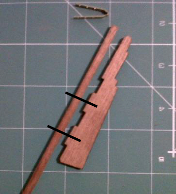
Allan, Thank you for the correct nomenclature. That is really appreciated. PARTS FAILURE! Moving along with the deck furniture, I proceeded to the Fife Rail assembly. After freeing the part from its respective board (I believe it’s Walnut) I was sanding all the little ripples around the edge when the rail broke right across two of the belaying pin holes. I could see right away this was not going to be a fix. Because of the wood grain, brittleness, and the fact it broke across two of the weakest areas, it was going to be prone to breaking again and again. I abandon the notion of fixing and took some scrap 1mm plywood to make a new Fife Rail. I glued the original back together and used it for a template to trace out the shape for the new parts. I figured that I would make two Fife Rails and then glue them together to give me the thickness of the original part. After shaping the outside, I drilled out the belaying pin holes and used the same drill bit to systematically drill out the center. Once I had the new Fife Rail fabricated it was just a matter of constructing the assembly and painting.


- 152 replies
-
- 2
-

-
- bluenose
- model shipways
- (and 1 more)
-
I'm not sure on that idea. There were barrels stowed forward of the main cabin and I would think that fresh water barrels would have been stowed below deck to keep them out of the salt spray. This thing is even too far aft to have a use for fishing because the dories are stowed far forward of this position.
-
I've been building the Schooner Bluenose (Model Shipways at 1:100 scale) and am now up to the point of constructing the deck furniture. In an effort to try and add a little more authenticity to the build I searched the internet for photos and further documentation on the ship. I found a series of old photos that are supposed to be of the original ship. Looking over these photos I found an object on the aft deck next to the steering box. There is no description, that I can find, of this object. It's not listed in the model plans or instructions. I've also posted this with my build log to see if anyone reading it may have a clue. It looks like a round hassock. Any ideas on what it is?

-
As I've been going along I've been doing a bit of research on the Bluenose in an effort to find some further details on the deck furniture. There is only so much I can do at this scale, but I really wanted to make her look a little more authentic. I located some photos of the original ship, or at least they were listed that way, and have found something interesting, ney odd. There is a structure on the aft deck, next to the steering box that is unidentified. In fact this structure is not depicted in this model. Any ideas what this is?

- 152 replies
-
- 1
-
-
- bluenose
- model shipways
- (and 1 more)
-
Went over the plans and instructions again and began construction of the deck furniture. Seems to be pretty straight forward and should move along at a fair pace. The instructions call for construction of three hatches, but the smaller of the three has no ring bolts for lifting the hatch cover. I’m wondering if this is a “hatch” or something else. Its position on the deck is just aft of the Forecastle Companionway. The Main and Aft Hatches were easy enough and after drilling the holes for the ring bolts they really fell together quickly.


- 152 replies
-
- 1
-
-
- bluenose
- model shipways
- (and 1 more)
-
Tim, Thank you for the kind compliment. I'm finding that for the large area, full ship photo that my Canon 40D works best. For the closer shots I'm using a Sony Cybershot. Between these two cameras I can get some decent photos.
-
John & Tim, I can only say that the paint job is thanks to a very dear friend who is an artist. She and I worked for the county sheriff's office and when I retired this past January she gave me a Paasche VL Airbrush as a retirement gift. Her generous gift made the paint job a sucess.
- 152 replies
-
- 1
-
-
- bluenose
- model shipways
- (and 1 more)
-
The next step was to assemble what the instructions called a Bridge. There are three of them, formed from brass wire and a block is lashed to them then seized. Here’s where the material supplied in the kit falls far short of desirable. The rigging line has a plastic feel to it. When it’s unwound from the card it will not relax and you have bends, or folds, in it that won’t stretch out. Not only that, but the glues I’m using won’t stick to it. It’s extremely hard to work with and impossible to form around the blocks. Luckily I discovered this in time to order something better from Model Expo. The new rigging line is much more flexible, forms nicely, and absorbs the glue without becoming too stiff. Using this new rigging line I assembled the Bridges and Blocks then drilled the deck and epoxied them in place.
- 152 replies
-
- 3
-
-
- bluenose
- model shipways
- (and 1 more)
-
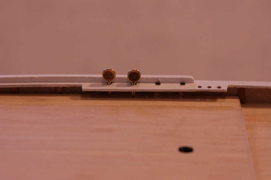
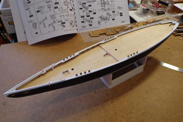
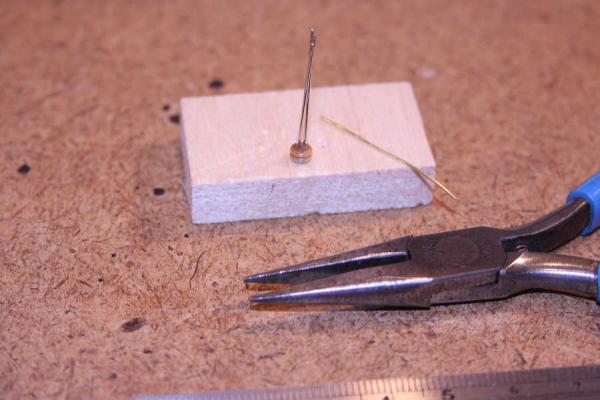
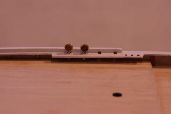
I’ve been able to make a great deal of progress these past couple of days. It seemed as though I was slowed to a snail’s pace with the hull finishing and painting. Sanding, filling, sanding, priming, sanding, masking, painting, sanding, ect. At least now the building has the appearance of progressing. Brass wire is formed around the Deadeyes then the finished the assembly is epoxied into the Gunwale. Please feel free to provide any corrections you may deem fit for the proper nomenclature on these parts. The instructions are very sparse in this area.
- 152 replies
-
- 1
-
-
- bluenose
- model shipways
- (and 1 more)
-
After a bit of delay: trip to San Diego, the July 4th celebrations, and our grandson’s 2nd birthday, I am back at the workbench. I’ve moved building into the house and set up a card table in the library. At least I’m out of the 110 degree temperatures we’ve been experiencing of late. From this point on there shouldn’t be much dust from sawing, drilling, sanding, etc. Now that all the major painting is complete and I am ready to begin construction of the deck furniture. Maybe now it will look like I’m actually making progress as the little bits and pieces go onto the deck.
- 152 replies
-
- 4
-
-
- bluenose
- model shipways
- (and 1 more)
-
Wolf, If the rudder butts up against the transom you can still install two wires at the points where they contact. Even if you have metal straps attached to the rudder and transom, just notch the straps enough to allow the wire to go through them and allow them to touch.
-
Eddie, Make sure you notch the copper (or brass) strips that fit next to the wires. This will allow the strips to conceal the wires.
-
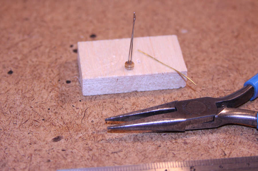
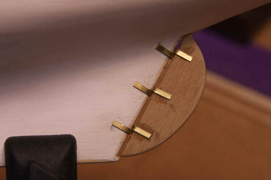
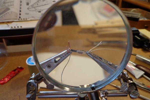
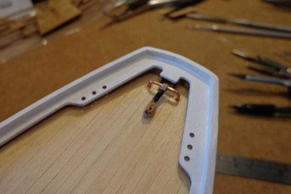
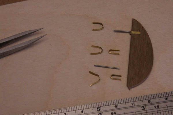
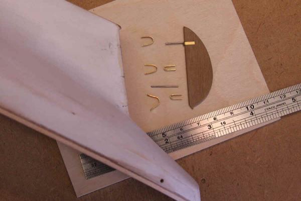
I ran into a similar problem on my 1:100 scale Bluenose. The instructions called for the rudder to be butt glued to the keel and then cutting the brass strips to lay on the outside of the hull and rudder. I didn't like the look of it so I did the following: I cut two pieces of 1/32nd inch piano wire, drilled the rudder, and inserted the wires into the holes. I formed the copper strips (hinges) around the rudder and around the keel. The hinges that would conceal the wires were notched so the wires would fit between the two hinges. The rudder was lined up to the keel and holes drilled in the keel to accept the wires. The hinges were glued to the keel and rudder then the rudder wires were inserted into the keel and glued with epoxy. The overall affect is that the rudder is spaced from the keel by about 1mm. This gives a more realistic look to the assembly.


-
Dave, glad I could help. Over the past couple of days I've been able to re-mask the hull and prepare to spray the upper section black. After I had the masking tape in place I went over the edges with a thin coat of the underlying color. In other words, where the tape covered the red, I painted a coat of red, and where the white (for the gunwales) will be, I painted a coat of white. This should keep the black from bleeding into the other colors. It used to work for model airplanes...don't know why it won't work here. I sprayed the first coat of black, lightly sanded, and then sprayed a second coat. Seems to have come out pretty good. I will not get a chance to complete anything further for about a week. The Admiral just found out that our daughter has been cleared by her doctor to resume normal activity following surgery and we can get out of this heat for a while. We're heading for San Diego on Sunday. That should give the paint a chance to cure properly.

- 152 replies
-
- 1
-
-
- bluenose
- model shipways
- (and 1 more)
-
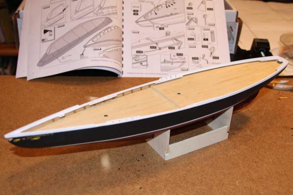
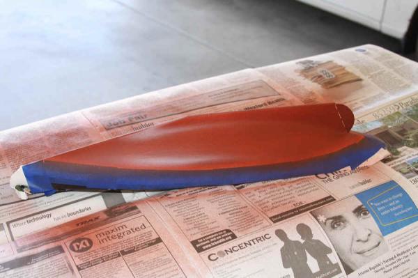
The hull is now ready for painting. This is going to be a somewhat lengthy process because of the weather. I’m not worried about the paint taking a long time to dry; I’m more concerned about the paint drying before it even hits the hull. I’m using an airbrush for the first time and did some test spraying to get feel of the airbrush and adjust the spray pattern. One of the first things I discovered was how fast the paint will dry when the temperature is above 95 degrees. I’m forced to confine my painting to early in the morning. Around here (Surprise, Arizona) the temperature is already at 85 degrees at 6:00 AM. By 10:00 AM we’re already approaching 100 degrees. After tracing the waterline I used 3M Automotive Masking Tape to cover the hull above the waterline. That accomplished, I applied the first coat of red. In the time it took to clean the airbrush the paint was already dry to the touch. A light sanding and I applied the second coat of red. I plan on letting this set for at least 48 hours before I pull off the masking tape and begin prepping for the black paint. It may be next Saturday before I can get back to it.
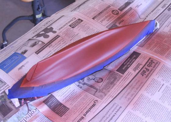
- 152 replies
-
- 1
-
-
- bluenose
- model shipways
- (and 1 more)
-
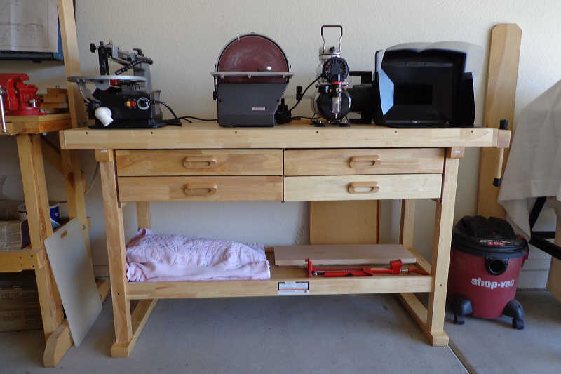
Harbor Freight Workbench
jre8655 replied to Landlubber Mike's topic in Modeling tools and Workshop Equipment
Mike, When you decide to purchase one of these workbenches; Harbor Frieght has two of them listed on their website. One is listed as "60" Workbench" and the other is listed as "Workbench With 4 Drawers, 60" Hardwood." I really can't figure out what the difference is because they both have the same description and specs and are the same price. I went with the second one. Wait till it goes on sale. -
Time to install the rudder. The instructions called for the rudder to be butt glued to the keel then the copper strips glued to the outside of the rudder and keel to simulate the hinges. This just didn’t look right to me so…I cut two pieces of 1/32nd inch piano wire, drilled the rudder, and inserted the wires into the holes. I formed the copper strips (hinges) around the rudder and around the keel. The hinges that would conceal the wires were notched so the wires would fit between the two hinges. The rudder was lined up to the keel and holes drilled in the keel to accept the wires. The hinges were glued to the keel and rudder then the rudder wires were inserted into the keel and glued with epoxy. The overall affect is that the rudder is spaced from the keel by about 1mm. This gives a more realistic look to the assembly.


- 152 replies
-
- 2
-
-
- bluenose
- model shipways
- (and 1 more)
-
Harbor Freight Workbench
jre8655 replied to Landlubber Mike's topic in Modeling tools and Workshop Equipment
Mike, I purchased the Harbor Frieght Workbench about three months ago. I love it! It's as sturdy as any workbench I've either owned or used. Assembly was very easy and I was able to do it unassisted. I waited until it went on sale for $129.95. I contemplated going to our local Harbor Frieght, but opted to have it shipped to my house because shipping was only $6.99. Yeah! $6.99 and it came from California.
-
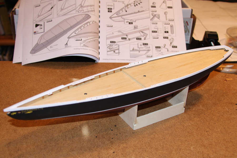
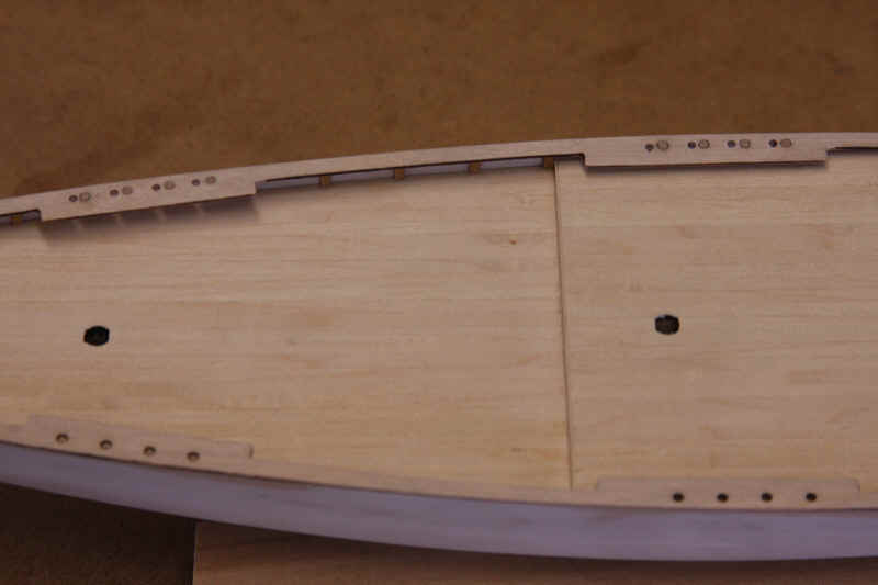
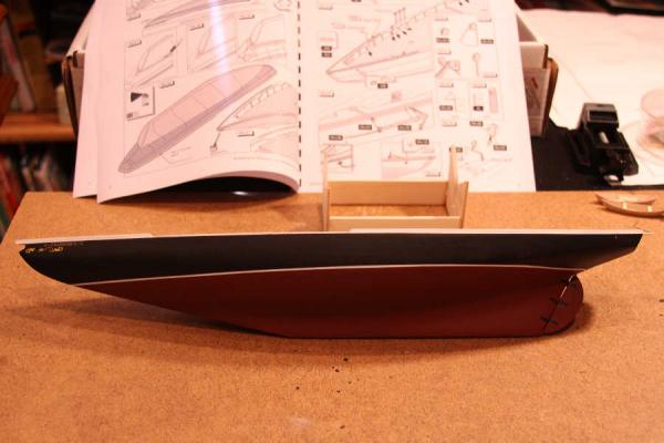
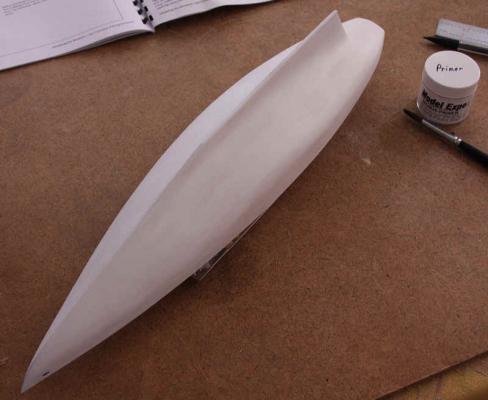
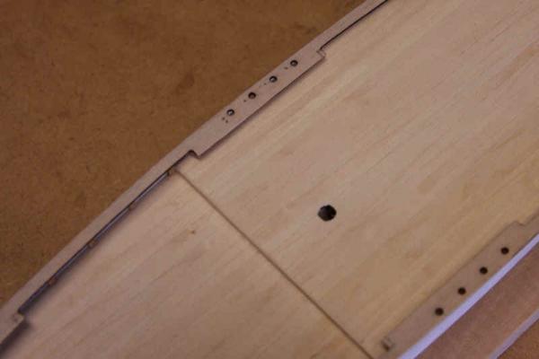
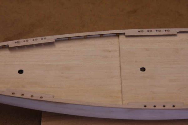
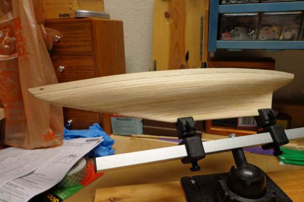
Progress has been slow, but the hull is now primed and sanded. I applied the first coat of primer, sanded this down to the planking. A second coat of primer was applied and finish sanded smooth. The poppets were then glued to the bulwarks and sanded flush with the top of the bulwarks. Those of you that are either building this particular model, or plan to, need to watch out for this next bit. After the cut is made to the stem for the bowsprit; the instructions call for the gunwales to be glued to the top of the bulwarks. I went right ahead (all fat, dumb, and happy) and glued the first one in place. Then I aligned the second one, at the stern, with the first one and glued it in place. The two gunwales did not exactly align at the bow however, and I didn’t think that much of it because I could just do a little cutting and finishing to produce a nice alignment. I was double checking my glue joints when I discovered that the pre-cut holes in the port and starboard gunwales do not line up. The two parts have been cut differently. Measuring these holes I found them to be off by about two millimeters. It was significant enough that had I not corrected the problem all the rigging would be askew when finished. After making the measurements, I plugged the holes on the starboard side and re-drilled them to match the port side. The plugging was easy; I just used the tapered ends of some round toothpicks. These fit very nicely into the holes and sanded smooth. Doubt you’ll even see any trace of them after painting. I tried to show, in the photos, how this misalignment looked before and after correction. The last photo is a combination of a photo before the fix and one taken afterward. Hope this helps. So, what did I learn? Two identical pieces probably aren’t!!
- 152 replies
-
- 1
-
-
- bluenose
- model shipways
- (and 1 more)
-
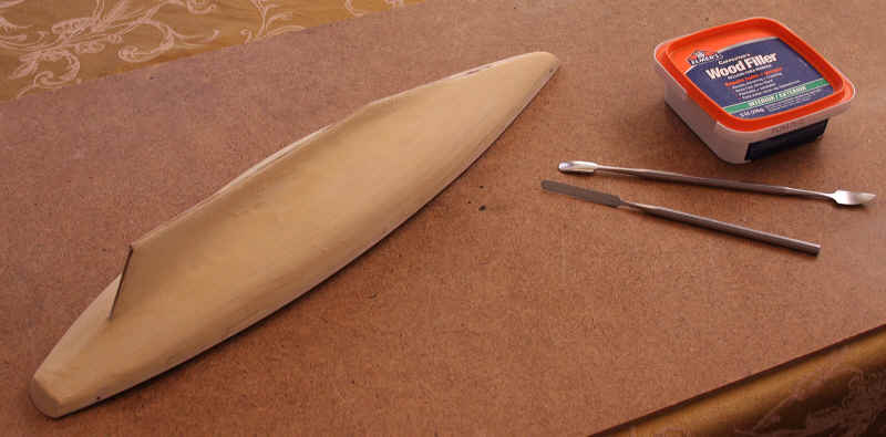
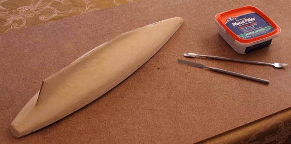
Stayed up late last night and applied a coat of Elmer's Wood Filler to the hull. I thinned the filler down somewhat so I could get a into all the crevices between the planks. Application was done using two different spatulas and then my fingers to achieve the concave curves. I'll give this a chance to cure completely then begin a final sanding.
- 152 replies
-
- 1
-
-
- bluenose
- model shipways
- (and 1 more)
-
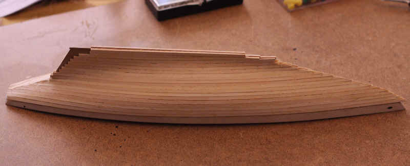
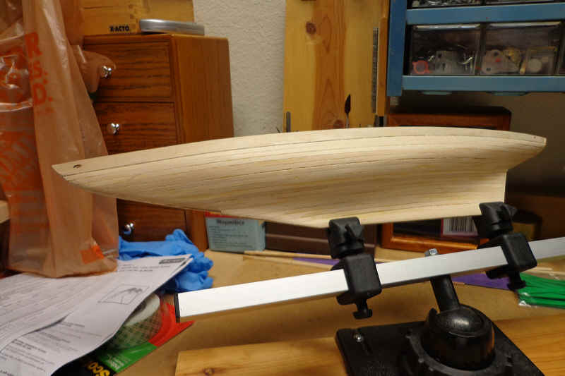
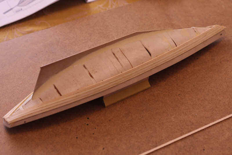
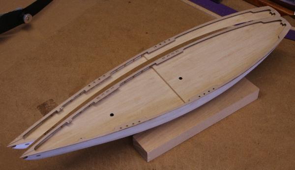
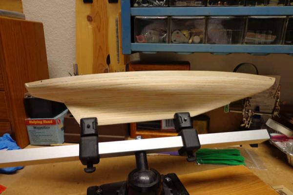
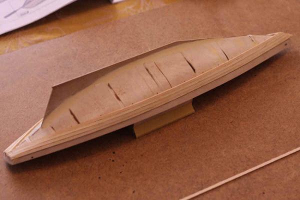
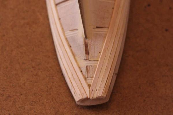
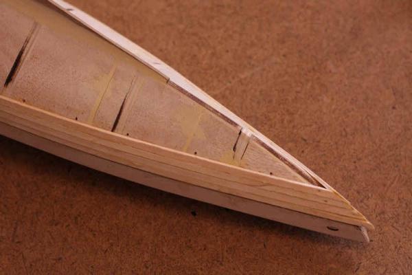
I had a chance to get the planking done over the three day weekend. Adding the filler blocks between the bulkheads really helped. I was able to ensure that the planks were glued along their entire length. Most of the sanding is done. Still a little more to go. I'm not too concerned with the gaps between the planks right now. I'll fill those in with wood filler to get a nice smooth surface.

- 152 replies
-
- 1
-
-
- bluenose
- model shipways
- (and 1 more)
-
Tim, Thus far I think the kit itself contains very good wood. The instructions are easy to follow. The only problem I've encountered is the one with the stern reinforcement blocks being misnumbered on the parts sheet. There is an addendum which adds a strip of basswood onto the bulkheads at deck level to fill in the notch cut in the bulkheads before installing the bulwarks. I'm not sure why the notches were cut into the bulkheads because if you do install the bulwarks without this filler strip the planking will not butt up to the bulwarks properly. So someone at Model Shipways caught this error and corrected it in the instructions. I have installed the basswood filler and the bulwarks and begun the hull planking. This is going slow because of some family medical issues, but is progressing. I figure if I can at least get one or two planks installed in the evenings I'll still be getting it done.
- 152 replies
-
- 1
-
-
- bluenose
- model shipways
- (and 1 more)
-
Ronald, The device I'm using to hold the hull is a Ship Modeler's Vice sold by MicroMark: http://www.micromark.com/ship-modelers-vise,7120.html I actually waited until it went on sale before I bought one. You really don't need something like this to clamp the keel. You can use a couple of strips of square stock screwed to a board. I've seen several on other build logs. The primary reason I purchased this particular vice was because I liked the swivel on the base. You can turn the model just about any direction.
- 152 replies
-
- 1
-
-
- bluenose
- model shipways
- (and 1 more)
-
Give that man a cigar! Yes, Queen of Scots. Formerly: the Corina and then Bournemouth Queen before being given the Queen of Scots name. The photos were taken by me in the summer of 1982 while she was laid up at Blairmore Pier. I was stationed at the U.S. Navy Site One submarine base in Holy Loch which was literally around the corner.