

tomasg
-
Posts
125 -
Joined
-
Last visited
Content Type
Profiles
Forums
Gallery
Events
Everything posted by tomasg
-
 A quick PP on the last pic:
-
Also did the brass handrail on the quarter deck, glued everything in place...


-
Hello...we made the spare support beams, the bow beams, the belaying pin-rails and glued the stern capstan. Nothing interesting to post about how to make them. time to glue most of the superstructure parts... Tomas


-
Made the capstan, at least this is how it s called in the instructions, took a bit more time due to some imprecision of one part two problems, no way one can drill such a wide hole in a so narrow strip and it wouldn t look good anyway, the second one is that one part was milled too much, that means that the part won t sit symmetrical once installed my way of making the axle thinner i then took a 5 mm part for the masts, drilled a hole in the middle then cut away cca. 1 mm making a "donut", painted it gold.... the pictures are way more revealing than what i can see, even if i stick my nose to the model i ll add a few better pics tomorrow Tomas


-
That s great to hear Sailor1234567890 , we need some younger modellers to lower the average age here Tomas
-
Windlass, the tricky part was widening the holes of the "capstans" for the rods to fit, it s good that brass is not to hard: Next where the pumps: the holes of the cylinders where to narrow for the pistons it also has a name now, the portholes, the crew heads where i made a "roof" as with the wheel house and the quarterdeck "balustrade" handrail. Tomas


-
Hello, some progress: we done the "bollards", i hope the translation in google is correct, again no mention at all in the instructions of them. Some of the smallest parts i ever did, as with all pre drilled holes these where to small so i had to widen them all, very tricky since the holes where on the very borders of the bases. Since the "knobs" looked better on the larger bases for a moment i has a doubt that they might fit in there , but the plans drawings can t be off that much , also on the pic on the box they are really small... and small they are, it lmost looks like my cent is getting bigger with time... Next the rudder, not mentioned in the instruction again, rhat would not be a problem if not for the fact that it s shape is very different than on the drawings, in fact it s too long to fit and needs to be shaped to be able to install it, unfortunatly i deleted the pics of the comparison of the original shape my tool to drill a large hole into a thin surface the hinges where on the largish side of things next where the windlass, i ll post it in a few minutes...


-
Hi, to me it looks like it just needs to be tilted to fit, i mean, the slot and the part that goes into it are of the same width and it looks like they can fut into each other. If you can t tilt it then i think the problem might be the order in which you put togheter the parts. Just my humble opinion, from what can be seen in the pics, anyway shaving it off to fit won t cause major problems.. Tomas
-
Yes Nenad, one of the good things about being such a small scale for this kit is that work goes fast, we finished the planking of the decks in one afternoon. It took a bit longer for the hull to plank though, the planking of the hull took longer, the strips are just 3 mm wide so i put about 20 per side per layer, about 80 in total. Yesterday we did the rudder, i prepared it they planked it, so i am going to install it today. Oh. i just noticed, it 20th of December, we bought the kit exactly one month ago.
-
Thank you, yes one of the reasons we went into this build was to do something different then staring at the TV or sitting in front of a PC, on this cold and rainy winter afternoons.Plus the older one just got his first smart phone in November for his 10th birthday, so we needed an extra distraction. The original idea was to build the Mantua battle station section, but i couldn t find it and it would have take too long to arrive if i bought it online. Yes i did mask it, no way i could so such a straight line Tomas
-
Oh, thank you as always for your interest and explanation, great pictures, i never saw the gearing that s inside! Really a complex mechanism.I did angle my false rod, but upon seeing your pictures i ll move it forward a bit too.
-
Time for the wheel house... I did some research before building it, it s nice that there are many pictures of the Cutty Sark , if you look really hard you can see in the drawings that the house is a bit tilted, the parts needed: This time i did some small modifications to the plans. Also i must admit that this site is a bit addictive, i was never a big fan of super detailed building, my first love still is working with wood, i still see these as models not exact copies of the original, i know most here will disagree on this point of view. Anyway, i decided to do something more detailed this time, probably i won t do it much more on this model, mainly because of the other two builders, i am trying to keep their interest in the build by doing new stuff as quick as possible. The first modification was to cover the house with some planking, the 0,5 x 3 mm was a bit too wide so... i made some 0,5 x 1 mm planks, it was interesting to work with them I also shaved off the sides a bit, giving the top a look of a roof. The wheel turned out to be a bit largish, i made the hole for the axle of the wheel as high as possible, but if i would have put only the two front legs the tilt of the house would have been too large, so i installed two additional ones at the rear to rise that part a bit. When this was done and i dry fitted it, the hole on the deck was only covered in part it looked strange with no connection to the wheel house, so i installed a fake rod that goes in the hole. I hope my wording makes some sense anyway the pic... and the result: The fake rod is a bit too dominant, the "legs" are barely seen, as it is still dry mounted i ll put a thinner fake rod later. That s it...any comments suggestions and critique are always welcomed Tomas


-
Thanx for the interest and the explanation about the windlass, to tell you the truth i don t worry much about those parts, if and when i ll need them we ll see. I must admit i use the instructions in a minimal part, rarely relaying on them, going more by instinct and experience. For me the lacking instructions are not a problem, but since maybe this log will be used by a future builder i pointed it out. And, no there is no mention of those parts anywhere or drawings, even the whole sheet of wood on which all those parts are "engraved" is completly missing in the instructions. I ll post the pics of the instructions for future builders later. Tomas
-
Thank you, so trailboards, there is no mention at all of them in the instructions so i couldn t get the translation anywhere. Yes the brown pieces are the two lateral parts of what is called "windlass" in the instructions. It s the larger rectangular ones with two holes in them i am wondering about.
-
Thank you Steve, yes it s a little mystery but sooner or later i ll find out what they are for in my humble opinion even the die cast metal parts that i installed today would look better if they where made from a thinner etched brass, maybe glued first on a wooden support of the exact shape and then glued in place, just like with Le Suprebe. They are just too think and "raw" for such a small scale. Tomas
-
Time for an update....installing the port shutters, as always the instructions are way too detailed about it those used to be made of etched brass so....thats where they where as i side note, i figured out what are those small pieces with two holes in them....still trying to solve the enigma of the larger ones...remember they where made of brass once, any ideas? not very easy to get the position of the port shutters this is the result Time for some ornaments i guess they are of average quality found in kits, i did some adjustments to them, making them similar, the tools i use for such work in the second pic. I got a lot of experience with them building the San Felipe. The one at the stern needed a lot of bending of course, basic rule is to do it slowly and gradually. The figurehead was way to thin to mount it on the keel, i did both widen it and shaved the keel, before gluing it i checked her high with the bowsprit that goes above her The last two pieces, that i don t know how are called, wheren t problematic, apart from the fact that they are very "raw". So the final results: That s it for today... Tomas


-
You can see some basic info on the two links, there s info on the sails of the Le Superbe, which was of a well know Temerarie class, but no info on the sail area of the Thermopylae, which was grater for sure... http://en.wikipedia.org/wiki/Thermopylae_(clipper) http://en.wikipedia.org/wiki/French_ship_Superbe_(1784) http://en.wikipedia.org/wiki/T%C3%A9m%C3%A9raire_class_ship_of_the_line Tomas
-
I am new to this forum, but let me say, great decision to repair her right away, who know how long would it take it to repair her otherwise. Tomas
-
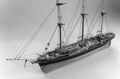
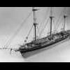
I am surprised, the Thermopylae was longer 65 m to 55 m of the Le Superbe.
-
Thank you for the kind words, the Thermopylae is 1: 124, the Le Superbe is 1: 75, i have to check the dimensions in real life, but i think they where similar...
-
For size comparison, let see if i manage to do the text and pictures togheter... another one... ah...yes!


-
Thank you Nenad for the kind words and the tip!
-
The crew quartres and other stuff is just dry mounted.... Sorry for my basic english, i ll try to look at the instructions in english the plans in the future before posting, to use the correct naming of things. This is it for now, any questions, suggestions and critique is always welcomed...


-
As the senior builder does the tricky work, the younger builders do other stuff:


