MORE HANDBOOKS ARE ON THEIR WAY! We will let you know when they get here.
×


mar3kl
-
Posts
178 -
Joined
-
Last visited
Content Type
Profiles
Forums
Gallery
Events
Everything posted by mar3kl
-
Thanks for the compliment Frank! This part has been fairly straightforward. We'll see how it continues to go. The mizzen shrouds were a relief at this point - only four pairs. The only potentially troubling aspect is that they attach to the channels slightly forward of the mast rather than behind, so when the stay introduces additional tension on the mast, the shrouds may slacken slightly. I tried some different shroud tensions (had to make sure the strops didn't pull out of the chain plates!) and I think what I came up with will be OK. Here's a shroud in the early stages of attachment, with just the collar seized. And the finished result. Again I'm leaving the shroud and lanyard ends untrimmed just in case there's some stretching and I need to redo a shroud or two. And that's it for the lower set of masts. Next up are the stays.

- 249 replies
-
- 2
-

-
- billing boats
- vasa
- (and 1 more)
-
Here are the mainmast shrouds. Very similar to the foremast shrouds; the only difference is an additional single shroud on each side. Technically this should be a single length of rope with an eye splice in the middle to go over the mast. I tried splicing, since the scale rope is laid properly and in theory it's possible. In practice I couldn't do a good enough job, so I just seized a collar of sorts and that looked reasonable. The shrouds at the top... And a close-up at the bottom. The deadeyes are stained mahogany so they don't contrast too much with the hull planking. The lanyards are thin rope, not thread. The seizings are ordinary thread, waxed as needed to get rid of stray fibers. The scale rope needs almost no waxing; I'm not sure why, but it's quite nice on its own. I've left the shroud and the lanyard ends untrimmed. That's because there were several cases where I misjudged the shroud length slightly and without some extra on the ends I would have had to undo the whole shroud rather than just the end. Getting the ends lined up is surprisingly tricky; everything stretches a bit as additional shrouds are set up.

- 249 replies
-
- 6
-
-
- billing boats
- vasa
- (and 1 more)
-
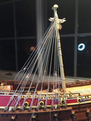
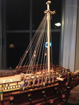
The shrouds were more tedious than anything else. I used scale rope from Syren, because the kit-provided material is not in my opinion of good quality - it looks like string, is too white, and too fluffy. Figuring out diameters was tricky because the plans don't really mention them. I looked in two places. First was "The Rigging of Ships in the Days of the Spritsail Topmast." This is a reprint of a book that is almost 90 years old, and it contains a bunch of useful, although general, information about rigging something like Vasa. Second was a masters thesis entitled "La Belle: Rigging in the Days of the Spritsail Topmast." This paper had a particularly useful reprint of a document from 1667 showing relative rigging sizes. After a bunch of reading I came up with reasonable approximations based on the sizes available from Syren. I had also attached the lower deadeyes to the chain plates using metal strops, rather than the kit-recommended thread. While this looks nice, it was difficult to securely fasten the strops to the chain plates, and I had a few misfires that needed to be re-attached. The following photos show the foremast shrouds at distance, and where they are attached to the top of the mast. You can see that they alternate starboard and port, and are ordered fore to aft. Keeping the tension uniform was tricky, particularly since installing the fore stay will add tension, and possibly start pulling deadeye strops off the chain plates.

- 249 replies
-
- 3
-
-
- billing boats
- vasa
- (and 1 more)
-
And an update from Fred Hocker about the 6-vs-4 hole deadeye debate... The lower deadeye in the pair has four holes, the upper six. Both deadeyes survive for the forestay, but only the six-hole deadeye for the mainstay. The lanyard is rigged with one end tied off to the lower deadeye collar, then led to the upper deadeye, then the lower, and so one. The last turn goes through the sixth hole in the upper deadeye, and the end is made fast back on the collar of the lower deadeye. This was a common setup. Fred Hocker
- 249 replies
-
- 1
-
-
- billing boats
- vasa
- (and 1 more)
-
I believe the upper block is a violin block with one upper and one lower sheave. The lower block is single sheave. I didn't want to deal with making violin blocks, so I went with a double block instead.
-
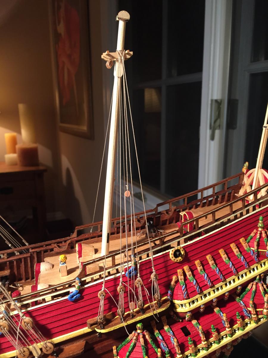
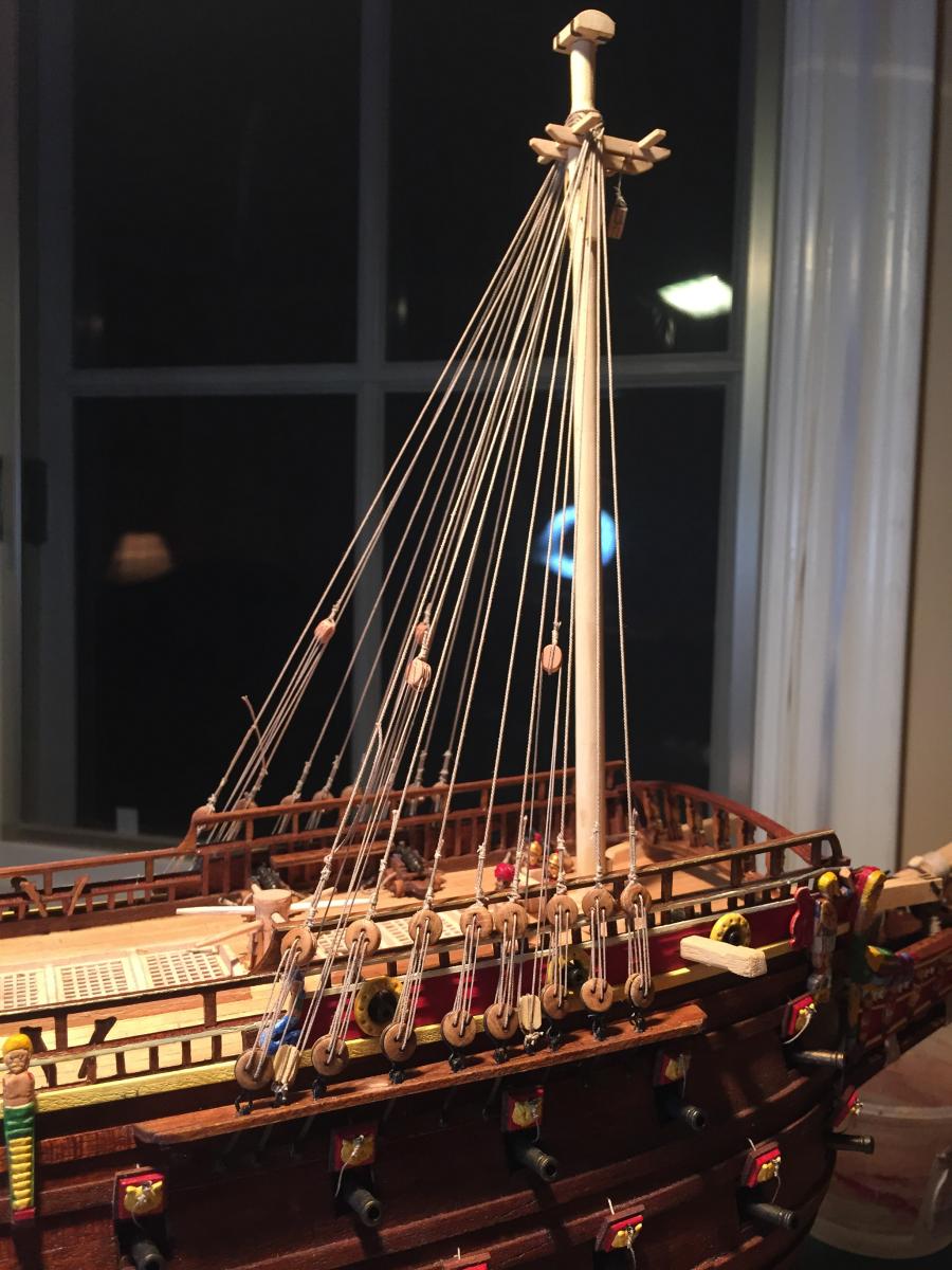
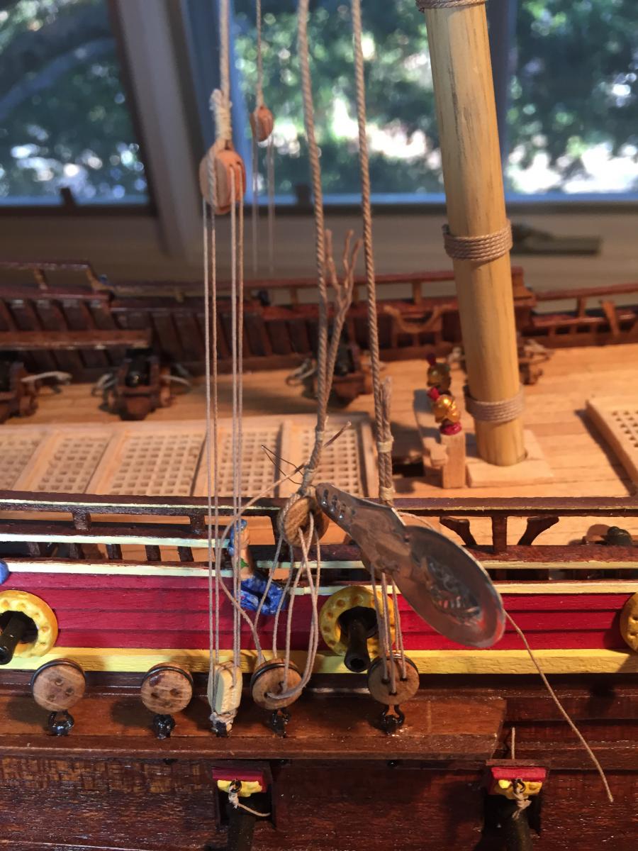
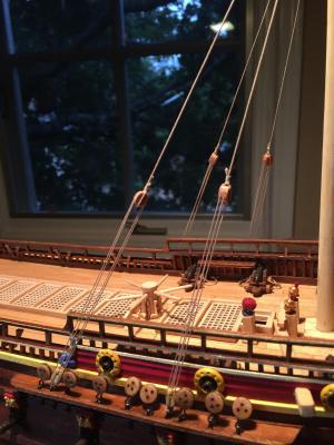
I started the rigging with the mast tackles. The plans appear to be incorrect here. First, they specify no tackles at all for the mizzen, just an extra shroud. Next they specify an extra tackle for the mainmast, three per side instead of two, which conflicts with other sources I've looked at. Finally, the foremast tackles look like they are in the wrong place. So I needed to wing it. Peering carefully at various photos gave me conflicting advice on what the tackle blocks look like and how they are rigged, so I just kept it simple: large double blocks above for the main and foremast, and small double blocks above for the mizzen. Large single blocks below for the main and foremast, and small single blocks below for the mizzen. Here's the foremast setup, two tackles per side: And the mizzen, one tackle per side. I'm hoping the tackles won't cause problems when I add ratlines - it's possible the tackles won't be sufficiently inboard of the shrouds. We shall see. And finally the main tackles. I'm in the process of adding a shroud here - you can see how the deadeye lanyards are routed.

- 249 replies
-
- 3
-
-
- billing boats
- vasa
- (and 1 more)
-
I've decided to fabricate my own 6-hole deadeyes for the lower stay fitting rather than use the kit's 4-hole deadeye. That solves the lanyard routing problem and I'll just hope people don't look too closely :-)
-
It's quite puzzling. I don't know how you'd run the lanyard either, hence the question. And why would you bother having a different number of holes anyway - what purpose would it serve?
- 249 replies
-
- 1
-
-
- billing boats
- vasa
- (and 1 more)
-
I've looked at a few photos of the 1:10 model, the real ship, and Clayton's scratch model. While hard to make out detail, they all seem to show a deadeye setup. Clayton's has six holes in the top deadeye and four in the bottom, like the kit plans, but the lanyard routing isn't clear at all.
-
A question for Vasa builders out there - the fore-stay is attached to the bowsprit using a pair of deadeyes. The plans show one six-hole deadeye from the stay end and one four-hole deadeye attached to the bowsprit. How is the lanyard routed between them given the differing number of holes? Seems not possible to me. The instructions are of course inscrutable - all the deadeyes are labeled "deadeye" and it's only by a bunch of process of elimination that I was even able to figure out that they are paired 6-hole to 4-hole. There is a routing diagram for the lanyard but it's confusingly laid out and I can't understand it. Looks like the mizzen stay and the main stay are done the same way. Any advice?
-
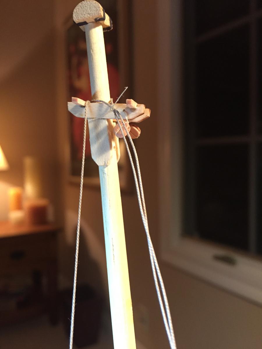
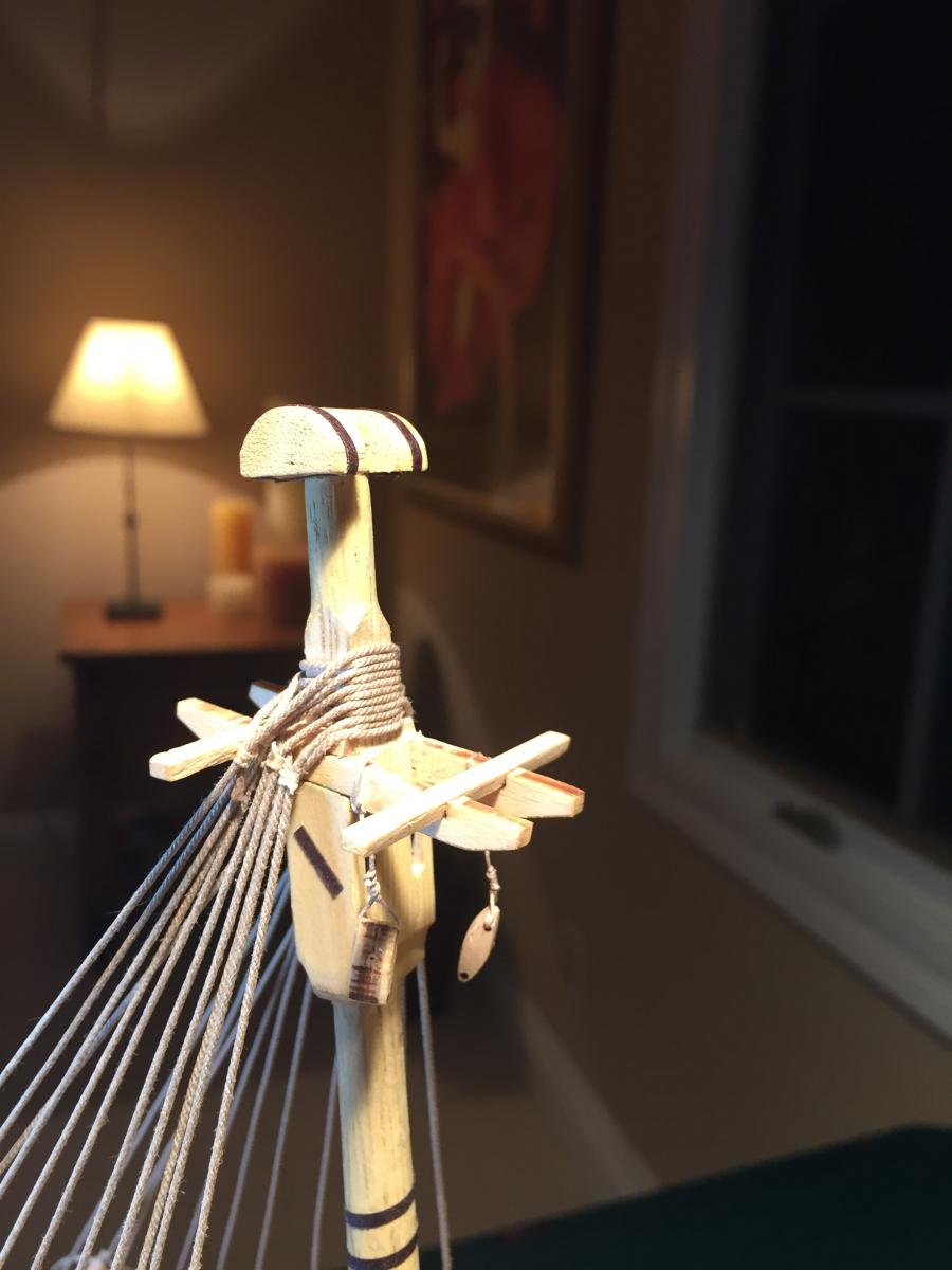
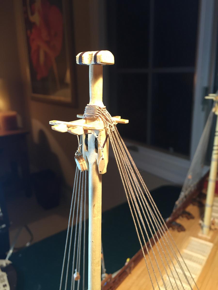
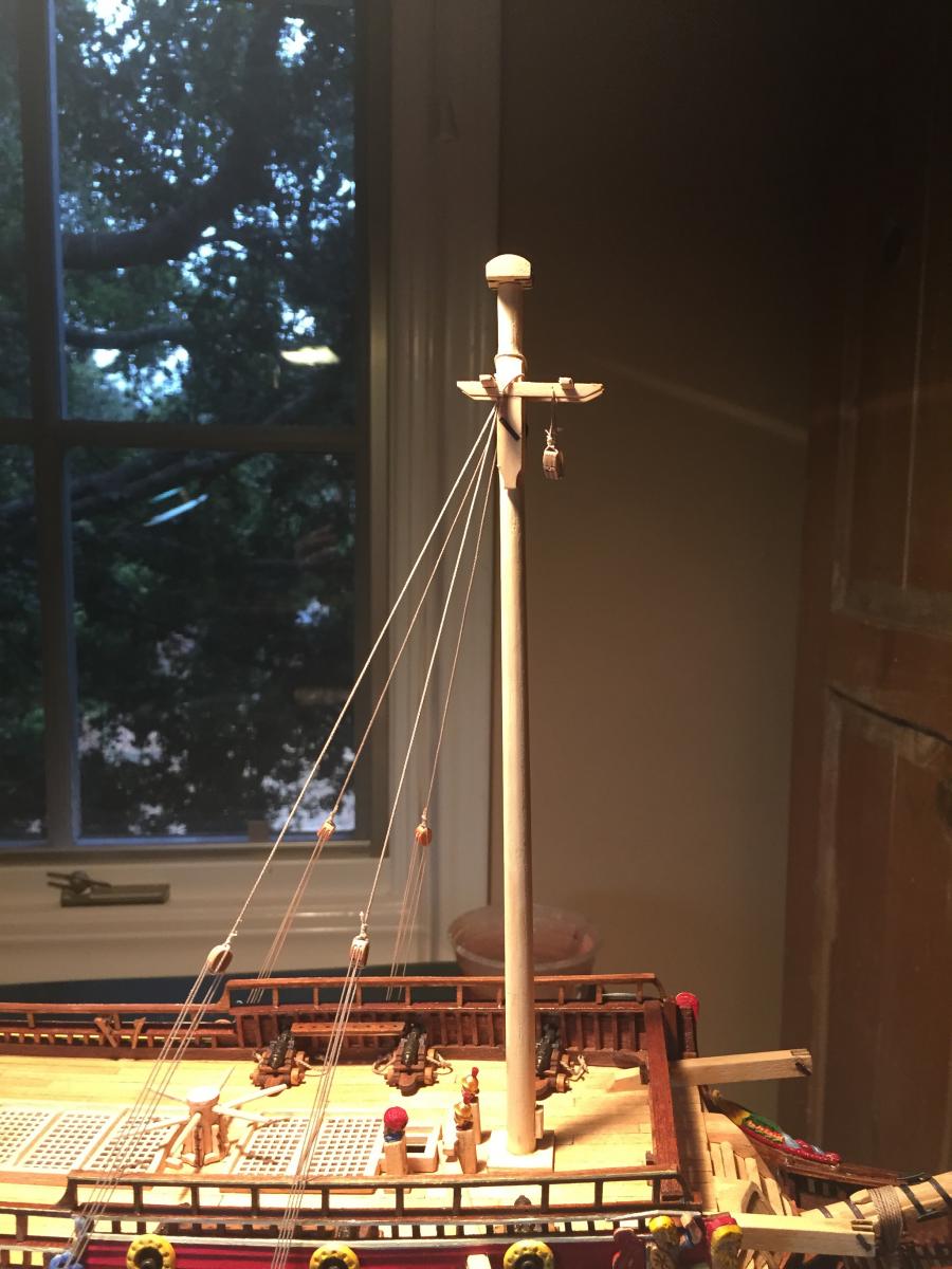
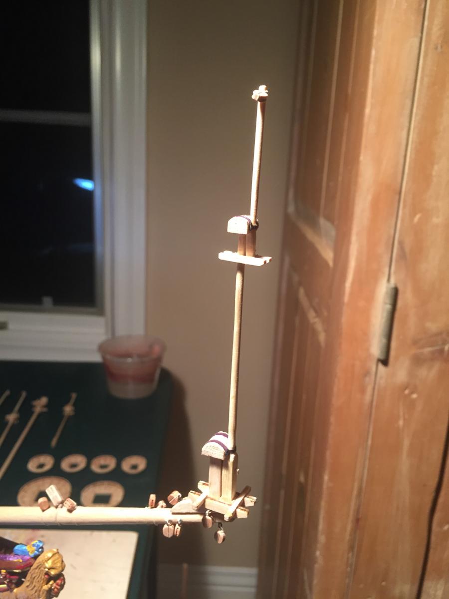
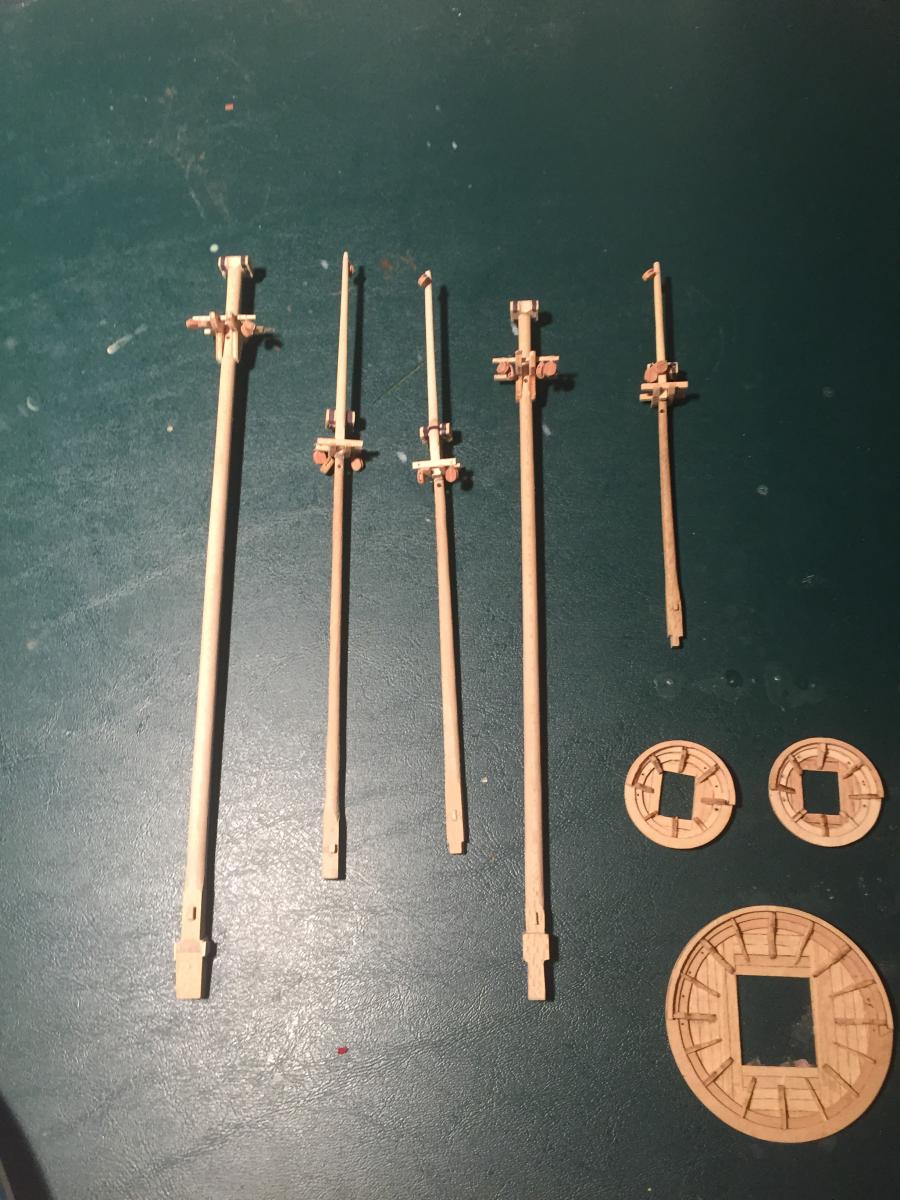
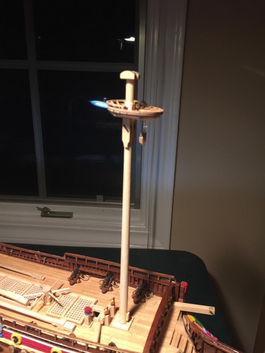
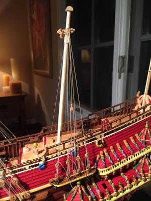
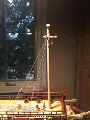
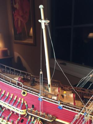
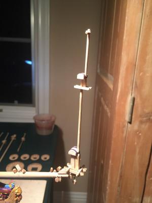
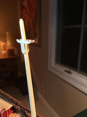
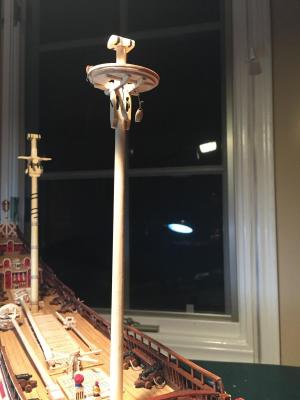
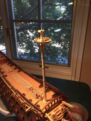
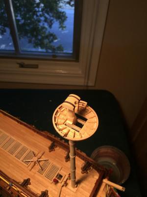
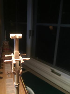
And the mizzenmast. Here's the platform, identical to the fore and main top platforms and the sprit platform. And the mast in place. I've tried to match the rake to the mainmast rake, both slightly less than the jackstaff rake at the stern. I ended up removing the large lantern - it seemed out of scale and distracting. Here's a photo of the sprit top jackstaff in place. The kit didn't provide dowel stock for them that I could find, so I bought some. All the jackstaffs are basically the same - slightly tapered toward the top, with a thin slice of wider dowel at the top for a cap, and a small single block for the flag halyard. And a photo of the topmasts and topgallant masts. All mostly the same, and you can see the shaping of the bases so that they fit correctly in the trestles but don't foul the cheek pulleys. And finally a photo of the completed platforms. They were a lot of work but turned out pretty well. I still need to figure out a good way to make futtock plates and to connect the deadeye strops to the plates. Now it's time for some standing rigging!


- 249 replies
-
- 3
-
-
- billing boats
- vasa
- (and 1 more)
-
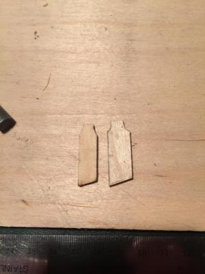
The Billings kit does appear to be more accurate than the Corel, but it has plenty of its own problems. Maybe some day Fred and the Vasamuseet will come up with the perfect kit... A couple of photos of the mainmast. It follows the same design as the foremast - there are two cheeks with slots cut in them and in the mast for the yard lift pulleys. Here I ran into more trouble. First, the cheeks are a different size from what the plans specify, and they don't fit properly under the pre-cut trestles - they are just too small. So I fabricated my own pieces slightly wider. You can see the difference in size below: Next, the kit dowel stock for the masts is oddly from different kinds of wood. The wood used for the mainmast looks completely different from the other masts, both in color and grain. I fixed this by putting a color wash on the mast that toned down the differences somewhat. You can see the result here: Here's a photo of the completed mainmast and the foremast. The mainmast has woldings as well as iron hoops. The plans don't specify the hoops, but I copied the look from photographs, using black paper. You can also see the fore topmast and the main topmast laying on the deck. The main topmast was almost identical in construction to the fore topmast - same size platform, slightly different running rigging blocks. Again I'm following the plans' specification for the rigging blocks and hoping I won't get into trouble later.
- 249 replies
-
- 2
-
-
- billing boats
- vasa
- (and 1 more)
-
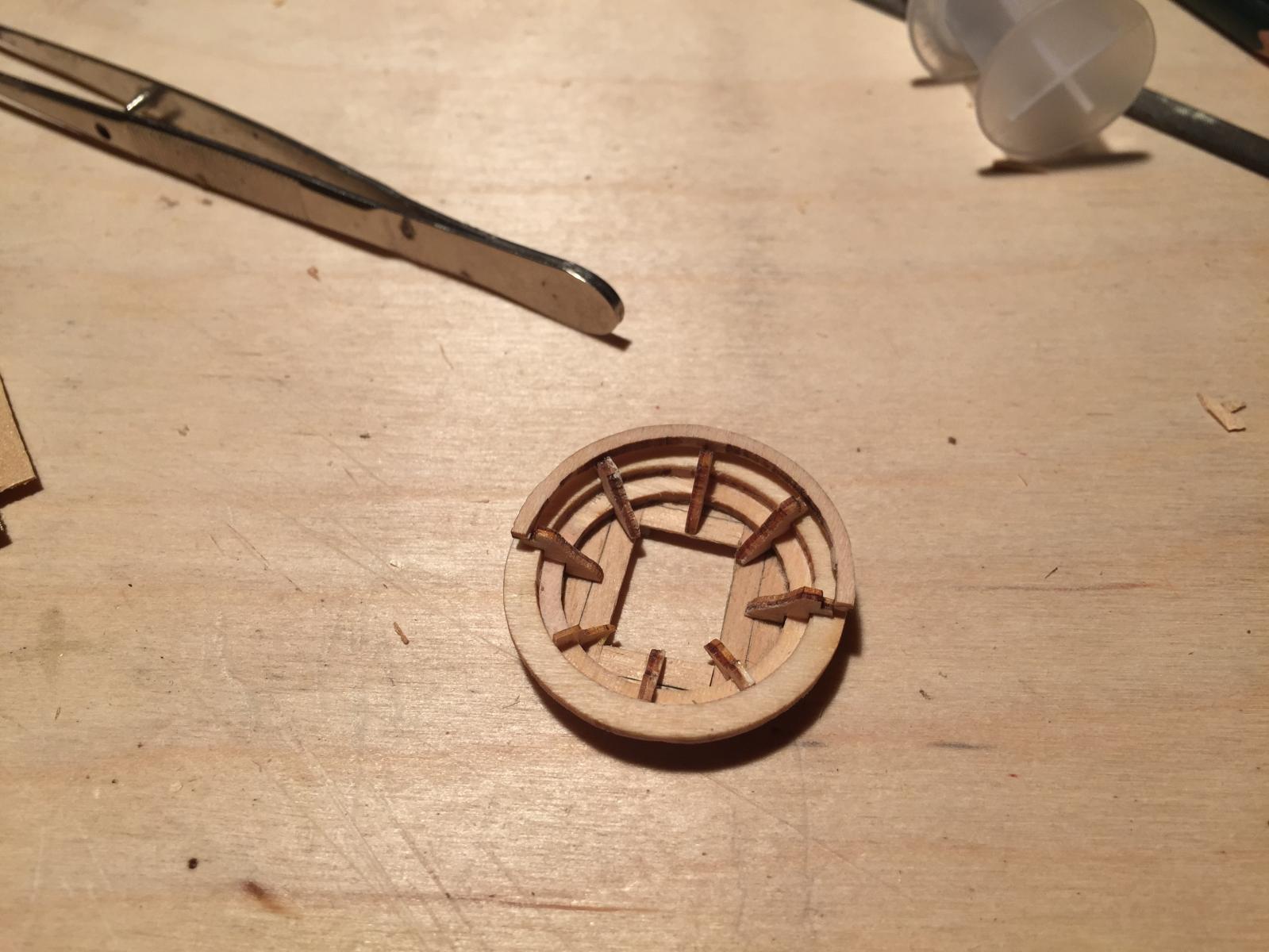
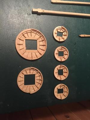
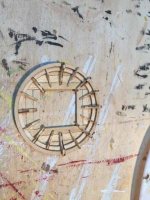
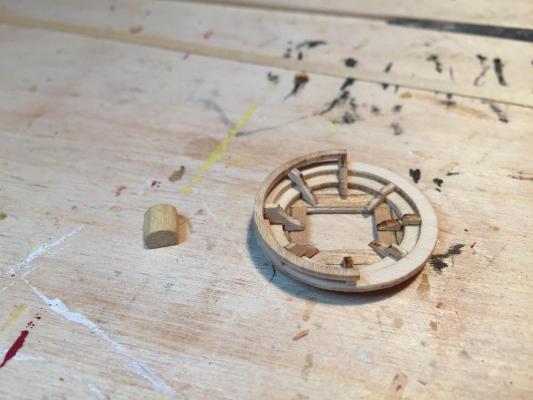
Luckily I didn't need to fabricate the rings. The kit provides them as laser cut plywood pieces. They are too thick, so I did need to delaminate the plywood layers, but that's all. Here are some photos of the main mast platform. Again the opening in the base was wrong and needed reshaping. You can see here how the planking went: Then the excess trimmed... The rings added - again, one fewer than the kit provides, and all thinned down by a third. And finally the completed platform. The braces were again split in half so I had enough to do 16. The real ship's platform has more, but I thought this was enough. You can see the char on the edges from the laser cutting - I couldn't sand it off because the pieces were too delicate, so it'll have to be carefully painted over with a wash.

- 249 replies
-
- 3
-
-
- billing boats
- vasa
- (and 1 more)
-
The platforms are definitely tricky. Thinning down the plywood is difficult and the resulting pieces are very delicate. The result is I think a little more accurate though. Here are a couple of photos of the finished foremast with the platform in place. Again, I removed the woldings later when I discovered the kit plans were wrong and the foremast didn't have them. I also ended up removing the platform, since it will make it easier to attach deadeyes and easier to run the lower shrouds. On to the fore topmast. This was also a little tricky. The dowel stock has a bulge at the base that you file into a square cross section, but it's actually more complicated than that. The bulk of the cross section needs to match the diameter of the foremast above the trestle trees and not cover the pulleys below the trestle trees, which is a bit too narrow for a good fit through the trestle trees. Also, you need to be careful to allow enough of a gap between the topmast base and the foremast for the shrouds to pass through. The plans are again wrong here; they show the topmast base and the foremast joined tightly together. This photo shows what I came up with. And the finished fore topmast with its platform and rigging blocks. The platform is identical to the bowsprit platform - pieces thinned down by a third, base planked, and one circle eliminated. The rigging blocks concern me - they are way easier to install now rather than after the mast and its standing rigging are in place, but the running rigging plans are very difficult to interpret, and I'm hoping I don't need to redo the blocks once I understand the routing better. The blocks by the way are from Syren, not the kit. I didn't like the look of the kit blocks.

- 249 replies
-
- 4
-
-
- billing boats
- vasa
- (and 1 more)
-
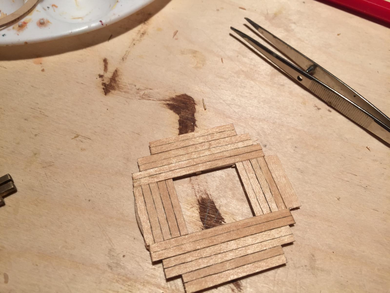
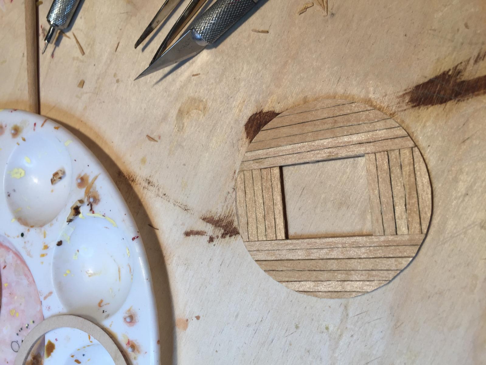
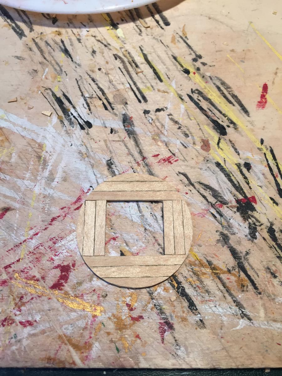
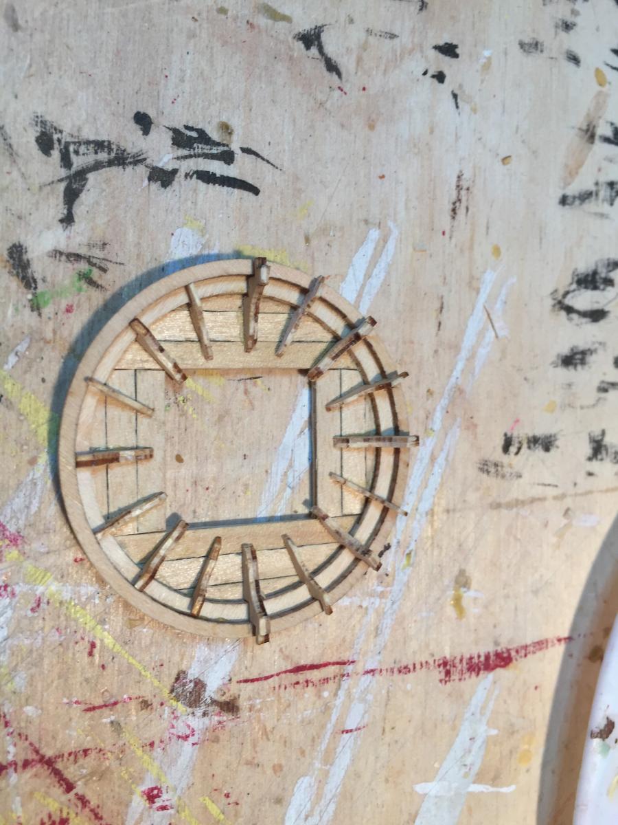
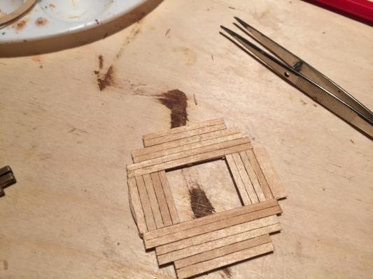
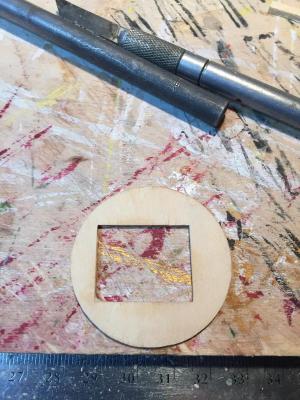
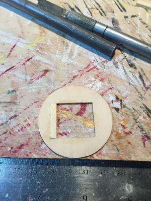
The foremast platform. This required a number of modifications, just like the smaller platforms. First, the center hole was the wrong shape. It's narrow enough that the shrouds will have a hard time passing through, and it's not centered. The photos I've seen of the real ship seem to show a square, centered opening. So I reworked the base to look that way: I then planked the surface in the same pattern as the real ship: And here's the final product. I had to again remove an extra ring and thin down all the pieces by about half to make it look right. The braces again needed recutting slightly to deal with the changed platform profile. I ended up splitting them in half, which doubled the number and let me put 16 around the platform instead of the 8 that the plans call for. This is reasonably close to the real thing. Because all the pieces are plywood and laser cut, there's char on the edges. The pieces are delicate enough that sanding off the char wasn't possible, so I'm going to do some color washes that blend things together.
- 249 replies
-
- 4
-
-
- billing boats
- vasa
- (and 1 more)
-
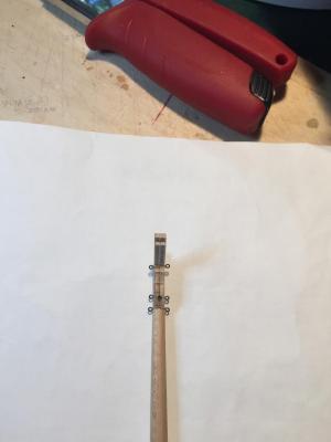
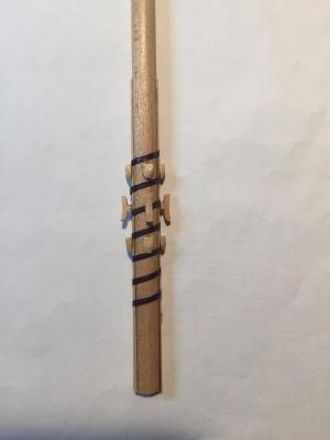
Thanks for all the compliments! On to the foremast. The dowel stock from the kit is wide at the base, tapering toward the top, and then bulging out at the top so you can file the dowel down to make a square mast head. As far as I can tell from various books and internet sources, the mast is also supposed to taper inward about 1/3 of the way down toward the base, so the base is narrower than the mast at its widest point. Since I don't own a lathe, that required putting the dowel stock in a drill and spinning it while pinching the dowel with sandpaper. It worked reasonably well. The instructions and the plans disagreed on the mast length, so I picked one. Here's a photo of the masthead, with the cap, cheeks, and trestles installed. The cheeks are supposed to have metal braces to support the yard lift pulleys; I simulated them with black paper. You can see the topmost of four woldings as well - after I made them, I discovered the kit plans are wrong and the ship didn't have foremast woldings, so I removed them later. The mast cap hasn't had its braces (more black paper strips) installed yet. Another view, where you can see the pulleys installed. They are brass, so I blackened them with brass blackener. Here you can also see two blocks associated with the fore yard running rigging. I installed them early while it was easy. And finally the mast installed. I looked at several sources to try figure out the correct rake. As near as I can tell the mast is supposed to be perpendicular to the deck, with the trestles tipped downward at the fore end very slightly.


- 249 replies
-
- 5
-
-
- billing boats
- vasa
- (and 1 more)
-
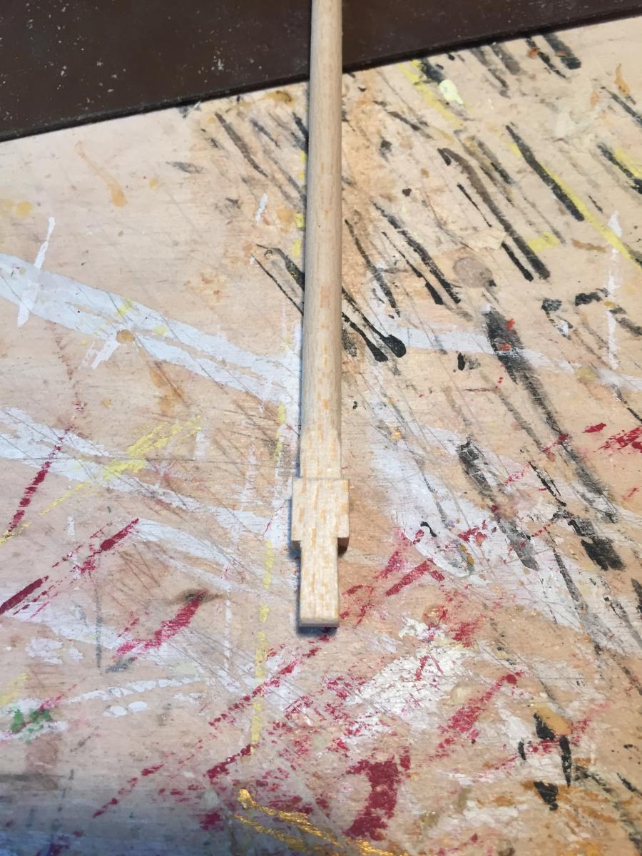
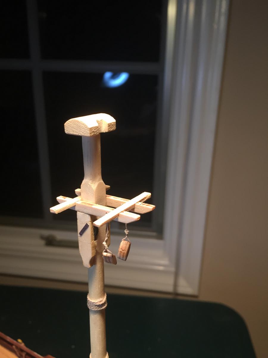
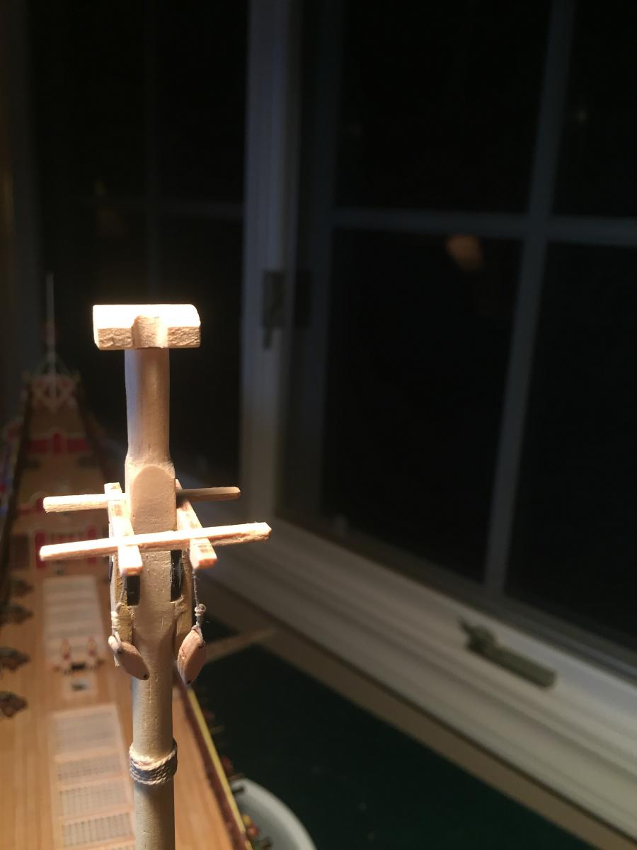
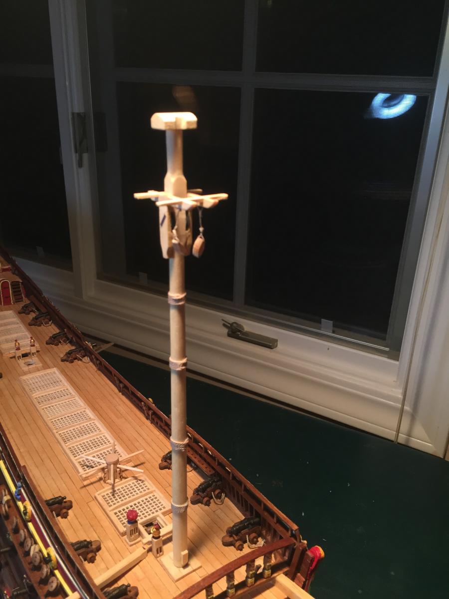
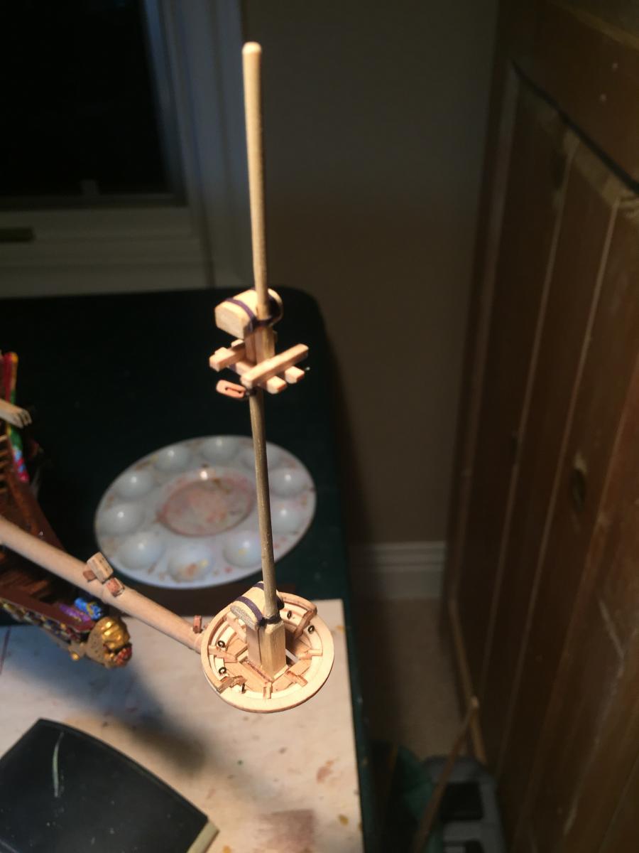
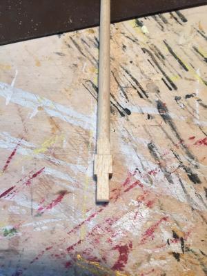
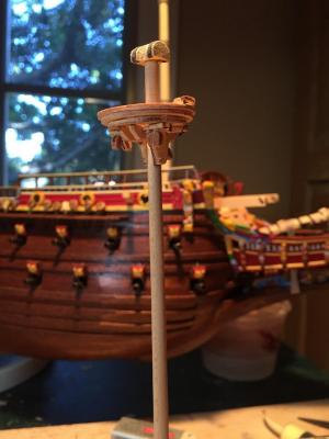
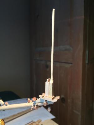
Now the sprit topmast. The kit supplies a dowel with a bulge at the end. You're responsible for turning the bulge into a nice square mast base and simulating a fid at the front. You can also see here the trestles for the platform. Crosstrees added... And the finished mast and flagstaff. I needed to scratch the flagstaff - the kit mentions it but doesn't provide any dowel stock that I could find. There are also vague references to "mast tops" which go atop the flagstaff, but again I couldn't find the corresponding parts. I later ended up scratching them from thin slices of dowel. The lower mast cap needed a slot cut in the bottom to fit over the knee to which the topmast is attached. I added simulated metal bands with paper. The upper mast cap also needed to be scratched - the kit makes reference to a part number but again no part that I could find. I just took some strip stock and made one that looked reasonable. The upper cap needed a hole drilled in the bottom to go over the topmast. Both caps need a semicircular cutout in the front middle, to which the next mast up will be attached and covered with a simulated metal band. I found those cutouts a little tricky - the masts taper and you need to make sure that the cutout fits properly while the mast aligns with the mast or knee below. The kit provides curved metal bands to use here, but I found them overscale and used black paper strips instead. Some more views of the finished bowsprit. It was probably a pretty scary place to crawl out to and work on. One slip and you likely get crunched under the bow.

- 249 replies
-
- 1
-
-
- billing boats
- vasa
- (and 1 more)
-
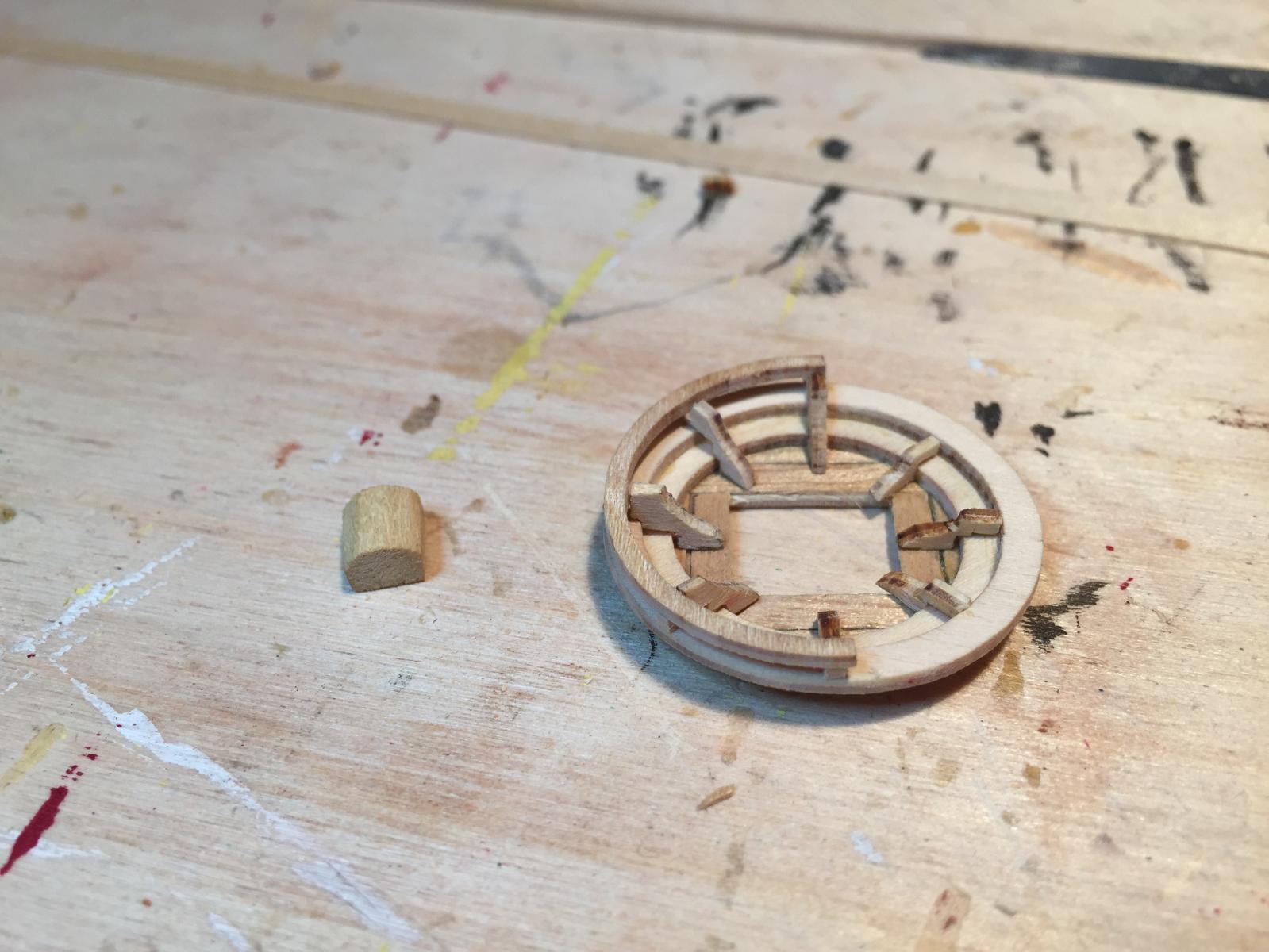
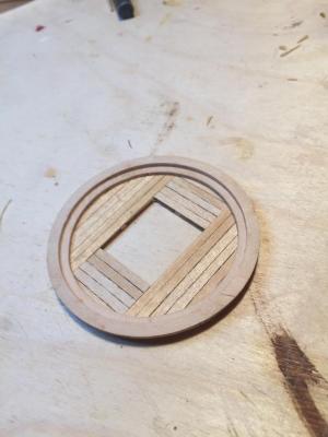
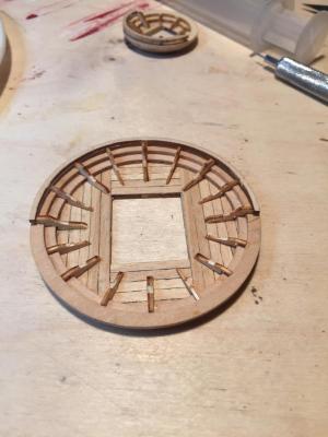
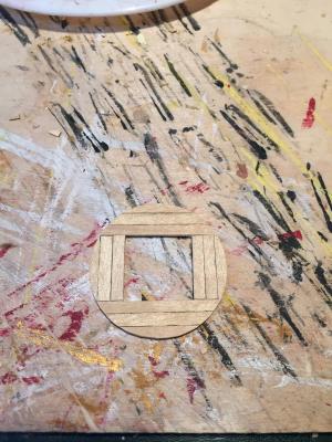
Speaking of the platforms... Here's the bowsprit platform: [ After I pored over the instructions, plans, and part manifests for a while, I figured out that four of the platforms - bowsprit, mizzen, foretop, and maintop - are exactly the same, and layout instructions appear just once, in the area for the mizzen mast. Obvious in retrospect, but not when you are staring at a laser cut sheet of circles and you don't know which go where. In addition, the instructions are wrong about how to assemble the top - part numbers don't match with reality and the diagrams are incorrect. Once I figured out how the top needed to be constructed, I went about modifying it. The pieces are much too thick and there are too many of the rings. I removed one ring and thinned down the base, the two full rings above it, and the half ring above that. Very tricky delaminating the plywood without breaking the pieces, but I managed to do it. Next, I planked the base in a manner similar to the real ship - as close as I could get with my skills anyway. Finally, the kit provides 8 "braces" evenly distributed around the base. 5 are raised to hold the half-circle rail, the other 3 are smaller. I needed to recut all of them because they didn't fit right. Ironically they fit better with the extra ring eliminated. I have no idea how they would fit if you followed the instructions and used all three rings. I thought about adding a full set of them (the real ship seems to have more like 16-20 of them) but they would have been too crowded together. Finally I drilled three holes each side for the futtock plates. I tried several strategies for making futtock plates and attaching deadeyes to them, none particularly successful, so I'm thinking on it for a while. The kit has no information on the subject at all - I assume you use rigging thread, which isn't correct. The result is pretty good. I can't imagine building the platforms completely from scratch identical to the real ship - lots of very delicate pieces. The kit version was OK after all the reworking.
- 249 replies
-
- 2
-
-
- billing boats
- vasa
- (and 1 more)
-
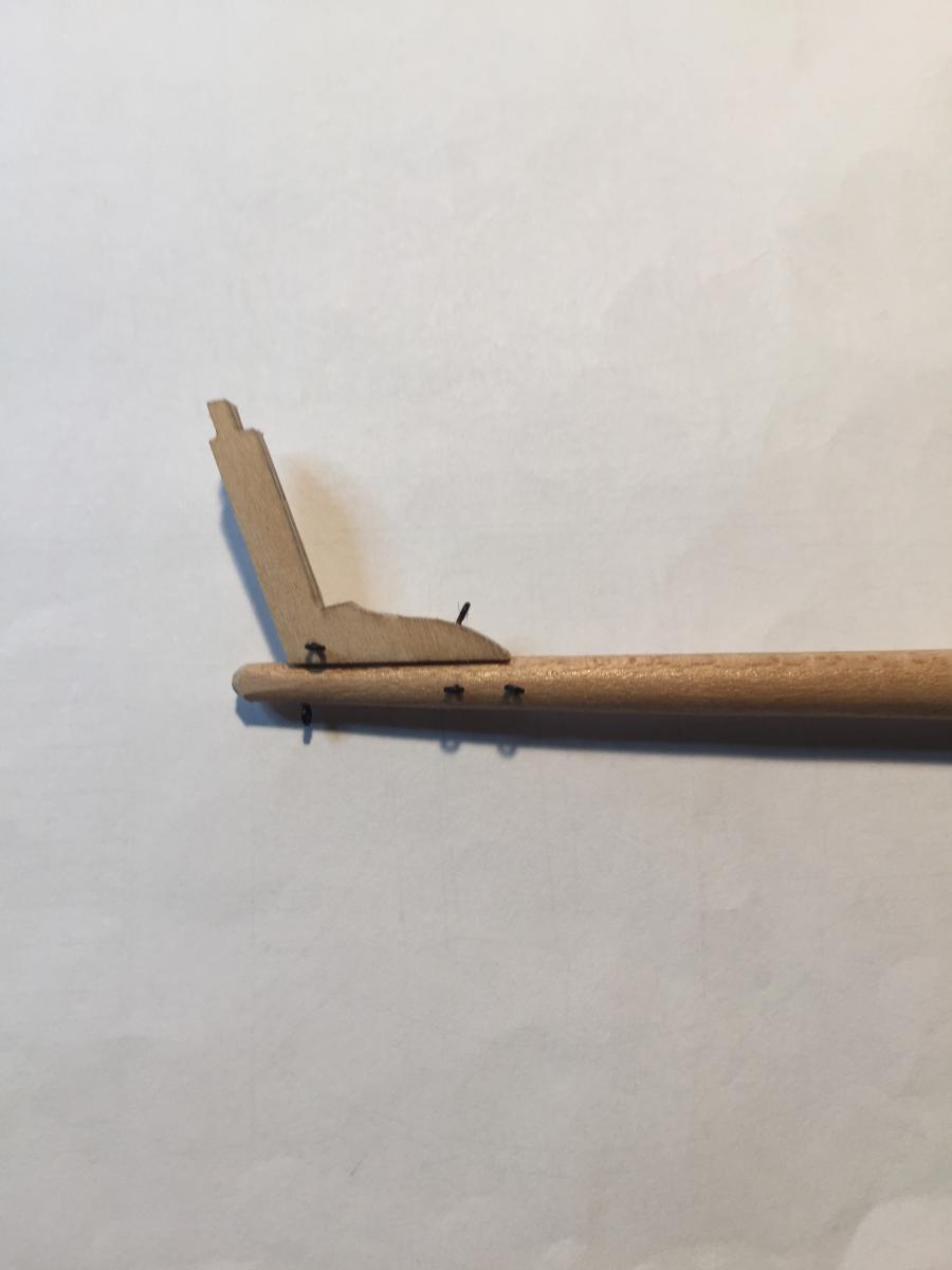
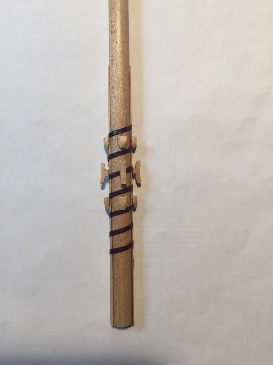
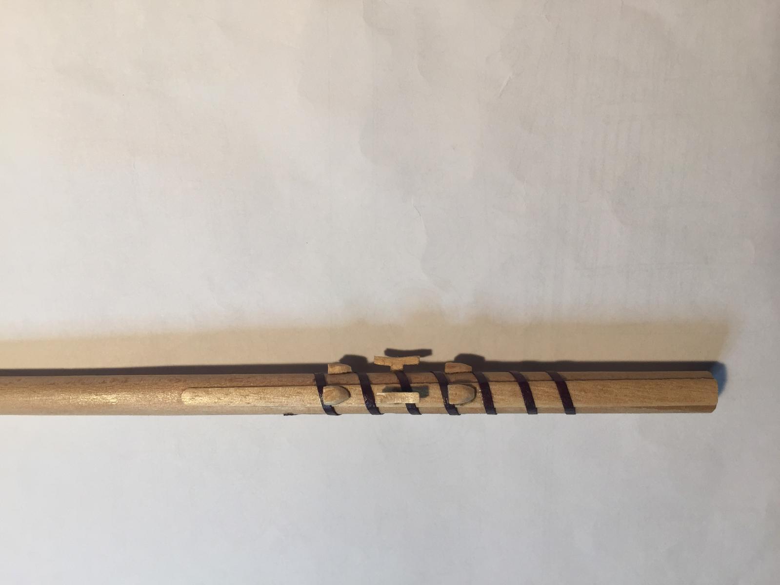
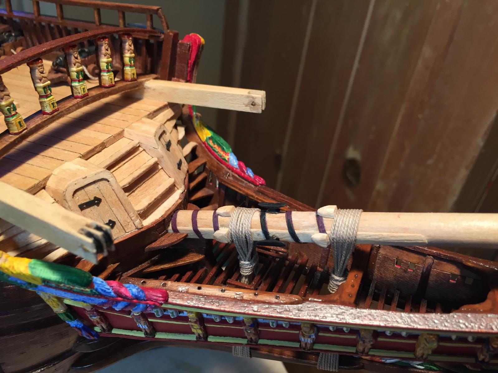
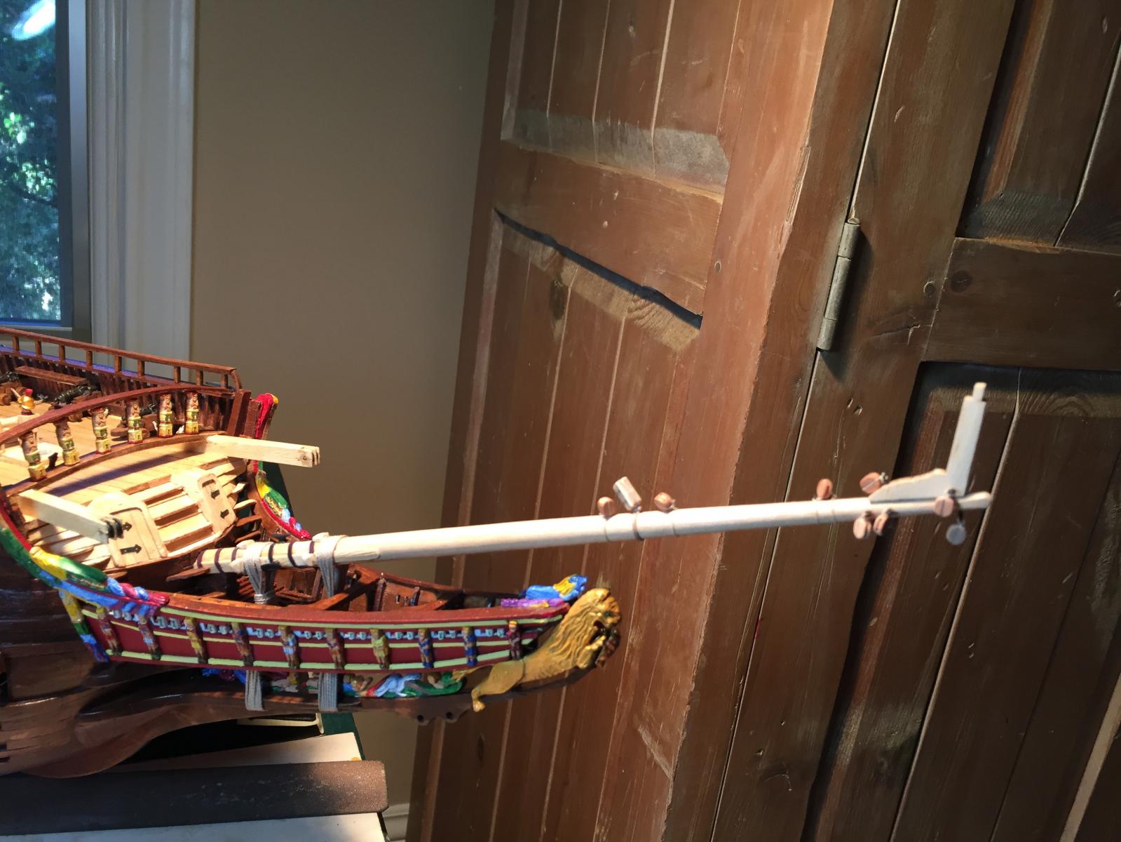
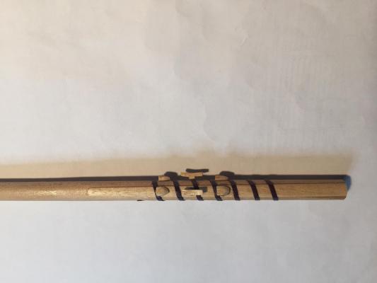
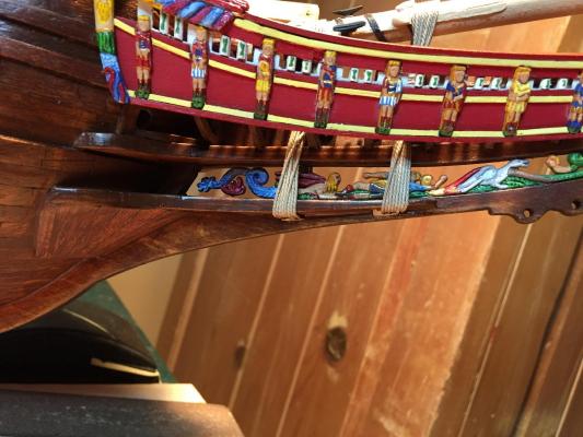
I've spent the past three months building the masts. It's been a complex process, mostly because the instructions are terrible. I've had to engage in a bunch of detective work to figure out which parts go where, because the layout of the laser cut plywood sheets doesn't match the instructions' layout, and the part list isn't descriptive enough (imagine 20 parts for the mast tops, all described as "top" and you get the idea). Add to that a bunch of missing parts, as well as various conflicts between instruction diagrams and full scale plan sheets, and the fun just keeps increasing. With that in mind, I started with the bowsprit and worked backward. There were several false starts and backtrackings along the way, but I'm reasonably happy with the result. Here's the front of the bowsprit, with various fittings attached. And the rear of the bowsprit. I added the spiral binding, made of black paper, as well as reinforcing pieces on each side, made from thin veneer steamed into shape. I couldn't find the kit-supplied cleats so I scratched some up. Oh wait, I found the cleats! Turned out they were made of plastic and buried in with a bag of parrel beads. I liked the shape better, so I removed mine and replaced with the kit's. Note the gammoning: the plans don't mention that you need a pair of gammoning slots at the bottom of the beak. The forward slot requires that you thin down the reinforcing pieces above the slot. A little delicate but doable. The light makes the spiral binding look purple, but it's black. And a view of the bowsprit in place.


- 249 replies
-
- 7
-
-
- billing boats
- vasa
- (and 1 more)
-
Thanks for the encouragement and compliments, and the photos. I'm looking forward to the rigging - it's going to be a challenge looking at various sources and trying to come up with something good.
-
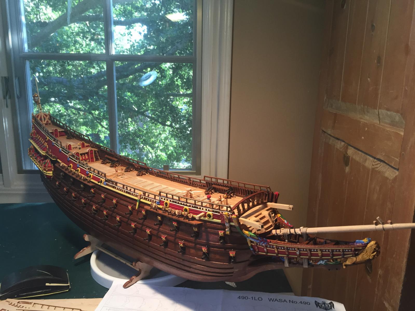
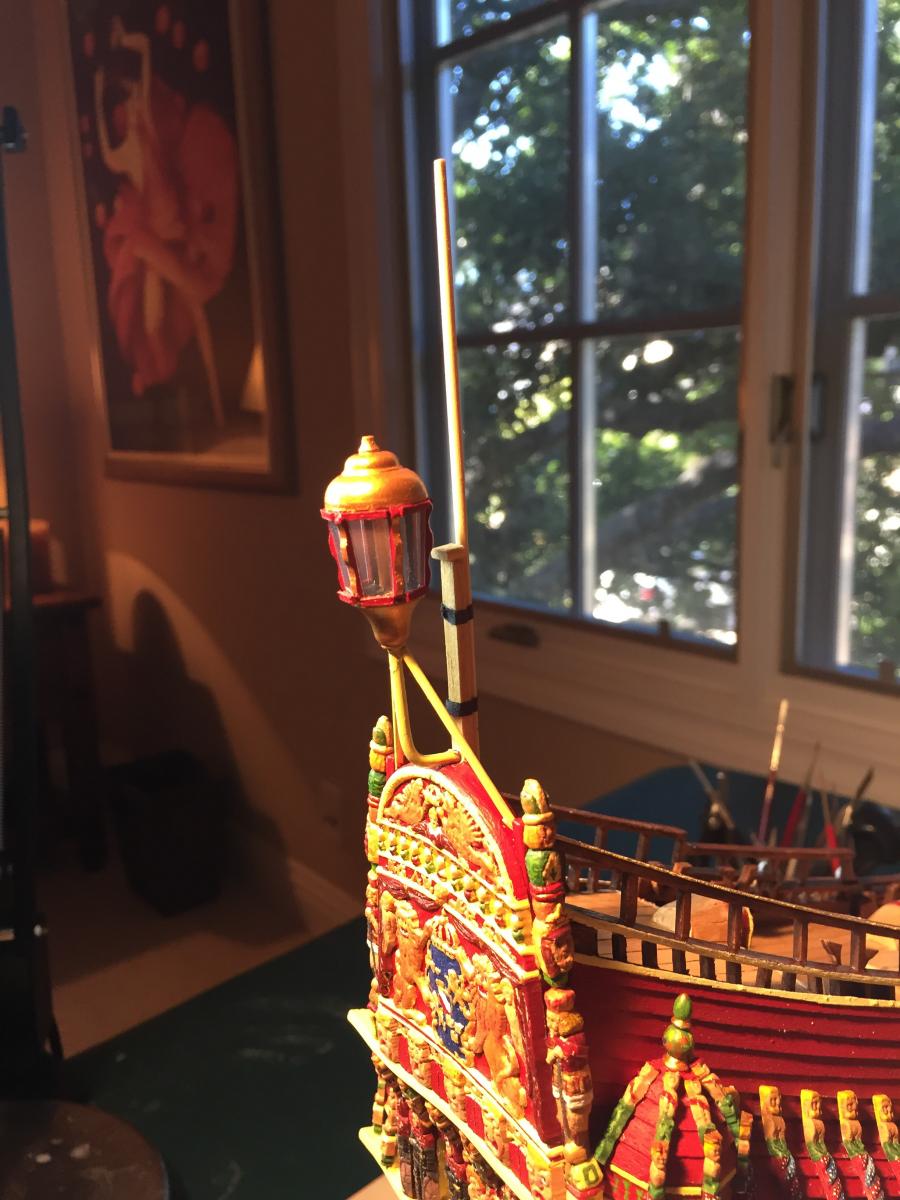
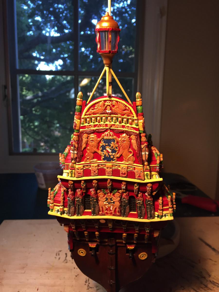
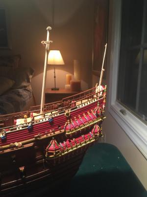
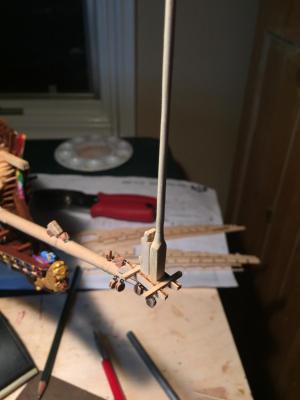
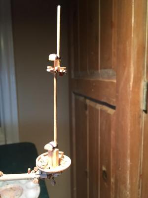
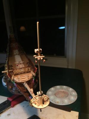
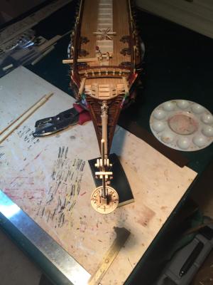
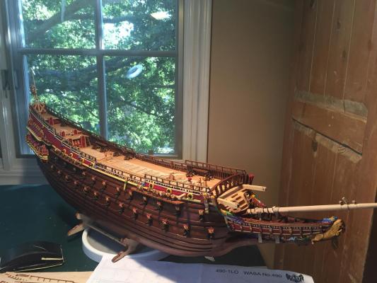
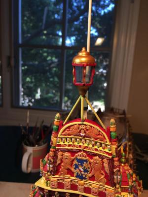
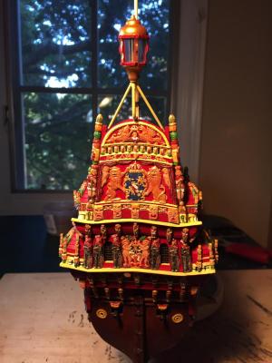
The stern lantern was tricky. The plans have almost no advice (and conflicting photographs!), and neither the original ship nor the 1:10 model have a lantern. So I made something up. Six sides, the frames shaped with a little detail to make them interesting. The top and bottom are turned brass. I primed the pieces and painted them an antique gold. The kit is supposed to provide clear acetate but I couldn't find any so I used some from a clear presentation cover. I really wanted to put plastic screening behind the "windows" to simulate window panes, but I couldn't attach the screening to the acetate without making a blotchy mess. Scribing lines on the acetate didn't work either - the ink kept smearing - so I left them clear. The result isn't too bad; I'm going to live with it for a bit and see if I get any ideas to improve it. Forward of the lantern is the flag pole. This was fairly straightforward. It wasn't clear from the plans what dowel stock to use, and I didn't want to accidentally use some that was intended for masts or yards, so I took a wooden skewer and tapered it until it looked right. I attached it to the spar behind and then simulated some iron straps with black paper. And now the hull's done! Here are some photos of the result. Now I need to go off and think about masts for a while. The plans are pretty sketchy here, and in the absence of Vasa II, I'm going to need to look at as many photos as I can before proceeding.

- 249 replies
-
- 9
-
-
- billing boats
- vasa
- (and 1 more)
-
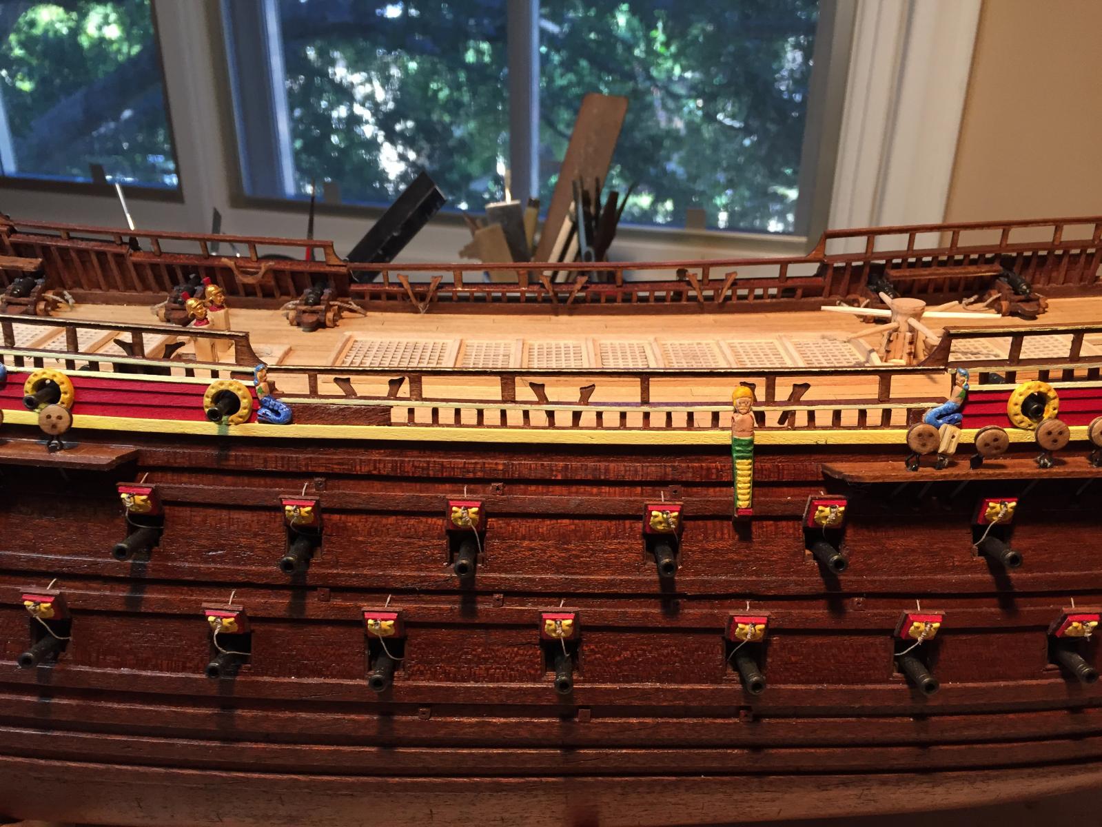
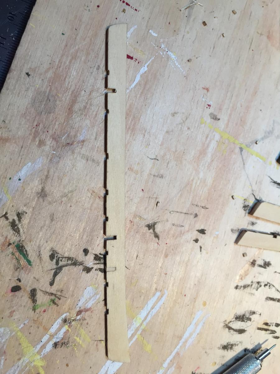
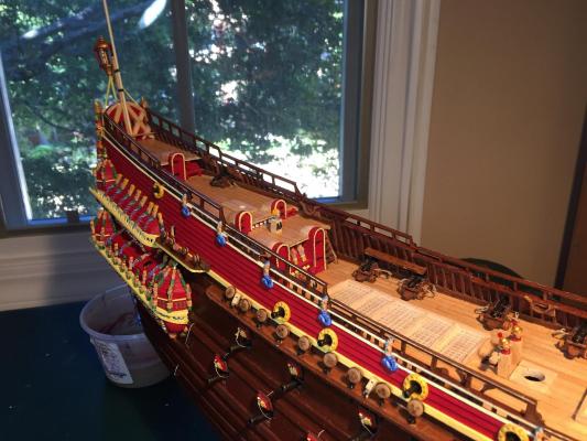
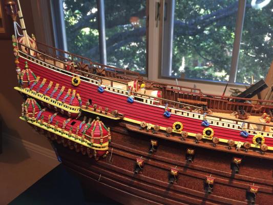
Almost done, as I attach the top rails along each side of the ship. I want to have them in place before I start rigging. First I went back and painted the edges of the railings immediately above the bulwarks. Then I painted the edges of the top railings and installed them. For the most part they fit rather surprisingly well - a few stanchions had to be shortened a bit. The railings are extremely delicate and the plywood is prone to delaminate. All in all a fiddly little task, but it really adds nice detail to the hull. I had to curve the forward rails to match the curve of the hull, which also meant the plank on top of the railing needed to be cut from wide stock and curved to match. Next up are the stern lantern and flagpole, then I'm done with the hull and can move on to the masts.
- 249 replies
-
- 4
-
-
- billing boats
- vasa
- (and 1 more)
-
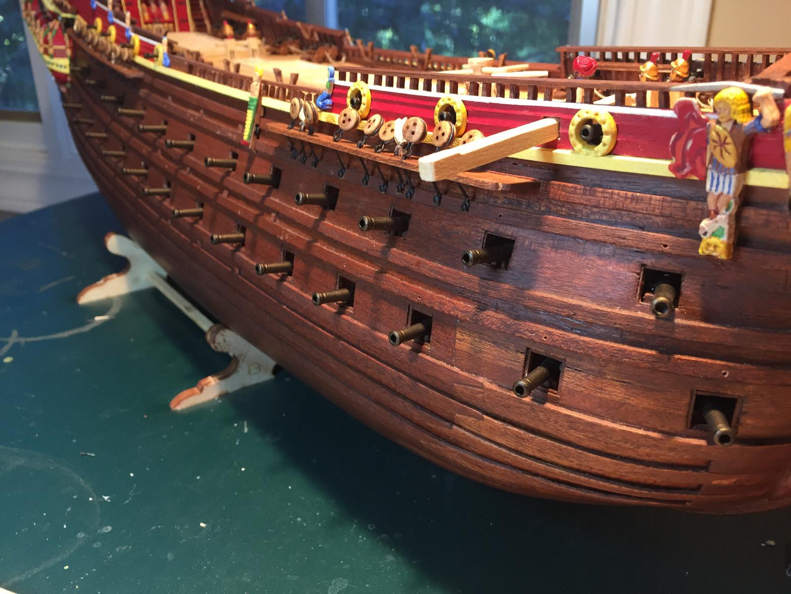
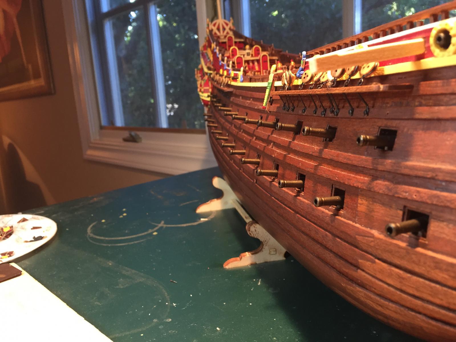
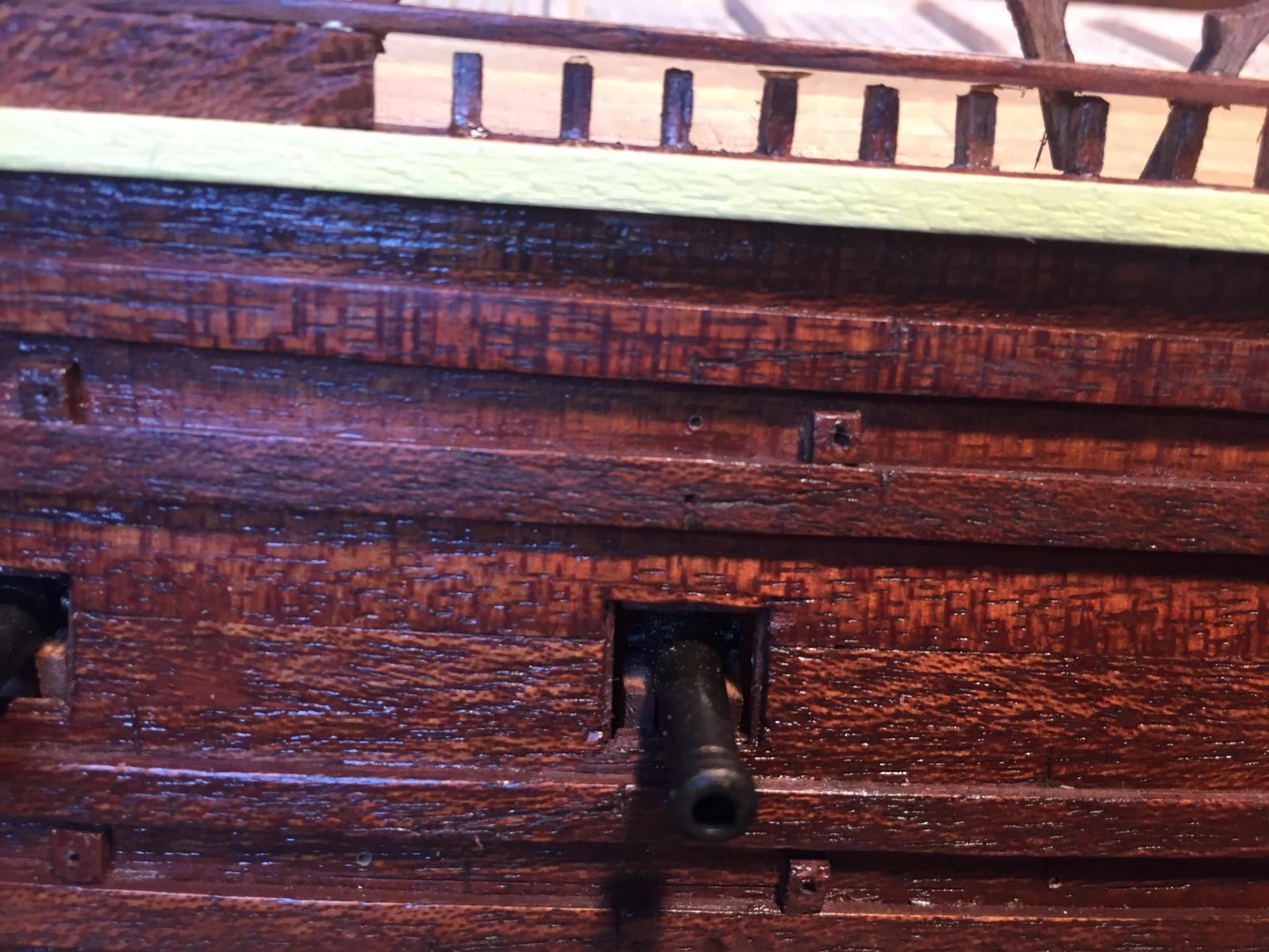
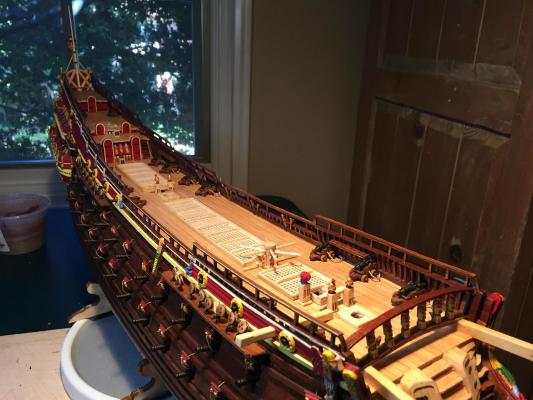
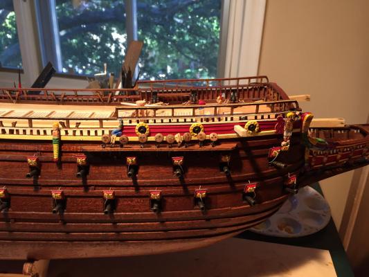
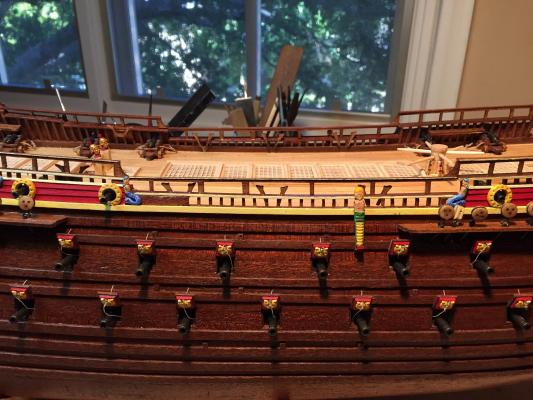
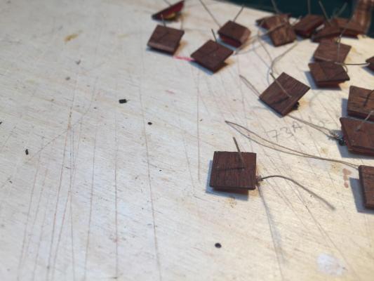
Time for the gunport lids. I wanted to display the lines used to open the ports as well as those to close them. For this I brushed a length of thin rope with a 50/50 mix of white glue and water and hung it to dry with some tension on it. I then cut short lengths and inserted them into a small hole on each port lid. I'd already drilled slightly larger holes in the hull, so all I needed to do was insert the other end of the line into the larger hole while attaching the lid to the hull with CA glue. The lines used for closing just get tucked into the open port. The result looks quite nice, and the port lids look suitably imposing.

- 249 replies
-
- 3
-
-
- billing boats
- vasa
- (and 1 more)
-
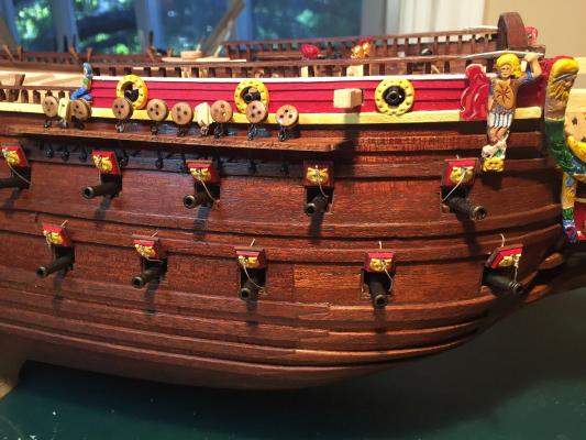
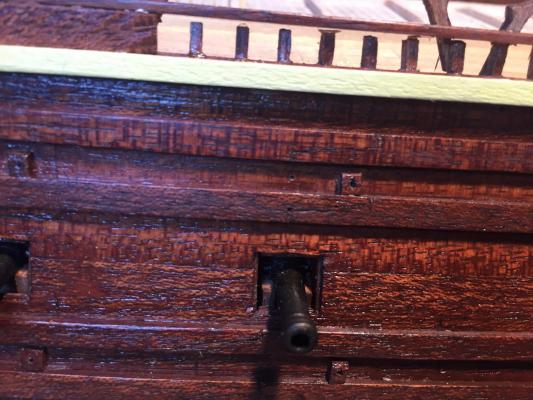
The gun deck cannon are from Amati, and replace the badly designed gunport/cannon setup provided by the kit. I sprayed the cannon flat black, then overlaid it with dark bronze. Fixing the cannon to their false carriages (thick CA glue) wasn't too difficult, I just had to make sure none of them fell into the hull.


- 249 replies
-
- 3
-
-
- billing boats
- vasa
- (and 1 more)
-
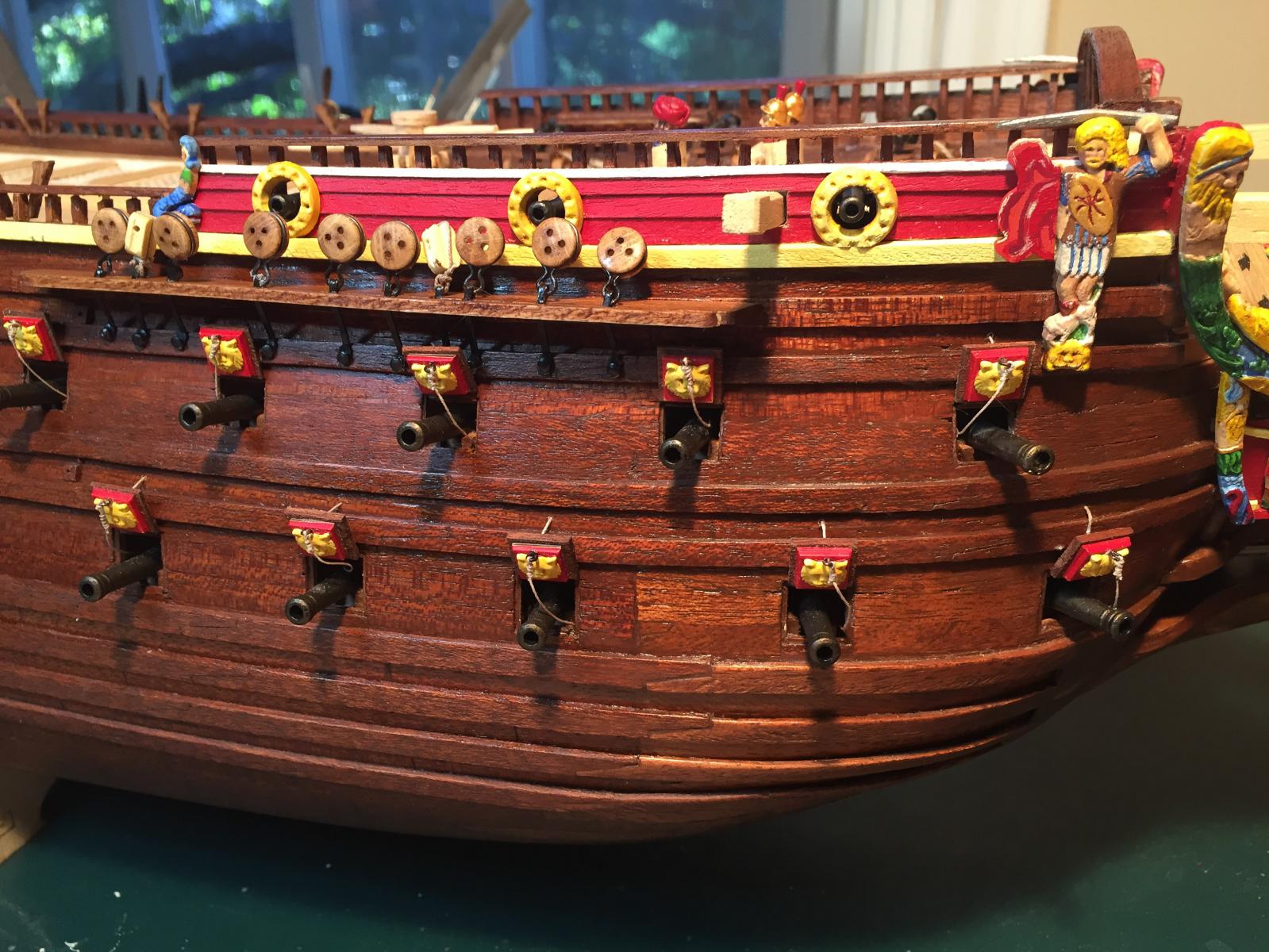
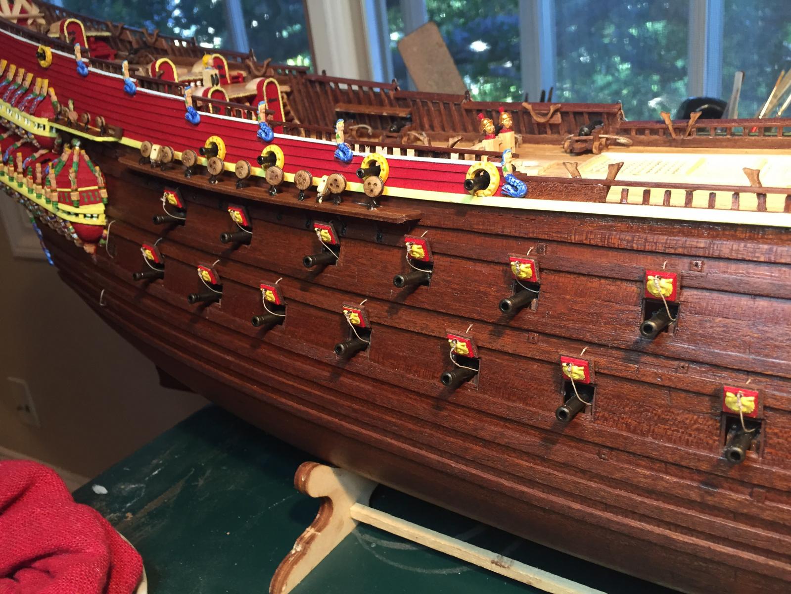
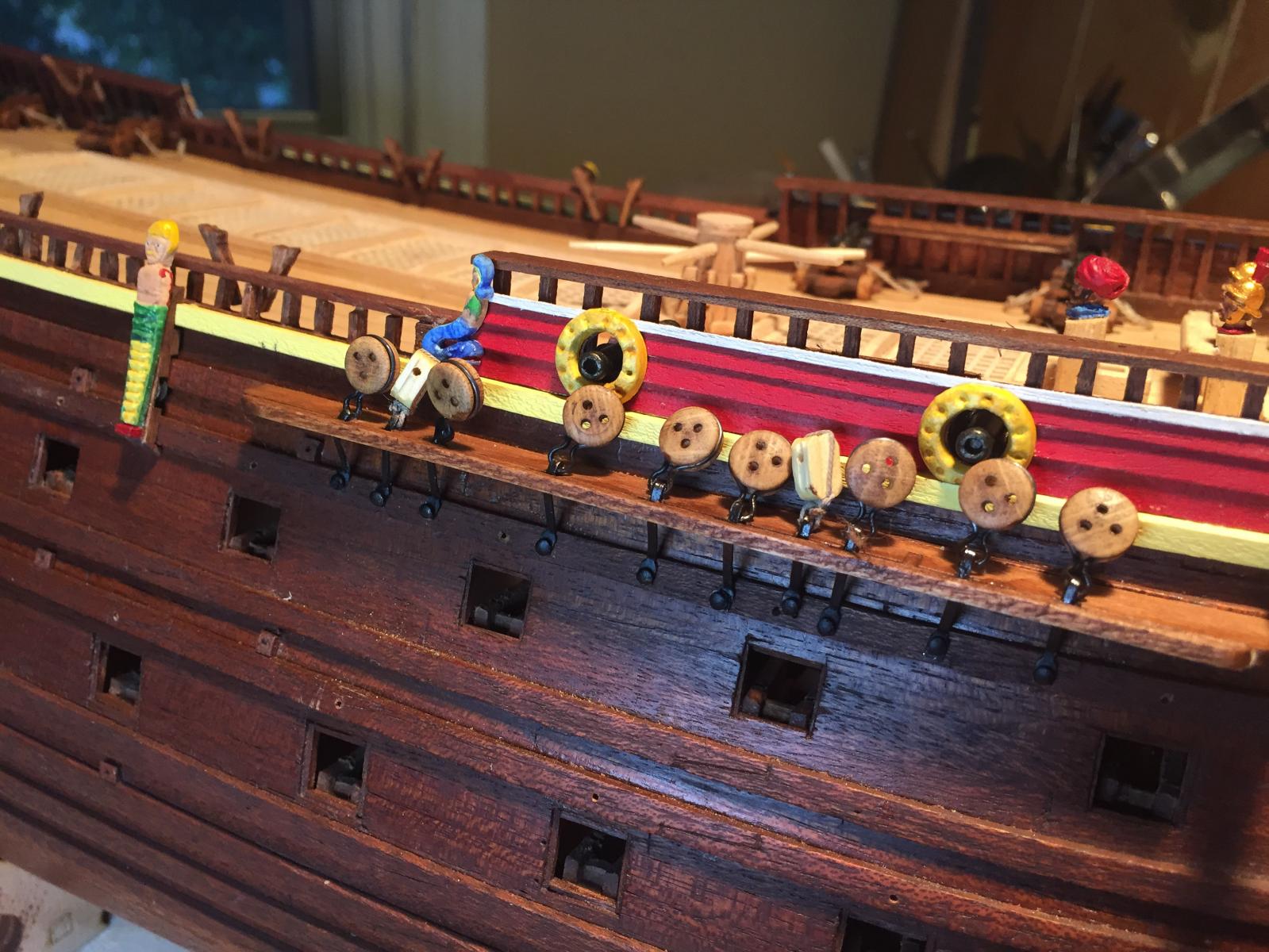
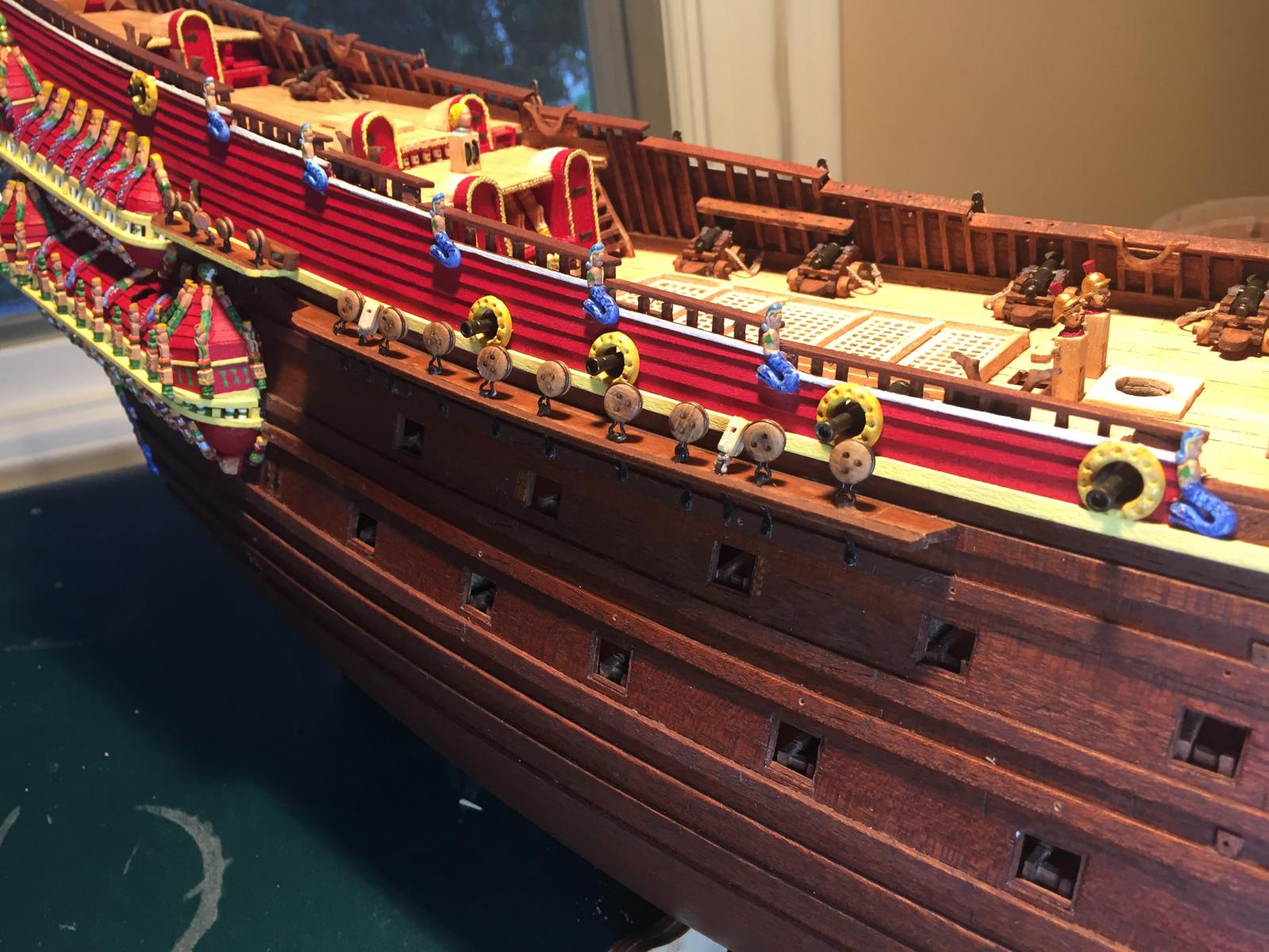
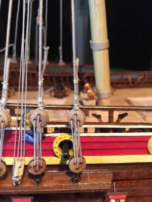
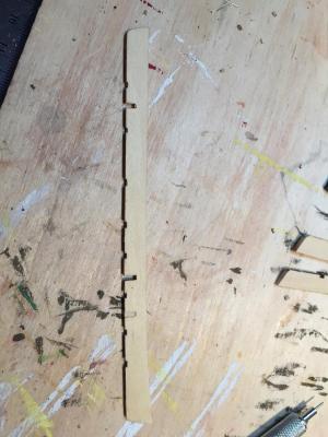
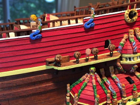
I've been a bit busy with high school graduations and vacations, but I've managed to spend some time working on the ship. Here are some photos of the channels and deadeyes. They were reasonably straightforward, with a few caveats. First, the deadeye notches on the foremast and mainmast are slightly off - the plans show extra notches, and two are in the wrong place. The first photo shows the filling in of a notch and its replacement in the correct location. Here's a photo of the mizzen channel. Rather then use thread to fasten the deadeyes to their chain plate, I used Amati metal strops. I took a brief look at making the deadeyes vaguely triangular in shape, but I decided not to. It was just going to make the strops hard to fit, and my fingers kept getting in the way when I tried to file them down. Hats off to Matti for persevering here! Also note the block in the middle. I'm using aftermarket blocks from Syren since they look better. The plans specify double blocks, but they should be singles. The kit-provided chain plates were simple strips of brass. I blackened them chemically, then used various jigs and small pliers to bend them into shape. The brass is fragile and work-hardens, so get the bends right the first time. All in all, tedious, but straightforward. Attaching the channels required a bit of fettling to get the angle of the channel correct, and required some filler to close gaps where the channel curve didn't quite match the curve of the hull. Again, nothing unusual, and the result looks fine. Care needs to be taken in positioning the channels so the deadeyes don't obstruct any gun ports. This was not difficult, just needed to be done. Here's a photo of the fore channel with all the deadeyes attached. It's very helpful to dry-fit the main mast and tape a thread to the top. Then you can run the thread down to the chain plate and make sure it's aligned correctly. And finally a photo of the main channel. While it may not be clear from the angle, I managed to avoid obstructing the gun ports. Next, the gun deck cannons and port lids. Getting near the end of the hull work!


- 249 replies
-
- 6
-
-
- billing boats
- vasa
- (and 1 more)