HOLIDAY DONATION DRIVE - SUPPORT MSW - DO YOUR PART TO KEEP THIS GREAT FORUM GOING! (Only 13 donations so far - C'mon guys!)
×


dashi
-
Posts
248 -
Joined
-
Last visited
Content Type
Profiles
Forums
Gallery
Events
Everything posted by dashi
-
 Thanks Jud I'm happy to go with your cad calculations as my eyes aren't too good and play optic tricks on me from nurve damage that glasses can't compensate very well.
 -
Jud and Druxey here is my calculation for 1/4 which I hadn't bothered with in my previous post. It shows this variation a bit clearer. 32.5+51.5=83mm I'll edit my previous post to include this calculation. Can you please confirm this Jud?
-
Thanks Jud I think we have a working theory. Druxey these variations became apparent in my calculations as shown which I was expecting to see. As we know Pollard solved this in 1771 so until then each helm would have had more 'character'. These variations can be smoothed by varying the diameter of the drum in different places to take more or less rope per turn which we have evidence of. From my understanding Pollards invention keeps the helm tension linear throughout the entire sweep of the tiller therefore eliminating all this jiggery pokery of the drum and tackle for larger ships where the tiller and it's support sweep could be fitted beneath the quarterdeck. As for the helm of vessels slightly smaller but requiring a wheel where a long heavy tiller was on the quarterdeck then this is the problem we are attempting to workout.
-
Several hours later and I try the next position as suggested by Jud... Thanks, following your idea has found a workable solution to the helm slack exactly like you prophesied. Here are my measurements of the helm rope between the starboard and port tiller blocks at varying degrees if I move them 2.5 mm or 2/16" @ 1:64 scale aft of (their previous position at the bulwarks) the line at right angles from the tiller head. This brings the helm ropes to almost touch the (what could have been wood chimney cowl) at full over. My calculations suppose the tiller arc being only along the horizontal plane or sweep and does not include a vertical arc created by the angle of the rudder post relative to the level of the deck. Centre: 42=42=84mm 1/4: 32.5+51.5=83mm (added from my later post #79) 1/2: 61+22.5=83.5mm 3/4: 71+13=84mm Full Over: 80.5+5=86mm As you can see only 2mm or approx 6" at 1:1 of slack is created after 3/4 Full Over which I think is a very workable solution. Could someone please check this incase I've made an error (which I'm prone to do)?
-
Thanks Jud. Had another look at how the block position opposite the tiller head affects the helm rope tension. Lengthening the block ropes didn't solve the tension problem. I put my good glasses on and made some more precise measurements and it appears that from the centre to hard over gradually introduces 1 ft of slack to the helm rope. Back to the drawing board to try Jud's suggestion of running closer to the chimney cowl.
-
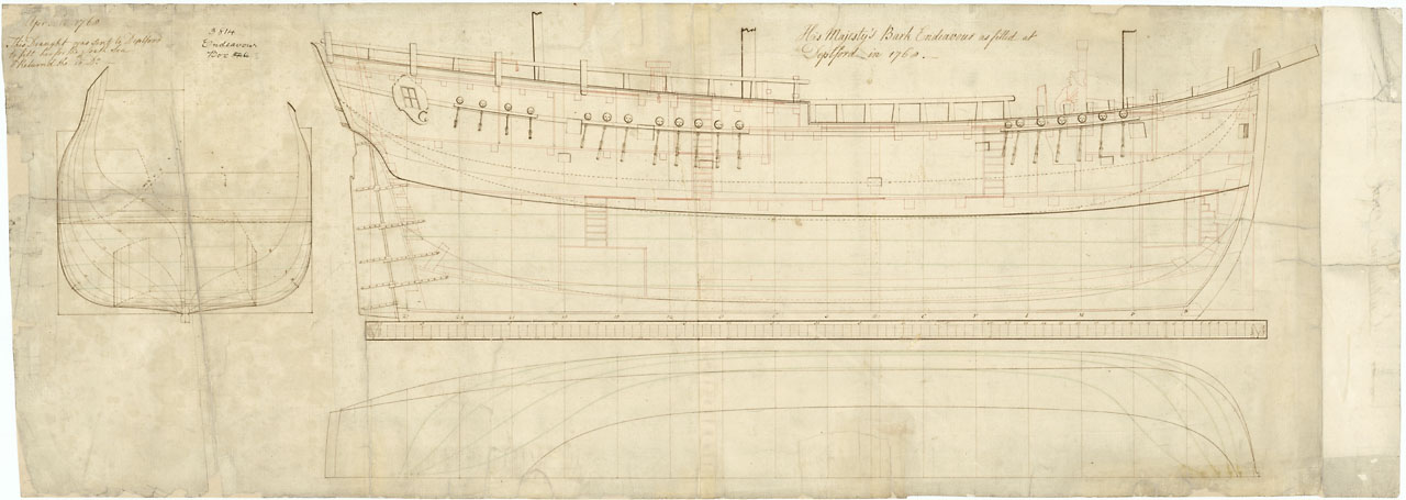
Hi Chris, good questions. Previous post numbers 24, 27 and 64 have profile or sheer technical drawings from 1668 and all show the tiller as it is with the metal uplift on the end to clear the chimney cowl from the great cabin. It's length with metal uplift matches the what is given in the AOTS book and the Caldercraft Kit. It can all get a bit confusing as I've found, because the post 1668 refit plan has the fire and chimney with tiller and metal uplift, but I'm not sure about the tiller brace, whereas the pre refit drawing of 1668 doesn't have the fire with chimney but still has the tiller and uplift as is, with tiller brace at the rudder head. The AOTS book has the fire and chimney but they have forgotten to include that on the drawings relating to the helm tackle which would slice through the chimney cowl if it were there? I'm building the Caldercraft 1:64 scale Endeavour and it doesn't even have the great cabin chimney cowl and so follows the AOTS helm tackle rig which crosses over where the cowl should be when hard to port or starboard. To avoid the chimney cowl the helm rope needs to be forward to a position at the bulwarks in a line at right angles from the end of the metal tiller uplift. Using just one set of blocks and lashing the helm rope to the tiller head via lanyards I've worked out that this configuration introduces tension to the helm robes when the tiller is moving close to port or starboard. I'm still working on this but it might be correctable by adjusting the length of rope anchoring the blocks at the bulwarks. I find it's easy to forget the scale of things when looking at drawings and building the kit so I've made a 1:64 scale ruler. I've marked at 1ft intervals which translates to 3/16 of an inch per interval. This helps me keep everything in perspective. There probably is a rule somewhere regarding the ratio of tiller length to rudder and hull size. I came across a topic regarding the attachment of tillers to rudder head (which I can't seem to find) and it mentions something about the way the french did this but no drawing. However the description seemed to match the drawing of our tiller brace. I think it might pass over the rudder head and down over the aft tiller protrusion where a pin through the protrusion holds it and the tiller in the head. But I'm not sure I've got that right and need to find more information. But having the this brace could make sense if the helm tackle is introducing a forward pull on the tiller.
-
I've done some calculations as to the possible weight of the 18 foot wooden part of the tiller if made from oak. I am not an engineer but I've got a figure of around 280 pounds - 320 pounds 130 - 150 Kgs. I'm not sure what the replica tiller is made of but someone mentioned in an earlier post that it might be made from a laminate or it could even be composite which have a much better weight to load ratio than hard wood and therefore wouldn't need the same level of bracing and support. I read that laminate can be as much as 50 to 200% stronger. So until someone can confirm the specification and material of the replica tiller then references to it may not be relevant to answering this question for the possible need of an above deck tiller support at 2/3 rds along it's length. Another consideration is if the helm tackle were to break then with out some form of stops you would have a 300 pound metal tipped 18 foot pole crashing into the deck and bulwark possibly in rough seas. As for the abaft fire flu according to Lawrey's book its possible it is a wooden cowl with a swivel top the same shape and size as on replica. But the helm tackle would still need to clear it.
-
Jud thank you so much for your time and input to this discussion. Just had confirmation of the aft chimney so the steering ropes have to clear that. Shipaholic thanks for this but you posted a similar plan to this earlier and it doesn't have the chimney or fire which I was also referring too. Could you post this recent one again but with a wider view from rudder post to wheel? The chimney is back in so I can't rig it per the Caldercraft rig as the steering rope will foul the chimney so looks like it will need to be made off as in the replica - via lanyard lashing to the tiller head. Robin I hope your house restoration goes well. I guess at the end of the day as Jud says, the physics don't change so eventually I'm going to have to weigh up the evidence to hand and make a decision as to that. lavery's book corroborates the common use of a sweep as a tiller support for steering gear below ships decks and above decks on smaller vessels that are of a size to require a long heavy tiller with wheel such as barks etc. The sweep has been in use since the time of the whipstaff from the 1600's. The only Bark Endeavour deck drawing to show the tiller also shows a sweep but with no evidence as to whether it is part of the 1771 refit or an existing part of the tiller gear from earlier. All other deck plans to my knowledge don't show the tiller so why would they show the sweep? The physics supports the use of a sweep for removing the horizontal arc of the tiller and it's contribution to the slack problem. The position of the blocks is critical to reducing the slack problem but didn't alleviate it until Pollard 1771 ran the rope around the sweep because according to him, there had been fatalities from the slack allowing I assume the rudder to whip back and take up the slack with such force to the wheel it had thrown the helmsman overboard. I definitely can't say I am certain about a sweep being used on Cook's voyage, but there appears to be corroborating evidence in favour of there being a need, and common practice for the installation and use of said sweep on vessels of the size of HM Bark Endeavour. That's all I have go on for now until I or someone comes across some more factual evidence which might help clear things a bit more. So thanks again everyone for a great discussion which I for one have learned a great deal from.
-
Thanks Robin, we could do with those plans if anyone has them. Jud, I've taken a closer look at the plans and see it has an 18" drum so with doubling the blocks I think you could get away with 7 turns. However I've been drawing lots of lines all over the deck trying different things and don't think a double block configuration will take out the slack, but it would half the torque at the wheel maker for a much lighter helm. As for that chimney I can't find it or the fire place marked on any of the 1768 or 1771 plans and have only seen it on the replica and AOTS plans so it's presences needs verification. From drawing and rubbing out lines all over my tracing of the quarterdeck what I found was that the position of the blocks on the bulwark is critical to reducing the helm slack. However this is a compromise compared to Pollard's method. So to find the position of the blocks draw these lines; one at right angles to the tiller head when at top dead centre to the bulwark; one from the rudder head at 25 deg to the centre to the bulwark; the arc of the tiller head from TDC to the bulwark. Now measure the distance between where the tiller arc line and the first right angle line cross the 25 deg line. Half this distance and take that mark to the bulwark which should give you the anchor point for the block. To check mark several positions along the tiller arc and measure the distances from the tiller head to the SB block and tiller head to the Port block and add these. If right then they should all be equal. This needs verification.
-
Jud I can see how that might work as it balances out the math because of running the helm ropes through blocks on the bulwark and then blocks on the tiller head and then aft to the tensioning blocks at the bulwarks again (at least that's what I think but not sure). I've just done the math for the drum and instead of 5 turns on the helm drum if the rope were lashed to the tiller head, you would need 9 turns because you have doubled the robe needed for the full movement of the tiller. This in turn would affect the steering by making it twice as light and half as responsive, meaning the helmsperson would need to turn the wheel twice as much to get the same angle of turn at the rudder. I don't know if this would be a good or a bad thing? Another thought I got from looking at old pictures of helm drums last night was that some of them are concave. It has just occurred to me now this would help take up slack that might be produced on the side the tiller is moving to as the rope from that side is wound on the drum. The side that is wound on would run up the concave taking more rope per turn compared to the side that is winding off as it runs down the concave realising less rope per turn. But you would need to know how much slack to expect from a parallel drum in that situation and then you could work out how much to concave the drum. At least that's the theory that just popped into my head, so who knows if it's right?
-
Wow this is great. Thanks Robin and Joel for mentioning those books. From what I can glean, the sweep was in use since the whipstaff and carried on with the use of the wheel as a tiller support whether above or below the quarterdeck and Pollard refined this idea in 1771 by inventing a system where the rope followed the sweep thereby solving the problem of slack in the steering ropes. Pollard did not invent the sweep. According to 'The arming and Fitting by Lavery' as mentioned by Robin a sweep following the arc of the tiller was commonly installed on the quarterdecks of smaller vessels that employed a wheel (or or maybe whipstaff) where there wasn't room for a heavy tiller and sweep to fit under the quarterdeck well prior to 1771. In this situation it was fitted 2/3 rds of the tiller length forward of the rudder post primarily as a tiller support where a heavy tiller (which I assume due to the size of the vessel couldn't be operated directly) was rigged to a wheel as in the case of the Bark Endeavour. The sweep on the 1771 drawing is for this later purpose and I don't think related to Pollards design. Not only that but I think the physics of having a sweep provided a minor solution to the rope tension problem by removing the arc produced by the angle of the stern post imposed on a rigid tiller. Which brings me to the purpose of the tiller brace which I now don't think was there to form a rigid connection to the rudder post but instead to help brace a pivoting connection needed for a heavy tiller to ride on the sweep as intended. How exactly the tiller brace did this as yet I haven't figured that out but am working on it and have some ideas and hopefully more research will reveal something.
-
HMB Endeavour tiller measurements from the AOTS book: Full length from projection aft of rudder post including gooseneck: 21 feet Aft projection to forward side of rudder post: 2 feet From rudder post to end of wood (gooseneck connection): 16 feet Iron gooseneck: 3 feet Rudder post to end of gooseneck: 19 feet Postion of the quadrant or sweep on the 1771 draft from rudder post: approx 11 to 12 feet or 2/3rds along the wooden part of the tiller. To summarize thus far: I think we are still in need of more information because: We can assume that the steering gear is part of the 1668 refit as it is drawn in red on the pre-refit draft. This profile draft dosn't show the sweep, but as Robin points out this is also the case in at least one other ship. On this pre-refit draft what might be a brace drawn in red can just be seen connected to the top of the rudder post to forward to the tiller, but is not seen on the post refit draft of 1668 unless someone has a better copy and can see it? The sweep and tiller are not drawn on the plan drafts of 1668. This means the absence of the sweep in these drawings dosn't mean it wasn't there. Other ship drafts of this era don't show the tiller either so their absence on the drafts is not uncommon. Cooks log indicates that the tiller braces were repaired twice in October of 1769 and January of 1770 when he was navigating New Zealand. The 1771 Woolwich draft has the tiller and sweep but they are not drawn as additions which means the sweep could have been existing as we know the tiller hasn't changed from the 1668 drafts. The even rope tension needed for this steering configeration is provided by use of a sweep. But we don't know how they keep an even rope tension on the replica? Have I missed anything?
-
Something to consider if I've got this right? The steering gear is a combination helm and tiller above decks using block and tackle wound around a drum attached to the steering wheel. The rope would need to remain under a constant tension for this to work right? There is no where apart from the lanyard lashings of the rope to the tillers goose neck to take up the tension from what I can see. You cannot have any blocks on the tiller because of the chimney which I assume is the reason for that gooseneck on the end of the tiller. Now I see a problem with a rigid tiller to rudder post attachment with this configuration because at 21 ft the tiller will follow a large arc governed by the angle of the stern post. This arc of the tiller would affect the rope tension differently as it moves through the arc during steering. When the tiller is mid way between port and starboard then its at its highest and would put the most tension on the drum rope. But at port or starboard the rope would be slack and the steering sloppy or not possible. The rope would be constantly slackening and tightening with every movement of the wheel which is not desirable I'd imagine. I don't know how they get around this problem on the replica unless the lanyard lashing to the gooseneck is a bungy? A sweep with pivoting tiller would be a solution because it can be built to allow the tiller to move relative to the deck and tackle thereby maintaining an even tension throughout steering. When the rope slackens over time then it can be taken up by the lanyard at the gooseneck. Does this make sense or have I got it terribly wrong?
-
Hmmm. If the iron brace is used at the rudder post as drawn in red on a 1768 draft then the tiller wouldn't be able to ride along a sweep because it would be rigid along its vertical axis at a fixed angle relative to the rudder. Therefore if a sweep were used to support the tiller then the tiller to post joint would need to swivel on its vertical axis so the tiller can ride the sweep making the iron brace redundant and the sweep would then be the tiller brace... I think?
-
Cheers Robin, you are a champion for opening up your studio for us and providing that info. Steve I'm intrigued by the top close up which shows some good detail of the tiller and especially how it connects to the rudder post with a brace like on the replica. Interestingly the tiller seems to leave the post close to the deck and curve upwards to the gooseneck which looks to have two small holes through the nob on it's end (I could be mistaken). And importantly there is no sign of a sweep on this draught. Thanks Cabbie and Frankie for find those good shots of the replica tiller and the info that it is composit laminated wood which could explain why it dosn't curve and why it inturn connects to the rudder post slightly higher than in the draught of 1768 put up by Steve. I feel like we are getting somewhere with this. Some more 1768 draughts showing different profiles and detail would be helpful if they are out there. The evidence we have uncovered so far is in my opinion now leaning in favour of the replica steering gear being the most accurate with the exception of the uncurving laminated tiller with the possibility of sheeves instead of blocks as has been suggested earlier. Possibly due to two noted breakages of the tiller brace a redesign was prompted for the 1771 refit which replaced the tiller brace with a sweep two thirds down it's length as shown on the 1771 Woolrich draught? I'm interested in what others make of this, cheers dash.
-
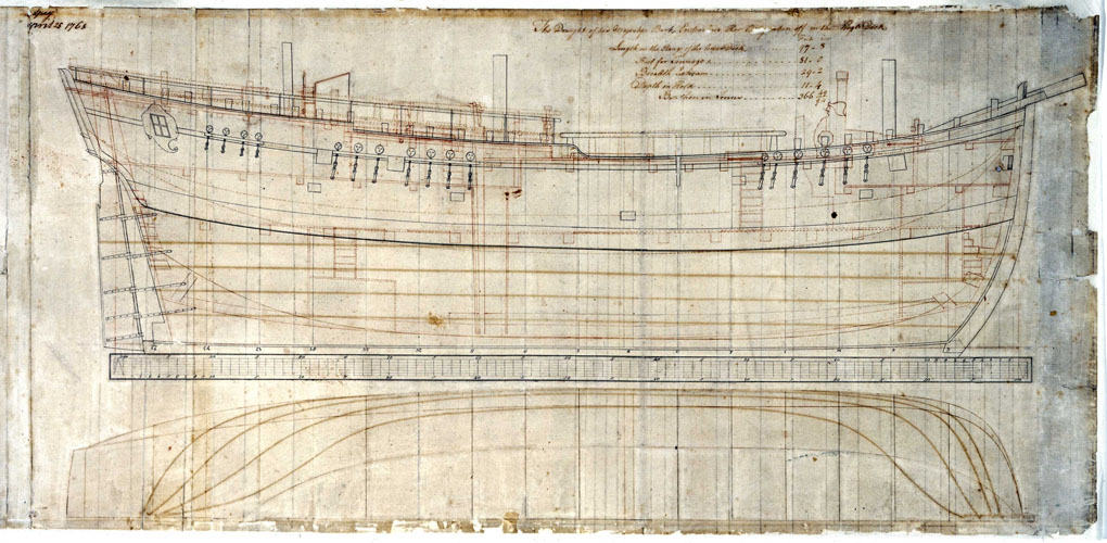
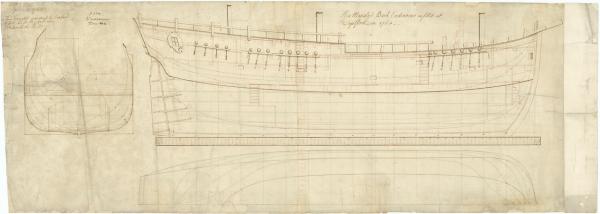
Look what I just found... It is dated 1768 and shows what I assume to be the Navy refit drawn in red. What is interesting is I think I can just make out a line going from the top of the rudder post down at 45deg to the tiller drawn in red along with a curving red tiller. If this is the case then it might support the metal tiller brace on the replica which is in this position and could in fact be the broken tiller brace Cook is referring too and not the sweep which I thought also possible. I cannot make out if there is or isn't a sweep under the tiller as the picture isn't clear enough. But I can also make out the orientation of the helm wheel aft of the drum drawn in red also. It seem the steering gear is all part of the navy refit. I wonder if somewhere there is a more detailed draught of the steering gear?
-
Thanks Cabbie for those links as I haven't seen these photos and they give some very clear shots to work from. Have you found any shots of the rudder post under it's little hood? I'm left wondering how much information is given in the Admiralty draughts and how much was just left out and presumed up to the shipwright and shipyard? But then I suppose a Navy refit would be a fairly structured affair and from the logs included some experimental kit such as the 'white stuff' on the pinnace. And thanks again to everyone I'm really getting a lot of useful information from this discussion even though there are still unanswered questions.
-
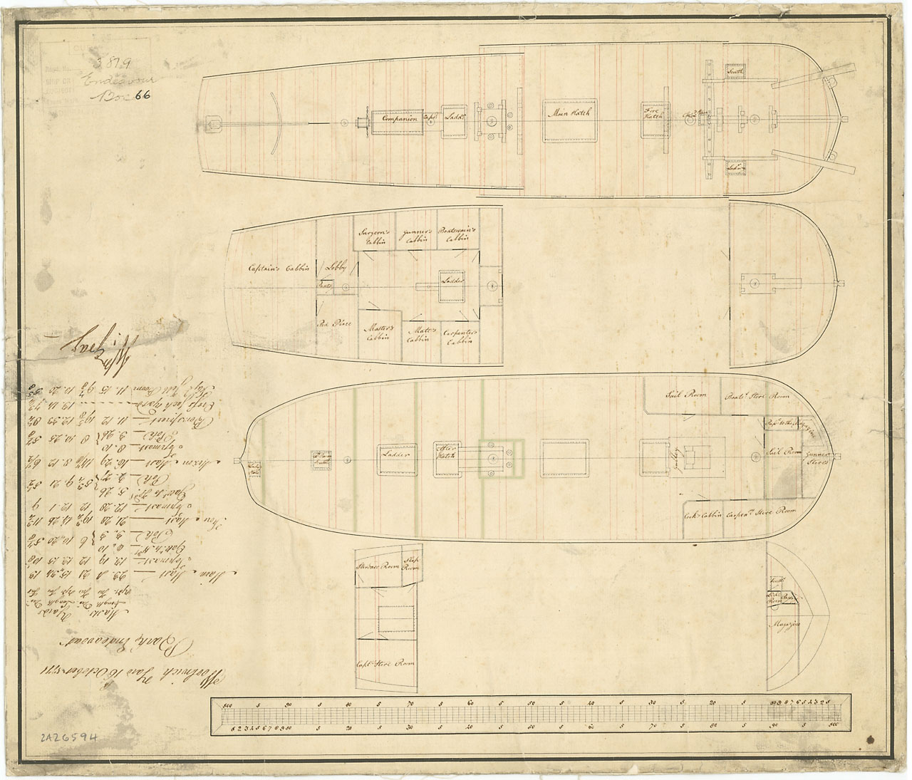
Frankie. According to the AOTS book the tiller measures 21 ft including the bent iron extension if I've read their scale of 1/8" to 1ft correctly. Is the replica tiller made from the same timber and therefore the same weight? What we are referring to as an arch, quadrant or sweep may in fact be the tiller brace Cook is referring which broke twice on his voyage and it would have been positioned 2/3rds the length of the tiller from the rudder post. If it were below decks then it would be drawn as a broken line following the way the draughtsman as drawn main deck beams where they pass under the quarter deck if you look closely at the Woolwich drawings. Also if the tiller were move to below decks then it would move forward on the drawings as the rudder angles under the keel which is clearly not the case with were it is drawn. It is drawn on the quarter deck fitted to the rudder post as it clears this deck with what I will refer to as an arched tiller brace supporting it. I'd imagine this brace would have stops to prevent over steerage and if a stop broke then this would require repair but wouldn't prevent the tiller from working. Druxey. I'm also thinking about the method of attaching this 21 ft tiller to the rudder post. If an arched tiller brace were used to bear the weight and considering the angle of the stern and rudder post then I'd imagine the simplest, most reliable and logical method of attachment to be floating. That is via means of a metal bracket and pin allowing for the tiller to ride smoothly along it's brace while only the steering stresses are at it's attachment to the rudder post. If it were a fixed attachment to the rudder post then the tiller would ride up in an arch over the deck like you say, adding undue stresses where it connects to the rudder post and also to the steering tackle. As for the height of this tiller brace that would also be influenced by deck camber and tiller bend but its ends are well clear of the bulwarks allowing for easy passage around it. According to the AOTS book the great cabin had a fire who's flu came up through the quarter deck right under the bend in the attached metal tiller extension which is just to the rear of the mizzen mast. This possible explains this bent metal tiller extension. As for the tackle I'm not sure but I'd imagine it could be hooked into the ring following the steering gear layout in the AOTS book or I see on the replica it is lashed to loops in the helm robe? But having a 21 foot tiller would reduce the strain on the steering gear and helm (but only if the tiller were well braced) making for a light helm. Also can you see which side of the drum the wheel is on? According to AOTS it is aft of the drum but in the above drawing dated 1771 it appears to be forward of the drum just to the rear of the skylight which makes more sense keeping it clear of the mizzen mast belaying?
-
Thanks Robin and everyone. Ok a little progress, it appears that our 'quadrant' is in fact called a 'sweep' and has a metal strip where the tiller arm rides on it which was kept greased. Sweeps were in use since the days of the whipstaff to support the weight of the tiller and give it a smooth sweep. So until I'm convinced otherwise, at this stage the evidence is in favour for the use of a sweep as shown positioned on the quarterdeck under the tiller to be historically and technically correct. Why it has been overlooked in recent years is a mystery as it would have been a critical component for this design. Without it the stresses on the 18ft (21ft with the metal gooseneck) long tiller where it connects with the rudder post would I imagine be a cause for frequent catastrophic failures, not to mention it's bounce would frequently slacken or break it's tackle. I am almost up to the rudder on my Endeavour build so unless I come across information to the contrary I will attempt to bash a tiller sweep on the quarterdeck. I've had a closer look at the 1768 profile and while the forward cooks oven and flu are shown there is no flu coming out under the tiller gooseneck from the great cabin? Another mystery or was the fire part of the 1768 navy refit, but if it was then what is the reason for the gooseneck on the tiller in the original build? Thanks again for everyone's input and if anyone finds any more information regarding the use and design of 18 ft quarterdeck tiller and wheel steering then please share it here. Cheers Dash
-
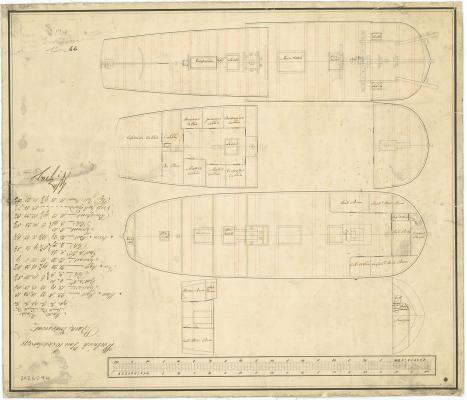
Thanks Druxey this is helpful. The dotted lines I was referring to are on the top drawing where the quarter deck overlaps the main deck. You can see the main deck beams are drawn in solid where exposed and change to broken when passing under the quarter deck structure and beams. You refer to the 'quadrant', is this the term for the arched tiller support? Thinking about it, whether below or above decks a long heavy tiller would require an arched support at around 2/3rds of its length. So I'm guessing it's uncommon to have such a large tiller above decks, but maybe not unheard of? It might help to see the tiller arrangement of other ships of this era and size. The iron cranked goose neck on the tiller was to clear the flu from the captains cabin fire. It would have been rigged via blocks to the ships wheel which is shown just forward of the mizzen. Maybe the tiller tackle on the replica is removed when parked so visitors won't trip over it? I also notice the replica tiller has a metal brace to help support its weight where it connects to the rudder. Another consideration is the steering tackle would pull down on the tiller as it clears above the bulwark height. Having a quadrant under the tiller would counter these downward stresses from the tackle.
-
Thanks guys but my curiosity is still not satisfied. I just rotated the drawings and discovered that the woolwich yard comments of 16 October 1771 are written on the drawing upside down relevant to the drawing and scale at it's bottom. So the rotation of the drawing is correct as uploaded and the top drawing appears to show the above deck fittings including the tiller and arc as you wouldn't include the odd below deck fitting on a technical drawing in a solid line, but instead it would be drawn in a dotted line which is the case for the main deck beams below the quarterdeck on the same drawing. The 1768 drawing doesn't even show the tiller or bumpkins, so with these details omitted then is it likely that the arc detail has been also omitted from the drawing? The tiller with iron end attachment on the woolwich yard drawings of 1771 matches the tiller with iron end attachment on the Navy refit build draught of 1768 further suggesting this is the same tiller in the same position above decks.
-
Thanks for this Joel. Do you or anyone have photos of this on a replica or more detailed technical drawings of it?
-
I have come across some old plans for HMB Endeavour which show an arch shaped object under the tiller. Can anyone explain what this is? I'm guessing it could have been marked with degrees for steering and or a supporting run for the tiller?
-
Thanks everyone for looking in on my build and the complimentary comments. Paul, I was looking ahead at the windows and checked out some ships galleries of replica's online and prefered the yellow ochre. I've pre-painted the frames so I can glue clear projector film to the underside for glass. Dave, thanks for the heads up on mounting. I'll be using the cradle in the kit but you have got me thinking about how to best attach it to the hull.