HOLIDAY DONATION DRIVE - SUPPORT MSW - DO YOUR PART TO KEEP THIS GREAT FORUM GOING! (Only 13 donations so far - C'mon guys!)
×


dashi
-
Posts
248 -
Joined
-
Last visited
Content Type
Profiles
Forums
Gallery
Events
Everything posted by dashi
-
 Looking good Mindi, glad you are back on board with your Endeavour.
 -
Cheers Mindi and thanks for looking in. Do you have a build log? Edit: Scratch that I've just found your log and your build is looking good. Looks like we are almost at the same stage. Cheers Dashi
-
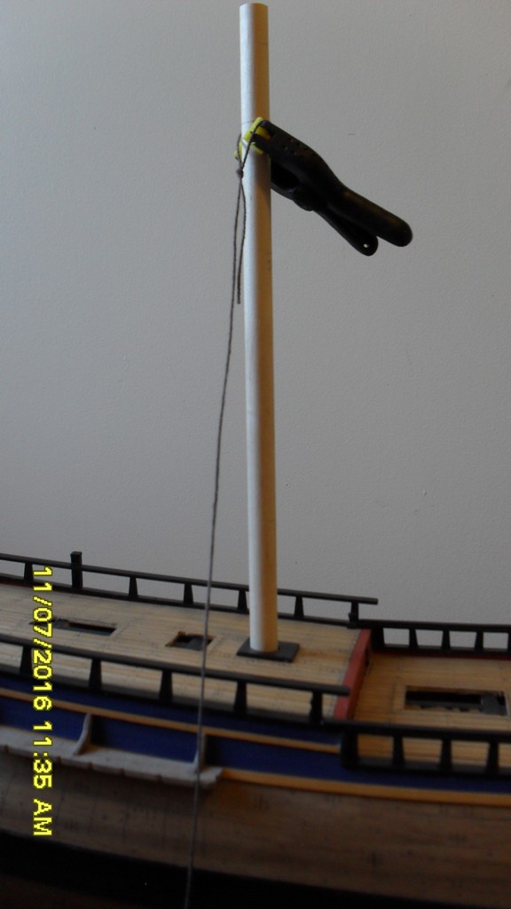
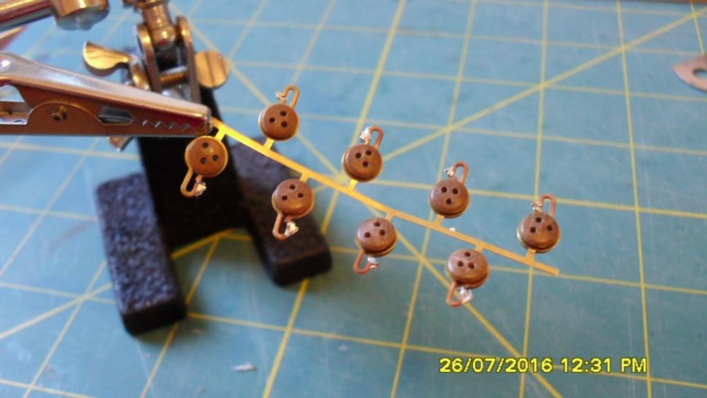
Thanks Dave and everyone for the likes. Will have to wait until I put the masts and shrouds on to find out if the plates line up or solder joints hold. cheers Dashi
-
Dave, I went and had a peek at the replica facebook page as you suggested and see they have taken the mizzen top mast and top down. You can see that the height of the mizzen standing mast from deck to top is too short for the top mast to clear the top when lowered via it's top rope, so it appears they had to use a crane to lift the top mast up through the top to remove it as Shardlow predicted in his report. I wonder if they are going to raise the standing mast and step it in the lower deck? cheers Dashi
-
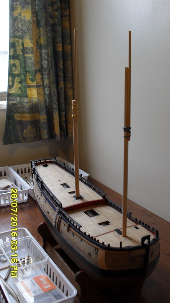
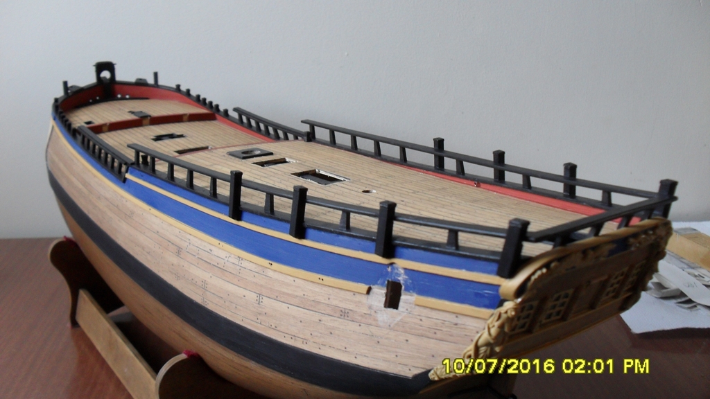
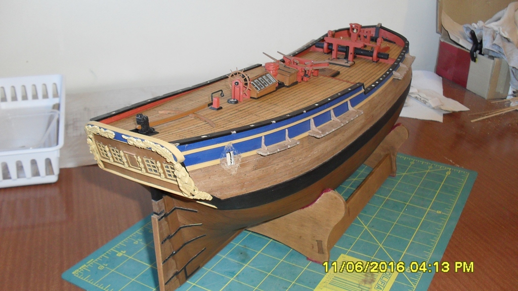
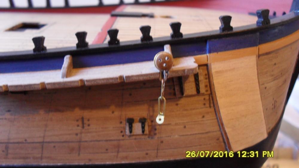
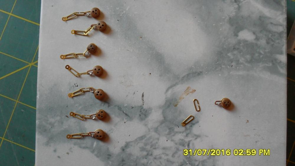
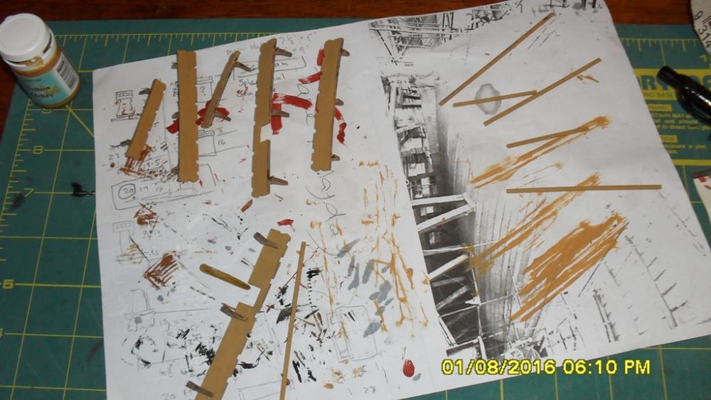
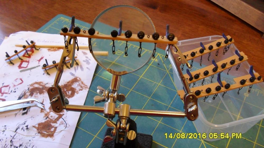
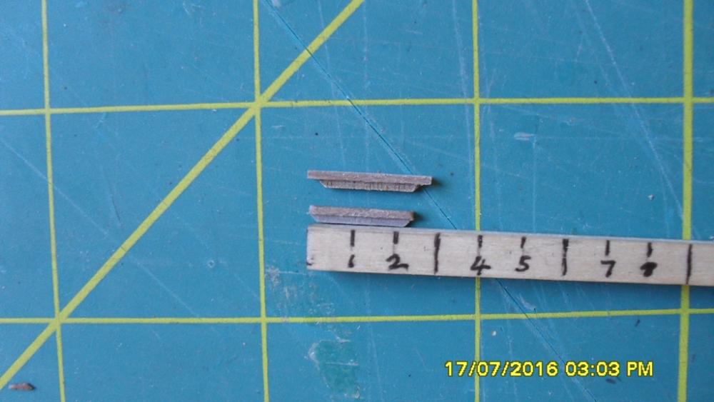
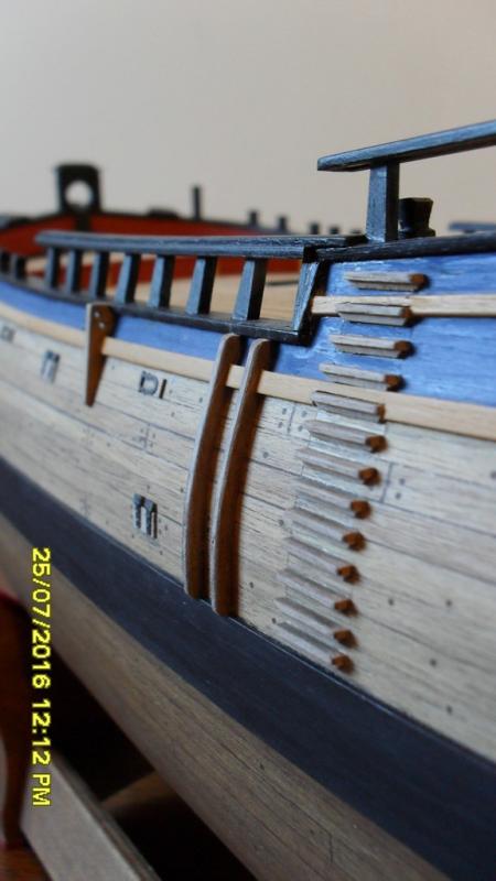
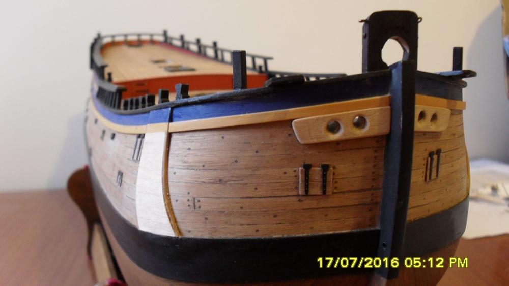
Glad that worked for you ca.shipwright :-) Update: Channels, chainplates, scuppers and quarter badge following the NMM 1768 as fitted draught. I used to the kit parts for the chain wales and chainplates with the exception of the mizzen. The mizzen kit channels and links were way too small so I bashed some replacements. The kit says to us ca glue for the deadeye brackets! I couldn't see how this would hold so soldered these and the chains instead. I mocked up the masts with a clamp at the height of each top and used a string to get the shroud angles for the chainplates. I thought it might be easier to paint the deadeyes first and then fit the chains into to the channels and glue on the retaining strip then paint the chains, seems to have worked ok. Channel eye bolts: These have been glued with a short tail bent over under the channel so they won't pull out under tension. Scuppers: I didn't like the kit or AOTS layouts for these and a little research revealed they were likely lead pipes running down at an angle through the waterway/deck out to the hull, possibly with leather spouts. I've positioned them where I think they would have been needed most including a pair midway along the quarter deck coming out just below the sheer strake. Not sure if this is how they were done, but they aren't marked on any of the original draughts so just my best guess. Quaterbadge and window were fairly straight forward. I've bashed some window shutters which I'll add later and used clear projector film for glass as I've done with all other windows. The plates look like they should have been only 6mm long instead of the kit supplied 10mm. Too late now to do anything about it. Today I was looking at the sketch of the larboard quarter of Endeavour by Sydney Parkinson (AOTS page 32) and noticed he has drawn the medium light port positioned abaft and just below the fore channels which has been left off the kit and AOTS draughts. As I've mentioned earlier it is drawn on the 1768 as fitted draught. Next is the lantern and then finishing the deck fittings, but I might take a short break before these as I have other things I need to do which means temporarily packing up the ship yard so I can use the table and space. Cheers Dashi


-
Looking good Dave. As to the mast lengths, Pat informed me that the AOS isn't accurate because according to Karl the author, the publisher altered the scales on some of the drawings. I don't know about the accuracy of corel plans but the caldercraft plans are full of scale inaccuracies. Cheers Dashi
-
Thanks for all the likes and cheers Pat. Thanks for looking in Dave. I have the yard busy with the chainplates and completing the channels plus repainting the main cabin window frames white. I'm using the kit parts for most of these except bashing the mizzen channels (shown in earlier posts) and chain links which were way too small. The mizzen top and main gallant back stays are shown hooked on eye bolts in the hull and sheer strake in the kit plans and AOTS. But this doesn't work in practice because they are then fouled by the quarterdeck rough tree rail. To fix this I may hook them into eye bolts through the channels, which is what it looks like they have done on the replica. I'm also not sure about the main lower stunsail boom attached to the fore part of the main channels according to the kit plans. Then when that's done I'll post some pic's and an update and it's on to the quarter badge and finishing the hull. Cheers all Dashi
-
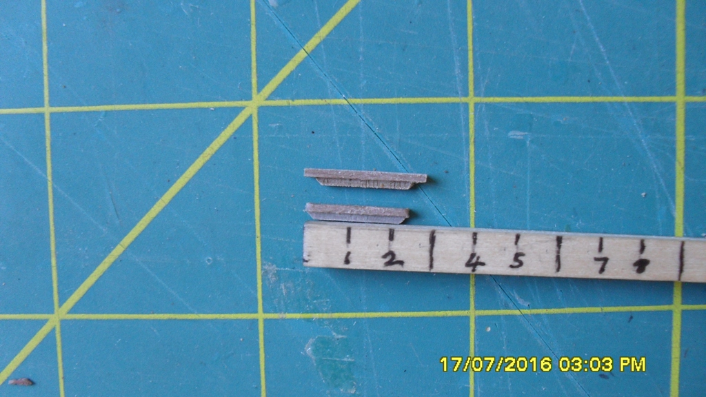
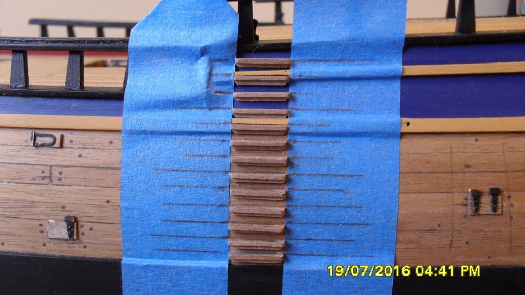
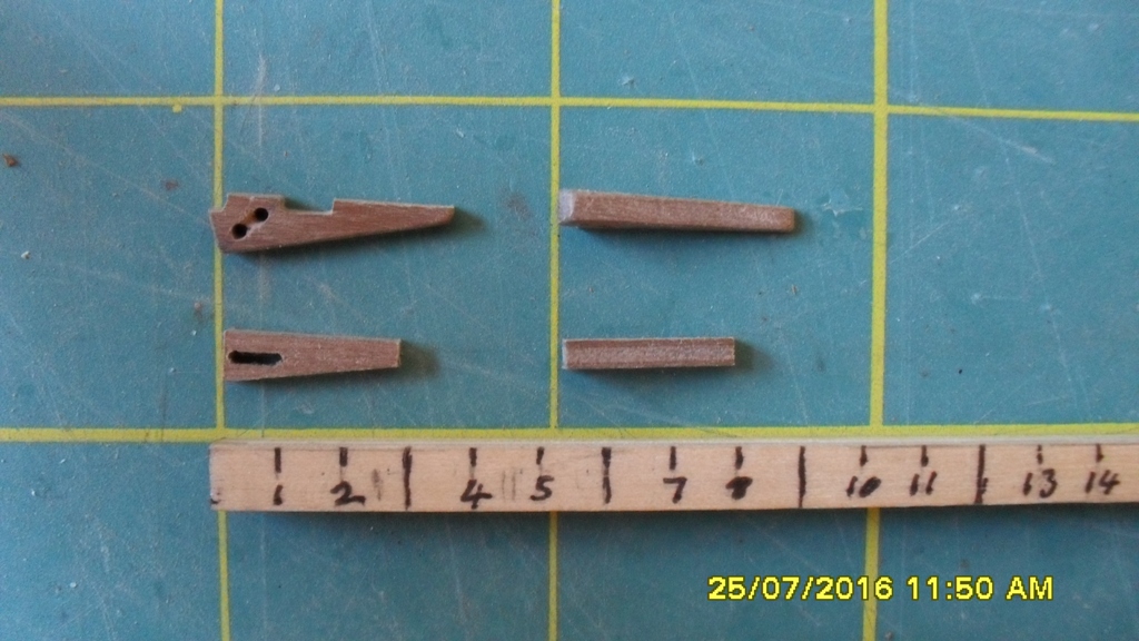
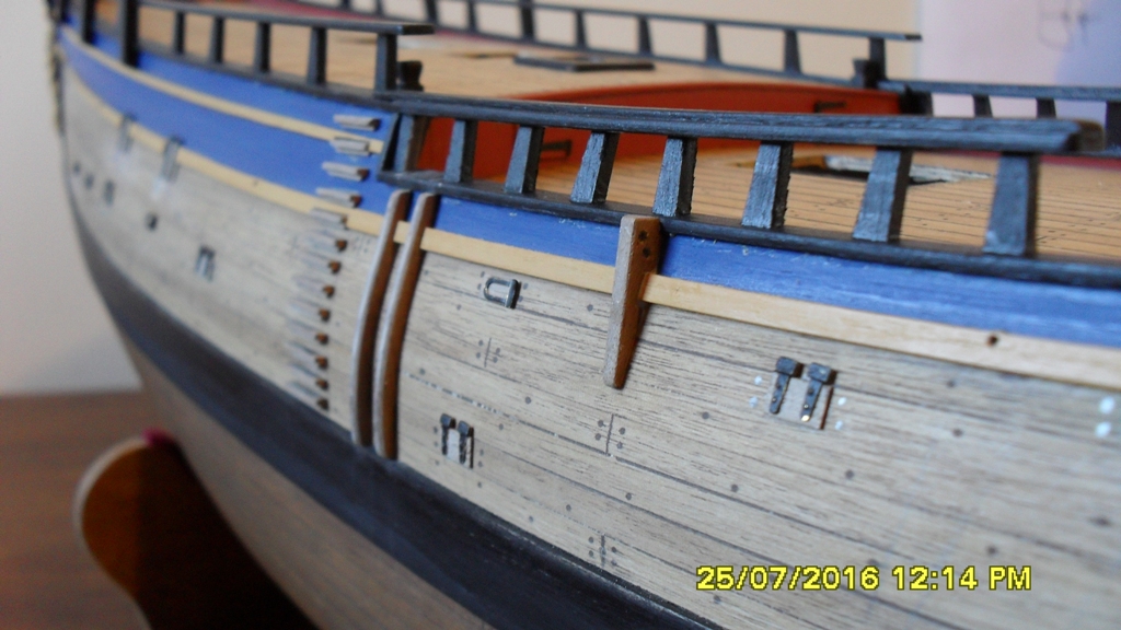
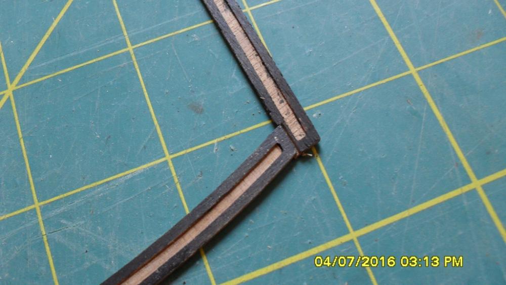
Thanks for the comments and likes. Hull fittings continued: Gangway steps, skids and main course tack chess trees. Trimmed the kit gangway steps width down to match the Navy draughts @ 2.5 feet. Marked the plumb or vertical line on the hull and fitted the top and bottom step then used masking tape for measuring and lining up the rest of the step positions. Each step needed it's back edge slightly bevelled to ensure it's upper edge was horizontal from the hull. Of course the shipwrights managed to knock a couple of the port lid hinges off while measuring (better we find the loose hinges now than later). The kit skids actually fitted after measuring and slotting the shear strake, but needed a little soak and pinning overnight to the form to the hull then rounding off. The kit chees trees were too short and narrow, while the kit plans had them too long when compared with the draught @ 3.5 feet with a slight tapper. Luckily the disused kit knightheads were the perfect shape, thickness and length after a little trim and tapering, so recycled and bashed these into the chess trees. Cheers Dashi


-
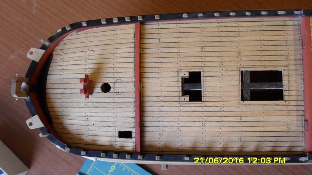
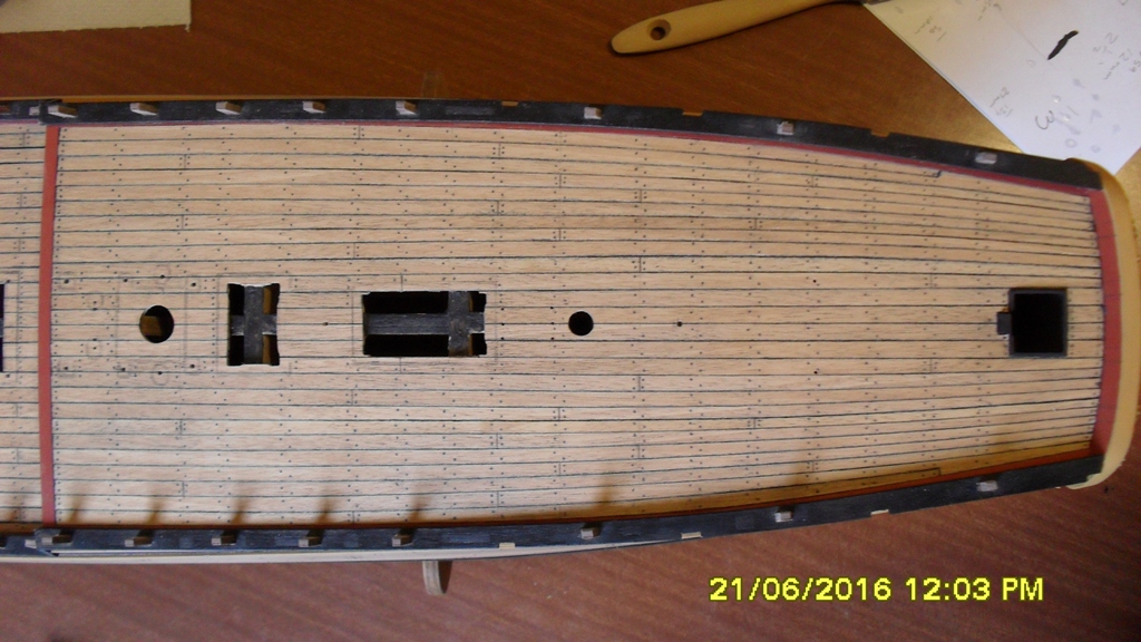
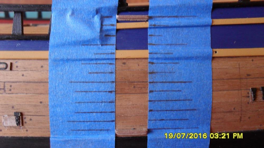
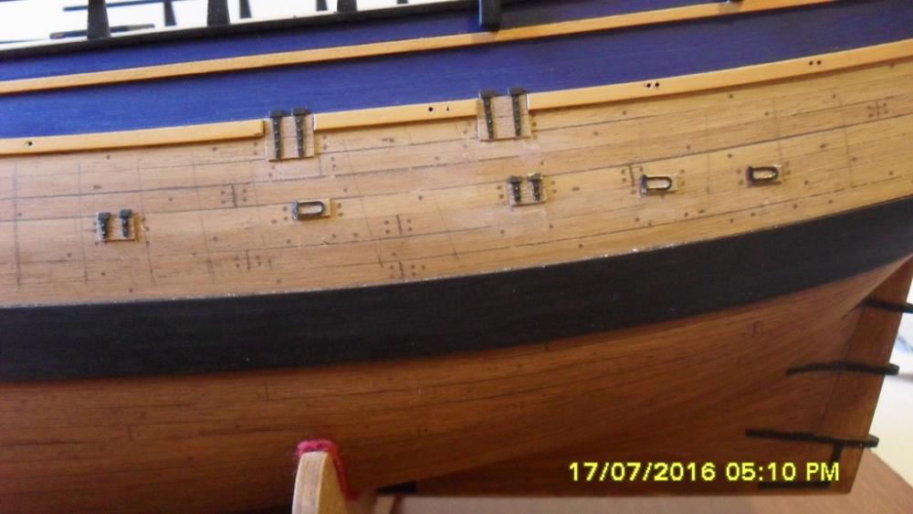
Hull Fittings Light port lids: First clamping a string to each mast at the height of the top and using a sharp very soft lead pencil I lightly marked the chainplate postions to ensure I didn't put a lid in the way. For the positions of the large and medium lids I used the NMM '1768 as fitted draught' zaz7844. For the positions of the small lids I used NMM draught zaz6587 because they aren't shown on the other draughts. Both the 1768 proposed and as fitted draughts have a medium lid slightly down and abaft of the fore channels and a large lid midway under the main channels which differs to the AOTS. I have removed a part section from the main channels to allow for this large lid which is my interpretation of the 'as fitted' draught. As I'd given the hull a coat of poly I needed to sand the position of each lid for the white glue to hold. So in total I have 15 port lids per side, 5 of each size. Blooper: I made the large lids several weeks ago and forgot I'd used the ca gel for the hinges so when I tried to glue the medium hinges on with the liquid ca it didn't stick very well and soaked into the wood. Silently cursing my stupidity I soaked the hinges off with acetone, cut some new medium lids and started again. Navel hoods were fairly straightforward requiring a slight soak and bend introduced to follow the hull. The horse holes have a downward curve and flare. The hull looks a bit rough at this stage which should eventually be fixed with a coat of poly after completion of the hull fittings. Now on to those steps... Cheers Dashi


-
Thanks for the likes and thanks Pat your boom fixes look good. Thanks Dave I like the work you have put into those ankors and cat heads with the crowns. Cheers Dashi
-
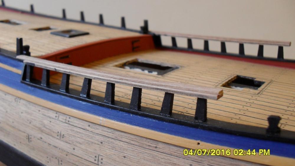
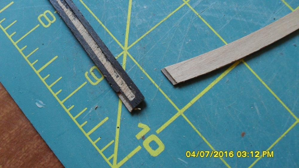
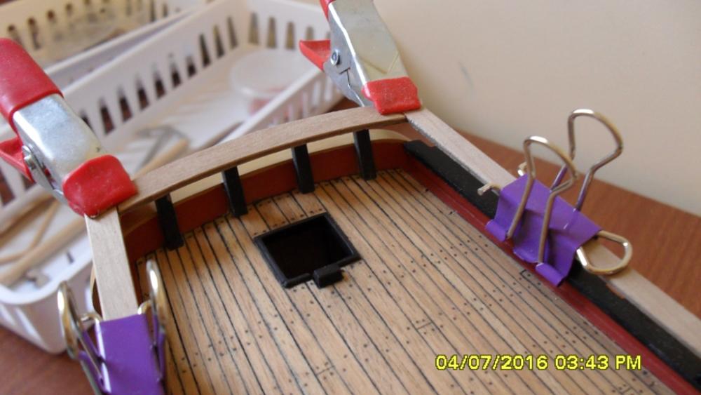
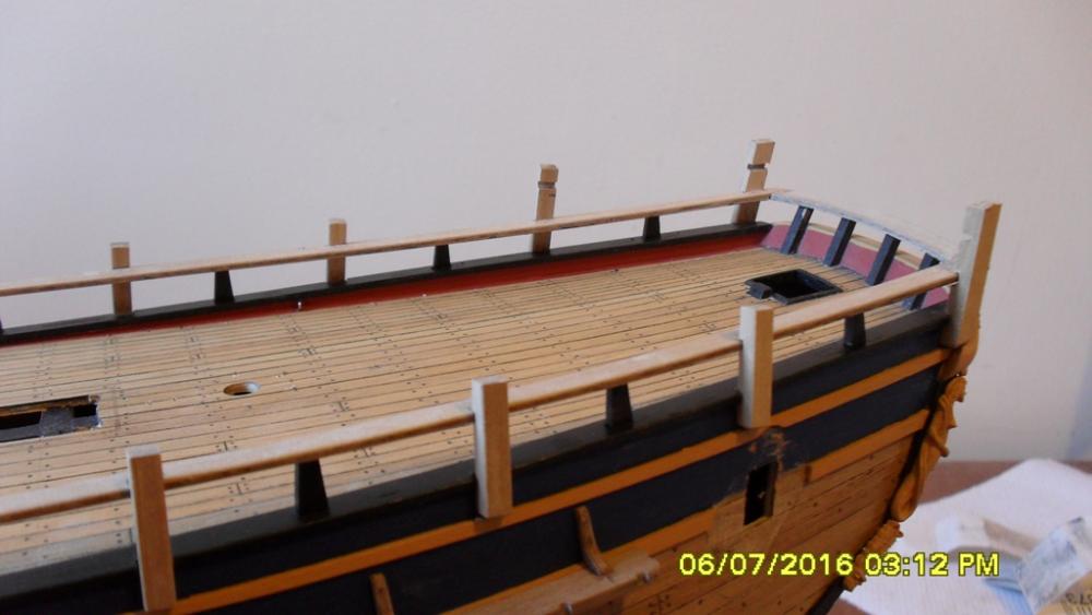
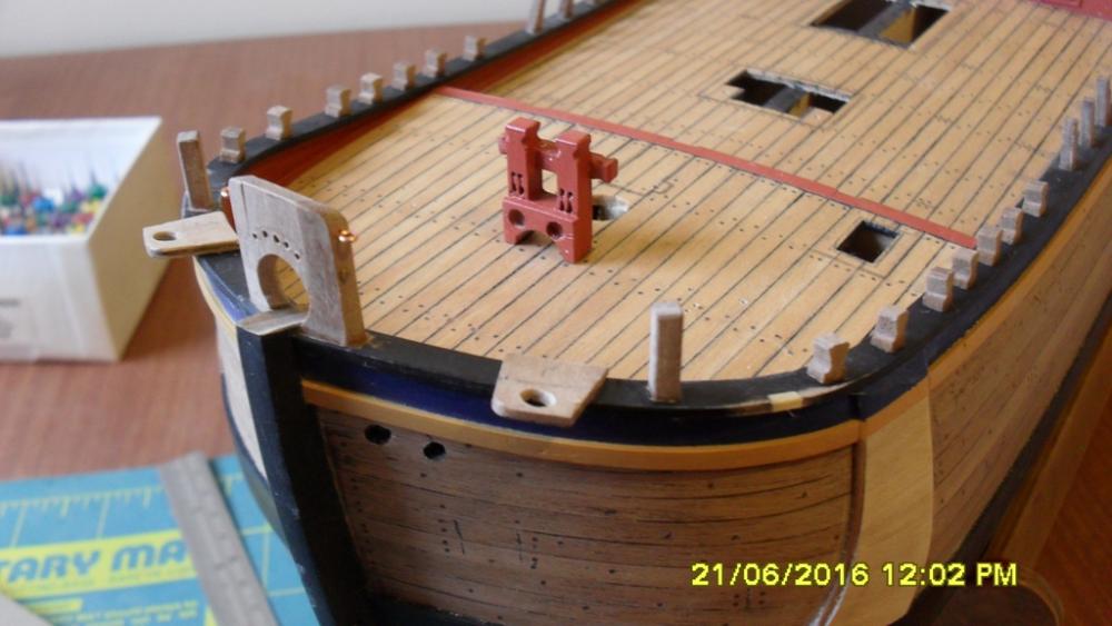
Roughtree rails and swivel gun posts. Pre drilled eyebolt holes in the deck before fitting the roughtree rails and pre drilled swivel gun mounting holes in posts before fitting. Glued a length of 1x4mm walnut on the top of the main deck rail to give it the extra thickness and overlap onto the quarterdeck bulwark capping as indicated in the draughts. Cheers Dashi


-
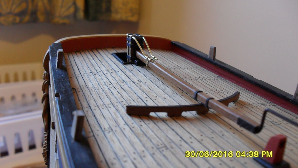
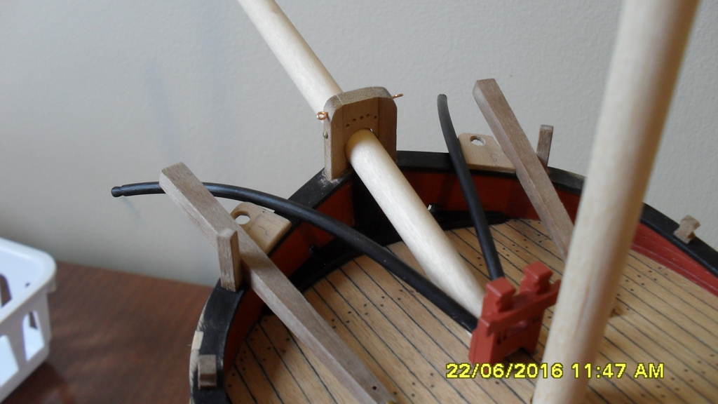
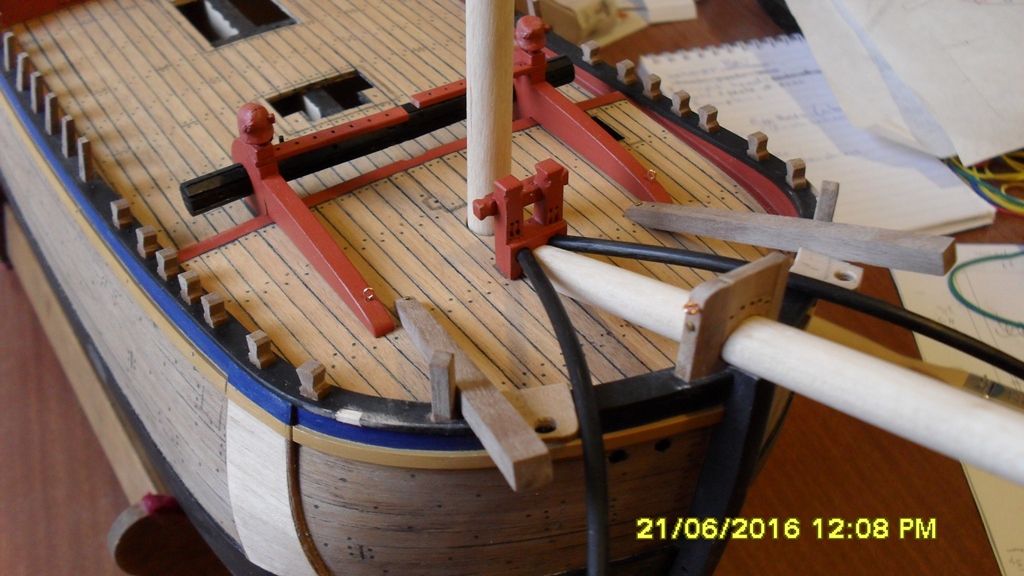
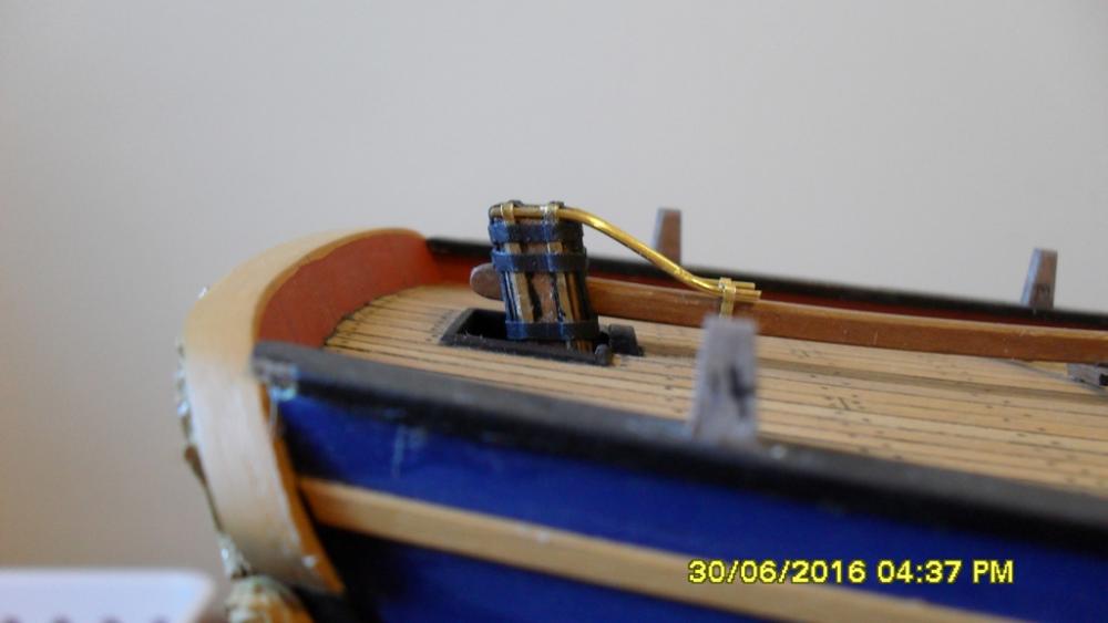
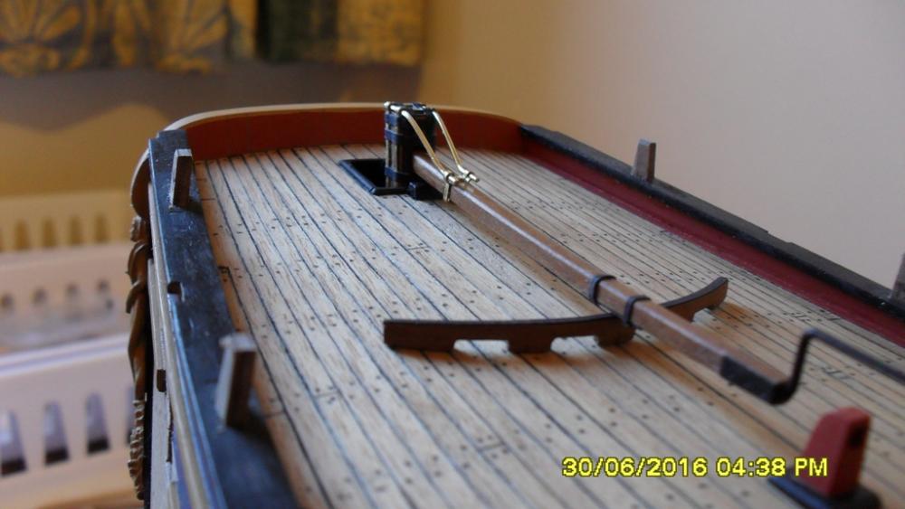
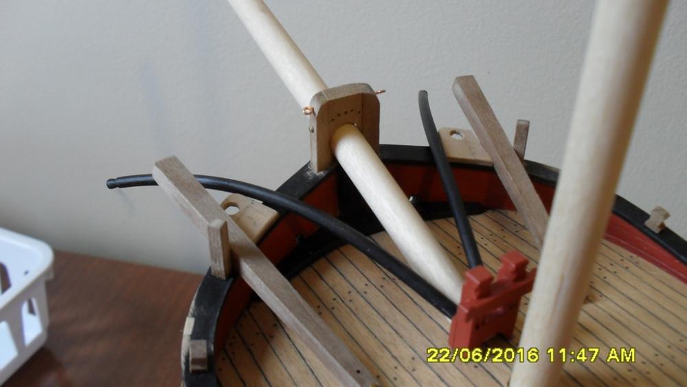
Thanks Pat and Dave and all the likes. From here I started researching the positions of eyebolts on the deck and especially those running next to the bulwarks before I fit the rough tree rails which will be in the way if I don't do this now. By bashing the stanchion positions to match NMM draught ZAZ7844 I've deviated from the kit and AOS which has thrown up a bit of a research challenge for me. One thing I'll mention now is that I've noticed a timberhead lurking behind the forward quarterdeck stanchion which looks like it might be there for belaying the forecourse sheet to. To clear the carriage guns and give the 5-6' room needed to allow enough hands to belay the forecourse sheet I might lead the sheet through the chess tree (Ship Model Builder's Assistant p.153) below the main tack fairlead and then up and rove through a block on the second forward quarter deck stanchion then forward belaying to the timberhead. This would be instead of the sheaves shown in AOTS and NMM draught ZAZ6587. But more on that later after more research and I've finalized and drilled those eye bolt holes in the deck. I wanted to have a go at making my idea of the tiller braces so re-made the rudder head straps using brass and card to facilitate this. It appears that initially Cook had ordered the Armourers to 'repair the tiller braces' when they set up the forge at Queen Charlotte's Sound New Zealand. I assume this last repair didn't work, so then he ordered the wooden tiller support to be made to replace them. I won't include the tiller braces in the final fit. I've also included an iron rail on the wooden tiller support and skid under the tiller made from card because I believe these would be needed. Cheers Dashi


-
I like your rigging setup and I'm impressed with the detail you have put into those carriage guns at 1:60 scale. Cheers Dashi
-
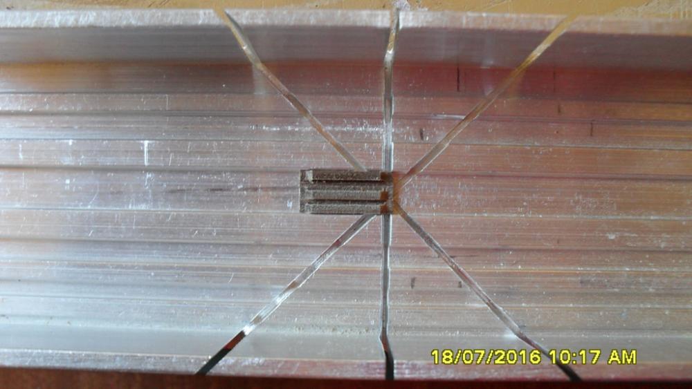
Knight heads: A closer inspection this morning revealed that the shipyard had erred too much on the side of caution not wanting to make them too short and had inturn made them too tall as Steve had rightly spotted. After a series of careful sandings and measurement checks I think they should now be within a gnat's whisker of the right height, that's assuming I've got my measurements correct. Cheers Dashi
-
Thanks for the likes. Thanks Pat :-) Cheers Steve and I think you might be right about the hight of the knight heads. From the draught I've measured their hight to around 1'6" or the diameter of the bowsprit from the top side of the bowsprit which could be wrong, so I'll take a closer look tomorrow. Thanks for pointing this out and could I ask you to double check my measurements for me please as I don't want to sand too much off? Cheers Dashi
-
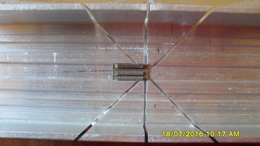
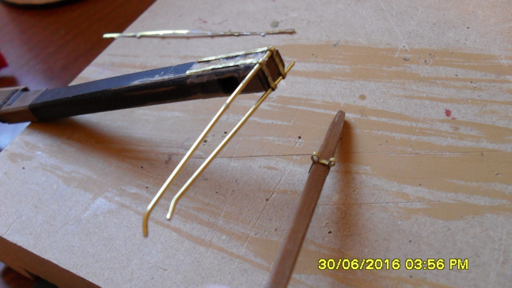
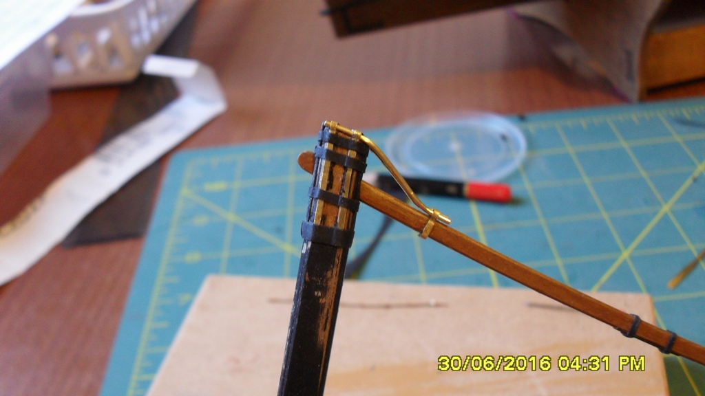
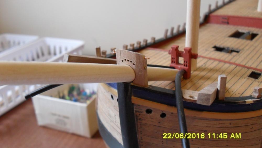
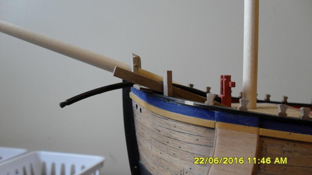
Update: Stanchions, bits, seats of easement and knight heads bashed and fitted according to the shipyards interpretation of the draughts and allowing for a shorter waist. The stem: To work out their positions I first fitted the fore tack bits for the cat heads to sit against. Then with cat heads dry fitted in position to the plan, I bashed the seats of easement to the 1771 draft and glued in place. Taking another look at Sydney Parkinson's sketch I now could just make out what I think might the boomkins running over the false rail up against the seats because of a difference in height of the false rail. Tack Boomkins or bumpkins: After several failed attempts at seating them under the bowsprit as the kit plans and AOTS have I gave up and tried a different 'tack'. Influenced by HMS Victory I decided to try them stepped in the fore topsail sheet bits. Taking another look at the as fitted 1768 and 1771 draughts I noticed attached to the fore part of the sheet bits an extra thickness which gave the wood needed to step or seat their heals here. Also I was having trouble using the square bumpkins provided in the kit so made some replacements out of bamboo skewers. With them in this new position I took a Sydney Parkinson shot. Don't know if I've got it right but am happy with that. Knight heads: I took one look at the kit ones and put them aside to bash replacements. The top block is dry fitted and held in place by pins and eye bolts and drilled with fairlead holes so I don't think I'll need the fairlead saddle which then will allow the jib boom to run in further if that makes sense. Cheers Dashi


-
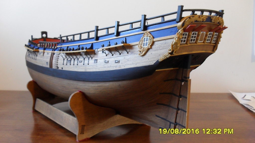
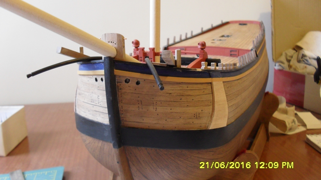
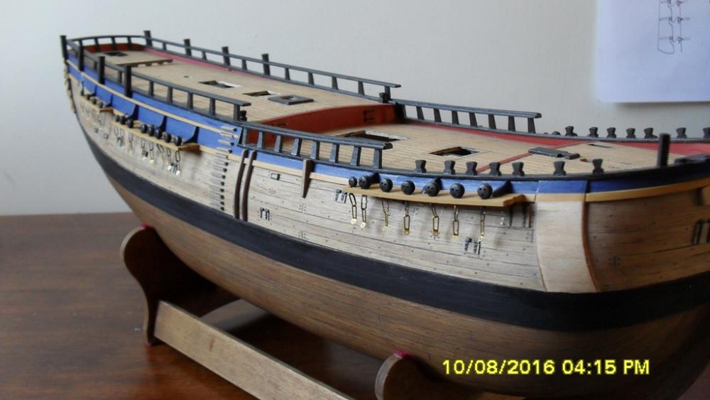
Thanks Pat and everyone for the likes and interest. I'm looking at this photo and wondering if I should have painted the great cabin window frames white now that I've removed the blue paint?
-
I just want to say thank you Pat in post #122 for accurately understanding and explaining my position better than I am capable of, and for your well thought answer to my initial question. Also I'd like to thank everyone who contributed their time and input or who has taken an interest in my question. This topic has raised some good points and other questions, such as why the tiller was so long. Unfortunately I don't have the energy or the health to pursue these questions any further in this discussion. My presence is now required in the shipyard and else where so thanks again everyone. Cheers Dashi
-
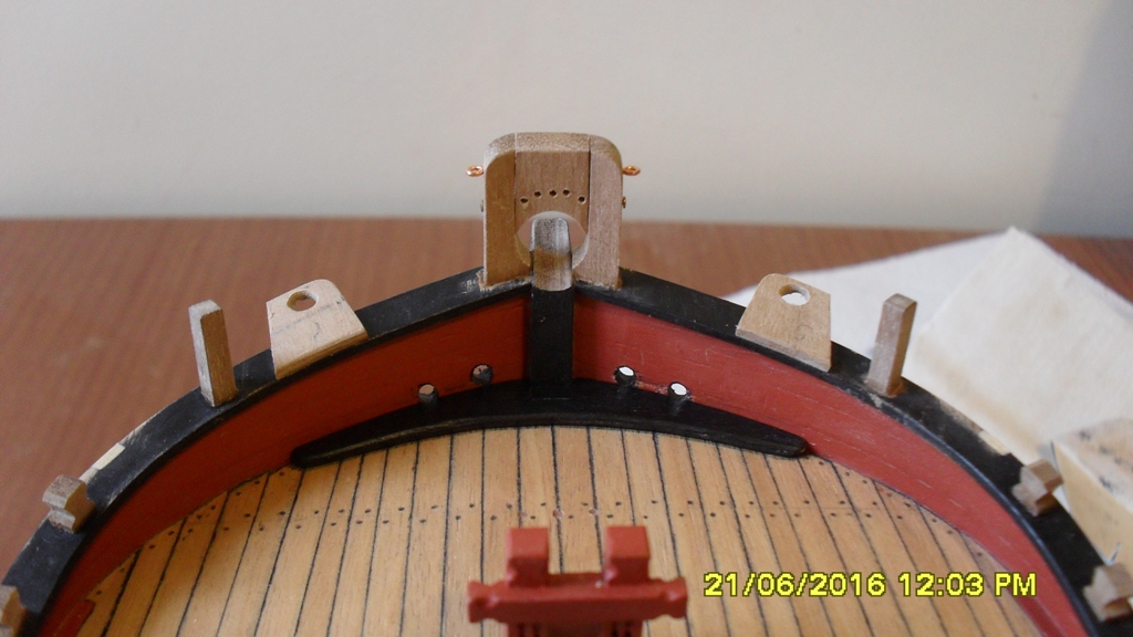
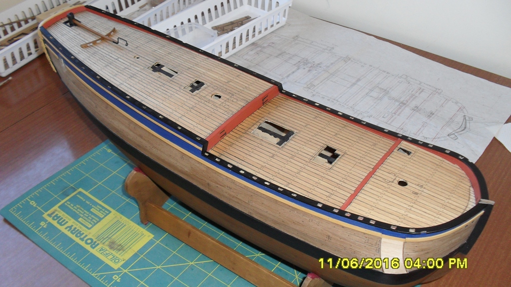
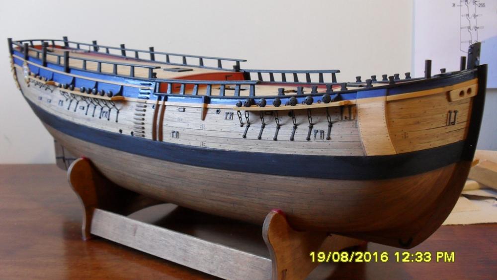
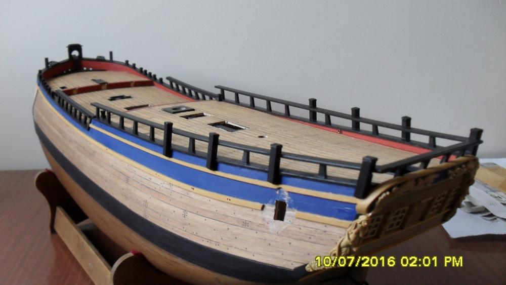
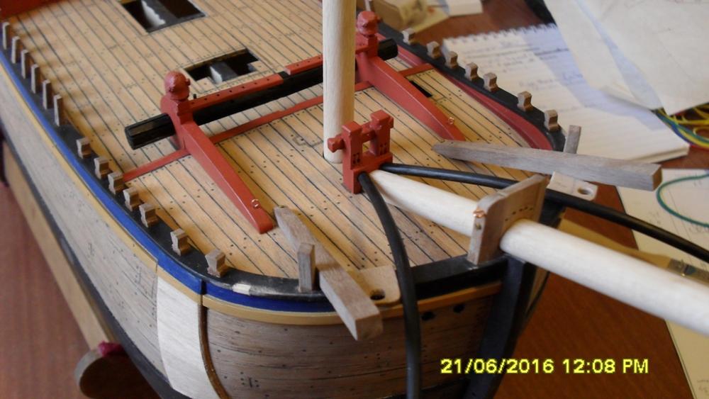
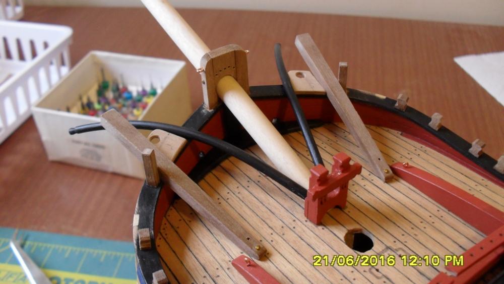
Thanks Dave. Your build is looking good too. Update: Plugged old stanchion holes and dremeled new ones to match 1768 as fitted draught. After fitting the fore rails the yard boss noticed some of the holes were in the wrong places so remeasured and very carefully re filled and dremeled. Stripped back the supposed 'tiller support' to bring it to what I think might be more acceptable for Cooks New Zealand 1770 jury rig. Not sure if the armourers could have forged an iron runner so at this stage have left it off. I'm also not sure whether the tiller braces that it replaced would have been kept on or removed. Logic tells me they would have been taken off as they might interfere with the sweep and cause the tiller to jamb. I'm still thinking on that. One thing I'm reasonably sure of is that Cook wouldn't have sailed until he was certain it would last the rest of the voyage through uncharted waters. Painted rails and dry fitted everything to see how it looks. Cheers Dashi


-
Jud I don't how relevant this is as it's not a contemporary source, but I recall learning about cordage diameter to bend ratios when I was in the corps. So I've searched and found this in the 'Rope User's Manual', page 38. http://www.samsonrope.com/Documents/Rope_Users_Manual_WEB.pdf. It's not specifically talking about ship hawse, but suggests a minimum bend ratio of 1:3 for bitts fairleads and chocks. Dashi
-
Hi Dave, I was wondering about doing a rudder coat myself but thought it to difficult so you have now inspired me to reconsider. So a very neat job there Dave including those scuppers. Cheers
-
Thanks for the likes and thanks Ron. I think Pat has offered a really good interpretation of this log entry to my question in the discussion I started on this and which could alter my representation of that tiller transom as Cook calls it. Certainly worth dropping in to check it out http://modelshipworld.com/index.php/topic/13109-hmb-endeavour-tiller-and-steering-question/. Cheers Dashi