HOLIDAY DONATION DRIVE - SUPPORT MSW - DO YOUR PART TO KEEP THIS GREAT FORUM GOING! (Only 13 donations so far - C'mon guys!)
×


dashi
-
Posts
248 -
Joined
-
Last visited
Content Type
Profiles
Forums
Gallery
Events
Everything posted by dashi
-
 Thanks Jud. I was starting to wonder what was going on also? The Encyclopaedia Britannica page does mention such a thing as a Tiller Transom in reference to shipbuilding when the tiller exited the stern in earlier ships which I think Jud is pointing out also. I wonder if it is possible that it is this earlier terminology Cook was drawing on to describe this transverse support timber that he got the carpenters to fix as a tiller support in place of those iron braces? I see the annotation as an attempt to clear up possible misconceptions that may have arisen here because of Cooks use of this term. Therefore I don't think we should dismiss this annotation which indicates that Cook is referring to the carpenters as fixing a transverse timber under the end of the tiller as a support. Pat's answer seems to stack up the to the evidence and as I've already stated my representation could be wrong in light of this.
 -
As indicated in those definitions it is important to include an adjective to describe which transom is being referred to otherwise the context is lost. In this context I think Cook is referring to a Transom associated with the support of the Tiller. Not a deck or Stern Transom etc. Thanks
-
Welcome aboard. Cook is talking about the Tiller being in danger of breaking, so it is in this context that I think his use of the word 'Transom' is taken to mean a 'Transverse Supporting Timber'. I don't think he is talking about the rudder or rudder head. http://www.oxforddictionaries.com/definition/english/tiller looking at the tiller length and weight, and to compare apples with apples so to speak, then I think there are examples of tiller supporting quadrants where the length and weight of the tiller require support. The Arming and Fitting of English Ships of War 1600-1815 by Brian Lavery, Chapter 2 Tiller and Whipstaff and Chapter 3 The Steering Wheel. Looking at the Bounty it's tiller appears considerably shorter compared to Endeavour which does highlight that Endeavour appears to have an exceptionally long tiller for the size of vessel and therefore as the physics suggest would have required support possibly by use of a sweep, which have been in use for supporting larger tillers since at least the use of the wipstaff in the 17th century. Where the tiller is below deck then the sweep is fixed to the overhead beams and the tiller hangs from it via what some call a gooseneck. However the term gooseneck is also used for the iron fitting attached to the end of tillers that fitted into the whipstaff. Lavery gives a description and drawing of the use of a sweep above decks in smaller vessels, ( 1771 draught of Endeavour), where the tiller requires supporting. (page 23) The Arming and Fitting of English Ships of War 1600-1815 by Brian Lavery, Chapter 2 Tiller and Whipstaff and Chapter 3 The Steering Wheel. Hope this helps answer some of your questions. Cheers Dashi
-
Pat the more thought I give your interpretation, the more sense it makes. It does seem to hold up quite well with the evidence we have on hand including my very unqualified attempt at figuring the physics. I am still requesting if an engineer, fitter or at least a qualified person from the building trade could check and complete my math in an earlier post to help approximate the size and position of those iron Tiller braces that kept breaking? I have asked fitters about the physics and they all agreed that the physics of that tiller required it to be supported by some means and the best method is that tiller sweep or Transom I think Cook is referring too. I'd imagine those braces would have been working at the limit of their strength with too little tolerance which would explain Cooks apparent frustration with them as being supplied to do a job they weren't up to.
-
The defininition of transom dosn't just refer to the aft timbers of a ship or boat, but any transverse supporting timber http://www.merriam-webster.com/dictionary/transom . I have only referenced one source which agrees with all other sources I have cross referenced for this log entry. So here is another source http://gutenberg.net.au/ebooks/e00043.html#ch6 In this context I think Cook is refering to the tiller and not the stern or stern post as opposed to the transoms you are referring. But I need more evidence. A broken stern transom would be a major structural failure resulting in extensive repair work. Granted they were anchored a while with their forge set up on shore for repairs. The note which appears in other sources of the log entry is refering to the end of the tiller. What about the physics? Thanks Frankie for sharing your point of view.
-
Thanks Jud, and Pat. I re read it and Pat your interpretation is a possibility I need to consider and how it might change the construction of the tiller transom and how those iron tiller braces fit into the picture. If I've understood you, then this interpretation suggests the job of those iron tiller braces was to take the weight of the tiller and that Cook was not happy with them for possibly the same reasons Jud and I have worked out here. So if this is the case then Im not sure if he is referring to repairing the iron gudgeon braces as has been previously suggested? Cheers
-
From the entry for Saturday 27th January from the book, 'First Voyage Around the World: Captain Cook's Journal During his First Voyage, Page 272, Cook writes: "Saturday, 27th. Fresh gales, Westerly. This day we got the Tiller properly secured, which hath been the Employment of the Armourers and part of the Carpenters since we Anchor'd at this place; the former in repairing and making new Iron work, and the Latter in fixing a Transom,* for the want of which the Tiller has often been in danger of being broke; the Iron braces that supply'd the want of a Transom have broke every time they have been repair'd." *The reference at the bottom of page 272 is indicating in this context Cook is saying: * A transom is a curved piece of wood which supports the end of the tiller. Note: As has been pointed out later in this discussion this is not the generally accepted use of the word 'transom', which leaves this entry open to interpretation. It is my understanding that in earlier vessels such as carracks where the tiller passed out a hole in the stern, that the transom which passed under the tiller was reffered to as a tiller transom.https://books.google.co.nz/books?id=QU40AQAAMAAJ&pg=PA244&lpg=PA244&dq=tiller+transom+definition&source=bl&ots=qs6UGheA-I&sig=u-x5Oq0-HxISibbwwICUKXlkS18&hl=en&sa=X&ved=0ahUKEwirnaKZz6DNAhWHspQKHTNTAZUQ6AEIJzAG#v=onepage&q=tiller%20transom%20definition&f=false My opinion based on the evidence to hand is that in this context the anotation is using the term 'transom' to mean a transverse timber support which passes under the tiller to support it's weight along it's sweep to replace the job of the iron tiller braces that kept breaking. But not having the carpenters log then this is just my best guess and we may never know for sure. I hope we can agree that Cook wouldn't have sailed with out ensuring the 'fix' to the tiller support 'defect' that took place over 12 days in Queen Charlotte's Sound New Zealand among other running maintenance repairs and de-fouling was up to the job and going to last the long voyage through uncharted waters that was still ahead. https://books.google.co.nz/books?id=WT4zDAAAQBAJ&lpg=PA272&dq=endeavour%20tiller%20transom&pg=PA272#v=onepage&q=endeavour%20tiller%20transom&f=false Cheers
-
Thanks for the likes and very kind comments. Sorry I didn't find it sooner Pat. While researching information regarding the Woolwich Yard Navy refit of Endeavour into a navy transport, which I still haven't found I stumbled across a very interesting brief of Cook's log regarding the repair and replacement of the wooden tiller transom which I hadn't seen before. Following this trail took me to page 272 in 'First Voyage Around the World: Captain Cooks Journal During his First Voyage' . https://books.google.co.nz/books?id=WT4zDAAAQBAJ&pg=PA272&lpg=PA272&dq=endeavour+tiller+transom&source=bl&ots=OmVlEi3R_k&sig=1CYoj3AIkymFXQddNKV3njef8h0&hl=en&sa=X#v=onepage&q=endeavour%20tiller%20transom&f=false From the entry for Saturday 27th January from the book, Cook writes: "Saturday, 27th. Fresh gales, Westerly. This day we got the Tiller properly secured, which hath been the Employment of the Armourers and part of the Carpenters since we Anchor'd at this place; the former in repairing and making new Iron work, and the Latter in fixing a Transom,* for the want of which the Tiller has often been in danger of being broke; the Iron braces that supply'd the want of a Transom have broke every time they have been repair'd." *The reference at the bottom of page 272 states: * A transom is a curved piece of wood which supports the end of the tiller. Here is my interpretation from previous posts and a discussion http://modelshipworld.com/index.php/topic/13109-hmb-endeavour-tiller-and-steering-question/ of that 'curved piece of wood which supports the end of the tiller', which Cook is reffering to as a 'transom' in this context and which is drawn on draught zaz6494 of Endeavour 1771 Woolwich Yard http://collections.r...ects/86385.html .
-
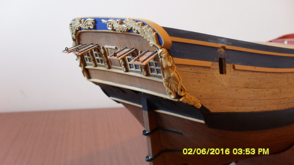
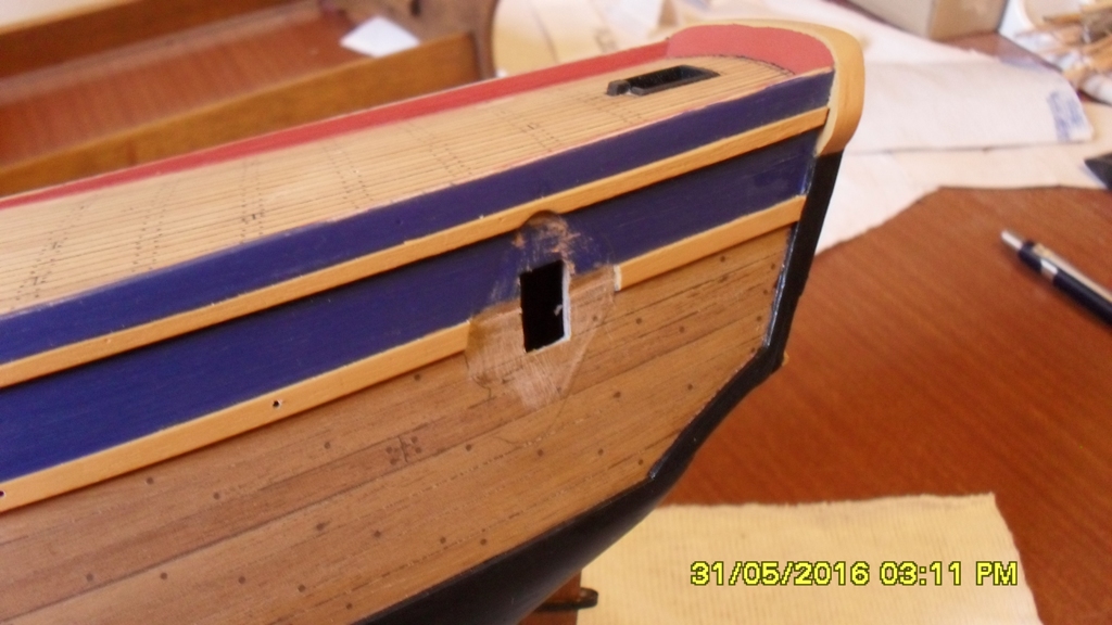
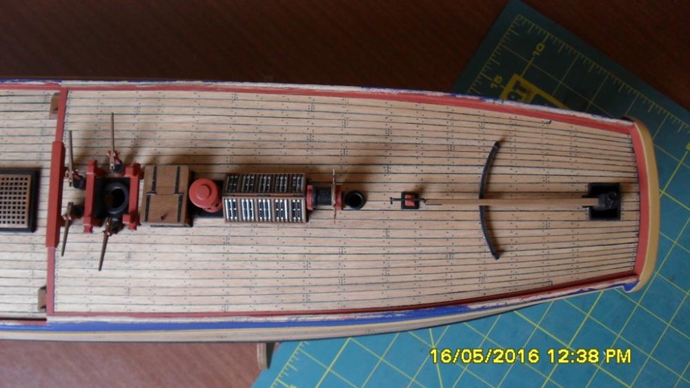
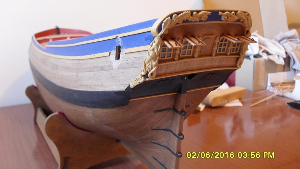
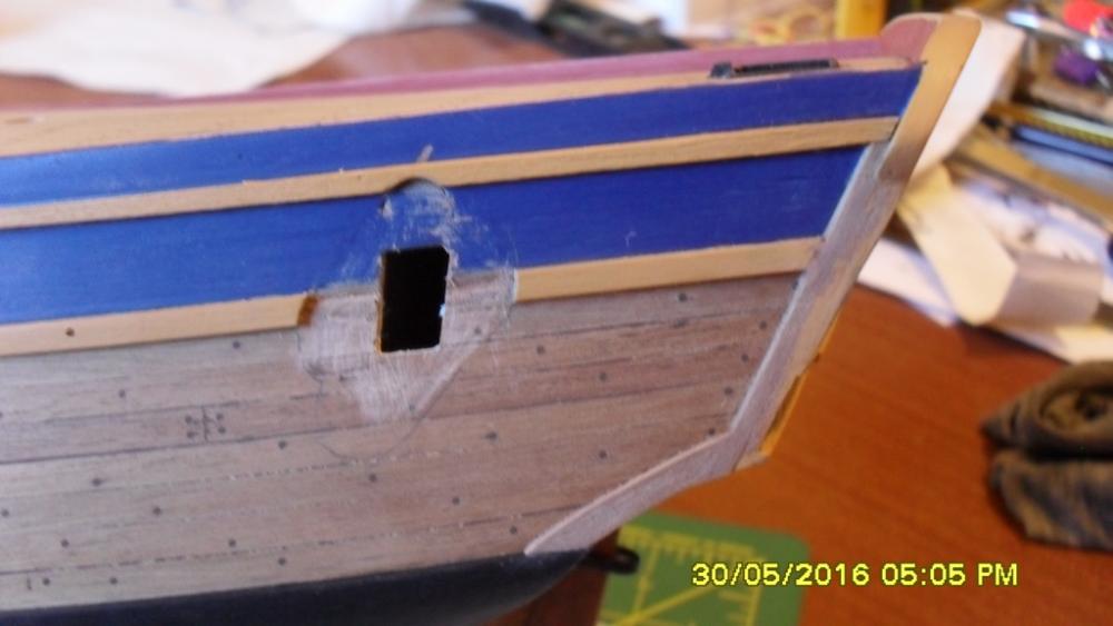
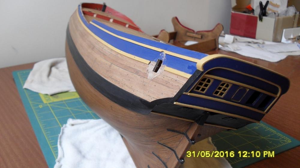
Stern facia: Thought it would be easier to do the facia with the hull upside down so decided I needed to get this done before those bulwark cappings. I'm putting them off for as long as possible to give my brain a chance to work out the best approach for the retro-fit which I think I might now have. Although a friend and I really liked the all blue facia, I must confess to a moment of dread after I first painted it all blue. Plus I'd glued the upper window ledge along the wrong side of my pencil marks making it too tight for the lids, so after seeing that water colour by Sydney Parkinson with the blue taffrail with what looks to be natural beneath and going by the only draught of the stern I have found which does not have the upper window ledge I decided a slight retro-makeover was needed. Holding my breath I dived in and after a couple of days had removed the upper ledge and sanded off the paint. I then applied my pigmented stain and am happy with the result. One rooky mistake I made was to fit the windows before drilling the holes for the window lid hinges because some of the fine sawdust stuck itself to the inside of the glass, not that it's too noticeable.The window lids were also stained with the same pigmented stain and are dry fitted so can be put aside until much later.

-
Cheers Dave and thanks everyone for the likes. It is everyones good works that inspire me to give this project my best. That missing woodwork on the stern had been bugging me from the start. In this watercolour from Parkinson if I zoom in I can just make out the blue on the taff rail. http://acms.sl.nsw.gov.au/album/ItemViewer.aspx?itemid=897249&suppress=N&imgindex=26
-
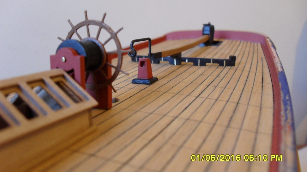
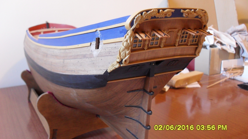
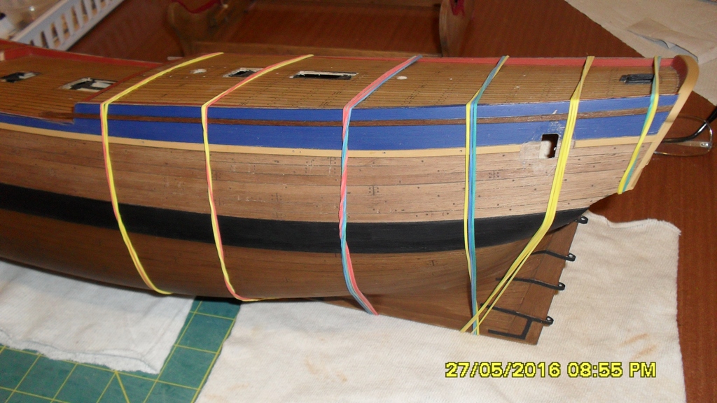
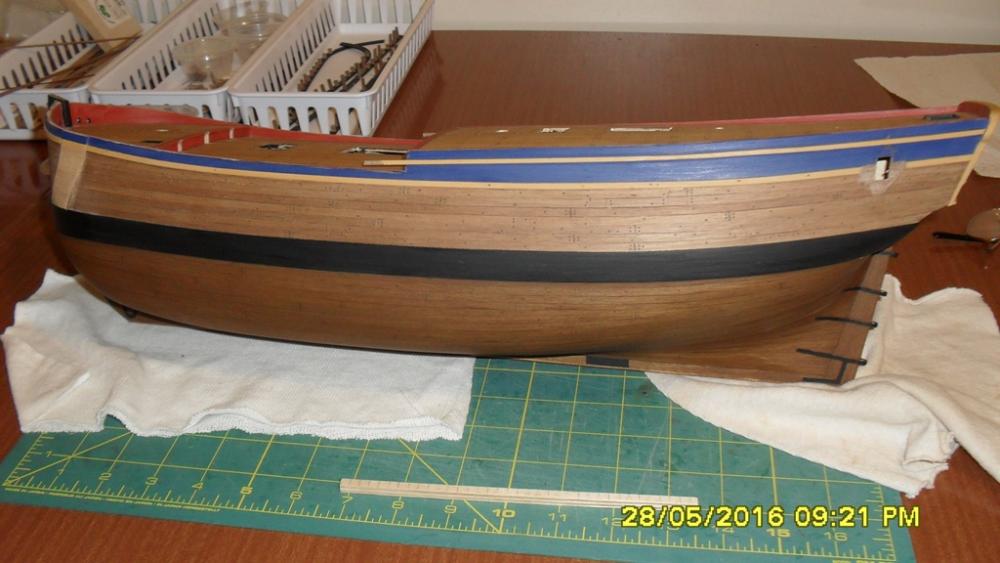
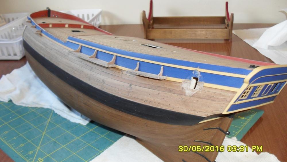
Update: Thanks for looking in on my build and the likes. The beading I'm adding according to Sydney Parkinson's sketch has been pre-painted and glued after scraping the paint away along the hull in the area for it so the white glue will hold. I then had to trim the main channel brackets and remove a small curve for the quarter badge for these to fit under it. Then standing back I reassessed the stern timber work and decided I needed to bash that into line as much as I could from the as fitted 1768 draught and the stern view by Sydney Parkinson. Doing this was a little fiddly but on this build I've learnt that a little filler and paint can cover a multitude of sins once I've got the timber work as good as I can get it. I haven't quite got the stern side vertical edge quite parallel because I'd previously shaped to fit the figurine which hides this. I also had to fill out the forward outer side of the taff rail with some 1x4mm walnut so the taff rail is the same thickenss. Another reason for refitting the stern timbers is the kit has the lower counter decoration under the counter where as Parkinson's sketch clearly shows it around on the hull as does the replica which is where I will be fitting it. Next is the bulwark capping which will need a lot of altering to move the rail stanchion positions from their kit positions to the positions drawn on the 1768 proposed refit NMM zaz6588 and the 'as fitted' draught NMM zaz7844. It looks like the rail stanchions replace the timber heads as belay points where there is a rail, so will need to be well attached.

-
She is looking really impressive Steve.
-
Mast Lengths and their above deck heights for HMB Endeavour
dashi replied to dashi's topic in Masting, rigging and sails
I did consider that Druxey but figured in my head that if the formula to work out the diameter of the main and foremasts was the same, then if you take the ratios of their fulcrums and compare it to a lower deck stepped mizzen then this ratio should be proportional and therefore the falcrum forces will be ok. You can check this if you like. But I'm ok with it for now. By the way Wayne you will be pleased to know I found that last painting you posted and its by Samuel Atkins 1794. It appears to be evidence for the taller mizzen because although it is late if you rule a horizontal line parallel to the water line of the bark from the fore top (not the top masts or gallant) it should cross below the main top 3 to 5 feet and then where it crosses the mizzen the top should be around 8 feet below the line. Which looks to be the same as in Parkinsons sketch with the mizzen at the taller height putting the mizzen top around 8-9 feet below the main top. If it were the shorter mizzen mast stepped in the hold then the mizzen top would be 18 feet below the main top which it isn't. So interesting thanks. Anyways I've taken a step back from this discussion as I have an answer I can live with for now. It might not be the answer others want but they are equally free to draw their own answers from the validated evidence presented here. Thanks again everyone.- 63 replies
-
- 2
-

-
- HMB Endeavour mast lengths
- above deck mast heights
- (and 3 more)
-
Mast Lengths and their above deck heights for HMB Endeavour
dashi replied to dashi's topic in Masting, rigging and sails
First I think before dismissing this out of hand we to need review draught zaz6591 of the cabin or orlop deck which you provided and which omits the hole for the mizzen standing mast as I think it raises some interesting questions that need answering. To do this and in the interests of clarity I will attempt to list some of the main points that have been raised in this discussion and possible relationships between them. Point 1 : Draught zaz6691 raises the question that the mizzen was stepped in the orlop deck if Waynes 'no hole' argument is true. Point 2: Wayne you made the argument that you didn't think the shipwrights would have made mistakes. I'd like to agree with this but the evidence you have provided in draught zaz6691 might not support this argument. Point 3: Draught zaz6594 of the 1771 deck plan provide by Wayne along with other deck draughts disagree with draught zaz6691 and show holes through all the decks for the mizzen. Point 4: Point 3 supports the argument that the missing mizzen hole in draught zaz6691 is in fact very likely a draughting error. If there is no other supporting evidence for the theory of the deck holes or lack of them for determining mast steps on plans then this argument needs to be discounted. Point 5: Point 4 negates points 1 and 2. Point 6: The last painting Wayne provided has no reference date or who it is by or what ship it is and so can't be verified as evidence for this discussion. Point 7: Parkinsons sketchs clearly show a taller mizzen inline with contemporary ship building measurements wayne has provided and the shrouds all appear very close at the same angle from their respective channels. Point 8: Steves AL model because of the lower mizzen and the replica Endeavour also because of the lower mizzen have the mizzen shrouds at a lower angle compared to the fore and main shrouds. Point 9: Point 7 negates point 8. Point 10:Wayne in your last post your provided evidence with a link in which it clearly gives two formula for working out the length of the mizzen. If the mizzen is to be stepped on deck then it is to be 2/3 the length of the main mast and if it is to be stepped in the hold then 3/4 the length of the main mast. Point 11: The formula in point 10 is further supporting evidence for the practice of both deck stepped mizzens from at least 1761. Which deck they are referring to it doesn't say. It is proof that other formula were used which isn't in dispute. Working backward none of these formulas appear to support the Woolwich Yard measurements with the exception of a formula in Steel's compilation which is not listed here and came 30 years later. Point 12: Druxey worked out the mizzen height from it's diameter which came to 60' which matches one of steel's formula. Referencing points10 and 11 suggests that this is the length if it were stepped in the hold and makes it 10' taller than the Woolwich Yard measurement of 50',5" which it would be if stepped in the lower deck. It would need to keep the diameter proportional to the longer mast of 60' because the stresses from the quarterdeck partners would still be the same regardless of whether hold or lower deck stepped. In conclusion: I feel like we have exhausted all the evidence there is. After careful consideration the theory of a deck stepped mizzen is supported and does explain the Woolwich yard measurements using a formula from Steel's compilation of 30 years later as I originally posited. This is not conclusive but it is valid. Secondly the question of the foremast length: After further research I think the Woolwich yard measurements are ok here, but that it is still possible that there has been an error. As far as I'm concerned this discussion has answered my questions, I really appreciate the efforts of everyone who took the time to provide valid evidence and their respective points of view. Nothing is conclusive and we are each entitled to our own conclusions and points of view so with that in mind I'd like to thank everyone as I have learned a lot that I can now use on my build of the HMB Endeavour.- 63 replies
-
- 2
-
-
- HMB Endeavour mast lengths
- above deck mast heights
- (and 3 more)
-
Mast Lengths and their above deck heights for HMB Endeavour
dashi replied to dashi's topic in Masting, rigging and sails
Here is a link to an engraving by William Byrne believed to be done from a lost drawing by Sydney Parkinson of Endeavour being repaired. http://collections.rmg.co.uk/collections/objects/269382.html If you look closely you will notice two interesting facts. First the angle of the shrouds are identical and second the ratio of differences in height of the standing masts. The mizzen standing mast does not appear to be anywhere near 18 feet shorter than the main standing mast and the fore standing mast height appears to be some where between the main and the mizzen. Comparing the shrouds, they all appear to be at the same angle which the mizzen standing mast shrouds couldn't be if it were 18 feet shorter than the main standing mast. And here is another Parkinson sketch showing the shrouds all at the same angle. https://www.google.co.nz/search?q=sydney+parkinson+endeavour&client=tablet-android-samsung&prmd=inmv&source=lnms&tbm=isch&sa=X&ved=0ahUKEwjinfvcnvvMAhWEW5QKHQ2FA6sQ_AUIBygB&biw=1280&bih=800#imgrc=2Kjd5xBOBhUSFM%3A -
Mast Lengths and their above deck heights for HMB Endeavour
dashi replied to dashi's topic in Masting, rigging and sails
Thanks Wayne. Thats an interesting draught from NMM id ZAZ6591 you put up of what looks to be the orlop deck and while I can see the hole for the main mast forward of the quaterdeck hatch passing through it I can't see the hole for the mizzen? Your arguement seems to be at odds with this draught, are you saying that the mizzen is stepped in this deck because there isn't a hole for it? As to the deck beams as far as I am aware it was the quarter deck that was significantly altered and not the lower deck but I could be wrong so I'm not clear on what you are trying to say here regarding the quaterdeck beams and I am aware of the broken red lines on the proposed refit of 1768. As far as deck beams are concerned they are placed where they need to be and not necessarily placed hard up against a mast if you look at the hole for the main mast in the draught you have provided. You make a good point about the accuracy of the Woolwich yard measurements which I wan't to agree with and am trying to prove here because one of the arguments around the mizzen is that Woolwich made a mistake with the slip of a pen which like you say I also find hard to believe. Parkinson's drawings clearly show the Endeavour with the taller standing mizzen and these were drawn first hand. It is his drawings and the woolwich yard measurements that suggest to me the mizzen was stepped in the lower deck and not the keelson. Here is a link to Parkinsons drawing. https://www.google.co.nz/search?q=parkinson+endeavour&client=tablet-android-samsung&prmd=inv&source=lnms&tbm=isch&sa=X&ved=0ahUKEwj9qMWV-_rMAhWGn5QKHfIGBVIQ_AUIBygB&biw=1280&bih=800#imgrc=hClazxzzPQr-HM%3A As far as the foremast is concerned I have been rechecking everything and using the Woolwich measurements there is about a 2.5' drop in height from the main to the fore standing masts contrary to what I first thought which might be ok. But this is what I'm asking for help with to check these heights. With the mizzen stepped in the lower deck there is a drop in height of around 8' from the main standing mast to the mizzen standing mast and 5.5' from the fore standing mast to the mizzen standing mast. But if you were to step the 50' mizzen in the keel then this would change to an 18' drop from the main to the mizzen which dosn't agree with any of the figures in any of the charts that you have provided and nor does it agree with Parkinson's drawings. -
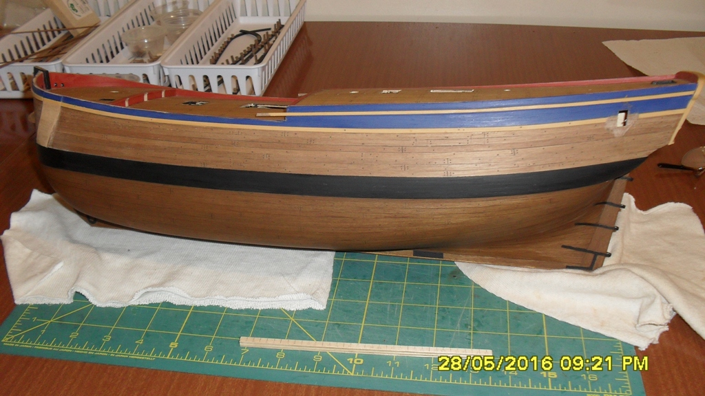
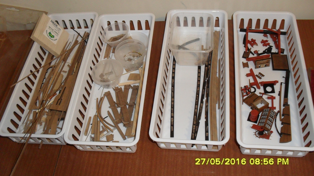
Thanks Dave. Yeah I think I got one of the first kits out of the yard going by it's serial number. Going by the comments of Paul who recently completed his build it sounds like they have improved the quality and quantity of the wood. I know I moan about the kit sometimes but I'm really enjoying this build and learning so much as it is challenging me on many levels. I'm giving it my best and it's giving it's best back, so yes at the end of the day I think I'm getting my money's worth. A minor update: After Steve drew my attention to the Parkinson drawing and its connection with the as fitted draught I started to really appreciate the historical value of those sketches. So while I ponder what to do with the rail stanchions I thought I'd start my next kit mod using based on those sketches, the adding of the beading which runs 1' beneath the quarterdeck bulwark capping rail and which the swivel gun posts sit above. The only thing I could do was split a 1x4mm walnut plank to give me the 1x2mm beading. Easier said than done and after 3 breakages I finally got a set which I've soaked and shaping on the hull in position. I used a drawing compass set at 1' according to my scale rule to get the line. Tomorrow I will pre paint them, then glue if I have time. These needed to go on before the bulwark capping so now is the time to do it. And here are the trays containing parts in various stages of completion along with a materials tray.


-
Wow that is looking neat Dave.
-
Cheers Steve. Yes and looking at the AOTS book there is a minor mistake in the Woolwich foremast measurements which according to the original draught of 1771 is 21 yards and 28 inches as opposed to 21 yards and 26 inches. I wonder if this mistake also occurs on the silk compilation? As you point out and what I find really misleading also is the AOTS book under sources on page 23. The description for draught 3814c (the later silk compilation) overlooks the fact that it contains the 1771 Woolwich Yard measurements. Here the AOTS book obviously confuses the title of the copied draught of 3814a for the title of the compilation and even then as we have discovered 3814a is not marked 'as fitted'. Unless I'm mistaken and like you indicate, this leaves only draught 3814 as the original 'HMB Endeavour as fitted in 1768'. Along with Parkinson's drawings on pages 32 and 33 of the AOTS which agree with it as you have pointed out along with a taller mizzen which the AOTS does point out to it's credit. I don't understand why the AOTS didn't pay more attention to Parkinson because they did have the draughts we have access to today as listed under sources page 23? That's the way of research I guess as it comes under scrutiny through the process of review. Re the deck fittings. I'm pegging and dry fitting as much as I can and won't glue anything until the last possible moment. Each stage goes into it's own small tray until it's ready for a final glue and fit, so things don't get mixed up or lost or broken. And yes the quarter badge is kit supplied and to their credit some of the things in the kit are actually quite good with some exception of some poor quality wood, draughting and scale anomalies. There is a huge knot in the middle of my mainmast so I can't use it and it will have to be replaced.
-
Mast Lengths and their above deck heights for HMB Endeavour
dashi replied to dashi's topic in Masting, rigging and sails
Thanks Wayne. Yes I agree that if the mizzen were stepped in the lower deck as opposed to the being keel sepped then you would need a heavy vertical stanchion and other timberwork to support it with out a doubt as you and Druxy have pointed out. I will try to expand my previous answer based on all my experience using technical drawings and draughts from the building industry and in heavy industrial construction and maintenance, plus model ship kits in recent years. In all that time I have never come across all the technical details necessary for building the project to be drawing on one draught. And unless I'm mistaken I can't see any vertical stanchions drawn in below decks on any of the surviving draughts. Therefore I take this to mean that we don't yet have the draught showing this detail if it did exist. Steve provided a detailed analysis of those dashes or asterisk's marking the masts below deck in his post #28 and found that the mizzen dosn't have these marks in the surving original draught of 1768 which is marked 'as fitted'. The silk draught which is also marked as fitted in 1768 has been proven to be a later compilation because not only does it have the 1771 woolwich measurements on it meaning it's title is misleading and is only reffering to the sheer draught which is not a copy of the original 1768 'as fitted' draught. But I've read that draught silk wasn't used until later (I can't recall the source sorry). Along with this evidence and based on the draughts you provided is the Woolwich Yard measurements indicating a shorter mizzen length which has the diameter for a longer mizzen as druxey has worked out. Along with this evidence is the angle of the mizzen chainplates which supports a taller (not longer) mizzen as Steve has confirmed with his drawing. In a previous post I have already provided a link to the Cruiser plans of 1752 which clearly shows a mizzen stepped in the lowerdeck along with it's supporting timbers which exists at Greenwich museum. So unless I'm mistaken all the evidence that we have to date can only tell us that there exists the possibility of the mizzen to be either stepped into the lower deck or the keelson. I hope I've provided a fair answer. Cheers -
Cheers Pat. Steve I'm still puzzling over the stanchion positions. Looking at the rail stanchion positions on the proposed fitted draught 3814b, I can see that the as fitted plan 3814 is a match as you point out and which I'm also trying to follow. The Earl of Pembroke looks to have only iron stanchions originally and the quarter deck and bulwarks have been raised and altered as part of the 1768 refit. Looking at the AOTS book page 46 and it shows the refitted rail stanchions as passing up through the hull from the depth of the orlop deck and doubling as cannon ports on the quarterdeck and waist which in the positions indicated on plan 3814a. And on the deck plan of 1771 it looks like they have drawn these cannon port stanchions in the hull on the quarterdeck and waist which line up exactly with the gunport stanchions on the AOTS plan and draught 3814a on which Steve points out that the original date is smudged and 1768 written over top of it. Hmmmm (puzzled expression) Could it be possible that draught 3814a is the sheer plan that goes with the 1771 deck plan and is part of the Woolwich yard refit. Or maybe the 1771 draught hull and other parts that weren't part of that refit could have been exactly copied from a 1768 draught which is now lost and was part of a set with 3814a draughted in 1768. Either way or another, the evidence suggests to me that these two draughts are uniquely connected via the cannon port stanchions when compared to all the other draughts that I know of except the later silk compilation 3814c. The silk compilation which includes in it's title '1768 as fitted' is interesting because it consists of draught 3814a, along with an exact copy dated and marked as 1771 of the Woolwich spar measurements, and an exact scaled down copy of a draught 3819b marked 'Deptford Yard 11 July 1768 as copy' deck plan which does not have the cannon port stanchions in the hull along with other missing detail. I think the facts speak for themselves because this silk copy having the Woolwich yard spar measurements dated 1771 on it has to date it to being drawn not earlier than 1771 if not much later to when draughting silk was used (according to one source which I can't recall sorry) even though it's title date might lead us to believe otherwise. What all this means I don't know so I will have to sleep on it and hope someone else might have a better idea than me? Along with this there is the position of the timber heads on the bulwark rails to consider and move also should I decide to alter the positions of the rail stanchions. There might not be much of the kit rail left by the time I'm finished with it so I might have to consider a compromise or try and replace the rail altogether which I don't really want to do.
-
Mast Lengths and their above deck heights for HMB Endeavour
dashi replied to dashi's topic in Masting, rigging and sails
Thats a fair point Druxey, but to the best of my knowledge the main and foremast steps aren't drawn either so I don't know if we can use that logic. But yes it is still a fair point thanks.- 63 replies
-
- 1
-
-
- HMB Endeavour mast lengths
- above deck mast heights
- (and 3 more)
-
Mast Lengths and their above deck heights for HMB Endeavour
dashi replied to dashi's topic in Masting, rigging and sails
Thank you Wayne for posting this very clear draught. Yes these are the Woolwich measurements that I am reffering to and the deck plan I am working off of for my build. I'd appreciate it if others could double check my math along the way because I can overlook things and make mistakes. Cheers -
Thanks for the likes and thank you Steve your explaination is really helpful. Yes I hadn't really noticed the positions of those stanchions until I came to move the cannon stanchions. I'm going to have to think about it and decide whether I can live with the stanchions in their current positions or if I can move them. Cheers mate
-
Mast Lengths and their above deck heights for HMB Endeavour
dashi replied to dashi's topic in Masting, rigging and sails
Thank you Steve for your perseverance and great detective work. It's really faint and I can hardly make out a mark for the mizzen. In light of this new information this changes my argument regarding the stepping of the mizzen mast and those asterix's, so with my sincerest apologies to Robin I retract my responses to it. In turn I now thank you Robin for bringing this to our attention for critical review. Post script: Just re read Steves post and missed something important in my haste so need to edit and add this. Please correct me if I've got this wrong, but Steve is there still the question of why it isn't marked for the mizzen to the keelson in the 'as fitted' plan 3814 as you point out? Which if so still leaves some room for doubt as to where the mizzen is stepped. Maybe we will never know or wait and see what information they can recover from the wreck? My question regarding the foremast length still remains open to examination.