dashi
-
Posts
248 -
Joined
-
Last visited
Content Type
Profiles
Forums
Gallery
Events
Everything posted by dashi
-
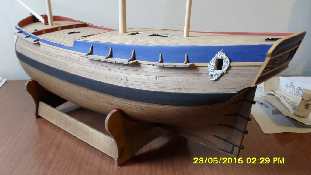
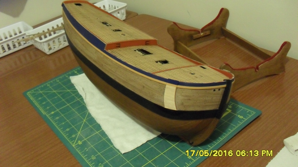
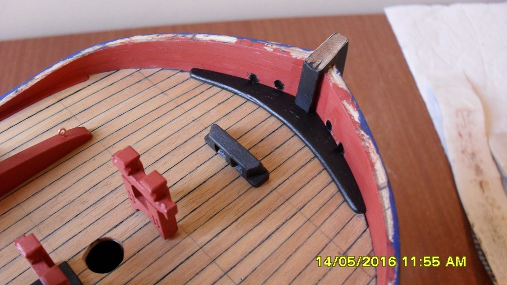
 Just a minor update. The channels are made to the as fitted draught of 1768 with the exception of some finishing and cutting out of the section in the main channel for the light port lid which I can just make out in the draught. I have pinned and dry fitted them plus managed to some how dry fit a quarter badge after cutting out the section of shear plank for it. Going off the draught I measured back from the edge of the stern 7',6" using my scale rule to the quarter badge which moved it aft a little ways compared to the kit plans. Moving the quarterdeck cannon posts to match the same draught on the bulwark capping rail. I have just seen a draught which could explain the origins of the Caldercraft kit and why it is different from the as fitted draught of 1768. It looks to be between the proposed refit draught with the red dots and the as fitted draught Steve and I are following but who knows for sure. So in hindsight with this new information I could quite of easily stayed with the kit cannon post, channel and chainplate arrangement also?
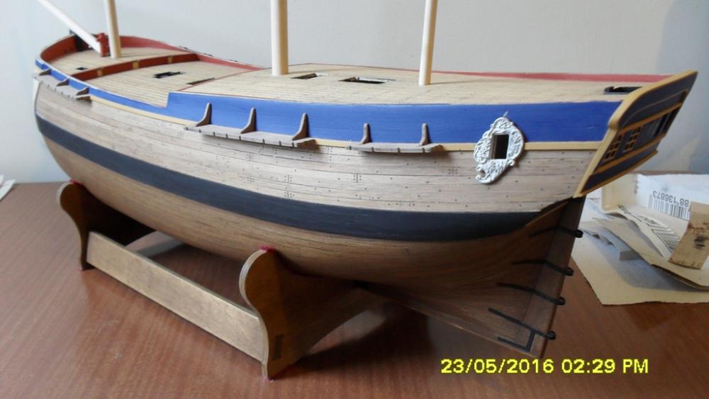

-
Mast Lengths and their above deck heights for HMB Endeavour
dashi replied to dashi's topic in Masting, rigging and sails
Thank you Druxey for taking the time to check my figures and independently confirming the standing height of the mizzen above decks to be around the height of 38'. The foremast: The Woolwich dimensions of the standing foremast are 21 yards and 26 inches or 64',2" with a diameter of 19-3/4". If I have done the math right then this would bring it's top to almost the same level as the main mast which I don't think is correct. If I use the formula of 8/9 of the main mast then it drops it by about 1 yard or 3 feet which is the height I think it should be relative to the main and mizzen standing parts. At this level it also brings the main top mast stays and fore stays into a straighter line running down to the bowsprit.- 63 replies
-
- 1
-

-
- HMB Endeavour mast lengths
- above deck mast heights
- (and 3 more)
-
Mast Lengths and their above deck heights for HMB Endeavour
dashi replied to dashi's topic in Masting, rigging and sails
Druxey Woolwich gives the mizzen as Length 50'-5" Diameter 14-1/6" but at which point it doesn't say.- 63 replies
-
- 2
-
-
- HMB Endeavour mast lengths
- above deck mast heights
- (and 3 more)
-
Mast Lengths and their above deck heights for HMB Endeavour
dashi replied to dashi's topic in Masting, rigging and sails
Cheers Steve. I can't make out any mast steps. Just a series of asterisks marking an imagined line of the mizzen which are non technical so don't really mean a lot. I also remember reading that draughting linen wasn't used until much later so it's generally not considered an original draught. The AOTS book has the masts stepped on the keelson but also suggests the mizzen could have been stepped on the lower deck. Thanks Robin.- 63 replies
-
- 1
-
-
- HMB Endeavour mast lengths
- above deck mast heights
- (and 3 more)
-
Mast Lengths and their above deck heights for HMB Endeavour
dashi replied to dashi's topic in Masting, rigging and sails
Steve thank you for sharing these draughts. Your top drawing confirms the taller mizzen using the chainplate angles very nicely Steve. Do you have the draught 3814c Robin is mentioning, or come across it showing the mast steps? Yes very confusing and it seems we are working off the same plans marked as fitted. I think my kit is using the intermediate plans with the earlier channels etc. Robin could you put up a link to this draught or post it so we can all see it? Druxey which formula would you like to use?- 63 replies
-
- 1
-
-
- HMB Endeavour mast lengths
- above deck mast heights
- (and 3 more)
-
Mast Lengths and their above deck heights for HMB Endeavour
dashi replied to dashi's topic in Masting, rigging and sails
Thank you Steve. Seeing those photos is very helpful and supports the evidence for the taller mizzen. Can you confirm my finding of using the as fitted 1768 draught mizzen chainplate angles to get an approx mast height? -
Mast Lengths and their above deck heights for HMB Endeavour
dashi replied to dashi's topic in Masting, rigging and sails
The only original Endeavour draughts that I am aware of can be found at the Greenwich Museum if you follow this link and search Endeavour. If I had found mast steps then the mizzen question would have been answered there and then. I hope I've understood you? http://collections.rmg.co.uk/collections.html#!cbrowse -
Mast Lengths and their above deck heights for HMB Endeavour
dashi replied to dashi's topic in Masting, rigging and sails
Cheers Druxey. What you are now agreeing to is that there were exceptions which I have confirmed following your suggestion. Below are some links. To clarify: Why I am assuming or even proposing that the standing mizzen mast was deck stepped as opposed to keel stepped is based primarily on the Woolwich measurements. The mast diameters given by Woolwich. The 3/4 of main mast rule compared with the 6/7 of main mast rule for standing mizzens which give respective approx lengths of 50 and 60 feet and which if the first were lower deck stepped and the second keel stepped have the mizzen cap at approx the same height. The Rigging of Ships: in the Days of the Spritsail Topmast, 1600-1720 page 17 which states that the mizzen was either stepped in the lower deck or the keel and supports my suggestion that there were differing ratios for comparing the respective heights of standing masts on a ship. Keel stepping a 50 foot mizzen wouldn't even come close to any of those ratios so this isn't a reasonable option unless Woolwich has made a mistake as some theories suggest and which I don't have a problem with either if the evidence supports this. The charts that have been provided by Wayne which support a standing mizzen of around 60 feet of comparable vessels (which I would assume to be keel stepped otherwise the spindly mizzen would be as tall as its thicker main mast) and the Cruizer draughts of 1752 which clearly show a deck stepped mizzen. Gallion with mizzen stepped in Orlop deck. https://www.google.co.nz/imgres?imgurl=https%3A%2F%2Fs-media-cache- ak0.pinimg.com%2F736x%2F93%2Fa6%2F42%2F93a6420ea5bfdd3f40eed980e3cdee8b.jpg&imgrefurl=https%3A%2F %2Fwww.pinterest.com%2Fpin%2F279082508131417396%2F&docid=j-yuD_1a6gE3uM&tbnid=96F6k4BW9Mf4oM %3A&w=736&h=603&bih=675&biw=1280&ved=0ahUKEwj2iJbB3PHMAhXCYaYKHdJRCDQ4ZBAzCEwoRzBH&iact=mrc&uact=8 The Rigging of Ships: in the Days of the Spritsail Topmast, 1600-1720. Page 17 Cruizer (1752) [alternative spelling: Cruiser] http://collections.rmg.co.uk/collections/objects/84759.html Robin you are agreeing with Druxey's second statement which is fine. As for gender related remarks, they are not relevant or welcome and if not careful could be easily taken the wrong way and cause offence. Let's leave it at that eh!- 63 replies
-
- 1
-
-
- HMB Endeavour mast lengths
- above deck mast heights
- (and 3 more)
-
Mast Lengths and their above deck heights for HMB Endeavour
dashi replied to dashi's topic in Masting, rigging and sails
Thanks Wayne. I've already seen these and although there is some variation they are very close to the Woolwich measurements with the exception of the foremast which I've I've attempted to answer. Knowing the ratio between the standing mast caps would be a help. But to work this out you would need to know their heights above the water line or know at what height on the keelson each is stepped as I have attempted to do here with the Woolwich measurements. Robin (or anyone who is willing and able) it would help if you could find out the differences between the standing (lower) mast caps for each of the above ships you have mentioned? For example in my figures the main mast is 4',7" taller than the foremost to the water line and 10' taller than the mizzen to the water line. I could be wrong but I would expect to see a relationship of this ratio to other ships of Endeavour's tonnage. Cheers Dashi- 63 replies
-
- 1
-
-
- HMB Endeavour mast lengths
- above deck mast heights
- (and 3 more)
-
Mast Lengths and their above deck heights for HMB Endeavour
dashi replied to dashi's topic in Masting, rigging and sails
Cheers Wayne. I'm just trying to point out a connection to the Woolwich mast lengths and a formula which supports their measurements and which by chance happens to be Steel's. If you can replicate these figures using another source then be please do. Regarding the stepping of the mizzen mast I am not assuming it was restepped from the hold to the lower deck, but have given reasons for it to be already stepped in the lower deck at the time of the navy's refit. As you point out why go to all that bother when you can use the 6/7 rule and use a replacement mast at 59',2" which still gives approx 38' above the quarterdeck which I did the math for in posts #1 and #3. All I'm interested in answering here are the heights of the masts above their respective decks as my Caldercraft kit scale is inconsistent and needs constant checking. The only reliable source as to these measurents of Endeavour's masts and yards are from the Woolwich Yard. So part of my research into anything would be re miss if I didn't check the Woolwich yard figures where they don't match conventional belief. The results of which I've posted here to share.- 63 replies
-
- 2
-
-
- HMB Endeavour mast lengths
- above deck mast heights
- (and 3 more)
-
Mast Lengths and their above deck heights for HMB Endeavour
dashi replied to dashi's topic in Masting, rigging and sails
Thanks Druxey can you provide references for this? If this is the case then how do you explain the evidence of the mizzen chainplate angle on the as fitted draught of 1768 coupled with Steel's reference that the mizzen is stepped in the lower deck which then matchs Steel's formula to the Woolwich mast lengths with the exception of the foremast as I've already outlined and explained? Also Steel does give another set of formulas and in it the mizzen mast length is 6/7 the length of the mainmast = 59',2". The keelson measures 22' below the guarterdeck at the mizzen. So 59',2" - 22 = 37',5" for the mizzen height above the quarterdeck if stepped in the keelson following this formula. Therefore I think this supports my previous calculations for the mizzen above deck height of 38' and the theory that the Endeavour mizzen as fitted 1768 using the Woolwich length was stepped in the lower deck.- 63 replies
-
- 2
-
-
- HMB Endeavour mast lengths
- above deck mast heights
- (and 3 more)
-
While researching the mast lengths for my HMB Endeavour build I came across an online copy of David Steel's The Elements and Practice of Rigging and Seamanship 1794. Here is the link: http://www.hnsa.org/resources/manuals-documents/age-of-sail/the-elements-and-practice-of-rigging-and-seamanship/page-1/ I am finding this to be a great resource even though it is a later compilation from different sources (there are other formulas which varied between shipyard and country during that time) because it has helped answered the tough questions I was having regarding the mast lengths and their respective heights above deck and outboard, which are important to know for the model builder. But to work this out I first needed to know where each mast is stepped. Currently no plan has been found showing the mast steps and below deck stanchion bracings. I finally found the answer in the opening chapter of David Steel's Mast Making Vol.1 which clearly indicates that the fore and main mast's are stepped on the keelson while the mizzen mast is stepped (or more correctly can be) on the lower deck. From this discussion we have located other sources which independently support stepping mizzen masts in the lower deck. The stepping of mizzen standing masts in the lower deck is also supported in William Mountaine 1761 'The Seaman's Vada-mecum and defensive war by sea', and other NMM ship plans prior the 1764 construction of Bark Endeavour. Working back from the 1771 Woolwich Yard mast measurements I found one set of Steel's formula to give me a very close match to these measurements as there are several formulas to choose from but only one set that appears to fit. Remembering that in 1764 ship building was still an evolving art which varied between country's and ship yards while Steel's work didn't come out until 1794, 30 years later. Given this time lag I think it is reasonable for there to be some lee way in interpretation and use of these formulas. With this in mind here is my math: Main Mast (whole length): Wooldwich Yard 69',4". Formula: L = Length, B = Breadth, L+B/2 To get this to work I've assumed L to be the measurement from stem to stern instead of the gun deck which Steel uses. The gun deck could could have become the standard in 1794 but might not have been in 1764. L @ 109' (approx) + B @ 29',2" divided by 2 = 69' (very close to Woolwich @ 69',4"). Stepped on the keelson @ 20',6" below the quarterdeck. 69',4" - 20',6" = 48',8" height above quarterdeck partners. Foremast: 8/9 of mainmast = 61',6". Woolwich Yard 65',4". Woolwich measurements are in yards @ 21yards, 28inches which would bring the foremast to almost the same height above the waterline as the mainmast and giving it a height of 47',4" above it's partners on the forecastle. (I have since revised this and the foremast looks to be close to within normal ranges at 65'4" compared to the main mast making it's cap around 2.5 feet below that of the main mast cap). Mizzen mast: 3/4 of mainmast = 51',11". Woolwich Yard 50',5". Stepped in the lower deck @ 12',6" below the quarterdeck gives a height of 38' above it's quarterdeck partners making it's cap around 8' below the main mast cap (within so called 'normal ranges') Bowsprit: (whole length) 3/7 of mainmast = 29',8". Woolwich Yard 34'. This does not match until we work out the outboard length which is 3/4 of 29',8" = 22',4". Considering where the bowsprit is stepped in the fore topsail sheet bits then @ 34' it achieves this outboard length of 22',4". The contemporary evidence critically examined in this discussion reasonably and logically supports that the 1771 Woolwich Yard measurements are accurate to within reason. The critical missing peace of the puzzle was that the mizzen might have been stepped in the lower deck and not the keelson as suggest by some late 20th century research. I almost missed this myself until I later searched for it as I realized with out this information I couldn't make sense of the Woolwich yard measurements because stepping the mizzen on the keelson at that length just wasn't meeting up with the angle of the mizzen chainplates from the as fitted draught of 1768. And would make the Mizzen cap 18' feet lower than the Main cap which just isn't the case in contemporary drawings and paintings attributed to Sydney Parkinson from Cook's voyage and nor is it within a so called 'normal range'. Where as stepping the 50'5" Mizzen in the lower deck brings it's cap up by 10' to within this normal range. I apologize for any inaccuracies.
- 63 replies
-
- 3
-
-
- HMB Endeavour mast lengths
- above deck mast heights
- (and 3 more)
-
Hi Pat. According to both the AOTS Endeavour and Rigging of Period Ship Models by Lennarth Petersson the parrel ropes were seized around the yards. Like you I make a working rig and have found it best to seize one end of the parrel rope to the yard away from the ship and the other with the yard in it's lowered position along with the halyard tyres. Hope this helps but sounds like you are on the right track.
-
Cheers Dave. I went over the figures again and what if the foremast were 20 yards instead of 21? If this is the mistake then everything else just about falls into place to within kooie. It would bring the foremast down to 62' 2" bringing it closer to Steel's spec of it being 8/9 the length of the mainmast and the stays would be inline? Just a theory. Plus this would also explain the diameter of the foremast compared to the mainmast and why the foremast only has one set of back stays where as the mainmast has two sets which wouldn't make sense if both masts were close to equal hight. This could also be the main reason why everyone adds the extra back stay to the foremast when the 1768 as fitted draught only has one back stay on the channel?
-
Dave I've found some more information from Steel 1795. https://books.google.co.nz/books?id=T2QMBAAAQBAJ&pg=PA56&lpg=PA56&dq=bowsprit+lengths&source=bl&ots=YURlDL7ue1&sig=bCE098TuEb3cEk-KrzCZQEoi4uY&hl=en&sa=X&ved=0ahUKEwiRtZO18OvMAhXiKKYKHcFZCkMQ6AEIPDAI#v=onepage&q=bowsprit%20lengths&f=false Bowsprit, whole length = 3/7 of mainmast; outboard = 3/4 it's length; diameter = foremast. Mainmast (whole length) = ship length + breadth /2 The math: Mainmast; 109' + 29' / 2 = 69' (matches Woolwich Yard 1771) Bowsprit; 3/7 of 69' = 30' (4' short of Woolwich Yard 1771) Bowsprit outboard; 3/4 of 30' = 22'6" (matches outboard of 34' bowsprit from Woolwich Yard 1771) Hope this is helpful and I apologize if it's incorrect, so please check my figures and research. Footnote: According Steel's charts the Woolwich Mizzen length is correct in which case it's likely it was stepped in the lower deck to give a hight of 36'6" above the quarter deck. This is the only way I can account for the angle of the mizzen chainplates from the as fitted draught of 1768. Great build by the way, Dash
-
As I'm currently sidetracked looking at mast lengths for my build I'm finding this post interesting and so have done a little research. 'Ship Model Builders Assistant', by Charles G. Davis has some charts of American ships with their respective specifications. From this I found a packet ship very close in size to HMB Endeavour named the Courier, length 116 feet, tonnage 380, fore mast 58', main mast 60', mizzen 54' and bowsprit outboard 20'. The AOTS bowsprit outboard (measuring from stem to bowsprit cap) is at 21-22' so within kooie of this. I'm sold on the taller mizzen which can be checked by the angle of the chainplates on the 1768 as fitted draught, but I'm still not yet sold on this longer bowsprit. I think it is definitely worthy of more research with cross referencing of that 1994 report if you havn't already done this.
-
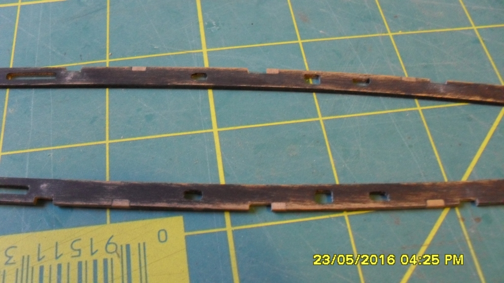
Thanks Scott. Dave thanks for pointing that out and it was at the back of my mind also. I've trimmed about 1mm off and if I rebate then I could lose some more so last night decided to butt them against the sheer strake as each channel has standards on it's upper which I'm thinking will help to support them. To do this I held some 180 grit sand paper over the sheer strake while I sanded the inner edge of each channel to fit the curve and angle. Next I think I might need to fit the standards so I can sand these against the wale for a nice fit and to get the correct angle before pinning because my eyesight seems to be getting worse and I'm having trouble getting the pins and pin holes in straight.
-
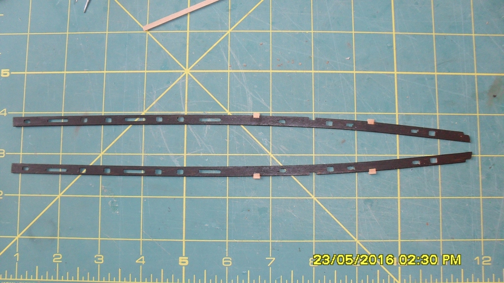
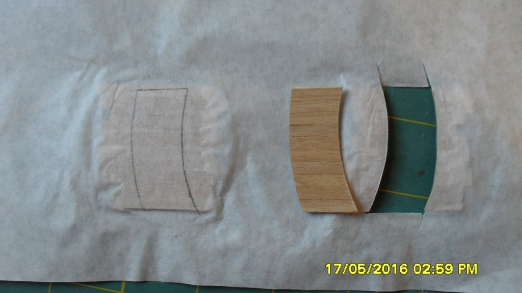
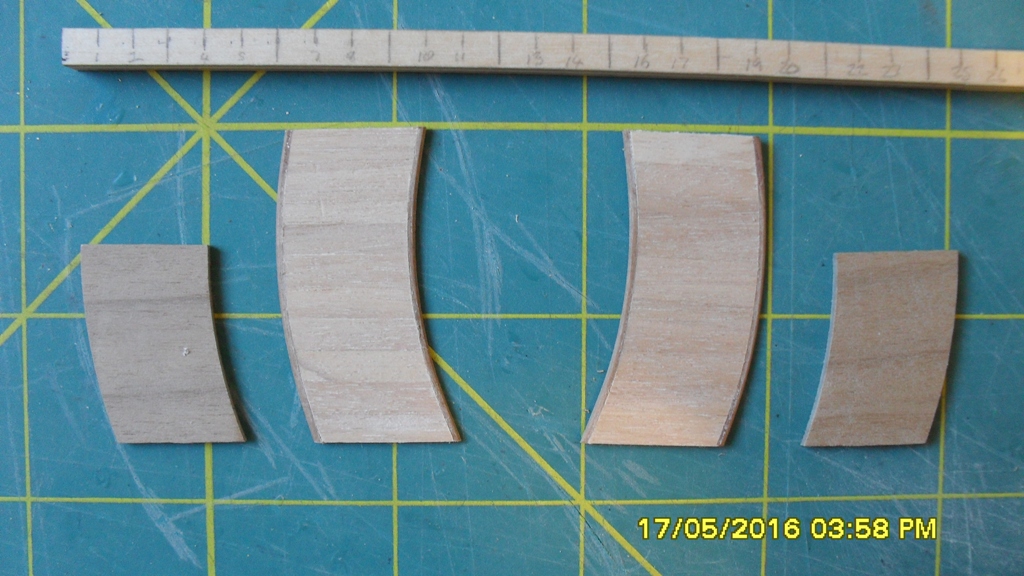
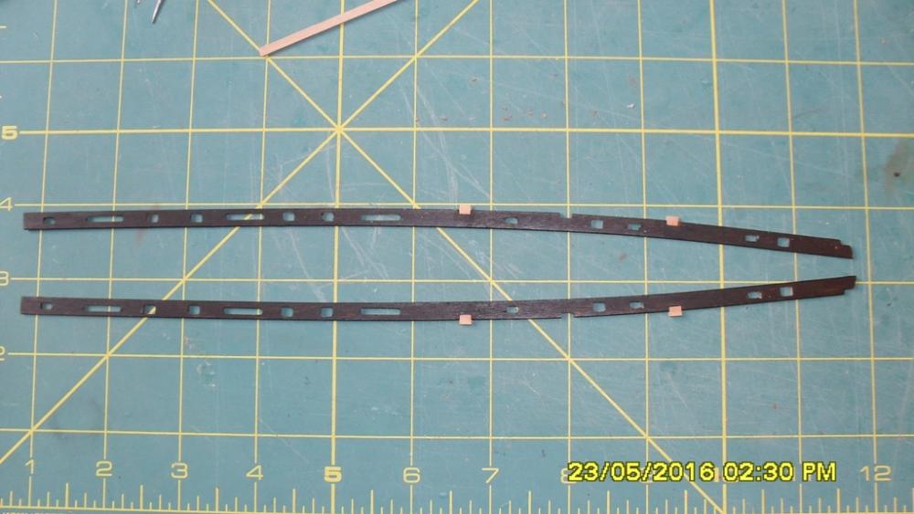
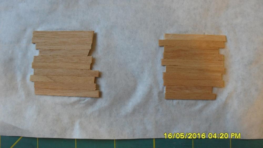
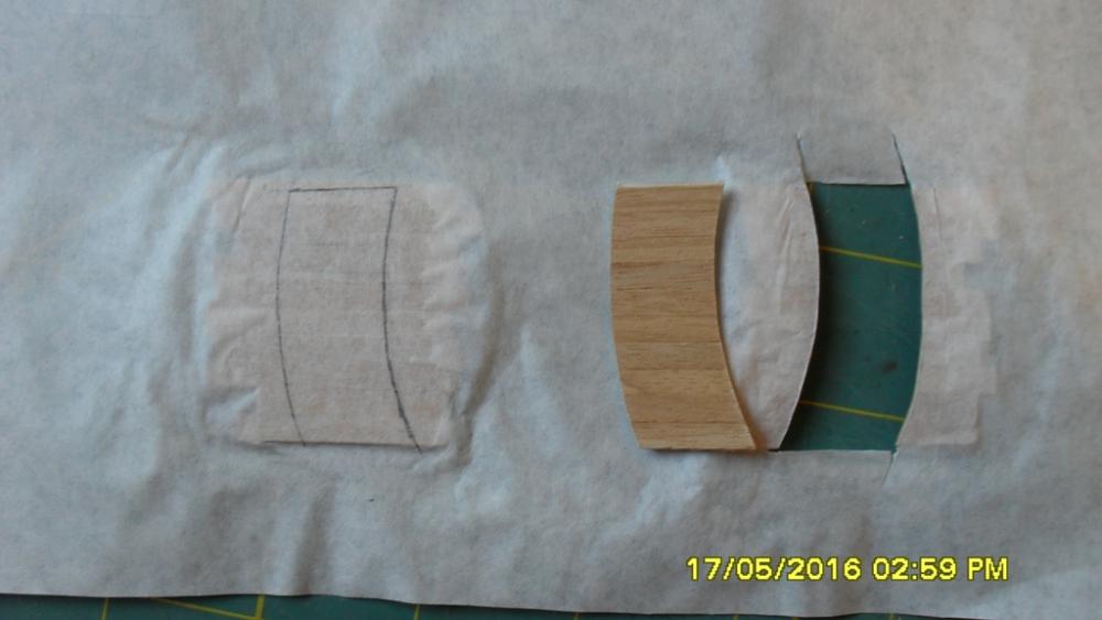
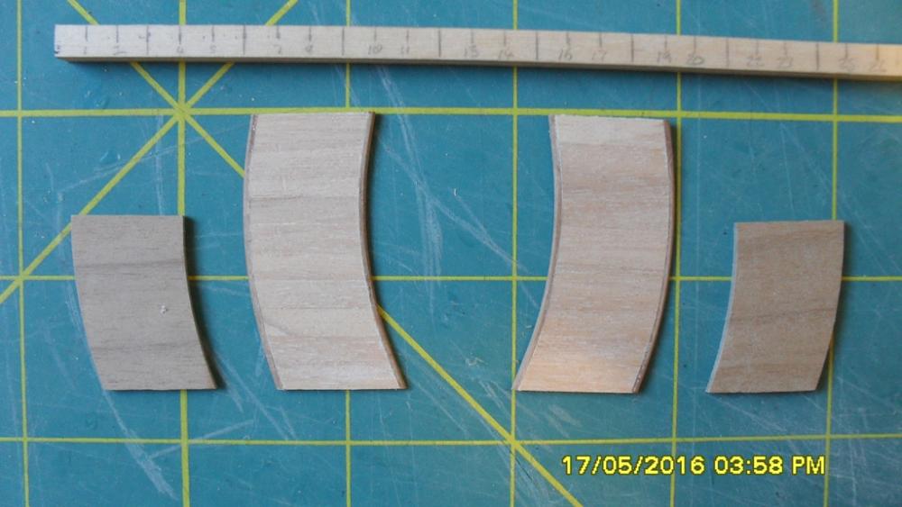
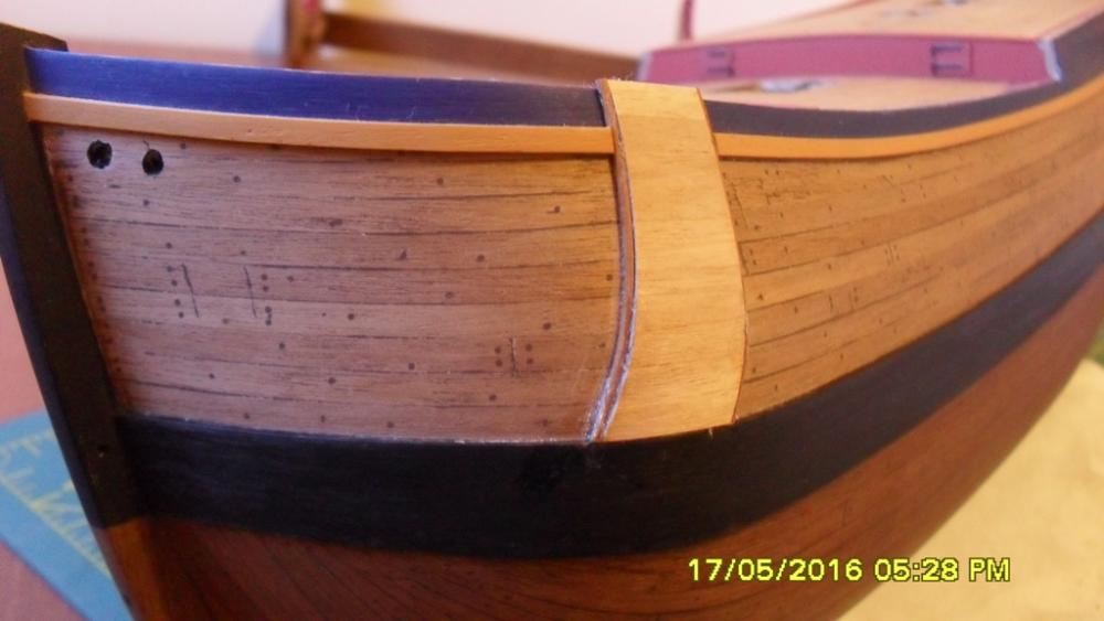
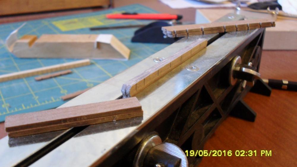
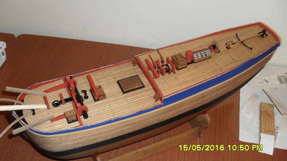
Anchor linings: Because the laser cut linings were too short I needed to bash some replacements. As I couldn't find how to do this else where I decided to document it and if it worked then post what I've done here. I decided to use some decking off cuts as this is soft and would bend easier around the shape of the bow. So first I marked out the shapes on some tracing paper (lunch wrap) and then glued the decking pieces to it with white glue. When dry I carefully cut around the shapes and sanded both to be an even match. Using 1x1mm walnut I made the edging and used contact adhesive (shoe glue) to bond these to the linings. I also used contact adhesive to then glue the linings to the hull. This was the part I was dreading and my fears were justified when the corners of the linings wanted to try and lift so I carefully inserted some ca glue in the crack and applied pressure by hand until it had grabbed. Channels: Due to the chainplates not matching their respect positions in the channels from the 1768 as fitted draught I decided to plane the edges down and file some new chainplate slots. Also using the spree that the channels came from I managed to bash another set of mizen channels because as I mentioned earlier the kit laser cut ones look like they were from the 1768 Earl of Pembroke draught and not the 'as fitted' Endeavour draught. The replacements are considerably longer at 10' and slightly wider. Next is to briefly soak and shape each channel to match the curve of the sheer strake and then decide whether to butt them on the sheer strake of check them into it?

-
Almost ready to fit the bulwark capping rail, but have been sidetracked by the channels. I might need to check the channels into the top of the shear strake in which case I will hold off on fitting the foreward capping rails as these could get in the way and possibly damaged. I can make up the channels and dry fit them with pins then leave them off until I'm ready to fit the chain plates. looking at the channels I discover some discrepancies with their sizes on the kit plans and laser parts especially the mizen channels. Further research revels that the kit and AOTS book have for some unfathomable reason fitted the Earl of Pembroke mizen channels which are smaller and start further abaft of the mizen compared to the 1768 as fitted draughts. So I will need to bash some replacement mizen channels and will fit them according to the 1768 draught. There is also a discrepancie with the forward channels and deadeye's so will attempt to follow the as fitted draughts for these also, kit parts permitting. I know there is controversy over the correct hight of the mizen which I don't wish to re-hash, so at this stage will err on the side of reason and go with the longer measurement as suggested in the AOTS book which puts it's hight at 36'6" above deck. This is considerably taller than the kit has so to check this against the 1768 as fitted draught, I approximated the hight of the mizen by taking a line of the angle from the chain plates to where it would intersect the mast projecting at the angle drawn leaving the deck and the AOTS hight seems to be a very close match.
-
Thanks for the likes. Thanks Chris. Yes I will be bashing the knightheads, out of the old windlass standards that I replaced, because the kit ones are too small. In the AOTS book page 33 the larboard bow sketch by Parkinson which depicts the bumpkins also has the knightheads with a cap over the bowsprit. This appears to be how they have it on the replica. The next pages to look at are 53, 58, 75 and 90. Page 75 shows how the tack bumpkins pass over the bow but I don't know how accurate this depiction is. I have my tack bumpkins at 36 degs off the sides of the bowsprit so they will pass over the bow closer to the knightheads and look as close as I can get to Parkinsons sketch on page 33 of the AOTS book. Also in this position their stays should be clear of the cathead or anchor tackle and the anchor cable can hang under them if it's attached.
-
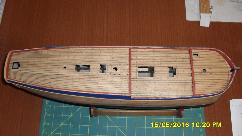
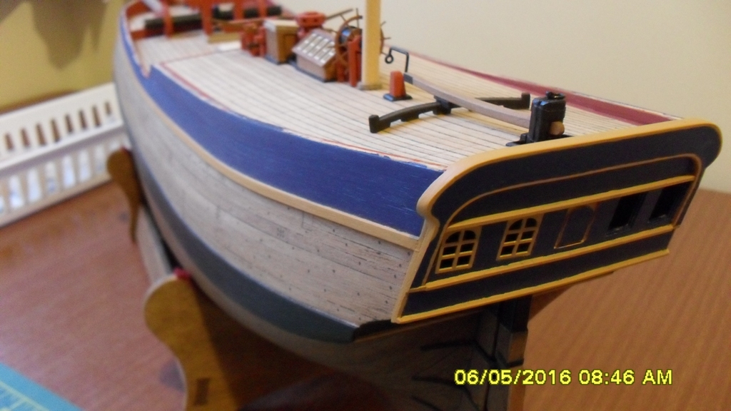
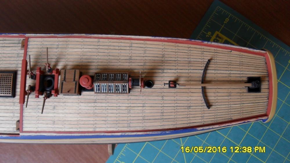
Thanks for the likes and comments. Deck: With most of the deck furniture complete I was now happy with the location of the beams so proceeded to paint in the trennels and butts using artists Indian Ink permanent markers using the replica hull as a guide. After completing that I discovered that the ink was smudging when I came to erase the pencil lines and the only way to remedy the situation was to wipe the decks down with methylated spirit to remove all the ink. Oh well that didn't work. The best plans are only as solid as if written on water. So back to the tried and true 2B pencil. Fortunately the ink had very faintly penetrated the deck where I had marked the trennels and butts otherwise I would have lost my beam lines. All I had to do was mark over them where I had before using the pencil and then seal it all with it's second coat of matt poly. Wiping off the ink seemed to create a slight yet unintentional weathered look which I'm happy with so it all worked out in the end. Next is the bulwark capping or false rail as it can be called and the anchor linings which I might do first. All the deck furniture is only dry fitted so it will be removed to a tray for safe keeping.

-
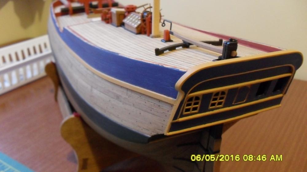
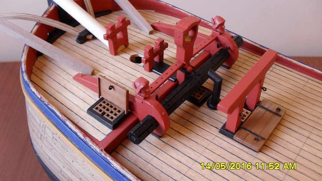
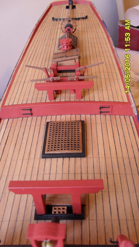
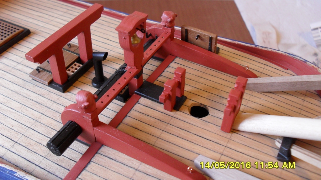
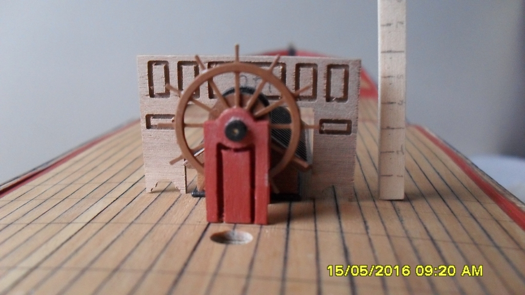
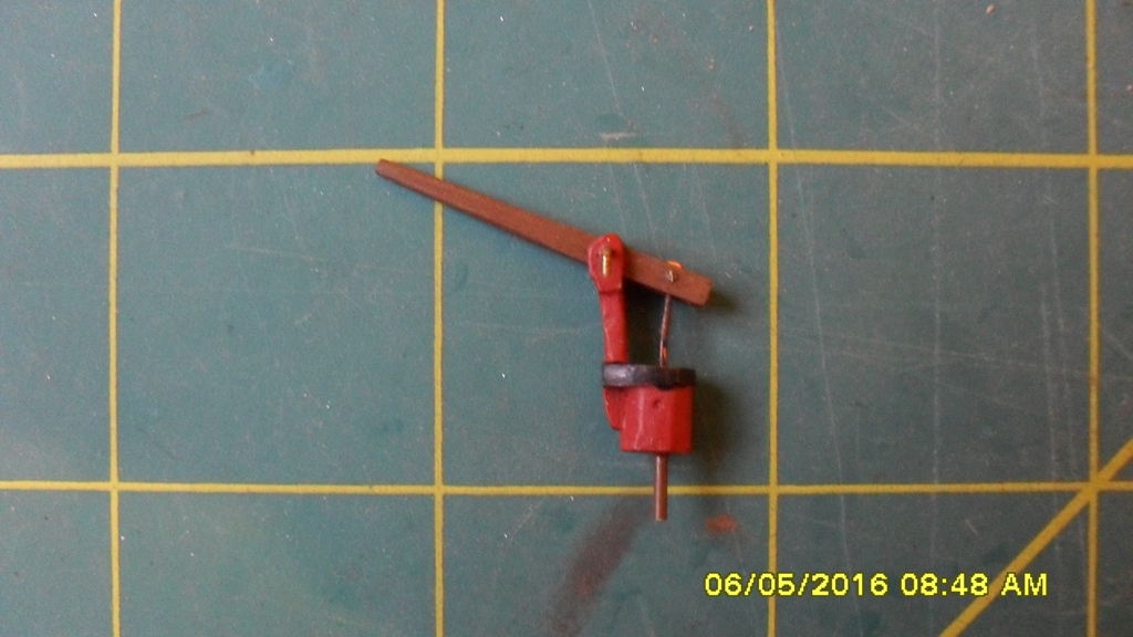
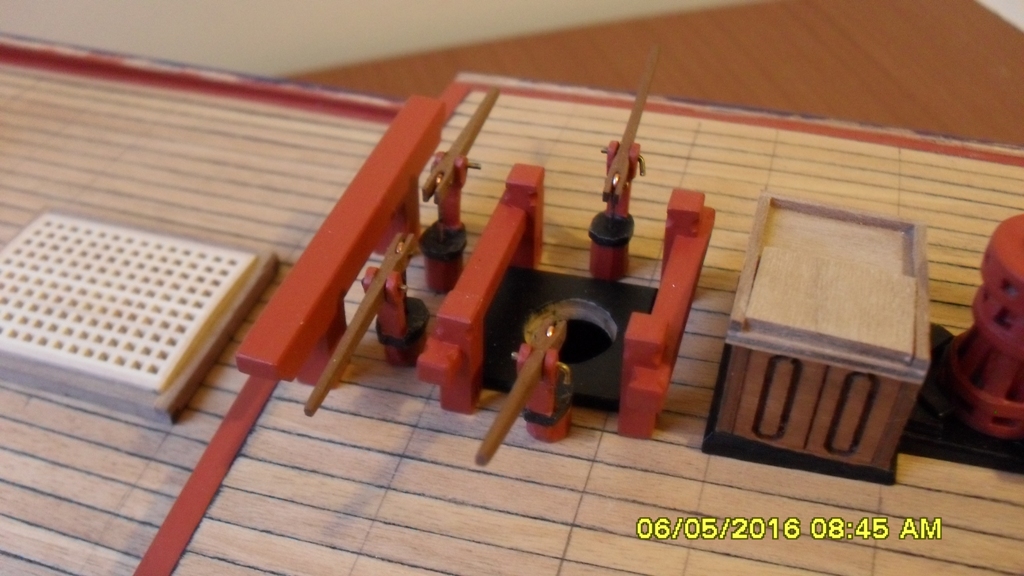
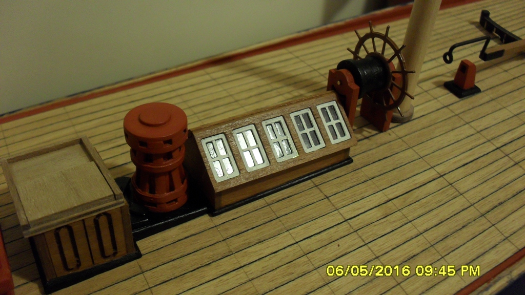
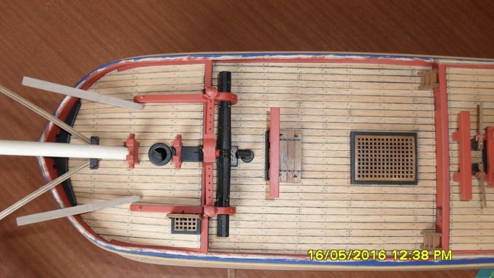
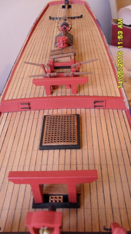
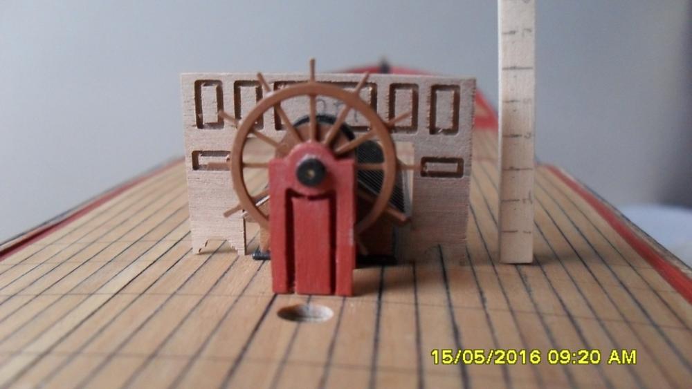
Update: I don't know how accurate any of this is but here is my best guess based on what information I've managed to find or research. Bashed hatchway covers. I used the extra open hatch hinges in the kit. I made the lids/covers out of 1x4mm walnut from the kit and some of my own 1x1mm walnut. On the navel draughts there appears to be a breast hook on the upper deck of the forecastle. So I bashed this and trimmed the exposed stem inside the bulwarks to match the draught. Under the fore gallows I've included a bolster for the anchor cables to run over and bashed the coaming to suit. The companion/skylight: I've painted the metal grating surround walnut to represent wood with iron straps painted black. So black iron straps fitted in a wooden surround which I think might be more appropriate for the date. Binnacle: As you can see from the photo the kit supplied binnacle stands 6 foot tall and not only blocks the view of the helmsman but also the some of the skylight. So I will bash a much smaller binnacle based on pictures and plans I've managed to find as it was the compass housing and would have had a lamp and flu in the top to light up the compass at night which was housed in the base with a viewing shoot for the helmsman. It probably stood only around 3 foot tall and 18" square.


-
Thanks Chris. Thanks Steve I am impressed with the quality of your build. I'm not sure about the CC kit companion either but I wanted to build it. Yes those iron bars don't make a lot of sense for their time as iron wasn't as strong as it is today and it would have been a lot of weight. As a compromise I've painted the brass surround walnut to represent the bars as black strapping in a wood frame but I havn't posted any pics of these yet. But I agree it could have been the same as the replica with a wood grating. From the deck draught it looks as if it slightly tapers towards it's aft as the deck rises. The only thing that I can think might cause this is a roof that has a level ridge line fitted directly to an angled deck. What do you make of the taper? Maybe another discussion topic so we can colate information? Regarding the fore tack bumpkins. I mentioned in an earlier post that I have a working theory based on a scetch from the time and think they should be positioned closer to the bowsprit at around 36 deg from centre leaving room for the seats of easement whilst clearing the cathead tackle. In this position I think they can also be shortened but I won't be up to finalizing that until after the false rail is fitted. Thanks Paul for the heads up about those pumps. I might try and hold off glueing them in position for as long as possible so I can move them out of the way for rigging.
-
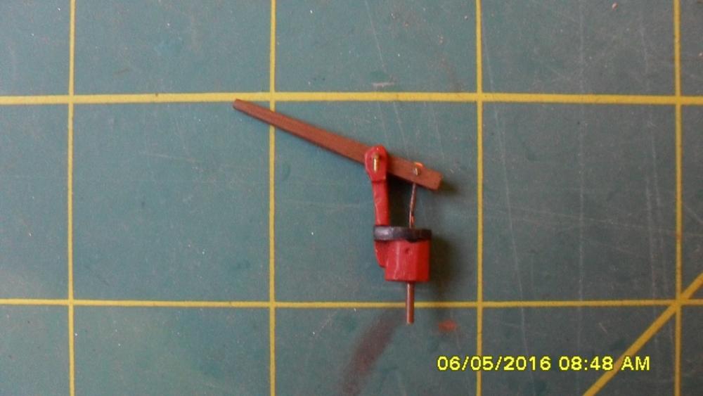
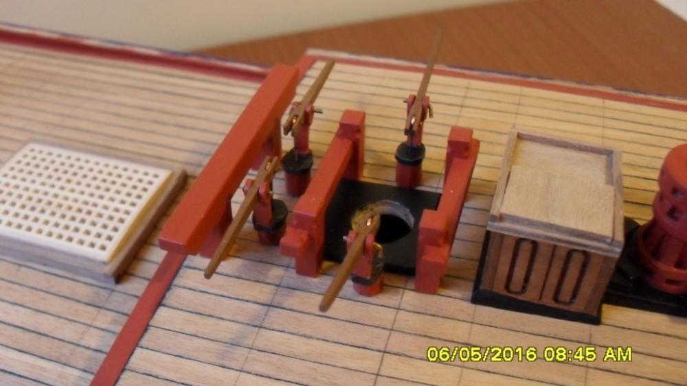
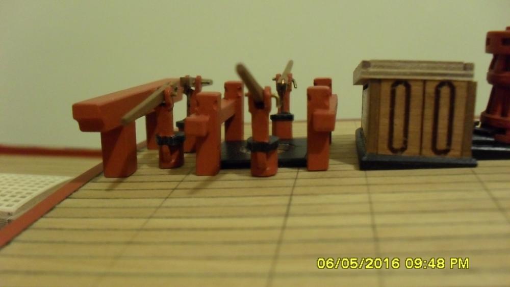
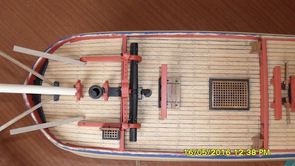
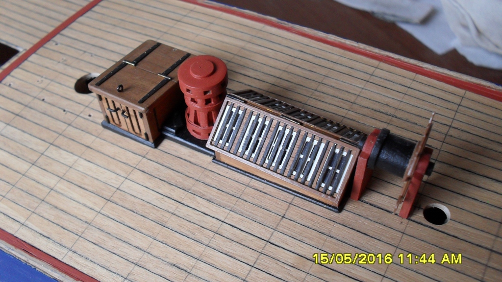
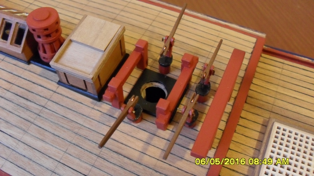
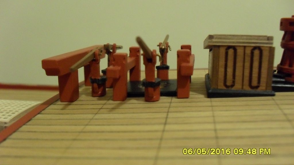
Small update: Pumps and skylight or companion as it's called in the 1768 draught. After several attempts with the kit pump I managed to file it down to a shape I can live with. I used a slightly larger dowl than the kit instructions so I could file it octagonally. I also filed the metal pieces into what I think is a closer shape to the photos I have researched. But I couldn't live with the kit handles so bashed some out of a nice length of 2x2mm walnut which I already had on hand. With the the companion/skylight and quarterdeck hatch I had a moment of madness with the pigmented stain and surprised myself with the result. The companion windows next I tried different colours but settled on white. So after painting I removed them from the spru and filed them to fit snuggly into the roof. For the glass I ca glued them to a sheet of clear film I bought from the stationers. When it had dried cut them off around the frames using a new blade. After a slight filing I dry fitted them and touched up the white. As part of the process of choosing the colour for the companion window frames I dry fitted two of the great cabin stern window frames which already I'd decided to paint yellow ochre. Now I'm completing the hatches and bashing hatch covers as it makes sense to finish the deck furniture before I finish the deck while I'm constantly dry fitting stuff incase I make any mistakes or have any accidents.