


Beef Wellington
-
Posts
2,249 -
Joined
-
Last visited
Content Type
Profiles
Forums
Gallery
Events
Posts posted by Beef Wellington
-
-
Hi gunslinger, just found your log. Your Badger is coming along very nicely, look forward to more progress pictures.
-
Appreciate your motivating comments chaps!
Robert - coming from you and what you've done with your Mars that is high, probably undeserved praise. I can only aspire to what you've acheived.
Jean-Pierre - thanks for stopping by and the kind words. I did my best to ensure the chains were symmetrical and they look fine in person, however they never quite seem to look look right in photos, must be because of all the angles involved. I don't have a lot of prior experience, the usual Airfix plane and tank kits growing up, and of course HMS Victory (think it was 1:180). My last complete model was 20yrs ago,1:96 Revell USS Constitution, I was happy with it at the time but I'm sure if I looked at it today I'd see a lot of things I'd want to do better. I started the Billings Bounty 15 or so years ago and really got no further than the framing as instructions were poor and I couldn't figure out the basic planking and failed horribly! It wasn't until I found MSW that I got the courage to try again with the wonderful support and help from its members that really helped de-mystify the hobby.
Carl - I built the table for practice

Jim - I'm with you on the Carronades, this seems to be the next 'daunting' task which I wan to get started on soom
-
M - thanks for watching over my shoulder
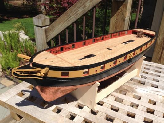
When you have a chance, perhaps an overall shot showing the recently installed capping rail throughout?
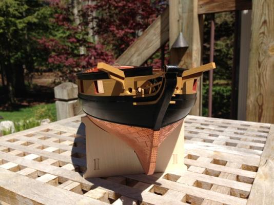
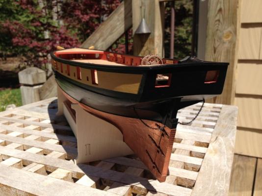
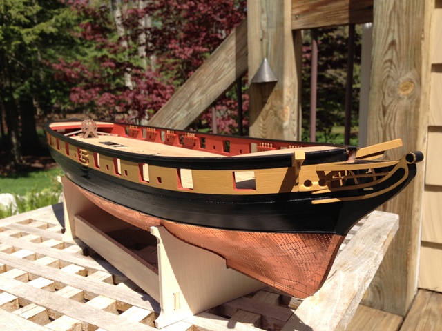
Robert, here you go, hope you're not disappointed...she had her first trip outside for some beauty shots. The Snake doesn't have the most beautiful lines of the other ships on here (Mars and Pegasus esp.), but maybe a certain "utilitarian elegance".

- ccoyle, Ferit, chris watton and 4 others
-
 7
7
-
Maurice, Robert, Carl, appreciate you checking in and the advice.
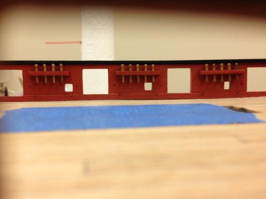
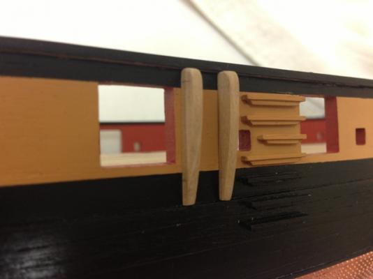
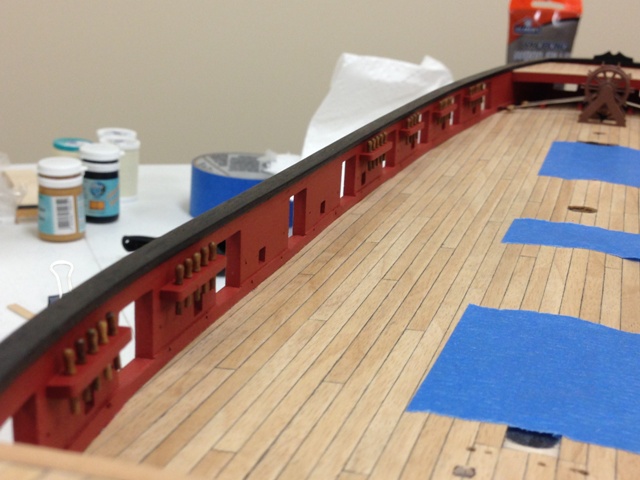
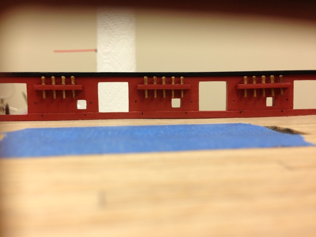
Finished the starboard pinrails, couple of things to note (mainly for my own benefit when I refer back to this)
- Two brass pins were used in each pinrail as recommended to take any strain from rigging
- Once the right height had been determined, I made a block that could be placed on the deck to ensure each pinrail was a consistent distance from the deck. The height chosen ensure that there is sufficient clearance from the capping rail, and no interference with the sweep ports
- Putting bit of pressure on pins attached to the pinrails was sufficient to make small 'locating' indents in the bulwark that could then be drilled out properly before gluing.
- Installed the belaying pins once pinrails were fixed and painted. Once again, these are not the kit supplied pins, they are the aftermarket Caldercraft ones offered in their newer kits, a cheap but worthwhile upgrade in my humble opinion.
Glad I deviated from the plans, second photo shows that there is a more workable distance between the belaying pins and the bulwark which will hopefully allow me to coil some ropes on here when I get to the rigging.
Will be travelling next week so will need to put tools down until I get back, but pretty pleased with the way these turned out. Shes starting to feel a bit more like a ship and not just a hull.


-
-
Thats a nice looking rudder Stergios, glad you're back in the shipyard.
-
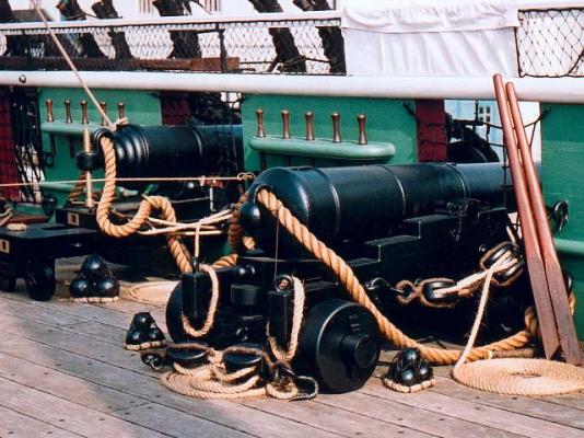
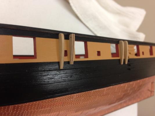
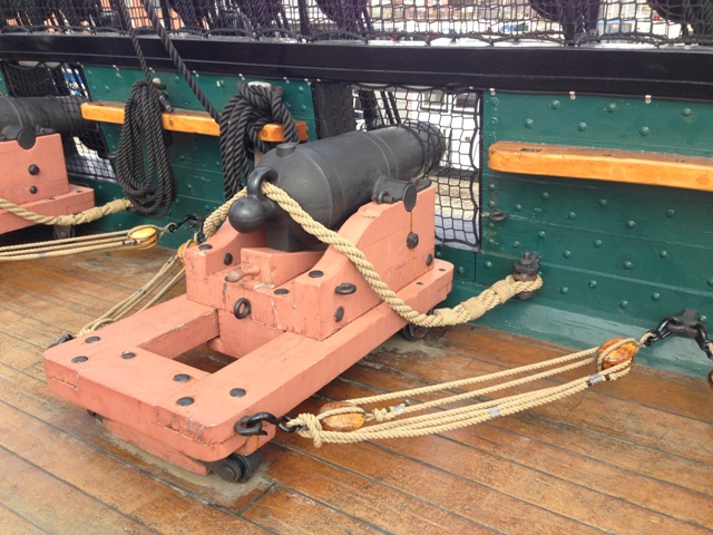
I seem to have reached a stage where there are now many options open to me on how to proceed, and have had difficulty deciding how I wanted to attach the bulwark pinrails. The plans indicate that these should be fitted directly under the capping rail, however everything I've seem indicates that these should be mounted lower (pics below of Trincomalee and Constitution).
Mounted one set to see how it looks and think this is how I will proceed, these are at 3'5" (~1m) actual height above the deck which seem to tie in with the real life examples. Another reason for choosing this height is to ensure that the belaying pins don't interfere with the capping rail overhang nearer the stern where the bulwark height is less than the bow.

-
Brian, here's how I tackled it on my Snake. I'm not representing that this is 100% accurate but I was please with how it turned out.
-
On your photo the smaller 2mm cable looks more appropriate and does tie in with the beam calculation result.
B.E.as always, appreciate the insight.
-
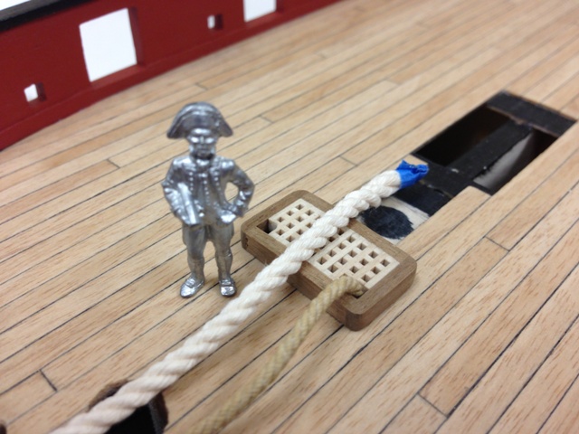
Jim - this is how I was planning to tackle the hawsers and grating. I copied this from a photo from Victory which showed exactly this (of course I can't find it now). You can see the comparison of the supplied 2.5mm and 2mm Amati hawser. Maybe its just the bright white colour that makes it look much bigger.
If anyone has any ideas on hawser sizing for a ship of this size it would be appreciated (Snake is 100' long). 2.5mm scales to 6.3" diameter and 2mm scales to 5".

-
Dave, once again, thanks for posting this fascinating thread. Have you made a decision yet to move forward with a Cruizer/Snake build? There are some great builds going on right now (not counting my own).
-
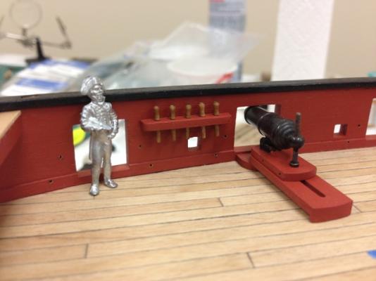
Pelican carried the usual class armament of 16 x 32 pounder carronades, 2 x 6 pound guns (in the bridle ports) and a 12 pound carronade mounted on a gun carriage for use as a boat gun. She also had a pair of 6 pound brass guns, acquired by her captain in Jamaica, at the stern ports and a crew of 116 men and boys.
Hi Molasses, great info. I'm curious where you found information to suggest that the 6lb'ers were placed in the bridal ports. The configuaration you describe would leave a pair of gunports open which doesn't quite reconcile with the her captains apparent love of armament. Not saying you are wrong, just curious as I'm looking to build my Snake with this configuration and was planning to put the cannons in the #1 gunports as there is next to no room to fight a gun under the forward platform.
-
I don't know whether they have been misnamed Jason, ships often have both. A pair of fenders, just forward of the side steps, and a separate chesstree with the sheave, located further forward along the hull to take the Main Tack.
Think I'm good. The plans call for the pair of fenders for'ard of the steps. There is only one other item further forward and it is to take the maintack as you describe, this is what I'm think is mislabled, seems it should be called a chesstree and not a 'hull side fender' (There is no reference to chesstree anywhere). Really appreciate you helping clarify.
-
Love what you've done with those panels, top notch!
-
Hi Jim, even though I'm taking a slightly different approach, I wrestled with this as well. I actually bought some Amati 2mm thread a long time ago to replace the stuff in the kit. I read somewhere on MSW 1.0 that the supplied 2.5mm rope was probably too big for such a small ship (6.3" real scale) and more appropriate for a ship of the line. I'm sure others can comment on the veracity of that, but going with the slightly smaller size would be a solution as this should fit in the grating holes without major surgery.
-
Nice work on the capping rails Jason, and your replacement fenders look better.
I notice the kit part has a 'sheave' hole in it, is this supposed to be a chesstree rather than a fender? they are similar in form.
Appreciate that BE, I'll take that as approval to proceed
 The instructions call them 'side fenders', but I agree with you that they are perhaps misnamed and should be called chesstrees. On my next build I'd like to do some proper sheaves, but I think I can live with drilling holes for now.
 -
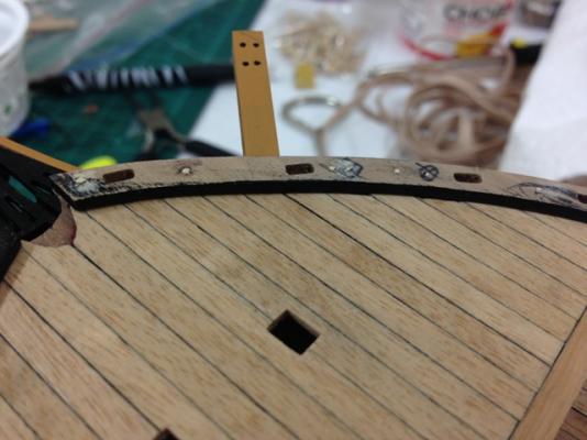
Would appreciate any thoughts or advice here before I get too far - the kit instructions are not much help.
1) Looking to fit the side fender (first picture) - there is actually a pre-cut part but everything I see shows the fenders going from the cap rail to the wale, and this piece is 2-3mm short both on my hull and compared to the plans. I decided to make my own to fit better so that it would fit and used 2x4mm strip to do this and used the pre-cut piece as a guide - this did require some careful shaping to allow for the very slight hull curvature. (both are shown for comparison)
2) All that is said about the waist fenders is to "cut some 2x4mm strip to length and glue in place as per plans". I'm guessing these should have a similar shape and fit to the side fender, does this look correct?
-
Robert, Jim - thanks. Totally agree, getting the cap rail in place really makes the hull feel a bit more final. Was pretty happy how it turned out.
-
Hi Scott, my thoughts as a newbie as well. I thought I would prefer to use CA glue as it seemed much more convenient, but echoing the sentiments of others I've found the PVA to be much more pleasurable to work with and resort to CA only when necessary. I saw a comment recently which I loved which was that CA glue seems to set much to fast when you don't need it, and way too slow when you do.
DanVad in included a good tip which I really appreciated and found helpful which was to coat both surfaces (not using too much!), you can get a good bond surprisingly quickly (nowhere near as fast as CA) although its worth leaving to dry fully to be safe.
-
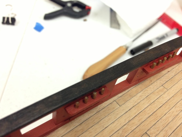
Nothing really revelatory here, but may be useful for others building this kit. You can see the number of pins I used in the bow section to alleviate any lateral strain from forcing the capping rail to match the bulwark shape. I experimented with a couple of different approaches, using the 1mm wire and cutting off the provided pins. I ultimately went with just using the pins as they seem to work just fine. The PVA glue did a really good job holding the lateral forces once left to dry really well, so this is really just insurance.
Basically just removed pins one at a time, cut to length so the end sits slightly below the cap rail surface, glued with thick CA glue and then filled with wood filler.
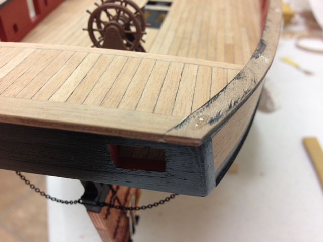
At the stern, the aft cap rail piece was actually much closer in shape than I though, but I made my own piece anyway. The plans seem to call for the aft cap rail to go fully across the stern. As can be seen, I was more concerned with ensuring that the side cap rails were correctly positioned and then dovetail the stern cap rail by repeated sanding and fitting. Once painted, don't think it will really make one bit of difference.
Oh, and I used steam to pre-bend the stern cap first as it was a little short to force, I found this worked really well, it softens up the glue in the ply which can be shaped with fingers easily before it 'sets' again very shortly after.

-
Wonderful Robert, must be a nice feeling to move onto the furniture. I've been secretly 'eyeing' you capping rails, very very nice indeed! Your build really wants to me explore some other woods if I get to another build, the ubiquitous walnut doesn't come close to the beauty of the cherry and other 'premium' woods.
-
Hi Jason
I had exactly the same issues with the capping rail. Main thing to be careful with is to make sure it doesn't overhang inside too much otherwise your pin rails will not fit with the belaying pins in.
I would also recommend permanently pinning as I didn't trust the glue to hold the lateral strain.
Keep it up though!
Hi Jim, all good advice. I tried to keep the rail as even as possible along the length which means a rough 1.5mm overhang inside and and out. Where I this wasn't possible, I looked to make the inside overhang the smaller of the two...fingers crossed. If necessary, I'll probably try to add an some material to the back of the pin rail if needed.
-
Hi Jaison,
Fast question, did you use the wheel supplied with the kit? Your wheel looks a lot better than the kits.
Thanks,
Mort
Mort - I used the aftermarket Caldercraft wheel, otherwise the parts from the kit. I did decide to put the wheel on the inside of the supports rather than the outside as called out in the instructions.
-
Congrats Jeff, do you have to pass some sort of multi day written theory and practical test?


Cruizer-class Brig-Sloops of the Royal Navy
in Nautical/Naval History
Posted
Great info Dave, very interesting. I would agree that there is an opportunity for Caldercraft to offer such a kit that would make it easy to model any one of the Cruizer class - it seems the later Cruizers had the caronnades and often had the fore and aft platforms (paintings of HMS Pelorus illustrate this when she grounded, and interestingly she was ship rigged for a period as well which suggests that masting changes may have been pretty common). Looking forward to the next installment.