


Beef Wellington
-
Posts
2,245 -
Joined
-
Last visited
Content Type
Profiles
Forums
Gallery
Events
Posts posted by Beef Wellington
-
-
-
Love the look Timmo, you really have a wonderful skill for the paint effects. Seems those cast metal pieces can look good after all!
-
Norman - although I found them to be the devil to assemble and paint, I'm glad I tried. Next ship I'd like to do a few more cannons which I enjoyed making up quite a bit more.
I think that a point of later concern is whether the (aftermarket carronades kits) deck blocks should be drilled or (better) glued on the deck...
Stergios - the deck blocks were the first thing I glued, sliding beds were then attached to these (with supplied painted brass wire and CA glue).
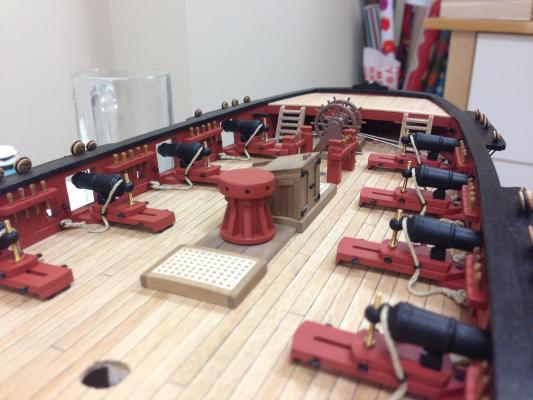
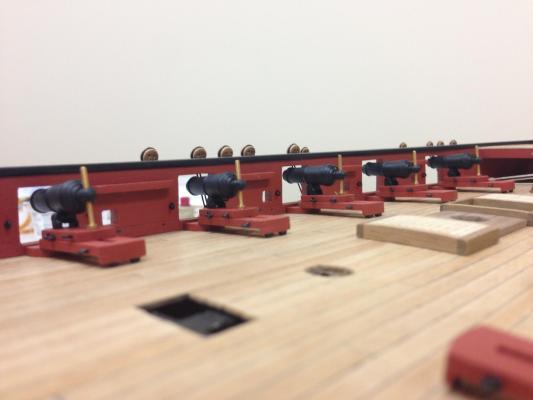
Little bit of progress on carronades, prob won't post more until I've made some progress on slide tackles. Planking under capstan is made from walnut strips rather than the ply part supplied. Mizzen pinrails still need a fair amount of tidying up and not fixed. Not much deck space left at the stern!

- Dubz, Blue Ensign, ccoyle and 8 others
-
 11
11
-
Pete, Jim - just muddling through trying to find things that work for me...
Stergios - take a look here http://modelshipworld.com/index.php?/topic/509-hms-snake-by-beef-wellington-caldercraft-scale-1-64-first-wooden-ship-build/?p=76645. Once rigged, carriages will be glued to the sliding bed so its secure on model. These are unglued while being rigged and the pin seems to hold them in position as needed together with the small piece of wood holding it in correct place.
-
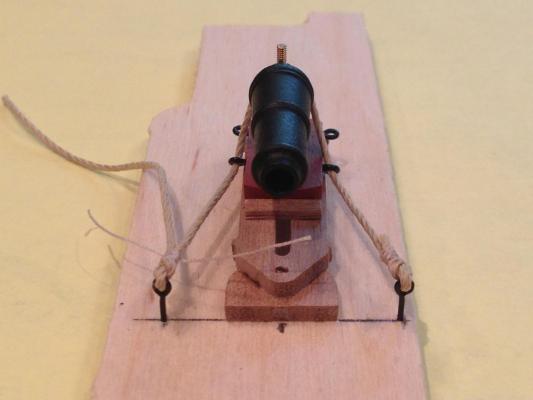
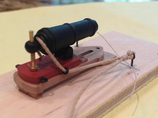
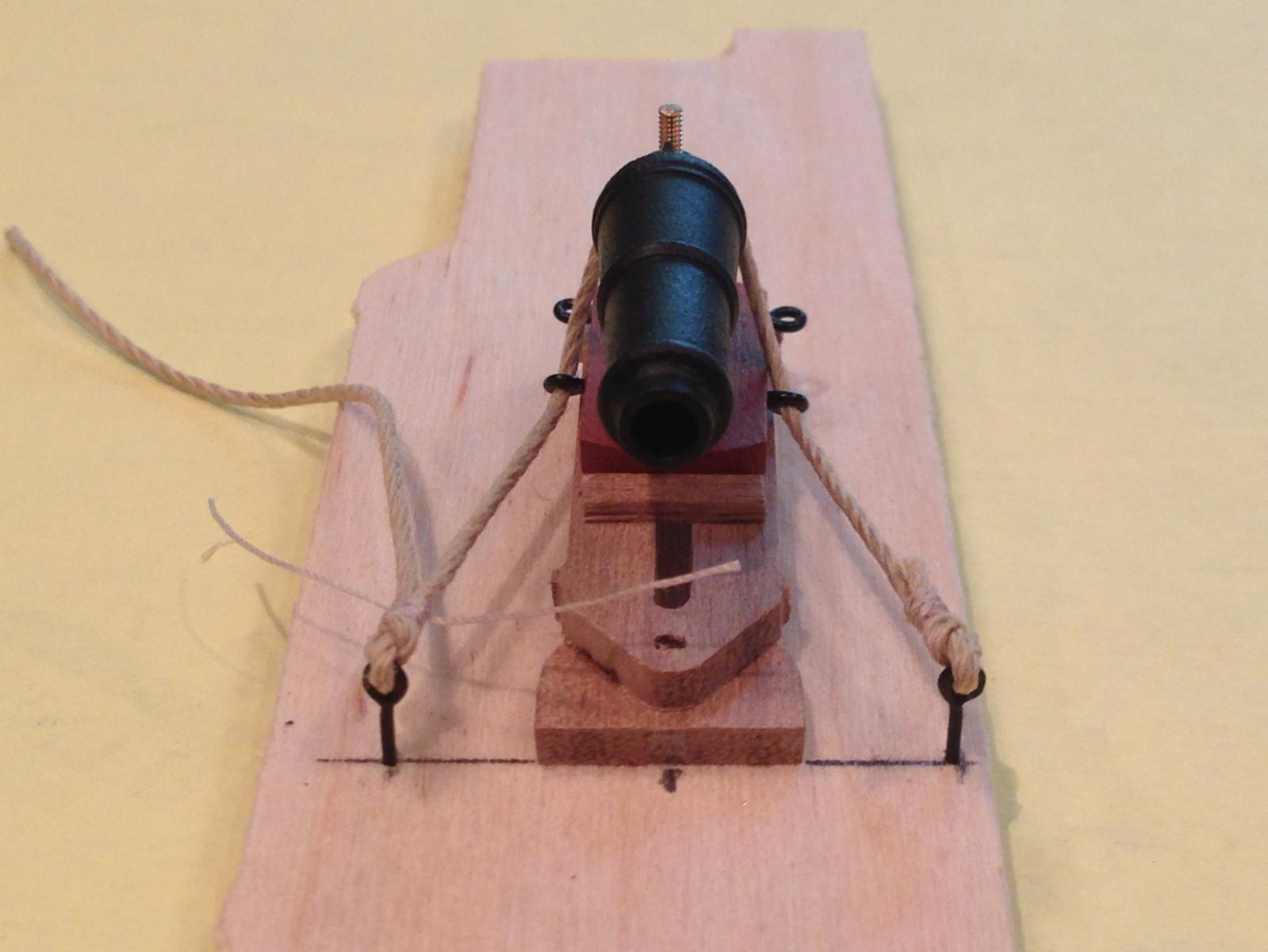
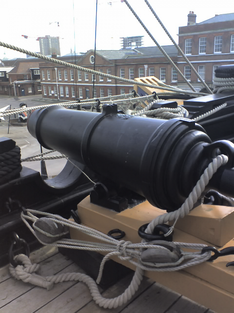
A little bit of info on the technique I'm using on the breech rope, I'm using the Victory carronade photo below as reference.
1) One end of the breech rope is knotted to eyebolt and seized (I believe a 'half-hitch'). 1.0mm Amati line was used for breech rope (purchased separately) and 0.1mm Caldercraft line was used for the seizing. Used the Amati line because the supplied 1.0mm line just did not look good (flat and loosely wound). The seizing looks a bit overscale in the photos but I'm happy with how it looks in person. Dilute PVA was used to secure before trimming.
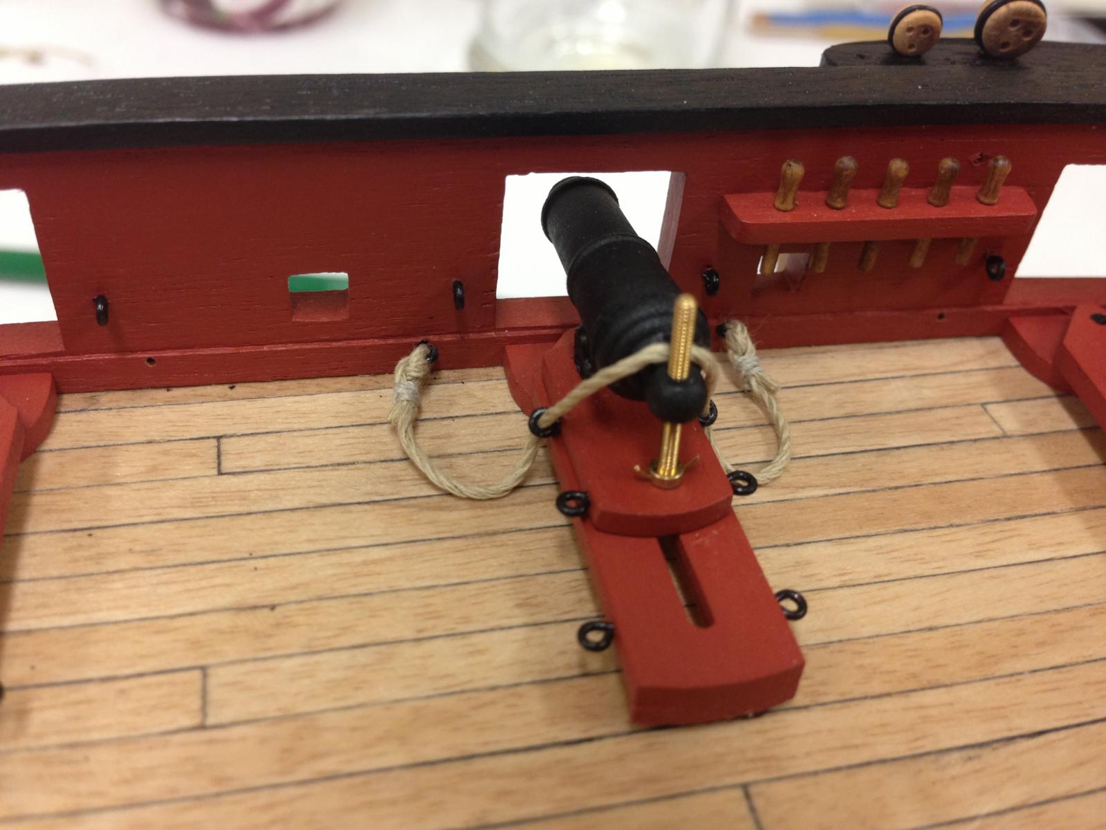
2) Threaded the unfinished end through the various ring bolts.
3) Used a spare bed as a jig and drilled holes in same place as on the ship to get correct length at 'fully recoiled' position. Note why I had spares' below.
4) Knoted and seized the unfinished end and its ready for installation. Photos below show ends both finished and untrimmed
The height of the elevation screws has also been reduced as these seemed to be too high as supplied. This needed to be done after installation as screw thread gets ruined.
Other side note for those considering the aftermarket CC carronades. I encountered some problems with the screw thread not being drilled correctly which resulted in a stripped elevation screw. Only solution was to buy replacement barrels/screws. Next problem was the supplied barrels were missing the screws, so had to buy yet another replacement as it was pretty hard to determine who was at fault. (These were purchased through Cornwall Model boats as there is no US supplier which means high shipping costs for trivial items)

-
I've seen a number of builders using "GS-Hypo" cement when it comes to some aspects of rigging but I must confess to being clueless on the benefits of this type of glue. I've also see concern that CA glue can damage hemp based line, but how does this manifest? Is it really just down to user preference or are there real no-no's with either glues?
Appreciate any practical experience people would care to share.
-
Got a question regarding the main mast and hopefully someone can help.
The plans show that the platform that is attached to the main mast is attached perpendicular to the mast. However, as the main mast is raked back a few degrees, this means that the platform will not be parallel to water level. What is the correct orientation? Parallel to water level or perpendicular to the mast?
Jim, I always thought that the platforms should be parallel to the waterline, and that's what I see in various AOTS plans, not perpendicular to the mast. However, the Snake plans clearly show these being perpendicular! I more inclined to believe the AOTS plans vs the supplied instructions given other errors/inconsistencies noted to date.
I'm sure that one of the other more experience builders can state definitively.
-
Fantastic work, Jason!
What;s the need of the sliding bed posterior eyelets you have fixed?
Thanks
Thanks Stergios - Those would be for the training tackles, I'm not going to rig those however, they would also need a set of eyebolts in the bulwark as well which again I'm not going to attach - although it could look good, it could make the the whole deck a bit too cluttered. The aftermarket carronade supports are definitely longer as you've probably seen and take up more deck space that those supplied. If you haven't seen it already, you should check the photo at link below, Len's carronades are definitely something to aspire to and show the full rigging. http://modelshipworld.com/index.php?/topic/2107-hms-bellerophon-by-len-semi-scratchbuilt-victory-models-kit/?p=83285
-
Wow Jim, you really have been busy! Looking fantastic, you've covered so much ground. How did you shape the top of the masts with the square section?
-
CaptCraig, Ferit, Mort, Sjors and BE - thanks gents for the continuing support.
Some slow but steady progress, finally getting a chance to try the various different things that I've thinking about for the last month or more:
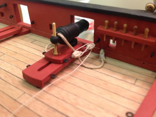
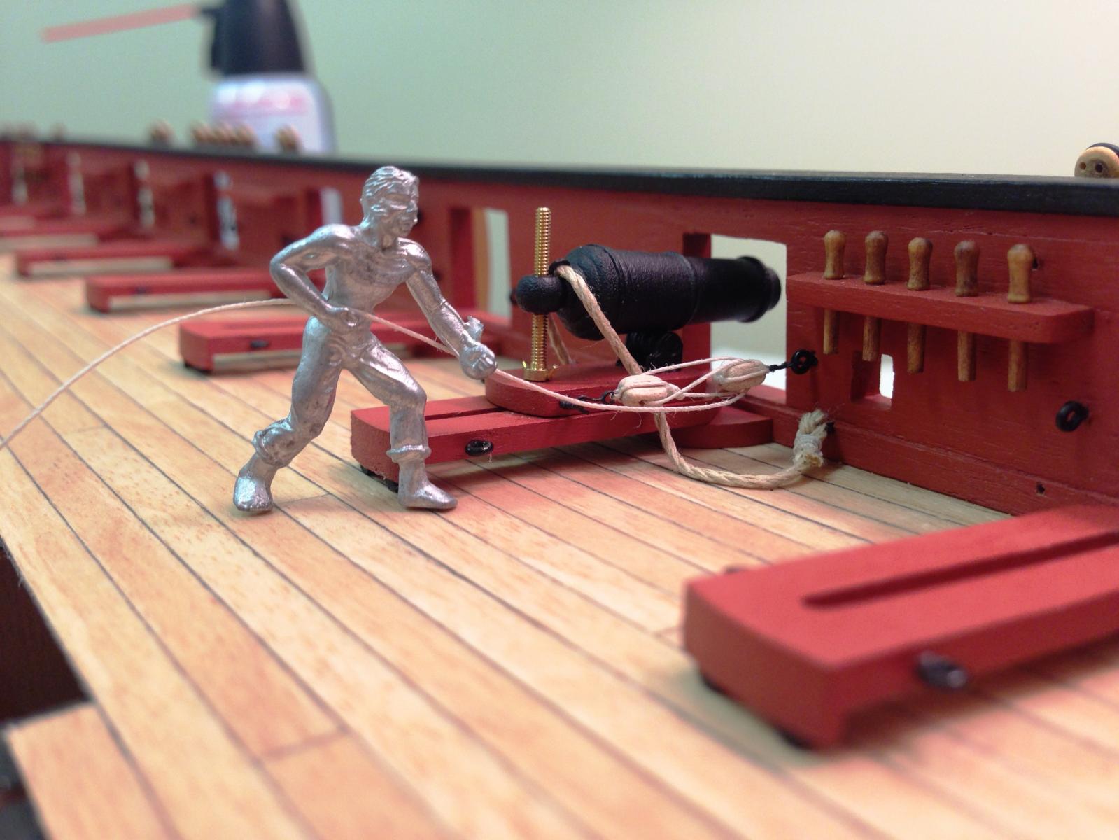
Have one carronade attached with breech rope. Unfortunately my seized knot ended up looking more like a baguette than a knot after all the manhandling, hopefully this will get a little easier with practice. I'll probably play with this some more to get final placement so it looks natural.
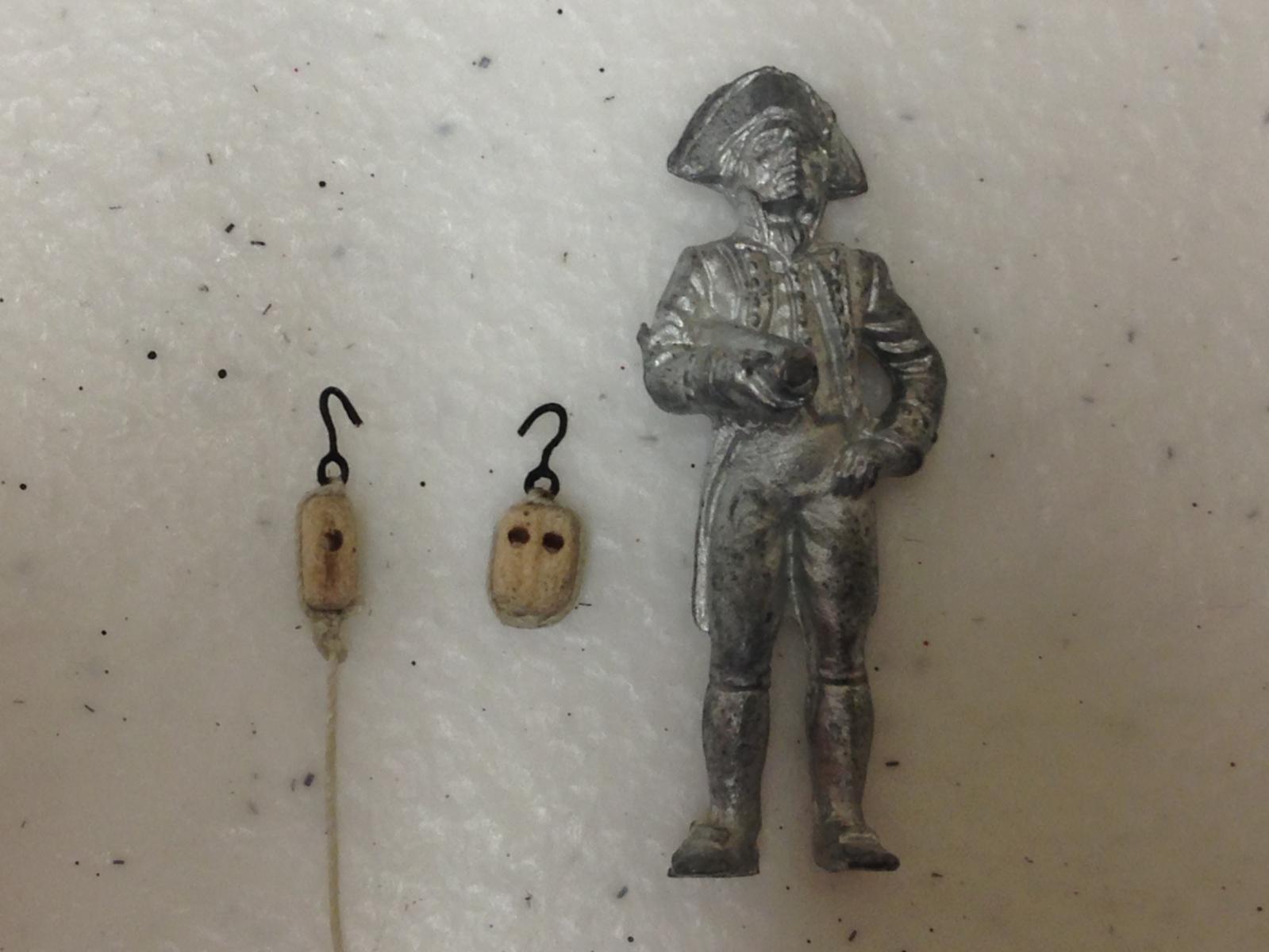
Made up a couple of hooks and attached to a double and single 3mm block to see how this would look. Hooks are made from the small 0.3mm brass etch eyebolts bent to shape. Once rigged, managed to get one of the crew to test things out - thumbs up. Pretty happy with the way my first carronade is shaping up.
I'm probably going to frap the tackle falls around the blocks as per current practice on HMS Victory rather than cheese them on the deck - no Admirals inspection for me...
As always, suggestions welcome.


- dafi, Kevin, freewheelinguy and 6 others
-
9
-
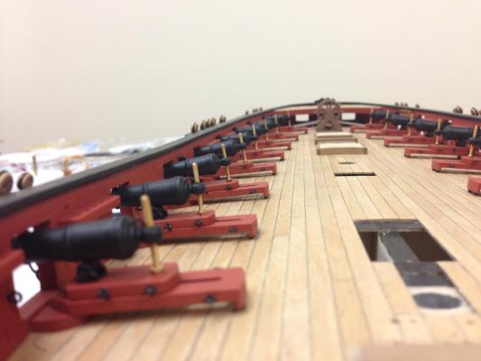
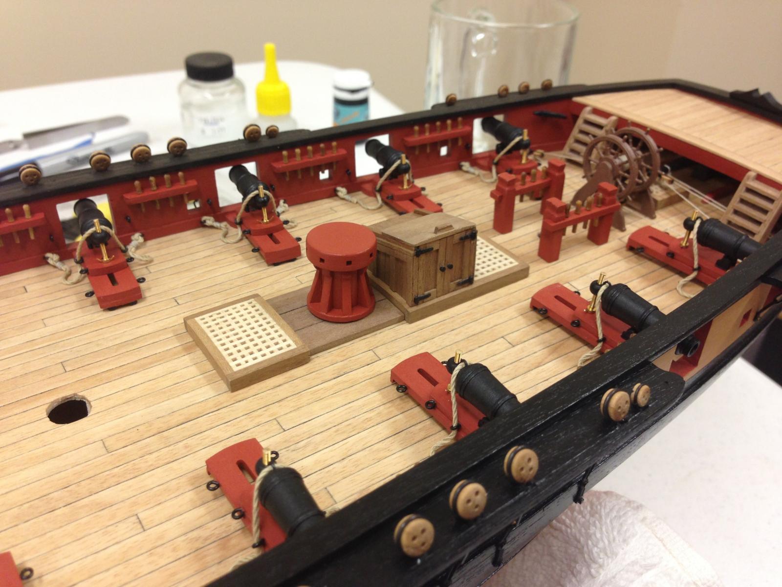
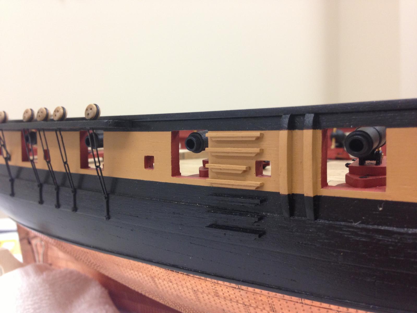
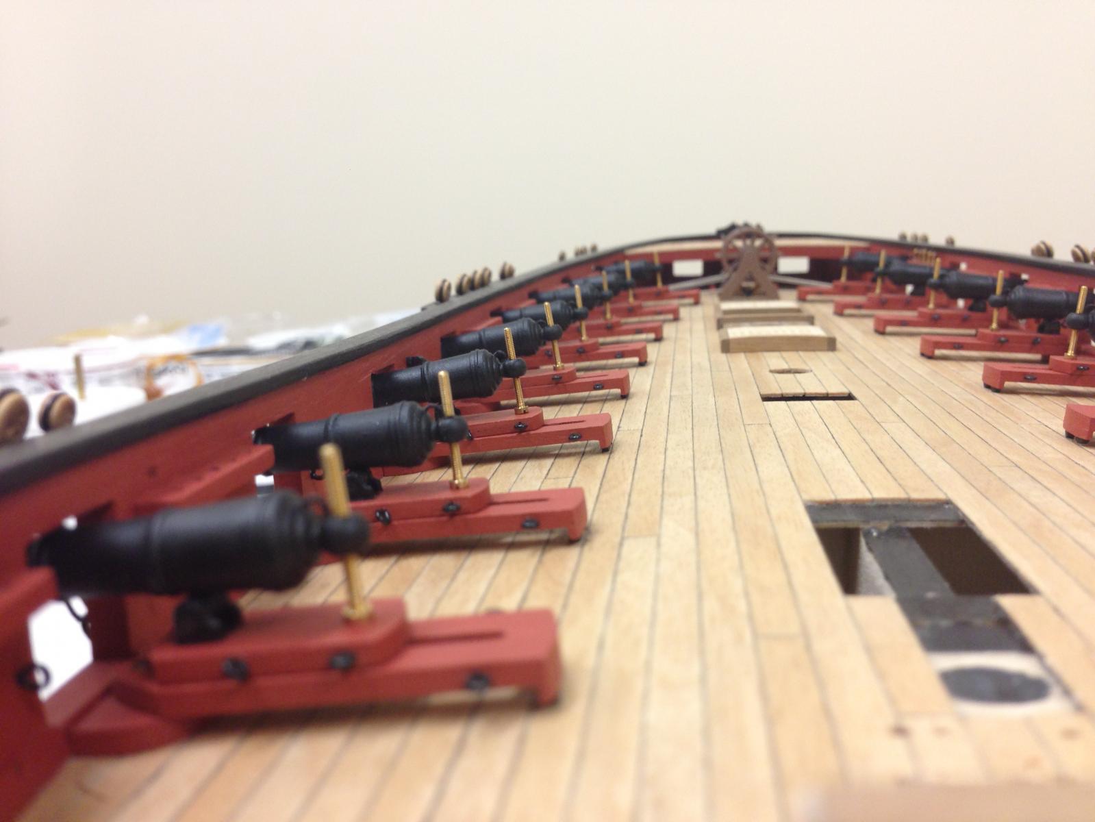
Feels like a long time since I've made a post. With a bit of focused effort all 16 carronades are ready for final assembly (last cannon is getting close), I'm taking maybe a rather convoluted approach but hoping it will work OK. The pedestals are all attached to the deck, but I'm leaving the slides unattached for now so I can rig the breaching ropes off the ship. It also give me a chance to align the elevations individually using the small elevation screws before attaching the turning handles. I'm not sure of the correct elevation for these, but think it would make most practical sense to have a small gap at the top of the gunport as I've tried to achieve.
I'll leave off the deck fittings until everything is rigged to hopefully make this task as easy as possible. Think I'm finally homing in on the approach to the rigging which I suspect will be the next never-ending task, but hope not.

-
Another idea that I saw in the CC Victory instructions downloaded from the Caldercraft site (I find the online instructions very helpful because the newer instructions seem to cover a lot more generic 'basic' stuff than the very sparse ones provided in older kits). Anyway, in there sheaves are added by making a sandwich of wood strips and pulley and then attaching to the end of the cathead. Looks like a clever idea.
-
Hi Stergios, I'd that I had initially wanted to blacken all the parts. However I reached the conclusion that it was probably not worth it. There are so many brass parts that I couldn't get to look the same colour (some I could only get to be brown, I'm guessing each part is a slightly different alloy)) so I turned to painting which I think is easier and still can give a nice look. Another consideration is that using CA glue to attach everything together that would also be very hard to do to get things looking consistent. I was glad I tried though.
-
Richard, your boats look great. Its funny, I had exactly the same experience even after sanding the hull. I've ordered some styrene to do what the paper should because I was also thinking the paper may not have enough body to simulate the frames. You made a very nice job of it however and I'm reconsidering my approach, I'm curious what your thoughts are on the merits either way.
-
Looks lovely Jim, I'm trying to get some more time back in the shipyard after returning from our holiday (actually we were in your neck of the woods near Bath), unfortunately we had some water in our basement so the shipyard has been out of commission. Must be nice to have all the deck fitted out.
-
-
-
Hi Len, everyone has already said it, carronades look fantastic. Is the breeching rope the beige 1mm Amati line?
-
I'm glad to see you and your Bellerophon back, I'm very much enjoying following your progress once again. I love the "Art brings cheese" saying, you should have a lot of cheese!

-
-
I like the look of the wood as well Mobbsie, have you thought about painting the photetch parts in the same/similar colour to the wood? That could be an interesting effect. Looking very nice in any event.
-
i am not painting the straps black, it seams to make it all to much (in yr face) i will let it tarnish with the rest of the plates
Looks great Kevin, you can probably rest easy because the straps would not have been black but some sort of cuprous alloy. I'll be interested to see how the photo etch material ages compared to the copper.
-
This will probably be my last update for a while, we leave next weekend for a family trip back home to the UK, its been 5yrs since I've been home and seen my sisters side of the family so should be fun.
I've been spending so much time on the canons/carronades and other deck fittings that I needed a complete change of pace so decided to start tackling the bowsprit. This proved to be pretty enjoyable but had its share of 'challenge' The instructions are not overly helpful, and in some cases misleading...at least to me. Sorry for the wordy update but think this may be useful to others.
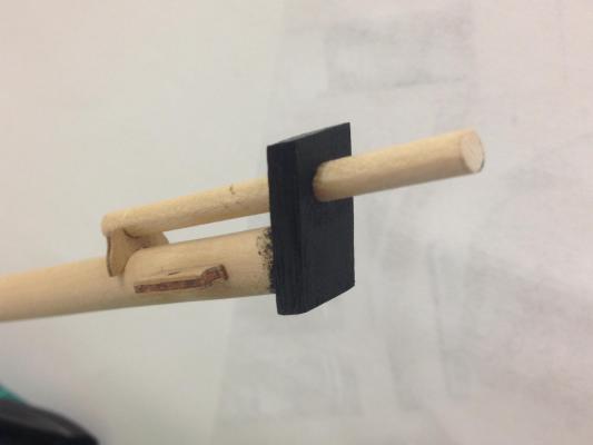
First off I cut the bowsprit dowel to length and shaped the end that will sit on the deck. Its important to understand how the bits will be positioned as this anchors one end. This has to be balanced with ensuring that the angle of the bowsprit is correct, and I judged this by measuring he clearance above the highest part of the bow. Once all that was done, I measured the length of the bowsprit from the end of the bow to match the plans. Comparing this to the plans showed that the total length of my bowsprit is about 1.5cm longer than the plan, but should match the plans once installed. I suspect other's results will be a little different given the variances in each build.
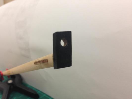
Next I cut the angle onto the end of the bowsprit to take the cap and started shaping the cap. The holes in the cap are round and the instructions/plan give no insight into how to do this other than 'form a tenon'. I made it round because the hole in the cap is round, which was a mistake. Basically there is no way that the hole in the cap can be angled so this fits neatly with no gap. Looking at some reference material ("Rigging Period Ship Models") I saw that the tenon should be square. To try to correct this I rebated a section and glued in some scrap wood to simulate the square tenon.
Next issue was with the top hole for the flying jib. The hole is cut with 4mm diameter at 90deg to the cap, the flying jib is 4mm diameter and needs to sit at the same angle as the bowsprit Basically there is no way the hole can be angled without requiring some element of filling which I did with some scrap.
Results are in photo below. Another error instructions (I believe) is that they indicate that the cap should be at 90 degrees to the keel, and as the keel is quite angled on the Snake this seemed odd, and is contradictory to the plans which the show the cap 90 degrees to the waterline. I went with the plan.
Touch of paint to see how everything ended up....realized that all the work to get the square tenon correct was barely visible once painted.
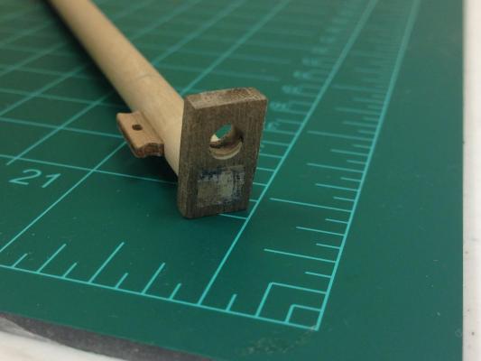
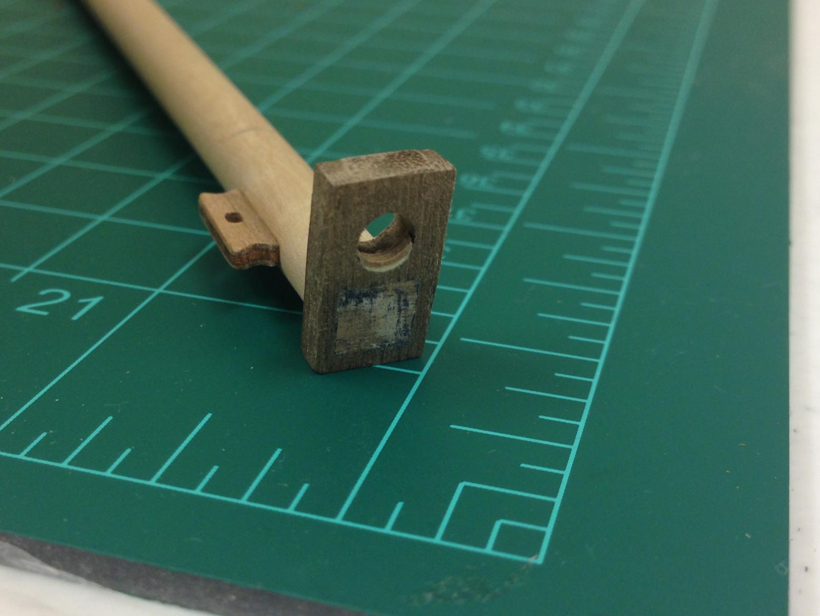
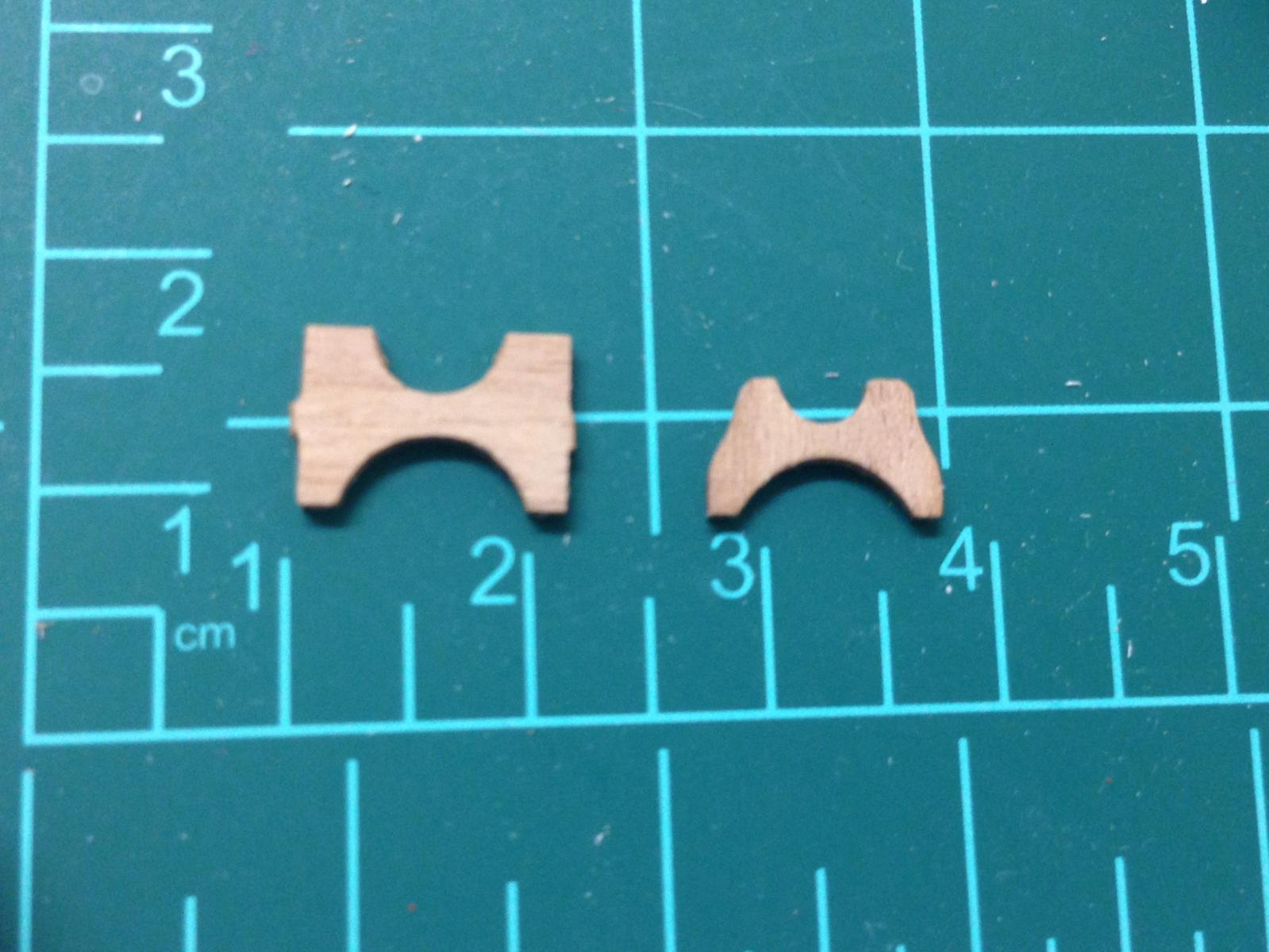
Next came figuring out the jib boom saddle. The supplied piece (left) was dimensionally out in a number of places, so I ended up making my own (right) which I was much happier with
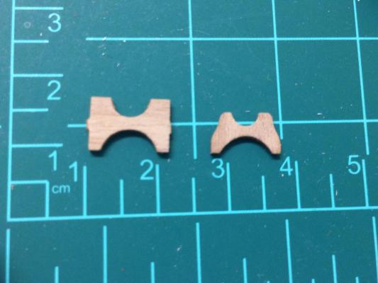
Dryfitted for now, but the 4mm dowel sample shows how everything will fit eventually.
- hamilton, 4whelr and mort stoll
-
3
-
That's a wonderful base B.E., amazing what you've achieved. Seems a shame to hide the wonderful paintwork but a small price to pay. These ships seem to take on a whole new persona when displayed like this and you've really done her proud.


HMS Snake by Beef Wellington - FINISHED - Caldercraft - Scale 1: 64 - First wooden ship build
in - Kit build logs for subjects built from 1751 - 1800
Posted
Thanks for the kind words gents, means a lot coming from you.
Stergios - I blackened the hooks first, and then painted before bending. However, what I've found works better is to just blacken the hooks and paint afterwards. Otherwise the paint comes off very easily and needs another coat.