

KenW
-
Posts
1,202 -
Joined
-
Last visited
Reputation Activity
-

 KenW got a reaction from mtaylor in Mary of Norfolk 1790 by KenW - Pilot Boat
Thanks Adam.
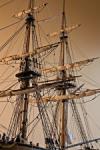
Another photo:
-
KenW got a reaction from mtaylor in Mary of Norfolk 1790 by KenW - Pilot Boat
Well, everything is done except for the little sea men I created with the help of Amazing Models by Snapdragon. The guy whom I worked with was excellent. And although the price was high, I'm happy with an early birthday present.
Watch this space.
-
 KenW reacted to Chuck in Sloop Speedwell 1752 by Chuck - Ketch Rigged Sloop - POF - prototype build
My daughter was very complimentary about my latest model. But she said I had to put something on the table. It looked too bare and boring. So not wanting to disappoint my lovely daughter I added some laser cut books. Yes that is a very very tiny Seawatch book about Speedwell Volume 1 I believe. Great reading while at sail on those quiet evenings!!
The cupola really isnt that shiny....its just the very bright overhead light and the photo camera lights. It is actually much darker and subdued. I think. LOL.
The books are just 1/4" tall so very very very tiny. Cleaned up after laser cutting and ready for a printed cover scaled down....But here you see them in the raw state. These are right off the laser cutter and just sanded to remove the char. The close ups are brutal but they look really good at regular viewing. About the size of your fingernail.
-
KenW reacted to Chuck in Sloop Speedwell 1752 by Chuck - Ketch Rigged Sloop - POF - prototype build
Greg convinced me!!! I also spent a great deal of time looking at the contemporary model. I also decided to coper the top of the doorway. It just made sense to do that. I painted a plain piece of paper with the copper paint and cut a narrow strip. This allowed me to leave a nice neat edge on the front of the bulkhead. I left just a 1/64" of the top showing so it looks like molding around the doorway. I am sure I will get used it over time.
-
KenW reacted to HAIIAPHNK in Carving from Belgorod
After working on the top of the head there were some minor refinements and modifications. The largest of the interventions concerned the face of my Chewbacca. The carving of the face as a separate segment on the table, detached from the rest of the sculpture required correction. Not everything could be seen, and there was a fear of cutting off too much. And in the end the face turned out a bit flat. I wanted to add more gradients. Just a little bit. I left that question out on purpose. I was waiting until I could examine the whole figure. And now I waited for that moment.
I didn't take many intermediate photos. I took only the starting one, and then woke up when everything was already finished. It all happened so fast.
And there's a paradox. You can't tell the difference from the finished photos. It's as if I hadn't redone anything. But there is a difference. I "sunk" deeper lower eyelids, thus changing the vertical slope of the eyes, similar actions touched the cheekbones. And the rest of the small touches. It seems that in total the changes are not noticeable, but now my soul finally got what it wanted.
What's more noticeable is that now I've cleaned up the whole figure. And the fresh color looks completely different. You can also see in the last photos that the sculpture has become shiny, as if I polished it or rubbed it with oil. In this case I didn't even add a drop of oil. Since the work is not finished yet, oil can do some damage. The lion is assembled from segments that are held together with glue.
And there were already moments when we had to take the sculpture apart and glue it back together again. What if I have to take it apart again? Then the oiled wood could already be in trouble. So I didn't use oil. And I wasn't going to polish it to a high gloss on purpose. That's another difference with this kind of wood. It gets shiny very easily. This effect has been seen before, and then simple contact with a glove polished the surface in the same way. Now you can see the same effect, but without the darkening.
-
KenW got a reaction from mtaylor in Mary of Norfolk 1790 by KenW - Pilot Boat
Thanks Gary.
I see you've been busy. Just looked at your current build and find I have a lot of reading to do.
I know your build will be a masterpiece since I know your modeling abilities.
Cheers.
-
 KenW got a reaction from GrandpaPhil in Mary of Norfolk 1790 by KenW - Pilot Boat
Thanks Adam.
Another photo:
-
KenW got a reaction from GrandpaPhil in Mary of Norfolk 1790 by KenW - Pilot Boat
Well, everything is done except for the little sea men I created with the help of Amazing Models by Snapdragon. The guy whom I worked with was excellent. And although the price was high, I'm happy with an early birthday present.
Watch this space.
-
KenW got a reaction from GrandpaPhil in Mary of Norfolk 1790 by KenW - Pilot Boat
I’ve set the jib sail and completed all the rigging. There just remains tying off and gluing the lines at their cleats and adding some coils. I also need to raise the flag.
-
KenW got a reaction from GrandpaPhil in Mary of Norfolk 1790 by KenW - Pilot Boat
The mainsail and foresail have been rigged to the boat. I’m having problems getting the sails to flare out from the hull so it looks like it's sailing in the wind. Of course, there is no wind. Therefore there is no force pushing the sails out and when I tighten the sheets, the lines keep pulling the sails closer to the boat. And the sheets never look tight, always loose. Not the look I want.
Also the stove and some jars have been added to the forward locker. There is a small jar heating water for tea.
-
KenW reacted to FriedClams in Pelican 1943 by FriedClams - 1:48 - Eastern-Rig Dragger
Greetings fellow modelers. Thank you for your comments and likes!
Here's a short update. The hull has been cut away from the station form extensions using a 1.25” diameter circular saw chucked into a Dremel rotary tool. This is a somewhat dicey procedure because the rotating blade is just looking for an excuse to hop from the cut and remove a chunk of sheer strake instead. But a strong grip on the tool keeps a pinched blade from jumping and makes quick work of the task at hand. However, I do not recommend this method to sensible modelers.
Even though the hull planks were edge glued to each other, I decided to add reinforcing card strips between the station forms, which I glued into place with breathtaking amounts of CA. Finally, I “painted” the entire interior with a 50/50 water/PVA solution to resist warping caused by humidity swings.
In the previous post I pointed out a few hull planks that were recessed - not flush with the adjacent planks. I used wood shavings to build them up and then sanded them back.
Also, I removed material from the lower hull planks at the keel and stern post. These planks previously stood proud and are now flush. A shout-out to John, Andy and Håkan for clearing this matter up for me. Being primarily a model builder with a secondary interest in boats/ships, my understanding of boat construction at the nuts-and-bolts level on anything larger than an open boat is a bit sketchy. The knowledge base and ready willingness of MSW members to help, inform and encourage has made every model that I've built on this forum better and more accurate because of that input. Thank you!
More hull filing/sanding and cleaning up is still needed. And I've done nothing yet to finish the backbone assembly.
Thanks for stopping by.
Be safe and stay well.
Gary
-
KenW reacted to Chuck in Sloop Speedwell 1752 by Chuck - Ketch Rigged Sloop - POF - prototype build
Here are two photos of the second version which I made. This one is finished with copper paint and sprayed with dull coat. The copper paint was just from one of those copper leafing pens. It worked really well actually. This was my best result with the copper attempts. I havent glued the cupola on yet so I can keep trying both and pick the one I like best.
-
KenW reacted to Chuck in Sloop Speedwell 1752 by Chuck - Ketch Rigged Sloop - POF - prototype build
The cupola...
I was undecided if it made sense to add the cupola now or wait until after the deck is planked. But I decided it might be easier to plank around it so I went and completed it.
It will be shaped in a sort of lift method.
Below you see all the parts needed laser cut along with the first prototype completed.
Step 1...glue the 3 layers of curved roof together with the thinnest curved horseshoe at the end as shown.
Step 2...
Glue the 1/16 piece on the bottom which will give you the ultimate rounded shape you are shooting for.
Step 3...
Sand the roof at first to that rounded shape along the sides. Use the piece glued to the bottom as a guide.
Step 4...
Then sand the top to shape. Specifically the back end of the dome to establish a nice curve. Dont over sand the forward side. Just remove the char and you will be good.
Step 5...
Finish off what remains by sanding the remaining parts to a nice dome shape. It should look like the bottom of a test tube cut in half. Now at this stage you could also take a Dremel with a small sanding tip and shape the inside. But why bother. It will never be seen. You can make it as thin as an eggshell if you desire but seriously there is no point. You should remove the cross piece from the opening on the forward side though. There is no reason to keep that now that it is all shaped. That was from the 1/16" layer that you glued to the bottom of the assembly early on.
Step 6...Take the last remaining laser cut horse shoe piece (1/8" thick) and sand the char from the outside edge. Also round of the top outside edge. When you place the cupola on top it should leave a consistent lip all around it. This gives you the illusion of a molding piece all around the bottom of the cupola.
Step 7...Paint it copper or brown or whatever color you prefer. I didnt want to go with shiny metallic copper paint. I opted for a medium brown color.
But before you can add it to the model the framing for the cupola needs to be added between the deck beams. That is the last laser cut piece. Just sand the char from it and position it as shown. No need to clean the char from the center because you will never see it. center it behind the door.
Step 8...
Glue the cupola in position after making sure it fits snug against the door frame. It should also leave a little lip around the top of the door frame being slightly smaller in size. For now I have left the rim around the top of the door frame bright. But I may decide to paint it the same brown color to match the cupola later on. I havent decided yet. I want to wait until after a build the railing and have the deck planking all done. I will see how it all looks at that time.
This finishes work on the qdeck for now....I am going to finally move to the fcastle area.
-
 KenW got a reaction from ccoyle in Rattlesnake by KenW - FINISHED - Model Shipways - Scale 1:64 - American Privateer
The model is finished! I made an ensign which I’m flying from the gaff. I followed Chuck Passaro’s method from his log about his new kit of the Queen Anne Barge which can be found at ‘https://modelshipworld.com/index.php?/topic/12476-syren-ship-model-company-news-and-forthcoming-new-projects-products/&page=9’. His method worked and I’m really pleased with the flag.
A few words about American ensigns during the Revolutionary War: According to the US Navy ‘American Navel Flags of the Revolution’ web site, the Continental Congress in 1777 ”passed an act establishing a national flag for the United States of America. The law specified the flag have thirteen stripes and a blue ‘cannon’ of thirteen stars. No further details were specified.” This lead to several variants of navel ensigns, the most famous being John Paul Jones’ ensign with red, blue and white stripes and eight pointed stars. For my last model I decided to use the ensign flown by John Barry on the US Alliance which had 7 white stripes, 6 red stripes and eight pointed stars. For the Rattlesnake I’m using a “common variant” of 7 white stripes, 6 red stripes and five pointed stars arranged in a unique pattern. I guess I like being different. But I am the captain.
(Notice that I neglected to trim some lose threads attaching the ensign block to the gaff.)
More Photos:
-
KenW reacted to FriedClams in Pelican 1943 by FriedClams - 1:48 - Eastern-Rig Dragger
Greetings fellow modelers,
It's been said that the problem with doing nothing is you never know when you're done. I'm not the best version of myself when I am doing nothing, so it's well past time to get back to work on this model. After seven months I finally have some progress to share, but first I'd like to note the donation of one of my earlier scratch builds to the Jonesport Historical Society in Maine this past summer.
The model is the sardine carrier William Underwood. This vessel, considered state-of-the-art when built in 1940, worked for decades out of Jonesport shuttling millions of pounds of fish to the Underwood cannery located there. The sardine industry in Maine was no small affair and lasted over a hundred years from the 1870s to the closing of the last cannery in 2010. At its height in the 1950s the industry employed some 8,000 people in many dozens of canneries up and down the coast and particularly in the region known as Downeast. Sardine carriers were not fishing vessels, but rather they were boats that gathered up sardine herring from the vast number of weirs and seines stationed along the coast and transported those fish back to the canneries. These carriers were numerous and ubiquitous during this period, but today only a handful remain mostly as yacht conversions. Indeed, the William Underwood now floats as a personal pleasure craft. Oh – and if the name Underwood sounds familiar, think deviled ham and chicken spread.
The Jonesport Historical Society is a small organization, run by enthusiastic volunteers. I was surprised to learn they didn't have a sardine carrier model in their collection especially considering the importance of Underwood Canning in the town's history. The carriers and the canneries are long gone but the history remains. The society museum doesn't see a large number of visitors, but if only 50 people view the model each year, that's still 49 more than would have seen it collecting dust on my shelf. The society was happy to receive it, but the satisfaction was all mine in giving it to them.
It's a POB scratch built in 1:48 and approximately 18”(46cm) long. Finished in 2018, it was my first scratch boat model that wasn't an open boat.
Hull Planking
The Pelican is an Eastern-rig fishing vessel. If you're unfamiliar with this type of boat and interested in knowing a bit more, there's a brief explanation of its evolution in the intro post.
I left off on this build with the stations in place and the backbone resting on top but not attached. After working on it in irregular bursts of activity over the past month, the hull is now completely planked. I don't have any incremental progress photos to share but here's a few images and where the model stands today.
In the image below, the backbone is set and the garboard is placed. The slots in the bulkheads were intentionally cut deeper than required to allow for vertical adjustment if needed. It's more important that the distances from keel bottom to shear are correct than having the backbone bottom out in the slot. Happily, the rabbets I had pre-cut were at the proper height and the garboards fit into them quite well. The stations forms were cut from 1/8”(3mm) plywood and the planking material is basswood. At 070”(1.8mm) the planks are a tad thicker than I've used in the past. I did this in hopes of gaining a smooth fair arc across the station forms.
This is a round stern boat, so I added a curved piece of wood aft as a landing spot for the planking.
I attached the sheer strakes which at midships scale to approximately 10” in width. I then measured the distance between the garboard and the sheer strake at each station and divided it into four belts. The boat had 24 strakes per side including the sheer and garboard, so I ended up with two belts of five and two of six. I developed all the tick strips in CAD and printed them out. I've never had much luck in accurately pencil marking the plank spacing on the stations, so instead I pin the center of the strip to the station to keep it from moving, then pin punch the remaining plank edge locations. Obviously, it doesn't matter where the pin punches fore and aft on the station, only up and down.
I previously marked the landing spots for the plank ends at the stem on one side of the boat only. After that side was completely planked, I transferred those plank edges to the opposite side of the stem using the little sled jig below. Looking directly at the bow from the front, I want the planking on both sides of the stem to line up. If the plank landings are a little irregular on side “A” I still want side “B” to match it.
The thin saw cut across the sled was when I thought I would use a scalpel to mark the opposite side. I decided against that idea and made a second wider cut that would accommodate the width of a mechanical pencil lead.
As you all know, every hull plank is tapered. To help in this repetitive process I created the little plank holder below. It's just two strips of wood with an end stop glued to a scrap of plywood.
Below it is loaded with a plank strip standing on edge.
In years past I would taper planks with a straight edge and scalpel which I found to be a mind numbing and soul crushing activity. I now use this miniature block plane from Veritas.
Sharp as all get out and no chattering. Around $47 U.S. and worth every penny from Lee Valley Tools in Canada. And yes, it is small.
The only problem with Lee Valley is in finding other items I didn't realize I needed so badly.
For bending, twisting and otherwise torturing the planks I used this small heating iron that is designed for quilt makers and in fact belongs to my wife. Manufactured by Clover, it has two sizes of heat plates and three temperature settings. The mid setting is just about right, but being a modeling Neanderthal, I use the high setting which if left more than a few seconds will burn the wood. I prefer this iron over a clothes travel iron because I often use it directly on the hull. It's small size and light weight make it easy to use and work with as long as you don't brand your forearm with it. I'll take a prepared tapered plank and glue one end down on the model then apply heat to it as I work my way along the length of the hull. Hold it in position until it cools then glue it down.
The hull has been roughly sanded to see what else needs done before cutting it from the forms. The image below provides a good example of the sort of thing I'm looking to find. At the stem, the third and fifth plank up from the sheer line are slightly recessed. There is enough plank thickness to where I could file down the adjacent planks flush with those two, but that's working down to the lowest common denominator. Instead, I'll use my handy dandy block plane and strip a curl of wood from a piece of scrap and build up the offending planks, then sand them flush.
The garboard and lower planking appear to be sitting on the surface of the keel/stern post in the photo below. But what is actually seen is one third of the plank thickness and the rest of the plank is sitting down in the rabbet. Should the ends of these planks be flush at the stern post or stand slightly proud? Chamfered into it? After looking at many real boat photos, I'm still not sure.
Also, in the photo you can see evidence of my wood burning skills.
Next comes cutting the hull from the forms, sealing and reinforcing the planking between stations on the inside and finish filing/sanding the exterior.
Thanks for stopping by.
Be safe and stay well.
Gary
-
KenW reacted to FriedClams in Pelican 1943 by FriedClams - 1:48 - Eastern-Rig Dragger
Greetings,
Here's the current state of the model.
The backbone drawing template was printed out in three sections onto full sheet label paper. The wood for the backbone is poplar and was cut to the required thickness using my full sized table saw. The templates were affixed to the poplar and cut out with a scroll saw.
The rabbet was then carved into both sides.
Below, the backbone is sitting temporarily on the station forms, waiting to be permanently attached.
This model is being placed on temporary hold and it will be some time before I post again. I thank all of you for your interest in it and I hope to report some progress by the end of the year.
Thanks. Stay well.
Gary
-
KenW reacted to FriedClams in Pelican 1943 by FriedClams - 1:48 - Eastern-Rig Dragger
Greetings all and thanks for the kind comments and the "likes".
Before moving on to the backbone, the station curves on the body plan need to be completed and developed into station bulkhead form patterns, printed, cut from plywood and finally arranged on a building baseboard.
The model will be displayed with the fish hatches open and probably a bunker plate removed to allow a peek into the dimly lit partitioned hold below. The positioning and spacing of the stations as indicated on the original plans are provided only to define the shape of the hull and of course, do not reference any structural element. But because I'm using those stations as bulkhead locations, where they land within the fish hold area is of consequence. As luck would have it, station # 5 intersects the forward hatch and #6 lands on a coaming timber at the aft hatch. So those stations needed to be removed and three new modified stations added in replacement. In the drawing below, the vertical red lines are the removed stations #5 and 6. The blue lines are the replacement stations 4A, 5A and 6A, which as you can see do not interfere with the hatch openings and will provide a landing spot for the hold outer wall planking.
Body plan curves for three new stations were generated from the "lines" drawing in the same way station #1.5 was done in my previous post.
Stations #5 and 6 were removed from the body plan and 4A, 5A and 6A were added.
The added station forms were hollowed out to the width determined by the hull framing at each cross section. Deck beams will eventually strengthen these openings and be installed after the form extensions are cut from the hull and the fish hold is planked and partitioned.
The remainder of the station bulkhead forms were then drawn up. Each one has a drill hole mark and separation cut line that will allow the forms to be detached from their extensions once the hull is fully planked. One end of the scroll saw blade will be inserted through the drilled-out hole and used to cut along the separation line. A Dremel rotary saw will be used to make the final separation.
I printed the forms on full sheet adhesive labels and affixed them to two 12” x 24” sheets of 1/8” craft plywood taking advantage of the factory cut edge.
Scroll sawed, filed and sanded.
Attached to the baseboard.
Next came the backbone drawings. The original plans show very detailed dimensioning describing the shape of these timbers, so it was mostly just an exercise of re-plotting this data onto a newly created grid. Rather than tracing an imported CAD image, I took this extra step because I already knew the original photocopies were slightly skewed and the import process would have only exaggerated the problem.
Here's how the backbone will sit on the station forms shown in profile.
Before I physically cut and assemble the backbone, I'll make a cardboard mock-up and test fit it to the forms. It would be beyond irritating to say nothing of embarrassing to spend hours carefully making a backbone that doesn't quite fit because I botched the drawing.
I look forward to the end of this preliminary work and to begin actually building the model.
Be safe and stay well.
Gary
-
KenW reacted to FriedClams in Pelican 1943 by FriedClams - 1:48 - Eastern-Rig Dragger
Greetings all,
Druxey and Alexander - thanks for your interest in this build and for the nice words! It's so appreciated, and thanks to all for the likes.
Plans for this boat came from the Mystic Seaport Research Center. They contain the outboard and inboard profiles, transverse sections, deck and arrangement below, deck framing and the lines. Unfortunately, there is no table of offsets for this boat and even though the catalog lists it - none could be found. And speaking of the boat plans catalog, it is available to view on the Mystic Seaport website, but it isn't downloadable. Here is the link to a digital pdf version that is.
Boat Plans at Mystic Seaport - Digital Edition from OffCenterHarbor.com
My copies of the plans are quite nice, but as I began working with them, I found the imprints are a little out of square. It's as if the paper sheets had slipped slightly through the copier rolls, not to great extent, but enough to throw what should be straight lines out of whack. Placing a 4' straight edge along a baseline shows the line hooking up or down - a mild curve rather than a straight line, and perpendicular lines veer out of square a short distance from their intersections. Because I imported these plans into CAD for dimensioning and scale printing, the photo process compounded the problem.
After much spot checking and obsessing over the accuracy of the skewed lines, I decided to forgo tracing the keel and body plan and instead opted to generate replacements from scratch. This is something of a fool's errand because the differences wouldn't be evident in the final result, even if I were capable of modeling to that degree of precision, which I'm not. But I don't want to begin a new project with inaccuracies already built in. I prefer to create my own inaccuracies and errors, and pepper them throughout the build as I go.
I began the process by entering points of intersection on the “half breadths” and “sheer” plans into a “table of offsets” from which to create a new body plan. This was a little time consuming but a straightforward process.
First, I created a blank table in a spreadsheet to record all the heights and widths for every hull station. A partial view of that table is shown below.
The sheet containing the “lines” is roughly 52” wide by 22” in height, and the greater the distance between any two points on the drawing the more unreliable the measure. So, when I measured the heights of section line crossings at individual stations, I took those measurements from the closest reference rather than the baseline. For the heights, that reference is the waterlines.
To assist in that process, I created a macro in CAD that places a measuring ruler between two points of my choosing. It defaults to precisely one foot in length if I set only one insertion point, but it will stretch or shorten to redefine what constitutes 1' when I insert two points. I know the distance between waterlines is one foot, so I set the ruler to span the gap between waterlines at every station where a section line intersects it. In some locations, the default 1' ruler spanned the distance between waterlines precisely, while in other locations it fell short, and I ended up having to define those distances to be 1' by setting the second point.
In the example above, the vertical line is station #2 where the #5 section line (buttock) crosses it between WL #1 and #2. In the U.S., offset data points are typically stated in feet-inches-eighths, so this height is 11-6-3 and I entered it into the offset table.
I repeated this at every location where a section line crosses over a station line. Then I did the same for the half breadths on every station line where there is a waterline crossing. I also recorded rabbet heights, “bottom of deck at side” and “top of sheer” for every station.
I decided to add an extra station between #1 and #2 because I'm concerned about a possible flat spot at that area. So, I struck a vertical line equidistant between stations 1 and 2 and recorded those heights also. I did the same for the half breadths.
I created a body plan grid with a center line, horizontal water lines and vertical section lines.
Then on to the process of plotting the offset points and connecting the dots with a curve. Below is the added station between #1 and #2 which I cleverly named #1.5. The green lines show half breadth distances, and the turquoise lines are the heights.
Then I did the same for all the rest.
I did have to nudge quite a few of the points around to obtain fair lines, but not nearly as many as I had anticipated. These nudges in most cases represented 1/4” corrections or less (on the full-size boat}, although I did have a point that was off by more than an inch. And I sloppily made several recording errors, transposed numbers and so on, but those were easy to find.
Here's the station curves layered over the original plan sheet. This was before I added the station at 1.5. The match-up is actually closer than it appears because the original is warped in a way that explains some of the differences, but not all of them. Still, after checking and re-checking, I feel confident it will look like a boat in the end.
This was an interesting and oddly enjoyable exercise although it didn't practically need to be done. But I'm glad I worked through it just the same. Next comes the backbone. Thanks for looking.
Be safe and stay well.
Gary
-
KenW reacted to FriedClams in Pelican 1943 by FriedClams - 1:48 - Eastern-Rig Dragger
Greetings Fellow Modelers,
I'm beginning a new scratch build project of a mid-century New England fishing vessel. It's a wood hull, round stern, eastern-rig dragger that was built in the mid 1940's. A “dragger” is a small to medium size fishing trawler used in groundfishing, scallop dredging, etc. This is a style of fishing vessel that has long been on my build list but have hesitated to start because I know it will consume most of my bench time for a couple of years. But now that I've made the mental commitment to build it, I'm anxious to get started. There are two reasons why I decided to build this boat in particular. First, the boat is the right era, size, and configuration with characteristic lines that define the vessel class. Secondly, this boat worked out of New Bedford, Massachusetts, the place where I was born and grew up.
Pelican - From the Mystic Seaport Plans Catalog
Pelican - From the Mystic Seaport Plans Catalog
Albert E. Condon (1887-1963) - Mystic Seaport Catalog
Albert E. Condon
The Pelican was designed in 1943 by Albert E. Condon. A native of Friendship, Maine, Condon worked from a young age at the many boat and shipyards along the Mid-Coast region where he apprenticed and became an accomplished boatbuilder. Intermingled with his apprenticeship, he pursed a formal education in navel architecture and graduated in 1916 from Boston's Franklin Union. In 1939 he became the superintendent and resident designer for the Peirce & Kilburn yard in Fairhaven, Massachusetts and it was during those years that he produced his most notable designs – three dozen or so eastern-rig draggers. The Fairhaven waterfront is located in the New Bedford Harbor at the mouth of the Acushnet River. It sits across the river from its larger neighbor and together they comprise the Port of New Bedford/Fairhaven.
Peirce & Kilburn Shipyard – date unknown
The Beginnings of a Fleet and the Eastern-Rig
During the 1800s New Bedford was the worlds' largest whaling port and at its peak in 1857, boasted some 340 whaleships. When the industry collapsed at the end of the century, it left behind an underutilized waterfront situated within a days sail of one of the most abundant fishing grounds anywhere. In 1900, the city's fishing fleet was small and insignificant, consisting of small sloops and catboats. They worked short trips swordfish spearing, mackerel seining or hand lining for cod and haddock. Because the whaling industry had monopolized the waterfront for so long, the town had little or no tradition in fishing, particularly under sail as did the famous sailing schooner ports like Gloucester and Boston. This may seem like a disadvantage in growing a successful commercial fleet, but it actually drove innovation forward by not being entrenched in old fishing methods. New Bedford was quicker to adopt new trawling methods, equipment and full engine powered boats than did other New England ports.
Shortly after 1900, large steam powered British style trawlers began making their appearance in New England. These large vessels introduced new trawling technology to the region, but that technology hadn't been adapted in any significant way for use on smaller craft.
Captain Dan Mullins is often credited with being the father of the New Bedford fishing industry and he was very influential in the creation of the eastern-rig dragger, or at least in how it evolved to become what it did. Mullins didn't invent new technology, but rather he refined and combined existing equipment and methods into a new way of fishing. In 1909 he installed a small auxiliary engine on a sloop named the Edna J. Morse and used it dragging for flounder on the sandy bottom off southeastern Massachusetts. He also began experimenting with a small primitive version of the “otter” trawl on this same boat. Typically, a sloop such as this would drag a small “beam” trawl using sail power only. In 1919 Mullins had a 81 foot vessel built that was essentially a “schooner dragger” and was equipped with a small 60 HP engine. Named the Mary, it was the first small vessel to use an otter trawl in conjunction with gallows (or gallous) frames to raise and lower the heavy trawl gear. He also rigged the gallows frames as the towing points instead of using the frames solely as a means to deploy and retrieve the gear. This meant that transferring the burden of the tow lines to a block lined off the mast or having to use an additional boom wasn't necessary. Another first by the Mary was the use of a two headed winch that was a precursor to the large drum winches used from the 1920s onward. Mullins also started using a single gypsy head that was engine-connected to pull back the net onto the vessel rather than doing it by hand. And at some point during Mary's career, he re-rigged her from a schooner rig to a ketch which proved to be less cumbersome while dragging. All these adaptations and re-configurations are considered by many to be the beginnings of the eastern-rig and in time these methods would be widely adopted by other New England ports. Although the big steam trawlers were already working out of ports like Boston, these vessels and their associated gear were extremely expensive to purchase and operate. They were mostly owned by investor partnerships and far beyond the financial reach of the average fisherman. In contrast, Mullins had invested approximately $22,000 in the Mary, and after several refits and configurations, the first two working trips with her landed $7,800 in catch. Dan Mullins and the Mary demonstrated that the captain-owner or small company could earn strong returns on a relatively modest investment.
Whaleships and oil casks – 1870 – Old Dartmouth Historical Society
Dan Mullins (3rd from left) - mid 1930s - Spinner Publications
The Mary left New Bedford in February of 1933 and was lost somewhere east of Georges Bank. She was never seen again and despite an extensive search, neither wreckage nor the crew of eight was found. Captain Mullins was not on board. From the Lost Fisherman website.
From Fishing Schooner to Eastern-rig
The eastern-rig is a descendant of the 19th century American fishing schooners. It evolved over time and its design was strongly influenced by not only Dan Mullins, but also by Thomas McManus and others. The “schooner dragger” or “auxiliary fishing schooner” was a vessel that bridged the transition from full-sail schooner to the full-powered eastern-rig. These early 20th century transitional boats began as sail powered craft with an engine assist, and in time flipped to become engine powered craft with sail assist. Taking advantage of the schooner's fast hull, these auxiliary boats were often rigged in full sail for swordfish harpooning and then converted back to engine power for groundfish dragging once the swordfish season was over. As more powerful engines became available and affordable, the dual role of harpooning and dragging with a single hull design became unworkable. The sleek light hull of the schooner could not hold up to the vibration and hull stresses of dragging ever larger trawl gear with powerful engines. Vessels that were intentionally built as auxiliary schooners and not simply converted over from old fishing schooners, held up much better. One can imagine the structural stress on a these relatively small boats when the trawl hung up on protruding ledge or finds a sunken wreck, even when brake-slip was properly set. Deeper, heavier, full bellied hulls, designed to be strong at the expense of speed were needed for this method of fishing. The eastern-rig became its own unique fishing vessel type and was used widely throughout New England and beyond.
Auxiliary fishing schooner rigged for swordfishing with harpooning pulpit.
The eastern-rig below is setup to drag for scallops as witnessed by the single gallows frame forward. Groundfish dragging requires two frames stationed fore and aft to handle the two warp lines leading out to the trawl, whereas a scallop dredge has only a single line. Also, note the shucking stations on either side of the pilothouse with the overhead lighting reflector shades. Like the schooners and aux schooners before them, the deck arrangement of these boats required the helm to be above or near the rudder. But even after these vessels became fully powered with a tiller system and rudder quadrant, the pilothouse remained aft and is a defining characteristic of the eastern-rig.
New Bedford was an integral part of a region wide shift to full powered eastern -rig boats, but those old wooden boats that were once an ever-present sight in New England ports, are now almost entirely gone from the fishery. It is estimated that some 500 of these fishing vessels were built and now only a handful remain. There are a few steel side-draggers around, but it's the steel hull boats dragging off the stern that predominate the fishing grounds.
Because the Pelican was a New Bedford boat, I'll finish with an update on the city's fishing industry. Today there are more than 300 commercial boats in the fleet and another 150 from other ports that regularly land and sell their catch there. The scallop fishery that was gaining in importance during the 1920s and 30s, has grown to become the port's bread and butter. Proximity to the scallop beds on Georges Bank, Nantucket Shoals and the Great South Channel, along with its substantial waterfront infrastructure gave it an edge in the scallop industry over other ports. By the mid 1960s, 95% of all scallops were landed in New Bedford and that dominance continues to this day. So much so, that its daily morning auction sets the price of scallops worldwide. There are still many boats targeting fish species, but it's the value of the scallop landings that has made New Bedford the highest value fishing port in North America for the last consecutive 20 plus years. Dutch Harbor, Alaska is the number one port in terms of volume and far exceeds the total weight of landings in New Bedford, but the value of that catch is less than half. And I do want to mention here that the New England scallop fishery is strongly regulated and sustainable with gear requirements, quota limits, area closures and rotations. So enjoy your scallop dinner guilt free.
U.S. Geological Survey
A portion of the fleet is shown in the foreground with Fairhaven on the opposite shore. The hurricane dike stretching across the mouth of the harbor, protects it from high water surge during storms. The port suffered disastrous damage after the hurricanes of 1938 and then again in 1954. Construction of the dike was completed in 1966. Beyond the barrier is Buzzards Bay.
Steamship Pier in 2015
Freedom Schooner Amistad surrounded by the locals during a visit in 2009
I purchased plans for the Pelican from the Mystic Seaport Research Center. The Albert E. Condon Collection is a small subset of the center's vast library, but still contains some 598 sheets representing 153 designs. Three individual boats were built using these plans, but only the Pelican stayed in New Bedford. The boat is 79' (24m) LOA with a 19' (5.8m) beam. Unfortunately, I have not yet found a single photo of the boat.
A couple of years ago a scratched a western-rig boat that was also a common sight in New England ports contemporary to the eastern-rig. It's a Stonington style dragger and a build log link for it can be found below in my signature area if anyone is interested.
Thanks for looking in, and I invite you to stop by on your travels around the forum.
Be safe and stay well.
Gary
-
-
KenW reacted to FriedClams in Mary of Norfolk 1790 by KenW - Pilot Boat
Nice work, Ken. The sails look great. Look forward to seeing your crew creation.
Gary
-
 KenW got a reaction from FriedClams in Mary of Norfolk 1790 by KenW - Pilot Boat
Thanks Adam.
Another photo:
-
KenW got a reaction from FriedClams in Mary of Norfolk 1790 by KenW - Pilot Boat
Well, everything is done except for the little sea men I created with the help of Amazing Models by Snapdragon. The guy whom I worked with was excellent. And although the price was high, I'm happy with an early birthday present.
Watch this space.
-
KenW reacted to Chuck in Sloop Speedwell 1752 by Chuck - Ketch Rigged Sloop - POF - prototype build
Messing around with cabin cupboards or closets. Making the bulkhead assemblies and inserting them. Nothing is glued in yet.
-
KenW reacted to KennyH78 in Sloop Speedwell 1752 by Chuck - Ketch Rigged Sloop - POF - prototype build
Chuck, the chairs, table and cushions are next level! Just when we think that you can't possibly outdo yourself; you yell out "Hold my beer!"