HOLIDAY DONATION DRIVE - SUPPORT MSW - DO YOUR PART TO KEEP THIS GREAT FORUM GOING! (Only 13 donations so far - C'mon guys!)
×

Navis Factorem
-
Posts
240 -
Joined
-
Last visited
Content Type
Profiles
Forums
Gallery
Events
Everything posted by Navis Factorem
-
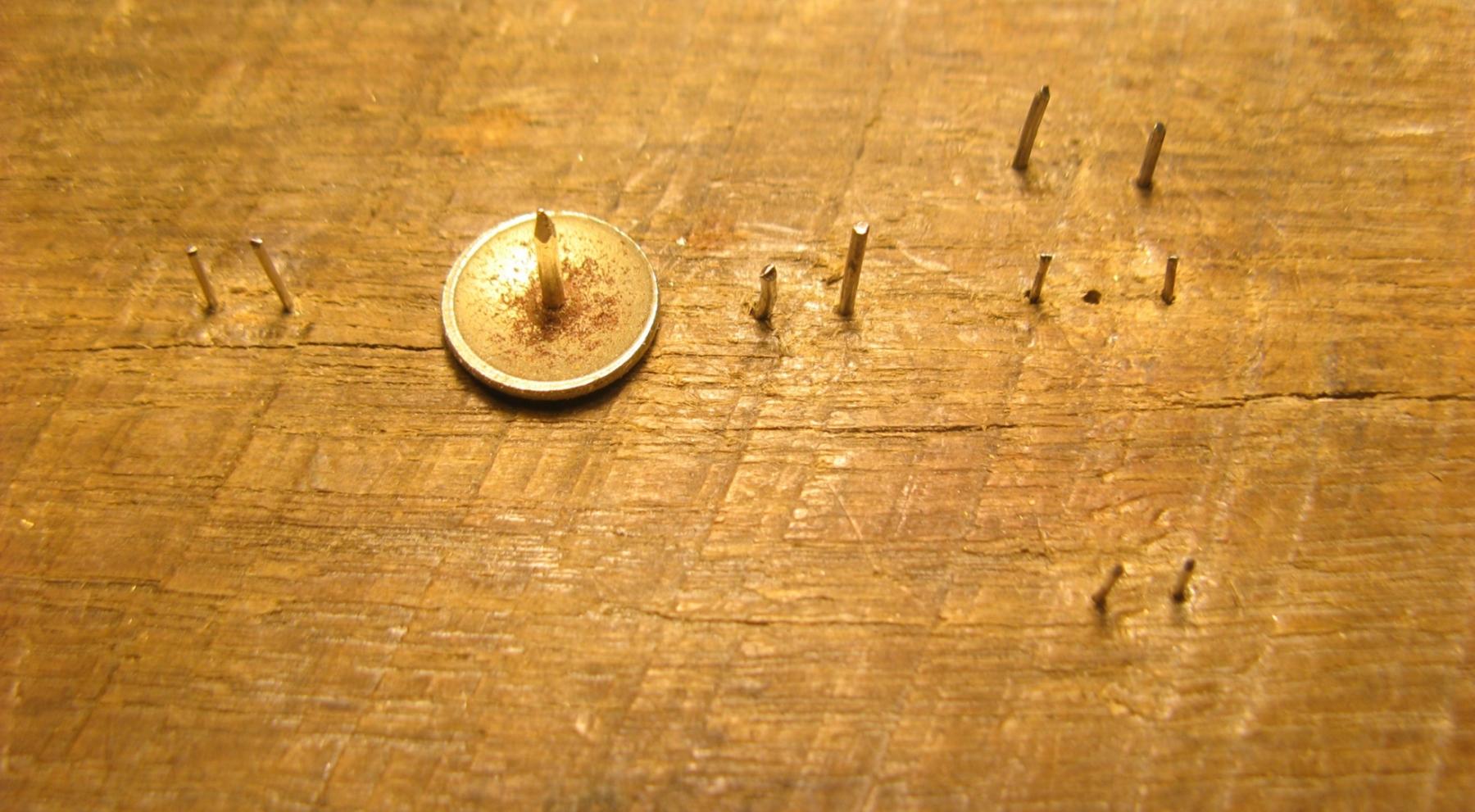
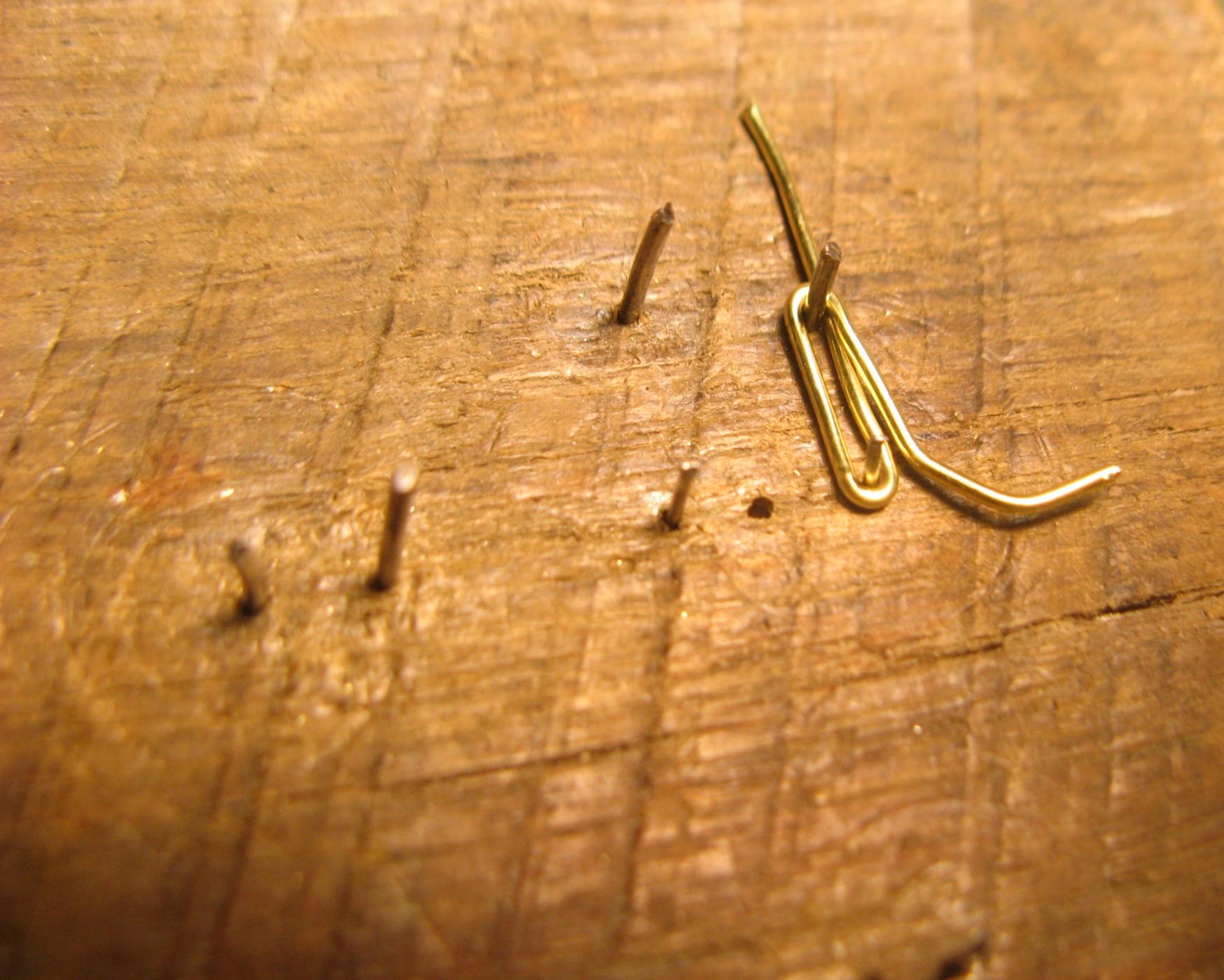
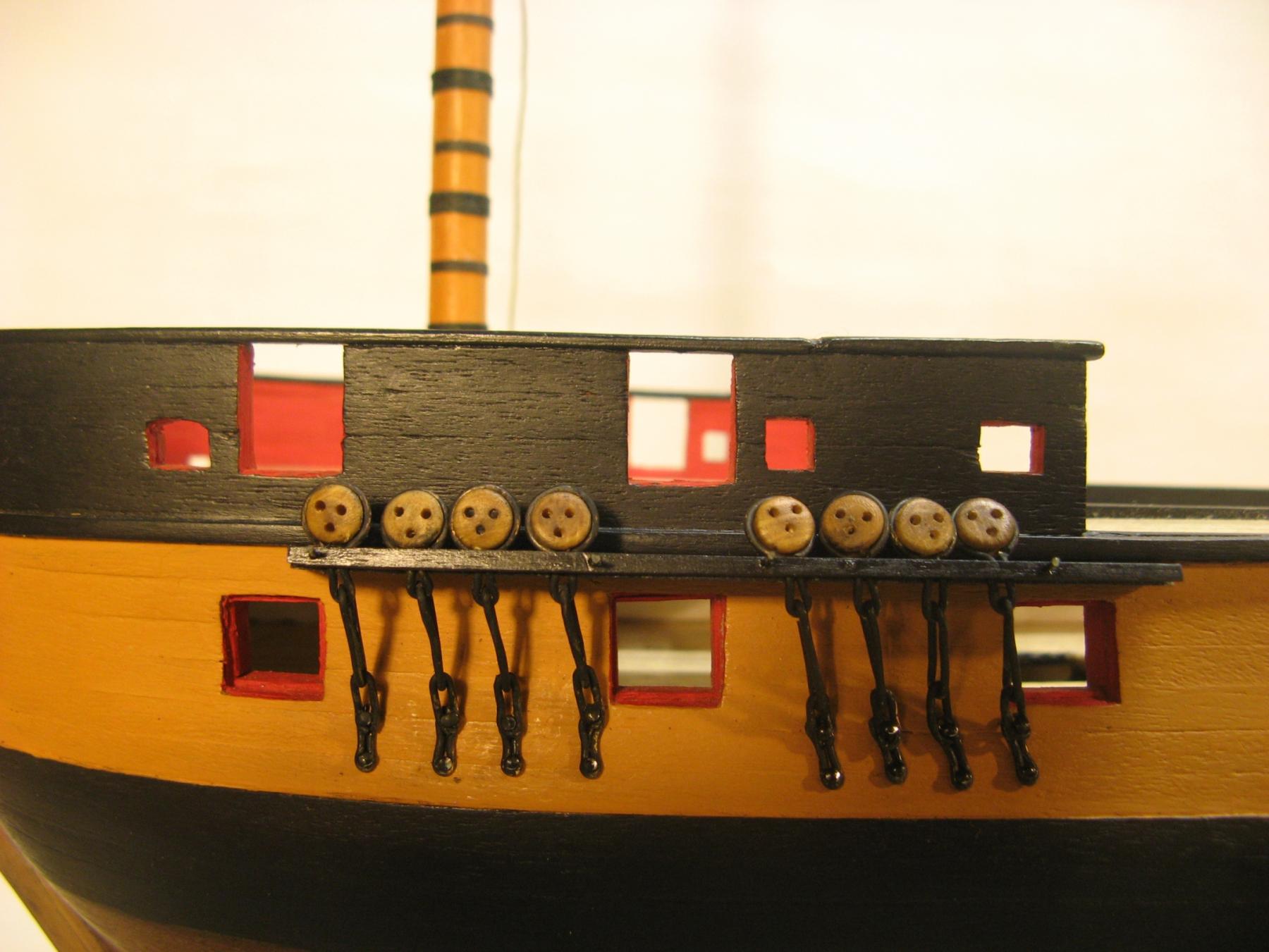
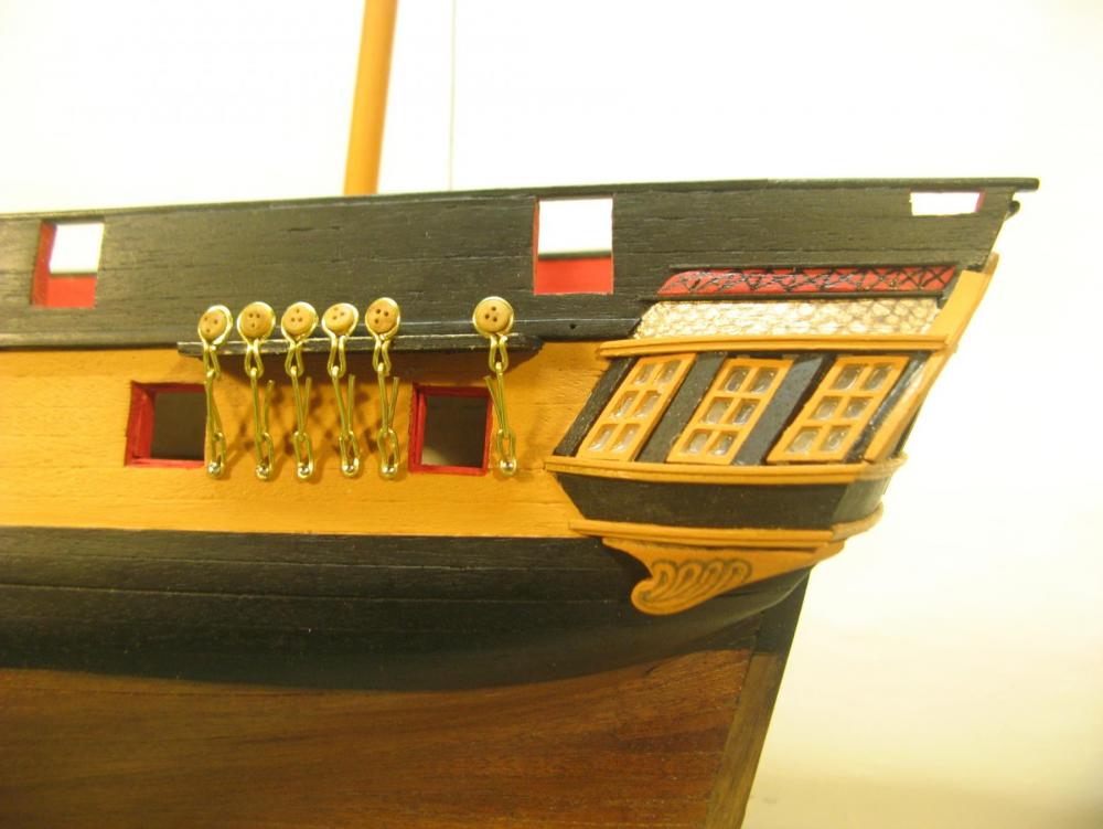
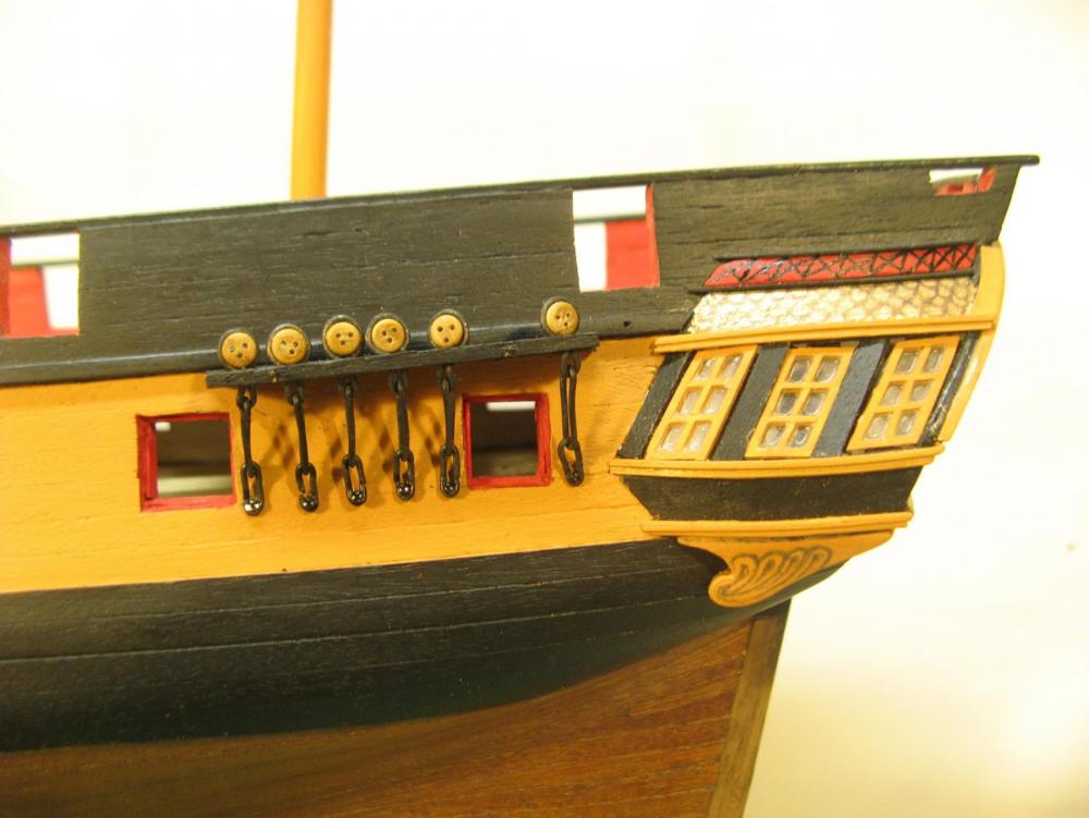
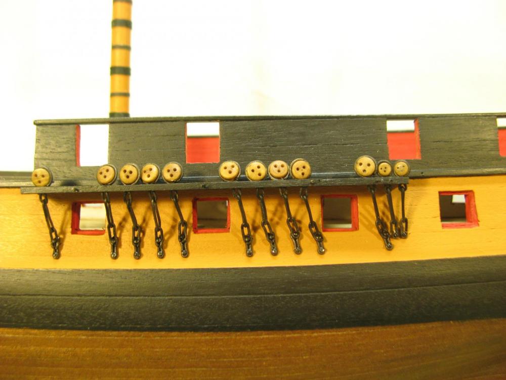
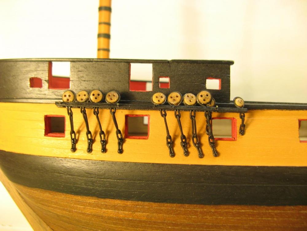
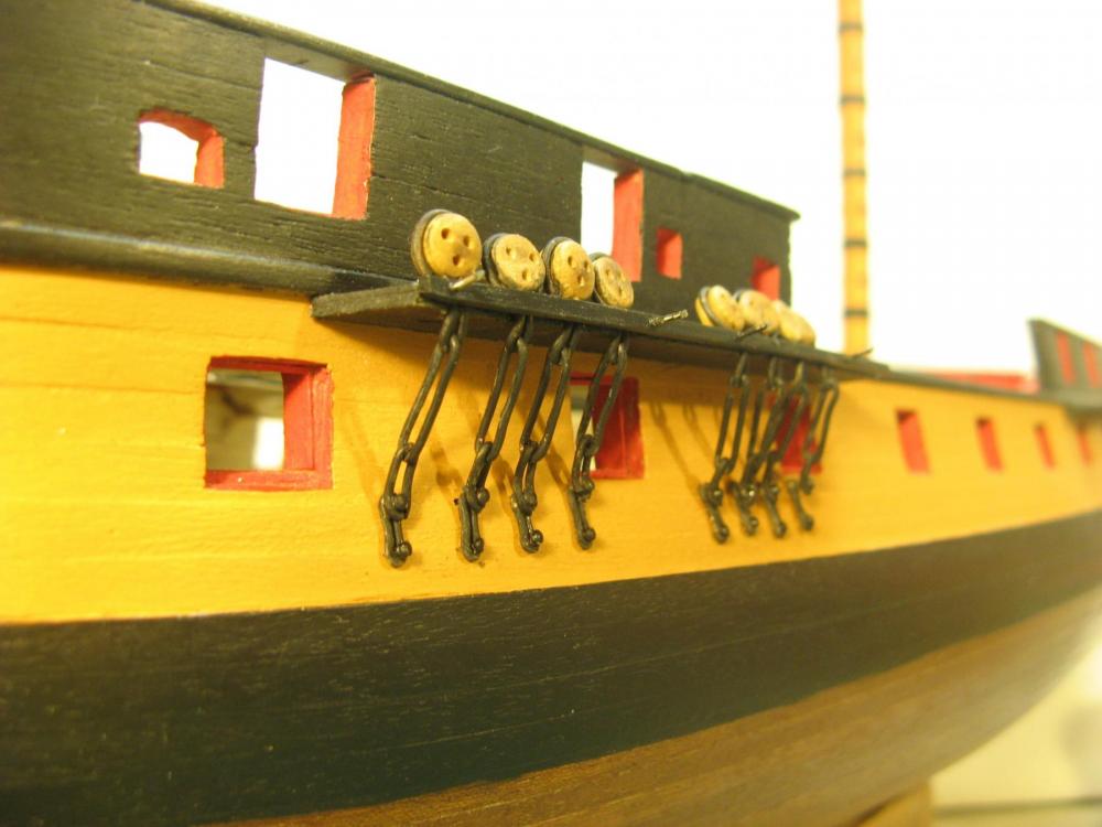
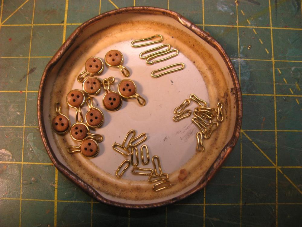
The port side chains are complete apart from a bit of final aligning and touching up. I use a jig of sorts, a block of hardwood with lots of wires of 2 sizes at different spaces for the various chain parts and positions. The 2 sizes are for the the fixings to the hull which are 0.6mm sewing pins and 0.8mm which is the thickness of the brass wire for where the links connect to each other. The large rod is for the dead eye rings to shape the bottom connections of the dead eyes. Fortunately the brass wire that I found is fairly stiff so it holds a shape pretty well and I will not be soldering the joints. Once the chains have been finally adjusted I will CA the dead eye bottoms at the channels so that load from the shrouds and back stays is not transferred into the chains themselves. I think the starboard side will be neater than the port side and by the time I have finished I will probably be pretty good at making up chains. Of course all will be forgotten when the time comes to make them up for the next build. I have found this to be a fairly painful process. This much handling of small fine pieces of wire punctures the finger tips quite frequently and I'm getting quite a layer of scar tissue. I cut the shaped chain sections with side cutters then grind the ends flush with a disc on my Dremel. I have brushed the edge of the disc a couple of times with a finger. This smarts too! Heart and soul into a model obviously isn't enough, some blood also helps. Cheers, David.

-
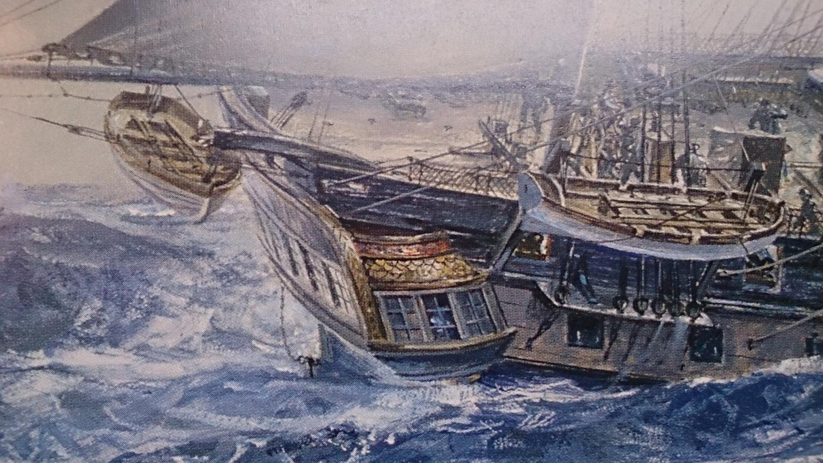
The credits are rolling, I have just finished watching Master and Commander for the third time but after many years. A wonderful experience, it brings the Surprise to life once again. The joy of Aubrey and Maturin continues. I have just finished reading the Thirteen Gun Salute for the scond time and am thoroughly enjoying the entire book series again. Gleaning details of the Surprise from the books is an added bonus.
-
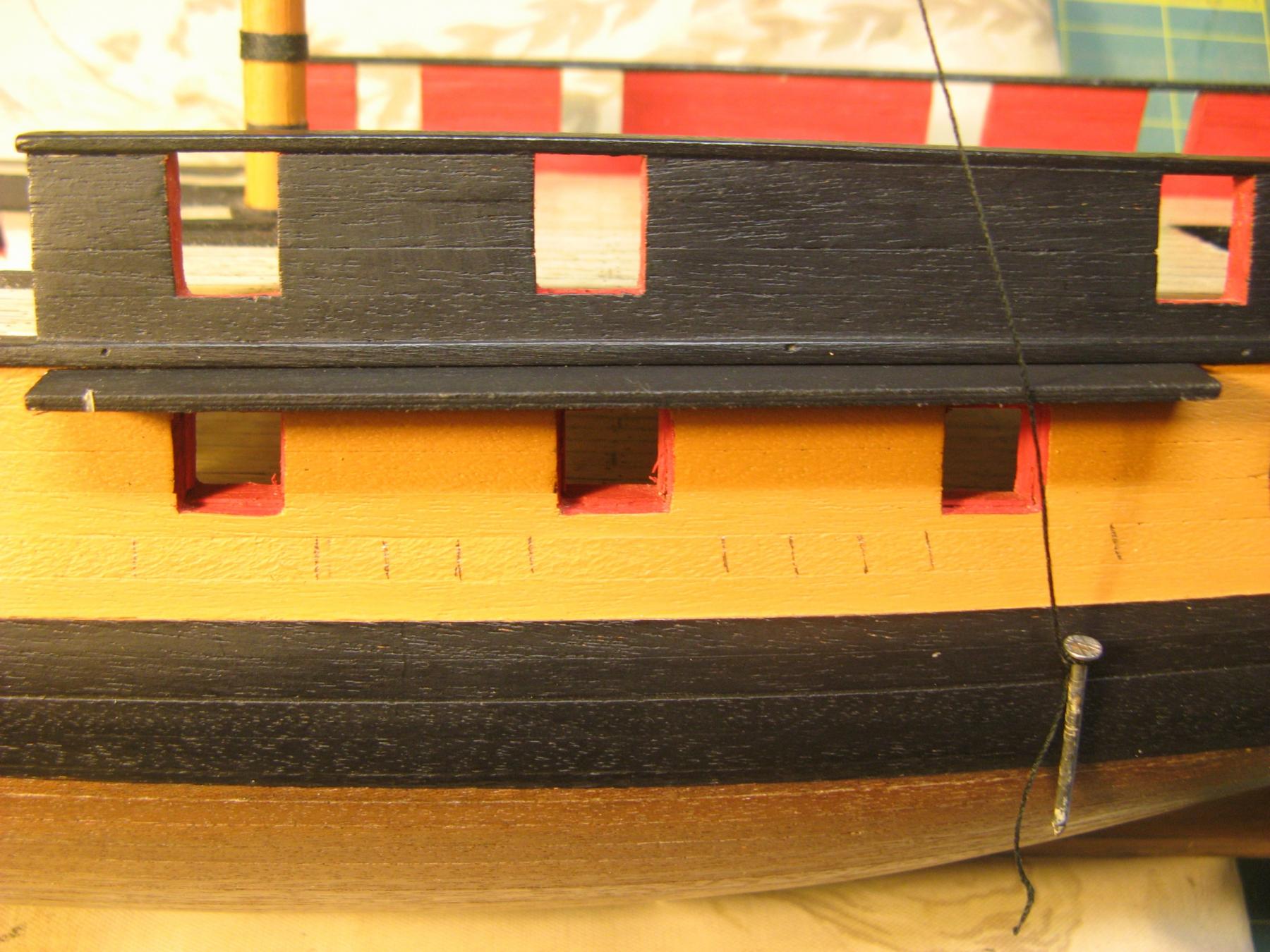
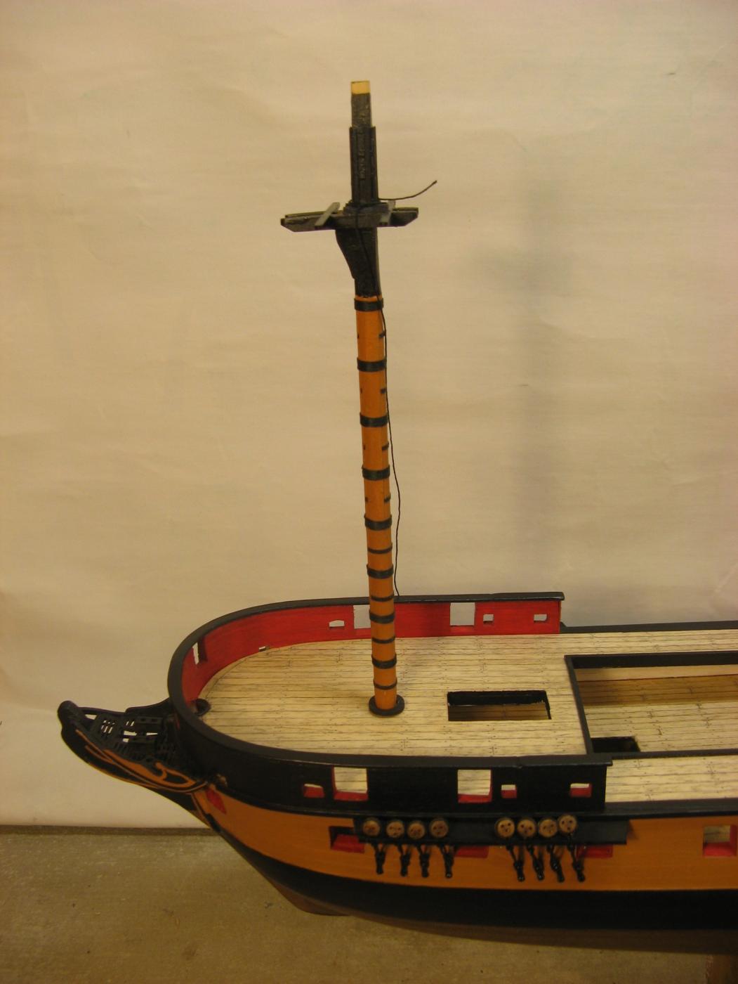
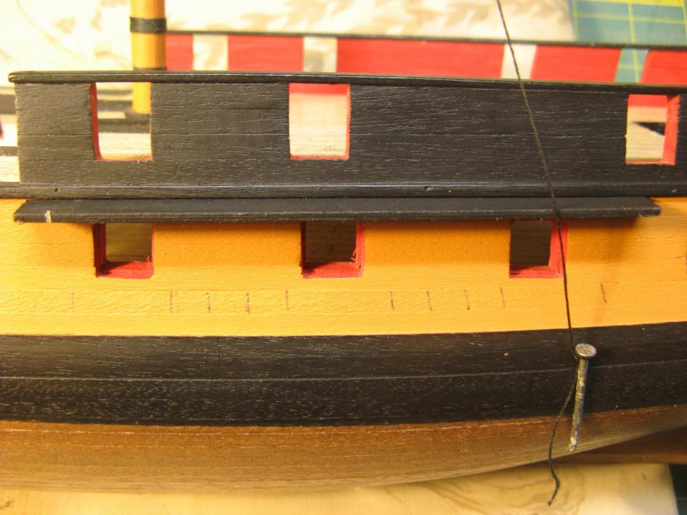
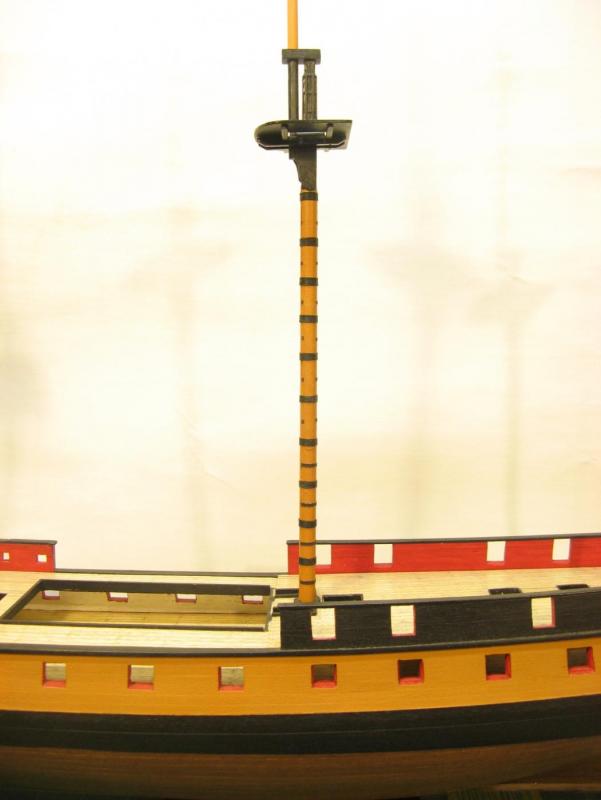
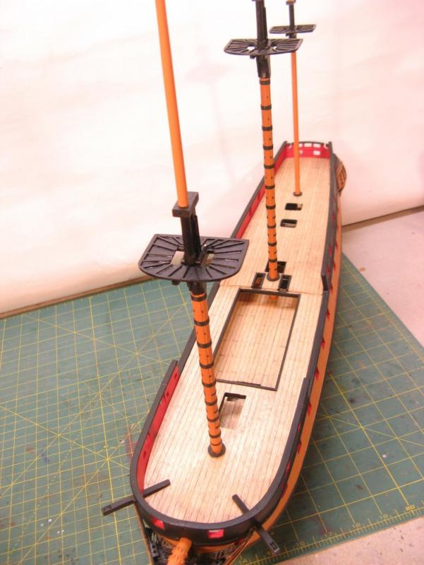
Chains. Having the lower mast sections now makes it possible to plot the angles of the shrouds and chains. Port side fore mast chains installed. The port side main mast chain angles have been marked out with a weighted string from the main top. The chains are made from 0.8mm brass wire which I finally found at a haberdashers. The brass is chemically blacked then touched up with matt black paint. To maintain a horizontal line for the bottom of the chains one of the lengths needs to vary in length as the changing angle progressively increases the overall length towards the stern. I have decided to make the longest link vary so I have only pre-made those at the bow end as they are pretty much the same length and those further aft will be made up to individual lengths.


-
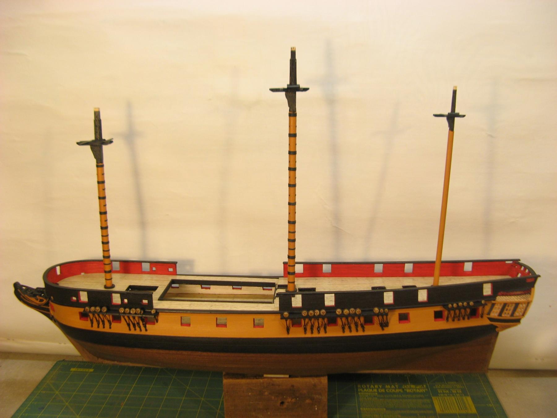
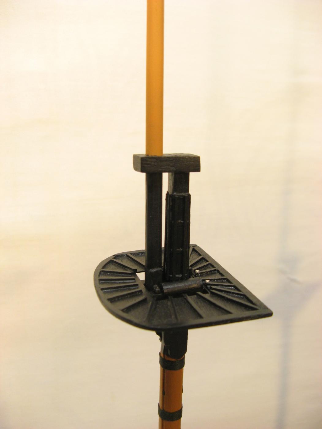
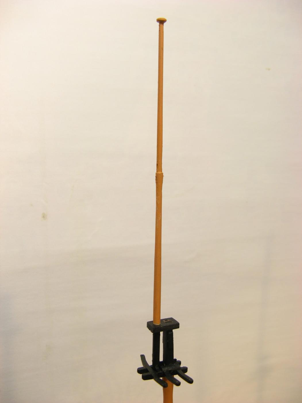
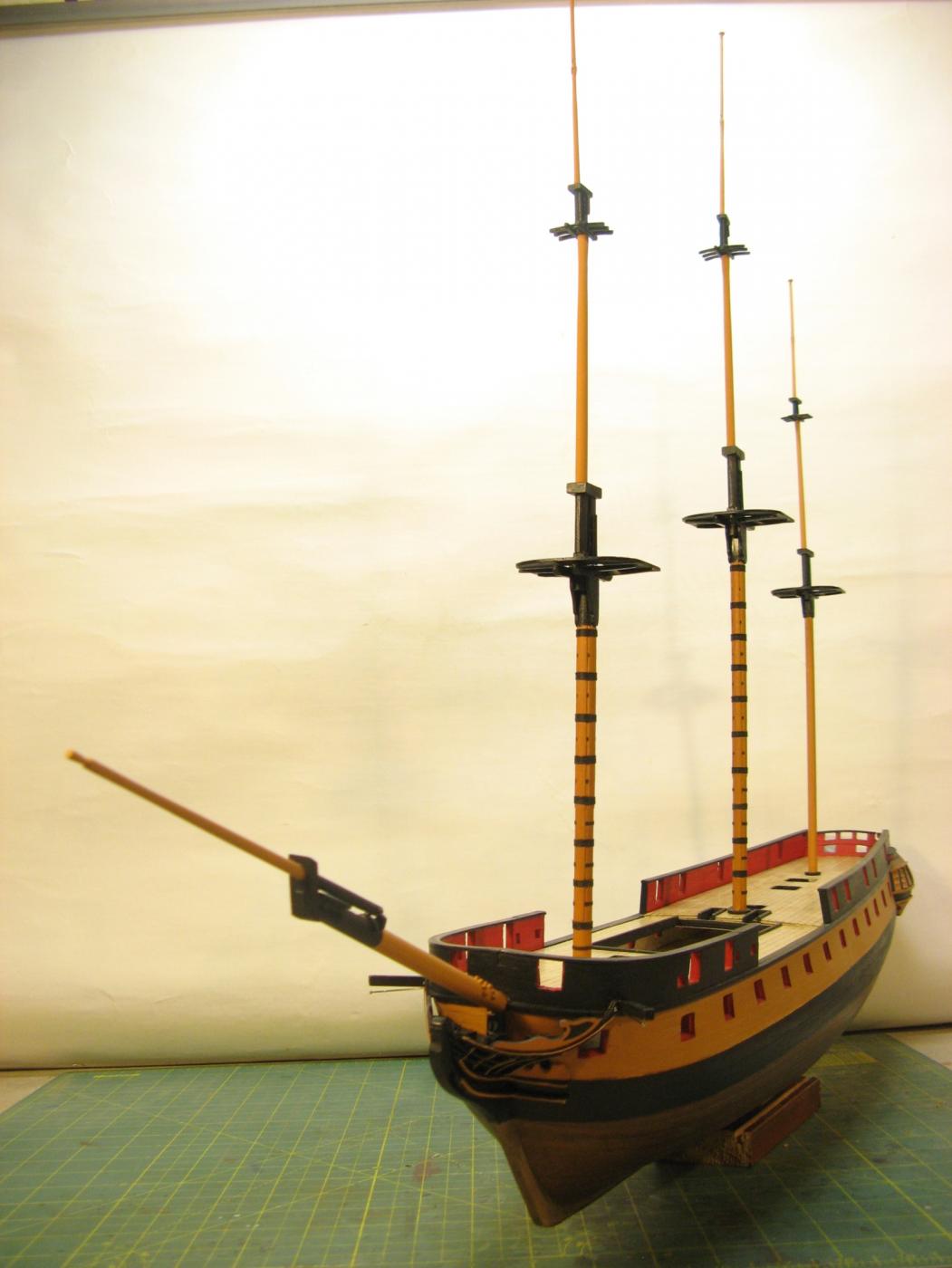
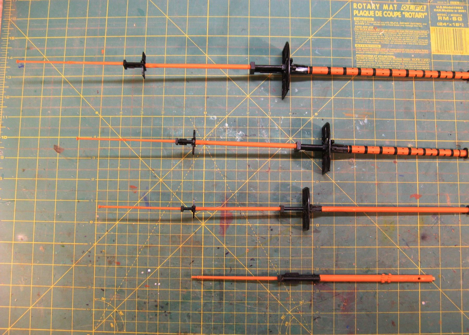
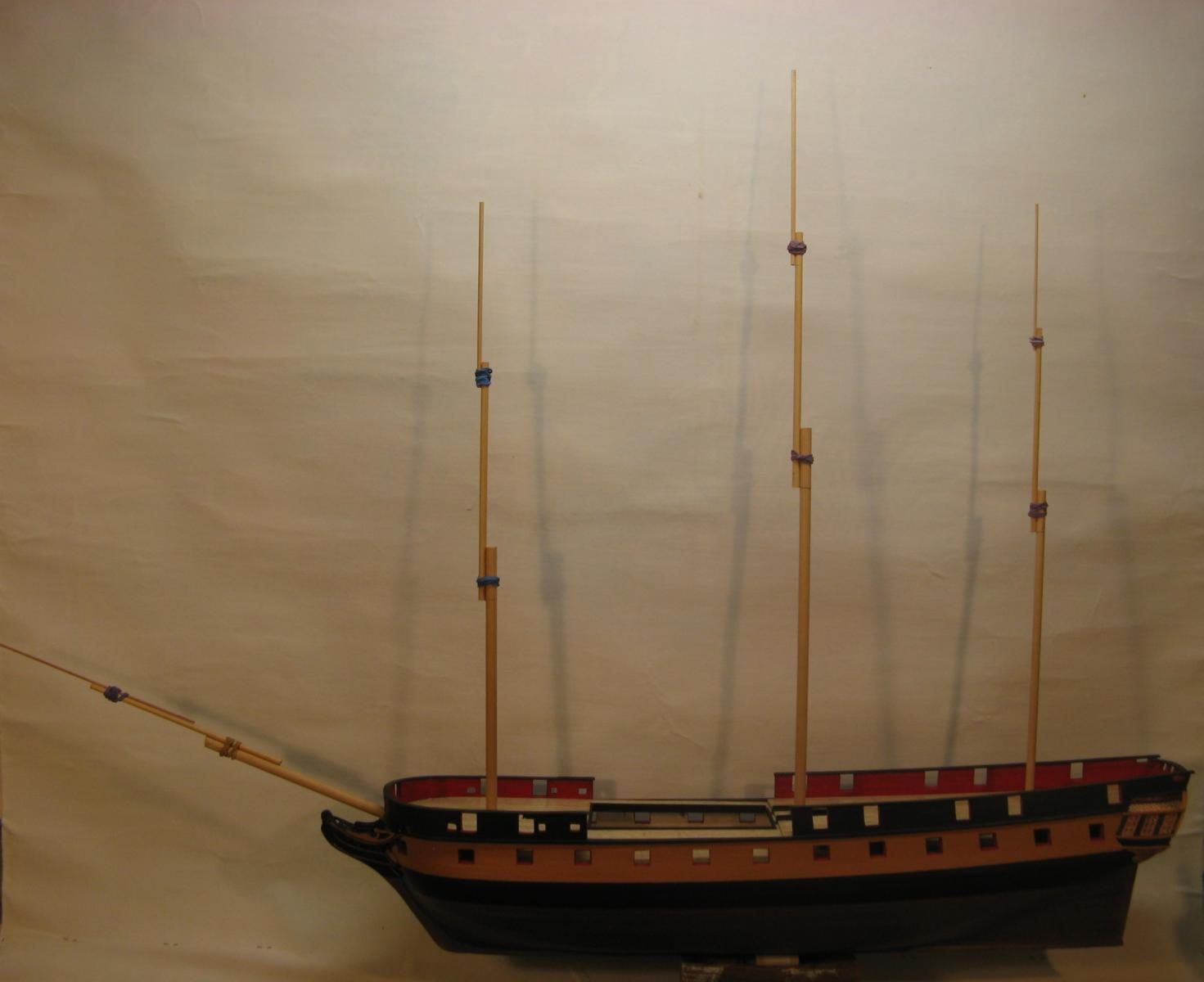
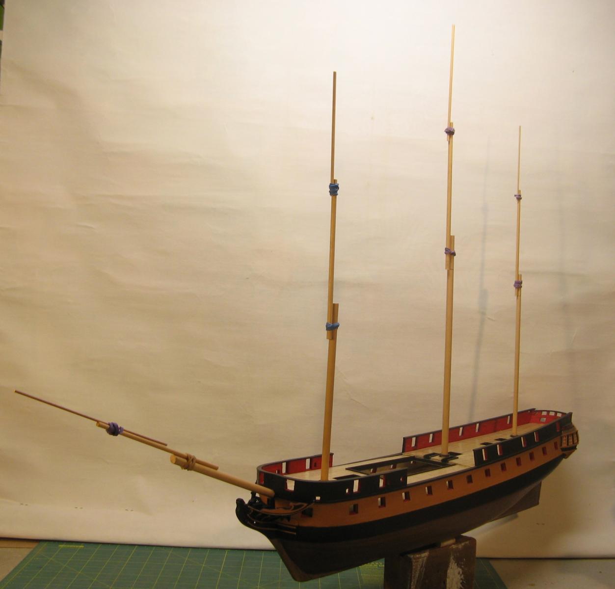
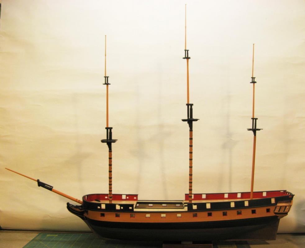
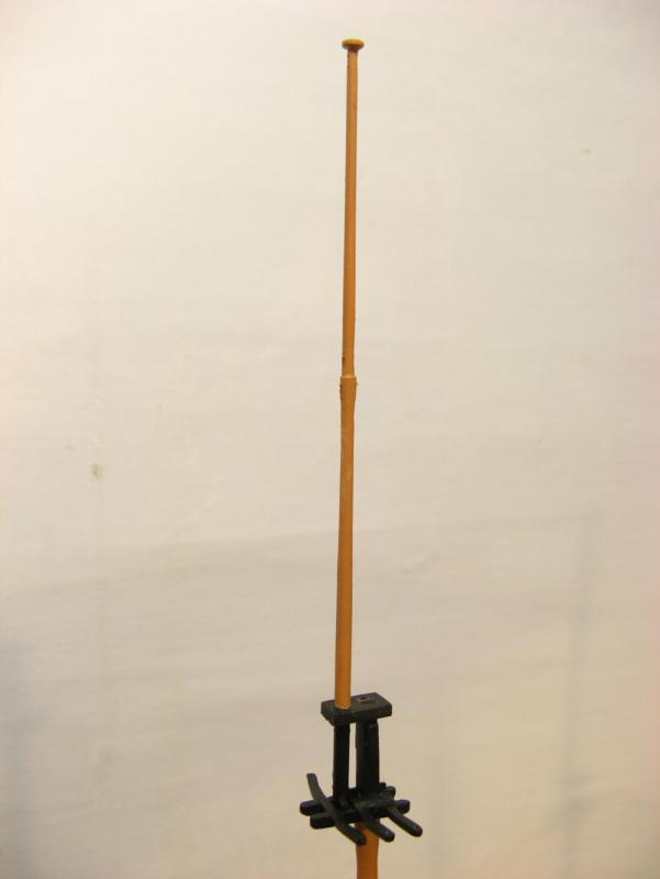
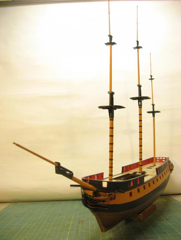
Mast progress. I had planned to make up only the lowest sections of the masts so I could set up the positions of the main shrouds for the channels and chains, the next step in the hull construction. But I got a bit enthused with mast construction so I made up the lot including tops and trestle and cross trees. All the sections are still dry loose fit so the alignment and rake is not fixed. Now I can get onto the channels. Cheers.


- 256 replies
-
- 12
-

-
Not so silly, but the quarterdeck and forecastle are removable to be permanently fixed in place further down the track. Cheers.
-
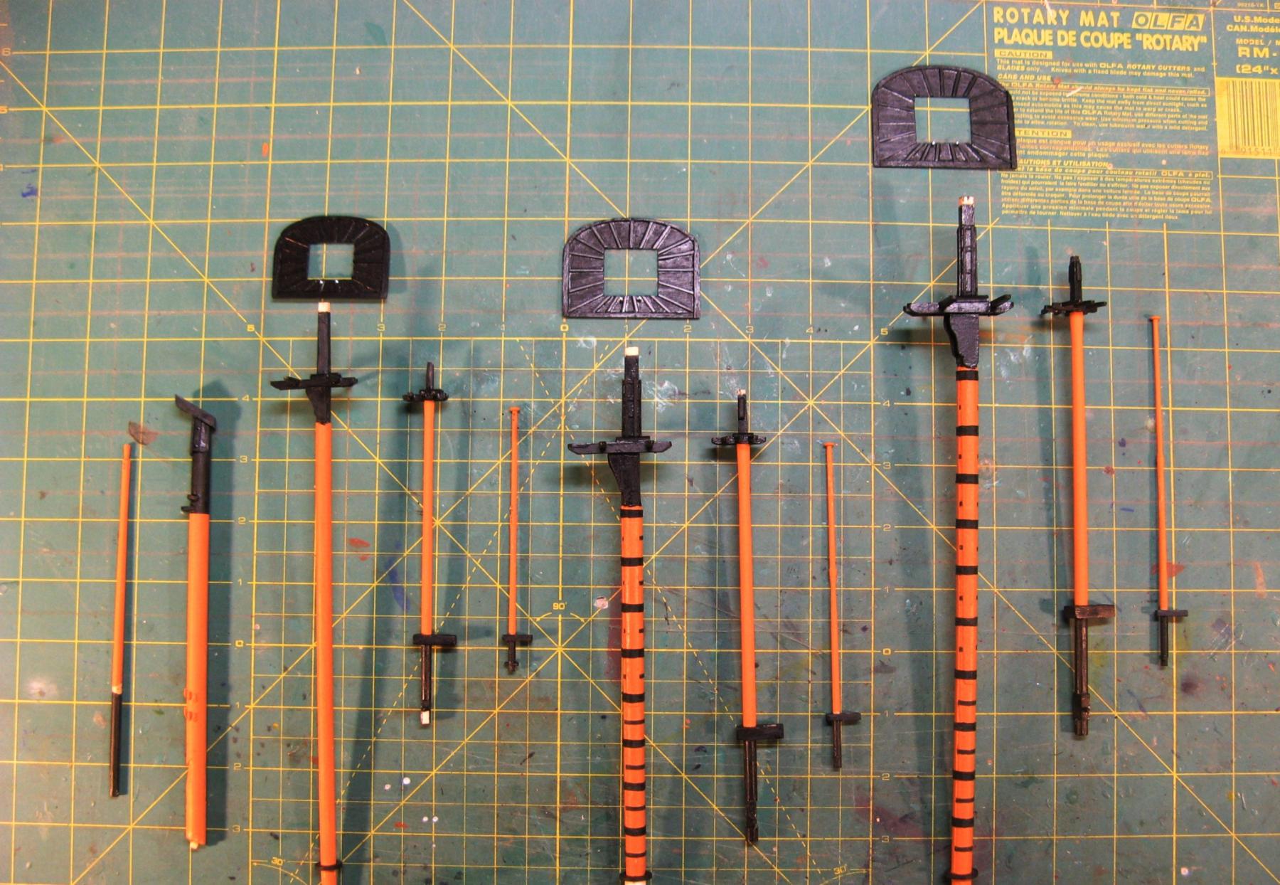
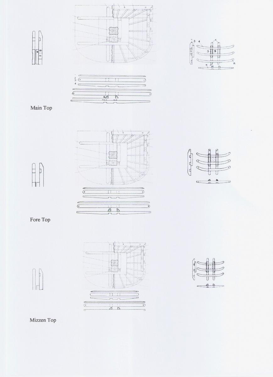
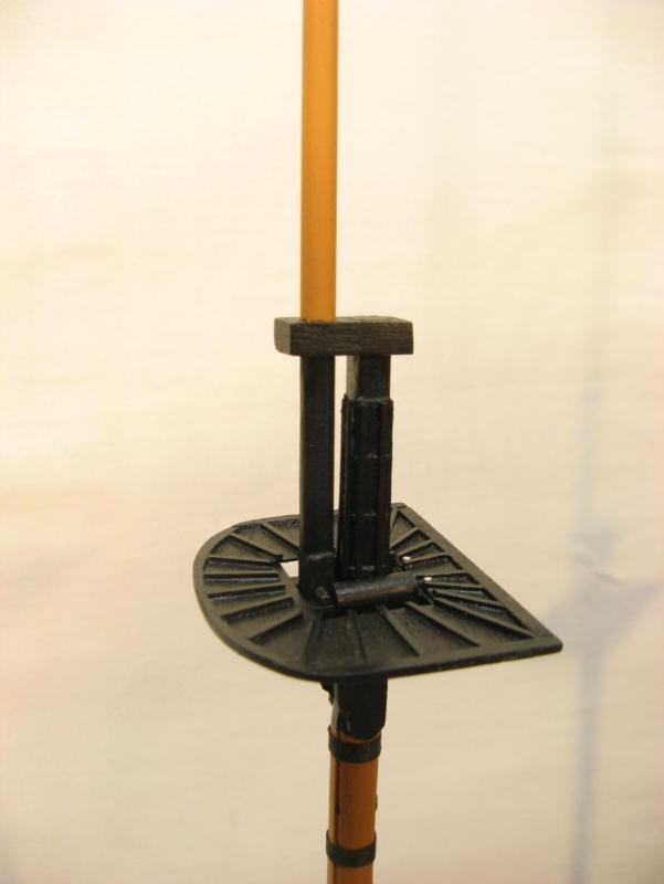
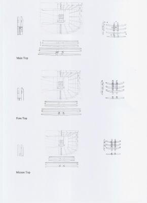
Tops and trestle/cross trees. A disadvantage of the scratch build path is the lack of detail drawings giving precise dimensions for items such as these. Some serious searching was required to find out just what size they should be. My initial attempt using various sketches, diagrams and descriptions, particularly a side view of the tops in Lennarth Pettersen's book, ended up with a main top which just looked too big when made up. Back to the search. "The Ship Model Builder's Assistant" by Charles G Davis has some very helpful schedules which define the sizes of tops and trestle/cross trees, along with all sorts of other parts, based on the length of a ship and the heights of the mast sections. Using this I have resized these parts and they now look more in scale. I copied the drawings for the tops from a pdf version of "Anatomy of the Ship, HMS Diana" pasted them into a word document then changed the sizes until correct, well, as close to correct as I can get. I only had a layout for the main top and I think this will also be OK for the foretop as they are pretty similar in size, I will simplify the framing for the mizzen top as it is quite a bit smaller. Cheers, David.
-
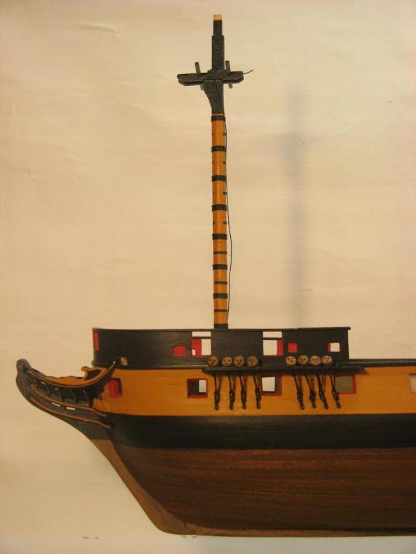
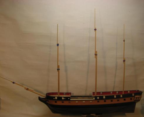
I have spent much time searching through my well thumbed Lavery & Hunt and know the sketch you refer to. To a large extent this sketch helped to define the mast heights and the overlaps at the tops. The final heights were an average of 2 or 3 different pics but that sketch finally defined the overall mast heights, mizzen slightly shorter than the foremast with the 36 gun lower section of the main mast together with the standard 28 gun frigate main topmast and main topgallant mast giving the distinctive triangular profile. Cheers, David.
-
Time for something a bit different. The next hull detail that I will build is the channels with chains and deadeyes. To get the correct layout the exact angle of the shrouds running down from the tops is needed and the best way to do this is to build at least the lower sections of the masts. I have decided to work to the fictional Aubrey layout with the standard main mast replaced with a 36 gun frigate item. Fortunately the Lavery & Hunt drawings include this layout so all that was required was some careful upscaling. This layout also includes a taller mizzen mast so this will also be included. To see what the overall mast layout looks like I have made up all the sections and rough joined them. Cheers, David.

-
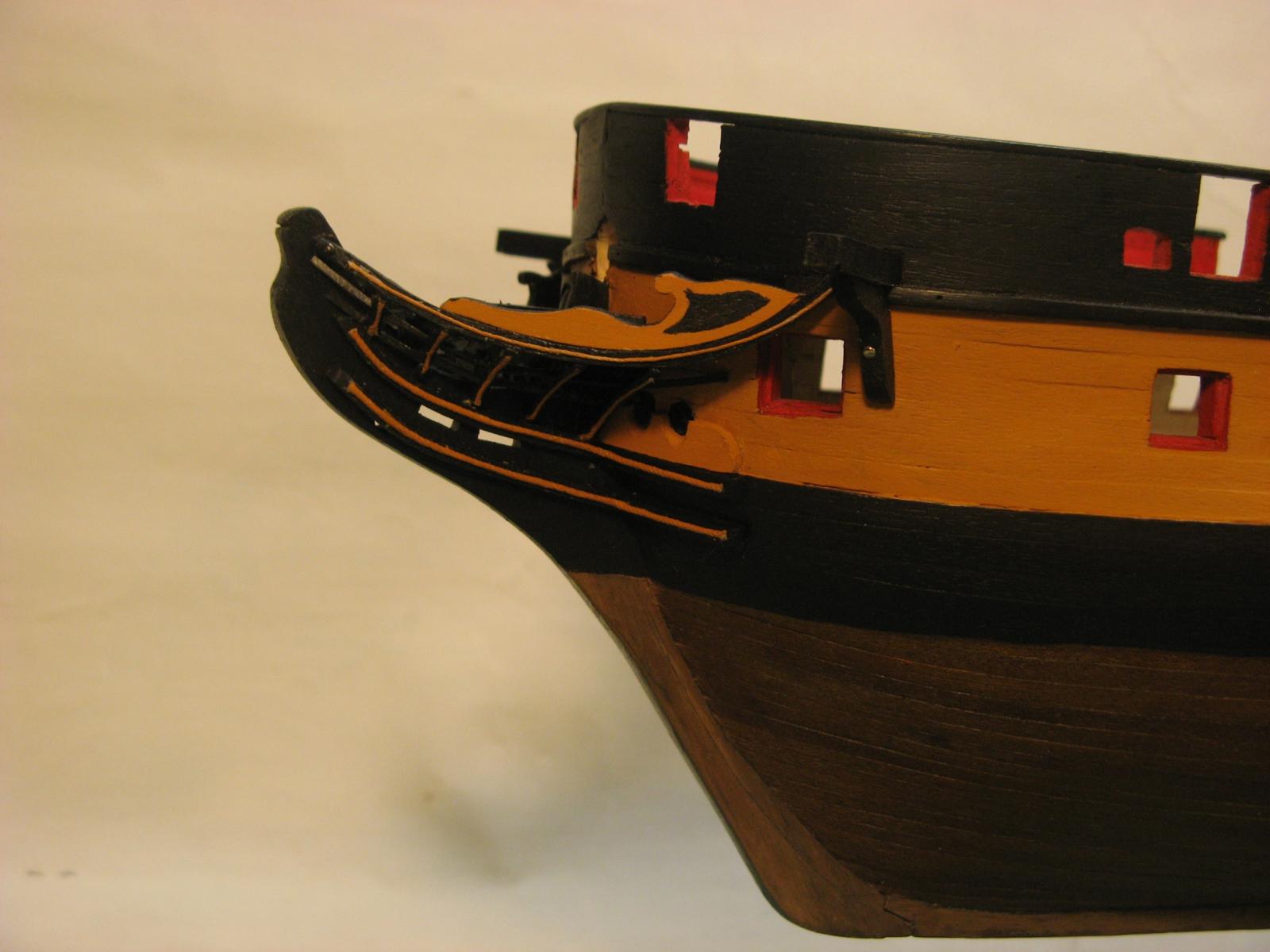
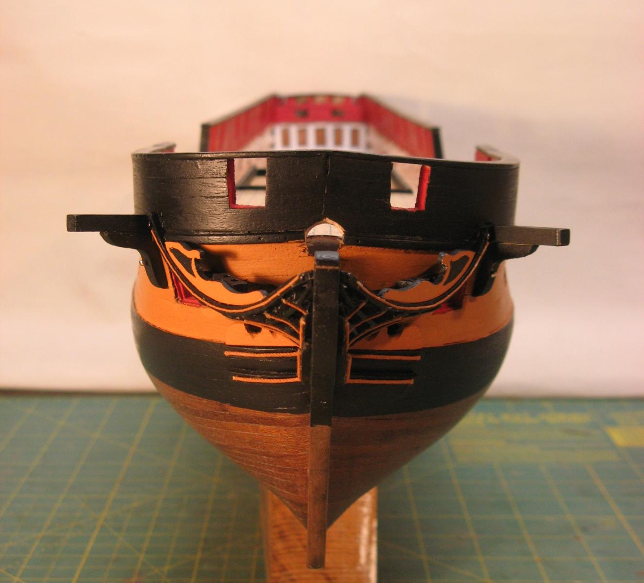
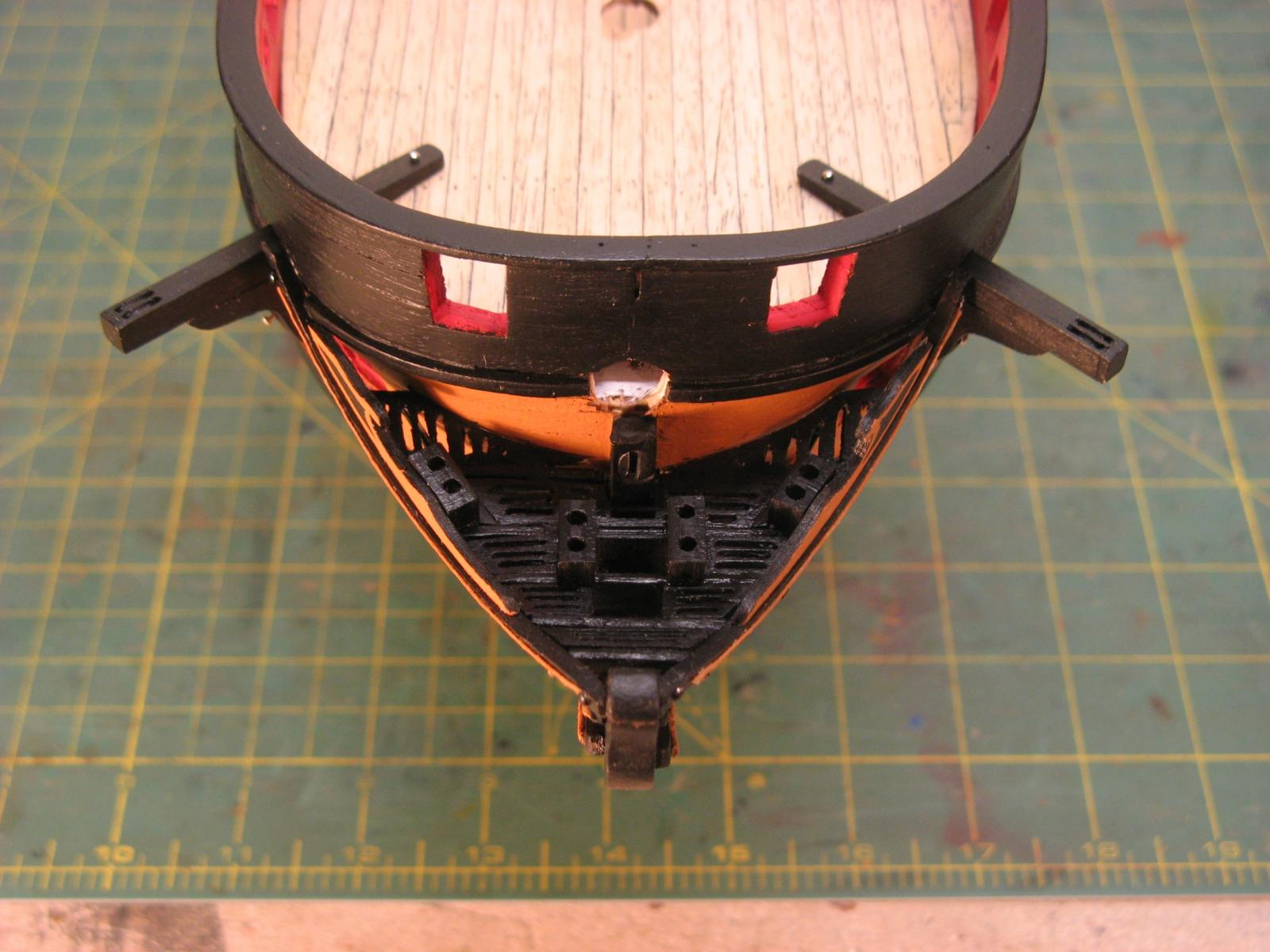
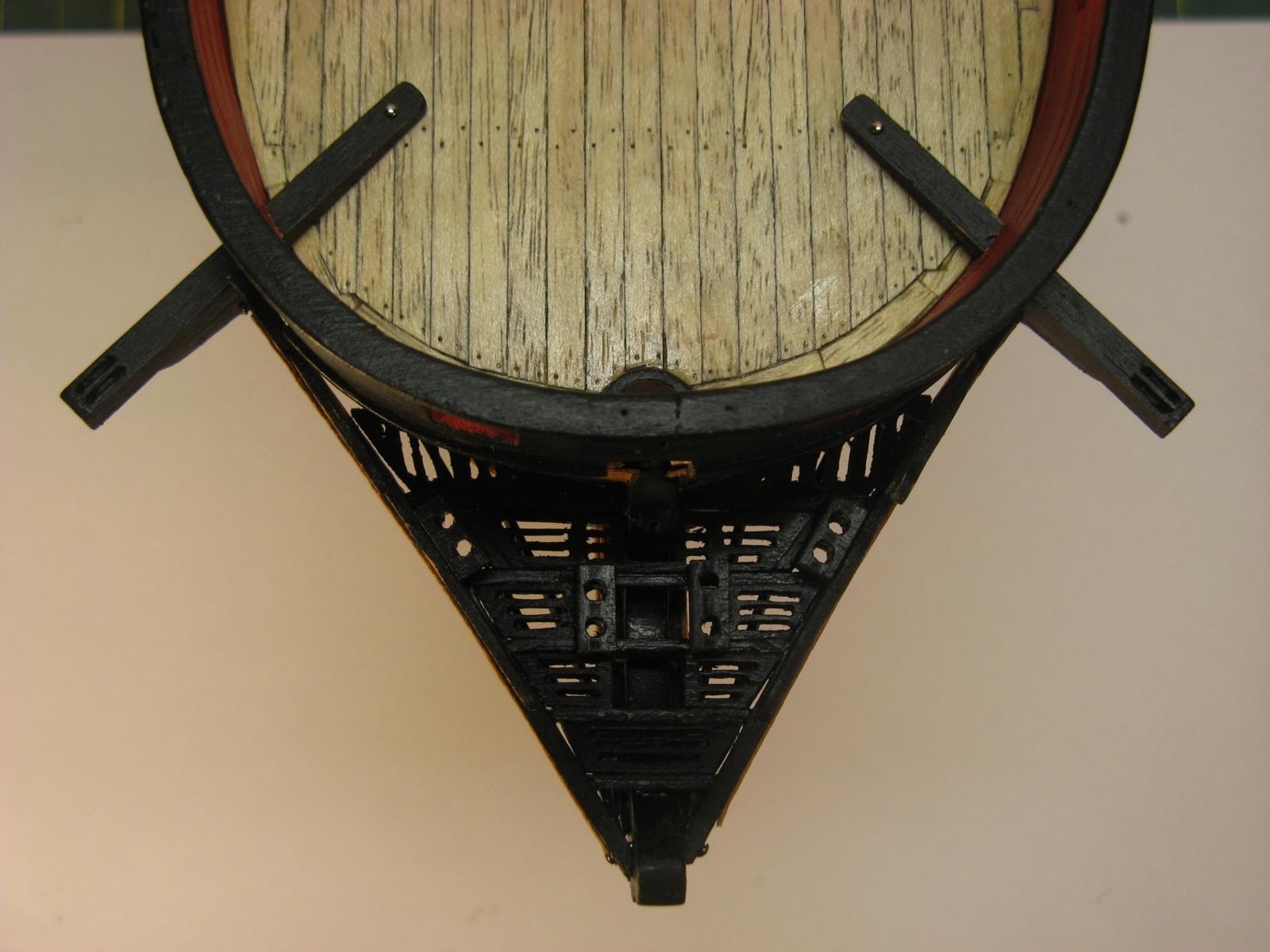
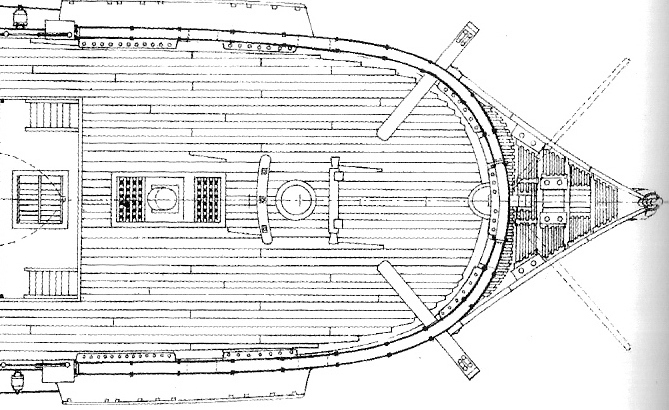
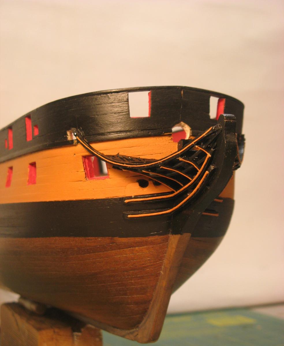
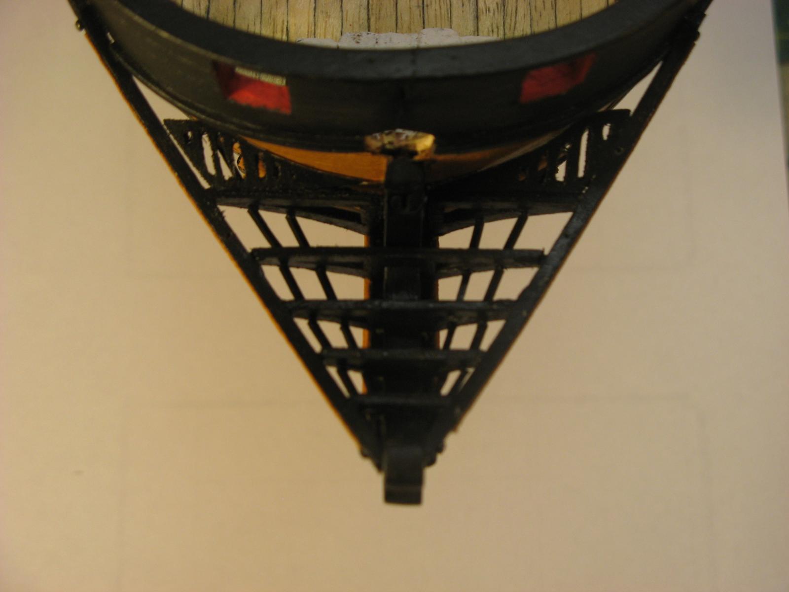
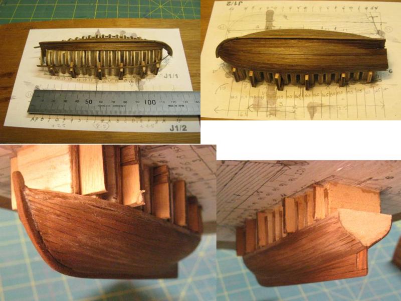
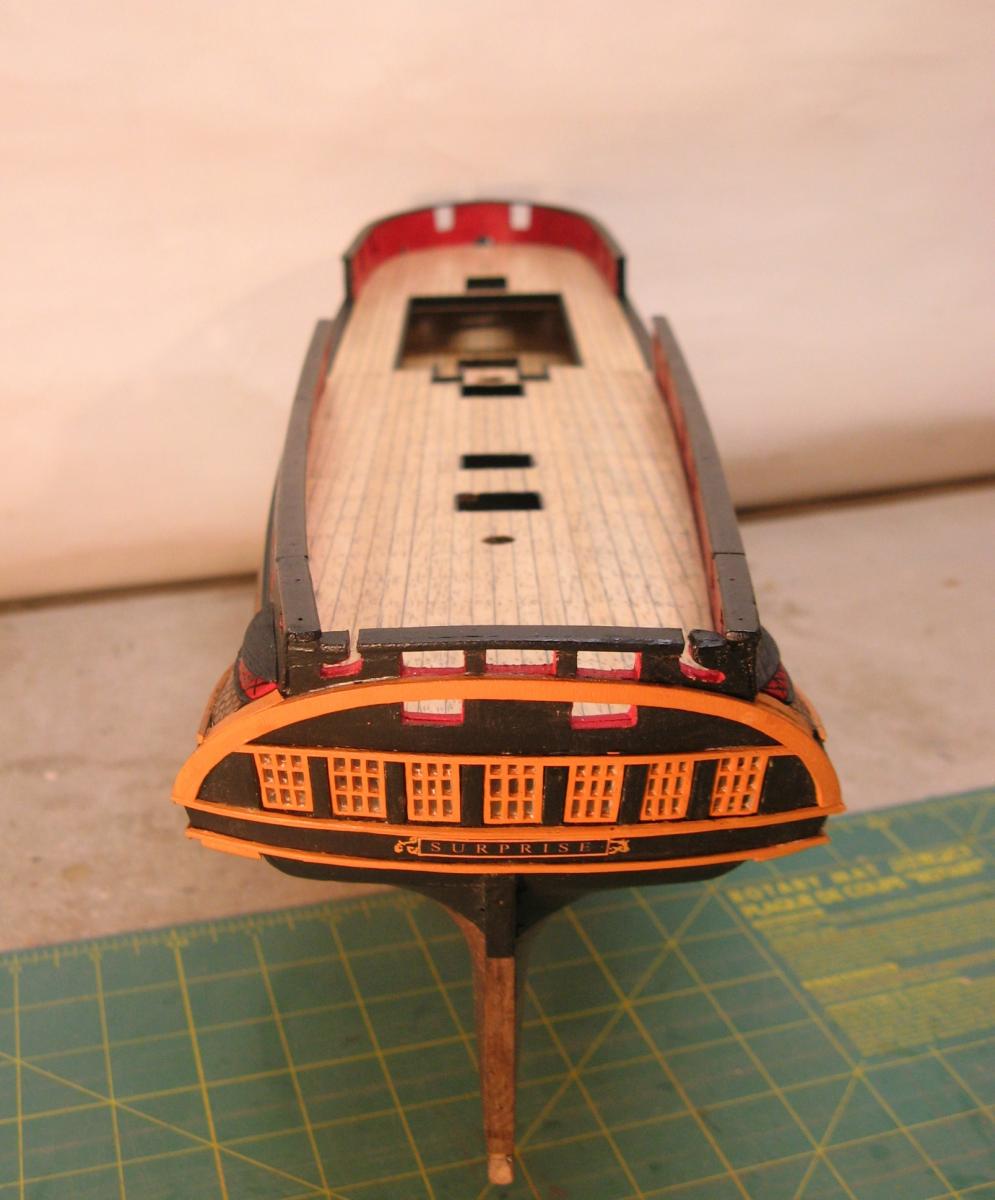
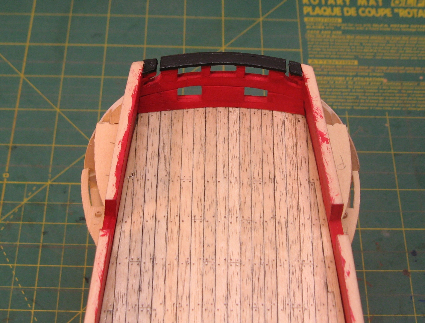
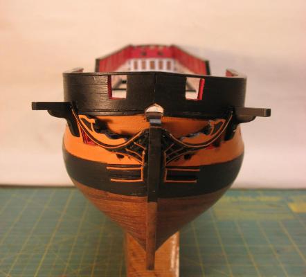
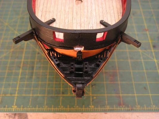
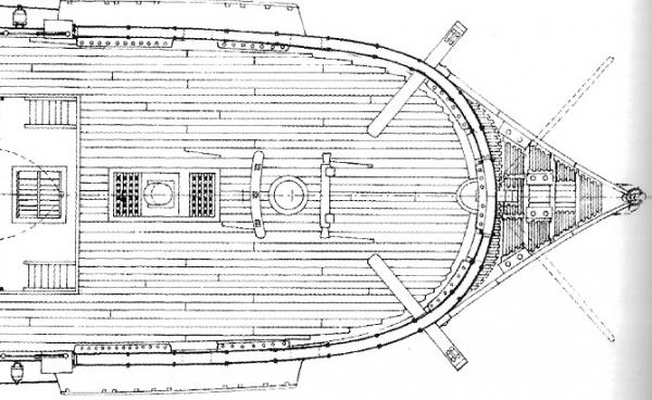
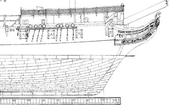
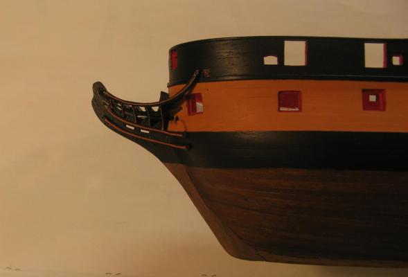
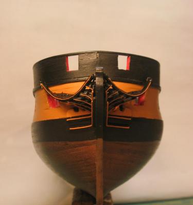
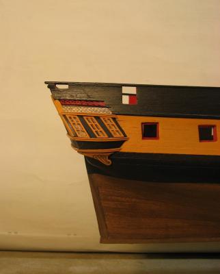
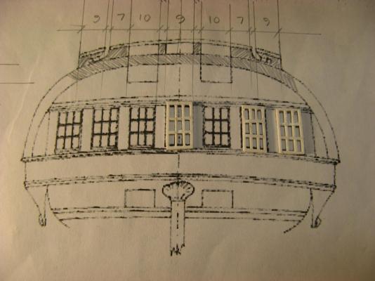
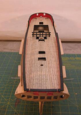
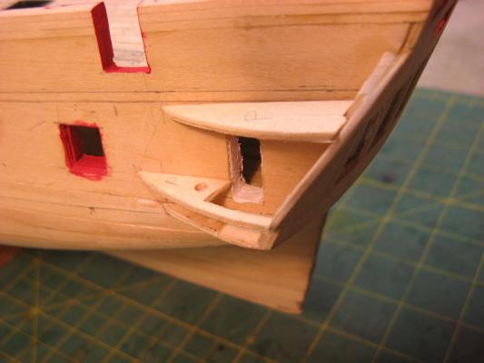
Some more bow details. The false rails, catheads, cathead supporters, ledges (gratings) and seats of ease have been added. The catheads and supports are dry fixed and the temporary pin fixings are because the forecastle deck needs to be removable for some time yet. Always an interesting subject, I find the number of seats of ease intriguing. The L & H/ Admiralty plans for Surprise clearly show 8 individual, 4 pairs of 2. This is what I have built. As I have not been able to find information of the same standard as the Anatomy of the Ship series for Surprise I have been using the AoTS book on HMS Diana as a reference for some of the details that are not clearly defined in the L & H Surprise book. One of the big variations is the number of seats of ease. The AoTS for Diana clearly shows a total of 2. Compare this with the French built Surprise with 8! Why the huge difference? Perhaps it has something to do with diet. Possibly French cuisine of the late 17th, early 18th centuries was much more sophisticated than the English equivalent. Did this carry over to their warships? Did French sailors have a much greater need than their English counterparts? A friend that I discussed this with had a simple answer to at least halving the discrepancy, his suggestion was that the pairs at the head of Surprise didn't represent twice the number of facilities, half of them, in the European tradition, were bidets! Not sure about that. Any contributions to this discussion would be most welcome. Cheers, David. Lavery & Hudson head details


-
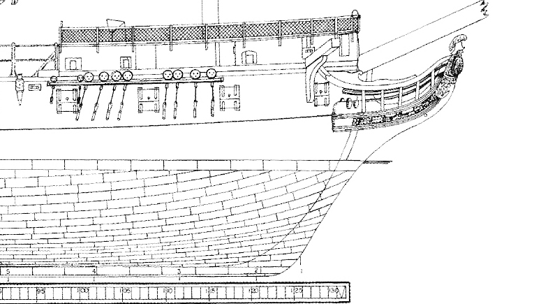
Progress on the bow details. Like many things there seem to be numerous alternatives as to how the head timbers, rails etc are configured. The most significant difference I found was which of these items was visually dominant. Some images I found had the rails outside the head timbers so the rails were continuous, others had the rails inside the line of the head timbers so these were continuous and some had both in the same plane so they formed a sort of 2 dimensional grid. The drawings in Lavery & Hudson seem to show the vertical head timbers as being more visible and continuous so I have gone for this arrangement. it would have been much easier to have the rails continuous on the outside of the timbers as fitting the short rail lengths between the timbers and keeping them aligned was a bit of a challenge. in reality I guess the rails would have been continuous and fitted through the timbers but I was not up to that. I found it interesting to find pics of models where the main rail had been fitted much lower obstructing the forward gun port. In fact some models had deleted this pair of ports completely. As it is I will have to be careful how I fit the port lids in the open position. The most obvious missing piece is Athena the figurehead. My fine carving skills are non existent and trying to craft this myself would involve a massive learning process. A tempting option could be to write a polite email to Mamoli who make a 1:75 Surprise kit and ask for their version to be sent. Although learning to carve could be quite interesting. I'm sure that Janos could give some pointers. Next are the gratings and seats of ease which sit above the head timbers. These have been made up and painted. L & H/Admiralty drawing


-
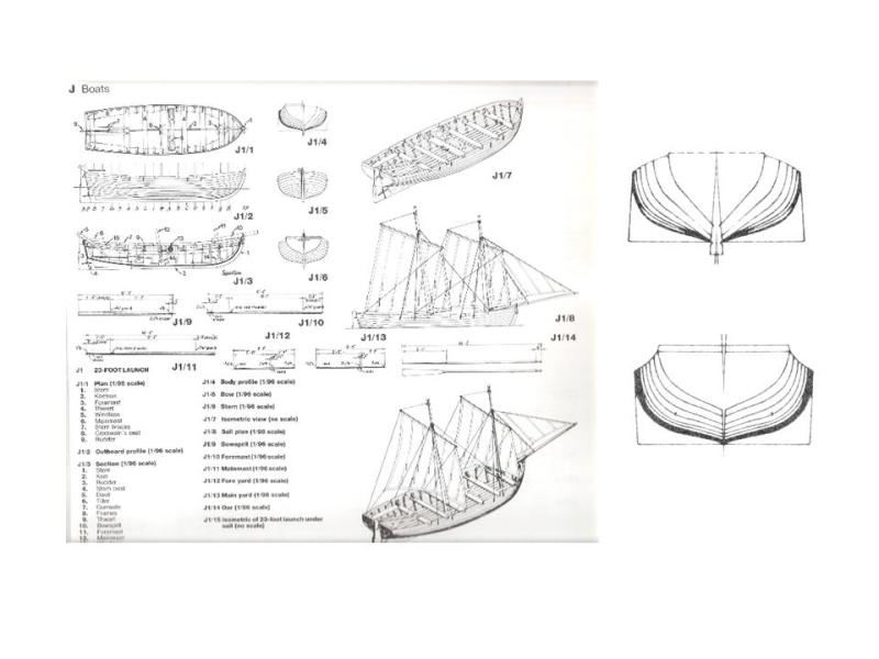
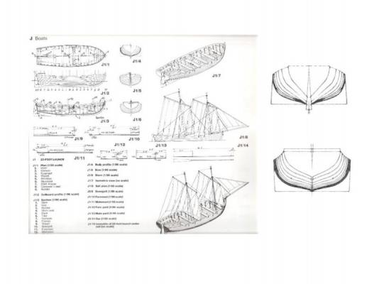
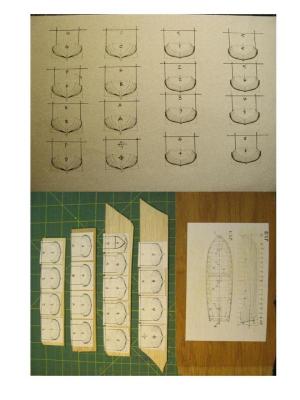
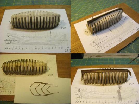
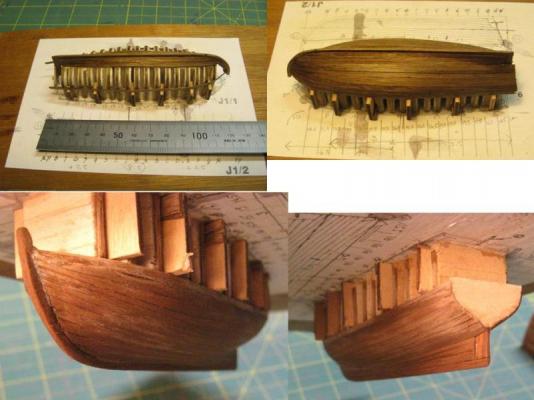
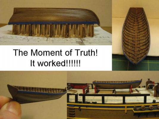
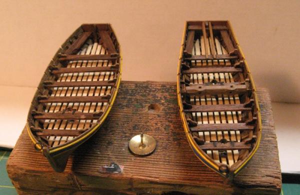
Hi All, Back from Christmas / new year holidays and time to get back into construction. Bow detailing and for a bit of a distraction I might start on the ship's boats. There are 4 main different types, the drawings in Lavery & Hunt (L & H) show construction of 5 different boats, launch, cutter, jolly boat, pinnace and skiff, I haven't seen any images with the small skiff shown, they might have been stored out of sight. In the "Mauritius Command" notes at the back of the book describe 5 ship's boats, 28' barge, 28' launch, 2 x 24' cutters and 18' jolly boat. Where the boats were stored is a bit of a mystery. Various L & H images show different things. The Hunt painting on p59 is a good view of the deck and shows 3 boats in the waist (2 stacked), one on stern davits and one on starboard davits. If another was on port davits it is hidden behind the mizzen sail and that would make 6! The L & H Admiralty plans clearly show 4 boats, launch centred on the waist beams, pinnace on starboard davits, cutter on port davits and jolly boat on stern davits. Another Hunt image (cover of "Wine Dark Sea") on L & H p53 shows 3 boats side by side over the waist. If there were 3 more on davits that would make 6 again. L & H image on p94 shows 5, port and starboard davits, 3 at the waist, 2 stacked. So it looks like I have a bit of freedom to position boats where I think they look best. I intend to make 5 as described in "Mauritius Command" and will locate 3 on the davits and 2 in the waist, stacked. This means that the waist won't be too cluttered and details on the main deck below will be able to be seen. I will use the same boat building method as i did for the Bounty boats, balsa blank with rib and plank construction. In answer to the question about stern decoration I used gold paint and a fine blade type drawing pen with paint for the detail. The original ship's boats pics were lost when MSW 1 vanished but here they are again: Cheers, David.
- 256 replies
-
- 14
-
-
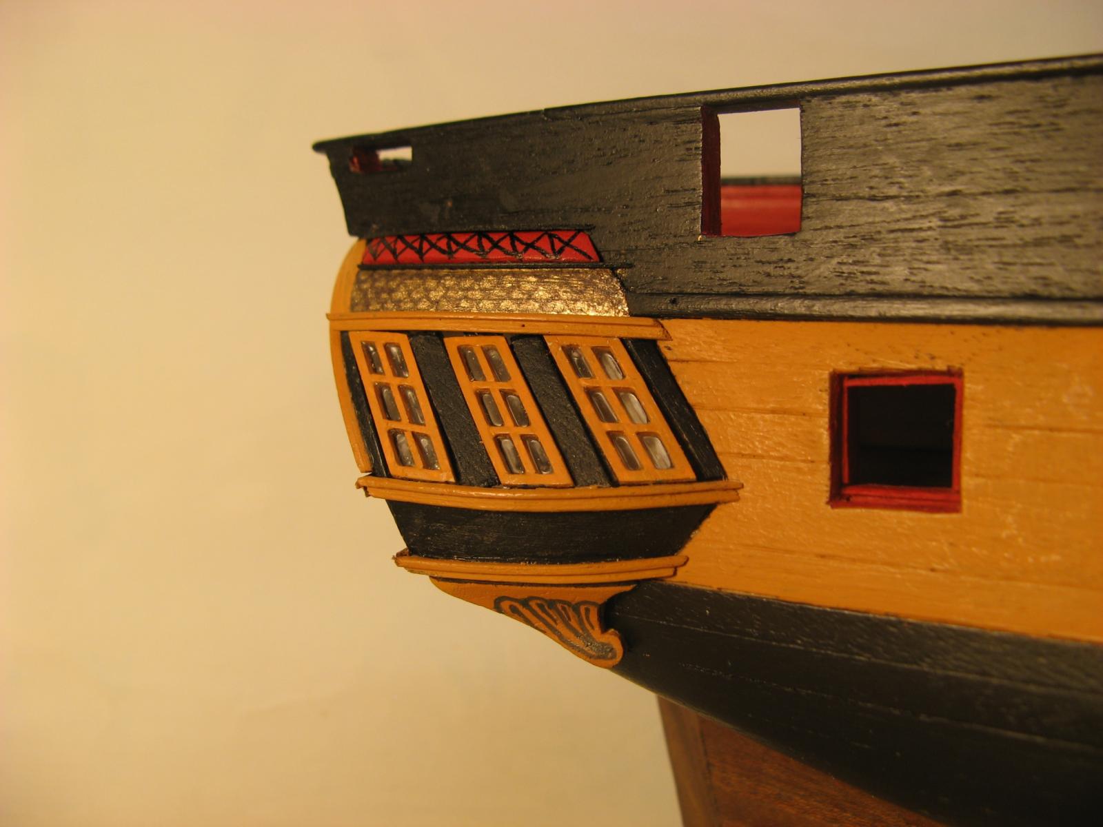
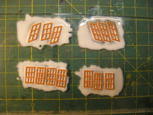
The PVA dries clear, what you can see on the close up is the white paint on the inside of the quarter gallery. Get up close and you can see through the windows.
-
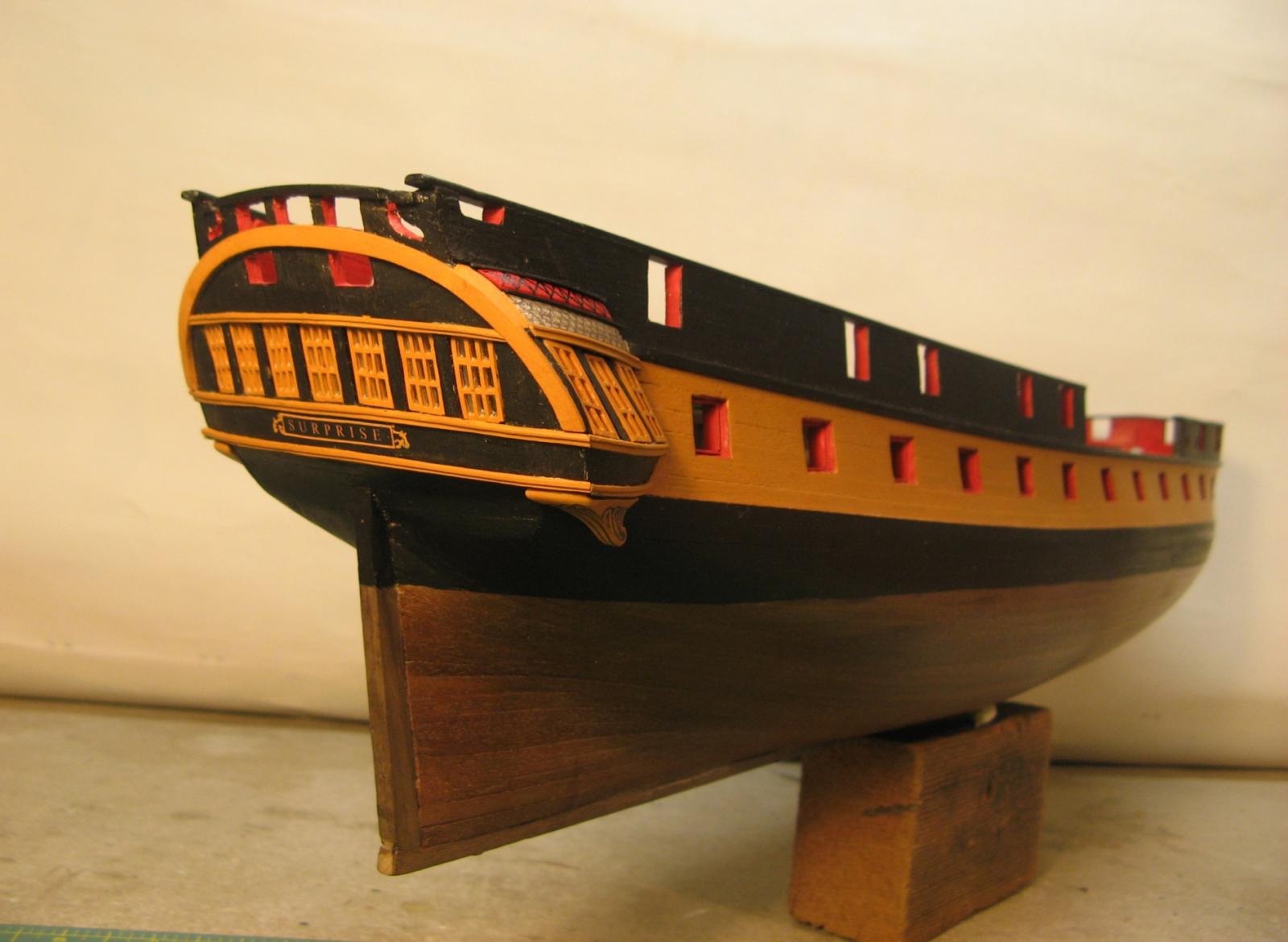
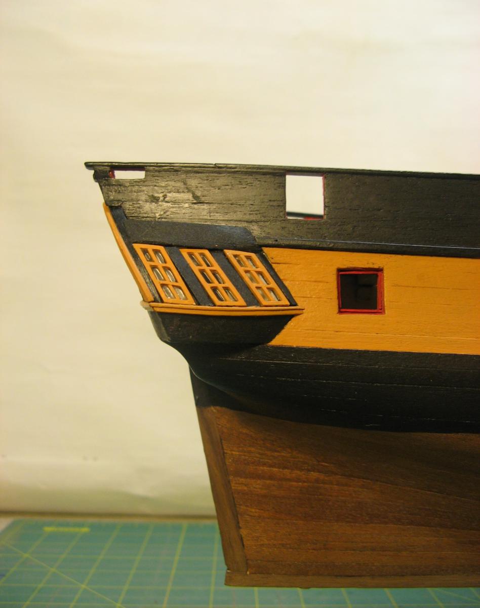
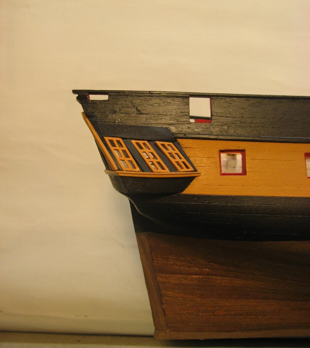
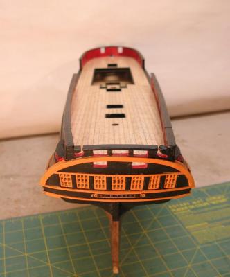
More stern details. The design of decorative elements above the quarter gallery windows took a bit of research but at the end of the day there seemed to be several different versions so I thought I might get a bit creative and create my own take on them. This bit of one of the paintings in the L & H book looked to be the most interesting so I used this as a start. This is my version: Now I can start on the bow details, all those curved elements should be interesting to create. Cheers, David.

- 256 replies
-
- 17
-
-
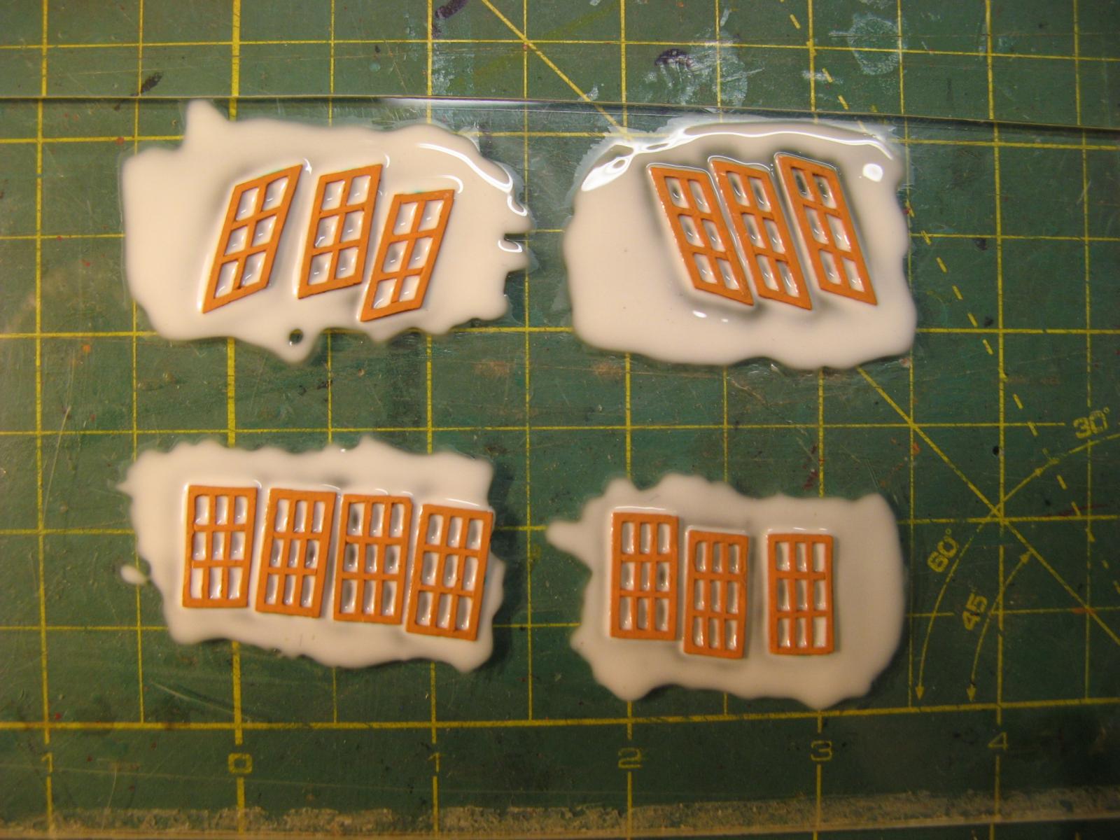
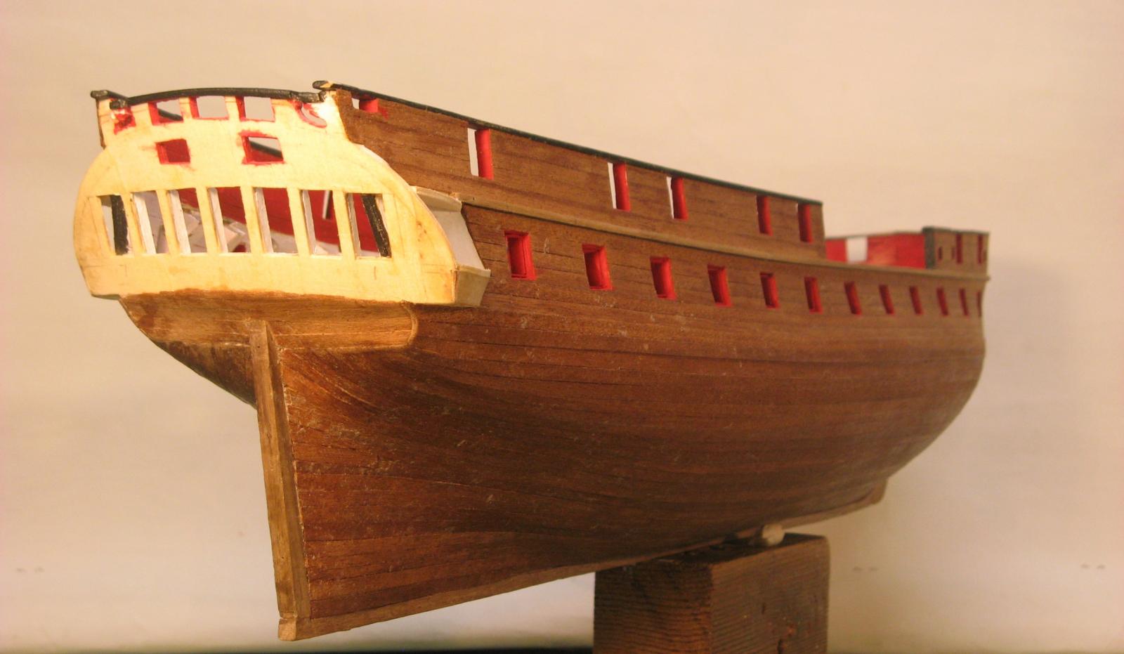
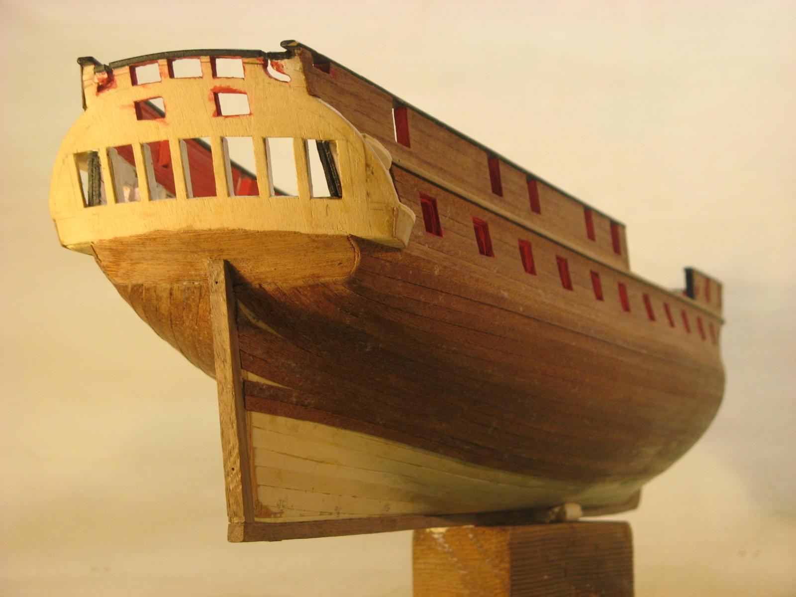
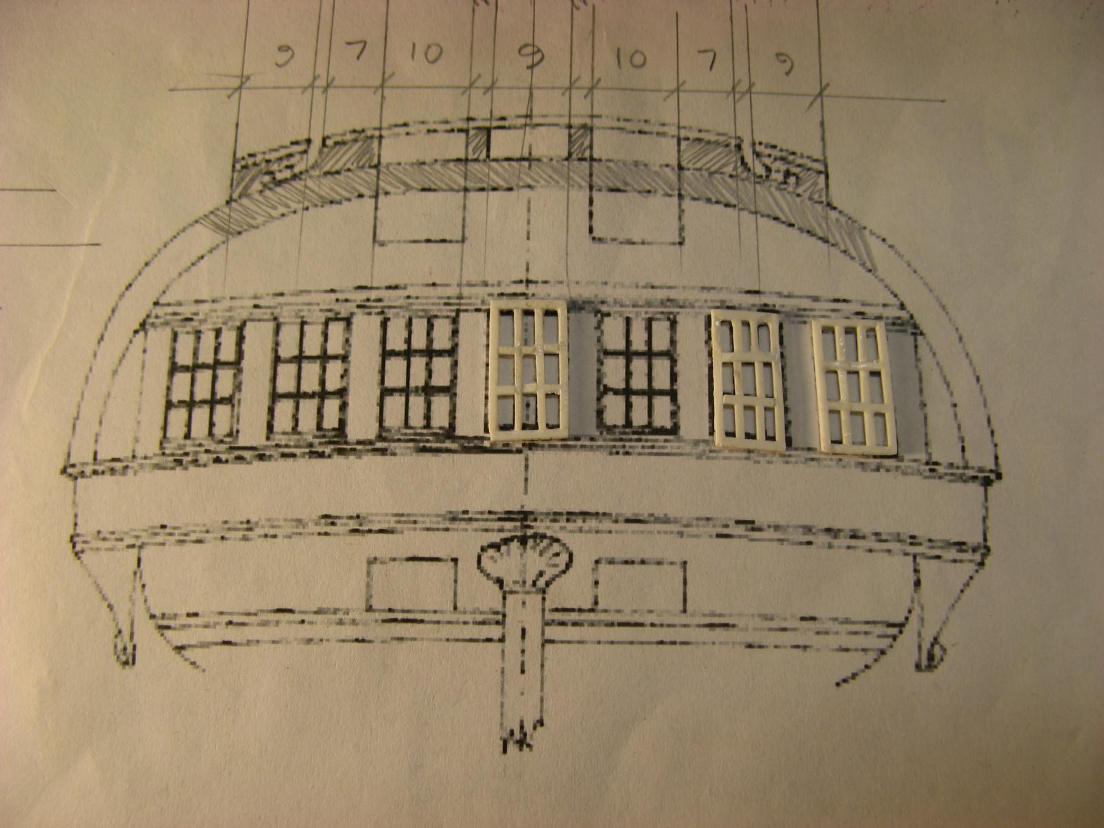
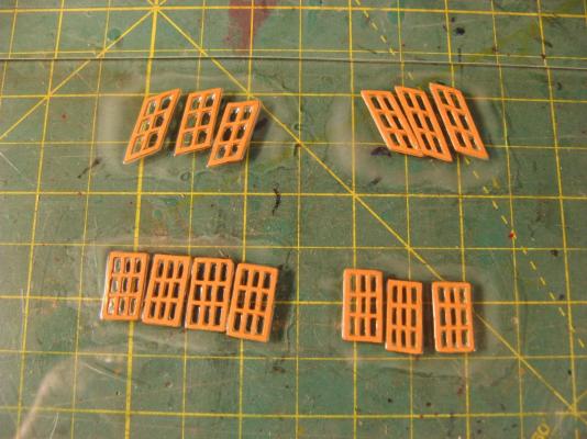
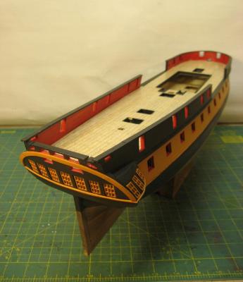
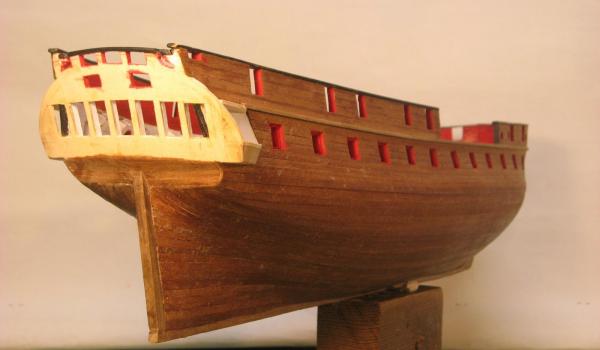
Stern windows take 2. After looking at the windows for a while I decided that I wasn't happy with the size of the inside mullions in relation to the outside frames so I cut out the mullions and replaced them with material about two thirds the thickness. I also decided to try the PVA glazing method and it worked out OK. I spread out a film of PVA on a perspex sheet and placed the window frames onto it. After the glue had set I peeled off the windows and trimmed the edges. I tried the process on a sheet of glass but the PVA stuck to the glass better than to the window frames so that did not work! Now I have glazed windows installed at the stern and can start on the rest of the stern detail. Cheers, David. Stern windows now installed Revised frames with smaller mullions Frames on wet PVA PVA dry before removing and trimming

- 256 replies
-
- 13
-
-
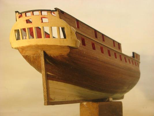
Greetings all, Back from holiday and into some stern detailing. First dry fit of windows and some of the rails and stern arch fitted. Next will be fine tuning the fit and glazing the sashes. I have done a trial on a spare sash using PVA glue spread on a piece of acrylic then window placed onto the glue and carefully peeled off and trimmed when dry. Works pretty well. Will do a few more trials on spare windows, I have a few that weren't quite the right shape, they were even worse than the latest attempts. There is still plenty of details to go on the stern. Unfortunately the drawings in Lavery and Hunt don't show much detail so I need to find other sources. Some of Geoff Hunt's paintings show details and I will be working from these. There is also the "Master & Commander" replica and pictures of various other models to refer to so some creative interpretation will be required. Cheers, David.


- 256 replies
-
- 19
-
-
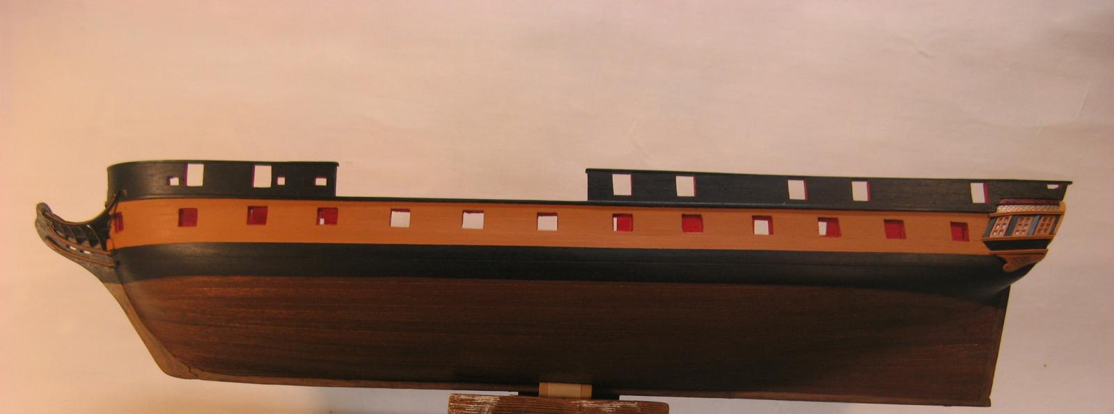
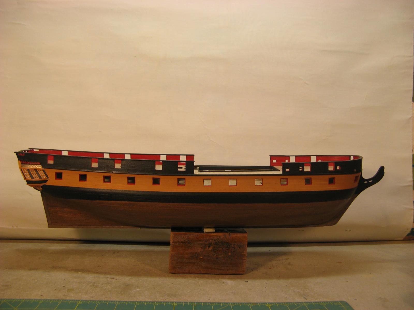
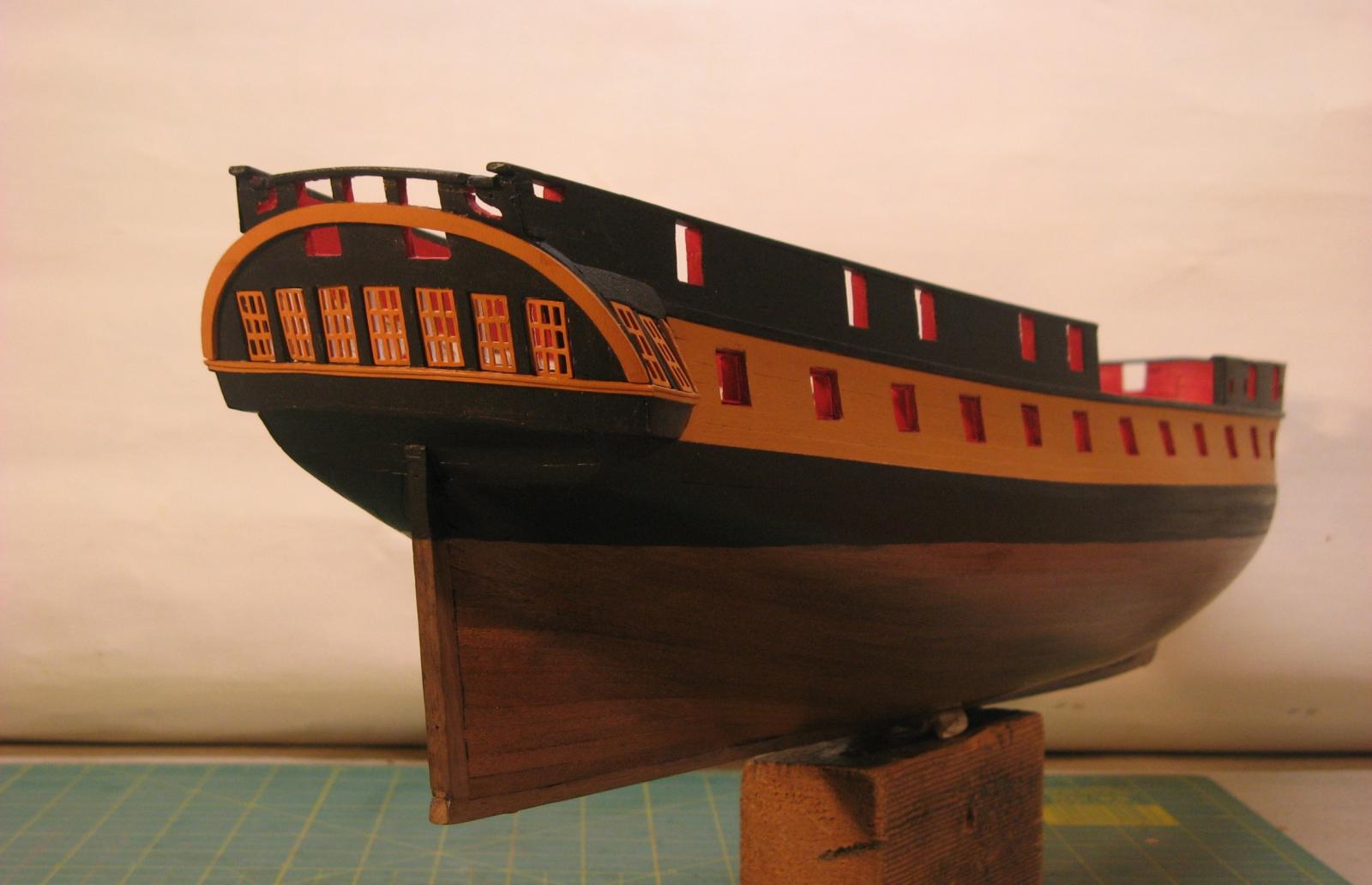
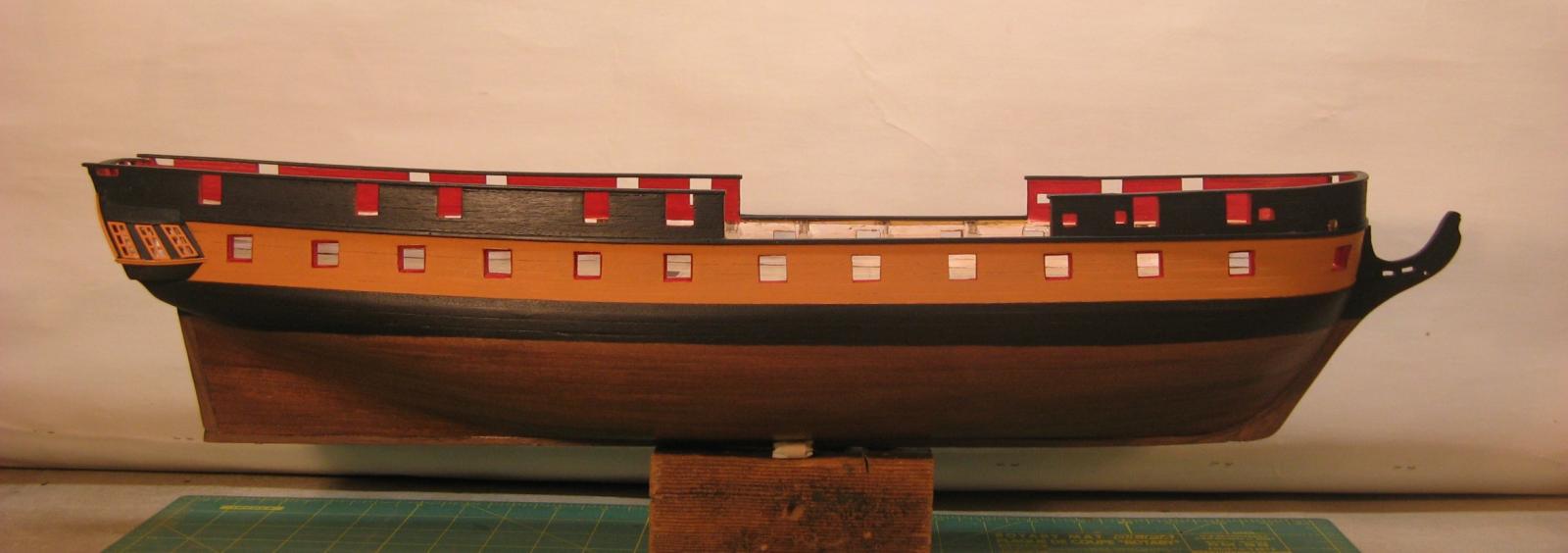
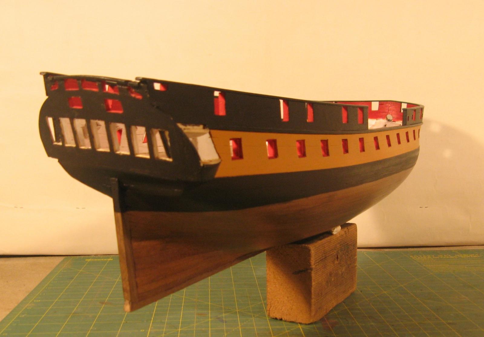
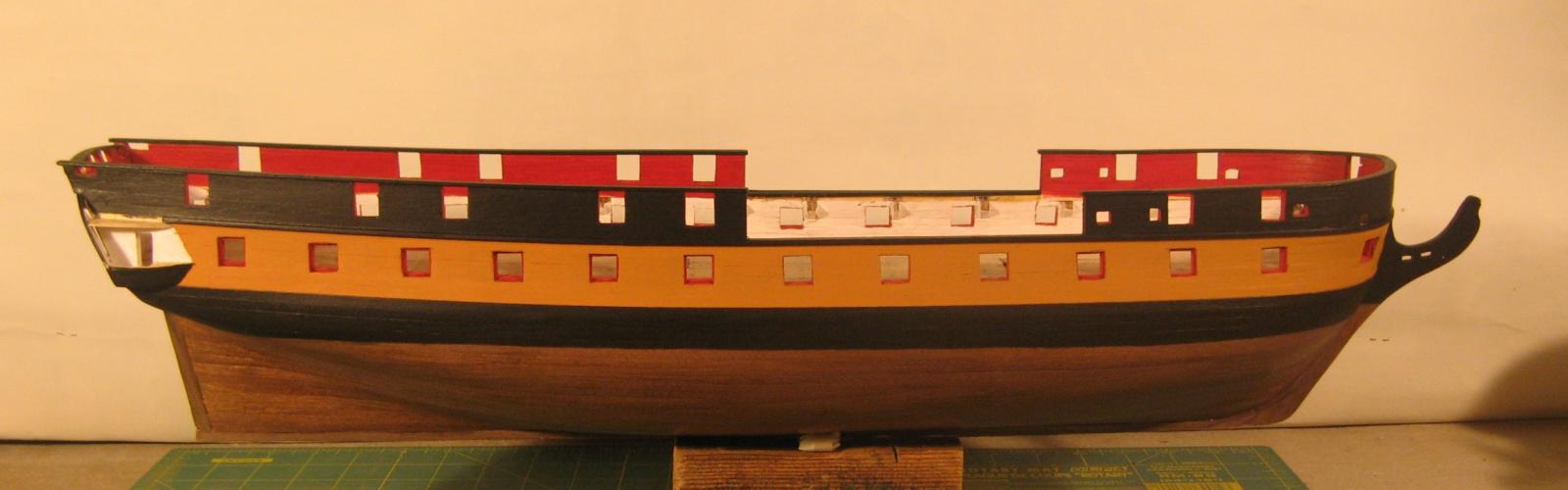
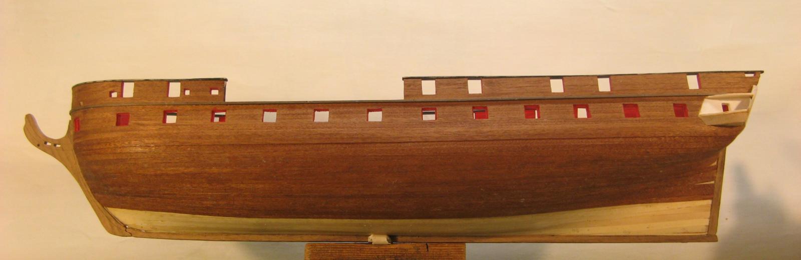
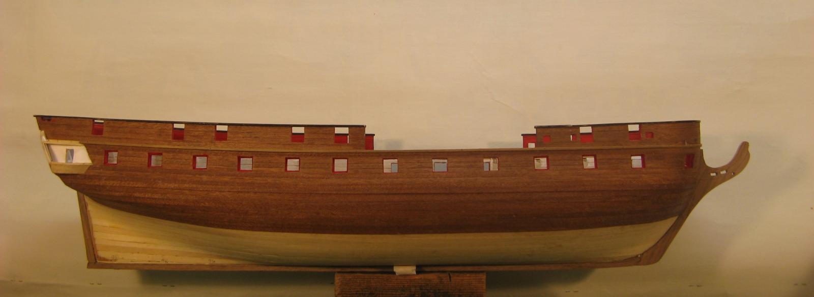
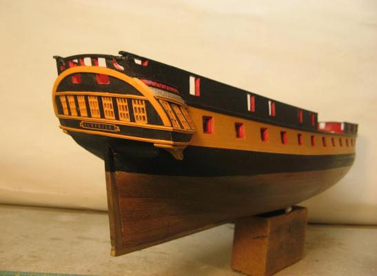
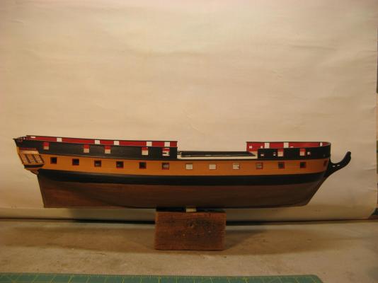
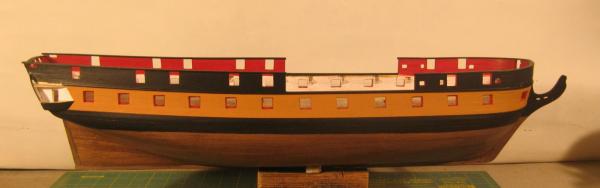
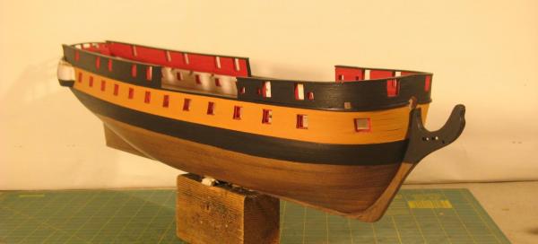
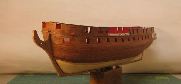
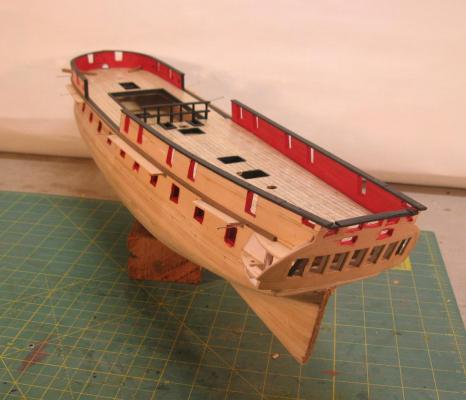
Transformation time! Some serious painting has been done and the hull is now the finished colours. The black was easy enough, Chaos Black from the Games Workshop range. I thought the yellowish colour was going to be more difficult, the more pics of replicas and other models I looked at the more options there seemed to be for this colour, ranging from almost lemon yellow to quite dark ochres. I couldn't find anything close to the colour I was looking for at any of the usual model shops so I thought I would be in for a lengthy mixing trial and error process but before starting on this I decided to give the Games Workshop another visit and found a standard colour which is exactly what I was after. Painting the black and ochre bands was relatively easy as I was working to steps in the hull planking but the waterline was a bit more of a challenge. I am quite happy with the finished look. Cheers, David.

- 256 replies
-
- 11
-
-
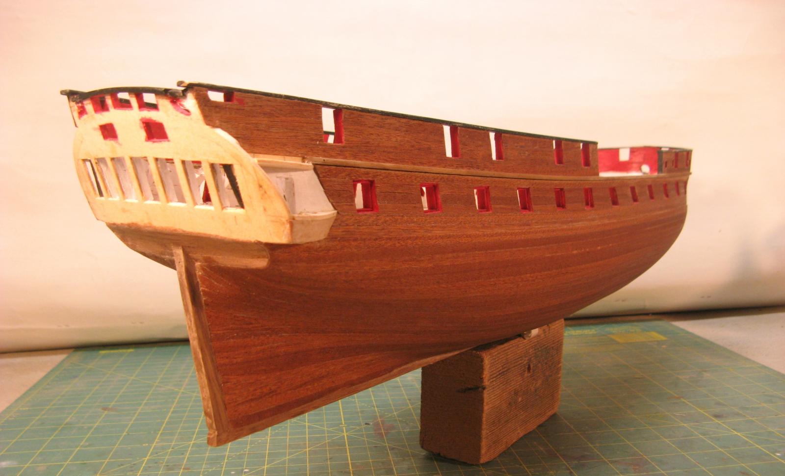
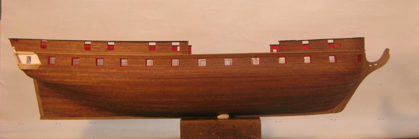
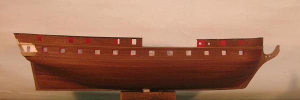
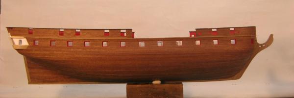
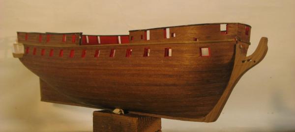
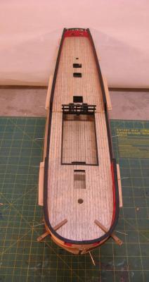
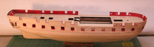
Hull planking tidied up and sanded. A few of the plank joints are a little wider than I would have liked and I have the option of some filling. However, I don't think I will fill as this may decrease the plank edge definition which I think is important to maintain so that the planked character of the hull is visible. The planking colour looks a bit patchy as the pics were taken just after wiping down with a damp cloth to remove dust and excess glue. When I took the bow shot some bits had dried. The hull below the water line will be clear finished so this is the colour I will get. I have definitely decided against coppering below the water line. After painting down to the waterline I can now start on more detailed work around the bow and stern. Cheers, David.


-
In answer to the window glazing question I haven't decided yet. I may try Janos method of puddling PVA glue onto a smooth plastic surface, placing the window frame on the spread out PVA then peeling off the plastic when set. In the past I have glued thin rigid packaging plastic to the back of the frame but I think the PVA approach may work better. To achieve a decent finish I think I would need to finish paint the window frames first. Cheers, David.
-
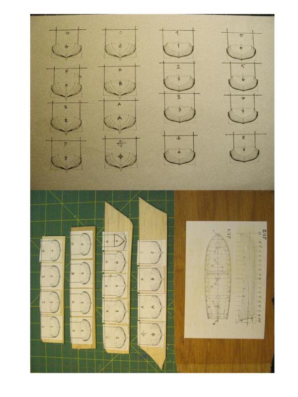
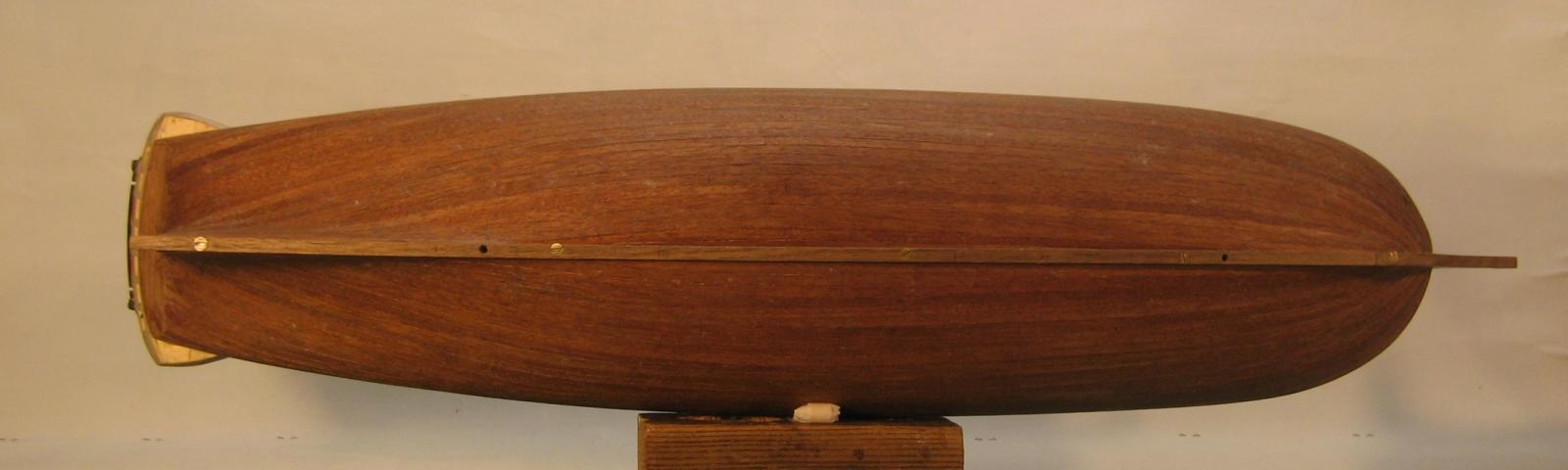
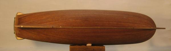
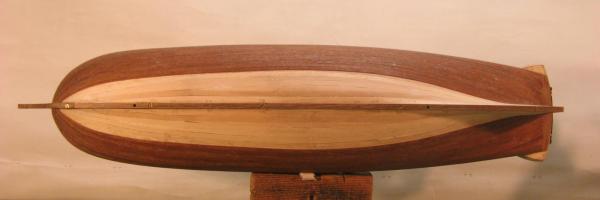
Hull planking complete! The "doing it by eye" approach seems to have worked out OK. There are 35 planks each side with 2 small stealers either side at the stern. The bow worked out with plank tapering to a minimum of 50% plank width and heat shaping to fit the 3 dimensional curved areas. Now to tidy up, a light sand, excess glue removal and some minor repairs. Cleaning up the PVA glue should be a lot easier than removing the contact adhesive of previous builds. Next some paint to above the water line. My original thought was to leave below the water line clear finish natural timber rather than attempting some sort of coppering finish and I think I will stick to this. At times the planking process got pretty strenuous, removing glue, smoothing out lumps and bumps and firmly holding down parts of planks that were reluctant to stay put, done with the hull on its side or upside down resting on the bulwarks. All this was managed without collateral damage. I'm sure this was due to the early decision to make the basic hull structure from 6mm marine ply and to build up the hull thickness so that the area above the main deck was solid and strong. As a precaution I screw fixed the keel and the cut water to ensure they wouldn't move during the planking and future build processes. The 2 holes that can be seen in the keel are for threaded rods to screw into internal captive nuts for final display. I didn't do this on my Bounty build and had no end of trouble fixing her keel to the brass display supports. No such problems this time. Cheers, David.
- 256 replies
-
- 11
-
-
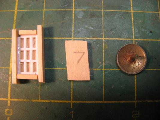
More planking progress. Now down to the last 8 planks, so far so good with the "eye ball" approach. I may yet come to grief! I have been curving the planks mainly at the bow and now more toward the stern with a soldering iron to get a shaping across the width of the planks that allows them to lie flat on the 3 dimensional hull curves. I haven't tried this before but it seems to be working. As a bit of a distraction I have been working on the stern windows. The mullion sections work out at about 0.75mm square to scale. I initially tried slicing timber but the very small section was unstable and the first attempts fell apart! I acquired some 1 mm square polystyrene rod and tried that and am encouraged by the results. So far I have made up 3 of the 7 stern windows and i think they will be OK once painted. Cheers, David. 8 planks to go 8 on one side, 9 on the other Stealers to be infilled plank curved to fit on 3 dimensional hull curves stern window shaped with plastic rod on the piece cut out from the stern stern windows so far


- 256 replies
-
- 11
-
-
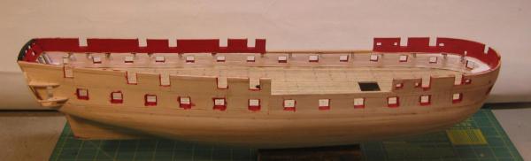
Planking progress. 20 done, 16 to go. Getting to the tricky bit now, so far I have been tapering the bow planks by 1mm at varying lengths to keep a consistent tapering difference between midships and the bow. With any luck I will be able to keep this up and not need any drop planks. The stern is a bit more complex. There is a narrowing between midships and part of the way to the sternpost than the hull flairs toward the rudder. This will need some stealers to make up the difference. Previous models have been planked using contact adhesive and the process has been a bit panicky and hurried as well as messy. This time I am using PVA, a product called Titebond which I find pretty as it has good initial grab but still allows some adjustment. This is much slower but more relaxing. I do one or maybe 2 pairs of planks at a session. Cheers, David.

- 256 replies
-
- 12
-
-
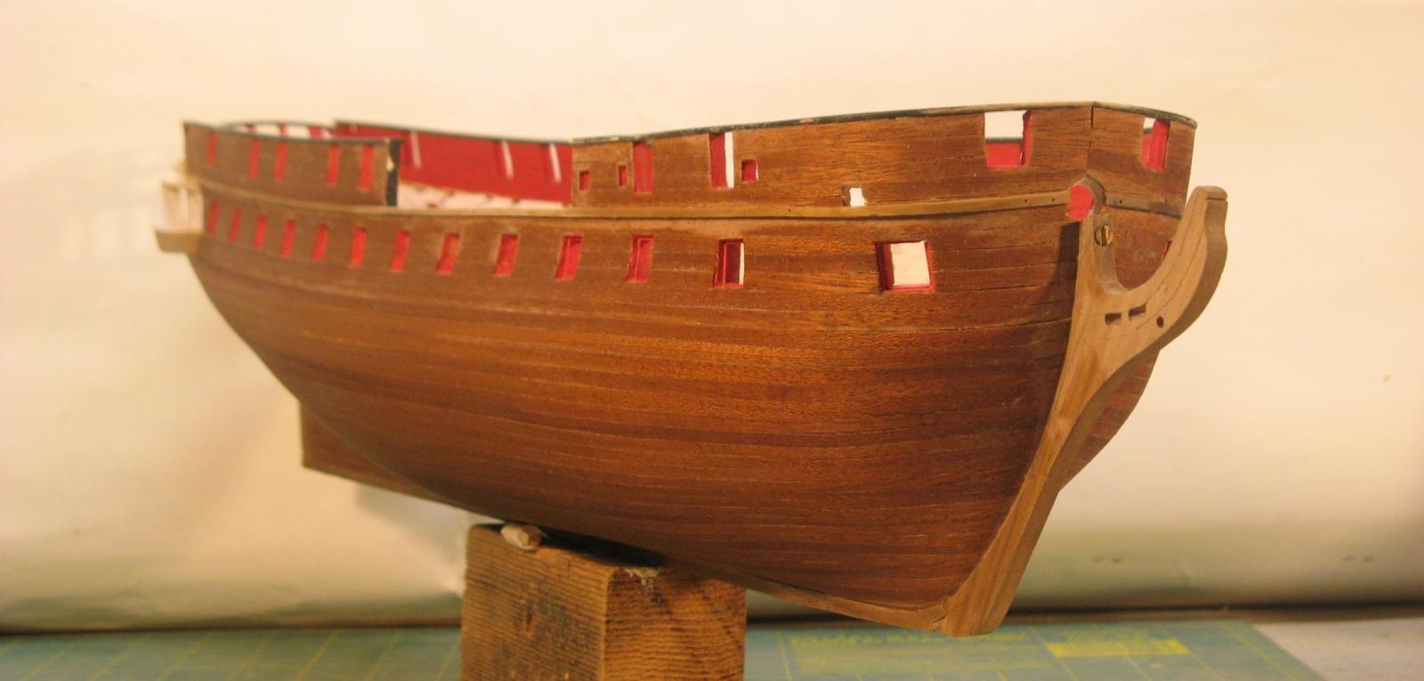
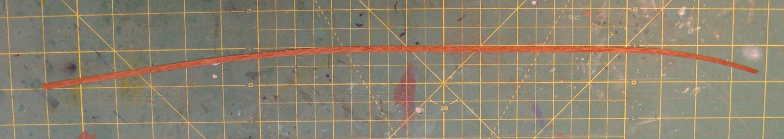
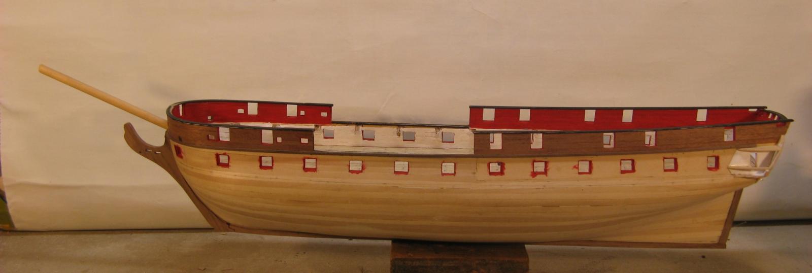
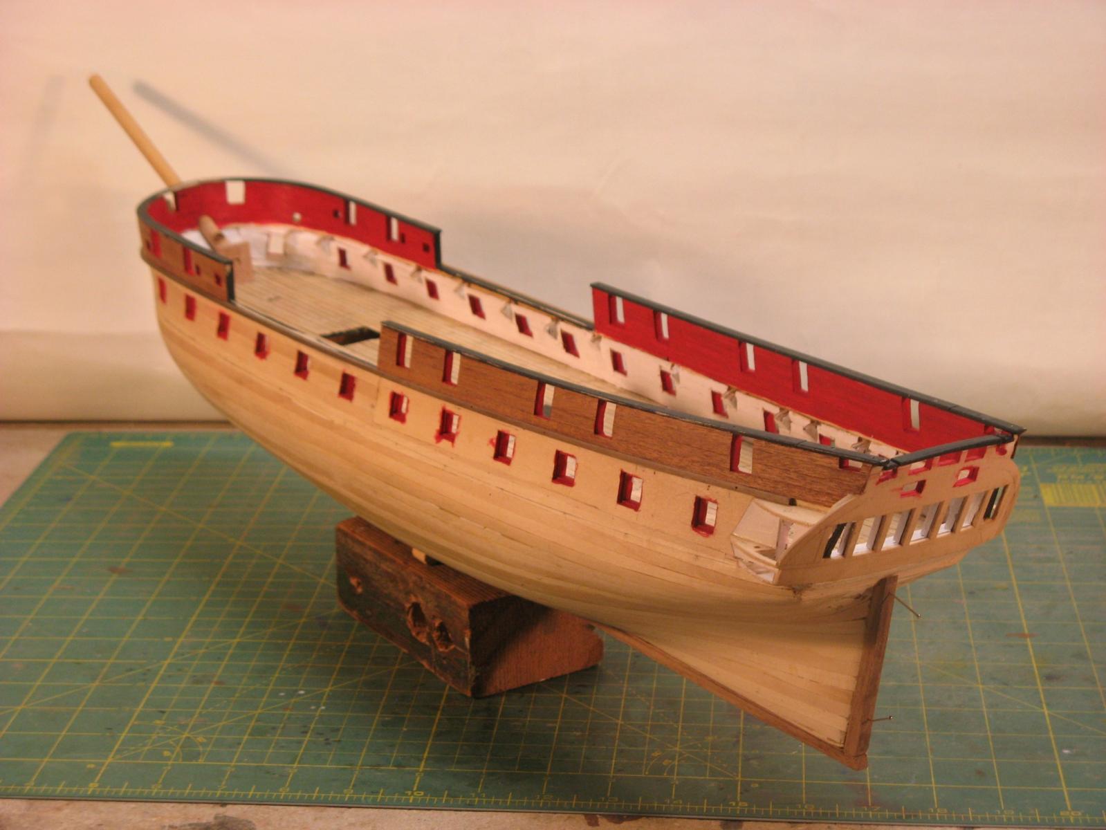
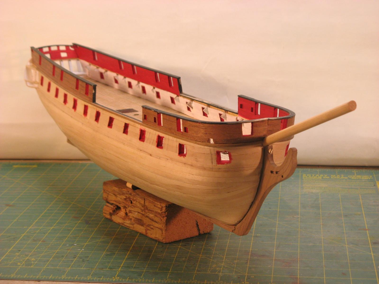
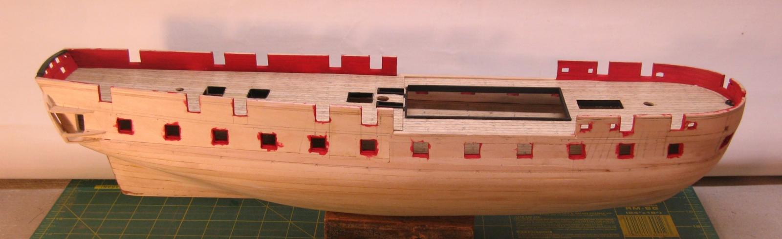
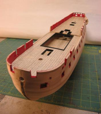
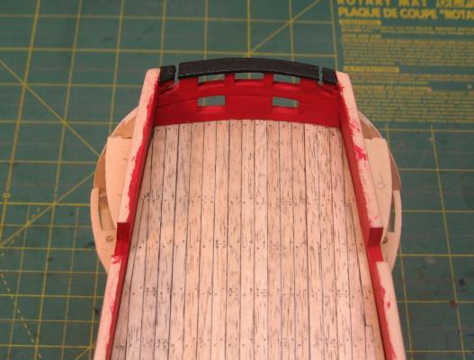
Hull progress. The hand rails to the bulwarks and the transom have been installed. The rail at the forecastle/quarterdeck level, the channels and the catheads have all been dry fitted to check relative positions and all seem to fit OK. Next step is to paint the lower rail, fix it in place and plank between it and the handrails. These will all be painted black. Before I can do any more planking below this I will need to shape and fit the cutwater, keel and probably the sternpost. Cheers, David.

- 256 replies
-
- 10
-
-
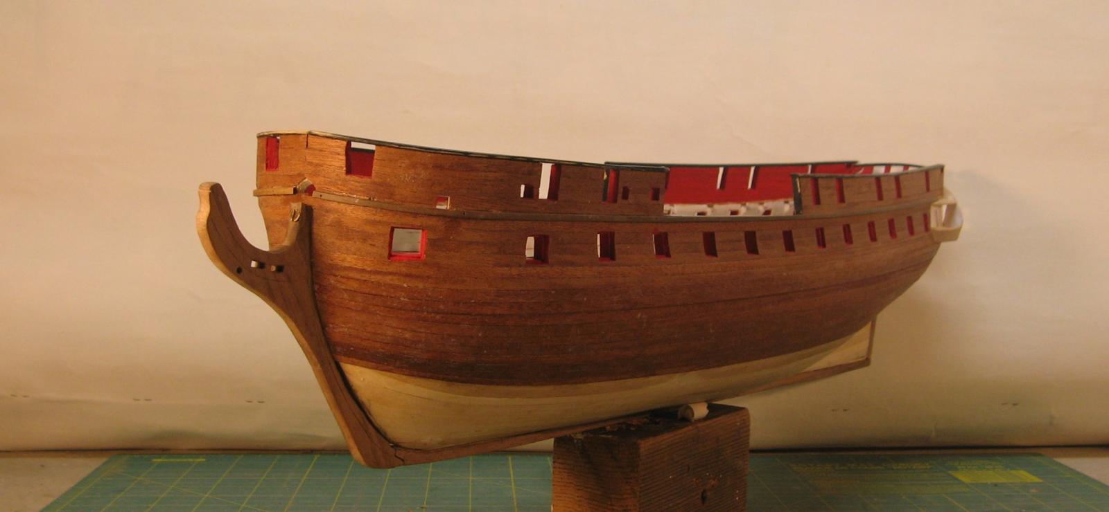
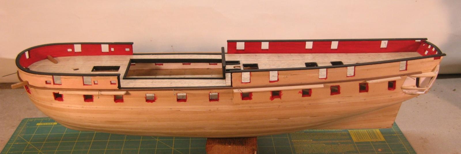
Painting has started with the hull inside done. More holes in the hull have been made towards the bows for various bollards and the stern has had some more work. The structure for the quarter galleries has been dry fitted and will be removed and refitted once the final hull planking has been done. Cheers, David. Different colours makes more sense with the deck in place The relationship between the quarter gallery parts and the decks and the rails on the hull outside took some figuring out but I think I've got it looking OK.
-
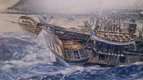
Hi Allan, The painting is by Geoff Hunt. The book I am working from is by Brian Lavery and Geoff Hunt (not Lavery & Hudson as I said above!). My son bought me a numbered edition (165 of 250) signed by both which includes a nice signed print of one of Geoff Hunt's works which shows several of Jack Aubrey's ships with Surprise in the foreground. I have it framed and hung on the wall of my study for inspiration. It shows Surprise in an odd mast configuration, the mizzen top gallant mast has been dropped. As well as lots of god info about Surprise the book has a section on Geoff Hunt's paintings including preliminary sketches and details. There is a dimensioned sketch by Hunt which I found helpful in working out mast heights. I too would love to have one of the originals. I can't imagine they would come up for sale very often. Cheers, David.