HOLIDAY DONATION DRIVE - SUPPORT MSW - DO YOUR PART TO KEEP THIS GREAT FORUM GOING! (89 donations so far out of 49,000 members - C'mon guys!)
×


AON
-
Posts
2,868 -
Joined
-
Last visited
Content Type
Profiles
Forums
Gallery
Events
Everything posted by AON
-
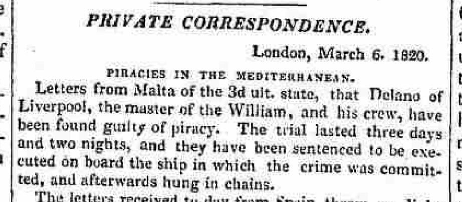
PIRATES!!!
-
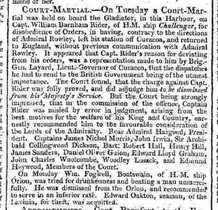
This is why they started performance reviews - 1810
-
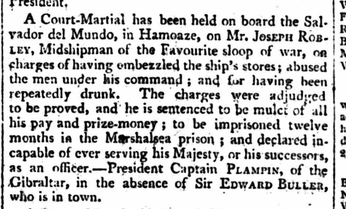
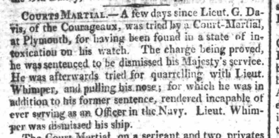
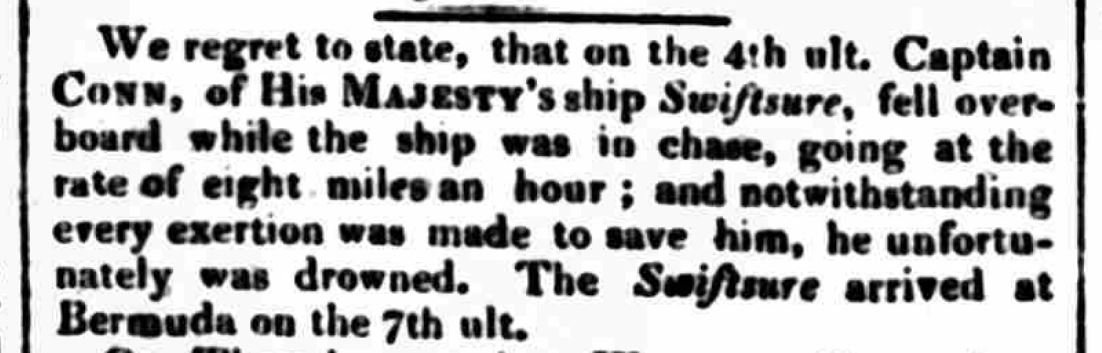
another promising career (?) cut short - 1810
-
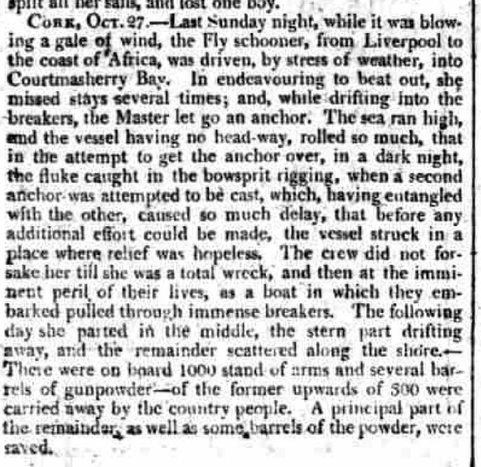
should have practised with the anchors more - 1810
-
hmmmm.... - 1810
-
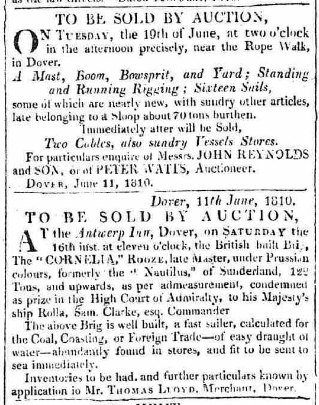
Nothing more entertaining than a good auction - 1810
-
 Regarding the rigging of the bowsprit, jib boom and yards. I had had a question about the rigging of the Jib Guy Pendant. It originates from the head of the jib boom and needs to run over top of the spritsail-topsail yard to run through a thimble on the spritsail yard. I predicted with my drawings that this pendant would run below the spritsail-topsail yard to reach the thimble which would mean it would then pass through the spritsail-topsail canvas. Search as I might I could find no image or statement to describe how the line could be taut and still pass over top of the yard. The logical solution was that the spritsail-topsail yard needed to drop, suspend lower below the jib boom to create the required clearance. My drawings showed it would need to hang a minimum of 24 inches (61 cm) below the jib boom. Two feet did not seem to be unreasonable. While reviewing a video post in HMS Bellona 1760 by SJ Sloane, posted by Hubac's Historian , posting #1670, showing how a steering wheel works on HMS Victory I spotted the rigging of the Jib Guy Pendant. It passed over the yard but is loose. I captured a screen shot of the image. If anyone else should ever ponder on so small a detail, this may be the only image you will find.
-
lost at sea? part of the story is missing... somewhat like newspaper stories today - 1810

-
I've no witty comment for these two - 1810

-
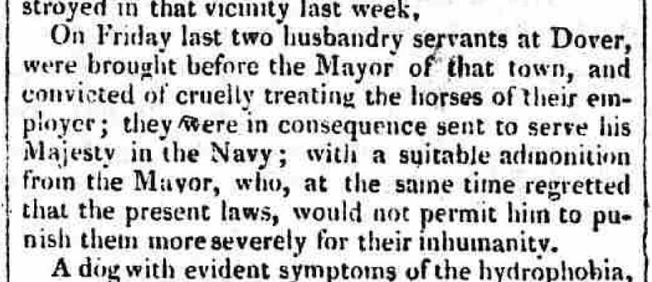
and last for today... need a job - 1810
.JPG.f690212b04e0093225972e178665cd32.JPG)
-
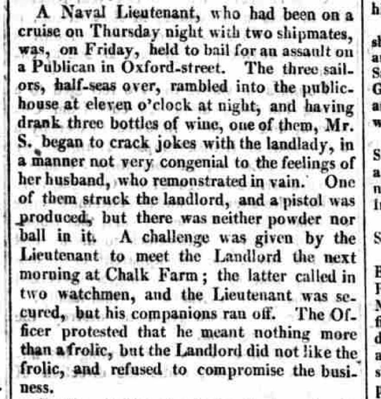
rank has its privileges - read down to the end. 1810 But sir... we was just 'av'n a friendly pint and it went down 'is wind 'ole, so I's made to smacked 'm on the back a few times to help 'm out, but he kept mov'n about on me, so's I smacked 'm to stop... honest.
-
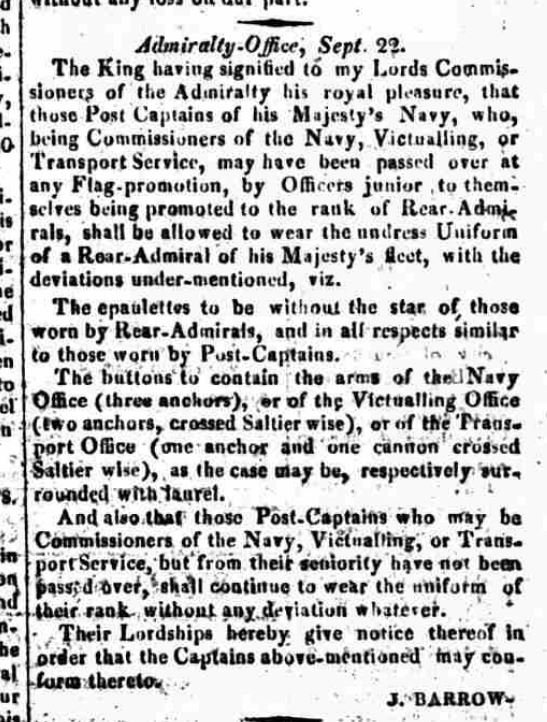
Here is one you don't see often - 1810
-
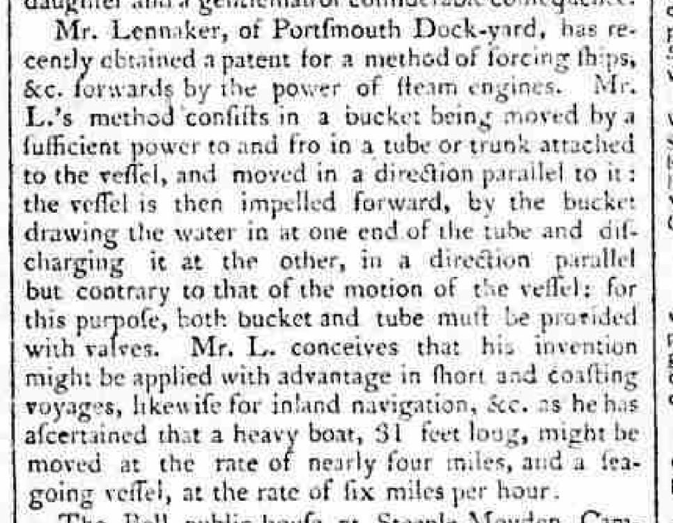
Here are a few a new invention with stem power - 1810
-
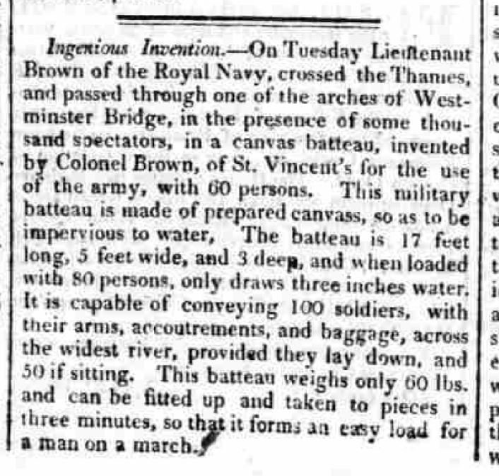
Mark It is easier to fit people in a wooden boat with thwarts than in a canvas boat that mentions them laying down in it and being stacked like cord wood
-
Mark re: the smugglers unfortunately my focus is on one ship and so I've been given individual pages that mention her articles posted here are what I find on those pages that grab my attention I see but a fraction of what was printed in the time what happened to the smugglers was likely on a page I didn't get bad news is I finished all the pages I had. good news is I've just acquired another 400+ pages the other day, so there may be more here. Alan
-
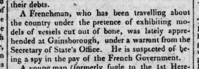
regarding the fake bone model seller: I have to re-read many post as they sometimes read funny. I think they were saying he was a fake seller of bone models. regarding the number of soldiers in the boat: it all depends how you fold them? possibly they were boy soldiers! much younger and shorter, smaller chest size.... they had arms, possibly removed their legs?? I think it is just fake news possibly to confuse the enemy as I can't get more than 27 in the space semi-comfortably, 30 otherwise.
-
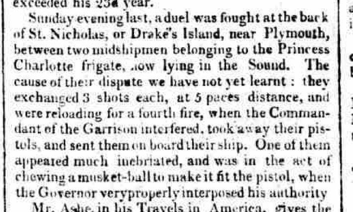
Why not just a good old fisticuffs knock down brawl? - 1809 Oh, right, unbecoming of a potential officer.
-
A collapsible! 1809
-
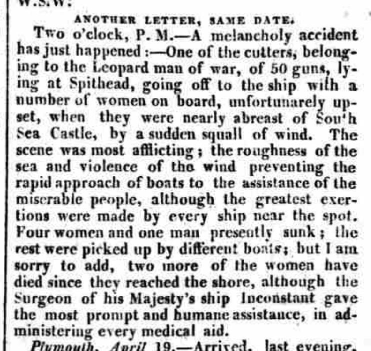
I would not want to be the one to break this news to the crew after a long voyage - 1809
-
A lesson from the past - 1809 We should be very careful!
-
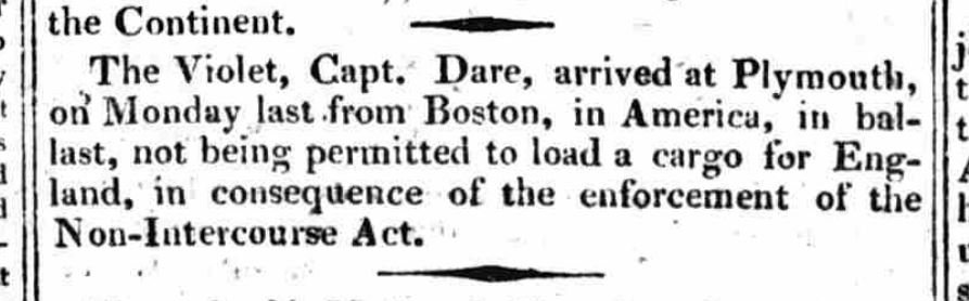
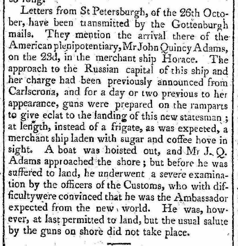
One for our American and Russian readers - 25 Nov 1809
-
of all the articles I've scanned through (1012 to be exact) this is the very first in which I've noticed the use of the acronym "HMS".
-
"half seas over" means fairly drunk or on they way to be stinking drunk... similar to "two" or "three sheets to the wind".
-
same paper.... and the answer is a resounding NO, they will never learn.
-
will those sailors ever learn? 1808 (FYI - I've read many articles about duels... one between two women over a man! and the one was quite a good shot)