HOLIDAY DONATION DRIVE - SUPPORT MSW - DO YOUR PART TO KEEP THIS GREAT FORUM GOING! (89 donations so far out of 49,000 members - C'mon guys!)
×


AON
-
Posts
2,866 -
Joined
-
Last visited
Content Type
Profiles
Forums
Gallery
Events
Everything posted by AON
-
 Mark, thank you for the vote of confidence. I will refer to it the next time I am in doubt (which is often). I made an error in my post, corrected it and added a note identifying it. (Horizontal, horizontal, horizontal, .......... ad nauseam ) I admit I was aware of the collar beam, and so possibly should have added it to the list, but I suspect the bowsprit passes clearly under it as it might be difficult to install if it didn't. I'll be copying your photo if you don't mind.
 -
I tend to believe they did not for this "horizontal" mast as with everything I've seen (looked at) in the last couple of years did not seem to indicate any such bracing. ("correction": I originally referred to this as a vertical mast which was an error on my part. Now I need to get a brain tuneup) I imagine that between locking the foot in place in it's step, the gammoning bindings, and the bowsprit shrouds, it t'weren't go'in nowhere. Waiting to read what the more experienced modellers have to say... as I am unfortunately not one of those.
-
OMG. I never thought of it like that. That makes Her Majesty, Queen Elizabeth, the !st of Canada. Somehow I find it hard to believe a whole nation got it wrong. But then again, being the good docile child nation, possibly we don't really care about the number. Sorry Mum.
-
great use of elastic bands. I find I either haven't enough or they are too short. I am also always worried the "timber" (sliver of wood) I am binding back to will snap off
- 34 replies
-
- 2
-

-
- grand banks dory
- bluejacket shipcrafters
- (and 1 more)
-
It is done and my vision is amazing. Everything is so much brighter now. I will likely need weak reading glasses and am presently using my shop safety glasses that have +1.5 magnification. I was using the pair with +2.5 magnification the other day. (Neither of these worked for me at all when my son gave them to me a year ago) I am itching to get back in the shop, and the weather is not cooperating, it was sunny and warm yesterday. It will be difficult to chose the basement over the outdoors in about 2 weeks when the doctor gives me the "all clear".
-
I've completed my spreadsheet tally of 879 blocks (standing and running rigging, less those in the boats) as at this time I believe I will include furled sails. This includes what we normally think of a blocks, plus parrels, hearts and dead eyes. My reference is Steels Rigging Tables for a 74 gun ship. I've considered all sizes from 5" to 56" and the incremental differences at 1:64 scale. As it will likely be difficult to finish sanding a block shape to "exact scale" I believe I would group them so three consecutive sizes (5", 6" , 7") would be one size block (6") as the difference at 1:64 scale is extremely minimal. I would aim for the middle in any one group and have made a note to remind me of this. I just have to remember where the note is... or that there is a note! This gives me 2 sizes of hearts (16" and 25") , 10 sizes of blocks (6", 9", 12", 15", 18", 21", 25", 28", 38" and 56") and 3 sizes of dead eyes (7-1/2", 11" and 17"). I go to get my other eye done this Friday, and three or four weeks later I will be able to go back down to my shop and get working on the square frames, and some blocks for the two yards I've made for the bowsprit and jib boom masts.
-
I still refer back to the article where they scrapped off layers of paint to reveal the original colours, then look at the various paintings. But the original point was the number of pillars, single row or set of two rows. We've digressed on Marks build. Sorry for that Mark. Possibly this might be an excellent separate discussion elsewhere?
-
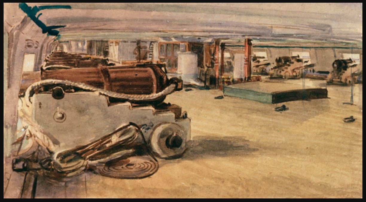
HMS Bellerophon Gun Deck water colour, date unknown National Maritime Museum, Greenwich, London https://collections.rmg.co.uk/collections/objects/110266.html
-
Ahhh, but the article states they removed layers upon layers of paint to discover the Orlop deck painted a creamy stone colour, the surgeon's cabin "a grand two shades of blue", and the admiral and Captain's cabin a light blue. So is it not very likely the gun deck was painted something lighter, rather than blood red?
-
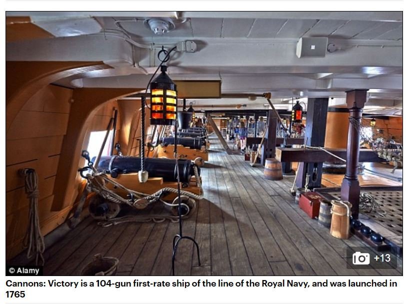
Druxey Below is the image of HMS Victory in 1765 (ref: https://www.dailymail.co.uk/news/article-2583165/Nelsons-flagship-HMS-Victory-true-colours-blue-deck-none-hideous-orange.html). I am looking for the source of the Bellerophon painting above but suspect it is in early service.
-
In this painting of HMS Bellerophon's gun deck there seem to be a pair of pillars
-
On my plans some are aligned with those above and others are not. I've not looked at pillars... something worth keeping an eye out for as I'm thumbing through stuff for the next few weeks.... unless your "friend" notices it first.
-
Good morning (evening) I find what you've done to the figurehead to be amazing! Very nice job. It is too bad they didn't provide something representative of the original figurehead with the kit as it must have been very impressive as described (Bellerophon mounted on Pegasus with his Javelin). The size of the 3D printed gun barrels poking out the gun ports look much better also. I am so glad you are back.
- 126 replies
-
- 1
-
-
- victory models
- amati
- (and 2 more)
-
Welcome back Mitsuaki-san! I had found your last build quite a few years ago and found it to be very educational. I look forward to following your future posts.
- 126 replies
-
- 1
-
-
- victory models
- amati
- (and 2 more)
-
You rare absolutely correct about the physical size difference at reduced scale. I'm thinking there might simply be small, medium and large. What they will be has yet to be decided. I'm tallying up all the sizes today to see what there is.
-
I noted that a word in my post above was replaced with **** the word is the actual term used to describe the bottom or tail end of the block in my opinion it is not vulgar or inappropriate for this forum. Much better than what a back splice was AKA, or a seaman's duffle bag was AKA. so the word is a r s e was that so bad?
-
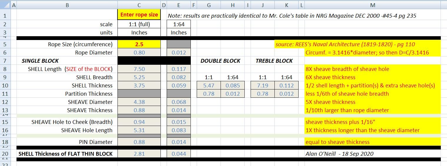
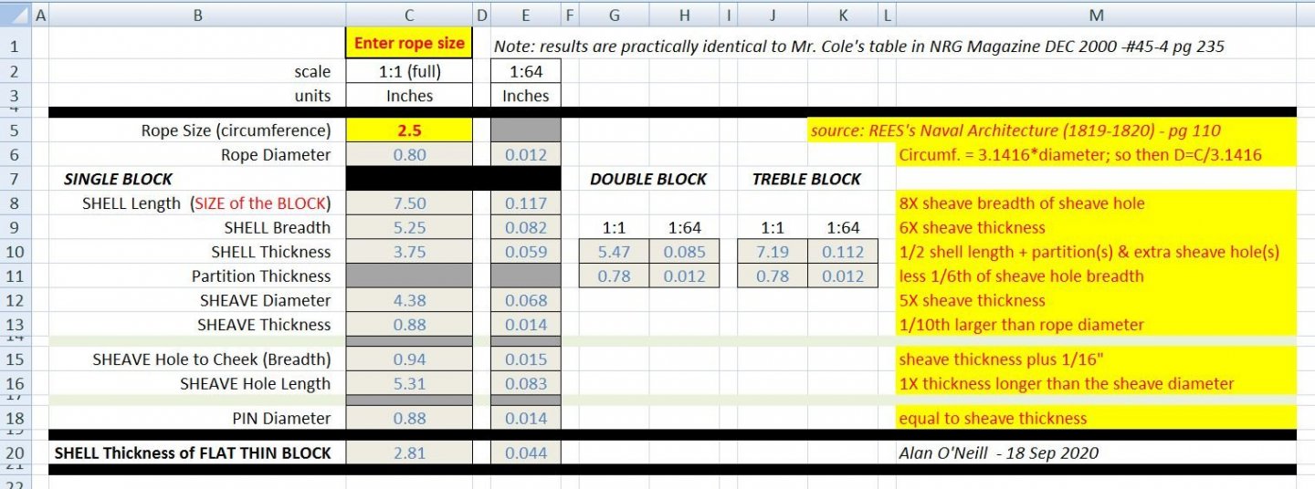
Rope blocks are said to be sized for the size of the rope. The size of the rope specified in Steel's / Rees's tables is the circumference and must be divided by the mathematical constant PI or π (3.1416). So a 2-1/2" rope is actually closer to 3/4" diameter. But, rope block sizes as listed is actually the length of the cheek (side) of the block from the head (top) to the **** (bottom). So a 10 inch block would measure nearest 10 inches tall. Steels (and Rees) provide ratio rule of thumb guide to calculating the dimensions of the various size of block shell and shiver (sheave) as determined by the size of rope (see my spreadsheet mentioned in the post above) While working with my spreadsheet I'd noticed a discrepancy between the ratio rule of thumb and the rigging tables, and have been trying to understand why they differ. The tables specify 10" and 9" blocks for 2-1/2" rope whereas the ratio suggests the length of the block should be 7-1/2" ( of rounded up to 8"). I've noted this same thing happening for other size blocks throughout the rigging tables. I should also point out I am not the first to mention this, Mark, SJSloane mentioned this in his build of HMS Bellona. After a day of searching and postulating I've noted the physical difference between 2-1/2" and 3" rope is quite minimal at about 0.8" and 0.9" diameter. 3-1/2" rope is 1.1" diameter.. So what might be called for via the "rule of thumb" for the carpenters to make blocks would not necessarily be what the Navy preferred. Which is pretty well what Druxey suggested. Then again, a rule of thumb is exactly that. So, when the time comes, I will be using sizes as specified in the rigging tables, with dimensions meant to match the block size, not the rope size.
-
while I wait for the other eye to be done I decided to look at rope blocks. I made an excel spreadsheet based on Steels' (and Rees') rule of thumb ratio. It is below to download if you are interested. The worksheet is "protected" meaning you can only enter the rope size (circumference) in the one yellow highlighted cell. All others are locked. If you want to fool around with the locked cells right pick on the labelled sheet tab (at the bottom) and a pop up menu will appear. Pick UNPROTECT SHEET and it is ready. Steel + Rees - block size calculator - rule of thumb ratio.xlsx
-
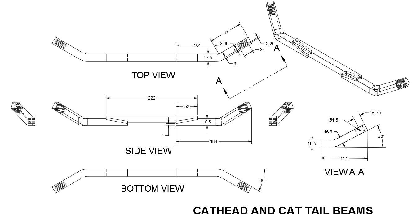
i SHOULD BE AS PICKY ALSO! I will never forget helm port. It is up there with capsize (at 12 years old while just having joined sea cadets, one fellow answered 6-7/8" to the question : what does capsize mean) I've one last drawing for now. The cat head and cat tail. The contract gives some dimensions for the pieces. Rees's plates offer some views of the items and shiver (sheave) size guide based on rope size. So does Falconer. Steele's tables offers info on the rope size. One table suggests 5-1/2" (circumference) and another 6". I've learned that at 1:64 scale the differences do not matter much.
-
As soon as Druxey corrected me I was brought back in my mind to grade school and the teacher assigning us homework to print the new words in our lesson book 50 times and she would check that it was in fact done the next morning. I think I'm gonna need a bigger pencil.
-
helm port, Helm Port, Helm Port, HELM port, HELM PORT, helm port, Helm Port, Helm Port, HELM port, HELM PORT, helm port, Helm Port, Helm Port, HELM port, HELM PORT, helm port, Helm Port, Helm Port, HELM port, HELM PORT ( = rudder hole)
-
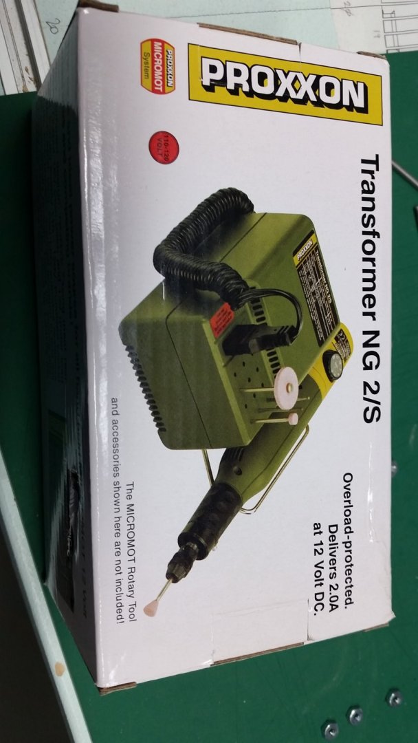
Paul I hope the pipe insulation idea works for you. It is cheap option if you've got the item laying around the house. I have since purchased a Proxon electric sander and transformer... but that is a considerable expense for one small well.
- 87 replies
-
- 2
-
-
- bluejacket shipcrafters
- red baron
- (and 3 more)
-
Good evening Paul, I detest sanding. I mean, I start with all the best intentions, with real honest ambitious resolve.... but sometimes it just never seems to end. It just goes on, and on, and... I find you just have to stick with it and tune into a radio station with some good music you can get lost in. I also experiment with all kinds of different backers for sand paper, including a small cut off length of pipe insulation foam tube. It is similar to those noodles kids use in the swimming pool. I stick the paper into the slot, wrap it around the round pipe insulation and grip it as best as I can... then get back to work. It will form to quite a few odd shapes and is forgiving to the grip. Alan
- 87 replies
-
- 3
-
-
- bluejacket shipcrafters
- red baron
- (and 3 more)
-
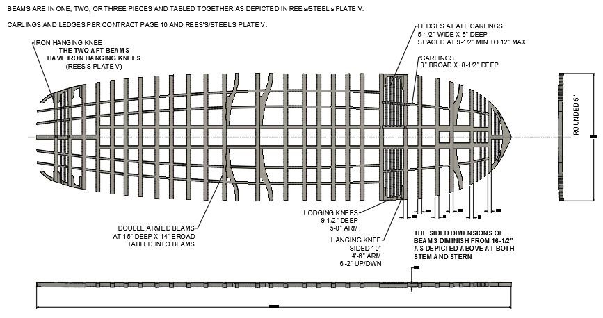
Updated the image of the Upper Deck Beams in post #1096 dated September 5. Below is the Gun Deck Beam image. I will not be doing the Orlop deck as it will not be seen very well. The five beams at the Waist will be made insitu following the Quarter Deck rounding at 8-1/2" (0.133" at 1:64 build scale). Mark: FYI - my upper deck NMM plan shaped tiller hole allows 30° of travel in each direction
-
That energy has to go somewhere as no one has yet repealed Newton's third law: for every action (force) in nature there is an equal and opposite reaction