
HOLIDAY DONATION DRIVE - SUPPORT MSW - DO YOUR PART TO KEEP THIS GREAT FORUM GOING! (89 donations so far out of 49,000 members - C'mon guys!)
×


AON
-
Posts
2,866 -
Joined
-
Last visited
Content Type
Profiles
Forums
Gallery
Events
Everything posted by AON
-
Long clamps with soft springs? If you have some spring loaded wooden clothes pins, take the spring off and try making a longer version of clothes pin from scrap wood! Hope to see your log soon. Alan
-
 Damn, and I just found your log. Sorry to read about your health issues. Hope all is well and you recover soon. Alan
- 5 replies
-
- 2
-

-
- americas cup
- endeavour
- (and 1 more)
-
It may have been bees wax to get rid of the stray wild fibres. I do not know how to tell for sure. Possibly some others might know. I take it you are attempting to clean the model. I know there are people here that have done that and I suspect they do not use Murphy's Oil Soap but rather saliva on the end of a Q-tip to remove dirt and dust. It is long and arduous work but I am told is a better way. Possibly someone more skilled can confirm. Alan
-
Good morning Mark. Yes that might have been a possibility except the timber body outline is from slicing the 3D model and then the centerline was sketched in, followed by the chocks and scarph joints on one side, then mirrored. So if my centerline was off the mirrored items would not have fallen inside the frame outline but rather crossing to be outside of it, and I hope I would have spotted that. What is as bad as having traced this onto a piece of wood and cutting it out and not noticing, I keep a log of my builds and bind them into a book for myself. I snipped an image of frames off my drawing and copied it into my log quite some time ago. It just so happens it was this frame and it's mate. I didn't notice it then either! I must have sketched it once wrong, made the correction on the other side and then didn't delete the original and mirror the proper. It is the only thing that makes sense. I worked for someone whose favourite saying was "it is what it is". I argued "it is what you make it, and if you choose not to change the outcome, then you choose what it is".... I choose this to be correct.
-
Nails and Glue
AON replied to Neil10's topic in Building, Framing, Planking and plating a ships hull and deck
I am eager to read what others might say regarding CA so I am following this thread. regarding deck planking nails. What era/type build are you working on as some nails were in countersunk holes and wood plugs driven in above them. I've read some people simply use a sharp pencil to leave a graphite dot... as an old draughtsman I always smugged my lines so I wouldn't do this. You might try it on a piece of scrap then test with a layer of poly. I've also seen black monofilament fishing line glued into drilled pockets to simulate the bolt. I am doing this on my frames and I draw the fishing line through sand paper to rough it up so the glue will grip. This is a lot more work than a pencil dot. -
you might try this https://anyconv.com/jpg-to-dwg-converter/ I've not used it and have no idea if it is any good Maybe you can post a review?
-
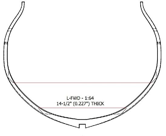
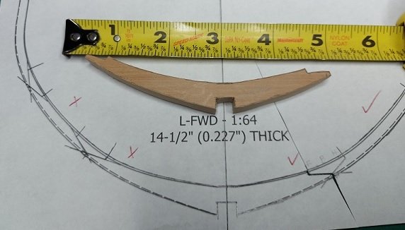
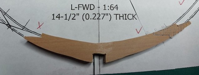
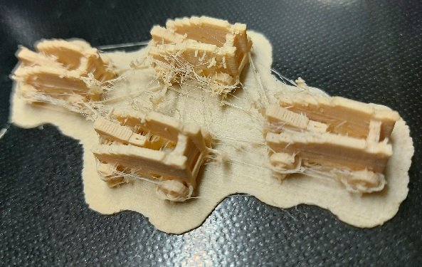
The weather is beautiful and the leaves are falling.... six bags filled from raking, and the grass is cut for the last time this year. I am just this moment printing the last set of four gun carriages. They will need to be cleaned up but I will wait until my next eye needle on December 1st as I won't be down in the shop for a few days afterwards. Today I discovered something that defies explanation. The printed template for the floor of my frame L-Forward is too long on one side. But the PDF of the drawing from which they should have been printed is correct as you can see in the images below. This suggests I supplied the wrong PDF to the printer. I cannot understand how the template was made wrong as the sketch on the 3D model was drawn on one side and mirrored to the other side, plus the original PDF is correct! Definitely a head scratcher. The above image is from the PDF and is correct. I added the red lines to show the proper alignment from port to starboard. Here you can see the incorrect floor (one side longer than the other) with the piece cut out from a tracing. How could I not have seen this earlier??? I've traced the correct location onto the floor and will cut it back. Luckily I traced the 1st futtock from the proper side of the template so they are cut correctly.
-
Sorry but I cannot comment on whether spraying with anything to protect from scratches is a good idea or not.
- 87 replies
-
- 2
-
-
- bluejacket shipcrafters
- red baron
- (and 3 more)
-
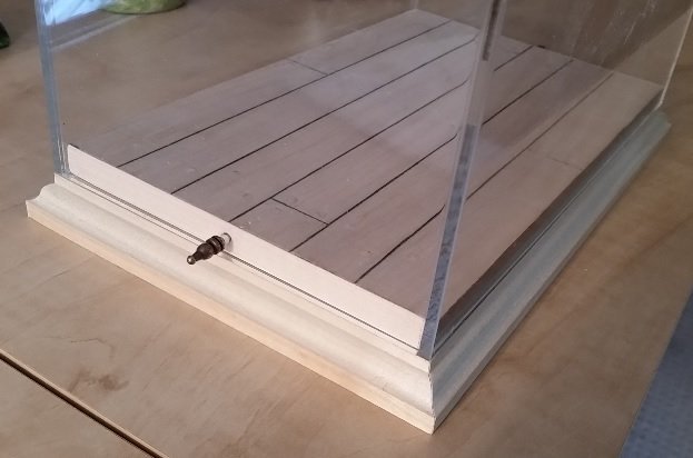
Will you be building a case for it to keep the dust off and prying little fingers away? If you do I made my base and had the acrylic cover made locally. Unfortunately I did not have the foresight to give them the base so their part did not fit snuggly so I needed to make adjustments to my base. I also added a locking pin on each end through the acrylic into the wooden base so if someone picked up the display case by the "glass" it did not fall apart. I used ornamental pins cut from kitchen cabinet hinges (bought for the purpose, not taken from the kitchen cabinet) for this task.
- 87 replies
-
- 7
-
-
- bluejacket shipcrafters
- red baron
- (and 3 more)
-
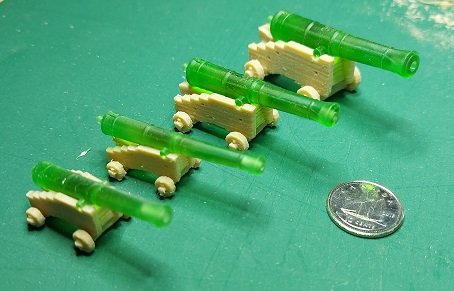
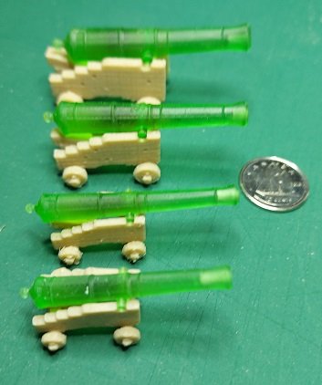
Here are the three sizes of carriages with the four sizes of guns in place. They fit quite nicely without any fiddling and fudging. Gundeck: 28 each x 32 Pdrs (9'-6" long cannon) Upper Deck: 28 each x 18 Pdrs (9'-0" long cannon) Quarterdeck: 14 each x 9 Pdrs - Short (7'-6" long cannon) Forecastle: 4 each x 9 Pdrs - Long (8'-6" long cannon) They have been cleaned up slightly with pliers, scalpel, and a finger nail file. I am awaiting the delivery of a new set of needle files so I can do a better job of it.
-
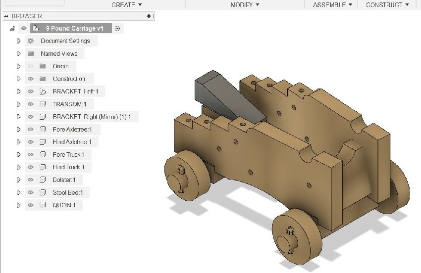
here you can see the build components in the Fusion 360 model
-
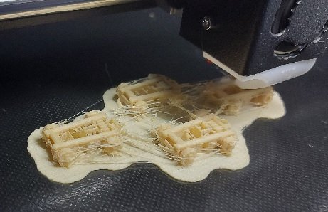
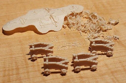
Yes that is an option if individual components will not print properly. I created the model in components so I would have that option but it was not the problem. The printer has sensors that alarm if it runs out of filament but not if the filament stops moving or feeding. My problem was that nozzle clogged. I installed a 0.4 mm nozzle and all four carriages were printed successfully. The trucks (wheels) are a more perfect circle so I will stick with this size. I've made 3D models for the other two size carriages and will print out one of each and fit them with a cannon before I print out all 28 of each. Here is the result of yesterdays success. They need more cleaning up but you can see how they turned out. The slightly larger nozzle uses more material so the cost increased from 16 cents for 4 to 18 cents for for... still quite cheap.
-
IMHO If you are not happy now, think of how it will eat at you for the next 20 years. If it is truly a learning lesson what is to be lost by taking it off and trying again. Only lesson learnt is by doing it over until you're satisfied. If something gets damaged, do that over too. You will be glad you did... eventually. I was so reluctant to remove items... now I don't think twice about it...but it did hurt the first few times.
- 87 replies
-
- 8
-
-
- bluejacket shipcrafters
- red baron
- (and 3 more)
-
the things I learn here....
-
after getting half way done my print failed yesterday. will try again later today
-
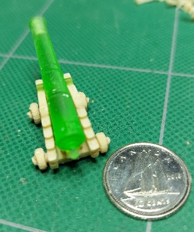
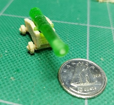
I must admit at first glance they do sort of look like the chewable candy! They were modelled and 3D printed for me by a member of our local club. I posted all about it earlier last year I believe. The carriage could use a little more cleaning up if I was using it... but it was a test piece. I added the quoin to the computer model and am 3D printing four at once at this moment. Should be done in about 2 hours at a material cost of 16 cents. That is $ Cdn 0.04 each Going for my eye needle on Tuesday late morning so I will be working on 3D printing during the week.
-
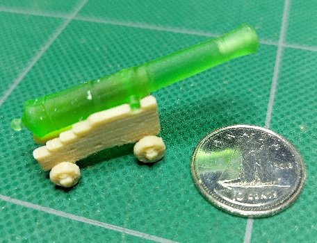
Here it is cleaned up a bit with the short 9 pound cannon mounted. I had not yet modelled the quoin into the assembly so the barrel is a bit high. Happily the trunnions mate perfectly to the carriage. The wood filament PLA material sand quite nicely with regular sand paper.
-
Yes, it was quite the down pour. I had a little water in the basement in the furnace room due to a patio block sloping the wrong way and possibly a crack in the wall. I adjusted the patio block but could not find a crack. Guess we will find out tomorrow as they are calling for more rain. Below is the carriage as removed from the printer. The supports have not been removed yet... it needs some clean up. It measures 19.9 x 17.3 x .43 mm or .78 x .68 x .43 inches. I will clean it up in a bit and set a 9 pound cannon barrel on it.
-
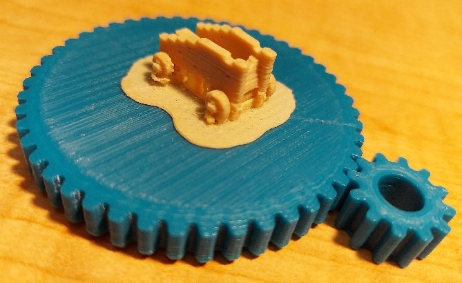
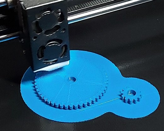
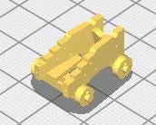
Did not get to the shop yesterday or today. Had a crew over removing my eaves troughs and fascia. Expected them back today to install the new, deeper, with leaf guard system... of course they didn't show up. Worked on and printed a set of gears for my future rope walk. They turned out quite good. Then I worked on my 3D 9 pound gun carriage. It is presently printing in wood filament. It is quite small so I am not sure how it will turn out. Could get the filament to feed through the 0.2mm nozzle so changed it to a 0.3mm nozzle and it seems to be working so far. Nothing much yet to see on the printer so here is the slicer program image.
-
AL L'Hermione - How to rig blocks at mast crossings
AON replied to Spike1947's topic in Masting, rigging and sails
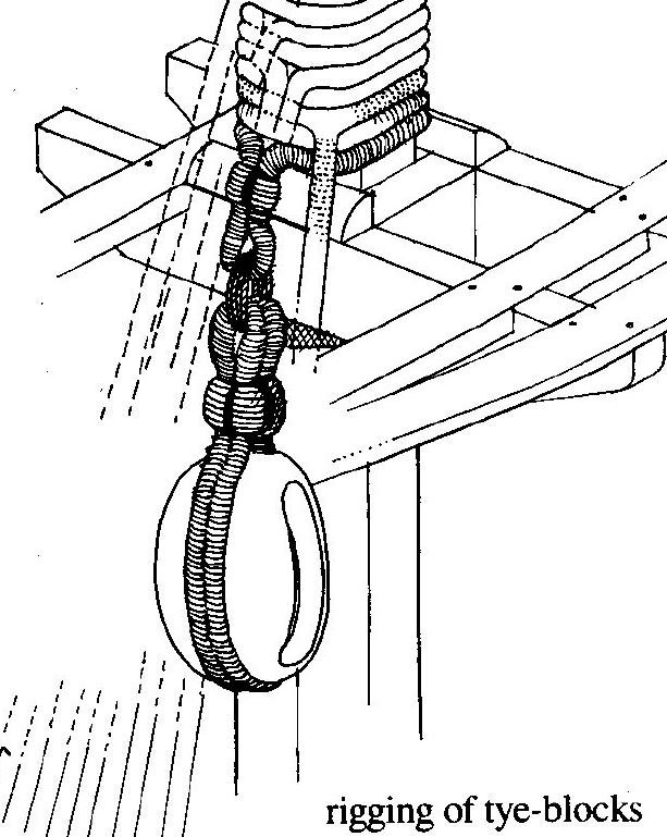
A good book for rigging French ships is The Seventy-Four Gun Ship, Volume 3, by Jean Boudriot. Page 130 shows a single line wrapped about the mast with the two ends dangling to one side of the mast. A thimble is eye spliced into each end. The bight around the mast is seized tight up to the mast. The block has a strop and thimble, and it is lashed to the dangling thimble mentioned earlier. Page 133 has the tye block strop eye lashed to an eye of a strop looped around the mast. You should get this book, translated to English version unless you are fluent en Français.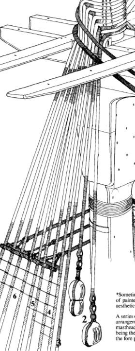
-
Jason It seems some were lashed as discussed above where as others were a single splice strop making an oversized loop of rope (line). The deadeye (or thimble which is the example I am looking at in The Anatomy of Nelsons Ships, page 235) is fitted with the "item" inside the strop, rope in the groove and wrapped around it, then seized tightly to it. Possibly this is what was done in your case.
-
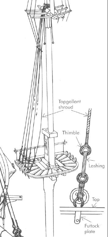
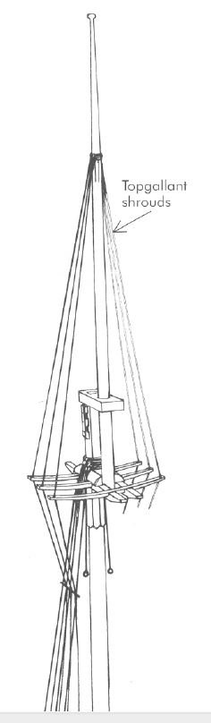
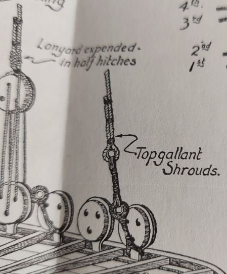
Reading The Anatomy of Nelsons Ships (C.Nepean Longridge) page 233 and looking at the image in Rigging Period Ship Models - Square Rigged (Lennarth Petersson) page 11: "The first pair is doubled in the usual manner, the third shroud goes over the mast head with an eye splice." "Each shroud reeves through a hole in the outer end of the top mast cross trees, where it is served. Inclined inwards, the shrouds pass between the topmast shrouds, and inside the topmast futtock stave." "The top gallant shrouds are lashed to the first, third and fifth futtock plates on the fore and main masts, to the first and third on the mizzen."
-
Here is another image. I will see If I can find the other end of the shroud.
-
Seems the foot or bottom of the column is pocketed into the deck (hidden or dashed lines below the top surface of the deck in the image). The head or top also is recessed into the beam from one side allowing it to slide out once the beam is lifted.
-
Thank you Siggi, I have been wondering how they would swing a column up if it were hinged without the foot of the column being rounded to allow it to pivot, or even pull a column out. Hinged or not... of course they jacked the overhead beam up a smidgen to create the necessary clearance! DUH.

